
High-Energy Beam Welding Processes in Manufacturing · High-Energy Beam Welding Processes in...
20
High-Energy Beam Welding Processes in Manufacturing Chen Hui-Chi*, Bi Guijun and Sun Chen-Nan Singapore Institute of Manufacturing Technology (SIMTech), Agency for Science, Technology and Research (A*STAR), Singapore, Singapore Abstract Today, high-energy beams, such as laser and electron beams, have been increasingly adopted in the industry for welding, cladding, and additive manufacturing. Due to the high-energy density and small beam size, welding and additive manufacturing using high-energy beams show the charac- teristics of deep penetration, low heat input, small heat-affected zone, low thermal distortion, good dimensional accuracy and integrity, as well as ease of automation. Compared with other types of heat sources (i.e., arc and plasma), high-energy beams are more suitable for the applications requiring a precise control of heat energy for difficult-to-process materials. Other than the abovementioned characteristics, high-energy beam welding process belongs to a contactless process which provides more flexibility in new design and manufacturing. With these superior characteristics, high-energy beam welding process has been used in a wide range of industrial sectors (i.e., aerospace, automo- tive, oil and gas, shipyard, medical devices, etc.) and is expected to keep playing an important role in welding industry in the future. Introduction The purpose of this chapter is to introduce the fundamentals of high-energy beam (laser and electron beams) welding and additive manufacturing, as well as the industrial applications. In the first two sections of this chapter, fundamentals of laser welding and electron beam welding are introduced, respectively. The associated parameters of the welding processes, such as welding system, processing parameters, and material properties of welding samples, are discussed. Furthermore, general welding defects which can cause quality deterioration are mentioned as well. Following the welding sections, fundamental and industrial applications of laser cladding technology are presented in the third section of this chapter. In this section, laser cladding with wire and powder feeding are introduced. General process variables and the ranges of parameters applied in laser cladding are highlighted. Approaches of calculating and controlling the dilution rate in laser cladding are also mentioned in this section. The last part of this chapter focuses on the process of selective laser sintering. The fundamental of selective laser sintering is introduced. Sintering mechanisms are discussed in detail. Some industrial examples of selective laser sintering are provided in this section as well. *Email: [email protected] Handbook of Manufacturing Engineering and Technology DOI 10.1007/978-1-4471-4976-7_54-1 # Springer-Verlag London 2014 Page 1 of 20
Transcript of High-Energy Beam Welding Processes in Manufacturing · High-Energy Beam Welding Processes in...

High-Energy Beam Welding Processes in Manufacturing
Chen Hui-Chi*, Bi Guijun and Sun Chen-NanSingapore Institute of Manufacturing Technology (SIMTech), Agency for Science, Technology and Research(A*STAR), Singapore, Singapore
Abstract
Today, high-energy beams, such as laser and electron beams, have been increasingly adopted in theindustry for welding, cladding, and additive manufacturing. Due to the high-energy density andsmall beam size, welding and additive manufacturing using high-energy beams show the charac-teristics of deep penetration, low heat input, small heat-affected zone, low thermal distortion, gooddimensional accuracy and integrity, as well as ease of automation. Compared with other types of heatsources (i.e., arc and plasma), high-energy beams are more suitable for the applications requiringa precise control of heat energy for difficult-to-process materials. Other than the abovementionedcharacteristics, high-energy beam welding process belongs to a contactless process which providesmore flexibility in new design and manufacturing. With these superior characteristics, high-energybeam welding process has been used in a wide range of industrial sectors (i.e., aerospace, automo-tive, oil and gas, shipyard, medical devices, etc.) and is expected to keep playing an important role inwelding industry in the future.
Introduction
The purpose of this chapter is to introduce the fundamentals of high-energy beam (laser and electronbeams) welding and additive manufacturing, as well as the industrial applications. In the first twosections of this chapter, fundamentals of laser welding and electron beam welding are introduced,respectively. The associated parameters of the welding processes, such as welding system,processing parameters, and material properties of welding samples, are discussed. Furthermore,general welding defects which can cause quality deterioration are mentioned as well. Following thewelding sections, fundamental and industrial applications of laser cladding technology are presentedin the third section of this chapter. In this section, laser cladding with wire and powder feeding areintroduced. General process variables and the ranges of parameters applied in laser cladding arehighlighted. Approaches of calculating and controlling the dilution rate in laser cladding are alsomentioned in this section. The last part of this chapter focuses on the process of selective lasersintering. The fundamental of selective laser sintering is introduced. Sintering mechanisms arediscussed in detail. Some industrial examples of selective laser sintering are provided in this sectionas well.
*Email: [email protected]
Handbook of Manufacturing Engineering and TechnologyDOI 10.1007/978-1-4471-4976-7_54-1# Springer-Verlag London 2014
Page 1 of 20
Laser Welding
Laser welding is increasingly used in a wide range of industrial applications due to its outstandingcharacteristics such as high-energy density, high precision, high speed, high flexibility for weldingthree-dimensional components, as well as producing a weld with a high aspect ratio of weld depth towidth. In this section, general information in laser welding will be provided including fundamentalsof physical mechanisms occurring in laser welding and key parameters generally used and itsadvantages for industry.
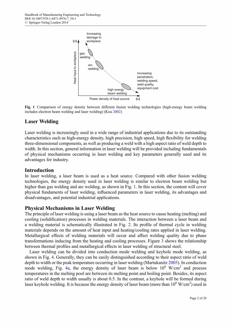
IntroductionIn laser welding, a laser beam is used as a heat source. Compared with other fusion weldingtechnologies, the energy density used in laser welding is similar to electron beam welding buthigher than gas welding and arc welding, as shown in Fig. 1. In this section, the content will coverphysical fundaments of laser welding, influenced parameters in laser welding, its advantages anddisadvantages, and potential industrial applications.
Physical Mechanisms in Laser WeldingThe principle of laser welding is using a laser beam as the heat source to cause heating (melting) andcooling (solidification) processes in welding materials. The interaction between a laser beam anda welding material is schematically illustrated in Fig. 2. Its profile of thermal cycle in weldingmaterials depends on the amount of heat input and heating/cooling rates applied in laser welding.Metallurgical effects of welding materials will occur and affect welding quality due to phasetransformations inducing from the heating and cooling processes. Figure 3 shows the relationshipbetween thermal profiles and metallurgical effects in laser welding of structural steel.
Laser welding can be divided into conduction mode welding and keyhole mode welding, asshown in Fig. 4. Generally, they can be easily distinguished according to their aspect ratio of welddepth to width or the peak temperature occurring in laser welding (Martukanitz 2005). In conductionmode welding, Fig. 4a, the energy density of laser beam is below 106 W/cm2 and processtemperatures in the melting pool are between its melting point and boiling point. Besides, its aspectratio of weld depth to width usually is about 0.5. In the contrast, a keyhole will be formed duringlaser keyhole welding. It is because the energy density of laser beam (more than 106 W/cm2) used in
Increasingdamage toworkpiece
Increasingpenetration,welding speed,weld quality,equipment costhigh energy
beam welding
arcwelding
gaswelding
Power density of heat source
Hea
t inp
ut to
wor
kpie
ce
(+)
(+)
Fig. 1 Comparison of energy density between different fusion welding technologies (high-energy beam weldingincludes electron beam welding and laser welding) (Kou 2002)
Handbook of Manufacturing Engineering and TechnologyDOI 10.1007/978-1-4471-4976-7_54-1# Springer-Verlag London 2014
Page 2 of 20

Weld pool
Heat-affected zone
Fusion zone
Base metal
Heat source
Fig. 2 Illustration of the interaction between laser beam and welding material in laser welding (David and Debroy 1992)
Temperature
Homogenous melt 1536°C A1 B peritectium
melt
1147°C
Keutectoid
g + Fe3C
Eg
400°C600°C
1000°C1200°C1600°C
G
BM
recrystallise
Heat affected zone 0.78 %C 2.06
Partial austenitic
Fine-grained region
Partial melt
S
O
Fig. 3 Relationship between thermal profiles and phase transformations in laser welding of structure steel (Bruggemannet al. 2000)
Fig. 4 Type of laser welding: (a) conduction mode welding and (b) keyhole mode welding (BOC 2009)
Handbook of Manufacturing Engineering and TechnologyDOI 10.1007/978-1-4471-4976-7_54-1# Springer-Verlag London 2014
Page 3 of 20

keyhole mode welding is higher enough for vaporizing welding materials and therefore formsa keyhole and plasma, as shown in Fig. 4b. A higher aspect ratio of weld depth to width (higherthan 0.5) will be obtained in keyhole mode welding because multi-reflections of laser beam causedon the keyhole walls can enhance energy absorption. The peak temperature occurring in this modeusually is higher than the boiling point of welding material.
Regarding thermal profiles in welding materials, three different metallurgical zones generally aredefined and named as fusion zone (FZ), heat-affected zone (HAZ), and base material (BM), asindicated in Fig. 2. During laser welding, the peak temperature of welding material happens in FZand usually is higher than its melting point or even boiling point. A keyhole will be formed andwelding material will be vaporized if the peak temperature of welding material is higher than itsboiling point. Normally, temperatures in HAZ are between melting point of welding materials androom temperature which can induce phase transformations resulting in changes of its microstructureand mechanical properties.
Influenced ParametersParameters in laser welding can be classified in laser system parameters, welding material param-eters, and processing parameters, as shown in Fig. 5. Each parameter plays a role in determiningwelding performance and welding quality. Among, laser system parameters are not able to bechanged once a laser system has been chosen before laser welding. Based on material parametersused in developing laser welding process, processing parameters will be varied in a range tooptimize the process. In the following sections, the role of each parameter in laser welding will bebriefly introduced.
Laser System ParametersMaximum output of laser power is an index to predict a laser system’s capability used in laserprocesses. A laser system with a higher maximum output of laser power provides a wide workingwindow in terms of material type, thickness of material to weld, as well as a higher welding speedthat can be used in laser welding. Except maximum laser power output, laser beam quality and itswavelength are other important technical parameters which determine where a laser system can beapplied and what welding quality can be achieved. Generally speaking, a better laser beam quality
Fig. 5 Influenced parameters in laser welding
Handbook of Manufacturing Engineering and TechnologyDOI 10.1007/978-1-4471-4976-7_54-1# Springer-Verlag London 2014
Page 4 of 20

provides a smaller laser beam focus diameter resulting in a higher energy density and a keyholemode welding. In the aspect of laser beam wavelength, it also affects welding performance.The relationship between laser beam wavelength, laser energy reflectivity, and material type isshown in Fig. 6.
Laser power delivery method can be classified into continuous wave (CW) and pulsed wave(PW)modes. In laser CWmode welding, laser power used is kept at the same value. Adversely, laserpower can be varied with time during laser PW welding depending on the settings of type of pulsedwave, average laser power, peak power, pulse duration and frequency, etc. Laser PW weldingusually used in applications required a precise controlling on heat input and heating/cooling rates.However, laser CW welding is more widely used in industry. Compared with PW welding, theadvantages of laser CW welding are its low investing cost, capability of performing a higher-speedwelding, and better weld appearance.
Welding Material PropertiesIn general, properties of welding material can be considered as factors to determine the settings ofprocessing parameters. This part will be discussed in the next section. Before laser welding is carriedout, type of welding material and its thickness are the first parameters to be checked before settingother processing parameters. For example, thickness of welding material will affect the setting oflaser power, welding speed, or even the number of welding pass. Thicker materials may needa multi-pass welding or keyhole mode welding to achieve a penetration weld compared withwelding of a thinner material, such as a foil, by using a conduction mode welding.
Regarding the type of welding material, its optical, physical, and mechanical properties have to beconsidered. Optical properties of welding material, such as laser light reflectivity, will influence theprocess stability and welding efficiency. Physical and chemical properties of welding materialusually play roles in determining laser welding performance and welding quality. With thesereasons, thermal conductivity, density, diffusivity, and absorption of a laser beam are usuallyconsidered since they can affect heat distributions in welding materials. Besides, a material witha high thermal conductivity or a low absorption will decrease laser welding efficiency. At the same
Yb:YAGλ=258 μm
Yb:YAGλ=343 μm
Yb:YAGλ=515 μm
Diodeλ~900 μm CO2
λ=10,6 μmYb:YAG
λ=1,030 μm
100
80
60
40
20Abs
orpt
ion
in %
0Al
UV
0,1 0,3 1
Wavelength in μm
3
IR
Fe
Glass
Ag
10
Fig. 6 Relationship between laser beam wavelength, laser energy absorption, and material type (Stollhof 2009)
Handbook of Manufacturing Engineering and TechnologyDOI 10.1007/978-1-4471-4976-7_54-1# Springer-Verlag London 2014
Page 5 of 20

time, welding efficiency can be affected by material absorption of the laser beam. Absorptiondepends on material type and laser beam wavelength, as shown in Fig. 6. For example, Al and Cualloys have been recognized as lower absorptive materials compared with other metallic materialswhen laser beam wavelength is beyond the infrared range.
Processing ParametersIn laser welding, processing parameters generally can be laser power, welding speed, focal pointposition of the laser beam, type of shielding gas and its setup, etc. Laser power and welding speed aretwo main processing parameters which can affect the amount of heat input delivered to weldingmaterials. Welding performances, such as weld geometry, weld defects, and macro/micro segrega-tions in welds, can be different according to the total amount of heat energy that has been absorbedand transferred in welding materials. The amount of heat input applied in laser welding is changedby increasing laser power or decreasing welding speed when other parameters are kept. If thethickness of welding material is given, laser power will be increased with an increase of weldingspeed.
Instead of varying laser power or welding speed, locating the focal point of laser beam at differentpositions is another way to change the amount of heat input applied to welding materials. It isbecause energy density and beam size of the laser beam irradiated on the top surface of weldingmaterials will be different when the focal point of the laser beam is located at different positions (i.e.,above, on, and below the top surface of welding materials), as illustrated in Fig. 7.
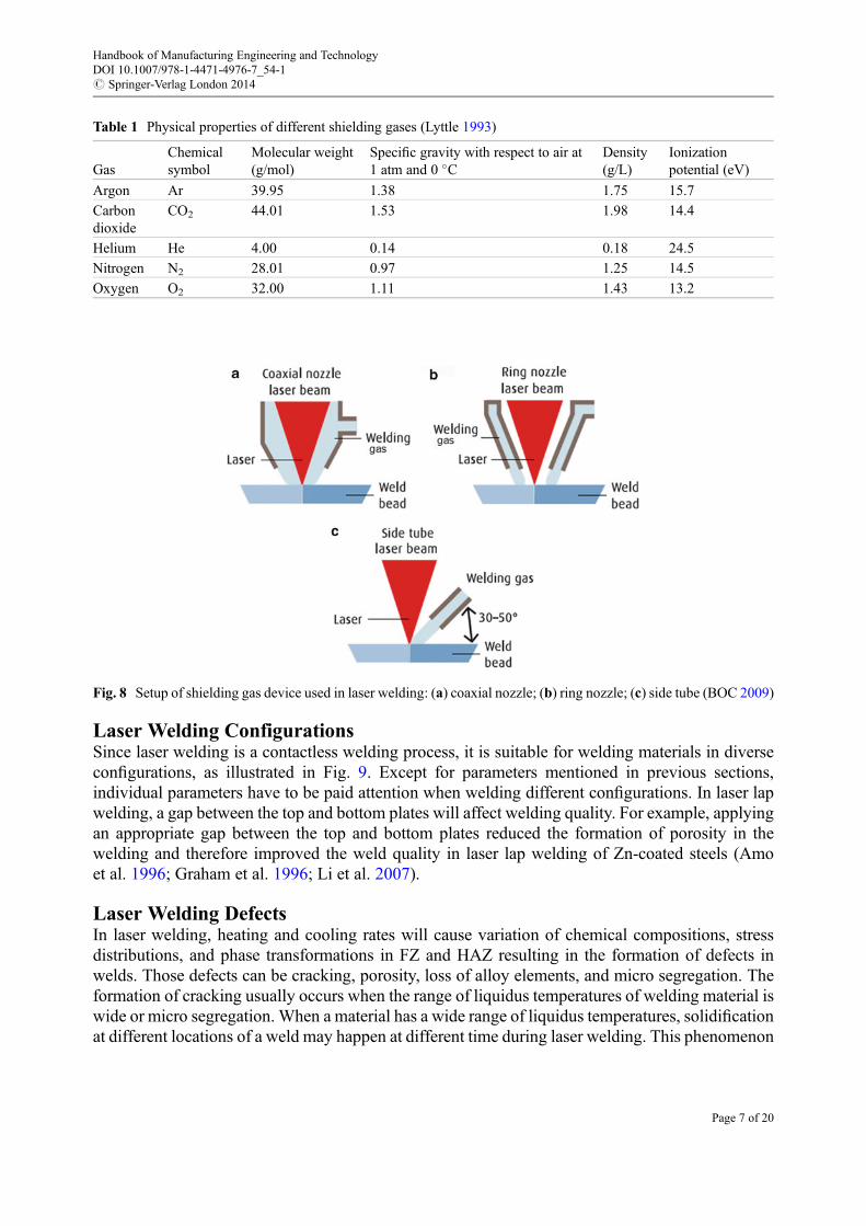
The function of shielding gas used in laser welding is to protect melting pools from oxidation,suppress the plasma formed above the melting pool as well as avoid optical damage of lens fromspatter during welding. Table 1 summarizes physical properties of different shielding gases com-monly used in laser welding. According to the materials to be welded, choice of shielding gas, flowrate of shielding gas, diameter of nozzle, and setup of shielding gas device (Fig. 8) have to beoptimized for achieving good welds. Currently, helium, argon, and nitrogen gases are frequentlyused in laser welding.
Fig. 7 Illustration of different focal point positions in laser welding: (a) laser beam focuses above a welding material(defocused); (b) laser beam focuses on a welding material (focused); (c) laser beam focuses below a welding material(defocused)
Handbook of Manufacturing Engineering and TechnologyDOI 10.1007/978-1-4471-4976-7_54-1# Springer-Verlag London 2014
Page 6 of 20
Laser Welding ConfigurationsSince laser welding is a contactless welding process, it is suitable for welding materials in diverseconfigurations, as illustrated in Fig. 9. Except for parameters mentioned in previous sections,individual parameters have to be paid attention when welding different configurations. In laser lapwelding, a gap between the top and bottom plates will affect welding quality. For example, applyingan appropriate gap between the top and bottom plates reduced the formation of porosity in thewelding and therefore improved the weld quality in laser lap welding of Zn-coated steels (Amoet al. 1996; Graham et al. 1996; Li et al. 2007).
Laser Welding DefectsIn laser welding, heating and cooling rates will cause variation of chemical compositions, stressdistributions, and phase transformations in FZ and HAZ resulting in the formation of defects inwelds. Those defects can be cracking, porosity, loss of alloy elements, and micro segregation. Theformation of cracking usually occurs when the range of liquidus temperatures of welding material iswide or micro segregation. When a material has a wide range of liquidus temperatures, solidificationat different locations of a weld may happen at different time during laser welding. This phenomenon
Fig. 8 Setup of shielding gas device used in laser welding: (a) coaxial nozzle; (b) ring nozzle; (c) side tube (BOC 2009)
Table 1 Physical properties of different shielding gases (Lyttle 1993)
GasChemicalsymbol
Molecular weight(g/mol)
Specific gravity with respect to air at1 atm and 0 �C
Density(g/L)
Ionizationpotential (eV)
Argon Ar 39.95 1.38 1.75 15.7
Carbondioxide
CO2 44.01 1.53 1.98 14.4
Helium He 4.00 0.14 0.18 24.5
Nitrogen N2 28.01 0.97 1.25 14.5
Oxygen O2 32.00 1.11 1.43 13.2
Handbook of Manufacturing Engineering and TechnologyDOI 10.1007/978-1-4471-4976-7_54-1# Springer-Verlag London 2014
Page 7 of 20

will induce uneven stress distributions across a weld and fractures resulting to initiations of failureunder fatigue environments.
Weld porosity is another common issue in laser welding, especially for welding of light metals,such as aluminum alloys and titanium alloys. Mechanisms to form weld porosity can be due to quicksolidification rate in FZ and a rapid closure of the keyhole in laser welding, as illustrated in Fig. 10a,b, respectively. In Fig. 10a, the shielding gas used or air are unable to leave the keyhole before FZ issolidified. It is due to the nature of quick heating and cooling rates in laser welding. This type ofporosity usually is founded in the middle of welds. Another reason which can cause porosity is dueto an unstable melting pool during laser welding. The front wall of a keyhole easily falls, particularlyfor those materials that have low surface tension and viscosity and therefore form a void in the tip ofweld, as shown in Fig. 10b. Normally, weld porosity will induce stress concentrations leading toearly failures of welds.
In laser keyhole mode welding, molten materials may be brought out from the keyhole byvaporized forces, as captured in Fig. 11. General influences of spatters are degradations of corrosionresistance and unsuccessful assembly with other components after laser welding. An example ofspatter formed on the top surface of a weld is shown in Fig. 12. Typical remedies for minimizing theformation of spatter are optimizing processing parameters (i.e., laser power, welding speed, type ofshielding gas) and using filler materials.
Fig. 9 Laser welding type: (a) butt welding; (b) fillet welding; (c) lap welding; (d) spot welding; (e) flange welding; (f)edge welding; (g) T-joint welding; (h) flare welding; (i) corner welding; (j) kissing welding (Steen andMazumder 2010)
Handbook of Manufacturing Engineering and TechnologyDOI 10.1007/978-1-4471-4976-7_54-1# Springer-Verlag London 2014
Page 8 of 20

Electron Beam Welding
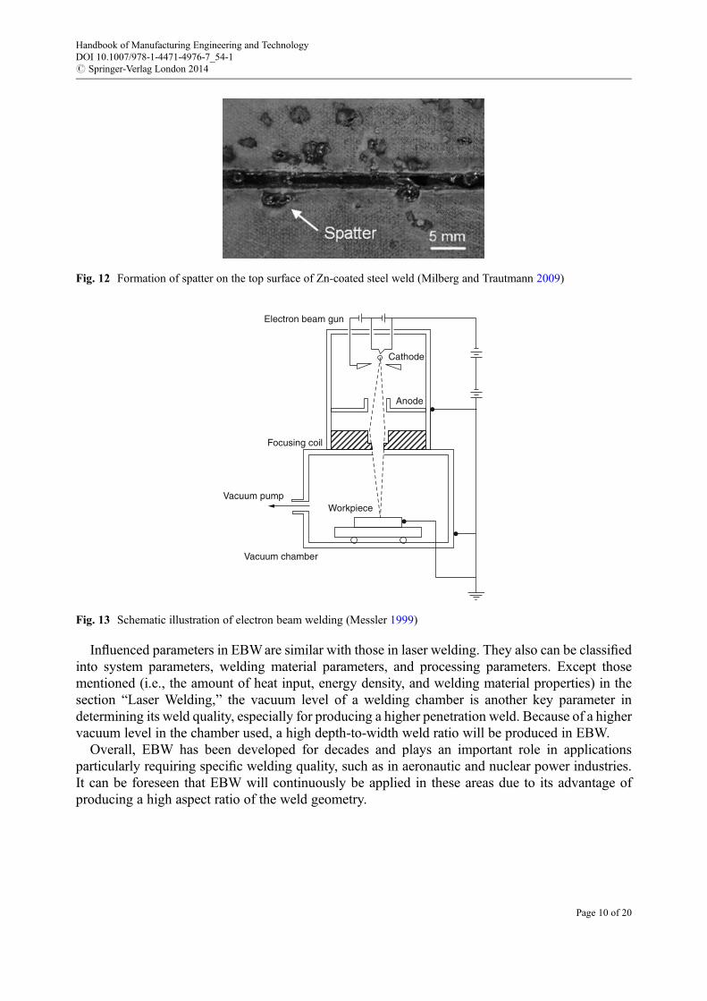
Similar to laser welding, electron beam welding (EBW) has a high-energy density compared withother fusion welding technologies, as shown in Fig. 1. A general setup of EBW is illustrated inFig. 13. In EBW, the kinetic energy will be transferred to heat energy when electrons strike thewelding materials. With this mechanism, a high-vacuum environment (10�3–10�5 atm) is normallyrequired in EBW. It is because any air or gas can affect the electron flow during welding. A highervacuum environment applied in welding, a deeper and narrower weld will be produced. Its weldgeometry is similar with a weld produced from laser keyhole mode welding. Compared with otherfusion welding technologies, not only a wide range of material thicknesses is able to be welded butalso no shielding gas and filler material are required in EBW. Today, EBW has been used in thesectors of civil, aerospace, nuclear, and electric power plants.
Laser beama
b
Molten pool
Molten pool
Keyhole Porosity
PorosityKeyhole
Laser beam
Fig. 10 Mechanisms to form weld porosity: (a) quick solidification rate; (b) rapid closure of the keyhole (Kawahitoet al. 2006)
Fig. 11 Image of a melting behavior captured during laser welding (Katayama and Kawahito 2009)
Handbook of Manufacturing Engineering and TechnologyDOI 10.1007/978-1-4471-4976-7_54-1# Springer-Verlag London 2014
Page 9 of 20
Influenced parameters in EBWare similar with those in laser welding. They also can be classifiedinto system parameters, welding material parameters, and processing parameters. Except thosementioned (i.e., the amount of heat input, energy density, and welding material properties) in thesection “Laser Welding,” the vacuum level of a welding chamber is another key parameter indetermining its weld quality, especially for producing a higher penetration weld. Because of a highervacuum level in the chamber used, a high depth-to-width weld ratio will be produced in EBW.
Overall, EBW has been developed for decades and plays an important role in applicationsparticularly requiring specific welding quality, such as in aeronautic and nuclear power industries.It can be foreseen that EBW will continuously be applied in these areas due to its advantage ofproducing a high aspect ratio of the weld geometry.
Electron beam gun
Cathode
Anode
Focusing coil
Vacuum pumpWorkpiece
Vacuum chamber
Fig. 13 Schematic illustration of electron beam welding (Messler 1999)
Fig. 12 Formation of spatter on the top surface of Zn-coated steel weld (Milberg and Trautmann 2009)
Handbook of Manufacturing Engineering and TechnologyDOI 10.1007/978-1-4471-4976-7_54-1# Springer-Verlag London 2014
Page 10 of 20

Laser Cladding
IntroductionLaser cladding is a metal coating process in which laser is utilized as a heat source to generate a meltpool on the substrate surface and at the same time deposit the additive material in the form of powderor wire on to the substrate. As both a thin layer of the substrate and the additive material are fullymelted, metallurgical bonding can be formed with very high bonding strength. Laser cladding can bewidely used for improving corrosion, erosion, and wear resistance as well as for repair andmodification of damaged/worn parts. Electrical arc (MIG and TIG), plasma arc, and laser are mostlyused heat sources for cladding. Laser cladding shows several advantages over other traditionalsurface cladding technologies such as PTA and TIG.
Process Principle of Laser CladdingLaser cladding can be classified as a two-stage process with pre-placed additive material anda one-stage process with in situ fed material in the form of powder or wire. In the one-stage process,the additive materials can be fed into the melt pool either laterally or coaxially to the laser beam.Cladding with coaxial powder feeding prevails over other methods, because this feeding methodguarantees a multidirectional and more flexible process. The powders with a typical diameter of20–150 mm are fed through a coaxial powder nozzle by the carrier gas (e.g., Ar, He) into the meltpool. The gas also has the function of a shielding gas to prevent the clad layer from oxidation. Thelaser beam melts a thin layer of the work piece (in the100 m range) and the fed powder simulta-neously. Thus, the melted powder and the base material are metallurgically bonded with up to 100%density. Figure 14 shows schematically the one-stage laser cladding process with coaxial powderfeeding. Figure 15 shows schematically the one-stage laser cladding with lateral wire feeding (Moket al. 2008). During laser cladding process, the heat input is limited to the local area, which resultsfrom the good focusability of the laser beam. As a result, a small heat-affected zone (HAZ) and lowdilution in the base material can be achieved. Typical depth of the HAZ ranges from a few hundredmicrons to one millimeter.
Dilution is defined as the amount of intermixing of the clad material with base material. Lowdilution means there is very little of the base material mixed with the clad, which means that theproperties of the clad layer is very close to the original additive material. This ensures that the fullfunctions of the clad can be achieved in one single layer. Figure 16 shows schematically theevaluation of the cross section of the clad track (Bi et al. 2006). Dimensions of the clad layer,
Laser beam Focusing lens
Powder andcarrier gas inlet
Powder nozzles
Powder jetMelt pool
Substrate
Clad layer
Powder andcarrier gas inlet
Fig. 14 One-stage laser cladding with coaxial powder feeding
Handbook of Manufacturing Engineering and TechnologyDOI 10.1007/978-1-4471-4976-7_54-1# Springer-Verlag London 2014
Page 11 of 20

HAZ, and dilution zone can be measured in the cross section of the clad. The dilution � can beroughly calculated with Eq. 1:
� ¼ HD
HC þ HD(1)
Normally the dilution of laser cladding can be controlled in the range of 5–10 %. Figure 17 showsexamples of laser clad with low and high dilution.
Process ParametersThere are several parameters which govern the laser cladding process. A reasonable deposition ratewith sound layer quality can be achieved by an optimized set of process parameters. For lasercladding with powder, laser power PL, scanning speed vv, and powder feeding rate mp are the mostimportant process parameters, which determine the quality and geometry of the clad. As for thecladding with wire, the main process parameters are laser power PL, scanning speed vv, and powderfeeding rate mp/wire feeding rate mw. Typical ranges of the process parameters are shown in Table 2.
Fig. 16 Schematic diagram of the cross section of a clad
Laser head
Wire materialClad layer
Sub strate
Wire feeding direction
Copper nozzle
Wire feeder
Fig. 15 One-stage laser cladding with lateral wire feeding
Handbook of Manufacturing Engineering and TechnologyDOI 10.1007/978-1-4471-4976-7_54-1# Springer-Verlag London 2014
Page 12 of 20

MaterialsAwide range of materials can be used for direct laser deposition process. Besides the normal carbonsteels, many other kinds of metals, including tool steels, powder metallurgy steels, and Ni-basedsuperalloys, Ti-based superalloys, Cu-based alloys, and Al-based alloys, can be used as basematerial. For the additional materials, many kinds of alloys can be used. The commercially availablepowders and wires used for the thermal spraying processes can be utilized in laser cladding. Co-, Ni-,Fe-, Al-, Cu-, Ti-based alloys are commonly applied. The powders are more commercially availableand more flexible to fit for the deposition process than wire. However, wire deposition can achievenearly 100 % material usage, which is the main advantage over laser cladding using powder. Lasercladding can be also used to generate functionally graded layers.
ApplicationsThe applications of laser cladding have been widely explored. It has been successfully introducedinto industry for deposition of wear and/or corrosion resistant coatings, repair of turbine compo-nents, moulds and dies, as well as rapid tooling (Leunda et al. 2011; Schubert et al. 1999; Meiet al. 2003; Thivillon et al. 2009; Peyre et al. 2008). This process is extremely suitable for the high-mix-low-volume production with high value added. The applications can be widely found in nearlyall the industry sectors, including aerospace, marine and offshore, oil and gas, medical, precisionengineering and military, etc.
Example 1. In the paper industry, cutting rollers are applied for cutting and punching paper. Thecutting blade must have the properties of enough hardness, wear resistance, and significant
Table 2 Comparison of the main properties of different high-power lasers
Process parameter Typical range
Laser power PL 200–3,000 W (Nd: YAG/diode/fiber laser)
500–10,000 W (CO2 laser)
Beam size 0.5–6 mm (in diameter)
Power intensity I 5 * 103–105 W/cm2
Scanning speed vv 50–2,000 mm/min
Powder feeding rate mp/wire feeding rate mw 1–30 g/min
Powder carrier gas (shielding gas) VSG 2–15 L/min Ar
Fig. 17 Photos showing the dilution level of laser clad. (a) Low dilution. (b) High dilution
Handbook of Manufacturing Engineering and TechnologyDOI 10.1007/978-1-4471-4976-7_54-1# Springer-Verlag London 2014
Page 13 of 20

toughness. Normally, it is machined by stock removal method using cold work tool steelX165CrMoV12. To reduce the costs and manufacturing time, the cutting blade will be depositedwith hot work tool steel X38CrMoV51 onto normal carbon steel C 45 and machined to the endgeometry. The deposited cutting blade and the cross section are shown in Fig. 18a, b, respectively.The optical examination in cross section proves that the deposited layer is free of porosity and crack.The hardness in the layer amounts to 700 HV0.3. Figure 18c shows the cutting roller aftermachining.
Example 2. Laser cladding is suitable for applications in which only minimum distortion can betolerated, as well as for materials that are difficult to clad using conventional methods, for example,high-temperature-resistant nickel-based alloys in gas turbines. Figure 19a shows the process ofrepairing the edge knife of an aeroengine blade made of nickel-based super alloy IN100. Therepaired blade in Fig. 19b shows a good dimensional accuracy.
Selective Laser Sintering
IntroductionSelective laser sintering (SLS) is a laser-based 3D additive manufacturing technique that buildsobjects layer by layer from powders using computer-aided design (CAD) technology. SLS techniqueis to some extent similar to other laser fabrication processes such as laser engineered net shaping(LENS) (Griffith et al. 2000; Keicher et al. 1997), direct metal deposition (DMD) (Dindaet al. 2009), laser metal deposition(LMD) (Gasser et al. 2010), etc. All of these techniques
Fig. 18 Cladding of the cutting blade on a cutting roller. (a) Cutting roller after deposition. (b) Cross section. (c) Cuttingroller after machinin
Handbook of Manufacturing Engineering and TechnologyDOI 10.1007/978-1-4471-4976-7_54-1# Springer-Verlag London 2014
Page 14 of 20

incorporate features from stereolithography and laser surface engineering, using a CAD model tocontrol sequentially thin-layered forming process. But unlike LENS, DMD, and LMD, wherepowders are delivered in a gas stream into the focus of a high-power laser beam to createa molten pool, the main difference in the SLS technique is that powders are spread from the feedbed across the part bed using a roller. After solidification of the melt, a thin solid layer is formed andfused to the previous sintered layer. By repeating the process, a nearly full dense structure can bemade. Schematic of SLS technique is shown in Fig. 20.
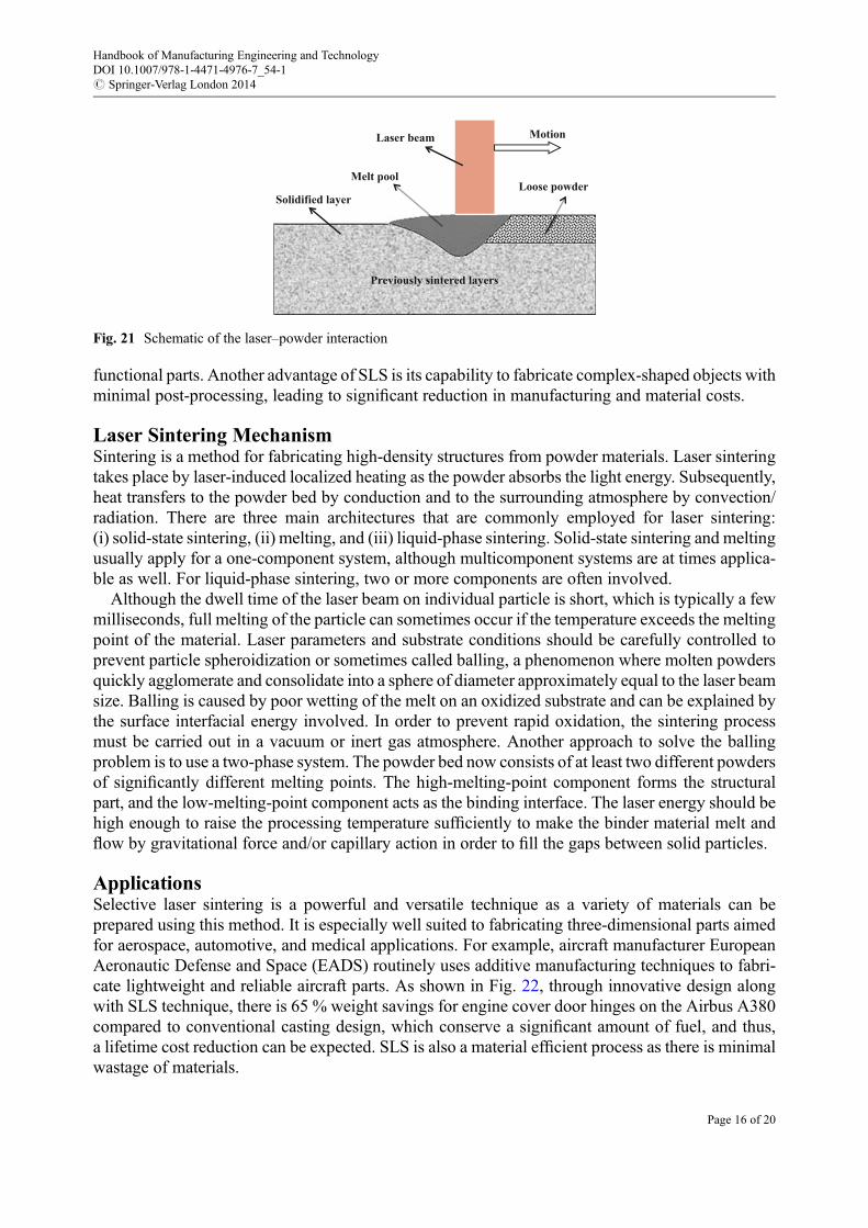
When the laser beam strikes the powder surface, as shown in Fig. 21, the laser–powder interactioncan be described by the following steps: (i) absorption of photons leading to an increase intemperature, (ii) mass transfer or diffusion prompts interparticle necking and grain growth, andfinally (iii) densification of the sintered objects.
As additional light energy is absorbed by the sintered powder and the temperature rises beyondthe melting point, powder material then undergoes partial or full melting. Surrounding particles aredragged into the melt pool to decrease surface tension, i.e., reduction of surface energy. As thescanning laser beam proceeds to the neighboring powder bed, the melt pool eventually cools downand starts to solidify, forming grains on the remelted surface of the previous layer (Das 2003).Densification is attained as pores are filled by molten material. Studies have demonstrated that SLScan process high-temperature, high-performance materials such as Ni- or Ti-based alloys into
Repair in process
a b
Repaired aero-engine blade
10 mm5 mm
Fig. 19 Repair of aeroengine blade. (a) Repair in process. (b) Repaired aeroengine blade
Scanner Laser
RollerPowder bed
Sintered part
Piston moves down
Piston moves up
Inert gas atmosphere
Fig. 20 Schematic of the selective laser sintering setup
Handbook of Manufacturing Engineering and TechnologyDOI 10.1007/978-1-4471-4976-7_54-1# Springer-Verlag London 2014
Page 15 of 20
functional parts. Another advantage of SLS is its capability to fabricate complex-shaped objects withminimal post-processing, leading to significant reduction in manufacturing and material costs.
Laser Sintering MechanismSintering is a method for fabricating high-density structures from powder materials. Laser sinteringtakes place by laser-induced localized heating as the powder absorbs the light energy. Subsequently,heat transfers to the powder bed by conduction and to the surrounding atmosphere by convection/radiation. There are three main architectures that are commonly employed for laser sintering:(i) solid-state sintering, (ii) melting, and (iii) liquid-phase sintering. Solid-state sintering and meltingusually apply for a one-component system, although multicomponent systems are at times applica-ble as well. For liquid-phase sintering, two or more components are often involved.
Although the dwell time of the laser beam on individual particle is short, which is typically a fewmilliseconds, full melting of the particle can sometimes occur if the temperature exceeds the meltingpoint of the material. Laser parameters and substrate conditions should be carefully controlled toprevent particle spheroidization or sometimes called balling, a phenomenon where molten powdersquickly agglomerate and consolidate into a sphere of diameter approximately equal to the laser beamsize. Balling is caused by poor wetting of the melt on an oxidized substrate and can be explained bythe surface interfacial energy involved. In order to prevent rapid oxidation, the sintering processmust be carried out in a vacuum or inert gas atmosphere. Another approach to solve the ballingproblem is to use a two-phase system. The powder bed now consists of at least two different powdersof significantly different melting points. The high-melting-point component forms the structuralpart, and the low-melting-point component acts as the binding interface. The laser energy should behigh enough to raise the processing temperature sufficiently to make the binder material melt andflow by gravitational force and/or capillary action in order to fill the gaps between solid particles.
ApplicationsSelective laser sintering is a powerful and versatile technique as a variety of materials can beprepared using this method. It is especially well suited to fabricating three-dimensional parts aimedfor aerospace, automotive, and medical applications. For example, aircraft manufacturer EuropeanAeronautic Defense and Space (EADS) routinely uses additive manufacturing techniques to fabri-cate lightweight and reliable aircraft parts. As shown in Fig. 22, through innovative design alongwith SLS technique, there is 65 % weight savings for engine cover door hinges on the Airbus A380compared to conventional casting design, which conserve a significant amount of fuel, and thus,a lifetime cost reduction can be expected. SLS is also a material efficient process as there is minimalwastage of materials.
Loose powderMelt pool
Previously sintered layers
MotionLaser beam
Solidified layer
Fig. 21 Schematic of the laser–powder interaction
Handbook of Manufacturing Engineering and TechnologyDOI 10.1007/978-1-4471-4976-7_54-1# Springer-Verlag London 2014
Page 16 of 20

Another application is for the automotive industry. As shown in Fig. 23, an air intake manifoldwas produced using a novel quasicrystal–polymer composite. Advantages of using this material inSLS process include low porosity and directly leak-tight without post-impregnation of resin.Compared to other composites such as polystyrene or polyamide filled with carbon fibers, glassparticles, or glass fiber used in SLS technology, it is found that friction is reduced and wear resistanceis improved.
Summary
High-energy beams have been widely used for various material joining purposes today. By usinga high-energy beam, a precision welding, cladding, and sintering can be carried out easily. In thischapter, fundamentals of laser and electron beam welding, laser cladding, and selective lasersintering are discussed systematically. Applications of each process are also included in eachsection. After going through this chapter, a basic understanding of each process and its potentialapplication should be obtained.
Fig. 22 Significant weight savings for engine cover door hinges on the Airbus A380 using SLS. The material used istitanium alloy Ti-6Al-4V (Fachot 2011)
Fig. 23 Air intake manifold created by selective laser sintering. The material used is AlCuFeB quasicrystal–polymercomposite (Kenzari et al. 2012)
Handbook of Manufacturing Engineering and TechnologyDOI 10.1007/978-1-4471-4976-7_54-1# Springer-Verlag London 2014
Page 17 of 20

References
Amo JM et al (1996) Laser welding of Al55-Zn coated steel sheet. J Mater Sci 31:6595–6607Bi G, Gasser A, Wissenbach K, Drenker A, Poprawe R (2006) Identification and qualification of
temperature signal for monitoring and control. Laser Cladd Opt Lasers Eng 44(12):1348–1359BOC (2009) LASERLINE technical laser weldingBruggemann G et al (2000) Comparison of experimental determined and numerical simulated
temperature fields for quality assurance at laser beam welding of steels and aluminium alloyings.NDT&E Int 33:453–463
Das S (2003) Physical aspects of process control in selective laser sintering of metals. Adv EngMater 5:701–711
David SA, Debroy T (1992) Current issues and problems in welding science. Science 257:497–502Dinda GP, Dasgupta AK, Mazumder J (2009) Laser aided direct metal deposition of Inconel
625 superalloy: microstructural evolution and thermal stability. Mate Sci Eng A 509:98–104Fachot M (2011) The 3D printing manufacturing revolution. http://www.iec.ch/etech/2011/
etech_0911/ind-3.htmGasser A, Backes G, Kelbassa I, Weisheit A, Wissenbach K (2010) Laser additive manufacturing.
Laser Technik J 7:58–63Graham MP et al (1996) Laser welding of Zn-coated sheet steels. Proc SPIE Int Soc Opt Eng
2703:170–183Griffith ML, EnszMT, Puskar JD, Robino CV, Brooks JA, Philliber JA, Smugeresky JE, Hofmeister
WH (2000) Understanding the Microstructure and properties of components fabricated by laserengineered net shaping (LENS). MRS Proc 625:9–20
Katayama S, Kawahito Y (2009) Elucidation of phenomena in high-power fiber laser welding anddevelopment of prevention procedures of welding defects. In: Presented at the proceedings of theSPIE – the international society for optical engineering, USA
Kawahito Yet al (2006) In-process monitoring and adaptive control for laser spot and seam weldingof pure titanium. J Laser Micro Nanoeng 1:269–274
Keicher DM, Smugeresky JE, Romero JA, Griffith ML, Harwell LD (1997) Using the laserengineered net shaping (LENS) process to produce complex components from a CAD solidmodel. Proc SPIE Int Soc Opt Eng 2993:91–97
Kenzari S, Bonina D, Dubois JM, Fournée V (2012) Quasicrystal–polymer composites for selectivelaser sintering technology. Mater Des 35:691–695
Kou S (2002) Welding metallurgy, 2nd edn. Wiley-Interscience, HobokenLeunda J, Soriano C, Sanz C, Navas V (2011) Laser cladding of vanadium-carbide tool steels for die
repair. Phys Proced 12:345–352Li X et al (2007) Novel technique for laser lap welding of zinc coated sheet steels. J Laser Appl
19:259–264Lyttle KA (1993) ASM handbook, vol 6. ASM International, Materials ParkMartukanitz RP (2005) A critical review of laser beam welding. Proc SPIE Int Soc Opt Eng
5706:11–24Mei H, Ouyang J, Hu D, Kovacevic R (2003) Rapid fabrication of functionally gradient material
parts by laser beam. In: Proceedings of 22nd international congress on applications of lasers &electro-optics (ICALEO), Jacksonville, pp 903–102
Messler RW (1999) Principles of welding: processes, physics, chemistry, and metallurgy. Wiley,New York
Handbook of Manufacturing Engineering and TechnologyDOI 10.1007/978-1-4471-4976-7_54-1# Springer-Verlag London 2014
Page 18 of 20

Milberg J, Trautmann A (2009) Defect-free joining of zinc-coated steels by bifocal hybrid laserwelding. Ger Acad Soc Prod Eng 3:9–15
Mok SH, Bi G, Folkes J, Pashby IR (2008) Deposition of Ti-6Al-4V using a high power diode laserand wire, Part 1: investigation on the process characteristics. Surf Coat Technol 202:3933–3939
Peyre P, Aubry P, Fabbro R (2008) Morphological and thermal modelling of direct metal deposition:application to aeronautical alloys. In: Proceedings of 27th international congress on applicationsof lasers & electro-optics (ICALEO), Temecula, pp 1–6
Schubert E, Seefeld T, Rinn A, Sepold G (1999) Laser beam cladding: a flexible tool for local surfacetreatment and repair. J Therm Spray Technol 8(4):590–596
Steen WM, Mazumder J (2010) Laser material processing. Springer, New YorkStollhof J (2009) Short course: laser beam sources – which laser for wich application. In: ICALEO
2009 – 28th international congress on applications of laser and electro-optics, OrlandoThivillon L, Bertrand P, Laget B, Smurov I (2009) Potential of direct metal deposition technology
for manufacturing thick functionally graded coatings and parts for reactors components. J NuclMater 385(2):236–241
Handbook of Manufacturing Engineering and TechnologyDOI 10.1007/978-1-4471-4976-7_54-1# Springer-Verlag London 2014
Page 19 of 20

Index Terms:
Absorption 5Additive manufacturing 14Difficult-to-process materials 14Dilution 11, 13Direct metal deposition 14Electron beam welding 9Fusion welding 2, 9High energy beam 1Laser cladding 11Laser conduction welding 2–3Laser keyhole welding 2Laser metal deposition 15Melting 2, 4Metallurgical bonding 11Selective laser sintering 1, 17Shielding gas 6–7Sintering mechanism 16Solidification 2Welding configuration 7Welding defects 7
Handbook of Manufacturing Engineering and TechnologyDOI 10.1007/978-1-4471-4976-7_54-1# Springer-Verlag London 2014
Page 20 of 20