Power 2.2kW / 3.0HP Discharge DIN DN40 PN10 Weight (Excl ...

Products That Meet “Top Runner” Standards
Gear MotorsHigh-Efficiency
IE2 IE3
Choose the model that is easiest for you to use.
MID SERIESIE3 GEAR MOTORS 0.75kW-2.2kW
NEW MODEL

IE3
IE2
IE1
92
90
88
86
84
82
80
78
76
740.75kW
85.586.5
89.5
87.5
83.084.0
81.582.5
78.0
1.5kW 2.2kW
● ●
IE3
IE2
IE1
2010 2011 2012 2013 2014 2015 2016 2017 2018
1
The trend toward high-efficiency regulatory
standards in Japan and other countries
In Japan, the Ministry of Economy, Trade and Industry (METI) enacted the Act on the Rational Use of Energy in November 2013 with the aim of improving motors. It established regulatory standards for a “top runner” class with a target enactment date of 2015*. Motor manufacturers have been obligated to meet these standards since their establishment in April 2015. At our company, we have transitioned our gear motor products to premium efficiency levels under the designation “IE3” in compliance with the new Japanese standards as well as high-efficiency standards in other countries.
●Top Runner Standard Motors
Japan
Europe
China
S. Korea
USA
June 2011 IE2 0.75kW~
April 2015 IE3 0.75kW~
January 2017 IE3
0.75kW~
Country
January 2015 IE3
7.5kW~
September 2017New GB2 (IE3)0.75kW~
September 2016New GB2 (IE3)75kW~
July 2011 GB2 GB18613-2006 (IE2)
September 2012: New GB3 GB18613-2012 (IE2) 0.75kW~
January 2015IE3 37kW~
January 2016IE3 15kW~
January 2017: IE3
0.75kW~
December 2010
NEMA Premium IE3 EPAct IE2 0.75kW~(gear motors not targeted)
July 2010 IE2 0.75kW~
* From JEMA, the Japan Electrical Manufacturers’ Association
(1) Specially insulated(2) Delta-star starter motors(3) Motors used in Marine applications(4) Submerged motors(5) Explosion-proof motors(6) High slip motors(7) Gate motors(8) Canned motors(9) Motors which are used in Cryogenic environments(10) Separately ventilated motors specially driven by inverters
Models usedS1 (continuous rating) and S3 (duty-cycle operation) with load time factor of 80% or more
Applicable range Main exceptions
0.75 kW ‒ 375 kW
2, 4, 6
Up to 1,000 V
50 Hz, 60 Hz, and 50/60 Hz
Single-speed, three-phase squirrel-cage induction motors
Output
Poles
Voltage
Frequency
The Trend in Japan Toward Higher-Efficiency Regulations
International Standard Class CorrespondingJIS Standard
JIS C 4034-30
Affected Motors
Single-speedthree-phasesquirrel-cageinduction motors
⇧ ⇩
Efficiency
High
Low
High-Efficiency Standards for
Industrial Motors (Overview)
(Premium)
(High Efficiency)
(Standard Efficiency)
Capacity
Efficiency
IEC 60034-30 Efficiency Classes (IE Codes):
Motor Efficiency Values (Quadrupole, 60 Hz)
●Overview of Country-Specific Trends in High-Efficiency Regulations (as of September 2013) (compared to our company)
2
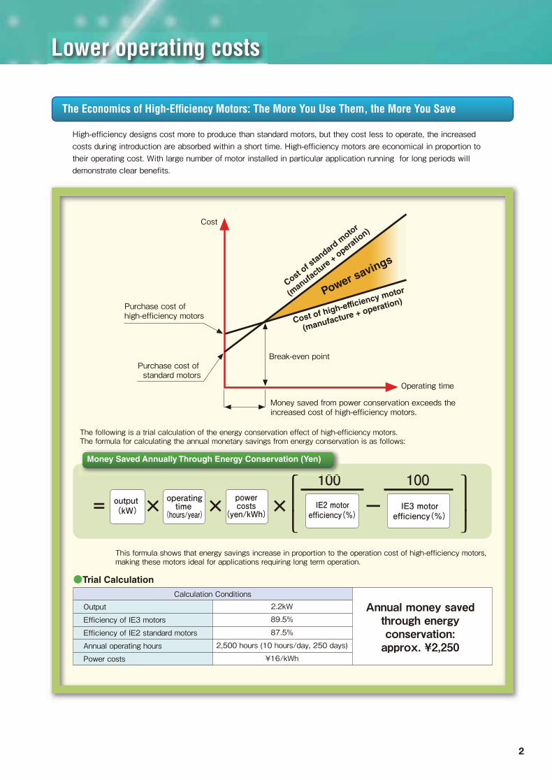
Lower operating costs
High-efficiency designs cost more to produce than standard motors, but they cost less to operate, the increased costs during introduction are absorbed within a short time. High-efficiency motors are economical in proportion to their operating cost. With large number of motor installed in particular application running for long periods will demonstrate clear benefits.
The Economics of High-Efficiency Motors: The More You Use Them, the More You Save
This formula shows that energy savings increase in proportion to the operation cost of high-efficiency motors, making these motors ideal for applications requiring long term operation.
The following is a trial calculation of the energy conservation effect of high-efficiency motors. The formula for calculating the annual monetary savings from energy conservation is as follows:
output (kW)
operatingtime
(hours/year)
powercosts
(yen/kWh)IE2 motorefficiency(%)
100 100
IE3 motorefficiency(%)
× × × -=100
Money Saved Annually Through Energy Conservation (Yen)
Cost of high-efficiency motor
(manufacture + operation)
Cost of s
tandard
moto
r
(manufa
cture
+ o
peratio
n)
Operating time
Money saved from power conservation exceeds theincreased cost of high-efficiency motors.
Break-even point
Cost
Purchase cost ofhigh-efficiency motors
Purchase cost of standard motors
Power savings
Calculation Conditions
●Trial Calculation
Annual money savedthrough energyconservation:approx. ¥2,250
2.2kW
89.5%
87.5%
2,500 hours (10 hours/day, 250 days)
¥16/kWh
Output
Efficiency of IE3 motors
Efficiency of IE2 standard motors
Annual operating hours
Power costs

Motor characteristics are changing.
3
The external shape and motor characteristics are changing.
0.75kW
1.5kW
2.2kW
φ162
φ186
φ186
□156
□178
□192
Capacity IE3Current product
Top runner motors control efficiency losses to run at a faster speed than standard motors. When a standard motor is switched with a high-efficiency motor, the motor output will increase due to higher speeds. Motor efficiency is high, but the increase in output can result in greater energy consumption, so if high-efficiency motors are used in applications for which the speed cannot be increased, you might have to review reduction ratio.
Notes regarding the adoption of top-runner motors
The shape of the fan cover is changing.
The mounting dimensions are not changing.
●Motor speed
● The external shape is changing.
Top runner motors sometimes have lower coil resistance in order to reduce copper losses (primary and secondary), so the start-up current draw may be higher than with standard motors, and it might become necessary to change your breakers or other circuitry. If your motors start and stop with great frequency or the inertial moment is high, you will have to choose your motor type with regard to service factors (load coefficient).
●Electric current, start-up torque, and maximum torque

4
Motor characteristics: comparison chart
200V/50Hz
200V/60Hz
220V/50Hz
220V/60Hz
380V/50Hz
380V/60Hz
400V/50Hz
400V/60Hz
440V/60Hz
200V/50Hz
200V/60Hz
220V/50Hz
220V/60Hz
380V/50Hz
380V/60Hz
400V/50Hz
400V/60Hz
440V/60Hz
200V/50Hz
200V/60Hz
220V/50Hz
220V/60Hz
380V/50Hz
380V/60Hz
400V/50Hz
400V/60Hz
440V/60Hz
0.75kW
1.5kW
2.2kW
Voltage/
frequencyRated current (A) Start-up current (A) Start-up torque (%) Stopping torque (%)
Current characteristics Torque characteristicsEfficiency (%)
Rated rotation speed
(r/min)
1420
1690
1410
1710
1410
1710
1420
1710
1720
1440
1730
1440
1750
1450
1740
1450
1750
1760
1460
1750
1440
1750
1430
1750
1440
1730
1740
1440
1720
1430
1740
1430
1740
1440
1730
1740
1450
1740
1430
1750
1440
1740
1450
1740
1750
1450
1740
1450
1750
1440
1750
1450
1740
1750
3.5
3.2
3.1
3.1
1.75
1.75
1.7
1.6
1.5
6.8
6.1
5.8
5.9
3.55
3.4
3.6
3.2
3.1
9.9
9.0
8.1
8.7
4.9
4.7
4.9
4.5
4.3
3.2
3.0
2.9
2.9
1.65
1.6
1.6
1.5
1.4
6.4
6.0
5.39
5.7
3.3
3.28
3.2
3.0
2.85
8.8
8.4
7.4
7.9
4.5
4.2
4.35
4.15
3.9
19.1
17.1
15.2
19.4
8.59
11.30
9.16
8.25
9.25
42.0
37.0
34.5
41.2
22.1
22.1
23.7
21.0
23.3
58.8
53.2
49.2
57.3
29.8
31.3
32.0
28.0
31.7
19.1
16.6
15.9
18.6
9.0
10.8
9.6
8.3
9.3
43.5
36.0
33.9
40.3
21.7
21.6
23.1
18.6
20.7
58.5
47.0
49.5
52.5
30.0
28.7
32.0
25.0
28.0
267
231
242
307
245
275
279
218
273
236
190
217
225
227
200
265
204
251
227
180
239
222
204
200
242
180
252
246
190
218
224
221
201
249
193
243
243
190
197
221
206
196
231
190
219
236
180
245
222
209
200
234
180
210
325
290
289
363
283
360
316
281
349
310
270
292
328
322
297
359
312
390
319
267
311
343
300
303
349
297
359
305
261
282
321
276
318
308
263
323
338
283
274
348
302
315
337
280
335
337
278
317
336
306
297
341
270
331
79.6
82.5
79.6
82.5
78.0
82.5
79.6
81.0
82.5
82.8
84.0
82.8
84.0
82.0
84.0
82.8
84.0
84.0
84.3
85.6
84.3
87.5
84.3
87.5
84.3
86.3
87.5
85.3
85.5
82.5
86.5
84.6
85.5
85.3
85.7
86.6
87.1
87.6
85.3
88.2
86.7
86.5
86.9
87.7
88.3
89.2
89.5
86.7
89.8
88.9
89.5
89.3
89.5
90.1
IE3IE2 IE2 IE2 IE2 IE2 IE2IE3 IE3 IE3 IE3 IE3
Capacity
1. The output shaft allowable torque and allowable O.H.L. are unchanged.2. Contact us about other voltages and frequencies.
5
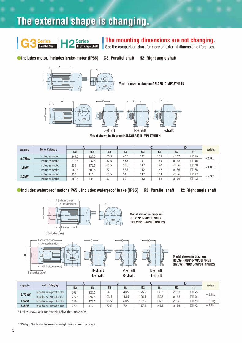
The external shape is changing.
The mounting dimensions are not changing.See the comparison chart for more on external dimension differences.
Model shown in diagram:G3L28N10-MP08TNNTN
Model shown in diagram:
G3L28S10-WP08TNNEN
(G3L28S10-WP08TNNEB2)
Model shown in diagram:
H2L32(HMB)10-WP08TNNEN
(H2L32(HMB)10-WP08TNNEB2)
Includes motorIncludes brakeIncludes motorIncludes brakeIncludes motorIncludes brake
0.75kW
A B C D
1.5kW
2.2kW
Motor Category
209.5216.5239260.5279300.5
227.5237.5276.5301.5310335
50.557.565.58765.587
43.553.563.588.56489
131131142142142142
135135142142153153
φ162φ162φ186φ186φ186φ186
□156□156□178□178□192□192
+2.9kg
+3.3kg
+5.7kg
IE3 IE2 IE2 IE2IE3 IE3 IE3Capacity
Includes waterproof motorIncludes waterproof brakeIncludes waterproof motorIncludes waterproof motor
A B C D
208277.5239279
227.5297.5276.5310
54123.5 70.5 70.5
48.5118.5 68.5 70
126.5126.5137.5137.5
130.5130.5137.5148.5
φ162φ162φ186φ186
□156□156□178□192
G3SeriesParallel Shaft H2Series
Right Angle Shaft
●Includes waterproof motor (IP65), includes waterproof brake (IP65) G3: Parallel shaft H2: Right angle shaft
●Includes motor, includes brake-motor (IP65) G3: Parallel shaft H2: Right angle shaft
* Brakes unavailable for models 1.5kW through 2.2kW.
* “Weight” indicates increase in weight from current product.
Model shown in diagram:H2L32(LRT)10-MP08TNNTN
AB C
D
L-shaft R-shaft T-shaft
C CAB
D
C
CA (includes brake)
A (includes motor)
D
CCC
D
Weight
L-shaft R-shaft T-shaftH-shaft M-shaft B-shaft
+2.9kg
+3.3kg+5.7kg
B (includes brake)
B (includes motor)
A (includes brake)A (includes motor)
B (includes brake)
B (includes motor)
IE2
IE3 IE2 IE2 IE2IE3 IE3 IE3IE2Motor CategoryCapacity Weight
0.75kW
1.5kW
2.2kW

6
The mounting dimensions are not changing.See the comparison chart for more on external dimension differences.
Model shown in diagram:
FS45N10-MP08TNNTN
Model shown in diagram:
FS45S10-WP08TNNEN
(FS45S10-WP08TNNEB2)
Model shown in diagram:
FF40(LRT)10-EP08TNNTN
F SeriesHollow Shaft / Solid Shaft F3Series
Concentric Hollow Shaft / Concentric Solid Shaft
●Includes motor, includes brake-motor FS: Hollow shaft F3S: Concentric hollow shaft
●Includes motor, includes brake-motor FF: Solid shaft F3F: Concentric solid shaft
●Includes waterproof motor (IP65), includes waterproof brake (IP65) FS: Hollow shaft F3S: Concentric hollow shaft
FF (solid shaft) only 0.75Kw.
Model shown in diagram:
F3S35N10-MP08TNNTN
Model shown in diagram:
F3S35S10-WP08TNNEN (F3S35S10-WP08TNNEB2)
Model shown in diagram:
F3F32(LRT)10-EP08TNNTN
A
B
C
D
A
B
C
D
C
D
C
D
A
B
C
D
A
B
C
D
A (includes brake)A (includes motor)
B (includes brake)
B (includes motor)
B (includes brake)
B (includes motor)
A (includes brake)A (includes motor)
Includes motorIncludes brakeIncludes motorIncludes brakeIncludes motorIncludes brake
A B C DMotor Category
209.5216.5239260.5279300.5
227.5237.5276.5301.5310335
50.557.565.58765.587
43.553.563.588.56489
131131142142142142
135135142142153153
φ162φ162φ186φ186φ186φ186
□156□156□178□178□192□192
+2.9kg
+3.3kg
+5.7kg
IE3 IE2 IE2 IE2IE3 IE3 IE3Capacity Weight
IE2
Includes waterproof motorIncludes waterproof brakeIncludes waterproof motorIncludes waterproof motor
A B C D
208277.5239279
227.5297.5276.5310
54123.5 70.5 70.5
48.5118.5 68.5 70
126.5126.5137.5137.5
130.5130.5137.5148.5
φ162φ162φ186φ186
□156□156□178□192
+2.9kg
+3.3kg+5.7kg
IE3 IE2 IE2 IE2IE3 IE3 IE3IE2Motor CategoryCapacity Weight
* Brakes unavailable for models 1.5kW through 2.2kW.
0.75kW
1.5kW
2.2kW
0.75kW
1.5kW
2.2kW
0.75kW
1.5kW
2.2kW

7
Model codes are changing.
Reduction gear unit The motor unitG3L28N10 MP08TNNT B2
●Parallel shaft (foot mount)
• 0.75kW • 200V/50Hz, 200V/60Hz, 220V/60Hz • Reduction ratio: 1/80 • Waterproof motor (output shaft material: SUS420J2) • With 200V brake
●Right angle shaft (foot mount)
●Hollow shaft (flange mount)
●Concentric solid shaft (flange mount)
* See the product model codes on the next page for more details.
●Table of model code changes (examples)
Brake
Series
① ② ③ ④ ⑤ ⑥ ⑦ ⑧ ⑨ ⑩ ⑪ ⑫ ⑬
G3
H2
H2
F
F3
L
L
S
S
F
28
50
55
35
40
N
M
N
N
T
M
W
W
M
M
10
80
100
12
7
P
P
P
P
P
08
08
15
22
15
T
T
T
T
T
Mount type Frame No.Shaft
arrangement/material
Reductionratio
Phase Voltage StandardMotorcategory
W
N
N
B
F
C
N
N
C
K
T
E
E
T
T
N
B2
N
B2
N
Capacity BrakeTerminalbox
Motorspecifications
Series
G3
H2
H2
F
F3
L
L
L
S
F
28
40
50
55
40
N
R
T
N
T
HE
HE
HE
HE
HE
10
80
100
12
7
M
V
G
B
M
075
075
150
220
150
T
T
T
T
T
Mounting type Frame No.Shaft
arrangementReduction
ratioPhase Voltage Specification
codeMotor
version
W
N
N
B
F
C
N
N
C
K
T
E
E
T
T
Capacity Terminalbox
Motorcategory
• 0.75kW • 380V/50Hz (CCC-certified for China) • Reduction ratio: 1/10 • No brake
• 2.2kW • 220V/50Hz (for China) • Reduction ratio: 1/12.5 • With 200V brake
• 1.5kW • 380V/60Hz (for S. Korea) • Reduction ratio: 1/7.5 • No brake
• 1.5kW • 200V/50Hz, 200V/60Hz, 220V/60Hz • Reduction ratio: 1/100 • Waterproof motor (output shaft material: S43C) • No brake
●Right angle shaft (foot mount)
Main changes・ Models are differentiated according to reducer, motor, and brake specifications.・Waterproof (IP65: output shafts made of SUS) and outdoor (IP65: output shafts made of S43C) motor categories have been combined into waterproof motors, and models are differentiated according to output shaft material code.・Representation of the motor capacity changes. 0.75kW:075→08 1.5kW:150→15 2.2kW:220→22
Series name (reducer type)Mount type (foot, flange)Frame No. (output shaft diameter)Output shaft arrangement code. Categorized by material.Standard motor: Parallel shaft and hollow shaft are N. Right angle shaft has arrangement codes L, R or T.Waterproof motor: If output shaft material is S43C, parallel shaft is N; right angle and solid shaft have arrangement codes L, R or T.Waterproof motor: If output shaft material is SUS420J2, parallel shaft and hollow shaft are S; right angle shaft has arrangement codes H, M or B.(Note: Because codes are differentiated according to output shaft material, waterproof motor and outdoor motor categories are not differentiated; all are classified as waterproof motors.)Reduction ratio (Note that 1/7.5 is shown as 7, and 1/12.5 is shown as 12.)Note that motor categories are divided according to motor type and the presence of brakes.Premium high-efficiency IE3This code is changing. 0.75kW: 075 → 08 1.5kW: 150 → 15 2.2kW: 220 → 22Phase has been given a code.Voltage has been given a code.StandardThis specifies the terminal box code.Brake type has been given a code. If there is no brake, the code is N.
(1)(2)(3)(4)
(5)(6)(7)(8)(9)(10)(11)(12)(13)

Model codes
Parallel shaftRight angle shaftHollow shaft / solid shaftConcentric hollow shaft / concentric solid shaftFoot mount (G3, H2)Flange mount (G3), solid shaft (F), concentric solid shaft (F3)Small flange mount (G3) (frames 28 and 32 only)Hollow shaft (F), concentric hollow shaft (F3)
Series
G3 L N M P T N N T528 08 T9HZXB2
① ② ④ ⑥ ⑦ ⑨ ⑩ ⑪ ⑫⑤③ ⑧ ⑮⑭⑬
Motorcategory
Motorspec
Terminalbox
Box position,power lead positionVoltage
Shaftarrangement/
materialMount Frame No.
Gear head model
Reducer
Motor model
Brake model
Supplemental
code
Supplemental
number
Motor model
Product model
Capacity Standard Supplementalcode
* Indicated in supplemental number space on name plate
Brake
Options
PhaseReductionratio
NS
Parallel shaft,hollow shaft,concentrichollow shaft
Right angle shaft, solid shaft, concentric solid shaft
LH
RM
TB
Material: S43C
Material: SUS420J2
Shaft type
Standard induction motor (IP44)Waterproof induction motor (IP65)IE3 efficiency (Premium Efficiency)0.75kW1.5kW2.2kWThree-phase
G3H2FF3LFKS
①Series
②Mount
③Frame No.
Shaft
arrangement/
material
⑤Reduction ratio
⑥Motor category
⑦ Motor specifications
⑧Capacity
⑨Phase
⑩Voltage
⑪Standard
⑫ Terminal box
⑬Brake
⑭Supplemental code
⑮Terminal box position indicator number,
rectifier wiring specification number
Three-phase
8
N
W
FBNKC
::::::::
MWP081522T
:::::::
:::
:
:
::
Type T terminal box (steel)Type E terminal box (aluminum) (specifically for waterproof motors) No brake200V brake400V brake200V brake with manual release mechanism400V brake with manual release mechanismWaterproof 200V brakeWaterproof 400V brakeStandard specifications Code to indicate addition of special specifications
TENB2B4J2J4V2V4BlankX
:::::::::::
Output shaft diameter (inner diameter for hollow shafts, outer diameter for other types)
5: 1/5 ‒ 450: 1/450 (for example, 7 = 1/7.5, 12 = 1/12.5, 200 = 1/200)
Note 1: Brake lead wires run into the terminal box as standard.
Standard Voltage 200V/50Hz(for Chinese and European efficiency regulations), 200V/60Hz220V/60Hz(for South Korean efficiency regulations)
Double Voltage
Non-Standard VoltageNon-Standard Voltage
380V/50Hz(for Chinese and European efficiency regulations), 400V/50Hz(for European efficiency regulations), 400V/60Hz,440V/60Hz(for South Korean efficiency regulations)380V/60Hz(for South Korean efficiency regulations)220V/50Hz(for Chinese efficiency regulations)
Standard (for Japan and Europe)For South KoreaFor China
L: Seen from the input shaft side,the output shaft protrudes on the left.
R: Seen from the input shaft side, the output shaft protrudes on the right.
T: Seen from the input shaft side, the output shaft protrudes on both sides.
④

9
3-phase 0.75kW
Model Frame No. Reduction ratio
1/501/401/30
1/251/20
1/2001/1601/120
1/151/101/5
1/100
1/1001/801/60
1/4501/3751/300
28
40
32
50
1/501/401/30
1/251/20
1/2001/1601/120
1/151/101/5
1/100
1/1001/801/60
32
50
40
1/501/401/30
1/251/201/151/101/5
1/1001/801/60
40
503-phase 2.2kW
4P motor capacity
3-phase 1.5kW
(Notes) 1.
2.3.4.5.
The G3 series comes in three types: foot mount, flange mount, and small flange mount. (Small flange mount is available for frames 28‒32 only.)Ratios outlined in indicate models with torque limits. Please take careful note of the allowable torque in the characteristics table.Outdoor gear motors have been combined into waterproof gear motors.Reducer types may vary according to model.See our GTR Mid Series catalog for more details.
(Notes) 1.
2.3.4.
Ratios outlined in indicate models with torque limits. Please take careful note of the allowable torque in the characteristics table.Outdoor gear motors have been combined into waterproof gear motors.Reducer types may vary according to model.See our GTR Mid Series catalog for more details.
1/501/401/301/251/201/151/101/5
1/6032
3-phase 0.75kW 1/1201/1001/80 1/2401/2001/16040
1/4501/3751/30050
RT
L
RT
L
RT
L
1/501/401/301/251/201/151/101/5
1/6040
1/1201/1001/80 1/2401/2001/16050
RT
L
1/501/401/301/251/201/151/101/5
1/60 1/80 1/100 1/12050 R
T
L
RT
L
4P motor capacity and equivalent capacity
Output shaft arrangement
Reduction ratio
G3Series
H2 Series
G3L (foot mount) / G3F (flange mount) / G3K (small flange mount)
(option)
Our model make-up is not changing.
Gear motor
Gear motor w/ brake and
manual release
Waterproofgear motor
Waterproof gear motor
w/ brake
Gear motor w/ brake
Model
3-phase 2.2kW
3-phase 1.5kW
H2L (foot mount)
Frame No.
(option)
Gear motor
Gear motor w/ brake and
manual release
Waterproofgear motor
Waterproof gear motor
w/ brake
Gear motor w/ brake

10
(Notes) 1.
2.3.4.5.6.
Ratios outlined in indicate models with torque limits. Please take careful note of the allowable torque in the characteristics table.Frame numbers given in parentheses indicate solid shaft frame numbers.Outdoor gear motors have been combined into waterproof gear motors.Waterproof gear motors are available only with hollow shaft.Reducer types may vary according to model.See our GTR Mid Series catalog for more details.
(Notes) 1.2.3.4.5.6.7.
These are small frame number types.Ratios outlined in indicate models with torque limits. Please take careful note of the allowable torque in the characteristics table.Frame numbers given in parentheses indicate solid shaft frame numbers.Outdoor gear motors have been combined into waterproof gear motors.Waterproof gear motors are available only with hollow shaft.Reducer types may vary according to model.See our GTR Mid Series catalog for more details.
Model Reduction ratio
3-phase 0.75kW1/300 1/375 1/450
45(40)
55
55
55
1/5 1/7.5 1/10 1/12.5 1/15 1/20 1/25 1/30 1/40
1/120 1/160 1/200 1/2401/50 1/60 1/80 1/100
1/5 1/7.5 1/10 1/12.5 1/15 1/20 1/25 1/30 1/40
1/120 1/160 1/200 1/2401/50 1/60 1/80 1/100
1/5 1/7.5 1/10 1/12.5 1/15 1/20 1/25 1/30 1/40
1/1201/50 1/60 1/80 1/100
FSeries
F3Series
FS (hollow shaft) / FF (solid shaft)
F3S (concentric hollow shaft) / F3F (concentric solid shaft)
30(28)
35(32)
35(32)
45(40)
45(40)
45(40)
3-phase 0.75kW
Model
3-phase 2.2kW
3-phase 1.5kW
3-phase 2.2kW
3-phase 1.5kW
Frame No.
Frame No. Reduction ratio
4P motor capacity
4P motor capacity
(Notes 1)
(Notes 1)
(option)
Gear motor
Gear motor w/ brake and
manual release
Waterproofgear motor
Waterproof gear motor
w/ brake
Gear motor w/ brake
(option)
Gear motor
Gear motor w/ brake and
manual release
Waterproofgear motor
Waterproof gear motor
w/ brake
Gear motor w/ brake

11
*Brushless DC gearmotors are not compatible with high-efficiency regulations.
High-Efficiency Brushless DC Gearmotors
Capacity Reduction Ratio
Mounting Category
Parallel Shaft G3 Right Angle Shaft H2 Hollow Shaft/Solid Shaft F Concentric Hollow Shaft/Solid Shaft F3
Mounting Category
PPPParallel Shaft G3 Right Angle Shaft H2 Hollow Shaft/Solid Shaft F Concentric Hollow Shaft/Solid Shaft F3
RoHS
Capacity Reduction Ratio Backlash Precision
Mounting CategoryParallel Shaft AG3 Right Angle Shaft AH2 Concentric Hollow Shaft/
Solid Shaft AF3
CCCaCapapa icicittyty RRRedddu tctiiion RRRa ititio BBBa kkckllla hhsh PP Pre iici iision
Mounting CategoryPPParallel Shaft AG3 Right Angle Shaft AH2 Concentric Hollow Shaft/
Solid Shaft AF3
Capacity Reduction Ratio Backlash Precision
Mounting CategoryParallel Shaft AG3 Right Angle Shaft AH2 Concentric Hollow Shaft/
Solid Shaft AF3
CCCapa iicitty RRRedddu tctiiion RRRa ititio BBBa kkckllla hhsh PP Pre iici iision
Mounting CategoryPPParallel Shaft AG3 Right Angle Shaft AH2 Concentric Hollow Shaft/
Solid Shaft AF3
IP65Compatible
IP65Compatible
RoHS
RoHS
Capacity Reduction Ratio Voltage
12V・24V・48VMounting Category
Right Angle Shaft VH Concentric Hollow Shaft/Solid Shaft VF3
p yCCCCaCaCapapapapa iicicicittytytytyp yp yp yp yp yp yp yp yp yp y RReReReddududu tctctctctiioioionnnn RRaRaRatitititioooo
RoHS
p yCCCaCaCapapapa iicicicittytytyp yp yp yp yp yp yp yp yp yp y RRReReRedddududu tctctctiiioioionnn RRRaRaRa ititititiooo gVVVoVoVolltltltltagagageeegggggggggg
12V・24V・48VMounting Category
Right Angle Shaft VH Concentric Hollow Shaft/Solid Shaft VF3
Parallel Shaft VG
Battery-Powered Gearmotors RoHS
30 arcmin(some models excluded)/Normal1/5 to 1/240(Parallel Shaft: 1/200)
30 arcmin(some models excluded)/Normal1/5 to 1/240(Parallel Shaft: 1/200)
100 to 750 W
50 to 400 W
0.1kW to 2.2kW
100 to 750 W
AC Servo Gearmotor AEF
Brushless DC gearmotor APQ
IPM Gearmotor
IncludesMotor
IncludesBrake
IncludesMotor
IncludesBrake
IncludesMotor
IncludesBrake
IncludesMotor
IncludesBrake
Outdoor Use (IP65)
1/5 to 1/240 (some models excluded)
1/5 to 1/1500 (some models excluded)
12
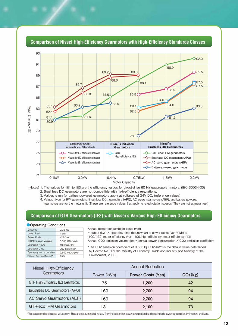
(Notes) 1.2.3.4.
The values for IE1 to IE3 are the efficiency values for direct-drive 60 Hz quadrupole motors. (IEC 60034-30)Brushless DC gearmotors are not compatible with high-efficiency regulations.Values given for battery-powered gearmotors apply at voltages of 24V DC. (reference values)Values given for IPM gearmotors, Brushless DC gearmotors (APQ), AC servo gearmotors (AEF), and battery-poweredgearmotors are for the motor unit. (These are reference values that apply to rated rotation speeds. They are not a guarantee.)
Comparison of Nissei High-Efficiency Gearmotors with High-Efficiency Standards Classes
Comparison of GTR Gearmotors (IE2) with Nissei’s Various High-Efficiency Gearmotors
●Operating ConditionsAnnual power consumption costs (yen)= output (kW) × operating time (hours/year) × power costs (yen/kWh) × {100/(IE2) motor efficiency (%) ‒ 100/high-efficiency motor efficiency (%)}Annual CO2 emission volume (kg) = annual power consumption × CO2 emission coefficient
0.75 kW1 unit¥16/kWh0.555 CO2/kWh10 hours/day250 days/year2,500 hours/year79%
*The CO2 emission coefficient of 0.555 kg CO2/kWh is the default value determined by Decree No. 3 of the Ministry of Economy, Trade and Industry and Ministry of the Environment, 2006.
*This data provides reference values only. They are not guaranteed values. They indicate motor power consumption but do not include power consumption by inverters or drivers.
GTR High-Efficiency IE3 Gearmotors
Brushless DC Gearmotors (APQ)
AC Servo Gearmotors (AEF)
GTR-eco IPM Gearmotors
Annual Reduction
Power (kWh) Power Costs (Yen) CO2(kg)
75
169
169
131
1,200
2,700
2,700
2,100
42
94
94
73
93
91
89
87
85
83
81
79
77
75
73
71
Motor E
fficiency (%)
Motor Capacity0.1kW 0.2kW 0.4kW 0.75kW 1.5kW 2.2kW
92.0
90.989.089.2
88.688.1
85.5
83.1
82.5
78.0
86.5
84.0
84.0
81.5
89.5
87.587.5
83.0
85.0
83.9
86.7
85.8
83.283.1
81.6
82.4
81.180.9
Efficiency underInternational Standards
Nissei’s InductionGearmotors
Nissei’sBrushless DC Gearmotors
Values for IE3 efficiency standards
Values for IE2 efficiency standards
Values for IE1 efficiency standards
GTR:High-efficiency, IE2
Nissei High-EfficiencyGearmotors
GTR-eco: IPM gearmotors
Brushless DC gearmotors (APQ)
AC servo gearmotors (AEF)
Battery-powered gearmotors
CapacityUnits UsedPower CostsCO2 Emission VolumeOperating HoursOperating DaysOperating Hours per YearEfficiency of Current Nissei Products (IE1)

13
Nissei High-Efficiency Gear Motors
IPM Gear motors
0.1kW~2.2kW
Parallel Shaft / Right Angle Shaft
Hollow Shaft / Solid Shaft
Concentric Hollow Shaft / Solid Shaft
Inverter for speedcontrol models: VF-nC3M
Speed Control
●Internal Motor Loss ComparisonNote: Applies to 0.75kW motors.Note: Applies to 0.75kW motors.250
200
150
100
50
0
Loss (W) Iron Loss
Mechanical Loss
Stray Load Loss
SecondaryCopper Loss
LossReduced
About 50%
PrimaryCopper Loss
GTR(Induction Gearmotor)
GTR-ECO(IPM Gearmotor)
●Efficiency Comparison90
85
80
75
70
65
60
550.1kW 0.2kW 0.4kW
Motor Capacity0.75kW 1.5kW 2.2kW
Efficiency (%)
IE2 Efficiency
Operation with InductionGearmotor and Inverter
Operation with IPM Gearmotorand Specialized Inverter
IPM is short for “interior permanent magnet”
and refers to motors with built-in magnets.
IPM i h f “i i ”
High-Efficiency IPM Gearmotor
High-Efficiency
Since electricity does not flow through the rotor, there is no
secondary copper loss.
Magnetic flux is generated by permanent magnets, so the
motor requires little electricity.
Efficiency clears IE3 at the motor unit level.
IE3 (Super-High Efficiency): IEC60034-30 induction motor efficiency level
The inverter unit’s rotational speed is set through output voltage
and current without using an encoder. In order to also achieve
optimal efficiency with an IPM motor, electrical current is reduced
to the minimum possible when a load is applied, resulting in an
IE2-surpassing efficiency rating, even including inverter loss.
IPM High-Efficiency Control
Energy-Saving
●Synchronous motor free from slips
Since it eliminates slips common on induction gear motors, the
motor runs at the specified frequency command, regardless of
load fluctuation.
●No need of dedicated cable
In comparison with a brushless DC motor having an equivalent
high efficiency, the wiring is simplified because no dedicated
cable is required. Signal cable is also eliminated because no
magnetic pole position sensor is used. Owing to these
features, the friendliness to environment has been enhanced to
the level comparable with induction motors. (By our compari-
son)
Elimination of dedicated cable and signal cable contributes to
the cost reduction.
Environmental friendliness plus ease of use!
Ease of use&
cost reduction
Without dedicated cableWithout hole element (Sensor-less)
Synchronous motor
Total cost reductionEnvironmental performance comparable
with induction gear motors
Specialized inverter
Magnetic pole position sensor
Rotation speed as specified by frequency

14
LIMIT
VF-nC3MOP-USB001Z
PC
Contact stop/contact thrust
functionWith the torque limiting function
Contact stop/contact thrust
It stops with the servo lock and then themechanical brake is applied.
With the simplified servo lock function
STOP
Stops exactly
It restricts torques generated by the motor in order to protect the mechanical system. (It cannot limit instantaneous torques.)・ Torque limit value can be switched in 2 steps via the input terminal.
High Level Device
Connect up to 31 terminals.
such as PLCs
110011001
By installing “PCM001Z”on your computer, it is possible to edit parameters and monitor status connecting our dedicated inverter to your computer
Monitor Status
Edit Parameters
①
Brake sequence function②
Simplified servo lock③
Torque limiting function④
RS 485 Interface included as Standard
⑤
Inverter Console Software [PCM001Z]⑥
Maintenance free by reducing abrasionon the mechanical brake!!
No need of brake for horizontal operation(Cost reduction)Frequency of start/stop is 30 times/min.
Easy to access through Inverter or Networkcommunications linksCommunication speed: Max 38.4 kbpsCan support Modbus RTU Protocol/ TOSHIBA Protocol ( Please contact us in case of using CC-Link or other Network Protocols)
・
・・

The specifications of the products in this catalogue are subject to change by modification or other reasons without notice, therefore, we recommend you to contact us for confirmation, before start designing.In case the end-user of products is military organization or the purpose of products is for manufacturing weapons, or the country you export products is the restricted country stipulated in the "Foreign Exchange and Foreign Trade Law", execute prior investigations and take proper measures for export.
*
*
Printed in August, 2014 ver.1
For orders and/or inquiries about products in this catalogue,please contact the dealer mentioned below:
■Overseas Sales SectionTEL:81-566-92-5312(Main switchboard)FAX:81-566-92-7002E-mail :oversea@nissei-gtr .co. jp
■Tokyo Branch Office 1-8 Nihonbashi Odenma-cho, Chuo-ku, Tokyo 103-0011 JapanTEL:81-3-5695-5411 FAX:81-3-5695-5418E-mail:[email protected]
■Osaka Branch Office 1-18 Ikutamamaemachi, Tennoji-ku, Osaka 543-0072 Japan TEL:81-6-6772-1900 FAX:81-6-6772-0406E-mail:[email protected]
■Chubu Branch Office 1-1 Inoue, Izumi-cho, Anjo-shi, Aichi 444-1297 JapanTEL:81-566-92-7410 FAX:81-566-92-7418E-mail:[email protected]
http://www.nissei-gtr.co.jp