High-Efficiency Furnace Installation Guide for Existing · PDF fileHIGH-EFFICIENCY FURNACE...
27
HIGH-EFFICIENCY FURNACE INSTALLATION GUIDE FOR EXISTING HOUSES Important Consideraons for Contractors and Homeowners This Guide was developed to provide contractors and homeowners with general informaon on best pracce approaches to installing high- efficiency (replacement) furnaces in exisng residenal and small commercial buildings.
Transcript of High-Efficiency Furnace Installation Guide for Existing · PDF fileHIGH-EFFICIENCY FURNACE...
HIGH-EFFICIENCY FURNACE INSTALLATION GUIDE FOR EXISTING HOUSESImportant Considerations for Contractors and Homeowners
This Guide was developed to provide contractors and homeowners with
general information on best practice approaches to installing high-
efficiency (replacement) furnaces in existing residential and small
commercial buildings.
DRAFT

Table of Contents
FOREWORD . . . . . . . . . . . . . . . . . . . . . . . . . . . . . . . . . . . . . . . . . . . . . . . . 3
OVERVIEW . . . . . . . . . . . . . . . . . . . . . . . . . . . . . . . . . . . . . . . . . . . . . . . . 4
HOMEOWNER SECTION . . . . . . . . . . . . . . . . . . . . . . . . . . . . . . . . . . . . . . . . 5
House as a system . . . . . . . . . . . . . . . . . . . . . . . . . . . . . . . . . . . . . . . . . . . . . 5
Hints and tips . . . . . . . . . . . . . . . . . . . . . . . . . . . . . . . . . . . . . . . . . . . . . . . 6
identifying quality installations . . . . . . . . . . . . . . . . . . . . . . . . . . . . . . . . . . . . 7
example quotation sheet . . . . . . . . . . . . . . . . . . . . . . . . . . . . . . . . . . . . . . . . . 8
CONTRACTOR SECTION . . . . . . . . . . . . . . . . . . . . . . . . . . . . . . . . . . . . . . . . . 9
steps to a better installation . . . . . . . . . . . . . . . . . . . . . . . . . . . . . . . . . . . . . . 9
Pre-changeout. . . . . . . . . . . . . . . . . . . . . . . . . . . . . . . . . . . . . . . . . . . . . . . 11
Installation. . . . . . . . . . . . . . . . . . . . . . . . . . . . . . . . . . . . . . . . . . . . . . . . . 13
commissioning. . . . . . . . . . . . . . . . . . . . . . . . . . . . . . . . . . . . . . . . . . . . . . . 16
education and maintenance . . . . . . . . . . . . . . . . . . . . . . . . . . . . . . . . . . . . . . . 17
challenges and solutions . . . . . . . . . . . . . . . . . . . . . . . . . . . . . . . . . . . . . . . . 18
example quotation sheet . . . . . . . . . . . . . . . . . . . . . . . . . . . . . . . . . . . . . . . . . 26
ADDITIONAL RESOURCES . . . . . . . . . . . . . . . . . . . . . . . . . . . . . . . . . . . . . . . 27
2 | HIGH-EFFICIENCY FURNACE INSTALLATION GUIDE FOR EXISTING HOUSES

ForewordThis Guide provides homeowners and HVAC contractors with general information on completing high-efficiency furnace retrofits. It provides an overview of key steps involved in the furnace retrofit process including pre-changeout, installation, commissioning, and education and maintenance. Additionally, common challenges encountered by HVAC contractors during furnace installation are covered with suggested solutions for overcoming these barriers discussed. This publication is not intended to replace residential furnace installation training materials developed for HVAC contractors.
AcknowledgementsThis publication was developed through consultation with many individuals and organizations involved in the residential furnace industry. This Guide would not have been possible without the support and guidance of FortisBC, the Province of British Columbia, the Thermal Environmental Comfort Association (TECA), the Heating, Refrigeration, and Air Conditioning Institute of Canada (HRAI), and Energy Star®. This Guide was prepared by RDH Building Science Inc. and Ecolighten Energy Solutions Ltd.
DisclaimerWhile care has been taken to confirm the accuracy of the information contained herein, the authors, contributors, funders, and publishers assume no liability for any damage, injury, or loss that may be incurred or suffered as a result of the use or reliance on the contents of this Guide. The views expressed here do not necessarily represent those of any individual contributor.
3 | HIGH-EFFICIENCY FURNACE INSTALLATION GUIDE FOR EXISTING HOUSES

OverviewA high-efficiency or “condensing” furnace can significantly reduce energy consumption in a typical home; however, without a quality installation, the furnace may never deliver its expected energy savings. Energy Star® has found that new furnaces often do not perform to their rated efficiency with some systems suffering up to a 30% reduction in performance as a result of improper installation.1
Replacement furnaces, in particular, need special consideration because they must interact with existing ductwork and other building systems. Replacement installations with inadequate preparation and follow-up will not only affect energy savings, but can also influence equipment longevity and occupant comfort. For example, the American Society of Heating, Refrigerating, and Air-Conditioning Engineers (ASHRAE) estimates the average life expectancy of a new gas furnace to be 15 years, largely as a result of varying levels of installation quality.2 This is significantly less than the general industry consensus and the furnace lifespans specified by many manufacturers.
A recent study on furnace installation quality completed for FortisBC indicated that on average only 46% of important installation criteria were in compliance with best practices.3 This represents a large gap between expected and actual furnace performance. This Guide will attempt to address this gap by highlighting the most important steps and procedures needed to optimize the performance of replacement furnaces in existing houses. Note that the primary focus of this document is on specific measures that improve energy performance, occupant comfort, and equipment durability. Health and safety concerns are not covered; refer to your local building code, the Gas Safety Regulation under the BC Safety Standards Act, and materials from the BC Safety Authority for further information.
The gap between conventional and quality retrofit furnace installations represents a significant opportunity for industry players who promote and follow best practices. By identifying the key elements of excellent furnace retrofits, this Guide can be used as a tool to educate consumers on the advantages of quality installations, stimulating demand for contractors applying best practices. Some further advantages for contractors and consumers include:
¹ A Guide to Energy-Efficient Heating & Cooling, ENERGY STAR®, 2013, pg. 20.² ASHRAE Journal, October 2012, pg. 84.³ Quality Installation Study for Furnaces – Research Summary, Ecolighten Energy Solutions Ltd., 2013.
CONTRACTOR BENEFITS CONSUMER BENEFITSCompliance with future code, permit, and program changes
Greater utility bill savings
Differentiation of excellent from least-cost, low-quality installations
Better furnace performance (thermal comfort, noise reduction)
Improved client relationships leading to business opportunities
Increased furnace lifespan
4 | HIGH-EFFICIENCY FURNACE INSTALLATION GUIDE FOR EXISTING HOUSES

HOMEOWNER SECTION
House as a SystemBefore discussing the specific procedures needed for high quality furnace installation retrofits, it is important to discuss the connections between the heating system, the building enclosure (also called the envelope or ‘skin’), and other electrical and mechanical systems. Any change to one element in the building will have an impact on the furnace. For example, additional attic, wall or crawlspace insulation and/or new windows and air sealing can lower building heat loss; a lower capacity furnace may now be able to accommodate your building's heating demand.
At any given moment, heat is flowing through the building enclosure or being generated within it. The following graphic introduces some of the typical heat flows that exist at any given moment within a building. Changes that affect any one of these heat flows can influence building heating demand and, subsequently, the selection of your new furnace.
Figure 1: Common building heat flows
1. Solar radiation 2. Space heating 3. Appliances 4. Lighting 5. Fireplaces 6. Occupants 7. Windows and doors
8. Walls 9. Basement 10. Attic11. Dryer ducts12. Exhaust fans (ventilation system)13. Combustion appliance flues
CONDUCTIONCONVECTIONRADIATION COLD AIR INFILTRATION
1
7
8
213
10
12
5
6
4
3
9
11
5 | HIGH-EFFICIENCY FURNACE INSTALLATION GUIDE FOR EXISTING HOUSES
HOMEOWNER SECTION
Hints and Tips
#1 IMPACT OF OTHER ENERGY UPGRADESYour home’s heating demand is heavily influenced by other energy-related components in the building. Renovation projects that include building enclosure, ventilation, or control system improvements will have an impact on the sizing of your new furnace. Be prepared to discuss any past or future changes to your home with the furnace contractor when he/she arrives.
#2 KEY FURNACE INSTALLATION CRITERIAAlways ask the furnace contractor to include the following items when he/she provides you with a quotation:
• Heat load calculation to size the new furnace
• Double piped venting with combustion air taken from outside
• A condensate pipe connected to a drain or pump
• A high quality filter with a tight fitting cabinet door for easy filter replacement
• Furnace cabinet leveled to ensure condensate drainage
• Evaluation of orphaned DHW tank venting
Many of the above items can be reviewed visually allowing you to easily verify the quality of your furnace installation.
#3 BENEFITS OF A MATCHING THERMOSTAT AND WIRINGDid you know that many new gas furnaces have features that can only be unlocked if a matching thermostat and wiring are selected? Modern staged furnaces match their heating output to building heating demand more precisely than single-stage appliances. This can improve occupant comfort and increase energy savings. To fully achieve these benefits, the new thermostat must be able to communicate different heating levels to the staged furnace and the wiring must also be matched.
#4 MAINTAINING YOUR NEW FURNACERegular maintenance schedules are critical for reliable furnace operation. Frequent maintenance can increase the service life of your equipment and will save you money on your utility bills. Always ensure that key furnace components such as the filter are replaced correctly and in a timely manner. Set up a maintenance contract with your HVAC contractor to guarantee that equipment servicing is completed properly and on a regular basis.
6 | HIGH-EFFICIENCY FURNACE INSTALLATION GUIDE FOR EXISTING HOUSES

HOMEOWNER SECTION
Identifying Quality InstallationsSeveral important characteristics of quality furnace installations can be observed visually. The following images compare common industry practices against furnaces that have been installed according to best practices. The example quotation sheet on the next page can also be used as a tool to verify quality furnace installations.
Common Practice Quality
Furnace Venting
Condensate Removal
Furnace Filter
Thermostat & Wiring
A two pipe venting system should be installed that provides combustion air to the furnace directly from outside.
Acidic condensate should be drained or pumped directly into the plumbing system. Some jurisdictions require the condensate to be neutralized before entering the sewer line.
The filter cabinet must have an easy serviceable tight-fitting door. Filter selection can bediscussed with your contractor.
A thermostat should beselected to match the stage(s) of the new furnace. The thermostat wiring must also be matched.
7 | HIGH-EFFICIENCY FURNACE INSTALLATION GUIDE FOR EXISTING HOUSES

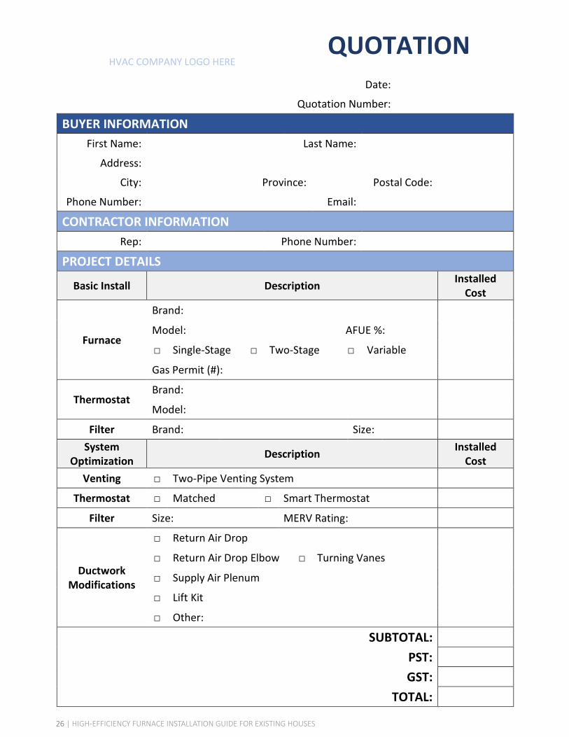
QUOTATION Date:
Quotation Number:
BUYER INFORMATION First Name: Last Name:
Address: City: Province: Postal Code:
Phone Number: Email:
CONTRACTOR INFORMATION Rep: Phone Number:
PROJECT DETAILS
Basic Install Description Installed Cost
Furnace
Brand:
Model: AFUE %:
□ Single-Stage □ Two-Stage □ Variable
Gas Permit (#):
Thermostat Brand:
Model:
Filter Brand: Size: System
Optimization Description Installed Cost
Venting □ Two-Pipe Venting System
Thermostat □ Matched □ Smart Thermostat
Filter Size: MERV Rating:
Ductwork Modifications
□ Return Air Drop
□ Return Air Drop Elbow □ Turning Vanes
□ Supply Air Plenum
□ Lift Kit
□ Other:
SUBTOTAL:
PST:
GST:
TOTAL:
HVAC COMPANY LOGO HERE
8 | HIGH-EFFICIENCY FURNACE INSTALLATION GUIDE FOR EXISTING HOUSES

CONTRACTOR SECTION
Steps to a Better InstallationBefore embarking on a furnace retrofit, it is important for the contractor to consider several items that will more generally influence the viability of the installation.
Firstly, thought should be given to codes, regulations, and permits in the local jurisdiction to ensure that health and safety considerations are addressed. Refer to B149.1 Natural Gas and Propane Installation Code, BC Building Code, and the BC Safety Authority4 for further information on health and safety regulations related to furnace installations. Worksafe BC regulated issues such as asbestos abatement can prevent a furnace installation from occurring if not mitigated beforehand and should also be reviewed.
Secondly, consideration should be given to the mechanical room layout/spacing and existing equipment as this may affect the viability of the furnace retrofit. In particular, some combustion appliances may be dependent on the existing furnace system for venting. These can include hot water tanks and other equipment related to the home HVAC system. In this case, hot water tank venting must be evaluated after the new furnace is installed to determine whether venting changes are required to accommodate an ‘orphaned’ domestic hot water tank.
Note that different furnace configurations will require subtle differences when it comes to installation, venting, draining, ducting, commissioning, and servicing. See below for typical furnace configuration options:
Figure 2: ‘Orphaned’ hot water tank
Figure 3: Typical furnace configurations
High-boy
Down-flow Horizontal
⁴ BC Safety Authority provides gas installation permits for most municipalities in British Columbia; however, seven municipalities issue there own permits and manage their own safety systems; more information is available at http://www.safetyauthority.ca/permits-approvals/installation-permits/gas
9 | HIGH-EFFICIENCY FURNACE INSTALLATION GUIDE FOR EXISTING HOUSES

CONTRACTOR SECTION
The furnace retrofit installation process can be separated into four discrete steps that will be outlined in the following sections. Generally, a homeowner will be interested in a high efficiency furnace retrofit when either an existing furnace fails or when other upgrades are being completed on the home. Follow the flowchart below to ensure that the necessary steps are followed for an excellent furnace retrofit installation.
Step 1: Pre-Changeout
An initial assessment of the existing furnace, exhaust and ducting system, and the overall house condition and occupancy is completed pre-quote in order to establish proper furnace sizing and any ducting modifications that must be made prior to installing the new furnace. This typically includes a heat load calculation for the house.
Step 2: Installation
These details are pertinent to the day of the new furnace installation. The furnace installation must meet all Code requirements and should be installed in a manner that maximizes performance, durability and occupant comfort. Ideally, the contractor should be member of TECA5 and/or HRAI6.
Step 3: Commissioning
Commissioning must be completed by a licensed gas fitter after the furnace is installed. At furnace start-up, the necessary commissioning tests are completed and recorded to ensure the furnace is operating according to the manufacturers specifications.
Step 4: Education and Maintenance
The homeowner is provided with the commissioning checklist and manufacturer’s information and then informed of the warranty and operation and maintenance procedures for the new furnace before the contractor leaves.
⁵ Thermal Environmental Comfort Association (TECA) provides guidelines and courses; more information is available at www.teca.com ⁶ Heating, Refrigeration and Air Conditioning Institute of Canada (HRAI) provides guidance and courses; more information is available at www.hrai.ca
10 | HIGH-EFFICIENCY FURNACE INSTALLATION GUIDE FOR EXISTING HOUSES
CONTRACTOR SECTION
Pre-ChangeoutBefore replacing existing furnace equipment, it is necessary to complete some tests and calculations as well as visually inspect the current system arrangement in order to accurately size the new furnace and consider changes in configuration, if needed. Furthermore, this pre-investigation may determine whether additional work beyond the localized furnace installation is needed (ductwork improvements, asbestos abatement). While there are several important action items that should be completed before installing the new furnace, three key items are discussed in detail below:
1 . Evaluation of Past or Future Home Upgrades
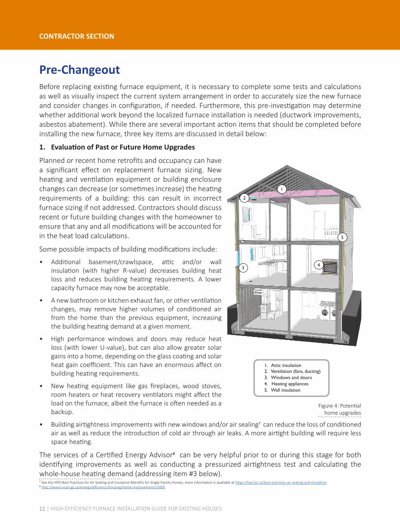
Planned or recent home retrofits and occupancy can have a significant effect on replacement furnace sizing. New heating and ventilation equipment or building enclosure changes can decrease (or sometimes increase) the heating requirements of a building: this can result in incorrect furnace sizing if not addressed. Contractors should discuss recent or future building changes with the homeowner to ensure that any and all modifications will be accounted for in the heat load calculations.
Some possible impacts of building modifications include:
• Additional basement/crawlspace, attic and/or wall insulation (with higher R-value) decreases building heat loss and reduces building heating requirements. A lower capacity furnace may now be acceptable.
• A new bathroom or kitchen exhaust fan, or other ventilation changes, may remove higher volumes of conditioned air from the home than the previous equipment, increasing the building heating demand at a given moment.
• High performance windows and doors may reduce heat loss (with lower U-value), but can also allow greater solar gains into a home, depending on the glass coating and solar heat gain coefficient. This can have an enormous affect on building heating requirements.
• New heating equipment like gas fireplaces, wood stoves, room heaters or heat recovery ventilators might affect the load on the furnace, albeit the furnace is often needed as a backup.
• Building airtightness improvements with new windows and/or air sealing7 can reduce the loss of conditioned air as well as reduce the introduction of cold air through air leaks. A more airtight building will require less space heating.
The services of a Certified Energy Advisor8 can be very helpful prior to or during this stage for both identifying improvements as well as conducting a pressurized airtightness test and calculating the whole-house heating demand (addressing item #3 below).⁷ See the HPO Best Practices for Air Sealing and Insulation Retrofits for Single-Family Homes; more information is available at https://hpo.bc.ca/best-practices-air-sealing-and-insulation⁸ http://www.nrcan.gc.ca/energy/efficiency/housing/home-improvements/5005
Figure 4: Potential home upgrades
1. Attic insulation 2. Ventilation (fans, ducting) 3. Windows and doors 4. Heating appliances 5. Wall insulation
1
2
43
5
11 | HIGH-EFFICIENCY FURNACE INSTALLATION GUIDE FOR EXISTING HOUSES

CONTRACTOR SECTION
2 . Assess Existing Ductwork
The existing ductwork should always be reviewed prior to completing a furnace retrofit. Most high efficiency furnaces need more cubic feet per minute (CFM) of air flow than existing furnace systems and the existing ductwork must be able to accommodate this extra air flow in order to function optimally. Furthermore, the ductwork for many existing systems may not even match the existing furnace system – an important consideration before proceeding with a retrofit. The contractor should always complete an external static pressure or ESP reading (measurement of duct friction) in order to determine whether the ductwork and fittings require modifications prior to installing the new furnace. Ductulator® calculations (see Figure 5) can be used to provide quick, general insight into the existing ductwork capacity. The ductwork system should be designed to have with an ESP reading in alignment with TECA or HRAI recommendations, once the new furnace is installed. Readings that fall outside this range indicate that the ductwork may need modifications; often duct air sealing and/or additional ductwork.
In situations where the existing ESP is very high and it is not possible to change or include any additional duct runs, the solution may be to select a high efficiency furnace that has a lower air flow, which is one BTU output category below the calculated heat load. In this case, an additional or supplementary heat source would then be required to meet the design temperature.
3 . Heat Load Calculations
Heat loss / heat gain calculations are the basis by which a new furnace is selected. In effect, all sources of heat loss (building enclosure, ventilation, etc.) are combined with sources of heat gain (occupants, appliances, heat recovery, etc.) in order to estimate the needed output of the furnace.
TECA and HRAI have explicit methodologies with worksheets and software for heat load calculations that should be used for furnace sizing to ensure that heat load estimates are completed appropriately.
Figure 6: Furnace sizing considerations
Heat Load Calculation Methodologies
TECA Quality First™ Forced Air Guidelines
HRAI Skilltech Academy Residential Heat Loss and
Heat Gain Manual
MECHANICAL EQUIPMENT
AIR INFILTRATION
LIGHTING
OCCUPANTS
SOLAR GAINS THROUGH GLAZING
AIR LEAKAGE
EXHAUST FANS ENCLOSURE
LOSSES
FURNACE FLUE
COLD AIRINFILTRATION
Figure 5: Duct sizing calculator
12 | HIGH-EFFICIENCY FURNACE INSTALLATION GUIDE FOR EXISTING HOUSES

CONTRACTOR SECTION
InstallationThe installation phase is where the furnace equipment is selected and integrated into the existing space heating system and ductwork. The Gas Safety Regulation (administered by the BC Safety Authority and seven municipalities) and the furnace manufacturers instructions will generally provide basic guidance on the furnace installation sequence and health and safety considerations. TECA and HRAI provide additional materials on the selection and installation of new furnace equipment (See Additional Resources section).
While there are several measures that have an impact on the performance of a new furnace installation, the following items are critical to ensuring the new equipment achieves the full energy-savings, comfort, and durability that the homeowner is expecting from the new furnace. The following is a summary of important considerations with locations indicated on the accompanying high-boy furnace graphic. Note that similar considerations are applicable to down-flow and horizontal furnaces; however, ducting and piping may be located at different locations due to differing configurations.
Figure 7: High-boy furnace install diagram
1. Tapered transition on return air drop 2. Sealed ductwork joints 3. Radius throat elbow and/or turning vanes 4. Sealed, accessible filter cabinet with quality filter 5. Furnace leveled to drain as per manufacturer’s specs 6. Matching thermostat and compatible wiring 7. Double pipe combustion venting
1
3
5
4
7
6
2
13 | HIGH-EFFICIENCY FURNACE INSTALLATION GUIDE FOR EXISTING HOUSES
CONTRACTOR SECTION
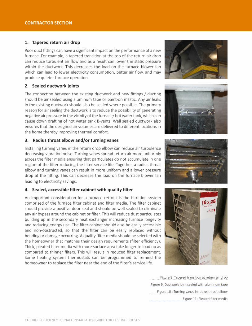
1 . Tapered return air drop
Poor duct fittings can have a significant impact on the performance of a new furnace. For example, a tapered transition at the top of the return air drop can reduce turbulent air flow and as a result can lower the static pressure within the ductwork. This decreases the load on the furnace blower fan which can lead to lower electricity consumption, better air flow, and may produce quieter furnace operation.
2 . Sealed ductwork joints
The connection between the existing ductwork and new fittings / ducting should be air sealed using aluminum tape or paint-on mastic. Any air leaks in the existing ductwork should also be sealed where possible. The primary reason for air sealing the ductwork is to reduce the possibility of generating negative air pressure in the vicinity of the furnace/ hot water tank, which can cause down drafting of hot water tank B-vents. Well sealed ductwork also ensures that the designed air volumes are delivered to different locations in the home thereby improving thermal comfort.
3. Radius throat elbow and/or turning vanes
Installing turning vanes in the return drop elbow can reduce air turbulence decreasing vibration noise. Turning vanes spread return air more uniformly across the filter media ensuring that particulates do not accumulate in one region of the filter reducing the filter service life. Together, a radius throat elbow and turning vanes can result in more uniform and a lower pressure drop at the fitting. This can decrease the load on the furnace blower fan leading to electricity savings.
4 . Sealed, accessible filter cabinet with quality filter
An important consideration for a furnace retrofit is the filtration system comprised of the furnace filter cabinet and filter media. The filter cabinet should provide a positive door seal and should be well sealed to eliminate any air bypass around the cabinet or filter. This will reduce dust particulates building up in the secondary heat exchanger increasing furnace longevity and reducing energy use. The filter cabinet should also be easily accessible and non-obstructed, so that the filter can be easily replaced without bending or damage occurring. A quality filter media should be selected with the homeowner that matches their design requirements (filter efficiency). Thick, pleated filter media with more surface area take longer to load up as compared to thinner filters. This will result in reduced filter replacement. Some heating system thermostats can be programmed to remind the homeowner to replace the filter near the end of the filter’s service life.
Figure 8: Tapered transition at return air drop
Figure 10 : Turning vanes in radius throat elbow
Figure 11: Pleated filter media
Figure 9: Ductwork joint sealed with aluminum tape
14 | HIGH-EFFICIENCY FURNACE INSTALLATION GUIDE FOR EXISTING HOUSES

CONTRACTOR SECTION
Figure 13: Programmable thermostat installed below existing thermostat
Figure 12: Leveled furnace cabinet
Figure 14: Double pipe combustion venting
5 . Proper furnace placement and leveling
High efficiency condensing furnaces produce acidic condensate during operation. This condensate must be effectively drained from the furnace or corrosion damage may occur. Most manufacturers recommend leveling the furnace to promote condensate drainage out of the system. Always refer to the manufacturer's leveling requirements before installation. An option is to install isolation vibration pads to help to level the furnace. The new furnace system should always be installed in a position that is easily accessible to facilitate future service.
6 . Matching thermostat and compatible wiring
Many new, high efficiency furnaces have the option of two or more stages of heat output (correlating to gas valve position) and have variable speed furnace blower motors. These new furnaces should be accompanied by a matching thermostat in order to take advantage of these variable heating and distribution outputs. A matching programmable thermostat may reduce energy use and produce more precise comfort levels by maintaining more consistent low-fire operation when heating demands are lower, limiting intermittent high-fire operation (short cycling) of the furnace. Low voltage thermostat (LVT) wiring should be utilized that matches the new thermostat having an appropriate number of wires.
7 . Double pipe combustion venting
It is highly recommended that new furnace installations be accompanied by a double pipe system with combustion air taken directly from the outside. This venting system provides more controlled combustion as ambient air in the mechanical room is no longer relied upon for combustion. Furthermore, any holes in the building enclosure that were previously used to provide combustion air can possibly be sealed (if they do no affect other naturally aspiring combustion appliances), decreasing air leakage heat loss and increasing occupant comfort (reduction in unwanted drafts). These changes improve overall home energy performance and increase the service life of the new furnace equipment. A two pipe system can reduce several common heating/ventilation issues including air leakage, incidence of unwanted smells, and equipment performance problems related to building depressurization.
15 | HIGH-EFFICIENCY FURNACE INSTALLATION GUIDE FOR EXISTING HOUSES

CONTRACTOR SECTION
CommissioningCommissioning is the process through which the new furnace system is verified and adjusted so that it performs per the manufacturer’s and owner’s requirements. Beyond visual inspection of components such as the filter media, a series of tests should be completed with the help of instrumentation (manometers, thermometers). The results of the testing are then compared against acceptable values (often manufacturer specified) in order to calibrate the new furnace and the information is recorded on a commissioning checklist (to be provided to the homeowner). Specific guidance on the procedures and equipment needed for commissioning is provided in TECA and HRAI documentation (See Additional Resources section).
A simplified commissioning process for the new furnace will include at least the following:
• Inspection of individual system components including filters, wiring, and gas lines.
• Complete a pressure check of the supply gas line "up stream" and manifold gas pressure "down stream" of the appliance gas valve. Adjust “down stream” manifold pressure as needed to meet the furnace manufacturer's nameplate value.
• Check the firing rate of the furnace by “clocking-the-meter”. The high-firing rate of the furnace must not be outside 10% of the rated BTU/hour input. Alternatively, the manifold orifice size can be determined in order to confirm the furnace rated BTU/hour input. In this case , the size of the orifice is visually determined by the drill size of the hole and the manifold pressure is then measured with a manometer. Together this information is used to determine the amount of gas that will flow into the burner.
• Calculate the furnace temperature rise by measuring the air temperature of the supply and return air, respectively. Confirm that the temperature rise lies within the manufacturer's stated tolerance. For example, on a two-stage gas valve furnace, the temperature rise should be taken at both high-fire and low-fire.
• Complete an external static pressure test (ESP) and confirm that the tested value is aligned with TECA or HRAI recommendations. Complete ductwork modifications as necessary. Refer to page 20 under solutions for both low and high ESP.
• Document all testing information on a commissioning checklist and record any outstanding issues for follow up with the homeowner.
Figure 15: Empirical tests for commissioning new furnace
16 | HIGH-EFFICIENCY FURNACE INSTALLATION GUIDE FOR EXISTING HOUSES

CONTRACTOR SECTION
Education and MaintenanceOne of the biggest factors in homeowner satisfaction with a new furnace system is the homeowners’ own understanding of how to operate and maintain the system. The contractor should facilitate this understanding and should clarify any owner responsibilities once the installation is complete. In addition, this action provides an opportunity for the contractor to propose a service plan for the new furnace.
Always provide the homeowner with all furnace related documentation and inform them of its location (e.g. furnace pocket) once the furnace is commissioned. Note that this is a Code requirement. The contractor should also demonstrate basic furnace operation and maintenance procedures in order to ensure that the homeowner is comfortable operating their new equipment. The following list includes documentation that should be provided and topics that should be reviewed / demonstrated with the homeowner before leaving the site:
• Manufacturer’s product literature (furnace, thermostat, filter)
• Warranty coverage of new furnace and thermostat including servicing requirements for compliance with warranty policy
• Commissioning checklist (empirical results from commissioning phase) - this data is also commonly recorded with a felt pen on the ductwork
• Contractor contact information for future maintenance
• Basic operation of the new furnace – new high efficiency furnaces generally have at least two operating options (low-fire, high-fire)
• Thermostat operation (demonstrate programming if applicable)
• Benefits of furnace optimization (energy savings, thermal comfort)
• Temperature set-back procedures
• Proper labeling of switches
• Maintenance
• Filter replacement – what products are acceptable (size, efficiency, etc.)
• Annual equipment servicing requirements
• Establishing a maintenance schedule
• Benefits of a maintenance contract versus year-by-year calls
Figure 16: The furnace pouch is an excellent location to
store furnace documentation
17 | HIGH-EFFICIENCY FURNACE INSTALLATION GUIDE FOR EXISTING HOUSES
CONTRACTOR SECTION
Challenges and SolutionsThere are a variety of challenges that can lead to poor performance in retrofit furnace installations. These challenged can result in higher energy consumption, decreased equipment longevity, and sub-optimal occupant comfort if not addressed. The following section outlines common challenges encountered by HVAC contractors and the suggested solutions for overcoming these barriers.
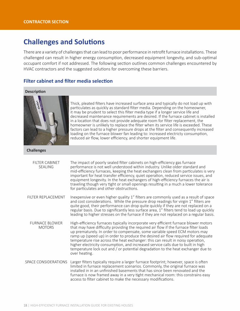
Filter cabinet and filter media selection
Description
Thick, pleated filters have increased surface area and typically do not load up with particulates as quickly as standard filter media. Depending on the homeowner, it may be prudent to select this filter media type if a longer service life and decreased maintenance requirements are desired. If the furnace cabinet is installed in a location that does not provide adequate room for filter replacement, the homeowner is unlikely to replace the filter when its service life is exceeded. These factors can lead to a higher pressure drops at the filter and consequently increased loading on the furnace blower fan leading to: increased electricty consumption, reduced air flow, lower efficiency, and shorter equipment life.
Challenges
FILTER CABINET SEALING
FILTER REPLACEMENT
FURNACE BLOWER MOTORS
SPACE CONSIDERATIONS
The impact of poorly sealed filter cabinets on high-efficiency gas furnace performance is not well understood within industry. Unlike older standard and mid-efficiency furnaces, keeping the heat exchangers clean from particulates is very important for heat transfer efficiency, quiet operation, reduced service issues, and equipment longevity. In the heat exchangers of high-efficiency furnaces the air is traveling though very tight or small openings resulting in a much a lower tolerance for particulates and other obstructions.
Inexpensive or even higher quality 1” filters are commonly used as a result of space and cost considerations. While the pressure drop readings for virgin 1” filters are quite good, their performance can drop quite quickly if they are not replaced on a regular basis. Due to significantly less surface area, 1” filters tend to load up quickly leading to higher stresses on the furnace if they are not replaced on a regular basis.
High-efficiency furnaces typically incorporate very efficient furnace blower motors that may have difficulty providing the required air flow if the furnace filter loads up prematurely. In order to compensate, some variable speed ECM motors may ramp up (speed up) in order to produce the desired air flow required for adequate temperature rise across the heat exchanger: this can result in noisy operation, higher electricity consumption, and increased service calls due to built in high temperature lock out and / or potential degradation to the heat exchanger due to over heating.
Larger filters typically require a larger furnace footprint; however, space is often limited in furnace replacement scenarios. Commonly, the original furnace was installed in in an unfinished basements that has since been renovated and the furnace is now framed away in a very tight mechanical room: this constrains easy access to filter cabinet to make the necessary modifications.
18 | HIGH-EFFICIENCY FURNACE INSTALLATION GUIDE FOR EXISTING HOUSES

CONTRACTOR SECTION
Filter cabinet accessibility and filter media selection (Continued)
Solutions
• Thicker, pleated filters have longer service lives and can reduce furnace maintenance requirements. When there are obstructions near the furnace cabinet, it is important to come up with a serviceable filter solution in order to protect and maintain the furnace.
• Space is rarely an issue in down-flow or horizontal flow furnace orientations. In up-flow furnace positions, there are a variety of options when limited installation space is available:
• The most common solution is to build a lift kit (sheet metal / ductwork) and install the filter at the furnace base.
• A second option is to locate the filter elsewhere in the return air drop ductwork.
• A third option is to move the domestic hot water tank or to move a wall (where possible) in order to accommodate the filter.
19 | HIGH-EFFICIENCY FURNACE INSTALLATION GUIDE FOR EXISTING HOUSES
CONTRACTOR SECTION
Thermostat and wiring compatibility
Description
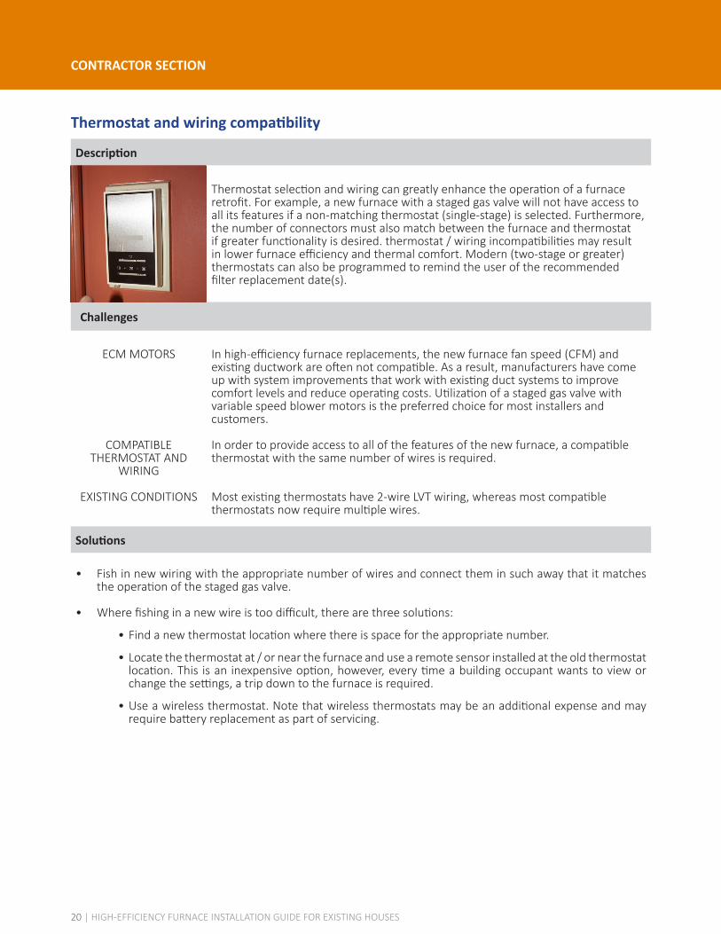
Thermostat selection and wiring can greatly enhance the operation of a furnaceretrofit. For example, a new furnace with a staged gas valve will not have access to all its features if a non-matching thermostat (single-stage) is selected. Furthermore, the number of connectors must also match between the furnace and thermostat if greater functionality is desired. thermostat / wiring incompatibilities may result in lower furnace efficiency and thermal comfort. Modern (two-stage or greater) thermostats can also be programmed to remind the user of the recommended filter replacement date(s).
Challenges
ECM MOTORS
COMPATIBLE THERMOSTAT AND
WIRING
EXISTING CONDITIONS
In high-efficiency furnace replacements, the new furnace fan speed (CFM) and existing ductwork are often not compatible. As a result, manufacturers have come up with system improvements that work with existing duct systems to improve comfort levels and reduce operating costs. Utilization of a staged gas valve with variable speed blower motors is the preferred choice for most installers and customers.
In order to provide access to all of the features of the new furnace, a compatible thermostat with the same number of wires is required.
Most existing thermostats have 2-wire LVT wiring, whereas most compatible thermostats now require multiple wires.
Solutions
• Fish in new wiring with the appropriate number of wires and connect them in such away that it matches the operation of the staged gas valve.
• Where fishing in a new wire is too difficult, there are three solutions:
• Find a new thermostat location where there is space for the appropriate number.
• Locate the thermostat at / or near the furnace and use a remote sensor installed at the old thermostat location. This is an inexpensive option, however, every time a building occupant wants to view or change the settings, a trip down to the furnace is required.
• Use a wireless thermostat. Note that wireless thermostats may be an additional expense and may require battery replacement as part of servicing.
20 | HIGH-EFFICIENCY FURNACE INSTALLATION GUIDE FOR EXISTING HOUSES

CONTRACTOR SECTION
Single pipe exhaust system
Description
Single pipe exhaust systems rely on air drawn from within the home for combustion. This often means that passive vents must be installed to provide makeup air for the furnace causing unnecessary heat loss. Furthermore, it is difficult to control furnace combustion in this configuration and this may cause poor system efficiency and lower equipment service life. There is also the risk of depressurizing the home if more air is exhausted than supplied: combustion gases can spill out of the furnace into the home threatening occupant safety.
Challenges
ROUTING
INSTALLATION DETAILS
PENETRATIONS
SIDE YARDS
Unlike a standard or mid-efficient B-vented furnace, a high-efficiency gas furnace requires PVC⁹ venting. Locating a 2-pipe route to the exterior can be challenging, particularly when the furnace is in the middle of a finished home.
Horizontal PVC venting must be supported every 6’ along the route.
Every venting route will ultimately penetrate the exterior vapour barrier, insulation and rain screen.
Some Authorities Having Jurisdiction (AHJs) do not allow side yard venting in close proximity to neighbouring houses.
⁹ Refer to Gas Directive Plastic Venting released by the BC Safety Authority for requirements for plastic vents; more information is available at http://www.safetyauthority.ca/alert/gas-directive-plastic-venting
21 | HIGH-EFFICIENCY FURNACE INSTALLATION GUIDE FOR EXISTING HOUSES

CONTRACTOR SECTION
Single pipe exhaust system (Continued)
Solutions
• There are three commonly used vent terminations and each has a preferred function. Note that BC Housing recommends venting combustion gases and terminating new vent pipes at the roof where possible¹⁰.
HORIZONTAL
The most common venting route is horizontally through the exterior wall. Finding a clear joist space or dropping the vent below the finished ceiling should be considered. A common solution is to remove the redundant combustion air pipe, so that this space can be used for PVC venting. In this case, a concentric vent termination kit can utilize the existing hole through the exterior wall. If the decision is to find a new route, a two hole penetration through the exterior wall can be terminated in two ways: with a termination kit flush to the wall or with two PVC pipes with elbows up and down to restrict exhaust air backdrafting through the combustion pipe.
VERTICAL
Another common venting route is through the ceiling or roof. This can be more easily achieved in single level ranchers or in two-storey homes by using the B-vent route through the floor above, particularly in situations where there is either no gas DHW tank or a condensing DHW is in place or being considered. When replacing the existing B-vent route, a concentric termination can be used at the existing B-vent flashing.
DOWN
A less common venting route is down and out - typically, this is used in a crawlspace application. Special drain / vent kits are needed to deal with condensation in this configuration, which are typically supplied by the manufacturer.
• Where the venting penetrates the exterior vapour barrier, insulation, and rainscreen, attention must be given to insulation repair, air sealing, and drip flashings to ensure that the venting does not compromise the building enclosure.
• In jurisdictions that do not permit side yard venting where the only route is horizontal, venting may have to exit the building enclosure and travel up the exterior of the building - often through a soffit, terminating above the roof. There are two considerations in this situation: the exterior venting must be insulated along its length and a custom, longer concentric vent termination will be needed to maintain a single flashing at the roof level. If options are limited, applications can be made to the AHJ for a variance and they may approve sidewall venting under certain circumstances.
¹⁰ See the BC Housing Builder Insight Bulletin #8: Sidewall Venting of Gas Appliances; more information is available at https://www.bchousing.org/publications/BuilderInsight10_SidewallVentingGasAppliances.pdf
22 | HIGH-EFFICIENCY FURNACE INSTALLATION GUIDE FOR EXISTING HOUSES

CONTRACTOR SECTION
Inadequate condensate removal
Description
During regular operation, condensing furnaces produce acidic condensate that can damage equipment if not drained properly from the furnace system. Furnace retrofits that are not leveled as per the manufacturer's recommendations and /or that have inadequate plumbing connections may have difficulty removing condensate effectively from the system. This can corrode furnace components and reduce equipment service life.
Challenges
INSTALLATION DETAILS High-efficiency furnaces must have provisions to drain condensate and Code requires that the condensate be removed via a warm (interior) drain upstream of a wet trap.
• Not all furnace locations have an accessible floor drain - this will necessitate a condensate pump.
• The condensate line can become crimped.
• Some AHJs require an acid neutralizer for the condensate.
Solutions
• The preference is to find a drain that does not require a pump. However, when a pump is required, there are minimal limitations on the condensate drain route. The drain piping material will often need to bend; therefore, it is important to avoid kinks.
• Always check with the AHJs to determine if an acid neutralizer is required for the condensate. If an acid neutralizer is installed, the limestone chips or other acid neutralizing substance must be replenished as part of regular maintenance.
23 | HIGH-EFFICIENCY FURNACE INSTALLATION GUIDE FOR EXISTING HOUSES

CONTRACTOR SECTION
Incorrect duct fittings
Description
Improperly sized or incorrect ducting components can lead to increased air turbulence in the duct system, which increases the load on the furnace blower fan. This may lead to increased electricity use, reduction in air flow, elevated noise, frequent replacement of the filter, and increased service requirements. Poorly designed and installed ducting can also reduce the distribution of heat within the home due to excessively high or low air pressures: this can lead to poor thermal comfort for building occupants.
Challenges
EXTERNAL STATIC PRESSURE
TESTING ACCESS
DEALING WITH RESULTS
NOTE: When taking measurements on the return air side, the numbers will come up as negative. However, since we are only concerned with the work (CFM) the blower has to deliver, these numbers are recorded as positive.
At the pre-changeout inspection, ESP measurements should be taken and used (as a guide) to determine the appropriate retrofit furnace sizing and to identify any ductwork modifications. The ESP measurements indicate whether the ductwork is capable of moving the quantity of air that is required for the new furnace to operate within the manufacturers specifications, distributing the heat reasonably evenly without excessive noise. Significant ESP improvements can be made by adjusting the ductwork directly adjacent the retrofit furnace.
In some furnace orientations (counter-flow), where the ductwork is in a slab or within the building structure, it is not possible to access the necessary ducting to take an ESP measurement. In this situation, count and measure the supply air and / or return air outlets and use a “Ductulator” (as a guide) to estimate the needed furnace sizing and ductwork modifications. Note that a combination of results is possible on both the supply side and the return side.
Possible results of the pre-changeout ESP may result in the following:
• ESP in close /proper range
• High ESP
• Low
24 | HIGH-EFFICIENCY FURNACE INSTALLATION GUIDE FOR EXISTING HOUSES

CONTRACTOR SECTION
Incorrect duct fittings (Continued)
Solutions
• Potential solutions for High ESP:
• Drop down furnace one BTU size (suggest supplementary heat).
• Add to the existing ductwork via a new supply/return duct.
• Dump supply air at the furnace via a spill grill.
• Potential solutions for Low ESP:
• After some discussion on comfort levels with the homeowner (occupant), adjust and partially close some of the return air grilles / supply air grilles in order to raise the ESP reading and then lock the grille dampers in position. Check if there are existing balancing dampers (typically near the furnace) which may be adjusted to increase static pressure. Recheck the ESP after all modifications.
25 | HIGH-EFFICIENCY FURNACE INSTALLATION GUIDE FOR EXISTING HOUSES
QUOTATION Date:
Quotation Number:
BUYER INFORMATION First Name: Last Name:
Address: City: Province: Postal Code:
Phone Number: Email:
CONTRACTOR INFORMATION Rep: Phone Number:
PROJECT DETAILS
Basic Install Description Installed Cost
Furnace
Brand:
Model: AFUE %:
□ Single-Stage □ Two-Stage □ Variable
Gas Permit (#):
Thermostat Brand:
Model:
Filter Brand: Size: System
Optimization Description Installed Cost
Venting □ Two-Pipe Venting System
Thermostat □ Matched □ Smart Thermostat
Filter Size: MERV Rating:
Ductwork Modifications
□ Return Air Drop
□ Return Air Drop Elbow □ Turning Vanes
□ Supply Air Plenum
□ Lift Kit
□ Other:
SUBTOTAL:
PST:
GST:
TOTAL:
HVAC COMPANY LOGO HERE
26 | HIGH-EFFICIENCY FURNACE INSTALLATION GUIDE FOR EXISTING HOUSES
Additional Resources• Quality First™ Basics of Air, 1st Edition, TECA, 2008.
Available at https://www.teca.ca/products.php?id=1
• Quality First™ Forced Air Guidelines Manual, 5th Edition, TECA, 2008. Available at https://www.teca.ca/products.php?id=2
• Residential Heat Loss & Heat Gain Manual, 5th Edition, HRAI, 2014. Available at http://www.hrai.ca/hraicatalogue.html
• Residential Air System Design Manual, 5th Edition, HRAI, 2014. Available at http://www.hrai.ca/hraicatalogue.html
• Residential Commissioning Manual, 2nd Edition, HRAI, 2004. Available at http://www.hrai.ca/hraicatalogue.html
• Builder Insight Bulletin #10: Sidewall Venting of Gas Appliances, BC Housing, 2013. Available at https://www.bchousing.org/publications/BuilderInsight10_SidewallVentingGasAppliances.pdf
• Gas Directive Plastic Venting, Directive No. D-G5 070628 5, British Columbia Safety Authority. Available at http://www.safetyauthority.ca/alert/gas-directive-plastic-venting
• Determining the required capacity of residential space heating and cooling appliances, CAN/CSA F280-12 (2012), Canadian Standards Association. Available at http://shop.csa.ca/en/canada/energy-efficiency/f280-12/invt/27006132012
• Natural gas and propane installation code, CAN/CSA B149.1-10 (2010), Canadian Standards Association. Available at http://shop.csa.ca/en/canada/natural-gas-and-propane-installation-codes/b1491-10-r2015/invt/27010992010
• ACCA Standard 5: HVAC Quality Installation Specification, ANSI/ACCA 5 (2010), Air Conditioning Contractors of America.
• ACCA Standard 9: HVAC Quality Installation Verification Protocols, ANSI/ACCA 9 (2011), Air Conditioning Contractors of America.
• ENERGY STAR Verified HVAC Installation (ESVI), Environmental Protection Agency and Department of Energy, 2016. Available at https://www.energystar.gov/index.cfm?c=hvac_install.hvac_install_index
• Specification for Energy-Efficient Installation and Maintenance Practices for Residential HVAC Systems, Consortium for Energy Efficiency, 2000.
27 | HIGH-EFFICIENCY FURNACE INSTALLATION GUIDE FOR EXISTING HOUSES