High-efficiency 3-phase induction motors for variable...
76
High-efficiency 3-phase induction motors for variable speed control LSMV 0.75 to 132 kW Technical catalogue 4981 en - 2013.09 / b
Transcript of High-efficiency 3-phase induction motors for variable...

High-efficiency 3-phase induction motors for variable speed control
LSMV0.75 to 132 kW
Technical catalogue4981 en - 2013.09 / b


3
C US
EN
Emerson Industrial Automation - LSMV high-efficiency induction motors for variable speed control - 4981 en - 2013.09 / b
A world-class product
LSMV high-efficiency 3-phase induction motors for variable speed control
Guaranteed variable speed performance
Emerson Industrial Automation is expanding its induction motor offer with a range specially adapted for variable speed. Combined with any type of frequency inverter, the LSMV offers solutions adapted to the industrial environment by producing electrical performance with IE2 efficiency level and mechanical performance by guaranteeing constant torque over a wide operating range without forced ventilation and without derating.
Interchangeability
The LSMV motor retains the IEC 60072-1 dimensions (frame size, mounting distance and shaft diameter) while an induction motor designed to operate on the mains would be derated according to the operating range.
Modularity and simplicity
In order to satisfy the demands of the process, the LSMV easily integrates speed sensors (incremental or absolute encoders, resolvers, bearing sensors, etc), as well as brakes and/or forced ventilation.

4 Emerson Industrial Automation - LSMV high-efficiency induction motors for variable speed control - 4981 en - 2013.09 / b
Contents
Index .....................................................................................5Designation...........................................................................6Description............................................................................7
SELECTIONChoice of application type .....................................................8Centrifugal machines, constant torque machines,constant power machines .....................................................84-quadrant machines ............................................................8Choice of number of poles, optional features and brake........9Choice of motor....................................................................10Motor performance as a function of the torqueand the speed range in S1 continuous duty..........................10
PERFORMANCELoad capacity of LSMV motors on a drive ............................11Selection tables for motors operating on the mains ..............222 poles - 3000 min-1 .............................................................224 poles - 1500 min-1 .............................................................236 poles - 1000 min-1 .............................................................24Using the motor at constant torque from 0 to 87 Hz ..............25Selection tables for motors operating on a driveusing 400 V 87 Hz ratio ........................................................262 poles - 3000 min-1 .............................................................264 poles - 1500 min-1 .............................................................276 poles - 1000 min-1 .............................................................27
MOTOR-DRIVE INSTALLATIONInstallation ...........................................................................28Influence of the mains supply ...............................................28Equipotential bonding ..........................................................28Connection of control cablesand encoder cables..............................................................28
MOTOR INSTALLATION AND OPTIONSAdaptation of the LSMV motor .............................................30Changes in motor performance............................................30Consequences of power supplied by drives .........................30Summary of recommended protection devices ....................31Reinforced insulation ...........................................................32Reinforced winding insulation ..............................................32Reinforced insulation of the mechanical parts ......................32Speed feedback ...................................................................33Selection of position sensor .................................................33Incremental encoders ..........................................................34Absolute encoders ...............................................................34D.C. tachogenerator ............................................................34Incremental and absolute encoder characteristics ...............35
Brake ...................................................................................36BK brake ..............................................................................36LSMV + BK brake characteristics .........................................38Forced ventilation unit ..........................................................39Thermal protection ...............................................................40Mains connection .................................................................41Cable glands ........................................................................41
DIMENSIONSShaft extensions ..................................................................42Foot mounted.......................................................................43Foot and flange mounted .....................................................44Flange mounted ...................................................................45Foot and face mounted ........................................................46Face mounted ......................................................................47Dimensions of optional features ...........................................48LSMV motors with optional features.....................................48Foot or flange mounted motors ............................................49Flange or foot and flange mounted motors ...........................49
CONSTRUCTIONExternal finish ......................................................................50Definition of atmospheres ....................................................50Definition of “Index of Protection” .........................................51Mounting arrangements .......................................................52Lubrication ...........................................................................53Permanently greased bearings ............................................53Bearings with grease nipples ...............................................53Axial loads ...........................................................................54Horizontal position ...............................................................54Vertical position (shaft facing down) .....................................55Vertical position (shaft facing up) .........................................56Radial loads .........................................................................57Standard fitting arrangement ...............................................57Special fitting arrangement ..................................................60Vibration level and maximum speeds ...................................62Motor vibration levels - Balancing ........................................62Vibration magnitude limits ....................................................63Mechanical speed limits for motors with variablefrequency .............................................................................63
GENERAL INFORMATIONQuality commitment .............................................................64Standards and approvals .....................................................65Approvals.............................................................................66Duty cycle - Definitions.........................................................67Identification ........................................................................70Configurator .........................................................................71Product availability ...............................................................71
LSMV high-efficiency 3-phase induction motors for variable speed control

5Emerson Industrial Automation - LSMV high-efficiency induction motors for variable speed control - 4981 en - 2013.09 / b
LSMV high-efficiency 3-phase induction motors for variable speed control
Absolute encoder................................................................. 34
Approvals........................................................................65-66
Axial load .....................................................................54 to 56
Balancing............................................................................. 62
Bearings ......................................................................53 to 61
Brake ...........................................................................36 to 38
Cable glands ........................................................................ 41
CE conformity ...................................................................... 65
Connection ..................................................................... 28-41
Construction ........................................................................ 50
CSA ..................................................................................... 66
Description............................................................................. 7
Designation............................................................................ 6
Dimensions of the LSMV..............................................42 to 47
Dimensions of the LSMV with its optional features .......... 48-49
Electrical characteristics ..............................................22 to 27
End shields ............................................................................ 7
External finish ...................................................................... 50
Fan cover ............................................................................... 7
Forced ventilation ................................................................ 39
Grease ................................................................................. 53
Housing with cooling fins........................................................ 7
Identification ........................................................................ 70
IEC.................................................................................. 65-66
Incremental encoder ............................................................ 34
Ingress protection ................................................................ 51
ISO 9001.............................................................................. 64
Labyrinth seals ...................................................................... 7
Lipseals ................................................................................. 7
Lubrication of bearings......................................................... 53
Mechanical speeds .............................................................. 63
Motor torque ........................................................................ 10
Mounting arrangements ....................................................... 52
Mounting type ...................................................................... 52
Nameplates ......................................................................... 70
Operating position................................................................ 52
Performance on a drive .........................................................11
Quality assurance ................................................................ 64
Radial load ...................................................................57 to 60
Reinforced insulation ........................................................... 32
Rotor ...................................................................................... 7
Selection ................................................................................ 8
Shaft .................................................................................... 42
Standards ....................................................................... 65-66
Stator ..................................................................................... 7
Terminal box ..................................................................... 7-41
Thermal protection ............................................................... 40
Torque characteristics .......................................................... 25
Vibration level ................................................................. 62-63
Index

6 Emerson Industrial Automation - LSMV high-efficiency induction motors for variable speed control - 4981 en - 2013.09 / b
LSMV high-efficiency 3-phase induction motors for variable speed control
Designation
4P1500 min-1 LSMV 180 M LS2/IE218.5 kW IM 1001
IM B3230 /400 V 50 Hz IP 55
No. of polesSpeed(s)
Frame sizeIEC 60072
Range/Efficiency class
Mains voltage
ProtectionIEC 60034-5
Series designation
Housing designation and manufacturer
code
Mounting arrangementIEC 60034-7
Mains frequency
IP 55Cl. F - ∆T 80 K
The complete motor reference described below will enable you to order the desired equipment.
The selection method consists of following the terms in the designation.
Rated power

7
1
2
3
4
5
6
7
8
9
10
Emerson Industrial Automation - LSMV high-efficiency induction motors for variable speed control - 4981 en - 2013.09 / b
Description
LSMV high-efficiency 3-phase induction motors for variable speed control
Description Materials Comments
Housing with cooling fins Aluminium alloy - with integral or screw-on feet, or without feet- die-cast for frame size ≤ 180- gravity die-cast for frame size ≥ 200 • 4 or 6 fixing holes for housings with feet • lifting rings for frame size ≥ 100- earth terminal with an optional jumper screw
Stator Insulated low-carbon magnetic steel laminationsElectroplated copper
- low carbon content guarantees long-term lamination pack stability- semi-enclosed slots- magnetic circuit based on acquired experience in frequency control- impregnation making it possible to withstand the sudden voltage variations caused by the high switching frequencies of IGBT transistor drives in accordance with IEC 34-17- class F insulation- thermal protection provided by 3 PTC probes (1 per phase)
Rotor Insulated low-carbon magnetic steel laminationsAluminium
- inclined cage bars- rotor cage pressure die-cast in aluminium (or alloy for special applications)- shrink-fitted to shaft and keyed for hoisting applications- rotor balanced dynamically, class B for frame size ≤ 132
Shaft Steel
End shields Cast iron - frame size 80 to 315
Bearings and lubrication - permanently greased bearings frame size 80 to 225- regreasable bearings frame size 250 to 315- bearings preloaded at non drive end
Labyrinth seal Lipseals
Plastic or steelSynthetic rubber
- lipseal or deflector at drive end for all flange mounted motors- lipseal, deflector or labyrinth seal for foot mounted motors
Fan Composite material - 2 directions of rotation: straight blades
Fan cover Pressed steel - fitted, on request, with a drip cover for operation in vertical position, shaft end facing down (steel cover)
Terminal box Aluminium alloy - fitted with a terminal block with steel terminals as standard (brass as an option)- terminal box fitted with plugs, supplied without cable glands (cable glands as an option)- 1 earth terminal in each terminal box- fixing system consisting of a cover with captive screws
1
2
3
4
5
6
7
8
9
10

8 Emerson Industrial Automation - LSMV high-efficiency induction motors for variable speed control - 4981 en - 2013.09 / b
LSMV high-efficiency 3-phase induction motors for variable speed controlSelection
Choice of application type
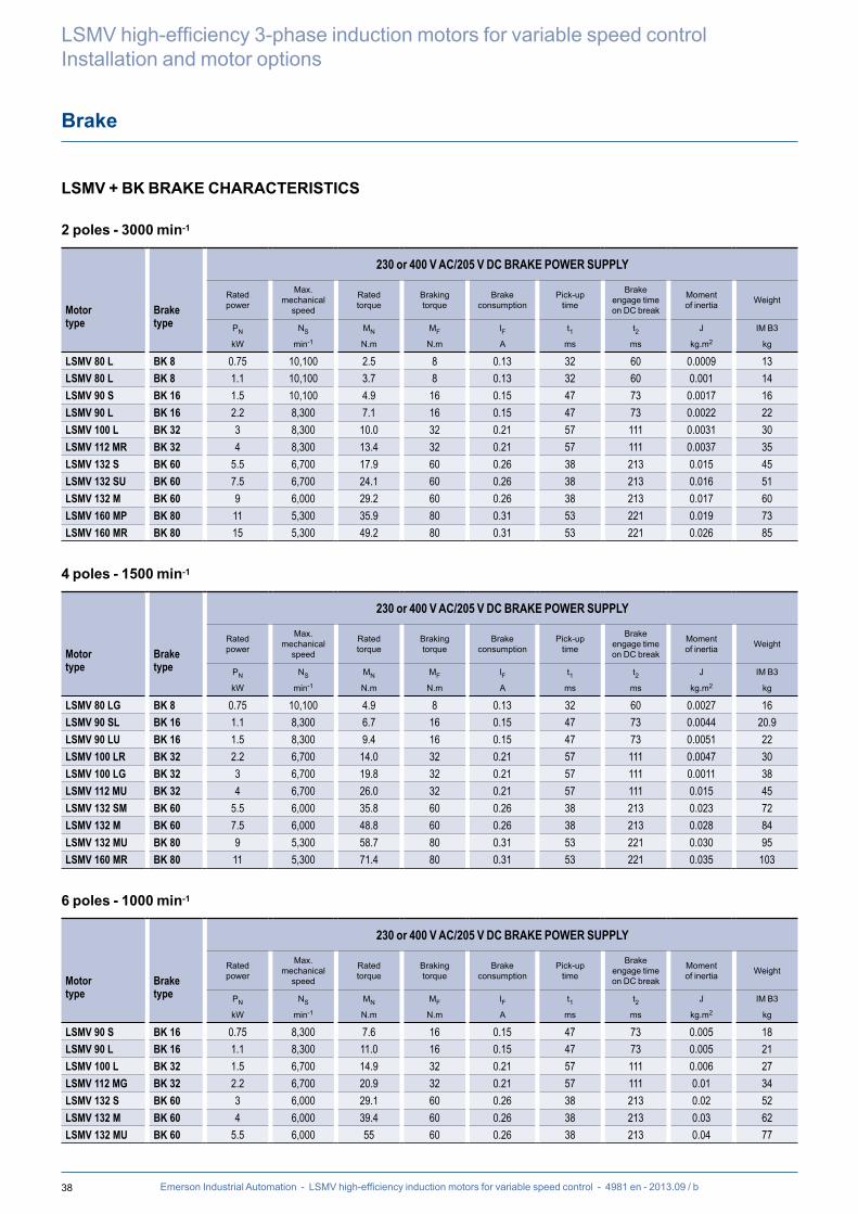
In principle, there are three typical types of load. It is essential to determine the speed range and the application torque (or power) in order to select the drive system:
CENTRIFUGAL MACHINESThe torque varies as the square of the speed (or cube of the power). The torque required for acceleration is low (about 20% of rated torque). The starting torque is low.
• Sizing: depends on the power or torque at maximum speed• Drive selected for normal duty
Typical applications: ventilation, pumping, etc
CONSTANT TORQUE MACHINESThe torque remains constant throughout the speed range. The torque required for acceleration may be high, depending on the machine (higher than the rated torque).
• Sizing: depends on the torque required over the entire speed range• Drive selected for heavy duty
Typical machines: extruding machines, grinders, travelling cranes, presses, etc
CONSTANT POWER MACHINESThe torque decreases as the speed increases. The torque required for acceleration is no more than the rated torque. The starting torque is at its maximum.
• Sizing: depends on the torque required at minimum speed and the range of operating speeds.
• Drive selected for heavy duty• An encoder feedback is advisable for improved regulation
Typical machines: winders, machine tool spindles, etc
4-QUADRANT MACHINESThese applications have a torque/speed operating type as described above, but the load becomes a driving load in certain stages of the cycle.
• Sizing: see above depending on the load• In the case of repetitive braking, install a reinforced insulation system (RIS)• Drive selection: to dissipate the power from a driving load, it is possible to use a
braking resistor, or to send power back to the grid. In the latter case, a regenerative or 4-quadrant drive should be used.
Typical machines: centrifuges, travelling cranes, presses, machine tool spindles, etc
Torque
Speed
nmin nmax
Power
Torque
Speed
nmin nmax
Power
Torque
Speed
nmin nmax
Power
Torque
Speed
nmin nmax
Power 12
43

9Emerson Industrial Automation - LSMV high-efficiency induction motors for variable speed control - 4981 en - 2013.09 / b
Choice of number of poles, optional features and brake
LSMV high-efficiency 3-phase induction motors for variable speed controlSelection
NUMBER OF POLESThe number of poles is one of the main criteria.
In fact, as can be seen in the graph opposite, the torque is distributed differently depending on the number of motor poles used.
Therefore, for use only at low speed, a 6-pole motor should be chosen.
Conversely, for overspeed operation the 2-pole motor should be selected.
Torque
3M6 p
4 p
2 p
2-pole motor
1000 2000 3000 4000 5000 Nmin-1
Change of drive rating and motor type
2M
M
Values for 50 Hz as standard
Operation at constant power (P)
4-pole motor
6-pole motor
OPERATING EXTENSIONSDepending on the applications and speed controllers, certain accessories are needed:
Forced ventilation unit:- For low-speed operation (< nN /2* for the LSES motor and < nN /10* for the LSMV) in continuous duty
- For high-speed operation (special design)
Encoder:- For operation on a flux vector drive- For speeds below nN /10*- To obtain the speed accuracy needed by some servo systems*nN = rated speed
BRAKEFor operation on a drive, the brake is determined according to the number of starts per hour and the inertia factor.
Inertia factor = (Jc+Jm)/JmJm: Brake motor inertiaJc: Load inertia on the motor
Inertia factor
0.1 1 10
Emergency stops per hour
1 BK BK FCR - FCPL
10 BK FCR - FCPL FCR - FCPL
100 BK FCR - FCPL FCR - FCPL

10 Emerson Industrial Automation - LSMV high-efficiency induction motors for variable speed control - 4981 en - 2013.09 / b
LSMV high-efficiency 3-phase induction motors for variable speed controlSelection
Choice of motor
MOTOR PERFORMANCE AS A FUNCTION OF THE TORQUE AND THE SPEED RANGEIN S1 CONTINUOUS DUTY - 4P 1500 min-1
20
30
40
50
60
70
80
90
100
110
120
130
0 500 1000 1500 2000 2500 3000
I nomDT 80DT105
4P LSMV 80LG 0.75 kW/4.9 N.m
4P LSMV 80LG 0.75 kW / 4.9 N.m
Number of poles
DT105 = Temperature rise F curveDT80 = Temperature rise B curveTnom = Rated torque curve
2.3 A = Current on drive at DT1052.0 A = Current on drive at DT801.8 A = Current on drive at rated torque
Motor type
Rated power
Rated torque
n (min-1)
T/Tn%
2.3 A
2.0 A
1.8 A
To guarantee the LSMV motor performance, the drive rating should be compatible with the current of the selected curve.
All the performance curves are for a drive supplied on a 400 V-50 Hz mains power supply in open loop flux vector mode and under normal operating conditions:- Ambient temperature 40°C max.- Altitude 1000 m max.
Selection example:For a torque of 5.4 Nm (i.e. 110% of T/Tn) from 500 to 1800 min-1:- selection: standard 1.1 kW motor + drive
- selection: 0.75 kW LSMV motor + 2.3 A drive
11Emerson Industrial Automation - LSMV high-efficiency induction motors for variable speed control - 4981 en - 2013.09 / b
Load capacity of LSMV motors on a drive
LSMV high-efficiency 3-phase induction motors for variable speed controlPerformance
20
30
40
50
60
70
80
90
100
110
120
130
0 500 1000 1500 2000 2500 3000
4P LSMV 80LG 0.75kW / 4.9N.m
n (min-1)
T/Tn%
I nomDT 80DT105
2,3A
2,0A
1,8A
20
30
40
50
60
70
80
90
100
110
120
130
0 500 1000 1500 2000 2500 3000
4P LSMV 90SL 1.1kW / 6.7N.m
n (min-1)
T/Tn%
I nomDT 80DT105
2,9A
2,7A
2,3A

12 Emerson Industrial Automation - LSMV high-efficiency induction motors for variable speed control - 4981 en - 2013.09 / b
LSMV high-efficiency 3-phase induction motors for variable speed controlPerformance
Load capacity of LSMV motors on a drive
20
30
40
50
60
70
80
90
100
110
120
130
0 500 1000 1500 2000 2500 3000
4P LSMV 90LU 1.5kW / 9.4N.m
n (min-1)
T/Tn%
I nomDT 80DT105
3,3A
4,2A
3,7A
20
30
40
50
60
70
80
90
100
110
120
130
0 500 1000 1500 2000 2500 3000
4P LSMV 100LR 2.2kW / 14N.m
n (min-1)
T/Tn%
I nomDT 80DT105
6,3A
5,5A
4,8A

13Emerson Industrial Automation - LSMV high-efficiency induction motors for variable speed control - 4981 en - 2013.09 / b
Load capacity of LSMV motors on a drive
LSMV high-efficiency 3-phase induction motors for variable speed controlPerformance
20
30
40
50
60
70
80
90
100
110
120
130
0 500 1000 1500 2000 2500 3000
4P LSMV 100LG 3kW / 19.8N.m
n (min-1)
T/Tn%
I nomDT 80DT105
6,4A
8,1A
7,4A
20
30
40
50
60
70
80
90
100
110
120
130
0 500 1000 1500 2000 2500 3000
4P LSMV 112MU 4kW / 26N.m
n (min-1)
T/Tn%
I nomDT 80DT105
8,5A
11,2A
10,1A

14 Emerson Industrial Automation - LSMV high-efficiency induction motors for variable speed control - 4981 en - 2013.09 / b
LSMV high-efficiency 3-phase induction motors for variable speed controlPerformance
Load capacity of LSMV motors on a drive
20
30
40
50
60
70
80
90
100
110
120
130
0 500 1000 1500 2000 2500 3000
4P LSMV 132SM 5.5kW / 35.8N.m
n (min-1)
T/Tn%
I nomDT 80DT105
10,9A
14,0A
12,8A
40
50
60
70
80
90
100
110
120
130
0 500 1000 1500 2000 2500 3000
4P LSMV 132M 7.5kW / 48.8N.m
n (min-1)
T/Tn%
I nomDT 80DT105
15,2A
18,6A
16,2A

15Emerson Industrial Automation - LSMV high-efficiency induction motors for variable speed control - 4981 en - 2013.09 / b
Load capacity of LSMV motors on a drive
LSMV high-efficiency 3-phase induction motors for variable speed controlPerformance
40
50
60
70
80
90
100
110
120
130
0 500 1000 1500 2000 2500 3000
4P LSMV 132MU 9kW / 58.7N.m
n (min-1)
T/Tn%
I nomDT 80DT105
19,1A
23,4A
22,0A
40
50
60
70
80
90
100
110
120
130
0 500 1000 1500 2000 2500 3000
4P LSMV 160MR 11kW / 71.4N.m
n (min-1)
T/Tn%
I nomDT 80DT105
26,0A
24,0A
21,8A

16 Emerson Industrial Automation - LSMV high-efficiency induction motors for variable speed control - 4981 en - 2013.09 / b
LSMV high-efficiency 3-phase induction motors for variable speed controlPerformance
Load capacity of LSMV motors on a drive
40
50
60
70
80
90
100
110
120
130
0 500 1000 1500 2000 2500 3000
4P LSMV 160LUR 15kW / 97.6N.m
n (min-1)
T/Tn%
I nomDT 80DT105
36,6A
33,0A
28,3A
40
50
60
70
80
90
100
110
120
130
0 500 1000 1500 2000 2500 3000
4P LSMV 180M 18.5kW / 120N.m
n (min-1)
T/Tn%
I nomDT 80DT105
48,4A
40,0A
38,7A

17Emerson Industrial Automation - LSMV high-efficiency induction motors for variable speed control - 4981 en - 2013.09 / b
Load capacity of LSMV motors on a drive
LSMV high-efficiency 3-phase induction motors for variable speed controlPerformance
40
50
60
70
80
90
100
110
120
130
0 500 1000 1500 2000 2500 3000
4P LSMV 180LUR 22kW / 142N.m
n (min-1)
T/Tn%
I nomDT 80DT105
52,4A
45,3A
41,7A
40
50
60
70
80
90
100
110
120
130
0 500 1000 1500 2000 2500 3000
4P LSMV 200L 30kW / 194N.m
n (min-1)
T/Tn%
I nomDT 80DT105
72,0A
65,0A
58,0A

18 Emerson Industrial Automation - LSMV high-efficiency induction motors for variable speed control - 4981 en - 2013.09 / b
LSMV high-efficiency 3-phase induction motors for variable speed controlPerformance
Load capacity of LSMV motors on a drive
40
50
60
70
80
90
100
110
120
130
0 500 1000 1500 2000 2500 3000
4P LSMV 225SR 37kW / 239N.m
n (min-1)
T/Tn%
I nomDT 80DT105
85,0A
76,0A
73,0A
40
50
60
70
80
90
100
110
120
130
0 500 1000 1500 2000 2500 3000
4P LSMV 225MG 45kW / 289N.m
n (min-1)
T/Tn%
I nomDT 80DT105
109,0A
100,0A
86,0A

19Emerson Industrial Automation - LSMV high-efficiency induction motors for variable speed control - 4981 en - 2013.09 / b
Load capacity of LSMV motors on a drive
LSMV high-efficiency 3-phase induction motors for variable speed controlPerformance
40
50
60
70
80
90
100
110
120
130
0 500 1000 1500 2000 2500 3000
4P LSMV 250ME 55kW / 355N.m
n (min-1)
T/Tn%
I nomDT 80DT105
127,0A
114,0A
106,0A
40
50
60
70
80
90
100
110
120
130
0 500 1000 1500 2000 2500 3000
4P LSMV 280SD 75kW / 482N.m
n (min-1)
T/Tn%
I nomDT 80DT105
163,0A
150,0A
141,0A

20 Emerson Industrial Automation - LSMV high-efficiency induction motors for variable speed control - 4981 en - 2013.09 / b
LSMV high-efficiency 3-phase induction motors for variable speed controlPerformance
Load capacity of LSMV motors on a drive
40
50
60
70
80
90
100
110
120
130
0 500 1000 1500 2000 2500 3000
4P LSMV 280MK 90kW / 578N.m
n (min-1)
T/Tn%
I nomDT 80DT105
206,0A
190,0A
167,0A
40
50
60
70
80
90
100
110
120
130
0 500 1000 1500 2000 2500 3000
4P LSMV 315SP 110kW / 705N.m
n (min-1)
T/Tn%
I nomDT 80DT105
236,0A224,0A
205,0A

21Emerson Industrial Automation - LSMV high-efficiency induction motors for variable speed control - 4981 en - 2013.09 / b
Load capacity of LSMV motors on a drive
LSMV high-efficiency 3-phase induction motors for variable speed controlPerformance
40
50
60
70
80
90
100
110
120
130
0 500 1000 1500 2000 2500 3000
4P LSMV 315MR 132kW / 847N.m
n (min-1)
T/Tn%
I nomDT 80DT105
298,0A
272,0A
249,0A

22 Emerson Industrial Automation - LSMV high-efficiency induction motors for variable speed control - 4981 en - 2013.09 / b
LSMV high-efficiency 3-phase induction motors for variable speed controlPerformance
Selection tables for motors operating on the mains
2 POLES - 3000 min-1 - IP55 - CLASS F - ∆T80K - S1 - CLASS IE2
400 V MAINS SUPPLY 50 Hz
Type
Rated power
Rated speed
Rated torque
Rated current
Power factor
Efficiency IEC 60034-2-1
2007
Maximum torque/ Rated torque
Moment of inertia Weight Noise
PN NN MN IN (400 V) Cos φ ηMM/Mn
J IM B3 LP
kW min-1 N.m A 4/4 3/4 2/4 4/4 3/4 2/4 kg.m2 kg db(A)
LSMV 80 L 0.75 2859 2.51 1.68 0.85 0.77 0.66 78.6 78.8 77.2 3.0 0.00840 9.5 61LSMV 80 L 1.1 2845 3.7 2.34 0.85 0.78 0.78 79.7 80.9 79.2 3.4 0.00095 10.7 61LSMV 90 S 1.5 2860 4.91 3.16 0.84 0.76 0.62 81.7 82.3 80.6 4.5 0.00149 12.9 64LSMV 90 L 2.2 2870 7.13 4.46 0.84 0.76 0.63 83.7 83.7 81.6 4.1 0.00197 16.1 64LSMV 100 L 3 2870 10.0 5.87 0.87 0.81 0.69 84.8 85.6 84.5 4.0 0.00267 22.2 66LSMV 112 MR 4 2864 13.4 7.9 0.85 0.79 0.66 86.1 86.8 86.0 3.7 0.00323 26.5 66LSMV 132 S 5.5 2923 17.9 9.98 0.9 0.86 0.76 88.1 88.9 88.4 3.5 0.00881 35 72LSMV 132 SU 7.5 2923 24.1 13.3 0.91 0.88 0.79 88.1 88.9 88.9 3.1 0.01096 41 72LSMV 132 M 9 2925 29.2 17.7 0.82 0.75 0.63 89.5 89.8 89.2 3.6 0.01640 50 72LSMV 160 MP 11 2927 35.9 21.2 0.84 0.77 0.66 89.6 90.1 89.4 4.6 0.01940 63 72LSMV 160 MR 15 2924 49.22 27.2 0.89 0.84 0.75 90.4 91.4 91.3 3.8 0.02560 75 72LSMV 160 L 18.5 2944 60.1 32.9 0.89 0.86 0.79 91.5 91.9 91.4 3.0 0.05000 101 72LSMV 180 MT 22 2938 71.9 38.9 0.89 0.87 0.8 91.8 92.3 91.9 3.2 0.06000 105 69LSMV 200 LR 30 2952 97.3 51.2 0.92 0.9 0.85 92.3 92.7 92.1 3.5 0.10000 155 77LSMV 200 L 37 2943 119.0 64.8 0.89 0.87 0.81 92.6 93.1 92.7 2.5 0.12000 182 73LSMV 225 MT 45 2953 145.0 79.5 0.88 0.85 0.78 93.1 93.4 92.8 3.4 0.14000 203 73

23Emerson Industrial Automation - LSMV high-efficiency induction motors for variable speed control - 4981 en - 2013.09 / b
Selection tables for motors operating on the mains
LSMV high-efficiency 3-phase induction motors for variable speed controlPerformance
4 POLES - 1500 min-1 - IP55 - CLASS F - ∆T80K - S1 - CLASS IE2
400 V MAINS SUPPLY 50 Hz
Type
Rated power
Rated speed
Rated torque
Rated current
Power factor
Efficiency IEC 60034-2-1
2007
Maximum torque/ Rated torque
Moment of inertia Weight Noise
PN NN MN IN (400 V) Cos φ ηMM/Mn
J IM B3 LP
kW min-1 N.m A 4/4 3/4 2/4 4/4 3/4 2/4 kg.m2 kg db(A)
LSMV 80 LG 0.75 1445 4.9 1.7 0.71 0.72 0.56 79.7 79.7 76.8 2.6 0.00265 11.7 47LSMV 90 SL 1.1 1455 6.7 2.2 0.81 0.72 0.57 83.5 84.2 83.1 3.2 0.00418 17.1 48LSMV 90 LU 1.5 1455 9.4 3.1 0.80 0.71 0.56 84.7 85.3 83.7 4.0 0.00488 20.4 48LSMV 100 LR 2.2 1455 14.0 4.5 0.79 0.68 0.53 85.9 86.4 84.9 3.8 0.00426 24.9 48LSMV 100 LG 3 1460 19.8 6.2 0.81 0.75 0.64 86.9 88.1 87.9 3.4 0.0108 32.4 48LSMV 112 MU 4 1465 26.0 8.4 0.78 0.70 0.57 87.5 88.2 87.5 3.8 0.01373 40.4 49LSMV 132 SM 5.5 1455 35.8 10.5 0.86 0.82 0.72 87.9 88.6 88.0 3.8 0.02257 60.1 62LSMV 132 M 7.5 1455 48.8 14.2 0.85 0.79 0.68 89.2 90.0 89.9 4.2 0.02722 70.2 62LSMV 132 MU 9 1465 58.7 18.2 0.8 0.73 0.6 89.3 89.3 87.8 5.3 0.02928 70.2 62LSMV 160 MR 11 1460 71.4 21.3 0.83 0.77 0.66 89.9 90.7 90.4 4.1 0.03529 78.2 62LSMV 160 LUR 15 1466 97.6 27.4 0.86 0.81 0.7 92.0 92.4 92.0 3.6 0.0955 103.0 62LSMV 180 M 18.5 1469 120 35.2 0.82 0.8 0.67 92.4 92.6 91.8 3.0 0.1229 136.0 64LSMV 180 LUR 22 1470 142 40.2 0.85 0.8 0.7 92.1 92.6 92.2 3.2 0.1451 155.0 64LSMV 200L 30 1474 194 55.9 0.83 0.79 0.68 93.4 93.8 93.4 2.6 0.2365 200.0 64LSMV 225 SR 37 1477 239 68.0 0.84 0.80 0.71 93.7 94.4 94.5 2.9 0.2885 235.0 64LSMV 225 MG 45 1485 289 82.0 0.83 0.79 0.69 94.1 94.3 94.2 2.9 0.6341 320.0 64LSMV 250 ME 55 1484 355 100.0 0.84 0.79 0.68 94.5 94.9 94.6 3.0 0.732 340.0 66LSMV 280 SD 75 1485 482 136.0 0.84 0.79 0.68 94.9 94.9 94.2 3.0 0.9612 495.0 69LSMV 280 MK 90 1489 578 161.0 0.85 0.8 0.71 94.9 94.7 93.7 3.1 2.3099 655.0 69LSMV 315 SP 110 1490 705 196.0 0.85 0.8 0.7 95.2 94.8 93.5 3.6 3.2642 845.0 74LSMV 315 MR 132 1489 847 238.0 0.84 0.8 0.7 95.3 94.9 93.8 3.8 2.7844 750.0 70

24 Emerson Industrial Automation - LSMV high-efficiency induction motors for variable speed control - 4981 en - 2013.09 / b
LSMV high-efficiency 3-phase induction motors for variable speed controlPerformance
Selection tables for motors operating on the mains
6 POLES - 1000 min-1 - IP55 - CLASS F - ∆T80K - S1 - CLASS IE2
400 V MAINS SUPPLY 50 Hz
Type
Rated power
Rated speed
Rated torque
Rated current
Power factor
Efficiency IEC 60034-2-1
2007
Maximum torque/ Rated torque
Moment of inertia Weight Noise
PN NN MN IN (400 V) Cos φ ηMM/Mn
J IM B3 LP
kW min-1 N.m A 4/4 3/4 2/4 4/4 3/4 2/4 kg.m2 kg db(A)
LSMV 90 S 0.75 953 7.6 2.1 0.68 0.59 0.46 76.6 77.1 74.4 2.1 0.00319 14 51LSMV 90 L 1.1 955 11.0 3.0 0.67 0.58 0.45 79.1 79.5 77.4 3.1 0.0044 16.6 51LSMV 100 L 1.5 957 14.9 4.0 0.66 0.58 0.45 80.5 81.1 79.0 2.2 0.00587 22.1 50LSMV 112 MG 2.2 957 20.9 5.0 0.73 0.65 0.51 82.2 83.3 82.0 2.4 0.011 28 51LSMV 132 S 3 962 29.1 7.0 0.72 0.64 0.50 83.8 84.5 83.1 3.1 0.0154 38 55LSMV 132 M 4 963 39.4 9.0 0.75 0.68 0.56 85.2 86.7 86.4 2.6 0.0249 48 55LSMV 132 MU 5.5 963 55.0 12.9 0.72 0.66 0.54 86.4 87.4 86.9 2.8 0.0364 63 55

25Emerson Industrial Automation - LSMV high-efficiency induction motors for variable speed control - 4981 en - 2013.09 / b
Using the motor at constant torque from 0 to 87 Hz
LSMV high-efficiency 3-phase induction motors for variable speed controlPerformance
An LSMV motor used with a D connection combined with a frequency inverter increases the constant torque range from 50 to 87 Hz, which can increase the power by the same ratio.
The size of the frequency inverter is determined by the current value in 230 V and programmed with a voltage/frequency ratio of 400 V 87 Hz.
Example of selection with 4 poles: - For constant torque of 195 Nm from 600 to 2500 min-1: -> selection: 30 kW 4P LSMV motor
+ 100 A drive
Example of selection with 2 poles:- For constant power of 4 kW from 6000 to 8500 min-1: -> selection: 3 kW 2P LSMV motor
+ 11 A drive
CAUTION: Max. mechanical speed by frame size to be complied with (see "Vibration level and maximum speeds" section).
Characteristics of motors on drives230 V D connection 400 V 50 Hz supply
Volts
400 V
PN
50 Hz 87 HzHz
230 V
1500 2600
PN: rated power
3 x PN
4-pole motor
min -1
N.m
TN
Additional range at constant torque
TN/2
50 Hz 87 Hz 174 HzHz
4-pole motor
min-11500 2600 5200
TN: Rated torque

26 Emerson Industrial Automation - LSMV high-efficiency induction motors for variable speed control - 4981 en - 2013.09 / b
LSMV high-efficiency 3-phase induction motors for variable speed controlPerformance
Selection tables for drives using 400 V 87 Hz ratio
2 POLES - 3000 min-1
400 V POWER SUPPLY 50 HzMotor star connection (Y)
400 V POWER SUPPLY 87 HzMotor delta connection (D)
Type
Rated power
Rated torque
Rated power
Rated torque
Motor current
Speed50 Hz
Speed87 Hz
Power factor
PN TN PN TN IMOTOR N NCos φ
kW N.m kW N.m A min-1 min-1
LSMV 80 L 0.75 2.5 1.3 2.5 3.1 2860 5026 0.85LSMV 80 L 1.1 3.7 1.9 3.7 4.3 2845 5005 0.85LSMV 90 S 1.5 5 2.6 5 5.9 2860 5026 0.84LSMV 90 L 2.2 7.2 3.8 7.2 8.3 2870 5039 0.84LSMV 100 L 3 10 5.2 10 10.9 2870 5039 0.87LSMV 112 MR 4 13.4 6.9 13.4 14.6 2864 5031 0.85LSMV 132 S 5.5 17.9 9.5 17.9 18.5 2923 5112 0.90LSMV 132 SU 7.5 24.1 13.0 24.1 24.6 2923 5112 0.91LSMV 132 M 9 29.2 15.6 29.2 32.7 2925 5115 0.82LSMV 160 MP 11 35.9 19.1 35.9 39.2 2927 5117 0.84LSMV 160 MR 15 49.2 26.0 49.2 50.3 2928 5119 0.89LSMV 160 L 18.5 60.1 32.0 60.1 60.9 2944 5123 0.89LSMV 180 MT 22 71.9 38.1 71.9 72.0 2938 5112 0.89LSMV 200 LR 30 97.3 52.0 97.3 94.7 2952 5137 0.92LSMV 200 L 37 119 64.1 119 119.9 2943 5121 0.89LSMV 225 MT 45 145 77.9 145 147.1 2953 5138 0.88

27Emerson Industrial Automation - LSMV high-efficiency induction motors for variable speed control - 4981 en - 2013.09 / b
Selection tables for drives using 400 V 87 Hz ratio
LSMV high-efficiency 3-phase induction motors for variable speed controlPerformance
4 POLES - 1500 min-1
400 V POWER SUPPLY 50 HzMotor star connection (Y)
400 V POWER SUPPLY 87 HzMotor delta connection (D)
Type
Rated power
Rated torque
Rated power
Rated torque
Motor current
Speed50 Hz
Speed87 Hz
Power factor
PN TN PN TN IMOTOR N NCos φ
kW N.m kW N.m A min-1 min-1
LSMV 80 LG 0.75 4.9 1.3 4.9 3.5 1445 2533 0.71LSMV 90 SL 1.1 7.2 1.9 7.2 4.1 1445 2533 0.81LSMV 90 LU 1.5 9.9 2.6 9.9 5.6 1450 2540 0.8LSMV 100 LR 2.2 14.4 3.8 14.4 8.1 1450 2540 0.79LSMV 100 LG 3 19.6 5.2 19.6 11.7 1460 2554 0.81LSMV 112 MU 4 26.1 6.9 26.1 16.5 1465 2561 0.78LSMV 132 SM 5.5 36.1 9.5 36.1 19.1 1455 2547 0.86LSMV 132 M 7.5 49.1 13.0 49.1 25.7 1455 2547 0.85LSMV 132 MU 9 58.7 15.6 58.7 33.7 1465 2561 0.8LSMV 160 MR 11 71.4 19.1 71.4 39.2 1460 2554 0.83LSMV 160 LUR 15 97.6 26.0 97.6 50.7 1466 2551 0.86LSMV 180 M 18.5 120 32.0 120 65.1 1469 2556 0.82LSMV 180 LUR 22 143 38.1 143 74.4 1470 2558 0.85LSMV 200 L 30 194 52.0 194 100.8 1474 2565 0.83LSMV 225 SR 37 239 64.1 239 127.3 1477 2570 0.84LSMV 225 MG 45 290 77.9 290 152.4 1485 2584 0.83LSMV 250 ME 55 354 95.3 354 183.3 1484 2582 0.84LSMV 280 SD 75 483 129.9 483 251.6 1485 2584 0.84LSMV 280 MK 90 578 155.9 578 297.9 1489 2591 0.85LSMV 315 SP 110 706 190.5 706 362.6 1490 2593 0.85LSMV 315 MR 132 847 228.6 847 440.3 1489 2591 0.84
6 POLES - 1000 min-1
400 V POWER SUPPLY 50 HzMotor star connection (Y)
400 V POWER SUPPLY 87 HzMotor delta connection (D)
Type
Rated power
Rated torque
Rated power
Rated torque
Motor current
Speed50 Hz
Speed87 Hz
Power factor
PN TN PN TN IMOTOR N NCos φ
kW N.m kW N.m A min-1 min-1
LSMV 90S 0.75 7.6 1.3 7.6 3.9 953 1675 0.68LSMV 90 L 1.1 11 1.9 11 5.6 955 1678 0.67LSMV 100 L 1.5 14.9 2.6 14.9 7.4 957 1680 0.66LSMV 112 MG 2.2 20.9 3.8 20.9 9.3 957 1680 0.73LSMV 132 S 3 29.1 5.2 29.1 13.0 962 1687 0.72LSMV 132 M 4 39.4 6.9 39.4 16.7 963 1688 0.75LSMV 132 MU 5.5 55 9.5 55 23.9 963 1688 0.72

28 Emerson Industrial Automation - LSMV high-efficiency induction motors for variable speed control - 4981 en - 2013.09 / b
LSMV high-efficiency 3-phase induction motors for variable speed controlMotor-drive installation
Installation
INFLUENCE OF THE MAINS SUPPLYEach industrial power supply has its own intrinsic characteristics (short-circuit capability, voltage value and fluctuation, phase imbalance, etc) and supplies equipment some of which can distort its voltage either permanently or temporarily (notches, voltage dips, overvoltage, etc).The quality of the mains supply has an impact on the performance and reliability of electronic equipment, especially variable speed drives.
EQUIPOTENTIAL BONDINGThe equipotential earth bonding of some industrial sites is sometimes neglected.This lack of equipotentiality leads to leakage currents which flow via the earth cables (green/yellow), the machine chassis, the pipework, etc and also via the electrical equipment. In some extreme cases, these currents can trip the drive.It is essential that the earth network is designed and implemented by the installation supervisor so that its impedance is as low as possible, so as to distribute the fault currents and high-frequency currents without them passing through electrical equipment.Metal grounds must be mechanically connected to each other with the largest possible electrical contact area.Under no circumstances can earth connections designed to protect people, by linking metal grounds to earth via a cable, serve as a substitute for ground connections (see IEC 61000-5-2).The immunity and radio-frequency emission level are directly linked to the quality of the ground connections.
CONNECTION OF CONTROL CABLES AND ENCODER CABLESCAUTION: Strip back the shielding on the metal clamp collars in order to ensure 360° contact.
Metal clamp collars on the shielding
Shielding connected to the 0V
Shielding connected to the 0V
Shielded twisted pairs
Shielded twisted pairs
Cable shielding
Drive connection
Motor connection

29
L1 L2 L3 PE
U V W PE
PE
PE
Emerson Industrial Automation - LSMV high-efficiency induction motors for variable speed control - 4981 en - 2013.09 / b
Installation
LSMV high-efficiency 3-phase induction motors for variable speed controlMotor-drive installation
The following information is given for guidance only, and should never be used as a substitute for the current standards, nor does it relieve the installer of his responsibility.Depending on the installation, more optional elements can be added to the installation:
Drive power supply cables: These cables do not necessarily need shielding. Their cross-section is recommended in the drive documentation, however, it can be adapted according to the type of cable, installation method, cable length (voltage drop), etc. See section below "Sizing power cables".
Motor power supply cables: These cables must be shielded to ensure EMC conformance of the installation. The cable shielding must be connected over 360° at both ends. At the motor end, special EMC cable glands are available as an option. The cable cross-section is recommended in the drive documentation, however, it can be adapted according to the type of cable, installation method, cable length (voltage drop), etc. See section below "Sizing power cables".
Encoder cables: Shielding the sensor cables is important due to the high voltages and currents present at the drive output. This cable must be laid at least 30 cm away from any power cables. See "Encoders" section.
Sizing power cables: The drive and motor power supply cables must be sized according to the applicable standard, depending on the design current stated in the drive documentation.The different factors to be taken into account are:- The installation method: in a conduit, a cable tray, suspended, etc- The type of conductor: copper or aluminium.
Once the cable cross-section has been determined, check the voltage drop at the motor terminals. A significant voltage drop results in an increase in the current and additional losses in the motor (temperature rise).
A variable speed drive and transformer system which have been earthed in accordance with good practice will contribute significantly to reducing the voltage on the shaft and the motor casing, resulting in fewer high-frequency leakage currents. Premature breakage of bearings and auxiliary equipment, such as encoders, should also be avoided wherever possible.
Mains supply
OptionalRFI filter
Optionalmotor reactance
Optionalline reactance
Switch-fuse
Encoder cable
Encoder

30 Emerson Industrial Automation - LSMV high-efficiency induction motors for variable speed control - 4981 en - 2013.09 / b
LSMV high-efficiency 3-phase induction motors for variable speed controlInstallation and motor options
Adaptation of the LSMV motor
A motor is always characterised by the following parameters, which depend on the design:• Temperature class• Voltage range• Frequency range• Thermal reserve
CHANGES IN MOTOR PERFORMANCEWhen power is supplied by a drive, changes are observed in the above parameters due to certain phenomena:• Voltage drops in the drive components• Current increase in proportion with the decrease in voltage • Difference in motor power supply according to the type of control (flux vector or U/F)
The main consequence is an increase in the motor current resulting in increased copper losses and therefore a higher temperature rise in the winding (even at 50 Hz).
Reducing the speed leads to a reduction in air flow and hence a reduction in cooling efficiency, and as a result the motor temperature rise will increase again. Conversely, in prolonged operation at high speed, the fan may make excessive noise, and it is advisable to install a forced ventilation system.
Above the synchronous speed, the iron losses increase and hence cause further temperature rise in the motor.
The type of control mode influences temperature rise in the motor:• A U/F ratio gives the fundamental voltage maximum at 50 Hz but requires more current at low speed to obtain a high starting torque and therefore generates a temperature rise at low speed when the motor is poorly ventilated.
• Flux vector control requires less current at low speed while providing significant torque but regulates the voltage at 50 Hz and causes a voltage drop at the motor terminals, therefore requiring more current at the same power.
Consequences on the motorReminder: Emerson Industrial Automation recommends the con-nection of PTC sensors, monitored by the drive, to protect the motor as much as possible.
CONSEQUENCES OF POWER SUPPLIED BY DRIVESWhen power is supplied to the motor by a variable speed drive with diode rectifier, this causes a voltage drop (~5%).Some PWM techniques can be used to limit this voltage drop (~2%), to the detriment of the machine temperature rise (injection of harmonics of orders 5 and 7).The non-sinusoidal signal (PWM) provided by the drive generates voltage peaks at the winding terminals due to the significant voltage variations relating to switching of the IGBTs (also called dV/dt). Repeated overvoltages can eventually damage the windings depending on their value and/or the motor design. The value of the voltage peaks is proportional to the supply voltage. This value can exceed the minimum voltage for the windings which is related to the wire grade, the impregnation type and the insulation that may or may not be present in the slot bottoms or between phases.Another reason for attaining high voltage values is when regeneration phenomena occur in the case of a driving load, hence the need to prioritise freewheel stops or following the longest permissible ramp.
Recommendations concerning the motor winding depending on the supply voltageEmerson Industrial Automation applies a range of motor solutions in order to minimise risks: • "Star" connections whenever possible • Serial winding whenever possible• Deceleration following the longest possible ramp • Ideally, do not use the motor at the limits of its insulation classThese solutions are preferable to filters at the drive output, which accentuate the voltage drop and thus increase the current in the motor.
The insulation system for Emerson Industrial Automation motors can be used on a drive without modification, regardless of the size of the machine or the application, at a supply voltage ≤ 480 V 50/60 Hz and can tolerate voltage peaks up to 1500 V and variations of 3500 V/µs. These values are guaranteed without using a filter at the motor terminals.
For a supply voltage > 480 V, other precautions should be taken to maxi-mise motor life. Emerson Industrial Automation's reinforced insulation system (RIS) must be used unless otherwise agreed by Emerson Industrial Automation or a sine filter is used, taking account of the voltage drop at the motor terminals (only compatible with a U/F control mode).
Recommendations for rotating partsThe voltage wave form at the drive output (PWM) can generate high-frequency leakage currents which can, in certain situations, damage the motor bearings. This phenomenon is amplified with: • High mains supply voltages• Increased motor size• Incorrectly earthed variable speed drive system• Long cable length between the drive and the motor• Motor incorrectly aligned with the driven machine Emerson Industrial Automation machi-nes which have been earthed in accordance with good practice need no special options except in the situations listed below:• For voltage ≤ 480 V 50/60 Hz, and frame size ≥ 315 mm, we recommend using an insulated NDE bearing.• For voltage > 480 V 50/60 Hz, and frame size ≥ 315 mm, it is advisable to fit the motor with two insulated bearings, especially if there is no filter at the drive output.If there is one, only one insulated NDE bearing is recommended.

31Emerson Industrial Automation - LSMV high-efficiency induction motors for variable speed control - 4981 en - 2013.09 / b
Adaptation of the LSMV motor
LSMV high-efficiency 3-phase induction motors for variable speed controlInstallation and motor options
Good wiring practiceIt is the responsibility of the user and/or the installer to connect the variable speed drive system in accordance with the current legislation and regulations in the country of use. This is particularly important as concerns cable size and connection of earths and grounds.
The following information is given for guidance only, and should never be used as a substitute for the current standards, nor does it relieve the installer of his responsibility. For more information, please refer to technical specification IEC 60034-25.
A variable speed drive and transformer system which have been earthed in accordance with good practice will contribute significantly to reducing the voltage on the shaft and the motor casing, resulting in fewer high-frequency leakage currents. Premature breakage of bearings and auxiliary equipment, such as encoders, should also be avoided wherever possible.
To ensure the safety of personnel, the size of the earthing cables should be determined individually in accordance with local regulations.
For compliance with standard EN 61800-3, the power conductors between drive and motor must be shielded. Use a special variable speed cable: shielded with low stray capacity and with 3 PE conductors 120° apart (diagram below). There is no need to shield the drive power supply cables.
U
V
Scu
PEPE
PE
W
The variable speed drive wiring must be symmetrical (U,V,W at the motor end must correspond to U,V,W at the drive end) with the cable shielding earthed at both the drive end and motor end over 360°.
In the second industrial environment (if the user has an HV/LV transformer), the shielded motor power supply cable can be replaced with a 3-core + earth cable placed in a fully-enclosed metal conduit (metal cable duct for example). This metal conduit should be mechanically connected to the electrical cabinet and the structure supporting the motor. If the conduit consists of several pieces, these should be interconnected by braids to ensure earth continuity. The cables must be fixed securely at the bottom of the conduit.
The motor earth terminal (PE) must be connected directly to the drive earth terminal. A separate PE protective conductor is mandatory if the conductivity of the cable shielding is less than 50% of the conductivity of the phase conductor.
SUMMARY OF RECOMMENDED PROTECTION DEVICES
Mains voltage Cable length(1) Frame size Winding protection Insulated bearings
≤ ≤ 480 V
< 20 m All frame sizes Standard(2) No
< 250 m < 315 Standard(2) No
> 20 m and < 250 m ≥ 315 RIS or drive filter(3) NDE
> 480 V and ≤ ≤ 690 V
< 20 m≤ 160
Standard(2) No
< 250 m RIS or drive filter(3)
No
> 160 and < 315 NDE
≥ 315 NDE(or DE + NDE if no filter)
(1) Length of shielded cable, cumulative (length) per phase between motor and drive, for a drive with 3 kHz switching frequency. (2) Standard insulation = 1500 V peak and 3500 V/µs.(3) Drive filter: dV/dt reactance or sine wave filter.
Adjusting the switching frequencyThe variable speed drive switching frequency has an impact on losses in the motor and the drive, on the acoustic noise and the torque ripple.A low switching frequency has an adverse effect on temperature rise in motors.Emerson Industrial Automation recommends a drive switching frequency of 3 kHz minimum. In addition, a high switching frequency optimises the acoustic noise and torque ripple level.

32 Emerson Industrial Automation - LSMV high-efficiency induction motors for variable speed control - 4981 en - 2013.09 / b
LSMV motors are compatible with power supplies with the following characteristics:• U rms = 480 V max.• Value of voltage peaks generated at the terminals: 1500 V max.• Switching frequency: 2.5 kHz min.However, they can be supplied under more severe conditions if additional protection is provided.
REINFORCED WINDING INSULATIONThe main effect connected with supplying power via an electronic drive is overheating of the motor due to the non-sinusoidal shape of the signal. In addition, this can result in accelerated aging of the winding through the voltage peaks generated at each pulse in the power supply signal (see Figure 1).
For peak values greater than 1500 V, a super-insulation option for the winding is available over the entire range.
REINFORCED INSULATION OF THE MECHANICAL PARTSSupplying power via a drive may affect the mechanical parts and can lead to premature wear of the bearings.This is because, in any motor, a shaft voltage exists with respect to earth. This voltage, due to electro-mechanical assymmetry, creates a potential difference between the rotor and the stator. This effect may generate electrical discharges between balls and races and lead to a reduction in bearing life.
If power is supplied via a PWM drive, a second effect is added: high frequency currents generated by the IGBT output bridges of the drives. These currents attempt to spread towards the drive and therefore flow through the stator and via earth where the link between the casing,machine chassis and earth is correctly made.
HF common mode currents
MotorPWM drive
Otherwise, it will flow via the least resistive path: end shields /bearings/shaft/machine coupled to the motor. In these situations, therefore, protection for the bearings must be provided.
For this reason, an "insulated bearing" option is available over the entire range from a frame size of 200.
Insulated bearing characteristicsThe outer races of the bearings are coated with a layer of electrically insulating ceramic.The dimensions and tolerances of these bearings are identical to the standard ones used and can therefore be fitted instead, with no modifications to the motors. The breakdown voltage is 500 V.
LSMV high-efficiency 3-phase induction motors for variable speed controlInstallation and motor options
Reinforced insulation
200 V/divFigure 1 . 0.5 µs/div.
Voltage peak generated at each pulse
Motor power supply signal

33Emerson Industrial Automation - LSMV high-efficiency induction motors for variable speed control - 4981 en - 2013.09 / b
Speed feedback
LSMV high-efficiency 3-phase induction motors for variable speed controlInstallation and motor options
SELECTION OF POSITION SENSORThe role of the encoder in a drive system is to improve the quality of motor-drive speed regulation irrespective of the load variation at the motor shaft or to enable positioning.
There are three different types of encoder:
Incremental AbsoluteAnalogue
Binary Analogue Binary Analogue
Single-turn encoder
TTL (5 V)HTL (10-30 V)
Single-turn encoder
Sin/Cos
Single-turn/Multi-turn encoder
SSI; BiSS-C;EnDat; Hiperface
Single-turn resolver
Single-turn D.C. Tachogenerator
The main encoder types are incremental encoders which in the event of a power cut do not memorise the position, or absolute, meaning that the driven machine can be restarted without taking the reference again.
Built into the motor, they are designed to work at high ambient temperatures and at a vibration level compatible with the motor requirements.
The mechanical design of the LSMV allows it to be self-cooled as standard and the brake and forced ventilation unit options, which are needed for the thermal aspect, to be combined at low speed ≤ 5 Hz and at high speed ≥ 75 Hz.
Incremental and absolute encoders are supplied as standard with male/female M23 connectors.

34 Emerson Industrial Automation - LSMV high-efficiency induction motors for variable speed control - 4981 en - 2013.09 / b
LSMV high-efficiency 3-phase induction motors for variable speed controlInstallation and motor options
Speed feedback
ABSOLUTE ENCODERSAbsolute encoders save the position in the revolution, or over several revolutions, in the event of a power cut. A reference point is no longer necessary.Data is transmitted via different communication protocols (EnDat, Hiperface, SSI, BiSS-C, etc); some protocols are owned by a particular supplier (EnDat/Heidenhain and Hiperface/Sick).In certain cases, SinCos or incremental data is also available.
Single-turn absolute encodersThe single-turn absolute encoder converts a rotation of the drive shaft into a series of "electrical encoded steps".
The number of steps per revolution is determined by an optical disk.In general, one shaft rotation consists of 8192 steps, which corresponds to 13 bits. At the end of a complete encoder shaft revolution, the same values are repeated.
Multi-turn absolute encodersThe multi-turn absolute encoder saves the position in the revolution and also over several revolutions, with a maximum of 4096 revolutions.
ResolverPowered by an A.C. voltage and consisting of a stator and a wound rotor, it produces two voltages which, when combined can be used to determine the rotor position.
The advantage of this sensor is its ruggedness (no electronics) and its excellent reliability in severe environments (high temperature, vibration, etc).
D.C. TACHOGENERATORThe D.C. tachogenerator is a generator that delivers a DC voltage proportional to the speed. As standard, we propose type KTD3 hollow shaft Ø14 mm 20 V/1000 min-1.
INCREMENTAL ENCODERSThis pulse generator supplies a number of pulses on channels A,A/, B,B/, 0 marker, 0/ marker proportional to the speed.A 1024-point encoder is sufficient for most applications. However, where stability at very low speed (<10 rpm) is required, use of a higher resolution encoder is recommended.
Connector wiring:Terminal 1: 0V Terminal 8: 0/Terminal 2: +VDC Terminal 9: NCTerminal 3: A Terminal 10: NCTerminal 4: B Terminal 11: NCTerminal 5: 0 Terminal 12: NCTerminal 6: A/Terminal 7: B/ Shielding/housing connector
1 9 82 10
34 5
61112 7
Asynchronous
View of M23 female connector base (anti-clockwise) at the user end

35Emerson Industrial Automation - LSMV high-efficiency induction motors for variable speed control - 4981 en - 2013.09 / b
Speed feedback
LSMV high-efficiency 3-phase induction motors for variable speed controlInstallation and motor options
INCREMENTAL ENCODER CHARACTERISTICS
Encoder type Incremental encodersStandard SinCos
Encoder reference ERN420 ERN430 RI64 DHO5S 5020 ERN480 DHO 514Supply voltage 5 VDC 10/30 VDC 5 VDC 5/26 VDC 5 VDC 11/30 VDC 5/30 VDC 10/30 VDC 5 VDC 5 VDCOutput stage TTL (RS422) HTL TTL (RS422) HTL TTL (RS422) HTL TTL (RS422) HTL 1 V ~ 1 V ~
Max. current (no load) 150 mA 40 mA 24 mA 75 mA 90 mA 100 mA 150 mA 75 mAPositions per revolution as
standard(on request 1 to 5000 points)
1024 or 4096 1024 or 4096 1024 or 4096 1024 or 40961024
or4096
1024or
4096Max. mechanical speed in
continuous operation 10,000 min-1 6,000 min-1 6,000 min-1 6,000 min-1 10,000 min-1 6,000 min-1
Shaft diameter 14 mm (1) 14 mm (1) 14 mm (1) 14 mm (1) 14 mm (1) 14 mm (1)
Protection IP64 IP64 IP65 IP65 IP64 IP65
Operating temperature -40° +85°C -40° +100°C -30° +100°C -40° +85°C -30° +100°C -30° +100°C
Cable termination at motor end M2312 pins
M2312 pins
M2312 pins
M2312 pins
M2312 pins
M2312 pins
Approval CE, cURus, UL/CSA CE CE CE, cULus CE, cURus, UL/CSA CE
(1) Through hollow shaft
ABSOLUTE ENCODER CHARACTERISTICS
Encoder typeAbsolute encoders
Single-turn Multi-turn (4096 turns)
Data interface (2) EnDat 2.1® SSI SinCosSSI/BiSS-C®
SinCosHiperface® EnDat 2.1® SSI SinCos
SSI/BiSS-C®SinCos
Hiperface®
Encoder reference ECN 413 ECN 413 AFS 60 5873 SFS 60 EQN 425 EQN 425 AFM 60 5883 SFM 60
Supply voltage 3.6/14 VDC 10/30 VDC 4.5/32 VDC 5 VDC 10/30 VDC 7/12 VDC 3.6/14 VDC 10/30 VDC 4.5/32 VDC 5 VDC 10/30 VDC 7/12 VDC
Output stage 1 V ~ 1 V ~ 1 V ~ 1 V ~ 1 V ~ 1 V ~ 1 V ~ 1 V ~Max. current (no load) 110 mA 45 mA 30 mA 70 mA 45 mA 80 mA 140 mA 55 mA 30 mA 80 mA 50 mA 80 mA
Positions per revolution as standard
(on request 1 to 5000 points)4096
max.: 81924096
max.: 81924096
max.: 16,3844096max.:
32,7684096
max.: 81924096
max.: 81924096
max.: 16,3844096max.:
32,768Max. mechanical speed in
continuous operation 12,000 min-1 9,000 min-1 6,000 min-1 6,000 min-1 12,000 min-1 9,000 min-1 6,000 min-1 6,000 min-1
Shaft diameter 14 mm (1) 14 mm (1) 14 mm (1) 14 mm (1) 14 mm (1) 14 mm (1) 14 mm (1) 14 mm (1)
Protection IP64 IP65 IP65 IP65 IP64 IP65 IP65 IP65
Operating temperature -40° +85°C -30° +100°C -40° +90°C -30°
+115°C -40° +85°C -30° +100°C -40° +90°C -30°
+115°C
Cable termination at motor end M2317 pins
M2312 pins
M2312 pins
M2312 pins
M2312 pins
M2312 pins
M2312 pins
M2312 pins
Approval CE, cURus, UL/CSA CE,cURus CE, cULus CE, cURus CE, cURus, UL/CSA CE,
cURus CE, cULus CE, cURus
(1) Through hollow shaft(2) EnDat 2.2 on request

36 Emerson Industrial Automation - LSMV high-efficiency induction motors for variable speed control - 4981 en - 2013.09 / b
LSMV high-efficiency 3-phase induction motors for variable speed controlInstallation and motor options
Brake
BK BRAKEThe BK brake is a single-disc (1) failsafe brake with two friction surfaces, which is used as a deceleration brake and/or an emergency brake.
Operating principleFriction produced by a number of springs (2) generates a braking torque that can be used to hold different loads. The braking torque is transmitted from the hub (4) to the rotor 3 via splines. The friction linings provide a high level of braking torque with minimal wear. This component does not require either servicing or adjustment.The brake is released by an electromagnetic field produced by the coil (5) when voltage is present at its terminals. The brakes are supplied ready to use (preset air gap) with the control cell mounted in the terminal box. A "manual release" option is available on request.
1 - Armature disc2 - Pressure springs3 - Rotor4 - Hub5 - Stator6 - Socket screws
Power supply at 230 V:Cell type: S08Rectified voltage: 210 V full waveBrake coil rated voltage: 190 V
Voltage at the brake terminals:1 - UDC = 0.45 x UAC (400 V)2 - UDC = 0.9 x UAC (230 V)
Power supply at 400 V:Cell type: S08Rectified voltage: 210 V half waveBrake coil rated voltage: 190 V
Brake Frame size
BK type 80 to 132FCR type 80 to 132FCPL type 160 to 250

37Emerson Industrial Automation - LSMV high-efficiency induction motors for variable speed control - 4981 en - 2013.09 / b
Brake
LSMV high-efficiency 3-phase induction motors for variable speed controlInstallation and motor options
Characteristics
TypePower at
20°C W
Resistance
Ohm
Current absorbed
mA
Braking torque Max. speed
min-11000 min-1
N.m1500 min-1
N.m3000 min-1
N.mBK 08 25 1444 131.5 8 6.8 6.24 10100
BK 16 30 1203 157.8 16 9.96 9.12 8300
BK 32 40 902.5 210.5 32 25.92 23.68 6700
BK 60 50 722 263.1 60 48 43.8 6000
BK 80 60 601.7 315.7 80 63.2 57.6 5300
Braking time/Tolerable limit of inertia
TypeInertia at
1000 min-1
kg.m2Braking time
msInertia at
1500 min-1
kg.m2Braking time
msInertia at
3000 min-1
kg.m2
Braking timems
BK 08 1.367 17.89 0.607 12 0.152 6
BK 16 2.188 14.32 0.973 9.45 0.243 4.7
BK 32 4.37 14.3 1.945 9.547 0.486 4.7
BK 60 5.47 9.54 2.431 6.364 0.608 3.18
BK 80 6.565 8.59 2.92 5.73 0.73 2.86
Operating time
Type
Braking torque at 1000 min-1
N.m
Max. friction work
J
Operating rate per
hour
h-1
DC switchingResponse time
t11
mst12
mst1
mst2
msBK 08 8 7500 50 15 16 31 57
BK 16 16 12000 40 28 19 47 76
BK 32 32 24000 30 28 25 53 115
BK 60 60 30000 28 17 25 42 210
BK 80 80 36000 27 27 30 57 220
There is usually a delay before braking torque changes to continuous torque.
The trip times correspond to DC switching with induction voltage some five to ten times higher than the rated voltage.
The figure opposite shows the delay time t11, rise time of braking torque t12, engagement time t1 = t11 + t12 and the time t2.
The disengagement time is not changed by DC or AC switching. It can be made shorter with special devices with rapid excitation or overexcitation board.
M
U
t11
t1
t12 t2t
t
0.1
Mk
Mk
Fiel
d ex
cita
tion
Rat
ed to
rque
t1 Engagement timet2 Disengagement time (until M = 0.1 MK)t11 Delay timet12 Rise time of braking torque
Wiring scheme
Power supply Coil
400 VAC
230 VAC
180 VDC
180 VDC
Wiring*
2
1
CoilSeparate power
supply
S O8~
~
~ _ -+ + +
(A)±15%
2
1
*depending on power supply and coil*depending on power supply and coil
38 Emerson Industrial Automation - LSMV high-efficiency induction motors for variable speed control - 4981 en - 2013.09 / b
LSMV high-efficiency 3-phase induction motors for variable speed controlInstallation and motor options
Brake
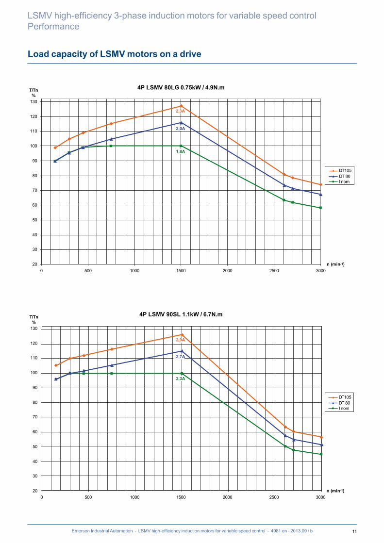
LSMV + BK BRAKE CHARACTERISTICS
2 poles - 3000 min-1
230 or 400 V AC/205 V DC BRAKE POWER SUPPLY
Motor type
Brake type
Rated power
Max. mechanical
speed
Rated torque
Braking torque
Brake consumption
Pick-up time
Brake engage time on DC break
Moment of inertia Weight
PN NS MN MF IF t1 t2 J IM B3
kW min-1 N.m N.m A ms ms kg.m2 kg
LSMV 80 L BK 8 0.75 10,100 2.5 8 0.13 32 60 0.0009 13LSMV 80 L BK 8 1.1 10,100 3.7 8 0.13 32 60 0.001 14LSMV 90 S BK 16 1.5 10,100 4.9 16 0.15 47 73 0.0017 16LSMV 90 L BK 16 2.2 8,300 7.1 16 0.15 47 73 0.0022 22LSMV 100 L BK 32 3 8,300 10.0 32 0.21 57 111 0.0031 30LSMV 112 MR BK 32 4 8,300 13.4 32 0.21 57 111 0.0037 35LSMV 132 S BK 60 5.5 6,700 17.9 60 0.26 38 213 0.015 45LSMV 132 SU BK 60 7.5 6,700 24.1 60 0.26 38 213 0.016 51LSMV 132 M BK 60 9 6,000 29.2 60 0.26 38 213 0.017 60LSMV 160 MP BK 80 11 5,300 35.9 80 0.31 53 221 0.019 73LSMV 160 MR BK 80 15 5,300 49.2 80 0.31 53 221 0.026 85
4 poles - 1500 min-1
230 or 400 V AC/205 V DC BRAKE POWER SUPPLY
Motor type
Brake type
Rated power
Max. mechanical
speed
Rated torque
Braking torque
Brake consumption
Pick-up time
Brake engage time on DC break
Moment of inertia Weight
PN NS MN MF IF t1 t2 J IM B3
kW min-1 N.m N.m A ms ms kg.m2 kg
LSMV 80 LG BK 8 0.75 10,100 4.9 8 0.13 32 60 0.0027 16LSMV 90 SL BK 16 1.1 8,300 6.7 16 0.15 47 73 0.0044 20.9LSMV 90 LU BK 16 1.5 8,300 9.4 16 0.15 47 73 0.0051 22LSMV 100 LR BK 32 2.2 6,700 14.0 32 0.21 57 111 0.0047 30LSMV 100 LG BK 32 3 6,700 19.8 32 0.21 57 111 0.0011 38LSMV 112 MU BK 32 4 6,700 26.0 32 0.21 57 111 0.015 45LSMV 132 SM BK 60 5.5 6,000 35.8 60 0.26 38 213 0.023 72LSMV 132 M BK 60 7.5 6,000 48.8 60 0.26 38 213 0.028 84LSMV 132 MU BK 80 9 5,300 58.7 80 0.31 53 221 0.030 95LSMV 160 MR BK 80 11 5,300 71.4 80 0.31 53 221 0.035 103
6 poles - 1000 min-1
230 or 400 V AC/205 V DC BRAKE POWER SUPPLY
Motor type
Brake type
Rated power
Max. mechanical
speed
Rated torque
Braking torque
Brake consumption
Pick-up time
Brake engage time on DC break
Moment of inertia Weight
PN NS MN MF IF t1 t2 J IM B3
kW min-1 N.m N.m A ms ms kg.m2 kg
LSMV 90 S BK 16 0.75 8,300 7.6 16 0.15 47 73 0.005 18LSMV 90 L BK 16 1.1 8,300 11.0 16 0.15 47 73 0.005 21LSMV 100 L BK 32 1.5 6,700 14.9 32 0.21 57 111 0.006 27LSMV 112 MG BK 32 2.2 6,700 20.9 32 0.21 57 111 0.01 34LSMV 132 S BK 60 3 6,000 29.1 60 0.26 38 213 0.02 52LSMV 132 M BK 60 4 6,000 39.4 60 0.26 38 213 0.03 62LSMV 132 MU BK 60 5.5 6,000 55 60 0.26 38 213 0.04 77

39Emerson Industrial Automation - LSMV high-efficiency induction motors for variable speed control - 4981 en - 2013.09 / b
Forced ventilation
LSMV high-efficiency 3-phase induction motors for variable speed controlInstallation and motor options
The motors are self-cooled
as standard
To maintain the rated torque over the entire speed range, forced ventilation may be necessary.
Characteristics of forced ventilation units
Motor typeFV
Supply voltage(1)
FV consumption Ingress protection(2)
FVP (W) W
I (A) A
LSMV 80 to 132 single-phase 230 or 400 V 100 0.43/0.25 IP55
LSMV 160 to 280 SDthree-phase
230/400 V 50 Hz 254/460 V 60 Hz 150 0.94/0.55 IP55
LSMV 280 MKLSMV 315 M
three-phase 230/400 V 50 Hz 254/460 V 60 Hz
750 3.6/2.1 IP55
(1) ± 10% for voltage, ± 2% for frequency.(2) Ingress protection of the forced ventilation unit installed on the motor.
BlackW V
CP2
CP1
ZUBlue
Brown
Motor type
Capacitors
CP1 CP2
LSMV 90 to 132
U = 230 V Power supply on U and WU = 400 V Power supply on V and W
3 mf 2 mf
230 or 400 V SINGLE-PHASE FORCED VENTILATIONfor frame size ≤ 132
THREE-PHASE FORCED VENTILATIONfor frame size > 132
1 SPEED - 2 VOLTAGES L1 - L2 - L3
W2 U2 V2
L1 L2 L3
U1 V1 W1
W2 U2 V2
L1 L2 L3
U1 V1 W1

40 Emerson Industrial Automation - LSMV high-efficiency induction motors for variable speed control - 4981 en - 2013.09 / b
LSMV high-efficiency 3-phase induction motors for variable speed controlInstallation and motor options
Thermal protection
The motors are protected by the variable speed drive, placed between the isolating switch and the motor.The variable speed drive provides total protection of the motor against overloads.
The motors are fitted with PTC sensors in the winding. As an option, specific thermal protection sensors can be selected from the table below.
It must be emphasized that under no circumstances can these sensors be used to carry out direct regulation of the motor operating cycles.
Fitting thermal protection- PTO or PTF, in the control circuits- PTC, with relay, in the control circuits- PT 100 or thermocouples, with reading equipment or recorder, in the installation control panel for continuous surveillance
Alarm and early warningAll protective equipment can be backed up by another type of protection (with different NRTs): the first device will then act as an early warning (light or sound signals given without shutting down the power circuits), and the second device will be the alarm (shutting down the power circuits).
Built-in indirect thermal protection
Type Operating principle Operating curve Breaking capacity (A) Protection provided Mounting
Number of devices*
Normally closed thermal protection
PTO
Bimetallic strip, indirectly heated, with normally closed (NC) contact
I
O TNFT
2.5 A at 250 Vwith cos j 0.4
General monitoringfor non-transient overloads
Mounting in control circuit
2 or 3 in series
Normally open thermal protection
PTF
Bimetallic strip, indirectly heated, with normally open
(NO) contact
I
F TNFT
2.5 A at 250 Vwith cos j 0.4
General monitoringfor non-transient overloads
Mounting in control circuit
2 or 3 in parallel
Positive temperature coefficient thermistor
PTC
Variable non-linear resistor with indirect heating
R
TNFT
0 General monitoringfor transient overloads
Mounted with associated relay in control circuit
3 in series
Temperature sensorKT U
Resistance depends on the winding temperature
R
T
0 High accuracy continuous surveillance of key hot spots
Mounted in control boards with associated reading equipment
(or recorder)
1 per hot spot
ThermocouplesT (T < 150°C)
Copper ConstantanK (T < 1000°C)Copper-nickel
Peltier effect
V
T
0 Continuous surveillance of hot spots at regular intervals
Mounted in control boards with associated reading equipment
(or recorder)
1 per hot spot
Platinum resistance thermometer
PT 100Variable linear resistor with
indirect heating
R
T
0 High accuracy continuous surveillance of key hot spots
Mounted in control boards with associated reading equipment
(or recorder)
1 per hot spot
- NRT: nominal running temperature.- The NRTs are chosen according to the position of the sensor in the motor and the temperature rise class.- standard kTy = 84/130
* The number of devices relates to the winding protection.
The motors are fitted with
PTC sensors as standard

41Emerson Industrial Automation - LSMV high-efficiency induction motors for variable speed control - 4981 en - 2013.09 / b
Mains connection
LSMV high-efficiency 3-phase induction motors for variable speed controlInstallation and motor options
CABLE GLANDSIn certain applications, it is necessary for there to be earth continuity between the cable and the motor earth to ensure the installation is protected in accordance
with EMC directive 89/336/EEC. An optional cable gland with anchorage on shielded cable is therefore available over the entire range.
Number and type of cable gland
Series Type Number of polesTerminal box material
Power + auxiliaries
Number of drill holes Drill hole diameter
LSMV
80 L/LG 2; 4; 6
Aluminium alloy
2 1 x M20 + 1 x M1690 S/SL/L 2; 4; 6100 L/LR/LG 2; 4; 6112 MR/MG/MU 2; 4; 6132 S/SM/M/MU 2; 4; 6
2 1 x M25 + 1 x M16160 MP/MR 2; 4; 6160 L/LUR 2; 4
3
2 x M25 + 1 x M16180 MT/M/LUR 2; 4
2 x M40 + 1 x M16200 LR/L 2; 4225 SR/MT/MG 2; 4 2 x M50 + 1 x M16250 ME 4
2 x M63 + 1 x M16280 SD/MK 4
315 SP/MR 4 0 Removable undrilled mounting plate
The motors are supplied with pre-drilled
and tapped terminal boxes or an undrilled
mounting plate for mounting cable glands

42
E
D
M.O x p
EA
DA
L' LO'
MOA x pA
F
GD G
FA
GF GB
LLO
Emerson Industrial Automation - LSMV high-efficiency induction motors for variable speed control - 4981 en - 2013.09 / b
LSMV high-efficiency 3-phase induction motors for variable speed controlDimensions
Shaft extensions
Dimensions in millimetres
Type
Main shaft extensions4 and 6 poles 2 poles
F GD D G E O p L LO F GD D G E O p L LOLSMV 80 L/LG 6 6 19j6 15.5 40 6 16 30 6 6 6 19j6 15.5 40 6 16 30 6LSMV 90 S/SL/L/LU 8 7 24j6 20 50 8 19 40 6 8 7 24j6 20 50 8 19 40 6LSMV 100 L/LR/LG 8 7 28j6 24 60 10 22 50 6 8 7 28j6 24 60 10 22 50 6LSMV 112 MR/MG/MU 8 7 28j6 24 60 10 22 50 6 8 7 28j6 24 60 10 22 50 6LSMV 132 S/SU/SM/M/MU 10 8 38k6 33 80 12 28 63 10 10 8 38k6 33 80 12 28 63 10LSMV 160 MP/MR/LUR 12 8 42k6 37 110 16 36 100 6 12 8 42k6 37 110 16 36 100 6LSMV 180 M/LUR 14 9 48k6 42.5 110 16 36 98 12 14 9 48k6 42.5 110 16 36 98 12LSMV 200 L 16 10 55m6 49 110 20 42 97 13 16 10 55m6 49 110 20 42 97 13LSMV 225 SR/MR 18 11 60m6 53 140 20 42 126 14 16 10 55m6 49 110 20 42 97 13LSMV 250 ME 18 11 65m6 58 140 20 42 126 14LSMV 280 SD/MK 20 12 75m6 67.5 140 20 42 125 15LSMV 315 SP/MR 22 14 80m6 71 170 20 42 155 15
Type
Secondary shaft extensions4 and 6 poles 2 poles
FA GF DA GB EA OA pA L' LO' FA GF DA GB EA OA pA L' LO'LSMV 80 L/LG 5 5 14j6 11 30 5 15 25 3.5 5 5 14j6 11 30 5 15 25 3.5LSMV 90 S/SL/L/LU 6 6 19j6 15.5 40 6 16 30 6 6 6 19j6 15.5 40 6 16 30 6LSMV 100 L/LR/LG 8 7 24j6 20 50 8 19 40 6 8 7 24j6 20 50 8 19 40 6LSMV 112 MR/MG/MU 8 7 24j6 20 50 8 19 40 6 8 7 24j6 20 50 8 19 40 6LSMV 132 S/SU/SM/M/MU 8 7 28k6 24 60 10 22 50 6 8 7 28k6 24 60 10 22 50 6LSMV 160 MP/MR 12 8 38k6 37 80 16 36 100 6 12 8 38k6 37 80 16 36 100 6LSMV 160 LUR 12 8 42k6 37 110 16 36 100 6 12 8 42k6 37 110 16 36 100 6LSMV 180 M/L/LU 14 9 48k6 42.5 110 16 36 98 12 14 9 48k6 42.5 110 16 36 98 12LSMV 200 LT/L 16 10 55m6 49 110 20 42 97 13 16 10 55m6 49 110 20 42 97 13LSMV 225 SR/MR/MG 18 11 60m6 53 140 20 42 126 14 16 10 55m6 49 110 20 42 97 13LSMV 250 ME 18 11 60m6 53 140 20 42 126 14 18 11 60m6 53 140 20 42 126 14LSMV 280 SD/SC/MC/MK 18 11 65m6 58 140 20 42 126 14LSMV 315 SP/MP/MR 22 14 80m6 71 170 24 42 155 15

43
J LJ
LB
Ø AC
x
B C
BB
A
HD
H HA
AB
AA4 Ø K
I II
ADAD1
Emerson Industrial Automation - LSMV high-efficiency induction motors for variable speed control - 4981 en - 2013.09 / b
Foot mounted IM 1001 (IM B3)
LSMV high-efficiency 3-phase induction motors for variable speed controlDimensions
Dimensions in millimetres
TypeMain dimensions
A AB B BB C x AA K HA H AC* HD LB LJ J I II AD AD1LSMV 80 L 125 157 100 120 50 10 29 9 10 80 170 221 212 13.5 160 55 55 - -LSMV 80 LG 125 157 100 125 50 14 31 9 10 80 185 231 243 13.5 160 55 55 - -LSMV 90 S 140 172 100 120 56 10 37 10 11 90 190 241 212 13.5 160 55 55 - -LSMV 90 SL 140 172 100 162 56 28 39 10 11 90 190 241 239 13.5 160 55 55 - -LSMV 90 L 140 172 125 162 56 28 39 10 11 90 190 241 239 13.5 160 55 55 - -LSMV 90 LU 140 172 125 162 56 28 39 10 11 90 190 241 265 13.5 160 55 55 - -LSMV 100 L 160 196 140 165 63 12 40 12 13 100 200 256 288 14.5 160 55 55 118 45LSMV 100 LR 160 196 140 165 63 12 40 12 13 100 200 256 314 14.5 160 55 55 118 45LSMV 100 LG 160 196 140 170 63 11 49 12 13 100 230 265 305 23.5 160 55 55 - -LSMV 112 MR 190 220 140 165 70 13 45 12 14 112 200 268 314 14.5 160 55 55 - -LSMV 112 MG 190 220 140 165 70 12 52 12 14 112 235 277 305 23.5 160 55 55 118 45LSMV 112 MU 190 220 140 165 70 12 52 12 14 112 235 277 333 23.5 160 55 55 - -LSMV 132 S 216 250 140 170 89 16 42 12 16 132 220 300 350 40.5 160 55 55 130 45LSMV 132 SU 216 250 140 170 89 16 42 12 16 132 220 300 377 40.5 160 55 55 130 45LSMV 132 SM 216 250 140 208 89 15 50 12 15 132 265 318 410 50 160 55 55 140 45LSMV 132 M 216 250 178 208 89 15 50 12 15 132 265 318 385 25 160 55 55 140 45LSMV 132 MU 216 250 178 208 89 15 50 12 15 132 265 318 412 25 160 55 55 140 45LSMV 160 MP 254 294 210 294 108 20 64 14 25 160 264 346 468 66.5 160 55 55 155 45LSMV 160 MR 254 294 210 294 108 20 64 14 25 160 264 346 495 66.5 160 55 55 155 45LSMV 160 LUR 254 294 254 294 108 20 60 14.5 25 160 312 395 510 42.75 135 88 64 - -LSMV 180 M 279 339 241 329 121 25 86 14.5 25 180 350 456 546 94.5 186 112 98 - -LSMV 180 LUR 279 339 279 329 121 25 86 14.5 25 180 350 436 614 63.5 186 112 98 - -LSMV 200 L 318 388 305 375 133 35 103 18.5 36 200 390 476 621 77 186 112 98 - -LSMV 225 SR 356 431 286 386 149 50 127 18.5 36 225 390 535 675.5 61 231 119 142 - -LSMV 225 MG 356 420 311 375 149 30 65 18.5 30 225 479 631 803.5 61 292 151 181 - -LSMV 250 ME 406 470 349 420 168 35 90 24 36 250 479 656 810 67.5 292 151 181 - -LSMV 280 SD 457 520 368 478 190 35 90 24 35 280 479 686 870 67.5 292 151 181 - -LSMV 280 MK 457 533 419 495 190 40 85 24 35 280 586 765 921 98.5 292 151 181 - -LSMV 315 SP 508 594 406 537 216 40 114 28 70 315 586 867 947 61.5 418 180 235 - -LSMV 315 MR 508 594 457 537 216 40 114 28 70 315 586 867 1017 61.5 418 180 235 - -
* AC: housing diameter without lifting rings

44
A
HD
H
I II
HA
AB
AA
M
n Ø S
4 Ø K
LA
J LJ
LB
T
x
B C
N Pj6
Ø AC
BB
α =
45°
Emerson Industrial Automation - LSMV high-efficiency induction motors for variable speed control - 4981 en - 2013.09 / b
LSMV high-efficiency 3-phase induction motors for variable speed controlDimensions
Foot and flange mounted IM 2001 (IM B35)
Dimensions in millimetres
TypeMain dimensions
A AB B BB C x AA K HA H AC* HD LB LJ J I II SymbolLSMV 80 L 125 157 100 120 50 10 29 9 10 80 170 221 212 14.5 160 55 55 FF 165LSMV 80 LG 125 157 100 125 70 14 31 9 10 80 185 237 262 34.5 160 55 55 FF 165LSMV 90 S 140 172 100 120 76 10 37 10 11 90 190 241 232 33.5 160 55 55 FF 165LSMV 90 SL 140 172 125 162 76 28 39 10 11 90 190 241 259 33.5 160 55 55 FF 165LSMV 90 L 140 172 125 162 76 28 39 10 11 90 190 241 259 33.5 160 55 55 FF 165LSMV 90 LU 140 172 125 162 76 28 39 10 11 90 190 241 285 33.5 160 55 55 FF 165LSMV 100 L 160 196 140 165 63 12 40 12 13 100 200 256 288 14.5 160 55 55 FF 215LSMV 100 LR 160 196 140 165 63 12 40 12 13 100 200 262 307 14.5 160 55 55 FF 215LSMV 100 LG 160 196 140 170 63 11 49 12 13 100 230 265 305 13.5 160 55 55 FF 215LSMV 112 MR 190 220 140 165 70 13 45 12 14 112 200 268 314 14.5 160 55 55 FF 215LSMV 112 MG 190 220 140 165 69 12 52 12 14 112 235 277 305 23.5 160 55 55 FF 215LSMV 112 MU 190 220 140 165 70 12 52 12 14 112 235 277 333 23.5 160 55 55 FF 215LSMV 132 S 216 250 140 170 89 16 42 12 16 132 220 300 350 40.5 160 55 55 FF 265LSMV 132 SU 216 250 140 170 89 16 42 12 16 132 220 300 377 40.5 160 55 55 FF 265LSMV 132 SM 216 250 178 208 89 15 50 12 15 132 265 318 410 50 160 55 55 FF 265LSMV 132 M 216 250 178 208 89 15 50 12 15 132 265 318 385 25 160 55 55 FF 265LSMV 132 MU 216 250 178 208 89 15 50 12 15 132 265 318 412 25 160 55 55 FF 265LSMV 160 MP 254 294 210 294 108 20 64 14 25 160 264 346 468 66.5 160 55 55 FF 300LSMV 160 MR 254 294 210 294 108 20 64 14 25 160 264 346 495 66.5 160 55 55 FF 300LSMV 160 LUR 254 294 254 294 108 20 60 14.5 25 160 312 395 510 42.75 135 88 64 FF 300LSMV 180 M 279 339 241 329 121 25 86 14.5 25 180 350 456 546 94.5 186 112 98 FF 300LSMV 180 LUR 279 339 279 329 121 25 86 14.5 25 180 350 436 614 63.5 186 112 98 FF 300LSMV 200 L 318 388 305 375 133 35 103 18.5 36 200 390 476 621 77 186 112 98 FF 350LSMV 225 SR 356 431 286 386 149 50 127 18.5 36 225 390 535 675.5 61 231 119 142 FF 400LSMV 225 MG 356 420 311 375 149 30 65 18.5 30 225 479 631 803.5 61 292 151 181 FF 400LSMV 250 ME 406 470 349 420 168 35 90 24 36 250 479 656 810 67.5 292 151 181 FF 500LSMV 280 SD 457 520 368 478 168 35 90 24 35 280 479 686 870 67.5 292 151 181 FF 500LSMV 280 MK 457 533 419 495 190 40 85 24 35 280 586 765 921 98.5 292 151 181 FF 500LSMV 315 SP 508 594 406 537 216 40 114 28 70 315 586 867 947 61.5 418 180 235 FF 600LSMV 315 MR 508 594 457 537 216 40 114 28 70 315 586 867 1017 61.5 418 180 235 FF 600
* AC: housing diameter without lifting rings

45
HJ
I II
n Ø S LA
J LJ
T
N Pj6
Ø AC
α
LB
M
Emerson Industrial Automation - LSMV high-efficiency induction motors for variable speed control - 4981 en - 2013.09 / b
Flange mounted IM 3001 (IM B5) IM 3011 (IM V1)
LSMV high-efficiency 3-phase induction motors for variable speed controlDimensions
Dimensions in millimetres
IEC symbol
Flange dimensionsType
Main dimensionsM N P T n α° S LA AC* LB HJ LJ J I II
FF 165 165 130 200 3.5 4 45 12 10 LSMV 80 L 170 212 141 14.5 160 55 55FF 165 165 130 200 3.5 4 45 12 10 LSMV 80 LG 185 263 151 34.5 160 55 55FF 165 165 130 200 3.5 4 45 12 10 LSMV 90 S 190 232 151 33.5 160 55 55FF 165 165 130 200 3.5 4 45 12 10 LSMV 90 SL 190 259 151 33.5 160 55 55FF 165 165 130 200 3.5 4 45 12 10 LSMV 90 L 190 259 151 33.5 160 55 55FF 165 165 130 200 3.5 4 45 12 10 LSMV 90 LU 190 285 151 33.5 160 55 55FF 215 215 180 250 4 4 45 14.5 12 LSMV 100 L 200 288 156 14.5 160 55 55FF 215 215 180 250 4 4 45 14.5 12 LSMV 100 LR 200 314 156 14.5 160 55 55FF 215 215 180 250 4 4 45 14.5 12 LSMV 100 LG 230 305 165 13.5 160 55 55FF 215 215 180 250 4 4 45 14.5 11 LSMV 112 MR 200 314 156 14.5 160 55 55FF 215 215 180 250 4 4 45 14.5 11 LSMV 112 MG 235 305 165 23.5 160 55 55FF 215 215 180 250 4 4 45 14.5 11 LSMV 112 MU 235 333 165 23.5 160 55 55FF 265 265 230 300 4 4 45 14.5 12 LSMV 132 S 220 350 168 40.5 160 55 55FF 265 265 230 300 4 4 45 14.5 12 LSMV 132 SU 220 377 168 40.5 160 55 55FF 265 265 230 300 4 4 45 14.5 12 LSMV 132 SM 265 410 186 50 160 55 55FF 265 265 230 300 4 4 45 14.5 12 LSMV 132 M 265 385 186 25 160 55 55FF 265 265 230 300 4 4 45 14.5 12 LSMV 132 MU 265 412 186 25 160 55 55FF 300 300 250 350 5 4 45 18.5 14 LSMV 160 MP 264 468 186 66.5 160 55 55FF 300 300 250 350 5 4 45 18.5 14 LSMV 160 MR 264 495 186 66.5 160 55 55FF 300 300 250 350 5 4 45 18.5 14 LSMV 160 LUR 312 510 235 42.75 135 88 64FF 300 300 250 350 5 4 45 18.5 14 LSMV 180 M 350 546 276 94.5 186 112 98FF 300 300 250 350 5 4 45 18.5 14 LSMV 180 LUR 350 614 256 63.5 186 112 98FF 350 350 300 400 5 4 45 18.5 15 LSMV 200 L 390 621 276 77 186 112 98FF 400 400 350 450 5 8 22.5 18.5 16 LSMV 225 SR 390 675.5 310 61 231 119 142FF 400 400 350 450 5 8 22.5 18.5 16 LSMV 225 MG 479 803.5 406 61 292 151 181FF 500 500 450 550 5 8 22.5 18.5 18 LSMV 250 ME 479 810 406 67.5 292 151 181FF 500 500 450 550 5 8 22.5 18.5 18 LSMV 280 SD 479 870 406 67.5 292 151 181FF 500 500 450 550 5 8 22.5 18.5 18 LSMV 280 MK 586 921 466 98.5 292 151 181FF 600 600 550 660 6 8 22.5 24 22 LSMV 315 SP 586 947 555 61.5 418 180 235FF 600 600 550 660 6 8 22.5 24 22 LSMV 315 MR 586 1017 555 61.5 418 180 235
* AC: housing diameter without lifting rings
FF flange mounted motors in position IM 3001 are only available up to frame size 225.Dimensions of shaft extensions identical to those for foot mounted motors.

46
A
HD
H HA
AB
AA4 Ø K
I
M
n x MSII
J LJ
LB
T
N Pj6
Ø AC
x
B C
BB
α =
45°
Emerson Industrial Automation - LSMV high-efficiency induction motors for variable speed control - 4981 en - 2013.09 / b
LSMV high-efficiency 3-phase induction motors for variable speed controlDimensions
Foot and face mounted IM 2101 (IM B34)
Dimensions in millimetres
TypeMain dimensions
A AB B BB C x AA K HA H AC* HD LB LJ J I II SymbolLSMV 80 L 125 157 100 120 50 10 29 9 10 80 170 221 212 13.5 160 55 55 FT 100LSMV 80 LG 125 157 100 125 50 14 31 9 10 80 185 231 243 13.5 160 55 55 FT 100LSMV 90 S 140 172 100 120 56 10 37 10 11 90 190 241 212 13.5 160 55 55 FT 115LSMV 90 SL 140 172 125 162 56 28 39 10 11 90 190 241 239 13.5 160 55 55 FT 115LSMV 90 L 140 172 125 162 56 28 39 10 11 90 190 241 239 13.5 160 55 55 FT 115LSMV 90 LU 140 172 125 162 56 28 39 10 11 90 190 241 265 13.5 160 55 55 FT 115LSMV 100 L 160 196 140 165 63 12 40 12 13 100 200 256 288 14.5 160 55 55 FT 130LSMV 100 LR 160 196 140 165 63 12 40 12 13 100 200 256 314 14.5 160 55 55 FT 130LSMV 100 LG 160 196 140 170 63 11 49 12 13 100 230 265 305 23.5 160 55 55 FT 130LSMV 112 MR 190 220 140 165 70 13 45 12 14 112 200 268 314 14.5 160 55 55 FT 130LSMV 112 MG 190 220 140 165 70 12 52 12 14 112 235 277 305 23.5 160 55 55 FT 130LSMV 112 MU 190 220 140 165 70 12 52 12 14 112 235 277 333 23.5 160 55 55 FT 130LSMV 132 S 216 250 140 170 89 16 42 12 16 132 220 300 350 40.5 160 55 55 FT 215LSMV 132 SU 216 250 140 170 89 16 42 12 16 132 220 300 377 40.5 160 55 55 FT 215LSMV 132 SM 216 250 178 208 89 15 50 12 15 132 265 318 410 50 160 55 55 FT 215LSMV 132 M 216 250 178 208 89 15 50 12 15 132 265 318 385 25 160 55 55 FT 215LSMV 132 MU 216 250 178 208 89 15 50 12 15 132 265 318 412 25 160 55 55 FT 215LSMV 160 MP 254 294 210 294 108 20 64 14 25 160 264 346 468 66.5 160 55 55 FT 265LSMV 160 MR 254 294 210 294 108 20 64 14 25 160 264 346 495 66.5 160 55 55 FT 265
* AC: housing diameter without lifting rings

47
J LJ
T
N Pj6
Ø AC
HJ
I
AC
n x MSII
α =
45°
LB
M
Emerson Industrial Automation - LSMV high-efficiency induction motors for variable speed control - 4981 en - 2013.09 / b
Face mounted IM 3601 (IM B14)
LSMV high-efficiency 3-phase induction motors for variable speed controlDimensions
Dimensions in millimetres
IEC symbolFaceplate dimensions
TypeMain dimensions
M N P T n MS AC* LB HJ LJ J I IIFT 100 100 80 120 3 4 M6 LSMV 80 L 170 212 141 13.5 160 55 55FT 100 100 80 120 3 4 M6 LSMV 80 LG 185 243 151 13.5 160 55 55FT 115 115 95 140 3 4 M8 LSMV 90 S 190 212 151 13.5 160 55 55FT 115 115 95 140 3 4 M8 LSMV 90 SL 190 239 151 13.5 160 55 55FT 115 115 95 140 3 4 M8 LSMV 90 L 190 239 151 13.5 160 55 55FT 115 115 95 140 3 4 M8 LSMV 90 LU 190 265 151 13.5 160 55 55FT 130 130 110 160 3.5 4 M8 LSMV 100 L 200 288 156 14.5 160 55 55FT 130 130 110 160 3.5 4 M8 LSMV 100 LR 200 314 156 14.5 160 55 55FT 130 130 110 160 3.5 4 M8 LSMV 100 LG 230 305 165 23.5 160 55 55FT 130 130 110 160 3.5 4 M8 LSMV 112 MR 200 314 156 14.5 160 55 55FT 130 130 110 160 3.5 4 M8 LSMV 112 MG 235 305 165 23.5 160 55 55FT 130 130 110 160 3.5 4 M8 LSMV 112 MU 235 333 165 23.5 160 55 55FT 215 215 180 250 4 4 M12 LSMV 132 S 220 350 168 40.5 160 55 55FT 215 215 180 250 4 4 M12 LSMV 132 SU 220 377 168 40.5 160 55 55FT 215 215 180 250 4 4 M12 LSMV 132 SM 265 410 186 50 160 55 55FT 215 215 180 250 4 4 M12 LSMV 132 M 265 385 186 25 160 55 55FT 215 215 180 250 4 4 M12 LSMV 132 MU 265 412 186 25 160 55 55FT 215 215 180 250 4 4 M12 LSMV 160 MP 264 468 186 66.5 160 55 55FT 215 215 180 250 4 4 M12 LSMV 160 MR 264 495 186 66.5 160 55 55
* AC: housing diameter without lifting rings

48 Emerson Industrial Automation - LSMV high-efficiency induction motors for variable speed control - 4981 en - 2013.09 / b
LSMV high-efficiency 3-phase induction motors for variable speed controlDimensions
Dimensions of optional features
LSMV MOTORS WITH OPTIONAL FEATURESThe integration of LSMV motors within a process often requires accessories to make operation easier:- Forced ventilation for motors used at high or low speeds.
- Holding brakes for maintaining the rotor in the stop position without needing to leave the motor switched on.- Emergency stop brakes to immobilise loads in case of failure of the motor torque control or loss of power supply.
- Encoders which provide digital information for accurate speed maintenance and position control.These options can be used singly or in combination as shown in the table below.
LB2 or LB2’LB1 or LB1’
Forced ventilation unit BK holding brake Encoder
Forced ventilation unit and encoder Encoder and BK holding brake Forced ventilation unit with encoder and BK holding brake
LB3 or LB3’
LB4 or LB4’ LB6 or LB6’LB5 or LB5’

49Emerson Industrial Automation - LSMV high-efficiency induction motors for variable speed control - 4981 en - 2013.09 / b
Dimensions of optional features
LSMV high-efficiency 3-phase induction motors for variable speed controlDimensions
Dimensions in millimetres
FOOT OR (FT) FACE MOUNTED MOTORS
TypeMain dimensions
LB1 LB2 LB3 LB4 LB5 LB6LSMV 80 L 317 254 296 352 362 419LSMV 80 LG 322 304 330 385 389 446LSMV 90 S 304 279 302 357 352 389LSMV 90 SL 331 304 329 384 379 416LSMV 90 L 331 304 329 384 379 416LSMV 90 LU 342 326 352 402 379 416LSMV 100 L 373 358 376 430 444 499LSMV 100 LR 381 365 386 431 443 488LSMV 100 LG 411 405 394 455 479 518LSMV 112 MR 407 380 391 438 459 497LSMV 112 MG 412 385 396 443 464 502LSMV 112 MU 426 402 419 466 464 502LSMV 132 S 453 426 437 484 505 543LSMV 132 SU 453 426 437 484 505 543LSMV 132 SM 458 487 454 499 540 578LSMV 132 M 458 487 454 499 540 578LSMV 132 MU 458 511 494 499 540 578LSMV 160 MP 709 527 555 709 615 653LSMV 160 MR 704 580 576 709 615 653LSMV 160 LUR 702 - 574 702 - -LSMV 180 M 735 - 596 735 - -LSMV 180 LUR 769 - 629 769 - -LSMV 200 L 802 - 674 802 - -LSMV 225 SR 854 - 730 854 - -LSMV 225 MG 1006 - 854 1006 - -LSMV 250 ME 1012 - 860 1012 - -LSMV 280 SD 1072 - 920 1072 - -LSMV 280 MK 1111 - 965 1111 - -LSMV 315 SP 1181 - 991 1181 - -LSMV 315 MR 1251 - 1061 1251 - -
(FF) FLANGE OR FOOT AND (FF) FLANGE MOUNTED MOTORS
TypeMain dimensions
LB1’ LB2’ LB3’ LB4’ LB5’ LB6’LSMV 80 L 317 254 296 352 362 419LSMV 80 LG 342 324 350 405 409 466LSMV 90 S 324 299 322 377 372 409LSMV 90 SL 351 324 349 404 399 436LSMV 90 L 351 324 349 404 399 436LSMV 90 LU 362 346 372 422 399 436LSMV 100 L 373 358 376 430 444 499LSMV 100 LR 381 365 386 431 443 488LSMV 100 LG 401 395 384 445 469 508LSMV 112 MR 407 380 391 438 459 497LSMV 112 MG 412 385 396 443 464 502LSMV 112 MU 426 402 419 466 464 502LSMV 132 S 453 426 437 484 505 543LSMV 132 SU 453 426 437 484 505 543LSMV 132 SM 458 487 454 499 540 578LSMV 132 M 458 487 454 499 540 578LSMV 132 MU 458 511 494 499 540 578LSMV 160 MP 709 527 555 709 615 653LSMV 160 MR 704 580 576 709 615 653LSMV 160 LUR 702 - 574 702 - -LSMV 180 M 735 - 596 735 - -LSMV 180 LUR 769 - 629 769 - -LSMV 200 L 802 - 674 802 - -LSMV 225 SR 854 - 730 854 - -LSMV 225 MG 1006 - 854 1006 - -LSMV 250 ME 1012 - 860 1012 - -LSMV 280 SD 1072 - 920 1072 - -LSMV 280 MK 1111 - 965 1111 - -LSMV 315 SP 1181 - 991 1181 - -LSMV 315 MR 1251 - 1061 1251 - -

50 Emerson Industrial Automation - LSMV high-efficiency induction motors for variable speed control - 4981 en - 2013.09 / b
LSMV high-efficiency 3-phase induction motors for variable speed controlConstruction
External finish
Emerson Industrial Automation motors are protected with a range of surface finishes.The surfaces receive appropriate special treatments, as shown below.
Preparation of surfaces
SURFACE PARTS TREATMENT
Cast iron End shields Shot blasting + Primer
SteelAccessories Phosphatization + Primer
Terminal boxes - Fan covers Electrostatic painting or Epoxy powder
Aluminium alloy Housings - Terminal boxes Shot blasting
DEFINITION OF ATMOSPHERESAn atmosphere is said to be harsh when components are attacked by bases, acids or salts. It is said to be corrosive when components are attacked by oxygen.
Paint systems
ATMOSPHERE SYSTEM APPLICATIONS CORROSIVITY CATEGORY * ACC. TO ISO 12944-2
Non-harsh and not very harsh(indoors, rural, industrial)
IaLSMV standard 1 polyurethane top coat, 20/30 μm C3L
Moderately corrosive: humid, and outdoors (temperate climate) IIa 1 Epoxy base coat, 30/40 μm
1 polyurethane top coat, 20/30 μm C3M
Corrosive: maritime, very humid (tropical climate) IIIa1 Epoxy base coat, 30/40 μm
1 Epoxy intermediate coat, 30/40 μm1 polyurethane top coat, 20/30 μm
C4M
Substantial chemical attack: frequent contact with bases, acids, alkalis
Surroundings - neutral environment(not in contact with chlorinated or sulphurous
products)
IIIb**1 Epoxy base coat, 30/40 μm
1 Epoxy intermediate coat, 30/40 μm1 Epoxy top coat, 25/35 μm
C4H
Special conditions. Very harsh, polluted with chlorinated or sulphurous products
Ve**1 Epoxy base coat, 20/30 μm
2 Epoxy intermediate coats, each 35/40 μm1 polyurethane top coat, 35/40 μm
C5I-M
161b**1 base coat, 50 μm
2 Epoxy intermediate coats, 80 μm1 Epoxy top coat, 50 μm
C5M-M
System Ia is for moderate climates and System IIa is for general climates as defined in standard IEC 60721.2.1.
* Values given for information only since the surfaces vary in nature whereas the standard only takes account of steel surfaces.* * Evaluation of the degree of rusting in accordance with ISO 4628 (rusted area between 1 and 0.5%)
Emerson Industrial Automation standard paint colour reference:
RAL 9005

51Emerson Industrial Automation - LSMV high-efficiency induction motors for variable speed control - 4981 en - 2013.09 / b
Definition of “Index of Protection” (IP/IK)
LSMV high-efficiency 3-phase induction motors for variable speed controlConstruction
Ingress protection of electrical equipment enclosuresIn accordance with IEC 60034-5 - EN 60034-5 (IP) - IEC 62262 (IK)
IP
0
1
2
3
4
5
Tests Definition IP Tests Definition IK Tests Definition
1st number:Protection against solid objects
3rd number:Mechanical protection
Ø 50 mm
Ø 12 mm
No protection
Protected against solid objects of over 12 mm (example: a finger)
Protected against solid objects of over 50 mm (example: accidental contact with the hand)
Protected against solid objects of over 2.5 mm (examples: tools, wires)
Ø 2.5 mm
Protected against solid objects of over 1 mm (examples: thin tools, small wires)
Ø 1 mm
2nd number:Protection against liquids
0 No protection 00 No protection
1
15°
2
3
4
60°
5
6
7
8 ..m
0.15
m
1 m
Protected against dust (no deposits of harmful material)
Protected against any dust penetration
Protected against prolonged effects of immersion under pressure
Protected against the effects of immersion between 0.15 and 1 m
Protected against projected water comparable to big waves
Projected against jets of water from all directions from a hose
Protected against projected water from all directions
Protected against rain falling at up to 60° from the vertical
Protected against water drops falling at up to 15° from the vertical
Protected against water drops falling vertically (condensation)
01 Impact energy:0.15 J
02 Impact energy:0.20 J
03 Impact energy:0.37 J
05 Impact energy:0.70 J
07 Impact energy:2 J
09 Impact energy:10 J
150 g
10 cm
250 g
15 cm
250 g
20 cm
250 g40 cm
0.5 kg40 cm
2.5 kg
40 cm
. . m
6
200 g
10 cm
350 g
20 cm
04
06
081.25 kg
40 cm
10 Impact energy:20 J
5 kg
40 cm
Impact energy:5 J
Impact energy:1 J
Impact energy:0.50 J
Example:
Example of an IP55 machine
IP : Ingress protection
5. : Machine protected against dust and accidental contact. Test result: no dust enters in harmful quantities, no risk of direct contact with rotating
parts. The test will last for 2 hours. .5 : Machine protected against jets of water from all directions from hoses at 3 m distance
with a flow rate of 12.5 l/min at 0.3 bar. The test will last for 3 minutes. Test result: no damage from water projected onto the machine.
In standard configuration,
the motors are IP 55/IP 23

52 Emerson Industrial Automation - LSMV high-efficiency induction motors for variable speed control - 4981 en - 2013.09 / b
LSMV high-efficiency 3-phase induction motors for variable speed controlConstruction
Mounting arrangements
Mountings and positions (IEC standard 60034-7)
Foot mounted motors
• all frame sizes
IM 1001 (IM B3)- Horizontal shaft- Feet on floor
IM 1071 (IM B8)- Horizontal shaft- Feet on top
IM 1051 (IM B6)- Horizontal shaft- Wall mounted with feet on left when viewed from drive end
IM 1011 (IM V5)- Vertical shaft facing down- Feet on wall
IM 1061 (IM B7)- Horizontal shaft- Wall mounted with feet on right
when viewed from drive end
IM 1031 (IM V6)- Vertical shaft facing up- Feet on wall
(FF) flange mounted motors
• all frame sizes (except IM 3001, which is limited to frame size 225 mm)
IM 3001 (IM B5)- Horizontal shaft
IM 2001 (IM B35)- Horizontal shaft- Feet on floor
IM 3011 (IM V1)- Vertical shaft facing down
IM 2011 (IM V15)- Vertical shaft facing down- Feet on wall
IM 3031 (IM V3)- Vertical shaft facing up
IM 2031 (IM V36)- Vertical shaft facing up- Feet on wall
(FT) face mounted motors
• all frame sizes ≤ 132 mmIM 3601 (IM B14)- Horizontal shaft
IM 2101 (IM B34)- Horizontal shaft- Feet on floor
IM 3611 (IM V18)- Vertical shaft facing down
IM 2111 (IM V58)- Vertical shaft facing down- Feet on wall
IM 3631 (IM V19)- Vertical shaft facing up
IM 2131 (IM V69)- Vertical shaft facing up- Feet on wall
Motors without drive end shieldCaution: The protection (IP) specified on the IM B9 and IM B15 motor nameplates is provided by the customer when the motor is assembled.
IM 9101 (IM B9)- Threaded
tie rods- Horizontal shaft
IM 1201 (IM B15)- Foot mounted
with threaded tie rods- Horizontal shaft
Frame size (mm)
Mounting positionsIM 1001 IM 1051 IM 1061 IM 1071 IM 1011 IM 1031 IM 3001 IM 3011 IM 3031 IM 2001 IM 2011 IM 2031
≤ 200 l l l l l l l l l l l l
225 and 250 l l l l l l n l l l l l
≥ 280 l n n n n n n l l l l n
l: possible positions.n: please consult Emerson Industrial Automation specifying the coupling method and the axial and radial loads if applicable

53Emerson Industrial Automation - LSMV high-efficiency induction motors for variable speed control - 4981 en - 2013.09 / b
Lubrication
LSMV high-efficiency 3-phase induction motors for variable speed controlConstruction
Series TypeNumber of poles
Types of permanently greased bearing
Grease life L50g according to speed of rotation
3000 rpm 1500 rpm 1000 rpm
N.D.E. D.E. 25°C 40°C 55°C 25°C 40°C 55°C 25°C 40°C 55°C
LSMV
80 L 2 6203 CN 6204 C3 ≥40000 ≥40000 25000 - - - - - -
80 LG 46204 C3 6205 C3
- - -≥40000 ≥40000 31000
- - -
90 S/SL/L 2; 4; 6 ≥40000 ≥40000 24000 ≥40000 ≥40000 34000
90 LU 4 6205 C3 6205 C3 - - - ≥40000 ≥40000 30000 - - -
100 L 2; 6 6205 C3 6206 C3
≥40000 ≥40000 22000 - - - ≥40000 ≥40000 33000
100 LR/LG 4 - - - ≥40000 ≥40000 30000 - - -
112 MR 26205 C3 6206 C3
≥40000 ≥40000 22000 - - - - - -
112 MG 6 - - - - - - ≥40000 ≥40000 33000
112 MU 4 6206 C3 6206 C3 - - - ≥40000 ≥40000 30000 - - -
132 S 2; 6 ≥40000 ≥40000 19000 - - -
≥40000 ≥40000 30000
132 SU 2 - - -
132 SM/M 2; 4; 6 6207 C3 6308 C3 ≥40000 ≥40000 19000 ≥40000 ≥40000 25000 ≥40000 ≥40000 30000
132 MU 4; 6 6307 C3 6308 C3 - - - ≥40000 ≥40000 25000 ≥40000 ≥40000 30000
160 MP 2 6208 C3 6309 C3 ≥40000 35000 18000 - - - - - -
160 MR/LR 2; 4 6308 C3 6309 C3 ≥40000 35000 15000 ≥40000 ≥40000 24000 - - -
160 L 2 6210 C3 6309 C3 ≥40000 30000 15000 - - - - - -
160 LUR 4 6210 C3 6310 C3 - - - ≥40000 ≥40000 25000 - - -
180 M 4 6212 C3 6310 C3 - - - ≥40000 ≥40000 24000 - - -
180 MT 2 6210 C3 6310 C3 ≥40000 30000 15000 - - - - - -
180 LUR 4 6312 C3 6310 C3 - - - ≥40000 ≥40000 22000 - - -
200 L 2; 4 6214 C3 6312 C3 ≥40000 25000 12500 ≥40000 ≥40000 22000 - - -
225 SR 4 6312 C36313 C3
- - - ≥40000 ≥40000 21000 - - -
225 MT 2 6214 C3 ≥40000 22000 11000 - - - - - -
225 MG 4 6216 C3 6314 C3 - - - 40000 40000 20000 - - -
NB: On request, motors can be fitted with one or two grease nipples depending on the type, except the 132 S/SU.
BEARINGS WITH GREASE NIPPLES
Series TypeNumber of
poles
Types of bearing for bearings with grease
nipplesQuantityof grease
Regreasing intervals in hours
3000 rpm 1500 rpm 1000 rpm
N.D.E. D.E. g 25°C 40°C 55°C 25°C 40°C 55°C 25°C 40°C 55°C
LSMV
250 ME 4 6216 C3 6314 C325
- - - 22000 11000 5500 - - -
280 SD 4 6218 C3 6316 C3 - - - 20000 10000 5000 - - -
280 MK 4 6317 C3 6317 C3 40 - - - 19000 9800 4900 - - -
315 SP 46317 C3 6320 C3 50
- - -15000 7500 3750
- - -
315 MR 4 - - - - - -
PERMANENTLY GREASED BEARINGSUnder normal operating conditions, the service life in hours of the lubricant is indicated in the table below for ambient temperatures less than 55°C.

54 Emerson Industrial Automation - LSMV high-efficiency induction motors for variable speed control - 4981 en - 2013.09 / b
LSMV high-efficiency 3-phase induction motors for variable speed controlConstruction
Axial loads
Horizontal motor
For a bearing life L10h of 25,000 hours and 40,000 hours
Series TypeNumber of
poles
Permissible axial load (in daN) on main shaft extension for standard bearing assembly
IM B3/B6 IM B7/B8
IM B5/B35 IM B14/B34
3000 rpm 1500 rpm 1000 rpm
25,000 hours
40,000 hours
25,000 hours
40,000 hours
25,000 hours
40,000 hours
25,000 hours
40,000 hours
25,000 hours
40,000 hours
25,000 hours
40,000 hours
LSMV
80 L 2 32 23 62 53 - - - - - - - -
80 LG 4 - - - - 47 34 87 74 - - - -
90 S/SL/L 2; 4; 6 29 20 69 59 45 32 85 72 60 44 100 84
90 LU 4 - - - - 42 28 92 78 - - - -
100 L 2; 6 43 30 93 80 - - - - 85 63 135 113
100 LR 4 - - - - 63 45 113 95 - - - -
100 LG 4 - - - - 67 49 117 99 - - - -
112 MR 2 42 29 92 79 - - - - - - - -
112 MG 6 - - - - - - - - 81 60 131 110
112 MU 4 - - - - 56 39 116 98 - - - -
132 S/SU 2; 6 74 54 134 114 - - - - 131 99 191 159
132 SM/M 2; 4; 6 110 82 180 152 157 120 227 190 190 146 260 216
132 MU 4; 6 - - - - 150 113 230 193 180 136 260 216
160 MP 2 149 113 229 193 - - - - - - - -
160 MR/LR 2; 4 144 108 234 198 204 156 294 246 - - - -
160 L 2 126 91 226 191 - - - - - - - -
160 LUR 4 - - - - 230 176 278 224 - - - -
180 M 4 - - - - 243 188 291 236 - - - -
180 MT 2 158 117 258 217 - - - - - - - -
180 LUR 4 - - - - 199 147 262 210 - - - -
200 LR 2 237 184 300 247 - - - - - - - -
200 L 2; 4 249 195 315 261 325 253 391 319 - - - -
225 SR 4 339 261 402 324 - - - -
225 MT 2 279 219 345 285 - - - - - - - -
225 MG 4 - - - - 378 290 448 360 - - - -
250 ME 4 - - - - 392 303 462 373 - - - -
280 SD 4 - - - - 429 246 517 246 - - - -
280 MK 4 - - - - 632 521 452 341 - - - -
315 SP 4 - - - - 792 650 612 470 - - - -
315 MR 4 - - - - 753 613 573 433 - - - -

55Emerson Industrial Automation - LSMV high-efficiency induction motors for variable speed control - 4981 en - 2013.09 / b
Axial loads
LSMV high-efficiency 3-phase induction motors for variable speed controlConstruction
Vertical motorShaft facing down
For a bearing life L10h of 25,000 hours and 40,000 hours
Series TypeNumber of
poles
Permissible axial load (in daN) on main shaft extension for standard bearing assembly
IM V5 IM V1/V15
IM V18/V58
3000 rpm 1500 rpm 1000 rpm
25,000 hours
40,000 hours
25,000 hours
40,000 hours
25,000 hours
40,000 hours
25,000 hours
40,000 hours
25,000 hours
40,000 hours
25,000 hours
40,000 hours
LSMV
80 L 2 30 21 64 55 - - - - - - - -
80 LG 4 - - - - 45 32 92 78 - - - -
90 S/SL/L 2; 4; 6 27 17 74 64 42 29 91 78 56 41 106 90
90 LU 4 - - - - 38 24 85 98 - - - -
100 L 2; 6 40 26 99 86 - - - - 80 58 143 121
100 LR 4 - - - - 57 39 122 104 - - - -
100 LG 4 - - - - 61 42 128 110 - - - -
112 MR 2 38 25 99 86 - - - - - - - -
112 MG 6 - - - - - - - - 75 53 143 121
112 MU 4 - - - - 49 31 129 111 - - - -
132 S/SU 2; 6 67 47 145 125 - - - - 122 90 207 175
132 SM/M 2; 4; 6 101 73 196 168 145 108 247 210 179 134 279 235
132 MU 4; 6 - - - - 136 98 253 215 165 121 286 242
160 MP 2 137 101 249 212 - - - - - - - -
160 MR/LR 2; 4 129 93 257 221 187 138 323 274 - - - -
160 L 2 104 69 262 226 156 109 317 270 - - - -
160 LUR 4 - - - - 204 149 328 274 - - - -
180 M 4 - - - - 210 156 345 290 - - - -
180 MT 2 134 93 196 255 - - - - - - - -
180 LUR 4 - - - - 163 110 334 280 - - - -
200 LR 2 202 148 358 304 - - - - - - - -
200 L 2; 4 211 156 370 316 276 203 472 400 - - - -
225 SR 4 - - - - 284 204 503 426 - - - -
225 MT 2 238 177 408 347 - - - - - - - -
225 MG 4 - - - - 276 186 419 529 - - - -
250 ME 4 - - - - 299 208 626 535 - - - -
280 SD 4 - - - - 310 125 726 453 - - - -
280 MK 4 - - - - 453 340 725 612 - - - -
315 SP 4 - - - - 607 463 892 748 - - - -
315 MR 4 - - - - 521 378 952 808 - - - -

56 Emerson Industrial Automation - LSMV high-efficiency induction motors for variable speed control - 4981 en - 2013.09 / b
LSMV high-efficiency 3-phase induction motors for variable speed controlConstruction
Axial loads
Series TypeNumber of
poles
Permissible axial load (in daN) on main shaft extension for standard bearing assembly
IM V6 IM V3/V36
IM V19/V69
3000 rpm 1500 rpm 1000 rpm
25,000 hours
40,000 hours
25,000 hours
40,000 hours
25,000 hours
40,000 hours
25,000 hours
40,000 hours
25,000 hours
40,000 hours
25,000 hours
40,000 hours
LSMV
80 L 2 60 51 34 25 - - - - - - - -
80LG 4 69 59 35 25 - - - - - - - -
90 S/SL/L 2; 4; 6 67 57 34 24 82 69 51 38 96 81 66 50
90 LU 4 - - - - 87 74 48 35 - - - -
100 L 2; 6 90 76 49 36 - - - - 130 108 93 72
100 LR 4 - - - - 107 89 72 54 - - - -
100 LG 4 - - - - 111 92 78 60 - - - -
112 MR 2 88 75 49 36 - - - - - - - -
112 MG 6 - - - - - - - - 125 103 93 71
112 MU 4 - - - - 109 91 69 51 - - - -
132 S 2; 6 127 107 86 66 - - - - 182 150 147 115
132 SU 2 - - - - 151 90 116 124 - - - -
132 SM/M 2; 4; 6 171 143 126 98 215 178 177 140 249 205 209 165
132 MU 4; 6 - - - - 216 179 173 135 245 201 206 162
160 MP 2 217 181 169 132 - - - - - - - -
160 MR/LR 2; 4 219 183 167 131 277 228 233 184 - - - -
160 L 2 204 169 162 126 - - - - - - - -
160 LUR 4 - - - - 252 197 280 226 - - - -
180 M 4 - - - - 258 204 297 242 - - - -
180 MT 2 234 193 196 155 - - - - - - - -
180 LUR 4 - - - - 248 194 285 231 - - - -
200 LR 2 265 211 295 241 - - - - - - - -
200 L 2; 4 277 222 304 250 342 269 406 334 - - - -
225 SR 4 - - - - 347 267 440 360 - - - -
225 MT 2 304 243 342 281 - - - - - - - -
225 MG 4 - - - - 346 256 549 459 - - - -
250 ME 4 - - - - 369 278 556 465 - - - -
280 SD 4 - - - - 398 125 638 453 - - - -
280 MK 4 - - - - 273 160 905 792 - - - -
315 SP 4 - - - - 427 283 1072 928 - - - -
315 MR 4 - - - - 341 198 1132 988 - - - -
Vertical motorShaft facing up
For a bearing life L10h of 25,000 hours and 40,000 hours

57
LSMV 100 LGLSMV 112 MG / MU
0 10 20 40 5030
LSMV 100 LR / 112 MRLSMV 100 L
30
40
50
60
70
80
90
100
LSMV 90 SFR(daN)
x (mm)
6P / 1000 min -1
2P / 3000 min -1
0 10 20 30 4030
90LSMV 80 L / LGFR
(daN)
x (mm)
70
80
60
50
40
80 LG / 4P / 1500 min -1
80 L / 2P / 3000 min -1
60
120
FR(daN)
x (mm)
100
110
90
80
70
0 10 20 40 503030
40
50
60
70
80
90
100
LSMV 90 SL / L / LUFR(daN)
x (mm)
70
80
90
100
110
120
130
140
90 SL / 4P / 1500 min -1
90 L / 2P / 3000 min -1
90 LU / 4P / 1500 min -1 90 L / 6P / 1000 min -1
110
120
130140
100
90
80
70
60
50100 20 30 40 50 60 100 20 30 40 50 60
FR(daN)
x (mm)
6P / 1000 min -1
2P / 3000 min -1
100 20 30 40 50 60
FR(daN)
x (mm)
100 LR / 4P / 1500 min -1
112 MR / 2P / 3000 min -1100 LG / 4P / 1500 min -1112 MG / 6P / 1000 min -1
112 MU / 4P / 1500 min -1
LSMV 132 M
0 2010 30 50 7040 60 8090
210LSMV 132 S / SUFR
(daN)
x (mm)
170
190
150
130
110
2010 30 50 7040 60 80
132 S / 6P / 1000 min -1
132 S/SU / 2P / 3000 min -1
0150
170
190
210
230
250
270
290
FR(daN)
x (mm)
4P / 1500 min -1
2P / 3000 min -1
6P / 1000 min -1
LSMV 132 MU
2010 30 50 7040 60 800150
170
190
210
230
250
270
290
FR(daN)
x (mm)
4P / 1500 min -16P / 1000 min -1
Emerson Industrial Automation - LSMV high-efficiency induction motors for variable speed control - 4981 en - 2013.09 / b
Radial loads
LSMV high-efficiency 3-phase induction motors for variable speed controlConstruction
STANDARD FITTING ARRANGEMENTPermissible radial load on main shaft extension with a bearing life L10h of 25,000 hours.FR: Radial ForceX: Distance with respect to the shaft shoulder

58
LSMV 280 SD
LSMV 160 MP / LR
290
310
330350
270
250
230
210
190
170200 40 60 80 100
FR(daN)
x (mm)
160 MR / 4P / 1500 min -1
160 MP/MR / 2P / 3000 min -1
0 4020 60 100 14080 120 160300
FR(daN)
x (mm)
700
800
600
500
400350
450
550
650
750
0 4020 60 100 14080 120 160200
FR(daN)
x (mm)
600
700
500
400
300250
350
450
550
650
4P / 1500 min -1
LSMV 200 L LSMV 225 SR / MTLSMV 180 LUR
LSMV 160 L / LURFR(daN) LSMV 180 M / MTFR
(daN)
100
500
x (mm)
200
300
400
200 40 60 80 100 110
LSMV 250 MELSMV 225 MG
160 LUR / 4P / 1500 min -1
160 L / 2P / 3000 min -1
100
500
450 450
350 350
250 250
150 150
x (mm)
200
300
400
20 40 60 80 1000 120
180 M / 4P / 1500 min -1
180 MT / 2P / 3000 min -1
225 SR / 4P / 1500 min -1
225 MT / 2P / 3000 min -1
FR(daN)
100
500
450
350
250
150
x (mm)
200
300
400
20 40 60 80 1000 120
4P / 1500 min -1
FR(daN)550
x (mm)20 40 60 80 1000 120
200
250
300
350
400
450
500
4P / 1500 min -1
2P / 3000 min -1
0 4020 60 100 14080 120 160200
FR(daN)
x (mm)
600
700
500
400
300250
350
450
550
650
4P / 1500 min -1
0 4020 60 100 14080 120 160200
FR(daN)
x (mm)
600
700
500
400
300250
350
450
550
650
4P / 1500 min -1
Emerson Industrial Automation - LSMV high-efficiency induction motors for variable speed control - 4981 en - 2013.09 / b
LSMV high-efficiency 3-phase induction motors for variable speed controlConstruction
Radial loads
STANDARD FITTING ARRANGEMENTPermissible radial load on main shaft extension with a bearing life L10h of 25,000 hours.FR: Radial ForceX: Distance with respect to the shaft shoulder

59
LSMV 280 MK
0 4020 60 100 14080 120 160300
FR(daN)
x (mm)
900LSMV 315 SPFR
(daN) LSMV 315 MR
300
1100
x (mm)
500
700
900
0
1000
800
600
400
700
800
600
500
400
4P / 1500 min -1
40 80 120 160 200
4P / 1500 min -1
FR(daN)
400
1200
x (mm)
600
800
1000
0
1100
900
700
500
40 80 120 160 200
4P / 1500 min -1
Emerson Industrial Automation - LSMV high-efficiency induction motors for variable speed control - 4981 en - 2013.09 / b
LSMV high-efficiency 3-phase induction motors for variable speed controlConstruction
Radial loads
STANDARD FITTING ARRANGEMENTPermissible radial load on main shaft extension with a bearing life L10h of 25,000 hours.FR: Radial ForceX: Distance with respect to the shaft shoulder

60 Emerson Industrial Automation - LSMV high-efficiency induction motors for variable speed control - 4981 en - 2013.09 / b
LSMV high-efficiency 3-phase induction motors for variable speed controlConstruction
Radial loads
SPECIAL FITTING ARRANGEMENT
Type of drive end roller bearings
Series Type Number of polesPermanently greased bearings
N.D.E. D.E.
LSMV
160 LUR 4 6210 C3 NU 310
180 M 4 6212 C3 NU 310
180 LUR 4 6312 C3 NU 310
200 L 4 6214 C3 NU 312
225 ST 4 6214 C3 NU 313
225 SR 4 6312 C3 NU 313
225 MT 4 6214 C3 NU 313
225 MG 4 6216 C3 NU 314
250 ME 4 6216 C3 NU 314
280 SD 4 6218 C3 NU 316
280 MK 4 6317 C3 NU 317
315 SP/MR 4 6317 C3 NU 320

61
LSMV 315 SP / MR
LSMV 160 LUR
LSMV 225 SR / MG LSMV 250 MELSMV 200 L
LSMV 180 M LSMV 180 LUR
LSMV 280 MKLSMV 280 SD
FR(daN)
100
900
800
600
400
200
x (mm)
300
500
700
1700
1500
1300
1100
1200
1400
1600
20 40 60 80 1000 120
FR(daN)800
x (mm)20 40 60 80 1000 120
100
200
300
400
500
600
700
0 4020 60 100 14080 120 160400
FR(daN)
x (mm)
1200
1400
1000
800
600500
700
900
1100
1300
0 4020 60 100 14080 120 160600
800
1000
1200
1400
1600
FR(daN)
x (mm)
1800
0 4020 60 100 14080 120 1601000
FR(daN)
x (mm)
1800
4P / 1500 min -1
225 SR / 4P / 1500 min -1
225 MG / 4P / 1500 min -1
FR(daN)800
x (mm)20 40 60 80 1000 120
100
200
300
400
500
600
700
4P / 1500 min -1
4P / 1500 min -1
FR(daN)
200
1100
300400500
600
700800
900
1000
x (mm)20 40 60 80 1000 120
4P / 1500 min -1
0 4020
20 40 60 80 100 120 140 160 180
60 100 14080 120 160400
FR(daN)
x (mm)
1200
1400
1000
800
600500
700
900
1100
1300
4P / 1500 min -1
4P / 1500 min -1
4P / 1500 min -1
2200
2400
26002800
2000
1800
1600
1400
1200
10000
FR(daN)
x (mm)
315 SP / 4P / 1500 min -1
225 MR / 4P / 1500 min -1
Emerson Industrial Automation - LSMV high-efficiency induction motors for variable speed control - 4981 en - 2013.09 / b
LSMV high-efficiency 3-phase induction motors for variable speed controlConstruction
Radial loads
SPECIAL FITTING ARRANGEMENTPermissible radial load on main shaft extension with a bearing life L10h of 25,000 hours.FR: Radial ForceX: Distance with respect to the shaft shoulder

62 Emerson Industrial Automation - LSMV high-efficiency induction motors for variable speed control - 4981 en - 2013.09 / b
Vibration level and maximum speeds
LSMV high-efficiency 3-phase induction motors for variable speed controlConstruction
VIBRATION LEVELS - BALANCINGInaccuracies due to construction (magnetic, mechanical and air-flow) lead to sinusoidal (or pseudo sinusoidal) vibrations over a wide range of frequencies. Other sources of vibration can also affect motor operation: such as poor mounting, incorrect drive coupling, end shield misalignment, etc.We shall first of all look at the vibrations emitted at the operating frequency, corresponding to an unbalanced load, whose amplitude swamps all other frequencies and on which the dynamic balancing of the mass in rotation has a decisive effect.Under standard ISO 8821, rotating machines can be balanced with or without a key or with a half-key on the shaft extension.Standard ISO 8821 requires the balancing method to be marked on the shaft extension as follows:- Half-key balancing: letter H- Full key balancing: letter F- No-key balancing: letter N
Measured parametersThe vibration speed can be chosen as the variable to be measured. This is the speed at which the machine moves either side of its static position. It is measured in mm/s.As the vibratory movements are complex and non-harmonic, it is the root mean square (rms) value of the speed of vibration which is used to express the vibration level.Other variables that could also be measured are the vibratory displacement amplitude (in µm) or vibratory acceleration (in m/s2).If the vibratory displacement is measured against frequency, the measured value decreases with the frequency: high-frequency vibrations cannot be measured.If the vibratory acceleration is measured, the measured value increases with the frequency: low-frequency vibrations (unbalanced loads) cannot be measured here. The rms speed of vibration is the variable chosen by the standards. However, if preferred, the table of vibration amplitudes may still be used (for measuring sinusoidal and similar vibrations).
The machines in this catalogue are in vibration class level A - level B is available on request.
1
4
5
2
3
1
4
5
2
3
Measuring system for suspended machines
Measuring system for machines on flexible mountings
The measurement points quoted in the standards are indicated in the drawings above.At each point, the results should be lower than those given in the tables below for each balancing class and only the highest value is to be taken as the "vibration level".
0.04
0.10
0.25
0.63
1.6
40
mms
12.5 25 50 100 200 400 800 1600 3200 6400 HzFrequency
Vrm
s
Vibration speed
0.10
0.25
0.63
1.6
4.0
10µm
12.5 25 50 100 200 400 800 1600 3200 6400 HzFrequency
Srm
s
Vibration amplitude
0.10
0.25
0.63
1.6
4.0
10
12.5 25 50 100 200 400 800 1600 3200 6400 HzFrequency
ms2
Arm
s
Vibration acceleration

63Emerson Industrial Automation - LSMV high-efficiency induction motors for variable speed control - 4981 en - 2013.09 / b
LSMV high-efficiency 3-phase induction motors for variable speed controlConstruction
Vibration level and maximum speeds
MAXIMUM VIBRATION MAGNITUDE LIMITS (RMS VALUES) IN TERMS OF DISPLACEMENT, SPEED AND ACCELERATION FOR A FRAME SIZE H (IEC 60034-14)
Vibration level
Frame size H (mm)
80 < H ≤ 132 132 < H ≤ 280 H > 280
Displacementµm
Speedmm/s
Accelerationm/s2
Displacementµm
Speedmm/s
Accelerationm/s2
Displacementµm
Speedmm/s
Accelerationm/s2
A 25 1.6 2.5 35 2.2 3.5 45 2.8 4.4
B 11 0.7 1.1 18 1.1 1.7 29 1.8 2.8
For large machines and special requirements with regard to vibration, balancing can be carried out in situ (finished assembly).Prior consultation is essential, as the machine dimensions may be modified by the necessary addition of balancing disks mounted on the shaft extensions.
Maximum mechanical speeds for LSMV 2, 4 and 6 P motors
Type 80 90 100 112 132 160 160 LUR 180 200 225 SR/MT 225 MG* 250 280 SD 280 MK 315
Speeds 15000 12000 10000 10000 7500 6000 6000 5600 4500 4300 4000 4000 3400 3200 2700
* For n > 3000 min-1, fit roller bearings with grease nipples.
Any motor running at 4000 min-1 has to be specially designed.In the case of brake motors, see the brake selection tables to find the mechanical speed limits.For encoder options, operation at high speed can generate saturated signals.
MECHANICAL SPEED LIMITS FOR MOTORS WITH VARIABLE FREQUENCYWith increasingly extensive frequency ranges, frequency inverters can, in theory, control a motor at 2 to 3 times its rated speed.However, the bearings and type of balancing selected for the rotor dictate a maximum mechanical speed which
cannot be exceeded without endangering the motor and its service life.The table below specifies the maximum speeds that LSMV motors operating in a horizontal and vertical position can withstand.These speed limit values are given for motors coupled directly to the machine being driven (without radial or axial load).
The formula for calculating the greasing interval I’g at frequency f’ is on average:
I’g = 25Ig
f’
I’g = greasing interval
The motors are vibration level
class B at 100 Hz

64
ISO 9001 : 2008
C US
Emerson Industrial Automation - LSMV high-efficiency induction motors for variable speed control - 4981 en - 2013.09 / b
Quality commitment
LSMV high-efficiency 3-phase induction motors for variable speed controlGeneral information
Emerson Industrial Automation has entrusted the certification of its expertise to various international organisations.Certification is granted by independent professional auditors, and recognises the high standards of the company's quality assurance procedures. All activities resulting in the final version of the machine have therefore received official certification ISO 9001: 2008 from the DNV. Similarly, our environmental approach has enabled us to obtain certification ISO 14001: 2004.Products for particular applications or those designed to operate in specific environments are also approved or certified by the following organisations: LCIE, DNV, INERIS, UL, CSA, BSRIA, TUV, GOST, which check their technical performance against the various standards or recommendations.
Emerson Industrial Automation's quality management system is based on:
- Control of procedures right from the initial sales offering until delivery to the customer, including design, manufacturing start-up and production
- A total quality policy based on making continuous progress in improving operational procedures, involving all departments in the company in order to give customer satisfaction as regards delivery times, conformity and cost
- Indicators used to monitor procedural performance
- Corrective actions and advancements with tools such as FMECA, QFD, MAVP, MSP/MSQ and Hoshin type improvement workshops on flows, process re-engineering, plus Lean Manufacturing and Lean Office
- Annual surveys, opinion polls and regular visits to customers in order to ascertain and detect their expectations.
Personnel are trained and take part in analyses and actions for continuous improvement of our procedures.

65Emerson Industrial Automation - LSMV high-efficiency induction motors for variable speed control - 4981 en - 2013.09 / b
LSMV high-efficiency 3-phase induction motors for variable speed controlGeneral information
Standards and approvals
LIST OF STANDARDS QUOTED IN THIS DOCUMENT
Reference International standards
IEC 60034-1 EN 60034-1 Rotating electrical machines: rating and performance.
IEC 60034-2 Rotating electrical machines: methods for determining losses and efficiency from tests(additional losses added as a fixed percentage)
IEC 60034-2-1 Rotating electrical machines: methods for determining losses and efficiency from tests(measured additional losses)
IEC 60034-5 EN 60034-5 Rotating electrical machines: degrees of protection provided by the integral design of rotating electrical machines
IEC 60034-6 EN 60034-6 Rotating electrical machines (except traction): methods of cooling.
IEC 60034-7 EN 60034-7 Rotating electrical machines (except traction): classification of types of construction, mounting arrangements and terminal box position.
IEC 60034-8 Rotating electrical machines: terminal markings and direction of rotation.
IEC 60034-9 EN 60034-9 Rotating electrical machines: noise limits.
IEC 60034-12 EN 60034-12 Starting performance of single-speed three-phase cage induction motors for voltages up to and including 660 V.
IEC 60034-14 EN 60034-14 Rotating electrical machines: mechanical vibration of certain machines with shaft heights 56 mm and higher. Measurement, evaluation and limits of vibration severity.
IEC 60034-17 Cage induction motors when fed from converters - Application guide
IEC 60034-30 Rotating electrical machines: efficiency classes of single-speed, three-phase cage-induction motors (IE-code).
IEC 60038 IEC standard voltages.
IEC 60072-1 Dimensions and output series for rotating electrical machines: frame numbers 56 to 400and flange numbers 55 to 1080.
IEC 60085 Electrical insulation - thermal evaluation and designation.
IEC 60721-2-1 Classification of environmental conditions. Temperature and humidity.
IEC 60892 Effects of unbalanced voltages on the performance of 3-phase cage induction motors
IEC 61000-2-10/11 and 2-2 Electromagnetic compatibility (EMC): environment.
IEC guide 106 Guidelines on the specification of environmental conditions for the determination of operating characteristics of equipment.
ISO 281 Bearings - Dynamic load ratings and nominal bearing life.
ISO 1680 EN 21680 Acoustics - Test code for the measurement of airborne noise emitted by rotating electrical machines: Engineering methodfor free-field conditions over a reflecting plane.
ISO 8821 Mechanical vibration - Balancing. Shaft and fitment key conventions.
EN 50102 Degree of protection provided by enclosures for electrical equipment against external mechanical impacts.
ISO 12944-2 Corrosion protection.
Our motors comply with the standards
quoted in this catalogue

66 Emerson Industrial Automation - LSMV high-efficiency induction motors for variable speed control - 4981 en - 2013.09 / b
Standards and approvals
LSMV high-efficiency 3-phase induction motors for variable speed controlGeneral information
APPROVALS Certain countries recommend or insist on approval from national organizations.Approved products must carry the recognized mark on their nameplates.
Country Acronym Organization
USA UL Underwriters Laboratories
CANADA CSA Canadian Standards Association
etc.
Approvals for Emerson Industrial Automation motors (versions derived from standard construction):
Country Initials Certification No. Application
CANADA CSA LR 57 008 Adapted standard range (see "Supply voltage" section)
USA UL or E 68554SA 6704E 206450
Impregnation systemsStator/rotor assemblies for sealed units
Complete motors up to 160 size
USA + CANADAC US
E 68554 Impregnation systems
SAUDI ARABIA SASO Standard range
FRANCE LCIEINERIS
Various nos Sealing, shocks,safety
For approved special products, see the relevant documents.
International and national standard equivalents
International reference standards National standards
IEC Title (summary) FRANCE GERMANY U.K. ITALY SWITZERLAND
60034-1 Ratings and operating characteristicsNFEN 60034-1
NFC 51-120NFC 51-200
DIN/VDE O530 BS 4999 CEI 2.3.VI. SEV ASE 3009
60034-5 Classification of degrees of protection NFEN 60034-5 DIN/EN 60034-5 BS EN 60034-5 UNEL B 1781
60034-6 Cooling methods NFEN 60034-6 DIN/EN 60034-6 BS EN 60034-6
60034-7 Mounting arrangements and assembly layouts NFEN 60034-7 DIN/EN 60034-7 BS EN 60034-7
60034-8 Terminal markings and direction of rotation NFC 51 118 DIN/VDE 0530Teil 8 BS 4999-108
60034-9 Noise limits NFEN 60034-9 DIN/EN 60034-9 BS EN 60034-9
60034-12 Starting characteristics for single-speed motors for supply voltages ≤ 660 V NFEN 60034-12 DIN/EN 60034-12 BS EN 60034-12 SEV ASE 3009-12
60034-14 Mechanical vibrations of machines with frame size ≥ 56 mm EN 60034-14 DIN/EN 60034-14 BS EN 60034-14
60072-1Dimensions and output powers for machines of
between 56 and 400 frame and flanges of between 55 and 1080
NFC 51 104NFC 51 105
DIN 748 (~)DIN 42672DIN 42673DIN 42631DIN 42676DIN 42677
BS 4999
60085 Evaluation and thermal classification of electrical insulation NFC 26206 DIN/EN 60085 BS 2757 SEV ASE 3584
NB: DIN 748 tolerances do not conform to IEC 60072-1.
The motors are certified
as standardC US
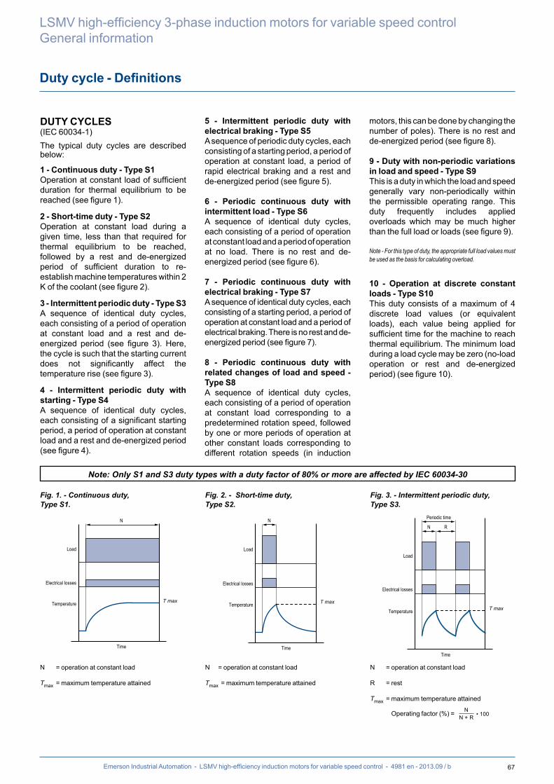
67Emerson Industrial Automation - LSMV high-efficiency induction motors for variable speed control - 4981 en - 2013.09 / b
LSMV high-efficiency 3-phase induction motors for variable speed controlGeneral information
Duty cycle - Definitions
DUTY CYCLES(IEC 60034-1)The typical duty cycles are described below:
1 - Continuous duty - Type S1Operation at constant load of sufficient duration for thermal equilibrium to be reached (see figure 1).
2 - Short-time duty - Type S2Operation at constant load during a given time, less than that required for thermal equilibrium to be reached, followed by a rest and de-energized period of sufficient duration to re-establish machine temperatures within 2 K of the coolant (see figure 2).
3 - Intermittent periodic duty - Type S3A sequence of identical duty cycles, each consisting of a period of operation at constant load and a rest and de-energized period (see figure 3). Here, the cycle is such that the starting current does not significantly affect the temperature rise (see figure 3).
4 - Intermittent periodic duty with starting - Type S4A sequence of identical duty cycles, each consisting of a significant starting period, a period of operation at constant load and a rest and de-energized period (see figure 4).
5 - Intermittent periodic duty with electrical braking - Type S5 A sequence of periodic duty cycles, each consisting of a starting period, a period of operation at constant load, a period of rapid electrical braking and a rest and de-energized period (see figure 5).
6 - Periodic continuous duty with intermittent load - Type S6A sequence of identical duty cycles, each consisting of a period of operation at constant load and a period of operation at no load. There is no rest and de-energized period (see figure 6).
7 - Periodic continuous duty with electrical braking - Type S7A sequence of identical duty cycles, each consisting of a starting period, a period of operation at constant load and a period of electrical braking. There is no rest and de-energized period (see figure 7).
8 - Periodic continuous duty with related changes of load and speed - Type S8A sequence of identical duty cycles, each consisting of a period of operation at constant load corresponding to a predetermined rotation speed, followed by one or more periods of operation at other constant loads corresponding to different rotation speeds (in induction
motors, this can be done by changing the number of poles). There is no rest and de-energized period (see figure 8).
9 - Duty with non-periodic variations in load and speed - Type S9This is a duty in which the load and speed generally vary non-periodically within the permissible operating range. This duty frequently includes applied overloads which may be much higher than the full load or loads (see figure 9).
Note - For this type of duty, the appro priate full load values must be used as the basis for calculating overload.
10 - Operation at discrete constant loads - Type S10This duty consists of a maximum of 4 discrete load values (or equivalent loads), each value being applied for sufficient time for the machine to reach thermal equilibrium. The minimum load during a load cycle may be zero (no-load operation or rest and de-energized period) (see figure 10).
Load
Electrical losses
Temperature
Time
N
T max
Load
Electrical losses
Temperature
Time
N
T max
Load
Electrical losses
Temperature
Time
N
T max
R
Periodic time
Note: Only S1 and S3 duty types with a duty factor of 80% or more are affected by IEC 60034-30
N = operation at constant load
Tmax = maximum temperature attained
N = operation at constant load
Tmax = maximum temperature attained
N = operation at constant load
R = rest
Tmax = maximum temperature attained
Operating factor (%) = N• 100N + R
N• 100N + V
D + N1 100 %D + N1 + F1 + N2 + F2 + N3
F1 + N2 100 %D + N1 + F1 + N2 + F2 + N3
F2 + N3 100 %D + N1 + F1 + N2 + F2 + N3
LN
D + N• 100N + R + D
D + N + F• 100D + N + F + R
Fig. 1. - Continuous duty,Type S1.
Fig. 2. - Short-time duty,Type S2.
Fig. 3. - Intermittent periodic duty,Type S3.

68 Emerson Industrial Automation - LSMV high-efficiency induction motors for variable speed control - 4981 en - 2013.09 / b
Duty cycle - Definitions
LSMV high-efficiency 3-phase induction motors for variable speed controlGeneral information
Fig. 4. - Intermittent periodic dutywith starting, Type S4.
Fig. 5. - Intermittent periodic duty with electrical braking, Type S5.
Fig. 6. - Periodic continuous dutywith intermittent load, Type S6.
D = starting
N = operation at constant load
R = rest
Tmax = maximum temperature attained during cycle
Operating factor (%) = N
• 100N + R
N• 100N + V
D + N1 100 %D + N1 + F1 + N2 + F2 + N3
F1 + N2 100 %D + N1 + F1 + N2 + F2 + N3
F2 + N3 100 %D + N1 + F1 + N2 + F2 + N3
LN
D + N• 100N + R + D
D + N + F• 100D + N + F + R
D = starting
N = operation at constant load
F = electrical braking
R = rest
Tmax = maximum temperature attained during cycle
Operating factor (%) = N
• 100N + R
N• 100N + V
D + N1 100 %D + N1 + F1 + N2 + F2 + N3
F1 + N2 100 %D + N1 + F1 + N2 + F2 + N3
F2 + N3 100 %D + N1 + F1 + N2 + F2 + N3
LN
D + N• 100N + R + D
D + N + F• 100D + N + F + R
N = operation at constant load
V = no-load operation
Tmax = maximum temperature attained during cycle
Operating factor (%) =
N• 100N + R
N• 100N + V
D + N1 100 %D + N1 + F1 + N2 + F2 + N3
F1 + N2 100 %D + N1 + F1 + N2 + F2 + N3
F2 + N3 100 %D + N1 + F1 + N2 + F2 + N3
LN
D + N• 100N + R + D
D + N + F• 100D + N + F + R
Fig. 7. - Periodic continuous dutywith electrical braking, Type S7.
Fig. 8. - Periodic continuous duty with related changes of load and speed,Type S8.
F1F2 = electrical braking
D = starting
N1N2N3 = operation at constant loads
Tmax = maximum temperature attained during cycle
Operating factor =
N• 100N + R
N• 100N + V
D + N1 100 %D + N1 + F1 + N2 + F2 + N3
F1 + N2 100 %D + N1 + F1 + N2 + F2 + N3
F2 + N3 100 %D + N1 + F1 + N2 + F2 + N3
LN
D + N• 100N + R + D
D + N + F• 100D + N + F + R
D = starting
N = operation at constant load
F = electrical braking
Tmax = maximum temperature attained during cycle
Operating factor = 1
Load
Electrical losses
Temperature
Time
N
T max
R
Periodic time
D
Load
Electrical losses
Temperature
Time
N
T max
R
Periodic time
D FLoad
Electrical losses
Temperature
Time
N
T max
V
Periodic time
Load
Electrical losses
Temperature
Time
N
T max
F
Periodic time
D
Load
Electrical losses
Temperature
Time
N1
T max
N2
Periodic time
D
Speed
F1 F2 N3

69Emerson Industrial Automation - LSMV high-efficiency induction motors for variable speed control - 4981 en - 2013.09 / b
LSMV high-efficiency 3-phase induction motors for variable speed controlGeneral information
Duty cycle - Definitions
Fig. 9. - Duty with non-periodic variations in load and speed, Type S9.
Fig. 10 - Duty at discrete constant loads,Type S10.
D = starting
L = operation at variable loads
F = electrical braking
R = rest
S = operation at overload
Cp = full load
Tmax = maximum temperature attained
L = load
N = rated power for type S1 duty
p = p /
N• 100N + R
N• 100N + V
D + N1 100 %D + N1 + F1 + N2 + F2 + N3
F1 + N2 100 %D + N1 + F1 + N2 + F2 + N3
F2 + N3 100 %D + N1 + F1 + N2 + F2 + N3
LN
D + N• 100N + R + D
D + N + F• 100D + N + F + R
= reduced load
t = time
Tp = total cycle time
ti = discrete period within a cycle
Dti = ti / Tp = relative duration of period within a cycle
Pu = electrical losses
HN = temperature at rated power for type S1 duty
DHi = increase or decrease in temperature rise during the ith period of the cycle
Speed
Electrical losses
Temperature
Time
T max
L
LoadCp
FD
R
S
1
TT
T
TH
Temperature
1
Electrical losses
t1
t
LoadL1
L2L3
t2 t3 t4
P4
Time
L1
Power is determined according to duty cycle. See “Operation” section, “Power - Torque - Efficiency - Power Factor (Cos )” paragraph.

70 Emerson Industrial Automation - LSMV high-efficiency induction motors for variable speed control - 4981 en - 2013.09 / b
Identification
LSMV high-efficiency 3-phase induction motors for variable speed controlGeneral information
Please quote when ordering spare parts
NAMEPLATES
LSMV 132 M IE2 LSMV 132 M
DEFINITION OF SYMBOLS USED ON NAMEPLATESLegal mark of conformity of product to the requirements of European Directives
Conformity of product to the requirements of Canadian and American Directives
CE68554-G
US
MOT 3 ~ : Three-phase A.C. motor LSMV : Series 132 : Frame size M : Housing symbol T : Impregnation index
Motor no. 999999 : Motor batch number N : Month of production 12 : Year of production 0001 : Serial number
IE2 : Efficiency class 89.2% : Efficiency at 4/4 load
IP55 IK08 : Ingress protectionI cl. F : Insulation class F40°C : Ambient operating
temperatureS1 or S9 : Duty - Duty (operating) factorkg : WeightV : Supply voltageHz : Supply frequencymin-1 : Revolutions per minute (rpm)kW : Rated output powercos j : Power factorA : Rated current - Plate 1: on the mains - Plate 2: on frequency
inverterD : Delta connectionY : Star connection
Bearings
DE : Drive end bearingNDE : Non drive end bearing
B : Vibration level
H : Balancing mode
Plate 1 Plate 2

71Emerson Industrial Automation - LSMV high-efficiency induction motors for variable speed control - 4981 en - 2013.09 / b
LSMV high-efficiency 3-phase induction motors for variable speed controlGeneral information
Configurator
The configurator can be used to choose the most suitable motor and provides the technical specifications and corres-ponding drawings.
Register online at:www.leroy-somer.com/en/solutions_a n d _ s e r v i c e s / d r i v e _ s y s t e m s /configurator
• Help with product selection• Print-outs of technical specifications• Print-outs of 2D and 3D CAD files• The equivalent of 300 catalogues in 10
languages
Being able both to respond to urgent requests and adhere to promised customer lead times calls for a powerful logistics system.The availability of motors is ensured by the network of approved partners and Leroy-Somer central services all working together.The selection data in the "Guaranteed Availability Drive systems" catalogue specify for each family in the form of a colour code and according to the
quantities per order, the product delivery time.
Please consult Leroy-Somer.
Product availability

72 Emerson Industrial Automation - LSMV high-efficiency induction motors for variable speed control - 4981 en - 2013.09 / b
LSMV high-efficiency 3-phase induction motors for variable speed control
Notes

73Emerson Industrial Automation - LSMV high-efficiency induction motors for variable speed control - 4981 en - 2013.09 / b
LSMV high-efficiency 3-phase induction motors for variable speed control
Notes

74 Emerson Industrial Automation - LSMV high-efficiency induction motors for variable speed control - 4981 en - 2013.09 / b
LSMV high-efficiency 3-phase induction motors for variable speed control
Notes


- 201
3.10
/ i
The Emerson logo is a trademark and service mark of Emerson Electric Co. © 2013
Moteurs Leroy-Somer SAS - RCS 338 567 258 ANGOULÊME - Capital de 65 800 512 €
en- 2
013.
10 /
ien
www.emersonindustrial.com
© - This document is the property of Emerson Industrial Automation, it can not be reproduced in any form without prior written authorization.Emerson Industrial Automation reserves the right to modify the design, technical speci�cations and dimensions of the products shown in this document.
The descriptions cannot in any way be considered contractual.