HIGH CAPACITY ADAPTIVE BASE-STATION … CAPACITY ADAPTIVE BASE-STATION ANTENNA SYSTEMS Anders G...
21
Ericsson Research ©2002 Ericsson AB ISART´02, 4-6 March 2002, A Derneryd HIGH CAPACITY ADAPTIVE BASE-STATION ANTENNA SYSTEMS Anders G Derneryd Ericsson AB Antenna Research Center SE-431 84 Molndal, Sweden Email: [email protected]
Transcript of HIGH CAPACITY ADAPTIVE BASE-STATION … CAPACITY ADAPTIVE BASE-STATION ANTENNA SYSTEMS Anders G...

Ericsson Research ©2002 Ericsson ABISART´02, 4-6 March 2002, A Derneryd
HIGH CAPACITY ADAPTIVE BASE-STATIONANTENNA SYSTEMS
Anders G Derneryd
Ericsson ABAntenna Research Center
SE-431 84 Molndal, Sweden
Email: [email protected]

Ericsson Research ©2002 Ericsson ABISART´02, 4-6 March 2002, A Derneryd
Outline
• Background• Adaptive Antenna Systems
GSM (Global Systems for Mobile Communications)GPRS (General Packet Radio Service)
EDGE ( (Enhanced Data Rates for Global Evolution)WCDMA (Wideband Code Division Multiple Access)
• Hardware realization• Conclusions

Ericsson Research ©2002 Ericsson ABISART´02, 4-6 March 2002, A Derneryd
Background
Growth fromprevious year
• Increased mobilesubscribers growth
• To satisfy capacitydemand, new technologyis needed
• Conventional ways toincrease capacity
½ More radio spectrum: Regulatory limitations and high costs ! New terminals !
½ Cell splitting: High costs of acquring new sites & infastructure !
½ Higher degree of sectorization: Increased number of hand-offs !

Ericsson Research ©2002 Ericsson ABISART´02, 4-6 March 2002, A Derneryd
Technology for Advanced Antenna Systems
Incr
ease
d implem
enta
tion co
mplex
ity an
d cost
Basic three-sector sites
Higher order sectorization
Fixed multi-beam antenna
Steered beam antenna

Ericsson Research ©2002 Ericsson ABISART´02, 4-6 March 2002, A Derneryd
GSM Adaptive Antenna Concept
Array antenna
Interferer
Interferer
Desired
• Narrow beams are directed fromthe base-station towards themobile stations
• A beam can be (steered towardsthe desired mobile station or)selected from a set of fixed beams
• The beam for downlinktransmission is determined oninformation derived from the uplink,the direction of arrival (DOA)
Adaptive AntennaSystem
Reduced Interference
Tight FrequencyReuse Possible
Large CapacityIncrease

Ericsson Research ©2002 Ericsson ABISART´02, 4-6 March 2002, A Derneryd
GSM Multi-Beam Adaptive Antenna System
Ericsson implementation
• Low complexity adaptive antenna system solution
• Non-coherent radio chains
• 8 fixed narrow interleaved beams per 120° sector
• RF level beamforming, with no calibration requirement
• Best beams selected for uplink combining
• Best beam selected for downlink transmission

Ericsson Research ©2002 Ericsson ABISART´02, 4-6 March 2002, A Derneryd
GSM Capacity Booster, RBS 2205
Radio base-station 8-beam array antenna

Ericsson Research ©2002 Ericsson ABISART´02, 4-6 March 2002, A Derneryd
Capacity Increase with GSM Adaptive Antenna
0
10
20
30
40
50
60
70
80
0 2 4 6 8 10 12 14 16 18 20 22 24 26 28 30 32
Adaptive Ant. Sol. cells introduced in network [% of total number of cells]
Cap
acity
Gai
n [%
]
&DSDFLW\�JDLQLQWURGXFLQJ�DGDSWLYH
DQWHQQD�VROXWLRQ�LQWR�DkUHDOy�QHWZRUN
,QWURGXFLQJ�$$�VROXWLRQLQWR�D�KRPRJHQHRXV
QHWZRUN
,QWURGXFLQJ�VWDQGDUGVLWHV
�YLD�kFHOO�VSOLWWLQJy�
Cap
acit
y in
crea
se (
%)
Adative antenna systems introduced in network (% of total number of cells)

Ericsson Research ©2002 Ericsson ABISART´02, 4-6 March 2002, A Derneryd
GSM Adaptive Antenna Characteristics
• Tailored antenna beams reduce interference levels and enablea tighter frequency reuse pattern
• Live field trials show a capacity increase of more than 100% atsites using GSM adaptive antennas
• Substantial network capacity increase can be achieved byintroducing adaptive antennas in only a limited number of sites
Goal: Reduce Operator Infrastructure Cost

Ericsson Research ©2002 Ericsson ABISART´02, 4-6 March 2002, A Derneryd
I
Q
(0,1,1)
(1,1,0)(1,0,1)
(0,0,0)
(0,0,1) (1,1,1)
(1,0,0)
(0,1,0)
I
Q
“1”
“0”
EDGE EDGE IntroducesIntroduces a Newa New Modulation Modulation
GPRS:GMSK Modulation
EDGE:8PSK Modulation
1 bit per symbol 3 bits per symbol

Ericsson Research ©2002 Ericsson ABISART´02, 4-6 March 2002, A Derneryd
Basic Technical Parameters
GPRS EDGE
Modulation GMSK 8-PSK
Symbol rate 270 ksym/s 270 ksym/s
Modulation bit rate 270 kb/s 810 kb/s
Radio data rate per time slot 22.8 kb/s 69.2 kb/s
User data rate per time slot 20 kb/s 59.2 kb/s
User data rate @ 8 time slots 160 kb/s 473.6 kb/s
(including header bits) (182.4 kb/s1)) (553.6 kb/s1))
1) Usually specifed at 115 kbps and 384 kbps, respectively.

Ericsson Research ©2002 Ericsson ABISART´02, 4-6 March 2002, A Derneryd
C/I Simulation Results for EDGE
−10 0 10 20 30 40 50 600
10
20
30
40
50
60
70
80
90
100
C.D
.F. [
%]
C/I [dB]
Sec, 35 usersSec, 50 usersAA, 35 users AA, 50 users AA, 65 users
• www-traffic model
• Link-adaptation inactive
• Same amount of traffic
• No protocol aspects considered
15 dB
C/I (dB)
CD
F (
%)

Ericsson Research ©2002 Ericsson ABISART´02, 4-6 March 2002, A Derneryd
9.6 -14.4 kb/s
57.6 kb/s
115 kb/s
384 kb/s
GPRS
HSCSD
EDGE
CS
• No new license required
• Short time to market
• Low investment costs
• Capacity tripled
• Data rates tripled
EDGE Achievements
Ericsson Research ©2002 Ericsson ABISART´02, 4-6 March 2002, A Derneryd
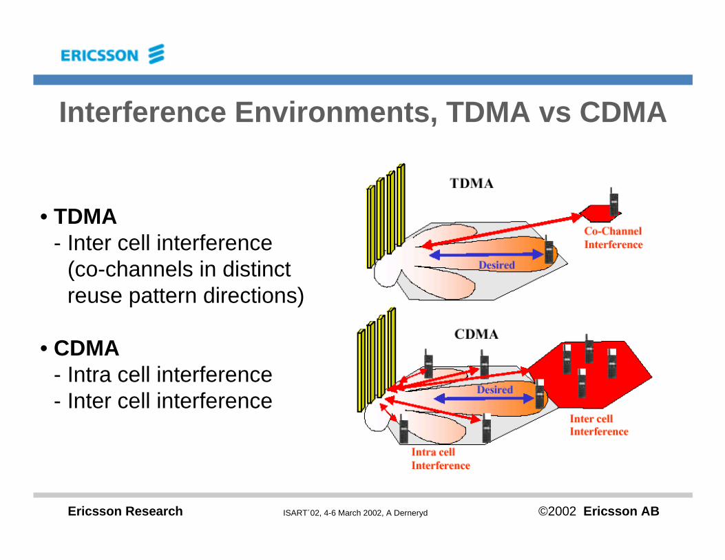
Interference Environments, TDMA vs CDMA
• TDMA- Inter cell interference
(co-channels in distinct reuse pattern directions)
• CDMA- Intra cell interference- Inter cell interference

Ericsson Research ©2002 Ericsson ABISART´02, 4-6 March 2002, A Derneryd
WCDMA Downlink C/I Simulation
C/I (dB)
CD
F (
%)

Ericsson Research ©2002 Ericsson ABISART´02, 4-6 March 2002, A Derneryd
Cylindrical vs. Planar Multi-Beam Antennas
−20 −10 0
30
210
60
240
90
270
120
300
150
330
180 0 −20 −10 0
30
210
60
240
90
270
120
300
150
330
180 0
d 1.15 d

Ericsson Research ©2002 Ericsson ABISART´02, 4-6 March 2002, A Derneryd
Cylindrical Array Antenna Example

Ericsson Research ©2002 Ericsson ABISART´02, 4-6 March 2002, A Derneryd
Cylindrical Omni-Directional Array Antenna
-20
-15
-10
-5
0
30
210
60
240
90
270
120
300
150
330
180 0
l 12 radiating columns
l 2 wavelength diameter
l 0.5 wavelength spacing
l all columns fed
l in-phase excitation

Ericsson Research ©2002 Ericsson ABISART´02, 4-6 March 2002, A Derneryd
Cylindrical Multi-Beam Array Antenna
l 12 radiating columns
l 2 wavelength diameter
l 0.5 wavelength spacing
l 5 fed columns
l co-phasal excitation
−20 −10 0
30
210
60
240
90
270
120
300
150
330
180 0

Ericsson Research ©2002 Ericsson ABISART´02, 4-6 March 2002, A Derneryd
Cylindrical Array Antenna Trade-Offs
l Radiation pattern types– Omni-directional beam for coverage and/or broadcast– Narrow multi-beams for capacity
l Cylinder radius and number of radiating elements– Radiation pattern ripple in azimuth with omni coverage– Number of directional beams in azimuth for capacity– Sidelobe level

Ericsson Research ©2002 Ericsson ABISART´02, 4-6 March 2002, A Derneryd
Adaptive Base-Station Antenna SystemConclusions
l Less interference transmitted– Minimize interference spread in downlink
l Enable receiver interference suppression– Possibility to utilize spatial separation in uplink
l Adaptive antenna systems show substantial performance improvements
l Grow-on-site capacity increase in existing networks– No new additional sites– Site-by-site migration strategy