High-Capacity 24 GHz Unlicensed Band Wireless … 24 GHz Unlicensed Band Wireless Ethernet System...
130
AirPair TM 100-UL High-Capacity 24 GHz Unlicensed Band Wireless Ethernet System Product Manual Version 2.0
Transcript of High-Capacity 24 GHz Unlicensed Band Wireless … 24 GHz Unlicensed Band Wireless Ethernet System...
AirPairTM
100-UL
High-Capacity 24 GHz Unlicensed Band Wireless Ethernet System Product Manual
Version 2.0
ii DragonWave Inc.
NOTICE This document contains confidential information, which is proprietary to DragonWave. No part of its contents can be used, copied, disclosed, or conveyed to any party in any manner whatsoever without prior written permission from DragonWave Inc.
Copyright © 2001-2003 DragonWave Inc. All Rights Reserved. Printed in Canada.
Table of Contents TABLE OF CONTENTS ...........................................................................................................III LIST OF PROCEDURES.......................................................................................................... V LIST OF FIGURES ................................................................................................................. VII LIST OF TABLES................................................................................................................... VII 1. INTRODUCTION ....................................................................................................................1 1.1.....REFERENCES ..................................................................................................................................2 1.2.....ICONS .............................................................................................................................................3 2. SAFETY AND REGULATORY COMPLIANCE .....................................................................5 2.1.....SAFETY INFORMATION ...................................................................................................................5
2.1.1. SAFETY INFORMATION FOR DRAGONWAVE’S AIRPAIRTM ..........................................................5 2.1.2. INSTALLATIONS ..........................................................................................................................5 2.1.3. LIGHTNING PROTECTION ............................................................................................................5 2.1.4. ELECTROCUTION HAZARD ..........................................................................................................6
2.2.....REGULATORY COMPLIANCE INFORMATION....................................................................................6 2.2.1. FEDERAL COMMUNICATION COMMISSION DECLARATION OF CONFORMITY STATEMENT...........6 2.2.2. PROFESSIONAL INSTALLATION ...................................................................................................7
3. WARRANTY...........................................................................................................................9 3.1.....GENERAL TERMS............................................................................................................................9 3.2.....HARDWARE ....................................................................................................................................9 3.3.....SOFTWARE ...................................................................................................................................10 3.4.....RETURN OF EQUIPMENT UNDER WARRANTY ...............................................................................10 3.5.....DEFAULT AND TERMINATION.......................................................................................................11 3.6.....FORCE MAJEURE ..........................................................................................................................11 3.7.....ENGINEERING AND SYSTEM DESIGN.............................................................................................12 4. DESCRIPTION .....................................................................................................................13 4.1.....AIRPAIR 100-UL SPECIFICATIONS ...............................................................................................14 4.2.....CALCULATING THE LINK BUDGET................................................................................................14
4.2.1. POWER OUTPUT........................................................................................................................15 4.3.....COMMAND LINE INTERFACE ........................................................................................................15
4.3.1. CONFIGURING THE SERIAL PORT USING THE CLI......................................................................15 4.3.2. CREATE LOGIN ACCOUNT.........................................................................................................17
4.4.....SET AIRPAIR FREQUENCY ............................................................................................................20 4.5.....SET IP ADDRESS ...........................................................................................................................27 4.6.....VLAN TAGGING...........................................................................................................................30 5. INSTALLATION....................................................................................................................33
iv DragonWave Inc.
5.1.....BEFORE YOU BEGIN ......................................................................................................................33 5.2.....MOUNTING SPECIFICATIONS.........................................................................................................33 6. INSTALLATION OF RADIO AND MODEM .........................................................................35 6.1.....MOUNTING THE RADIO AND ANTENNA ONTO THE MOUNTING BRACKET.....................................35 6.2.....VISUALLY-ALIGNING RADIOS.......................................................................................................37 6.3.....FINE-ADJUST ALIGNMENT OF THE RADIOS ....................................................................................45
6.3.1. MAIN LOBE AND SIDE LOBES OF RADIO WAVES ......................................................................45 6.4.....CLEAR LINE OF SIGHT ..................................................................................................................47 6.5.....FINE-ADJUST ALIGN THE RADIOS ..................................................................................................48
6.5.1. PERFORM A DATA TEST ............................................................................................................49 6.5.2. CONNECT TO THE LAN.............................................................................................................50
7. SETTING UP THE SNMP.....................................................................................................51 7.1.1. AIRPAIR ENTERPRISE MANAGEMENT INFORMATION BASE ......................................................53 7.1.2. TRAPS .......................................................................................................................................53
8. TECHNICAL SUPPORT.......................................................................................................57 9. NOTICE ................................................................................................................................59 9.1.....COPYRIGHT ..................................................................................................................................59 APPENDIX A - FREQUENCY CHANNEL PLANS..............................................................61 APPENDIX B - MOUNTING INSTRUCTIONS FOR 30 CM, 60 CM, 90CM ANTENNAS...63 APPENDIX C - COMMAND LINE INTERFACE (CLI) .........................................................65 COMMANDS FOR INITIAL SYSTEM CONFIGURATION................................................................................67 COMMAND SYNTAX SUMMARY ..............................................................................................................76 COMPLETE LIST OF CLI COMMANDS ......................................................................................................79 ALARMS................................................................................................................................................120
AirPair 100UL 24GHz Product Manual
Table of Contents v
List of Procedures Procedure 4-1 Configuring the Serial Port using the CLI 15 Procedure 4-2 Create Login Account 18 Procedure 4-3 Set AirPair Frequency available and Transmit Power 20 Procedure 4-5 Setting the IP Address 28 Procedure 4-6 Setting VLAN Tag 31 Procedure 6-1 Mounting the 12″ antennas 35 Procedure 6-2 Visually align the radios 37 Procedure 6-3 Attaching the Modem to Mounting Bracket 38 Procedure 6-4 Connecting the IF and RS-232 cable to the modem and radio 42 Procedure 6-5 Connect the power cable to the modem and the power pack 44 Procedure 6-6 Fine-adjust Align Radios 48 Procedure 6-7 Perform a data test 50 Procedure 7-1 Setting up SNMP 51 Procedure 7-2 Enable traps 53 Procedure C - 1 Configure the serial port 65
Version 2.0

vi DragonWave Inc.
This page is intentionally blank.
AirPair 100UL 24GHz Product Manual
Table of Contents vii
List of Figures Figure 1 DragonWave AirPair Systems ...........................................................................1 Figure 2 AirPair System .................................................................................................13 Figure 3 Use of Visual Alignment Tool............................................................................37 Figure 4 Modem on Mounting Bracket ............................................................................38 Figure 5 Modem..............................................................................................................39 Figure 6 Modem connected to Radios and 12″, 24″ and 36″ antennas 24 GHz system
with 12” dish.....................................................................................................40 Figure 7 Alternative mount for 12″ antennas ..................................................................40 Figure 8 24 GHz system with 24” antenna mounted.......................................................41 Figure 9 24 GHz system with 36” antenna mounted.......................................................42 Figure 10 6-LED Panel on Modem..................................................................................44 Figure 11 2 Degree Beamwidth ......................................................................................45 Figure 12 Main and Side Lobes - Radio Signal Using 12″/30 cm Antenna.....................46 Figure 13 WRONG! Obstruction of the Fresnel Zone .....................................................47 Figure 14 WRONG! Trees within the Fresnel Zone Obstruct the Signal.........................47
List of Tables Table 1 Power Output 15 Table 2 Mounting Pole Specifications for SKED 80 Steel Pipe 33 Table 3 Torque Specifications for mounting modem to bracket 38 Table 4 Available Standard Frequencies 61 Table 5 Available Customized Frequencies 62 Table 6 NOC and ADMIN Creation Account Privileges 66
Version 2.0

viii DragonWave Inc.
This page is intentionally left blank.
AirPair 100UL 24GHz Product Manual
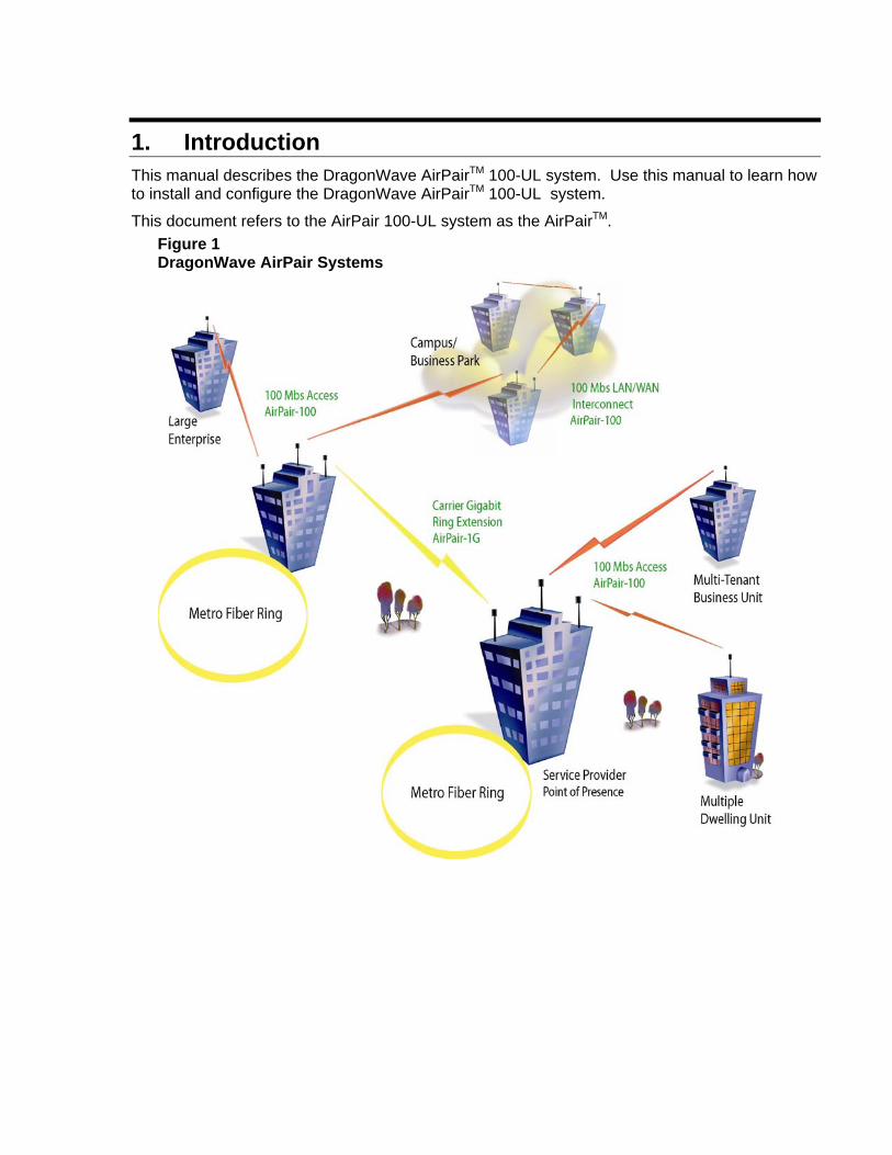
1. Introduction This manual describes the DragonWave AirPairTM 100-UL system. Use this manual to learn how to install and configure the DragonWave AirPairTM 100-UL system.
This document refers to the AirPair 100-UL system as the AirPairTM. Figure 1 DragonWave AirPair Systems
2 DragonWave Inc.
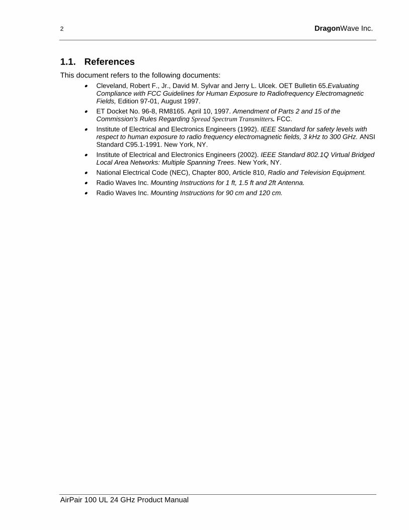
1.1. References This document refers to the following documents:
• Cleveland, Robert F., Jr., David M. Sylvar and Jerry L. Ulcek. OET Bulletin 65.Evaluating Compliance with FCC Guidelines for Human Exposure to Radiofrequency Electromagnetic Fields, Edition 97-01, August 1997.
• ET Docket No. 96-8, RM8165. April 10, 1997. Amendment of Parts 2 and 15 of the Commission's Rules Regarding Spread Spectrum Transmitters. FCC.
• Institute of Electrical and Electronics Engineers (1992). IEEE Standard for safety levels with respect to human exposure to radio frequency electromagnetic fields, 3 kHz to 300 GHz. ANSI Standard C95.1-1991. New York, NY.
• Institute of Electrical and Electronics Engineers (2002). IEEE Standard 802.1Q Virtual Bridged Local Area Networks: Multiple Spanning Trees. New York, NY.
• National Electrical Code (NEC), Chapter 800, Article 810, Radio and Television Equipment. • Radio Waves Inc. Mounting Instructions for 1 ft, 1.5 ft and 2ft Antenna. • Radio Waves Inc. Mounting Instructions for 90 cm and 120 cm.
AirPair 100 UL 24 GHz Product Manual
Introduction 3
1.2. Icons The following icons appear in this manual and highlight areas of special interest and importance.
Warning Cause Bodily Harm
Caution Cause damage to equipment or service outage
Information or Note Important Information
Version 2.0

4 DragonWave Inc.
This page is intentionally left blank.
AirPair 100 UL 24 GHz Product Manual
2. Safety and Regulatory Compliance This section details safety issues and regulatory compliance.
2.1. Safety Information
2.1.1. Safety Information for DragonWave’s AirPairTM The Federal Communications Commission (FCC), with its action in ET Docket 96-8, has adopted a safety standard for human exposure to radio frequency (RF) electromagnetic energy emitted by FCC-certified equipment. DragonWave AirPairTM meets the uncontrolled environmental limits found in OET-65 and ANSI C95.1, 1991. Proper operation of this radio according to the instructions found in this manual and the users guide for the DragonWave AirPairTM product will result in user exposure that is substantially below the FCC recommended limits.
• Do not touch or move antenna(s) while the unit is transmitting or receiving.
• While transmitting, do not hold any component containing the radio in such a way that the antenna is very close to or touching any exposed parts of the body, especially the face or eyes.
• Do not operate a portable transmitter near unshielded blasting caps or in an explosive environment unless it is a type especially qualified for such use.
The design of the high-gain mast mount antennas is such that professional installation is required.
2.1.2. Installations DragonWave AirPairTM devices require professional installation. It is the responsibility of the installer to be sure that all building and safety codes are met and that the installation is complete and secure.
For Canadian installations, the entire equipment installation must comply with Canadian Standard CSA 22.2, No. 60950, Safety of Information Technology Equipment. For installations in the United States, the entire equipment installation must be in accordance with Article 810 of the United States National Electrical Code.
2.1.3. Lightning Protection When installed, this equipment is to be connected to a Lightning/Surge Protection Device that meets all applicable national safety requirements.
6 DragonWave Inc.
2.1.4. Electrocution Hazard
Warning Electrocution Hazard
This product is intended to be connected to a –48v dc power source (supplied by DragonWave Inc.), which must be electrically isolated from any ac sources and reliably connected to Earth ground. Do not install DragonWave products near any type of power line. Should your antenna or related hardware come in contact with power lines, severe bodily harm or death could result!
2.2. Regulatory Compliance Information This section contains information regarding regulatory compliance with the Federal Communication Commission, Department of Communications and the European Telecommunications Standards Institute applies to the DragonWave AirPairTM Radio Link.
2.2.1. Federal Communication Commission Declaration of Conformity Statement
This device complies with Part 15 of FCC Rules. Operation is subject to the following two conditions: (1) This device may not cause harmful interference, and (2) This device must accept any interference received, including interference that may cause undesired operation.
This equipment has been tested and found to comply with the limits of a Class B digital device, pursuant to Part 15 of FCC Rules. These limits are designed to provide reasonable protection against harmful interference in a residential installation. This equipment generates and can radiate radio-frequency energy and, if not installed and used in accordance with the instructions, may cause harmful interference to radio communications. However, there is no guarantee that interference will not occur in a particular installation. If this equipment does cause harmful interference to radio or television reception, which can be determined by turning the equipment off and on, the user is encouraged to try to correct the interference by one or more of the following measures.
• Reorient or relocate the receiving antenna
• Increase the separation between the equipment and receiver
• Connect the equipment into an outlet on a circuit different from that to which the receiver is connected
• Consult the dealer or an experienced radio/TV technician for help
Any changes or modifications not expressly approved by the party responsible for compliance could void the user’s authority to operate the equipment.
AirPair 100 UL 24 GHz Product Manual
Safety and Regulatory Compliance 7
Warning The Part 15 radio device operates on a non-interference basis with the other devices operating at this frequency. Any changes or modification to said product not expressly approved by DragonWave Inc. could void the user’s authority to operate this device.
2.2.2. Professional Installation As per the recommendation of the FCC, the installation of high-gain directional antennas to the system, which is intended to operate solely as a point-to-point system and whose total power exceeds the +36 dBm Effective Isotropic Radiated Power (EIRP), requires professional installation. It is the responsibility of the installer and the end user that the high power systems are operated strictly as a point-to-point system.
Version 2.0

8 DragonWave Inc.
This page is intentionally left blank.
AirPair 100 UL 24 GHz Product Manual
3. Warranty This section describes the warranty.
3.1. General Terms (a) All Definitions contained in DragonWave Inc.’s Terms and Conditions of Sale
apply to the Warranty.
(b) This Warranty applies to all original purchases of DragonWave Inc. manufactured equipment and accessories (collectively “Equipment”).
(c) This Warranty applies to the specifications contained in the most recent version of the manual for the model of Equipment purchased.
(d) This Warranty does not apply to the following items of Equipment:
(e) cables and connectors;
(f) visual alignment tool;
(g) fine adjust alignment tool; or
(h) non-DragonWave Inc. equipment or equipment that is not listed in DragonWave Inc.’s price book.
(i) The Customer acknowledges that DragonWave Inc. does not represent or warrant that the services provided by DragonWave Inc. under this Warranty will ensure uninterrupted or error-free operation of the Equipment.
(j) The effective period of this Warranty shall start on the date of shipment of the Equipment and shall end twelve (12) months later.
3.2. Hardware (a) DragonWave Inc. warrants that the Equipment, which is hardware, will be free
from defects in material and will comply with DragonWave Inc.’s normal standards of workmanship, for a period of twelve (12) months from the date of shipment.
(b) DragonWave Inc. shall incur no liability under the foregoing warranty unless:
(c) the allegedly defective Equipment is returned, prepaid, to DragonWave Inc. within fifteen (15) days of the date of discovery of the alleged defect, in accordance with DragonWave Inc.’s then current repair procedures; and
(d) DragonWave Inc.’s tests disclose that the alleged defect is due solely to defects in material or workmanship.
(e) The liability of DragonWave Inc. under this hardware warranty shall in any event be limited, at DragonWave Inc.’s option and expense, to either the repair or replacement of the defective Equipment, or the reimbursement of the purchase price by the Customer to DragonWave Inc. for the defective Equipment.
10 DragonWave Inc.
(f) In no event will DragonWave Inc. be liable for damage to the Equipment resulting from improper handling during or after shipment, misuse, neglect, improper installation, operation or repair (other than by authorized DragonWave Inc. personnel), alteration, accident, or for any other cause not attributable to defects in materials or workmanship on the part of DragonWave Inc.
3.3. Software (a) DragonWave Inc. warrants that any software supplied as a Product or as part of a
Product will function substantially in accordance with the functional description set out in the software documentation provided to the Customer for a period of ninety (90) days from the date of shipment to the Customer.
(b) DragonWave Inc.’s sole obligation and the Customer’s sole remedy for a breach of this warranty shall be DragonWave Inc.’s good faith efforts to rectify the non-conformity, or, if after reasonable efforts, DragonWave Inc. is unable to rectify the non-conformity, DragonWave Inc. shall accept return of the software and refund to Customer the purchase price thereof. This warranty is available only once in respect of each licensed software program. DragonWave Inc. shall have no obligation under this warranty if the software is modified or if the software is used with hardware or software not supplied or approved by DragonWave Inc.
(c) In no event shall DragonWave Inc.’s liability to the Customer or to any other party for breach of any of the foregoing warranties exceed the purchase price paid by the Customer to DragonWave Inc. for the defective hardware or software product.
(d) The express warranties set out in this warranty statement are in lieu of all other warranties, representations or conditions, expressed or implied, including implied warranties of merchantability or fitness for a particular purpose, or those arising from statute or usage of trade. The Customer shall not make any representations or warranties of any kind whatsoever relating to the Equipment or to DragonWave Inc. which exceed those made by DragonWave Inc. in this warranty statement.
3.4. Return of Equipment Under Warranty (a) If an item of Equipment malfunctions or fails in normal intended usage and
maintenance within the applicable Warranty Period:
(b) the Customer shall promptly notify DragonWave Inc. of the problem and the serial number of the defective item; and
(c) DragonWave Inc. shall, at its sole option, either resolve the problem over the telephone or provide the Customer with a Returned Materials Authorization (RMA) number and the address of the location to which the Customer can ship the defective item.
(d) If the problem is not resolved over the telephone, the Customer shall attach a DragonWave Repair and Return Form to each returned item describing the fault and the Customer’s return address. The Customer shall, at its cost, properly pack the item to be returned, prepay the insurance and shipping charges, and ship the item to the specified location.
AirPair 100 UL 24 GHz Product Manual
Warranty 11
(e) If the DragonWave Inc. equipment shall prove to be defective in material or workmanship upon examination by DragonWave Inc., DragonWave Inc. shall either repair or replace the returned item at its sole option. The replacement item can be new or refurbished; if refurbished, it shall be equivalent in operation to new Equipment. If a returned item is replaced by DragonWave Inc., the Customer agrees that the returned item shall become the property of DragonWave Inc.
(f) DragonWave Inc. shall, at its cost, ship the repaired item or replacement to any destination within the United States of America (USA) or within Canada by carrier and method of delivery chosen by DragonWave Inc. If the Customer has requested some other form of conveyance, such as express shipping, or is located beyond the borders of the USA or Canada, then the Customer shall pay the cost of return shipment.
3.5. Default and Termination (a) DragonWave Inc. can immediately terminate this Warranty and all of its
performance under this Warranty, upon notification to the Customer, if the Customer:
(b) makes any unauthorized modifications to the Equipment;
(c) violates or allows others to violate, the protection afforded DragonWave Inc. under applicable Canadian and international copyright laws. Violation of copyright shall include, but not be limited to, copying, translating, modifying, creating derivative works, reverse engineering, decompiling or otherwise using the Equipment except as expressly permitted by written consent from DragonWave Inc.;
(d) assigns or transfers the Customer’s rights or obligations under this Warranty without the written consent of DragonWave Inc.:
1. Becomes bankrupt or insolvent, or is put into receivership; or
2. Has not paid DragonWave Inc. all amounts for the Equipment, services or other additional charges within thirty (30) days’ receipt of written notice from DragonWave Inc.
(e) If this Warranty is terminated by DragonWave Inc., the Customer shall remain liable for all amounts due DragonWave Inc.
3.6. Force Majeure (a) DragonWave Inc. shall not be liable if its performance of the Terms and
Conditions of Sale becomes commercially impractical due to any contingency beyond DragonWave Inc.’s reasonable control, including acts of God, fires, floods, wars, sabotage, civil unrest, accidents, labour disputes or shortages, government laws, rules and regulations, whether valid or invalid, inability to obtain material, equipment or transportation, incorrect, delayed or incomplete specifications, drawings or data supplied by Customers or others (collectively “Force Majeure”). In no event of Force Majeure shall DragonWave be required to purchase goods from others to enable it to deliver the Equipment under the Terms and Conditions of Sale.
(b) DragonWave Inc. shall not be responsible for failure to discharge its obligations under this Warranty due to Force Majeure.
Version 2.0
12 DragonWave Inc.
3.7. Engineering and System Design (a) The Customer is solely responsible for the engineering, design, integration and
normal preventative and remedial maintenance of the Customer’s system for which DragonWave Inc. supplies Equipment.
(b) DragonWave Inc. is not responsible for the satisfactory operation of the Equipment in conjunction with other manufacturer’s equipment, nor for any losses, which can occur as a result of a failure of the Equipment to operate in conjunction with another manufacturer’s equipment.
AirPair 100 UL 24 GHz Product Manual
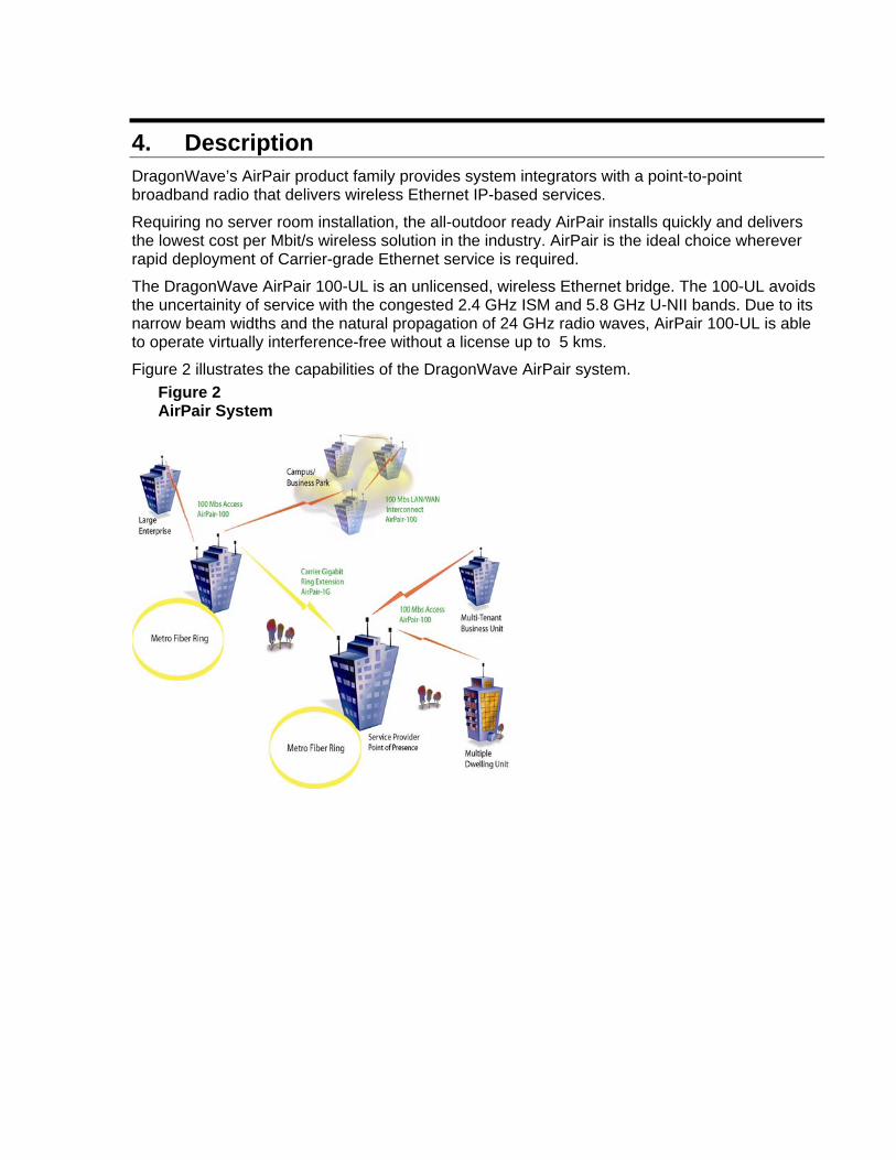
4. Description DragonWave’s AirPair product family provides system integrators with a point-to-point broadband radio that delivers wireless Ethernet IP-based services.
Requiring no server room installation, the all-outdoor ready AirPair installs quickly and delivers the lowest cost per Mbit/s wireless solution in the industry. AirPair is the ideal choice wherever rapid deployment of Carrier-grade Ethernet service is required.
The DragonWave AirPair 100-UL is an unlicensed, wireless Ethernet bridge. The 100-UL avoids the uncertainity of service with the congested 2.4 GHz ISM and 5.8 GHz U-NII bands. Due to its narrow beam widths and the natural propagation of 24 GHz radio waves, AirPair 100-UL is able to operate virtually interference-free without a license up to 5 kms.
Figure 2 illustrates the capabilities of the DragonWave AirPair system. Figure 2 AirPair System
14 DragonWave Inc.
4.1. AirPair 100-UL Specifications The AirPair 100-UL specifications are:
• Network Ready
• Wirespeed 100 Mbps full duplex
• SNMP-, HTTP-based network management
• Carrier Grade
• As high as 99.999% availability to meet or exceed wireline standards
• Secure encryption standard
• Designed for rugged outdoor use
• 24 GHz Unlicensed Band
• Compliant with FCC Standards
• Cost Effective
• Engineered for rapid installation with no indoor space requirements
• No cable trenching required
• Target Applications
• Inter-building LAN extension
• Wireless ISP backhaul
• Fiber Path Redundancy
• Homeland Security
• Disaster Recover
• Packaging
• Pole, tower or rooftop mast mounts
• Antennas offered in 12”, 24” and 36” formats
• Cross-Polarized mounting
• Intended for outdoor use with wide range environmental specifications
4.2. Calculating the Link Budget To ensure that the point-to-point radio system works properly, with the expected availability and performance, you need to perform some path loss calculations and prepare a link budget. A link budget is an accounting of all the gains and losses in the “over air” part of the system and allows the planner to establish the locations and separations of each terminal in the link.
Note You may wish to use the AirPal Link Budget tool provided on the AirPair Toolkit CD ROM or the Link Budget Tool included
AirPair 100 UL 24 GHz Product Manual
Description 15
with the PDA software.
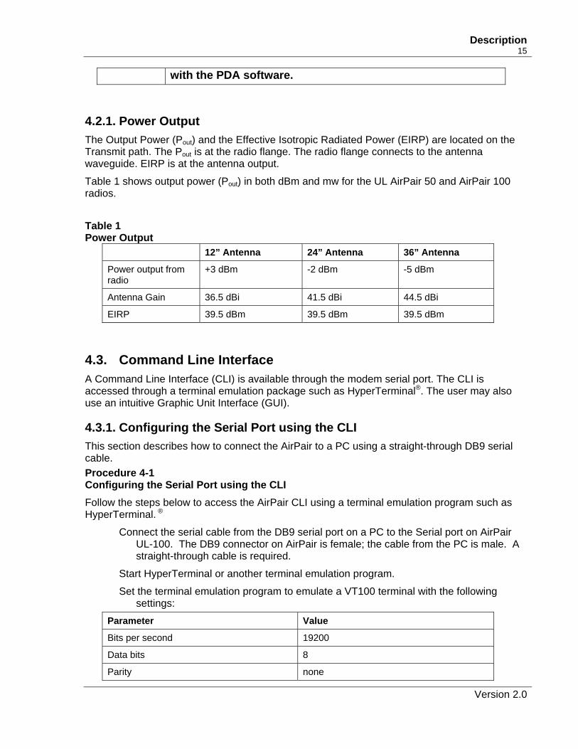
4.2.1. Power Output The Output Power (Pout) and the Effective Isotropic Radiated Power (EIRP) are located on the Transmit path. The Pout is at the radio flange. The radio flange connects to the antenna waveguide. EIRP is at the antenna output.
Table 1 shows output power (Pout) in both dBm and mw for the UL AirPair 50 and AirPair 100 radios.
Table 1 Power Output
12” Antenna 24” Antenna 36” Antenna
Power output from radio
+3 dBm -2 dBm -5 dBm
Antenna Gain 36.5 dBi 41.5 dBi 44.5 dBi
EIRP 39.5 dBm 39.5 dBm 39.5 dBm
4.3. Command Line Interface A Command Line Interface (CLI) is available through the modem serial port. The CLI is accessed through a terminal emulation package such as HyperTerminal®. The user may also use an intuitive Graphic Unit Interface (GUI).
4.3.1. Configuring the Serial Port using the CLI This section describes how to connect the AirPair to a PC using a straight-through DB9 serial cable. Procedure 4-1 Configuring the Serial Port using the CLI Follow the steps below to access the AirPair CLI using a terminal emulation program such as HyperTerminal. ®
Connect the serial cable from the DB9 serial port on a PC to the Serial port on AirPair UL-100. The DB9 connector on AirPair is female; the cable from the PC is male. A straight-through cable is required.
Start HyperTerminal or another terminal emulation program.
Set the terminal emulation program to emulate a VT100 terminal with the following settings:
Parameter Value
Bits per second 19200
Data bits 8
Parity none
Version 2.0
16 DragonWave Inc.
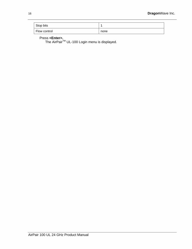
Stop bits 1
Flow control none
Press <Enter>. The AirPairTM UL-100 Login menu is displayed.
AirPair 100 UL 24 GHz Product Manual
Description 17
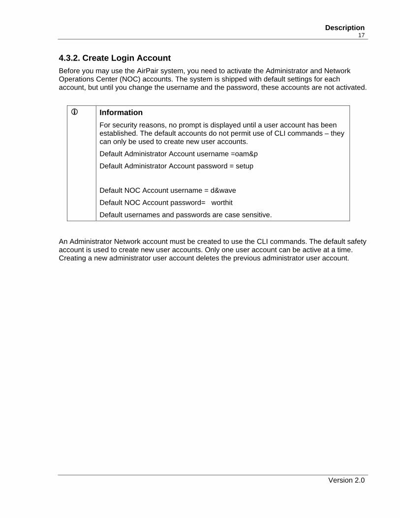
4.3.2. Create Login Account Before you may use the AirPair system, you need to activate the Administrator and Network Operations Center (NOC) accounts. The system is shipped with default settings for each account, but until you change the username and the password, these accounts are not activated.
Information For security reasons, no prompt is displayed until a user account has been established. The default accounts do not permit use of CLI commands – they can only be used to create new user accounts.
Default Administrator Account username =oam&p
Default Administrator Account password = setup
Default NOC Account username = d&wave
Default NOC Account password= worthit
Default usernames and passwords are case sensitive.
An Administrator Network account must be created to use the CLI commands. The default safety account is used to create new user accounts. Only one user account can be active at a time. Creating a new administrator user account deletes the previous administrator user account.
Version 2.0
18 DragonWave Inc.
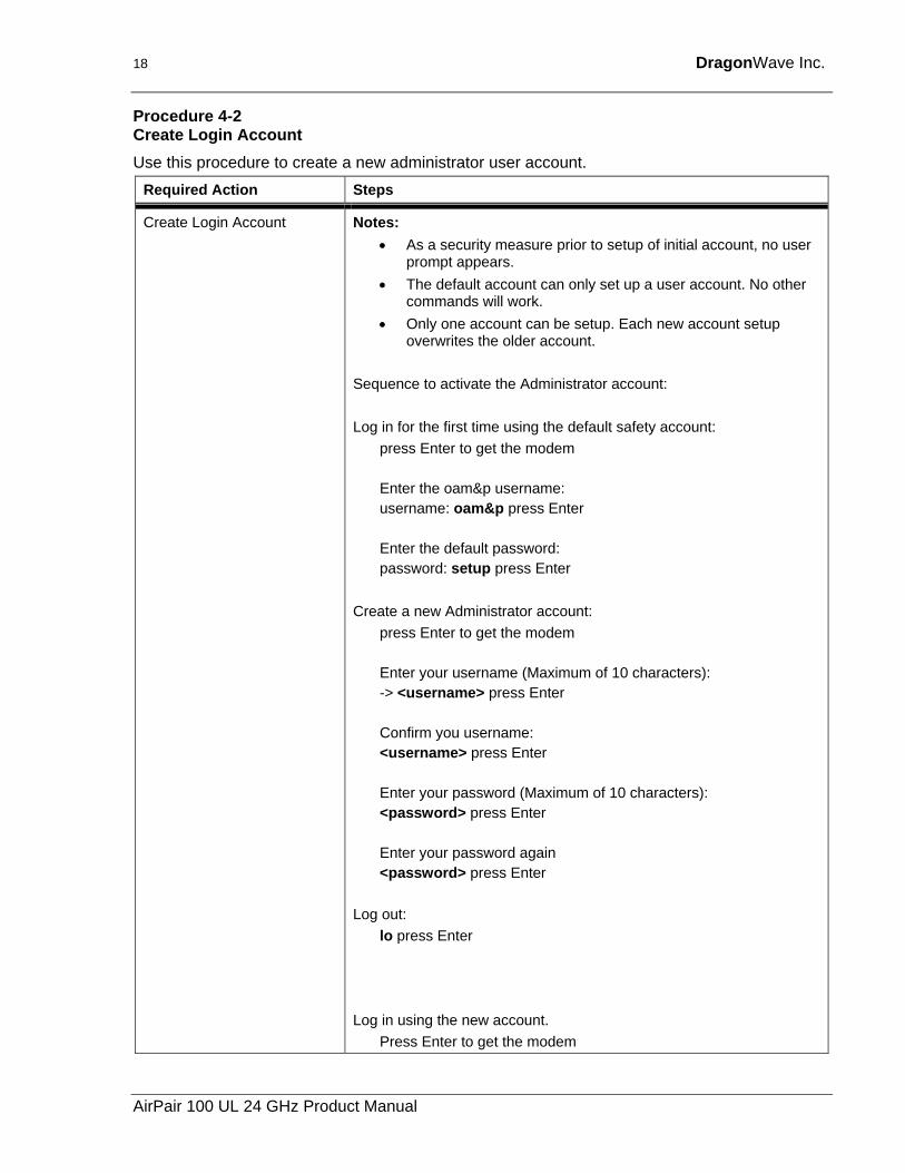
Procedure 4-2 Create Login Account Use this procedure to create a new administrator user account.
Required Action Steps
Create Login Account Notes: • As a security measure prior to setup of initial account, no user
prompt appears. • The default account can only set up a user account. No other
commands will work. • Only one account can be setup. Each new account setup
overwrites the older account. Sequence to activate the Administrator account: Log in for the first time using the default safety account:
press Enter to get the modem Enter the oam&p username: username: oam&p press Enter Enter the default password: password: setup press Enter
Create a new Administrator account:
press Enter to get the modem Enter your username (Maximum of 10 characters): -> <username> press Enter Confirm you username: <username> press Enter Enter your password (Maximum of 10 characters): <password> press Enter Enter your password again <password> press Enter
Log out: lo press Enter
Log in using the new account.
Press Enter to get the modem
AirPair 100 UL 24 GHz Product Manual
Description 19
Required Action Steps
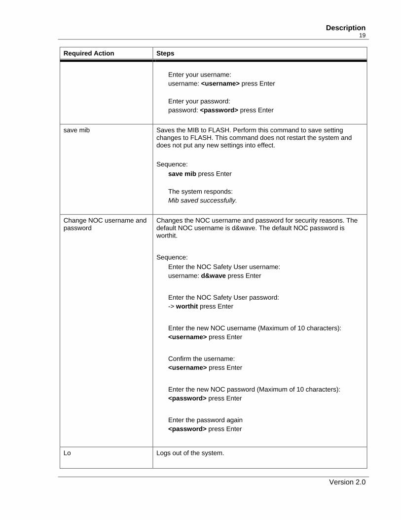
Enter your username: username: <username> press Enter Enter your password: password: <password> press Enter
save mib Saves the MIB to FLASH. Perform this command to save setting changes to FLASH. This command does not restart the system and does not put any new settings into effect. Sequence:
save mib press Enter The system responds: Mib saved successfully.
Change NOC username and password
Changes the NOC username and password for security reasons. The default NOC username is d&wave. The default NOC password is worthit.
Sequence:
Enter the NOC Safety User username: username: d&wave press Enter
Enter the NOC Safety User password: -> worthit press Enter
Enter the new NOC username (Maximum of 10 characters): <username> press Enter
Confirm the username: <username> press Enter
Enter the new NOC password (Maximum of 10 characters): <password> press Enter
Enter the password again <password> press Enter
Lo Logs out of the system.
Version 2.0
20 DragonWave Inc.
Required Action Steps
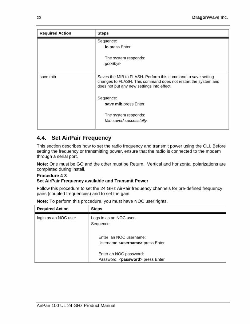
Sequence: lo press Enter The system responds: goodbye
save mib Saves the MIB to FLASH. Perform this command to save setting changes to FLASH. This command does not restart the system and does not put any new settings into effect. Sequence:
save mib press Enter The system responds: Mib saved successfully.
4.4. Set AirPair Frequency This section describes how to set the radio frequency and transmit power using the CLI. Before setting the frequency or transmitting power, ensure that the radio is connected to the modem through a serial port.
Note: One must be GO and the other must be Return. Vertical and horizontal polarizations are completed during install. Procedure 4-3 Set AirPair Frequency available and Transmit Power Follow this procedure to set the 24 GHz AirPair frequency channels for pre-defined frequency pairs (coupled frequencies) and to set the gain.
Note: To perform this procedure, you must have NOC user rights. Required Action Steps
login as an NOC user Logs in as an NOC user. Sequence:
Enter an NOC username: Username <username> press Enter Enter an NOC password: Password: <password> press Enter
AirPair 100 UL 24 GHz Product Manual
Description 21
Required Action Steps
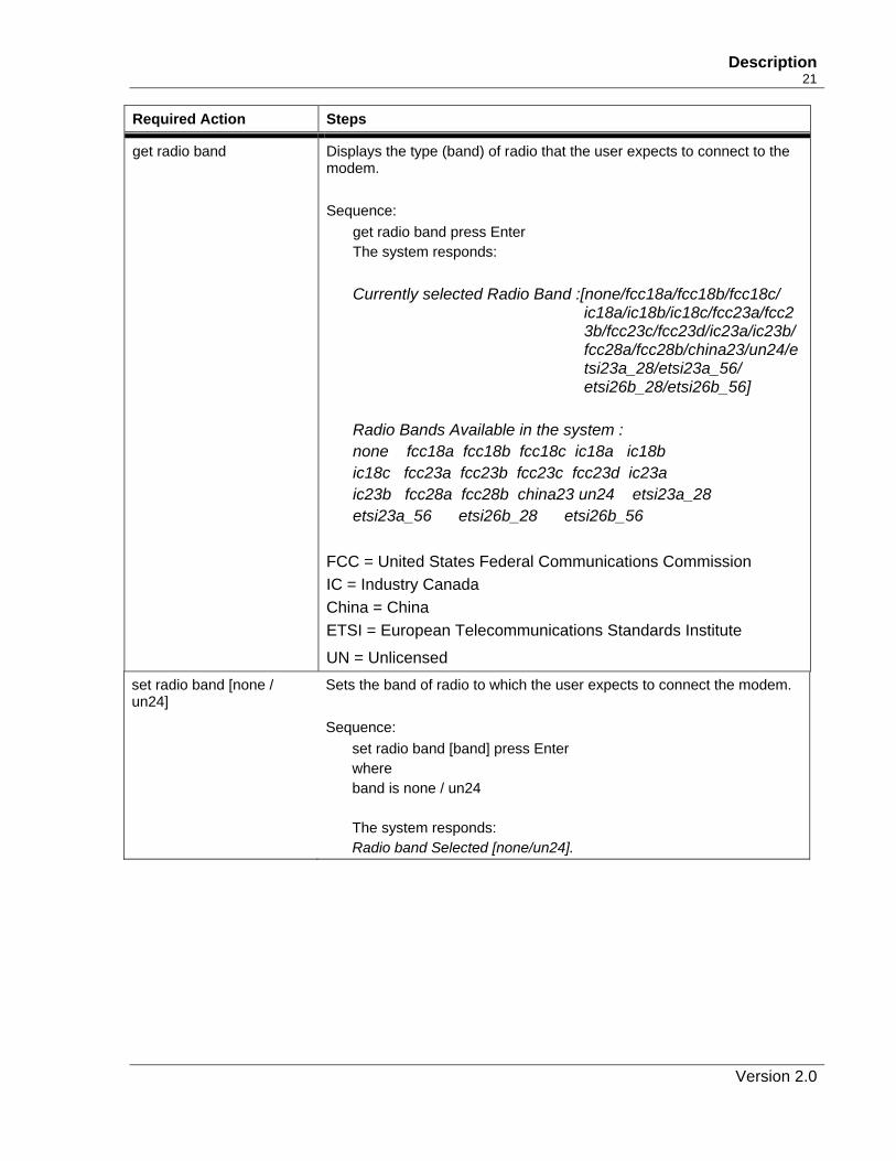
get radio band Displays the type (band) of radio that the user expects to connect to the modem. Sequence:
get radio band press Enter The system responds: Currently selected Radio Band :[none/fcc18a/fcc18b/fcc18c/
ic18a/ic18b/ic18c/fcc23a/fcc23b/fcc23c/fcc23d/ic23a/ic23b/ fcc28a/fcc28b/china23/un24/etsi23a_28/etsi23a_56/ etsi26b_28/etsi26b_56]
Radio Bands Available in the system : none fcc18a fcc18b fcc18c ic18a ic18b ic18c fcc23a fcc23b fcc23c fcc23d ic23a ic23b fcc28a fcc28b china23 un24 etsi23a_28 etsi23a_56 etsi26b_28 etsi26b_56
FCC = United States Federal Communications Commission IC = Industry Canada China = China ETSI = European Telecommunications Standards Institute
UN = Unlicensed set radio band [none / un24]
Sets the band of radio to which the user expects to connect the modem. Sequence:
set radio band [band] press Enter where band is none / un24 The system responds: Radio band Selected [none/un24].
Version 2.0
22 DragonWave Inc.
Required Action Steps
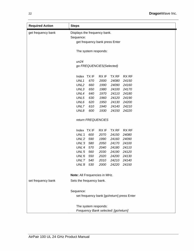
get frequency bank Displays the frequency bank. Sequence:
get frequency bank press Enter
The system responds:
un24 go FREQUENCIES(Selected)
Index TX IF RX IF TX RF RX RF UNL1 670 2000 24080 24150 UNL2 660 1990 24090 24160 UNL3 650 1980 24100 24170 UNL4 640 1970 24110 24180 UNL5 630 1960 24120 24190 UNL6 620 1950 24130 24200 UNL7 610 1940 24140 24210 UNL8 600 1930 24150 24220
return FREQUENCIES
Index TX IF RX IF TX RF RX RF UNL'1 600 2070 24150 24080 UNL'2 590 1990 24160 24090 UNL'3 580 2050 24170 24100 UNL'4 570 2040 24180 24110 UNL'5 560 2030 24190 24120 UNL'6 550 2020 24200 24130 UNL'7 540 2010 24210 24140 UNL'8 530 2000 24220 24150
Note: All Frequencies in MHz.
set frequency bank Sets the frequency bank.
Sequence:
set frequency bank [go/return] press Enter
The system responds: Frequency Bank selected: [go/return]
AirPair 100 UL 24 GHz Product Manual
Description 23
Required Action Steps
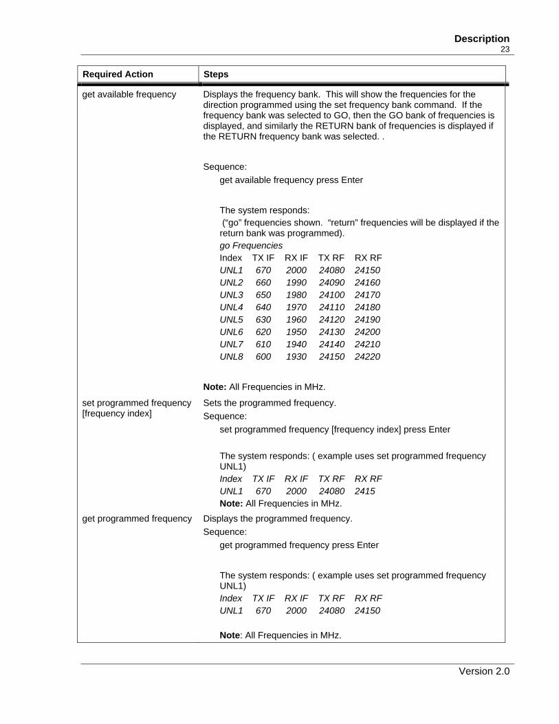
get available frequency Displays the frequency bank. This will show the frequencies for the direction programmed using the set frequency bank command. If the frequency bank was selected to GO, then the GO bank of frequencies is displayed, and similarly the RETURN bank of frequencies is displayed if the RETURN frequency bank was selected. .
Sequence:
get available frequency press Enter
The system responds: (“go” frequencies shown. “return” frequencies will be displayed if the return bank was programmed). go Frequencies Index TX IF RX IF TX RF RX RF UNL1 670 2000 24080 24150 UNL2 660 1990 24090 24160 UNL3 650 1980 24100 24170 UNL4 640 1970 24110 24180 UNL5 630 1960 24120 24190 UNL6 620 1950 24130 24200 UNL7 610 1940 24140 24210 UNL8 600 1930 24150 24220
Note: All Frequencies in MHz.
set programmed frequency [frequency index]
Sets the programmed frequency. Sequence:
set programmed frequency [frequency index] press Enter
The system responds: ( example uses set programmed frequency UNL1) Index TX IF RX IF TX RF RX RF UNL1 670 2000 24080 2415 Note: All Frequencies in MHz.
get programmed frequency Displays the programmed frequency. Sequence:
get programmed frequency press Enter
The system responds: ( example uses set programmed frequency UNL1) Index TX IF RX IF TX RF RX RF UNL1 670 2000 24080 24150 Note: All Frequencies in MHz.
Version 2.0
24 DragonWave Inc.
Required Action Steps
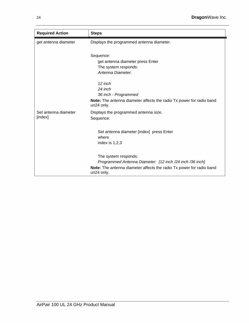
get antenna diameter Displays the programmed antenna diameter.
Sequence:
get antenna diameter press Enter The system responds: Antenna Diameter: 12 inch 24 inch 36 inch - Programmed
Note: The antenna diameter affects the radio Tx power for radio band un24 only.
Set antenna diameter [index]
Displays the programmed antenna size. Sequence:
Set antenna diameter [index] press Enter where index is 1,2,3
The system responds: Programmed Antenna Diameter: [12 inch /24 inch /36 inch]
Note: The antenna diameter affects the radio Tx power for radio band un24 only.
AirPair 100 UL 24 GHz Product Manual
Description 25
Required Action Steps
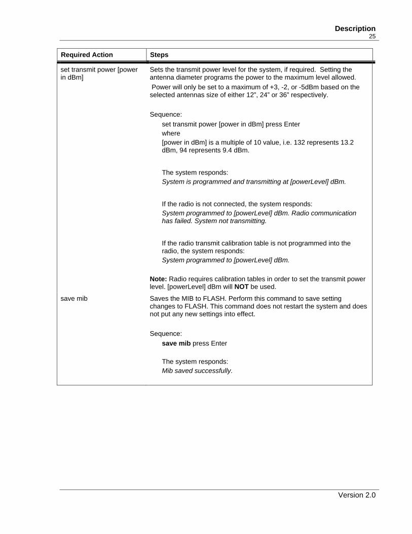
set transmit power [power in dBm]
Sets the transmit power level for the system, if required. Setting the antenna diameter programs the power to the maximum level allowed. Power will only be set to a maximum of +3, -2, or -5dBm based on the selected antennas size of either 12”, 24” or 36” respectively. Sequence:
set transmit power [power in dBm] press Enter where [power in dBm] is a multiple of 10 value, i.e. 132 represents 13.2 dBm, 94 represents 9.4 dBm.
The system responds: System is programmed and transmitting at [powerLevel] dBm.
If the radio is not connected, the system responds: System programmed to [powerLevel] dBm. Radio communication has failed. System not transmitting.
If the radio transmit calibration table is not programmed into the radio, the system responds: System programmed to [powerLevel] dBm.
Note: Radio requires calibration tables in order to set the transmit power level. [powerLevel] dBm will NOT be used.
save mib Saves the MIB to FLASH. Perform this command to save setting changes to FLASH. This command does not restart the system and does not put any new settings into effect. Sequence:
save mib press Enter The system responds: Mib saved successfully.
Version 2.0
26 DragonWave Inc.
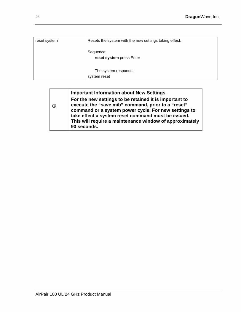
reset system Resets the system with the new settings taking effect.
Sequence:
reset system press Enter
The system responds:
system reset
Important Information about New Settings. For the new settings to be retained it is important to execute the “save mib” command, prior to a “reset” command or a system power cycle. For new settings to take effect a system reset command must be issued. This will require a maintenance window of approximately 90 seconds.
AirPair 100 UL 24 GHz Product Manual
Description 27
4.5. Set IP address You can use Telnet to access the AirPair system from your PC using an Internet Protocol (IP) address. An IP address is a number given to a device so that a network can identify it. The IP address format is a 32-bit numeric address written as four numbers separated by periods. For example, 192.168.0.1 could be an IP address. If you assign an IP address to your modem, you can access the modem from your network.
Version 2.0
28 DragonWave Inc.
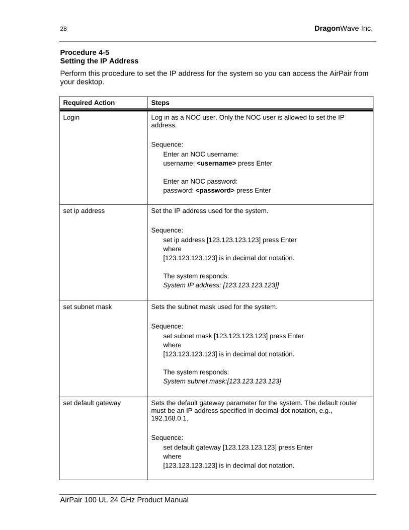
Procedure 4-5 Setting the IP Address Perform this procedure to set the IP address for the system so you can access the AirPair from your desktop. Required Action Steps
Login Log in as a NOC user. Only the NOC user is allowed to set the IP address. Sequence:
Enter an NOC username: username: <username> press Enter Enter an NOC password: password: <password> press Enter
set ip address Set the IP address used for the system. Sequence:
set ip address [123.123.123.123] press Enter where [123.123.123.123] is in decimal dot notation. The system responds: System IP address: [123.123.123.123]]
set subnet mask
Sets the subnet mask used for the system. Sequence:
set subnet mask [123.123.123.123] press Enter where [123.123.123.123] is in decimal dot notation. The system responds: System subnet mask:[123.123.123.123]
set default gateway Sets the default gateway parameter for the system. The default router must be an IP address specified in decimal-dot notation, e.g., 192.168.0.1. Sequence:
set default gateway [123.123.123.123] press Enter where [123.123.123.123] is in decimal dot notation.
AirPair 100 UL 24 GHz Product Manual
Description 29
Required Action Steps
The system responds: NAK’ if request cannot be processed, otherwise returns the following which acknowledges completion of the request: System default gateway: 123.123.123.123
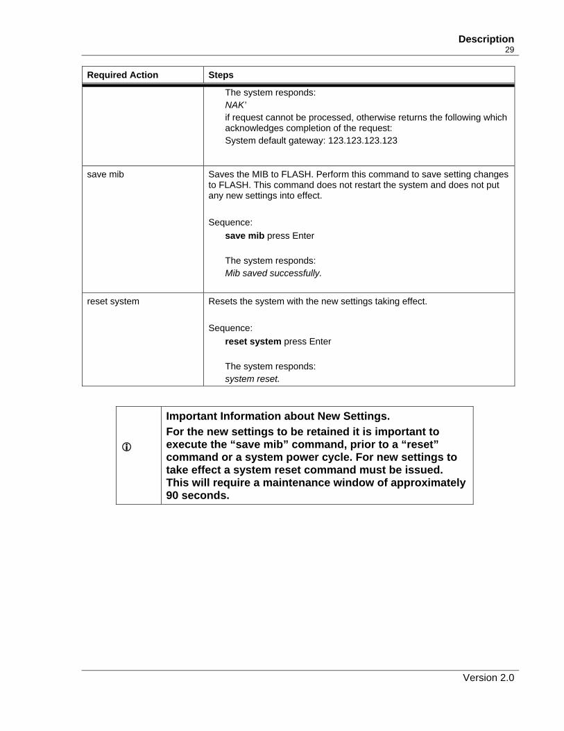
save mib Saves the MIB to FLASH. Perform this command to save setting changes
to FLASH. This command does not restart the system and does not put any new settings into effect. Sequence:
save mib press Enter The system responds: Mib saved successfully.
reset system Resets the system with the new settings taking effect. Sequence:
reset system press Enter The system responds: system reset.
Important Information about New Settings. For the new settings to be retained it is important to execute the “save mib” command, prior to a “reset” command or a system power cycle. For new settings to take effect a system reset command must be issued. This will require a maintenance window of approximately 90 seconds.
Version 2.0
30 DragonWave Inc.
4.6. VLAN tagging A Local Area Network (LAN) is a single-broadcast domain. If a user broadcasts information on the LAN, every other user on the LAN receives the broadcast. A router prevents broadcast messages from leaving a LAN, which reduces collisions and improves performance.
A network manager can create smaller broadcast domains and reduce network broadcasts by logically segmenting a LAN into different broadcast domains. These broadcast domains are called Virtual Local Area Networks (VLANs). Workstations on a VLAN do not have to be located together because they are segmented logically, not physically.
VLANs offer a number of advantages over traditional LANs including:
• Performance
• Security
• formation of virtual workgroups
• cost reduction
All ports on a switch are configured for a default VLAN (usually VLAN1). When a switch receives data from a workstation, it tags the data with a VLAN identifier indicating the originating VLAN. The switch sends the data to the ports inside the VLAN where it originated. It also sends the data to a trunking port if one is available.
Network Administrators create VLAN groups and place backbone network devices into the VLAN group to simplify administration and increase security of the devices. VLAN tagging allows network administrators to add AirPair nodes to the administrative network. VLAN tagging restricts administrative access to devices that are members of the VLAN group.
If you program an AirPair node with an IP address but do not enable VLAN tagging, the node responds to Ping, Telnet and SNMP commands from any device on the network. Telnet and SNMP require a username and password, the proper IP address and community string, respectively.
If you enable VLAN tagging, the AirPair nodes respond to ping commands but do not respond to Telnet and SNMP commands unless the packet has the correct VLAN tag. The Telnet and SNMP requests must have the correct VLAN tag and come from a device within the VLAN domain.
The Institute of Electrical and Electronic Engineers (IEEE) is working on a draft standard 802.1Q for VLANs. Currently, most products are proprietary and anyone wanting to install VLANs has to purchase all products from the same vendor. DragonWave implements AirPair VLAN Tagging using the 802.1Q standard. For more information on the Standard, see the web page:
http://grouper.ieee.org/groups/802/1/pages/802.1Q.html
AirPair 100 UL 24 GHz Product Manual
Description 31
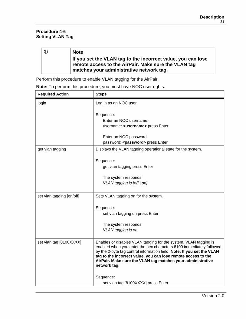
Procedure 4-6 Setting VLAN Tag
Note If you set the VLAN tag to the incorrect value, you can lose remote access to the AirPair. Make sure the VLAN tag matches your administrative network tag.
Perform this procedure to enable VLAN tagging for the AirPair.
Note: To perform this procedure, you must have NOC user rights. Required Action Steps
login Log in as an NOC user. Sequence:
Enter an NOC username: username: <username> press Enter Enter an NOC password: password: <password> press Enter
get vlan tagging Displays the VLAN tagging operational state for the system. Sequence:
get vlan tagging press Enter The system responds: VLAN tagging is [off | on]
set vlan tagging [on/off] Sets VLAN tagging on for the system. Sequence:
set vlan tagging on press Enter The system responds: VLAN tagging is on.
set vlan tag [8100XXXX] Enables or disables VLAN tagging for the system. VLAN tagging is enabled when you enter the hex characters 8100 immediately followed by the 2-byte tag control information field. Note: If you set the VLAN tag to the incorrect value, you can lose remote access to the AirPair. Make sure the VLAN tag matches your administrative network tag. Sequence:
set vlan tag [8100XXXX] press Enter
Version 2.0
32 DragonWave Inc.
Required Action Steps
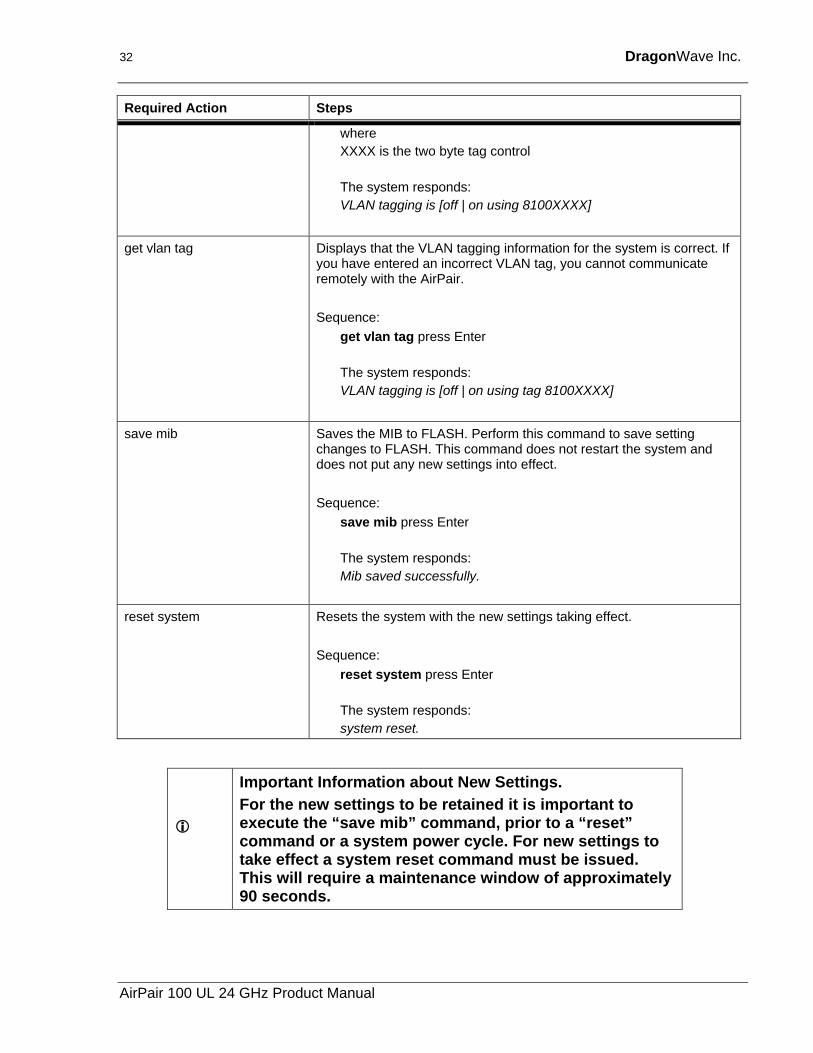
where XXXX is the two byte tag control The system responds: VLAN tagging is [off | on using 8100XXXX]
get vlan tag Displays that the VLAN tagging information for the system is correct. If you have entered an incorrect VLAN tag, you cannot communicate remotely with the AirPair. Sequence:
get vlan tag press Enter The system responds: VLAN tagging is [off | on using tag 8100XXXX]
save mib Saves the MIB to FLASH. Perform this command to save setting changes to FLASH. This command does not restart the system and does not put any new settings into effect. Sequence:
save mib press Enter The system responds: Mib saved successfully.
reset system Resets the system with the new settings taking effect. Sequence:
reset system press Enter The system responds: system reset.
Important Information about New Settings. For the new settings to be retained it is important to execute the “save mib” command, prior to a “reset” command or a system power cycle. For new settings to take effect a system reset command must be issued. This will require a maintenance window of approximately 90 seconds.
AirPair 100 UL 24 GHz Product Manual
5. Installation This section describes how to install the DragonWave AirPair. Perform the procedures in this section in sequence presented.
5.1. Before you begin Caution
DragonWave Inc. recommends to connect the AirPair system to an Uninterruptable Power Supply (UPS) or an equivalent system in order to withstand power interruptions. Before installation, preset each DragonWave radio to the desired channel within the frequency band allocated to this particular installation.
5.2. Mounting Specifications Caution
The mounting poles must be capable of providing sufficient stability.
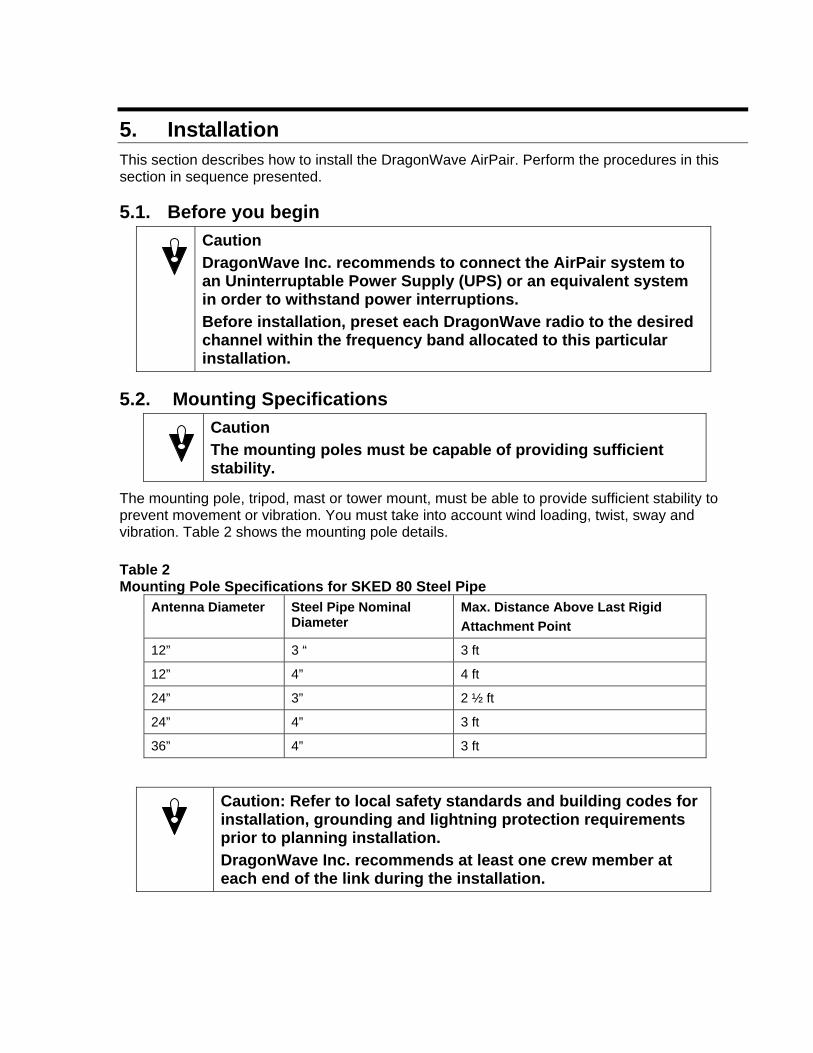
The mounting pole, tripod, mast or tower mount, must be able to provide sufficient stability to prevent movement or vibration. You must take into account wind loading, twist, sway and vibration. Table 2 shows the mounting pole details. Table 2 Mounting Pole Specifications for SKED 80 Steel Pipe
Antenna Diameter Steel Pipe Nominal Diameter
Max. Distance Above Last Rigid Attachment Point
12” 3 “ 3 ft
12” 4” 4 ft
24” 3” 2 ½ ft
24” 4” 3 ft
36” 4” 3 ft
Caution: Refer to local safety standards and building codes for installation, grounding and lightning protection requirements prior to planning installation. DragonWave Inc. recommends at least one crew member at each end of the link during the installation.

34 DragonWave Inc.
This page is intentionally left blank.
AirPair 100 UL 24 GHz Product Manual
6. Installation of Radio and Modem This section describes how to install the radio and modem. The steps in the installation are:
• install mounting bracket onto mast or tower
• mount the radio and antenna onto the mounting bracket
• perform visual alignment of radio
• attach modem onto mounting bracket
• connect the low-loss RF cable and the RS-232 cable between the modem and the radio
• install grounding and lightning protection
• connect power to the modem by connecting the power cable between the power pack and the modem
• perform fine-adjust alignment of the radios using the PDA
• perform data test
• connect the LAN to the modem
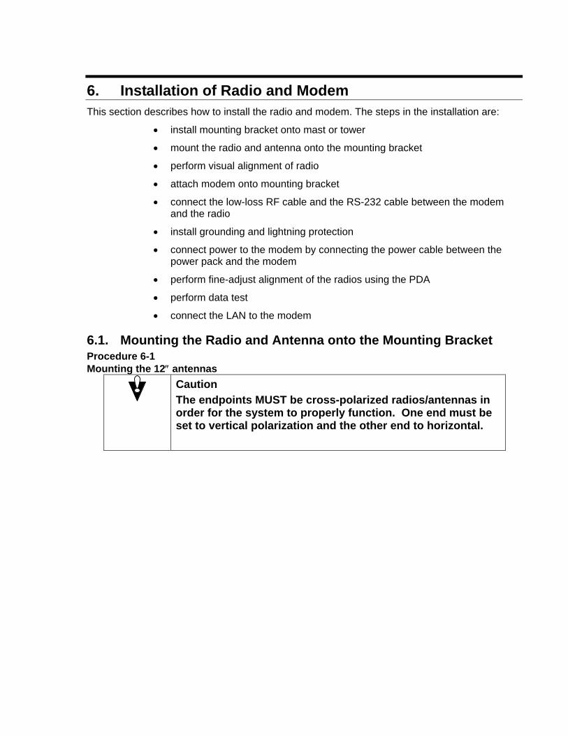
6.1. Mounting the Radio and Antenna onto the Mounting Bracket Procedure 6-1 Mounting the 12″ antennas
Caution The endpoints MUST be cross-polarized radios/antennas in order for the system to properly function. One end must be set to vertical polarization and the other end to horizontal.
36 DragonWave Inc.
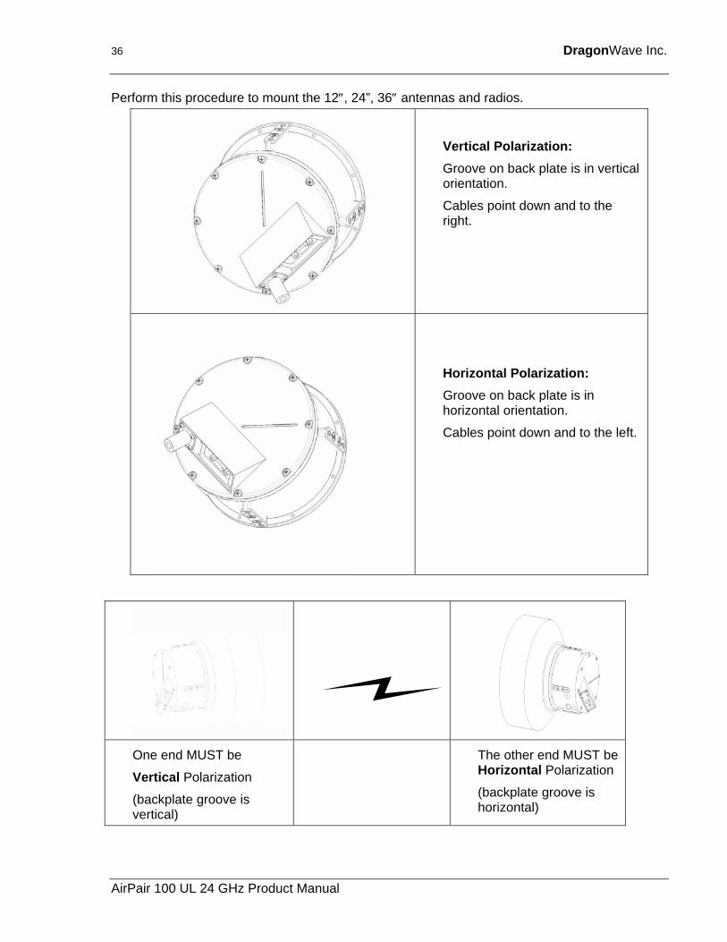
Perform this procedure to mount the 12″, 24”, 36″ antennas and radios.
Vertical Polarization: Groove on back plate is in vertical orientation.
Cables point down and to the right.
Horizontal Polarization: Groove on back plate is in horizontal orientation.
Cables point down and to the left.
One end MUST be
Vertical Polarization
(backplate groove is vertical)
The other end MUST be Horizontal Polarization
(backplate groove is horizontal)
AirPair 100 UL 24 GHz Product Manual
Installation of Radio and Modem 37
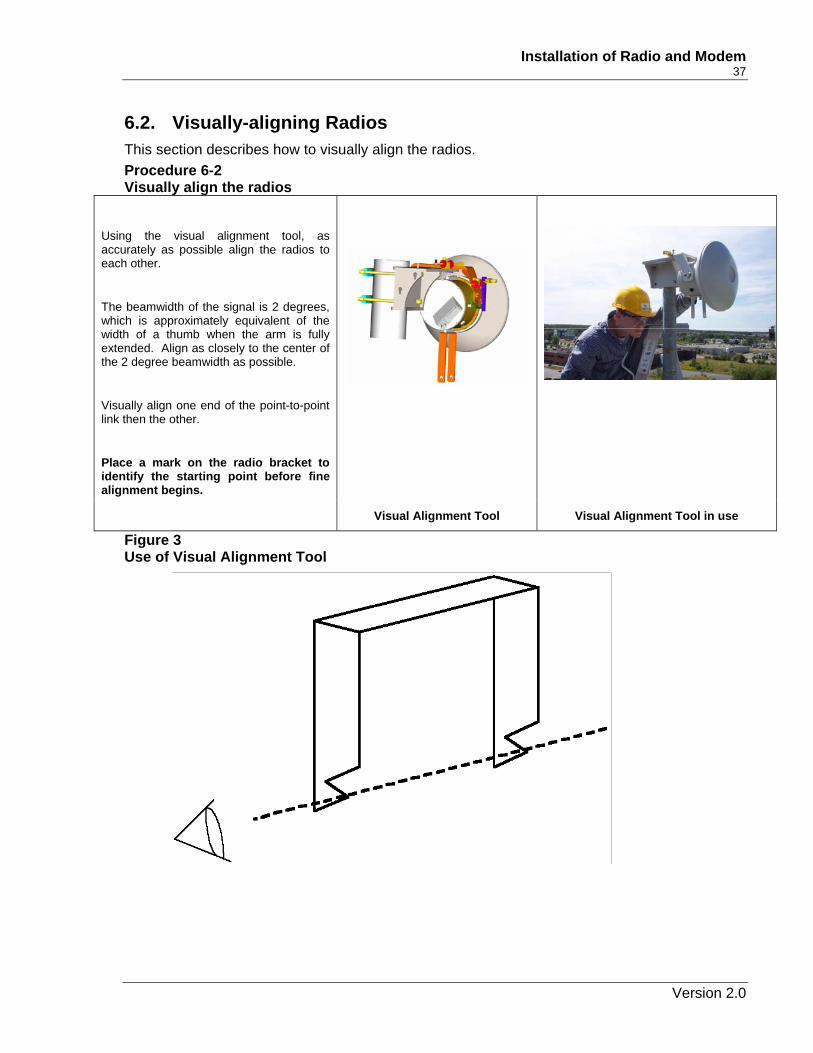
6.2. Visually-aligning Radios This section describes how to visually align the radios. Procedure 6-2 Visually align the radios
Figure 3 Use of Visual Alignment Tool
Using the visual alignment tool, as accurately as possible align the radios to each other.
The beamwidth of the signal is 2 degrees, which is approximately equivalent of the width of a thumb when the arm is fully extended. Align as closely to the center of the 2 degree beamwidth as possible.
Visually align one end of the point-to-point link then the other.
Place a mark on the radio bracket to identify the starting point before fine alignment begins.
Visual Alignment Tool Visual Alignment Tool in use
Version 2.0
38 DragonWave Inc.
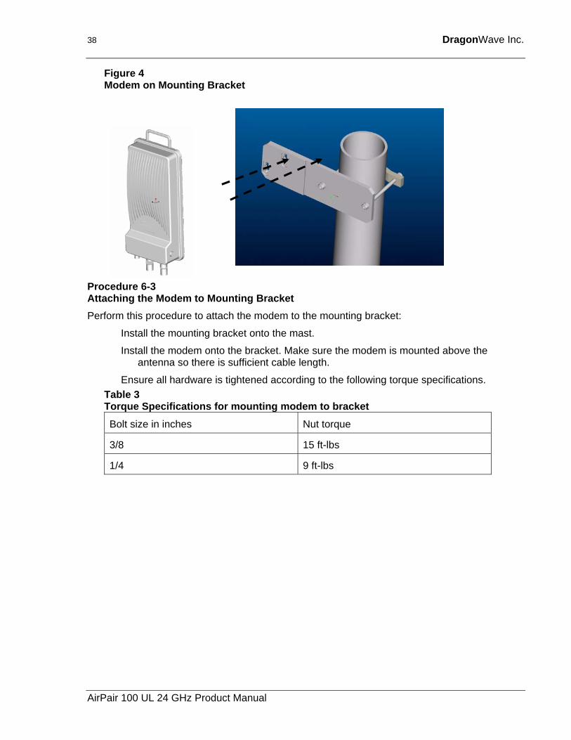
Figure 4 Modem on Mounting Bracket
Procedure 6-3 Attaching the Modem to Mounting Bracket Perform this procedure to attach the modem to the mounting bracket:
Install the mounting bracket onto the mast.
Install the modem onto the bracket. Make sure the modem is mounted above the antenna so there is sufficient cable length.
Ensure all hardware is tightened according to the following torque specifications. Table 3 Torque Specifications for mounting modem to bracket Bolt size in inches Nut torque
3/8 15 ft-lbs
1/4 9 ft-lbs
AirPair 100 UL 24 GHz Product Manual
Installation of Radio and Modem 39
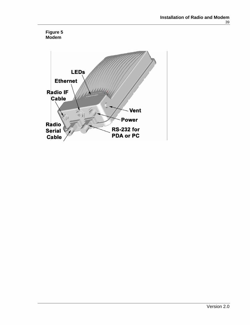
Figure 5 Modem
Version 2.0
40 DragonWave Inc.
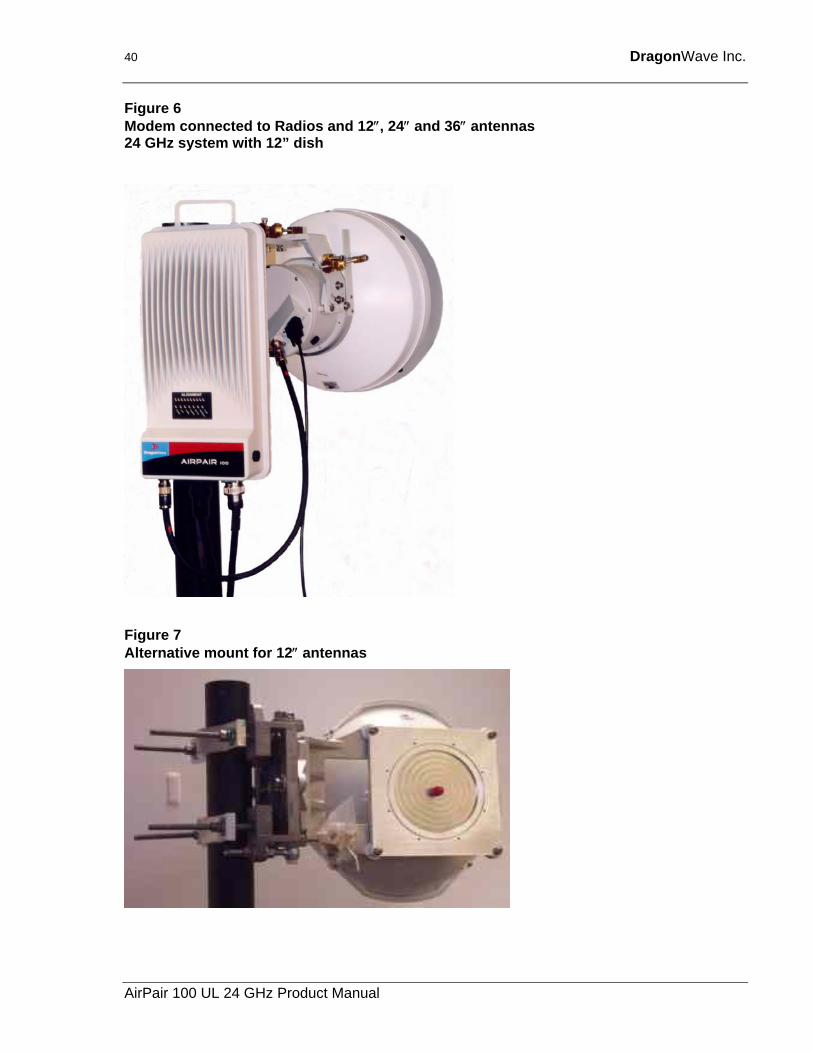
Figure 6 Modem connected to Radios and 12″, 24″ and 36″ antennas 24 GHz system with 12” dish
Figure 7 Alternative mount for 12″ antennas
AirPair 100 UL 24 GHz Product Manual
Installation of Radio and Modem 41
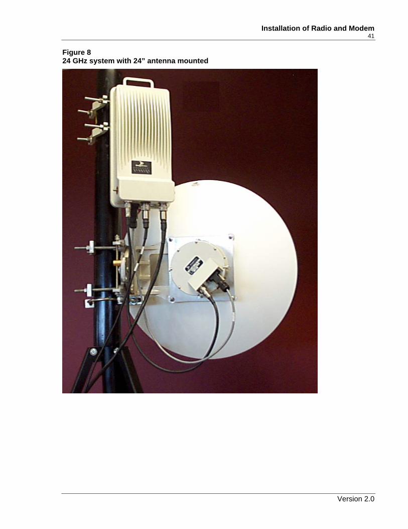
Figure 8 24 GHz system with 24” antenna mounted
Version 2.0
42 DragonWave Inc.
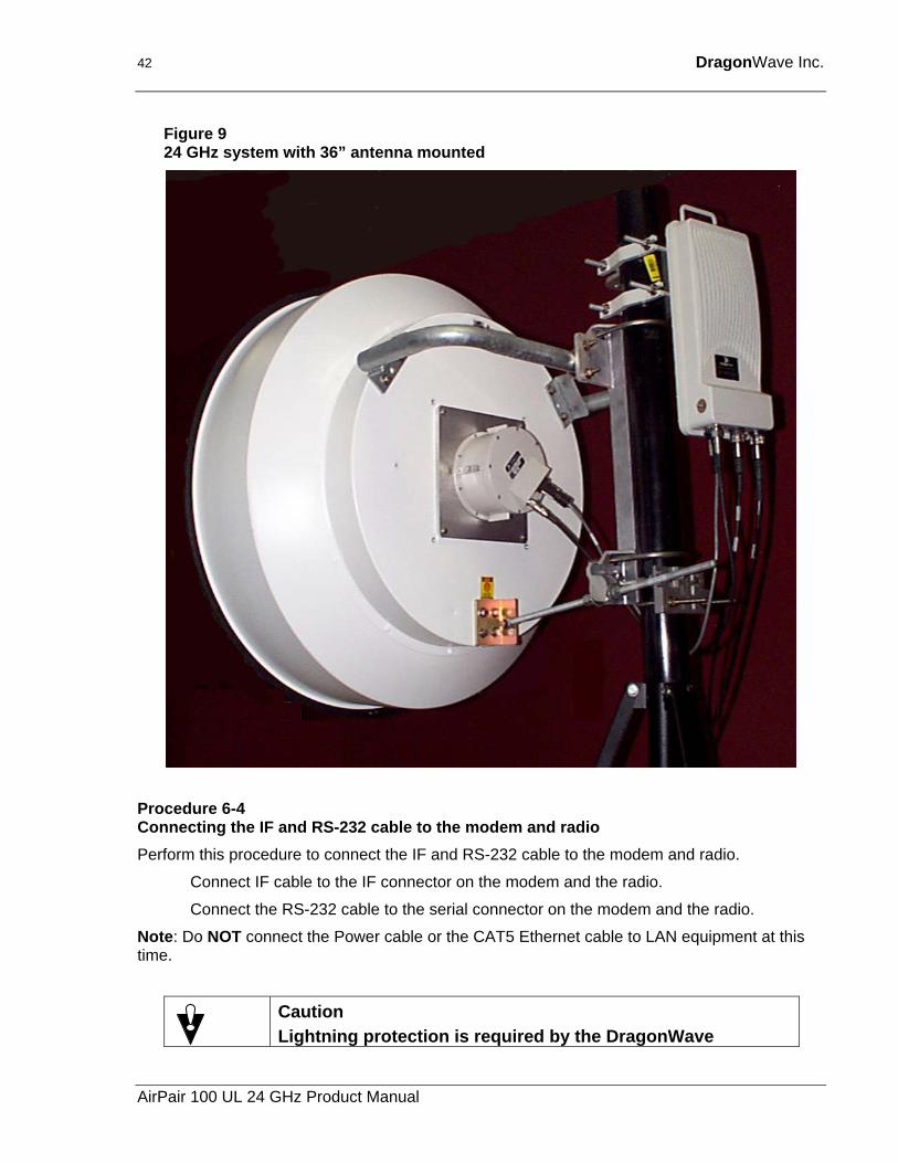
Figure 9 24 GHz system with 36” antenna mounted
Procedure 6-4 Connecting the IF and RS-232 cable to the modem and radio Perform this procedure to connect the IF and RS-232 cable to the modem and radio.
Connect IF cable to the IF connector on the modem and the radio.
Connect the RS-232 cable to the serial connector on the modem and the radio.
Note: Do NOT connect the Power cable or the CAT5 Ethernet cable to LAN equipment at this time.
Caution Lightning protection is required by the DragonWave
AirPair 100 UL 24 GHz Product Manual
Installation of Radio and Modem 43
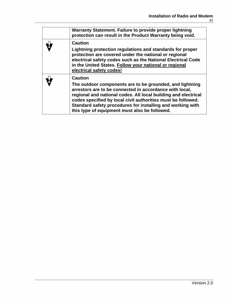
Warranty Statement. Failure to provide proper lightning protection can result in the Product Warranty being void.
Caution Lightning protection regulations and standards for proper protection are covered under the national or regional electrical safety codes such as the National Electrical Code in the United States. Follow your national or regional electrical safety codes!
Caution The outdoor components are to be grounded, and lightning arrestors are to be connected in accordance with local, regional and national codes. All local building and electrical codes specified by local civil authorities must be followed. Standard safety procedures for installing and working with this type of equipment must also be followed.
Version 2.0
44 DragonWave Inc.
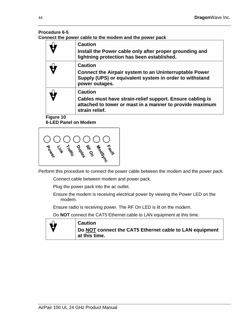
Procedure 6-5 Connect the power cable to the modem and the power pack
Caution Install the Power cable only after proper grounding and lightning protection has been established.
Caution Connect the Airpair system to an Uninterruptable Power Supply (UPS) or equivalent system in order to withstand power outages.
Caution Cables must have strain-relief support. Ensure cabling is attached to tower or mast in a manner to provide maximum strain relief.
Figure 10 6-LED Panel on Modem
Perform this procedure to connect the power cable between the modem and the power pack.
Connect cable between modem and power pack.
Plug the power pack into the ac outlet.
Ensure the modem is receiving electrical power by viewing the Power LED on the modem.
Ensure radio is receiving power. The RF On LED is lit on the modem.
Do NOT connect the CAT5 Ethernet cable to LAN equipment at this time.
Caution Do NOT connect the CAT5 Ethernet cable to LAN equipment at this time.
AirPair 100 UL 24 GHz Product Manual
Installation of Radio and Modem 45
6.3. Fine-adjust alignment of the radios This section describes how to perform fine-adjust alignment of the radios. When you prepare to align the radios, you must consider two important factors:
• Main Lobe and Side Lobes of Radio Waves
• Clear Line of Sight (LOS)
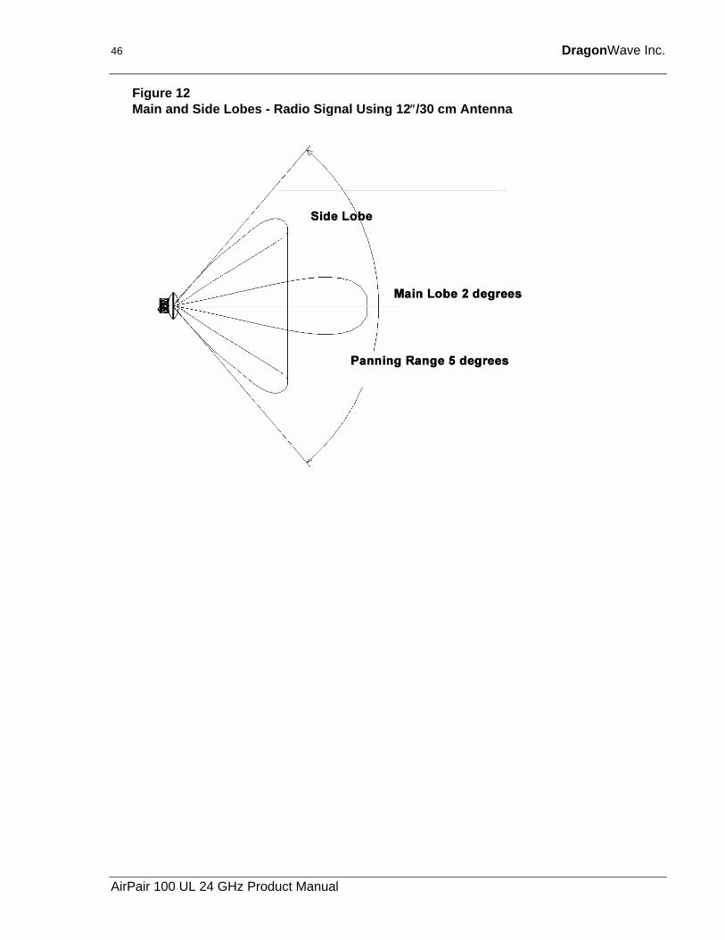
6.3.1. Main Lobe and Side Lobes of Radio Waves When you align the radios, make sure you align to the Main Lobe of the transmission. If you mistake a Main Lobe for a Side Lobe during installation, there can be a 20-30 dB loss of signal strength. For example, if the Calculated RSSI = -42 dB then the side lobe would be at approximately -62 dB, or 20 dB lower than the calculated level.
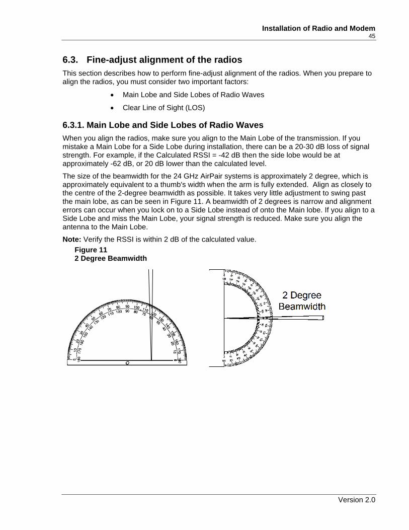
The size of the beamwidth for the 24 GHz AirPair systems is approximately 2 degree, which is approximately equivalent to a thumb's width when the arm is fully extended. Align as closely to the centre of the 2-degree beamwidth as possible. It takes very little adjustment to swing past the main lobe, as can be seen in Figure 11. A beamwidth of 2 degrees is narrow and alignment errors can occur when you lock on to a Side Lobe instead of onto the Main lobe. If you align to a Side Lobe and miss the Main Lobe, your signal strength is reduced. Make sure you align the antenna to the Main Lobe.
Note: Verify the RSSI is within 2 dB of the calculated value. Figure 11 2 Degree Beamwidth
Version 2.0
46 DragonWave Inc.
Figure 12 Main and Side Lobes - Radio Signal Using 12″/30 cm Antenna
AirPair 100 UL 24 GHz Product Manual
Installation of Radio and Modem 47
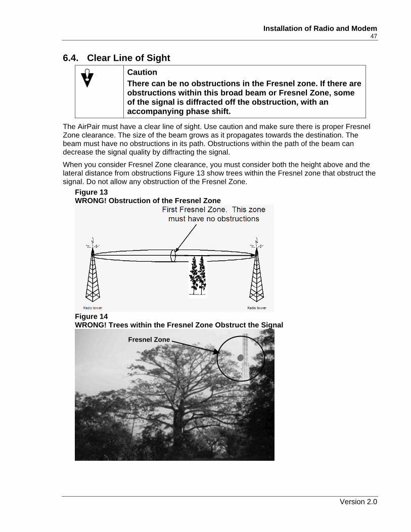
6.4. Clear Line of Sight Caution
There can be no obstructions in the Fresnel zone. If there are obstructions within this broad beam or Fresnel Zone, some of the signal is diffracted off the obstruction, with an accompanying phase shift.
The AirPair must have a clear line of sight. Use caution and make sure there is proper Fresnel Zone clearance. The size of the beam grows as it propagates towards the destination. The beam must have no obstructions in its path. Obstructions within the path of the beam can decrease the signal quality by diffracting the signal.
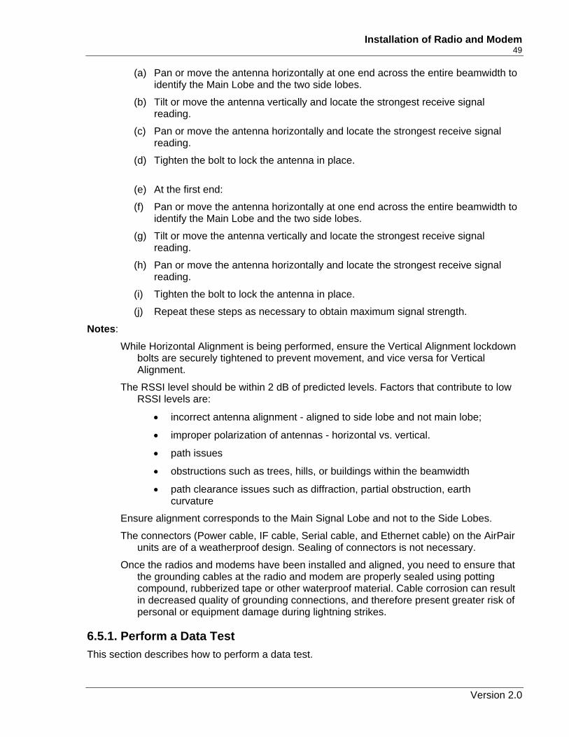
When you consider Fresnel Zone clearance, you must consider both the height above and the lateral distance from obstructions Figure 13 show trees within the Fresnel zone that obstruct the signal. Do not allow any obstruction of the Fresnel Zone.
Figure 13 WRONG! Obstruction of the Fresnel Zone
Figure 14 WRONG! Trees within the Fresnel Zone Obstruct the Signal
Fresnel Zone
Version 2.0
48 DragonWave Inc.
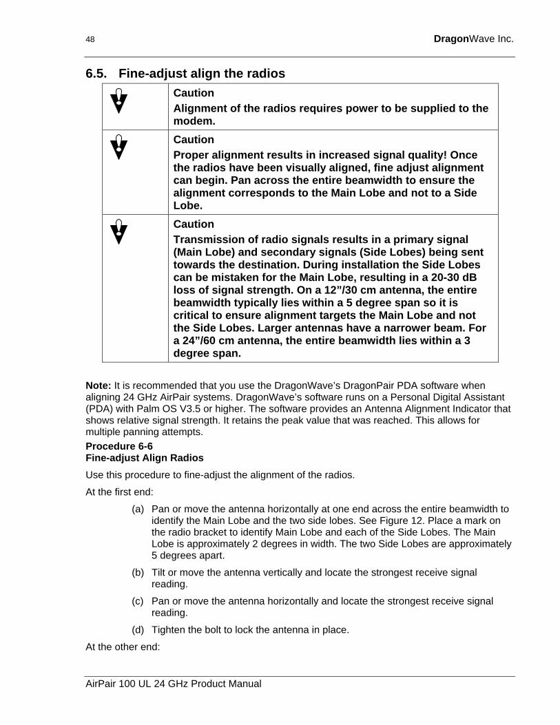
6.5. Fine-adjust align the radios Caution
Alignment of the radios requires power to be supplied to the modem.
Caution Proper alignment results in increased signal quality! Once the radios have been visually aligned, fine adjust alignment can begin. Pan across the entire beamwidth to ensure the alignment corresponds to the Main Lobe and not to a Side Lobe.
Caution Transmission of radio signals results in a primary signal (Main Lobe) and secondary signals (Side Lobes) being sent towards the destination. During installation the Side Lobes can be mistaken for the Main Lobe, resulting in a 20-30 dB loss of signal strength. On a 12”/30 cm antenna, the entire beamwidth typically lies within a 5 degree span so it is critical to ensure alignment targets the Main Lobe and not the Side Lobes. Larger antennas have a narrower beam. For a 24”/60 cm antenna, the entire beamwidth lies within a 3 degree span.
Note: It is recommended that you use the DragonWave’s DragonPair PDA software when aligning 24 GHz AirPair systems. DragonWave’s software runs on a Personal Digital Assistant (PDA) with Palm OS V3.5 or higher. The software provides an Antenna Alignment Indicator that shows relative signal strength. It retains the peak value that was reached. This allows for multiple panning attempts. Procedure 6-6 Fine-adjust Align Radios Use this procedure to fine-adjust the alignment of the radios.
At the first end:
(a) Pan or move the antenna horizontally at one end across the entire beamwidth to identify the Main Lobe and the two side lobes. See Figure 12. Place a mark on the radio bracket to identify Main Lobe and each of the Side Lobes. The Main Lobe is approximately 2 degrees in width. The two Side Lobes are approximately 5 degrees apart.
(b) Tilt or move the antenna vertically and locate the strongest receive signal reading.
(c) Pan or move the antenna horizontally and locate the strongest receive signal reading.
(d) Tighten the bolt to lock the antenna in place.
At the other end:
AirPair 100 UL 24 GHz Product Manual
Installation of Radio and Modem 49
(a) Pan or move the antenna horizontally at one end across the entire beamwidth to identify the Main Lobe and the two side lobes.
(b) Tilt or move the antenna vertically and locate the strongest receive signal reading.
(c) Pan or move the antenna horizontally and locate the strongest receive signal reading.
(d) Tighten the bolt to lock the antenna in place.
(e) At the first end:
(f) Pan or move the antenna horizontally at one end across the entire beamwidth to identify the Main Lobe and the two side lobes.
(g) Tilt or move the antenna vertically and locate the strongest receive signal reading.
(h) Pan or move the antenna horizontally and locate the strongest receive signal reading.
(i) Tighten the bolt to lock the antenna in place.
(j) Repeat these steps as necessary to obtain maximum signal strength.
Notes:
While Horizontal Alignment is being performed, ensure the Vertical Alignment lockdown bolts are securely tightened to prevent movement, and vice versa for Vertical Alignment.
The RSSI level should be within 2 dB of predicted levels. Factors that contribute to low RSSI levels are:
• incorrect antenna alignment - aligned to side lobe and not main lobe;
• improper polarization of antennas - horizontal vs. vertical.
• path issues
• obstructions such as trees, hills, or buildings within the beamwidth
• path clearance issues such as diffraction, partial obstruction, earth curvature
Ensure alignment corresponds to the Main Signal Lobe and not to the Side Lobes.
The connectors (Power cable, IF cable, Serial cable, and Ethernet cable) on the AirPair units are of a weatherproof design. Sealing of connectors is not necessary.
Once the radios and modems have been installed and aligned, you need to ensure that the grounding cables at the radio and modem are properly sealed using potting compound, rubberized tape or other waterproof material. Cable corrosion can result in decreased quality of grounding connections, and therefore present greater risk of personal or equipment damage during lightning strikes.
6.5.1. Perform a Data Test This section describes how to perform a data test.
Version 2.0
50 DragonWave Inc.
Procedure 6-7 Perform a data test Perform this procedure to confirm the network link is working properly. It is assumed that you are using an Ethernet traffic-generating device.
Connect the device to the Ethernet cable at either end.
Confirm data can be passed within desired error rates. This will ensure the network link is working in a satisfactory manner prior to running applications over the link.
6.5.2. Connect to the LAN This section describes how to connect the system to the LAN with an Ethernet cable.
Caution The Ethernet Cable is meant to be connected to a Server and therefore the signal pairs on the cable must be switched in order to connect to a router or a switch.
Once alignment, sealing of cables and data test have been completed, connect the Ethernet cable to your network device.
Ensure optimum throughput. The Ethernet connection to the modem is intended to operate at 100 Mbps Full Duplex for AirPair 100 and at 50 Mbps Full Duplex for AirPair 50.
AirPair 100 UL 24 GHz Product Manual
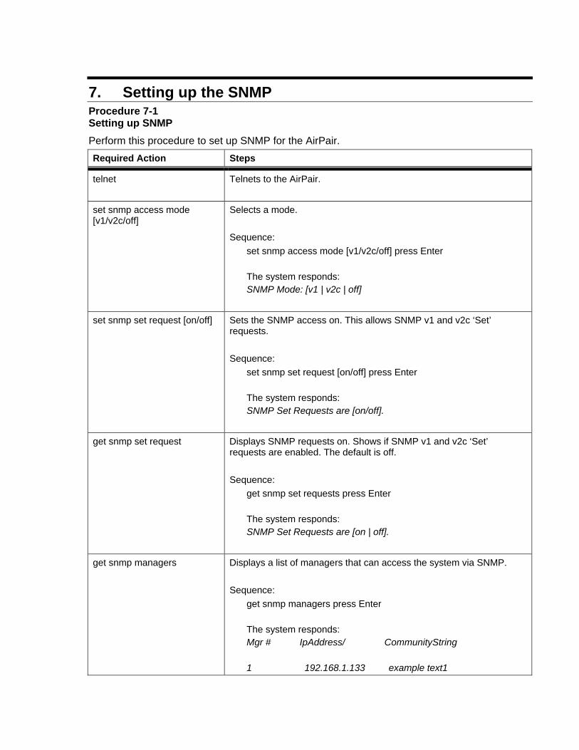
7. Setting up the SNMP Procedure 7-1 Setting up SNMP Perform this procedure to set up SNMP for the AirPair. Required Action Steps
telnet Telnets to the AirPair.
set snmp access mode [v1/v2c/off]
Selects a mode. Sequence:
set snmp access mode [v1/v2c/off] press Enter The system responds: SNMP Mode: [v1 | v2c | off]
set snmp set request [on/off] Sets the SNMP access on. This allows SNMP v1 and v2c ‘Set’ requests. Sequence:
set snmp set request [on/off] press Enter The system responds: SNMP Set Requests are [on/off].
get snmp set request Displays SNMP requests on. Shows if SNMP v1 and v2c ‘Set’ requests are enabled. The default is off. Sequence:
get snmp set requests press Enter The system responds: SNMP Set Requests are [on | off].
get snmp managers Displays a list of managers that can access the system via SNMP. Sequence:
get snmp managers press Enter The system responds: Mgr # IpAddress/ CommunityString 1 192.168.1.133 example text1
52 DragonWave Inc.
Required Action Steps
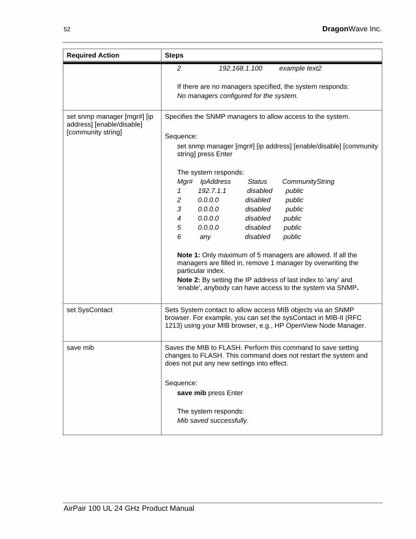
2 192.168.1.100 example text2 If there are no managers specified, the system responds: No managers configured for the system.
set snmp manager [mgr#] [ip address] [enable/disable] [community string]
Specifies the SNMP managers to allow access to the system. Sequence:
set snmp manager [mgr#] [ip address] [enable/disable] [community string] press Enter The system responds: Mgr# IpAddress Status CommunityString 1 192.7.1.1 disabled public 2 0.0.0.0 disabled public 3 0.0.0.0 disabled public 4 0.0.0.0 disabled public 5 0.0.0.0 disabled public 6 any disabled public Note 1: Only maximum of 5 managers are allowed. If all the managers are filled in, remove 1 manager by overwriting the particular index. Note 2: By setting the IP address of last index to 'any' and 'enable', anybody can have access to the system via SNMP.
set SysContact Sets System contact to allow access MIB objects via an SNMP browser. For example, you can set the sysContact in MIB-II (RFC 1213) using your MIB browser, e.g., HP OpenView Node Manager.
save mib Saves the MIB to FLASH. Perform this command to save setting changes to FLASH. This command does not restart the system and does not put any new settings into effect. Sequence:
save mib press Enter The system responds: Mib saved successfully.
AirPair 100 UL 24 GHz Product Manual
Setting up the SNMP 53
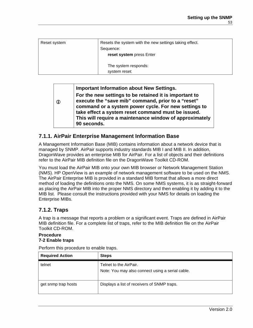
Reset system Resets the system with the new settings taking effect.
Sequence: reset system press Enter The system responds: system reset.
Important Information about New Settings. For the new settings to be retained it is important to execute the “save mib” command, prior to a “reset” command or a system power cycle. For new settings to take effect a system reset command must be issued. This will require a maintenance window of approximately 90 seconds.
7.1.1. AirPair Enterprise Management Information Base A Management Information Base (MIB) contains information about a network device that is managed by SNMP. AirPair supports industry standards MIB I and MIB II. In addition, DragonWave provides an enterprise MIB for AirPair. For a list of objects and their definitions refer to the AirPair MIB definition file on the DragonWave Toolkit CD-ROM.
You must load the AirPair MIB onto your own MIB browser or Network Management Station (NMS). HP OpenView is an example of network management software to be used on the NMS. The AirPair Enterprise MIB is provided in a standard MIB format that allows a more direct method of loading the definitions onto the NMS. On some NMS systems, it is as straight-forward as placing the AirPair MIB into the proper NMS directory and then enabling it by adding it to the MIB list. Please consult the instructions provided with your NMS for details on loading the Enterprise MIBs.
7.1.2. Traps A trap is a message that reports a problem or a significant event. Traps are defined in AirPair MIB definition file. For a complete list of traps, refer to the MIB definition file on the AirPair Toolkit CD-ROM. Procedure 7-2 Enable traps Perform this procedure to enable traps. Required Action Steps
telnet Telnet to the AirPair. Note: You may also connect using a serial cable.
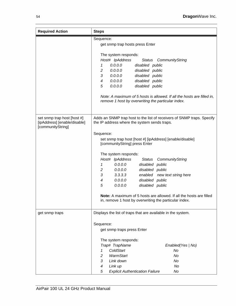
get snmp trap hosts Displays a list of receivers of SNMP traps.
Version 2.0
54 DragonWave Inc.
Required Action Steps
Sequence: get snmp trap hosts press Enter The system responds: Host# IpAddress Status CommunityString 1 0.0.0.0 disabled public 2 0.0.0.0 disabled public 3 0.0.0.0 disabled public 4 0.0.0.0 disabled public 5 0.0.0.0 disabled public Note: A maximum of 5 hosts is allowed. If all the hosts are filled in, remove 1 host by overwriting the particular index.
set snmp trap host [host #] [ipAddress] [enable/disable] [communityString]
Adds an SNMP trap host to the list of receivers of SNMP traps. Specify the IP address where the system sends traps. Sequence:
set snmp trap host [host #] [ipAddress] [enable/disable] [communityString] press Enter The system responds: Host# IpAddress Status CommunityString 1 0.0.0.0 disabled public 2 0.0.0.0 disabled public 3 3.3.3.3 enabled new text string here 4 0.0.0.0 disabled public 5 0.0.0.0 disabled public Note: A maximum of 5 hosts are allowed. If all the hosts are filled in, remove 1 host by overwriting the particular index.
get snmp traps Displays the list of traps that are available in the system. Sequence:
get snmp traps press Enter The system responds: Trap# TrapName Enabled(Yes | No) 1 ColdStart No 2 WarmStart No 3 Link down No 4 Link up No 5 Explicit Authentication Failure No
AirPair 100 UL 24 GHz Product Manual
Setting up the SNMP 55
Required Action Steps
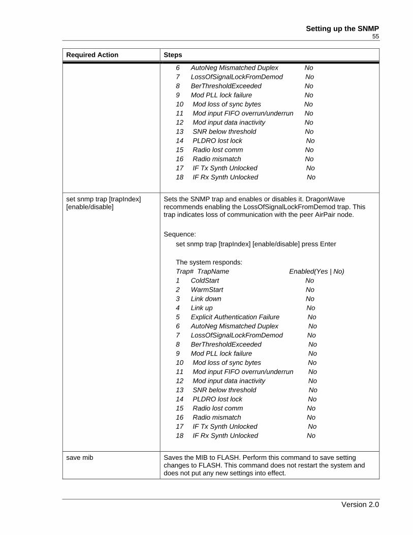
6 AutoNeg Mismatched Duplex No 7 LossOfSignalLockFromDemod No 8 BerThresholdExceeded No 9 Mod PLL lock failure No 10 Mod loss of sync bytes No 11 Mod input FIFO overrun/underrun No 12 Mod input data inactivity No 13 SNR below threshold No 14 PLDRO lost lock No 15 Radio lost comm No 16 Radio mismatch No 17 IF Tx Synth Unlocked No 18 IF Rx Synth Unlocked No
set snmp trap [trapIndex] [enable/disable]
Sets the SNMP trap and enables or disables it. DragonWave recommends enabling the LossOfSignalLockFromDemod trap. This trap indicates loss of communication with the peer AirPair node. Sequence:
set snmp trap [trapIndex] [enable/disable] press Enter The system responds: Trap# TrapName Enabled(Yes | No) 1 ColdStart No 2 WarmStart No 3 Link down No 4 Link up No 5 Explicit Authentication Failure No 6 AutoNeg Mismatched Duplex No 7 LossOfSignalLockFromDemod No 8 BerThresholdExceeded No 9 Mod PLL lock failure No 10 Mod loss of sync bytes No 11 Mod input FIFO overrun/underrun No 12 Mod input data inactivity No 13 SNR below threshold No 14 PLDRO lost lock No 15 Radio lost comm No 16 Radio mismatch No 17 IF Tx Synth Unlocked No 18 IF Rx Synth Unlocked No
save mib Saves the MIB to FLASH. Perform this command to save setting changes to FLASH. This command does not restart the system and does not put any new settings into effect.
Version 2.0
56 DragonWave Inc.
Required Action Steps
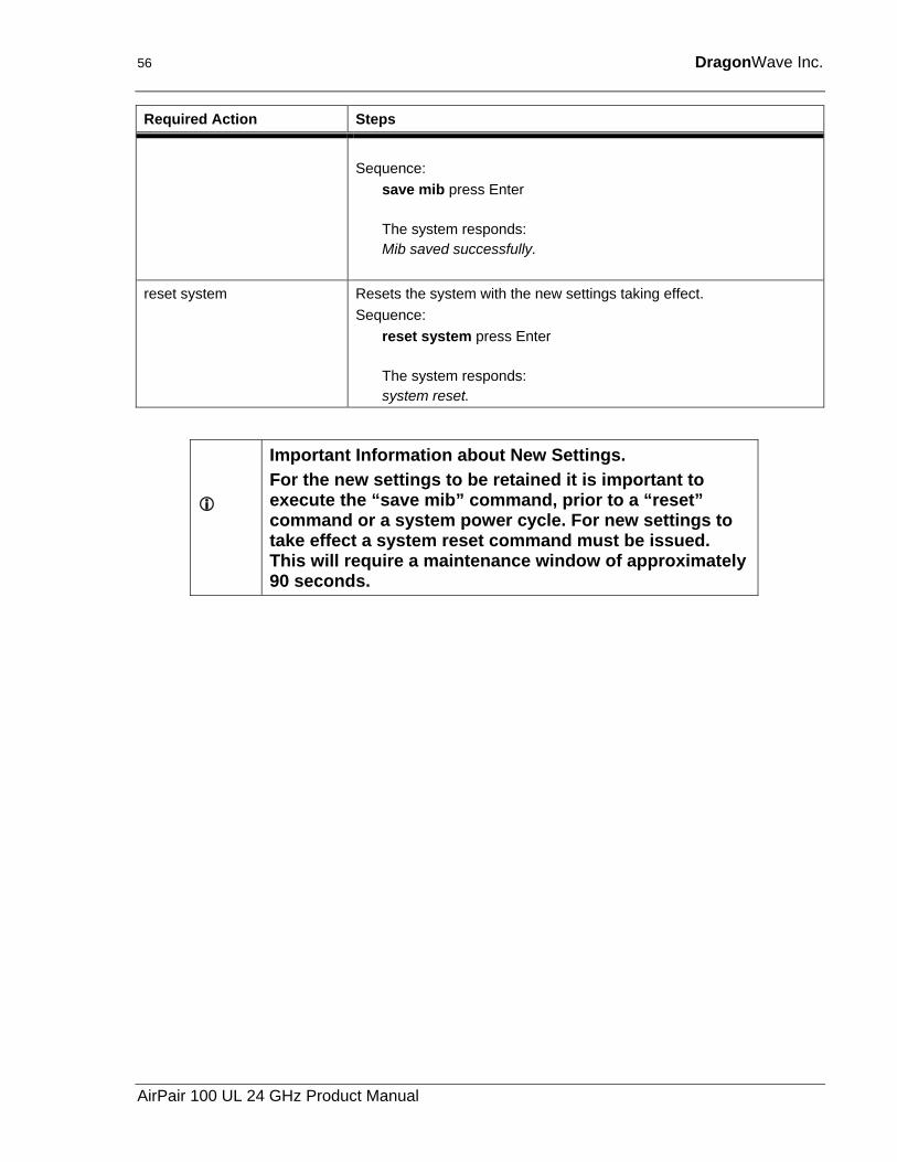
Sequence:
save mib press Enter The system responds: Mib saved successfully.
reset system Resets the system with the new settings taking effect. Sequence:
reset system press Enter The system responds: system reset.
Important Information about New Settings. For the new settings to be retained it is important to execute the “save mib” command, prior to a “reset” command or a system power cycle. For new settings to take effect a system reset command must be issued. This will require a maintenance window of approximately 90 seconds.
AirPair 100 UL 24 GHz Product Manual
8. Technical Support DragonWave provides technical support on all products shipped to Customers. Our Technical Support centre provides support 7 days a week and 24 hours per day. The centre is staffed by the DragonWave technical support during normal office hours, (Monday – Friday between 9:00 AM and 5:00 PM Eastern Standard Time). After hours the calls are routed to a cell phone / pager to reach the technical support engineer on call.
The contact details for DragonWave Technical Support are as follows:
Telephone: (613) 271 - 7010
Fax: (613) 599 – 4225
Email : [email protected]
Web Site: http://www.dragonwaveinc.com/contactus/support
Or http://support.dragonwaveinc.com

58 DragonWave Inc.
This page is intentionally left blank.
AirPair 100 UL 24 GHz Product Manual
9. Notice Information contained in this document is subject to change without notice. DragonWave Inc. shall not be liable for errors contained herein or for incidental or consequential damages in connection with the furnishings, performance, or use of the material.
9.1. Copyright © Copyright 2000-2003 by DragonWave Inc. All rights reserved. This document contains confidential information, which is proprietary to DragonWave Inc. No part of this publication can be reproduced or transmitted in any form or by any means, electronic or mechanical, including photocopying and recording, or by any information storage or retrieval system, without prior written consent from DragonWave Inc.
The DragonWave logo and design, DragonWave, AirPair and DragonLink are trademarks of DragonWave Inc. Other brand names used in this publication are trademarks or registered trademarks of their respective owners.

60 DragonWave Inc.
This page is intentionally left blank.
AirPair 100 UL 24 GHz Product Manual
Appendix A - Frequency Channel Plans
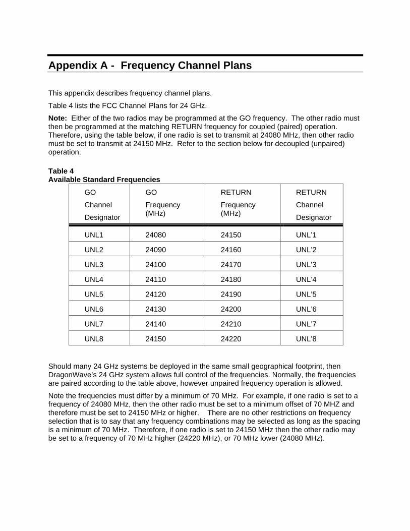
This appendix describes frequency channel plans.
Table 4 lists the FCC Channel Plans for 24 GHz.
Note: Either of the two radios may be programmed at the GO frequency. The other radio must then be programmed at the matching RETURN frequency for coupled (paired) operation. Therefore, using the table below, if one radio is set to transmit at 24080 MHz, then other radio must be set to transmit at 24150 MHz. Refer to the section below for decoupled (unpaired) operation. Table 4 Available Standard Frequencies
GO
Channel
Designator
GO
Frequency (MHz)
RETURN
Frequency (MHz)
RETURN
Channel
Designator
UNL1 24080 24150 UNL’1
UNL2 24090 24160 UNL’2
UNL3 24100 24170 UNL’3
UNL4 24110 24180 UNL’4
UNL5 24120 24190 UNL’5
UNL6 24130 24200 UNL’6
UNL7 24140 24210 UNL’7
UNL8 24150 24220 UNL’8
Should many 24 GHz systems be deployed in the same small geographical footprint, then DragonWave’s 24 GHz system allows full control of the frequencies. Normally, the frequencies are paired according to the table above, however unpaired frequency operation is allowed.
Note the frequencies must differ by a minimum of 70 MHz. For example, if one radio is set to a frequency of 24080 MHz, then the other radio must be set to a minimum offset of 70 MHZ and therefore must be set to 24150 MHz or higher. There are no other restrictions on frequency selection that is to say that any frequency combinations may be selected as long as the spacing is a minimum of 70 MHz. Therefore, if one radio is set to 24150 MHz then the other radio may be set to a frequency of 70 MHz higher (24220 MHz), or 70 MHz lower (24080 MHz).
62 DragonWave Inc.
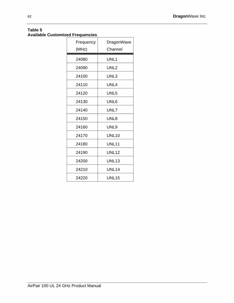
Table 5 Available Customized Frequencies
Frequency
(MHz)
DragonWave
Channel
24080 UNL1
24090 UNL2
24100 UNL3
24110 UNL4
24120 UNL5
24130 UNL6
24140 UNL7
24150 UNL8
24160 UNL9
24170 UNL10
24180 UNL11
24190 UNL12
24200 UNL13
24210 UNL14
24220 UNL15
AirPair 100 UL 24 GHz Product Manual

Appendix B - Mounting Instructions for 30 CM, 60 CM, 90cm Antennas
See the appropriate Antenna Mounting Instructions Manual. The Mounting Instruction Manual is shipped in the box with the mounting equipment and antenna.

64 DragonWave Inc.
This page is intentionally left blank.
AirPair 100 UL 24 GHz Product Manual
Appendix C - Command Line Interface (CLI) This section describes the Command Line Interface (CLI) commands used to configure AirPair and to obtain statistical and maintenance information.
Notes:
The modem serial port is always active, however you must press the <Enter> key in order to get a prompt.
1. On Power Up, the modem takes between 45 and 60 seconds to boot up.
2. Invalid Commands, or Commands that fail, receive a NAK as a response.
3. Radio Receiver gain is set to a default value due to the fixed cable length for the IF cable. Gain adjustments should only be made to the radio transmitter and not to the receiver gain.
4. The modem card modulation is set to QAM16 for AirPair 100 and QPSK for AirPair 50. Note: The factory-set IP address is 192.168.10.100.
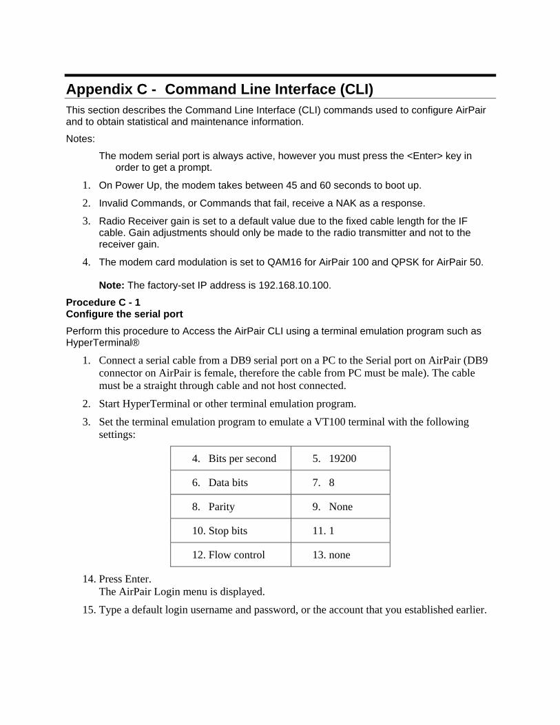
Procedure C - 1 Configure the serial port Perform this procedure to Access the AirPair CLI using a terminal emulation program such as HyperTerminal®
1. Connect a serial cable from a DB9 serial port on a PC to the Serial port on AirPair (DB9 connector on AirPair is female, therefore the cable from PC must be male). The cable must be a straight through cable and not host connected.
2. Start HyperTerminal or other terminal emulation program.
3. Set the terminal emulation program to emulate a VT100 terminal with the following settings:
4. Bits per second 5. 19200
6. Data bits 7. 8
8. Parity 9. None
10. Stop bits 11. 1
12. Flow control 13. none
14. Press Enter. The AirPair Login menu is displayed.
15. Type a default login username and password, or the account that you established earlier.
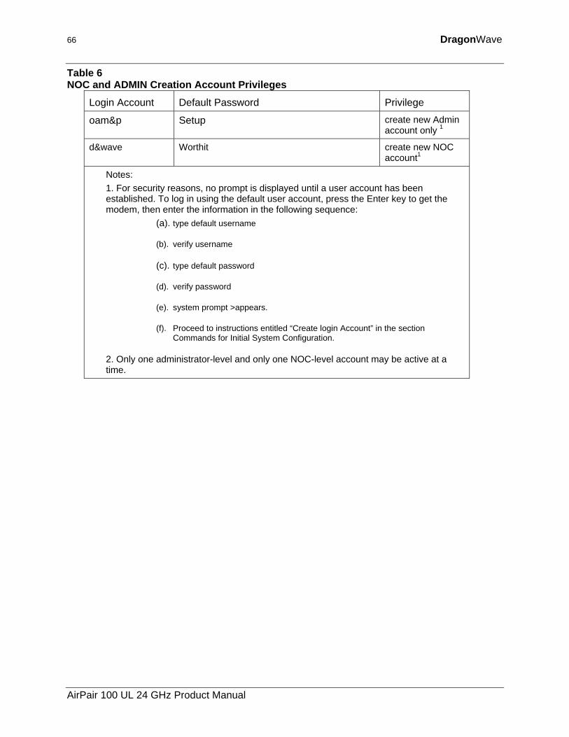
66 DragonWave
Table 6 NOC and ADMIN Creation Account Privileges
Login Account Default Password Privilege
oam&p Setup create new Admin account only 1
d&wave Worthit create new NOC account1
Notes: 1. For security reasons, no prompt is displayed until a user account has been established. To log in using the default user account, press the Enter key to get the modem, then enter the information in the following sequence:
(a). type default username
(b). verify username
(c). type default password
(d). verify password
(e). system prompt >appears.
(f). Proceed to instructions entitled “Create login Account” in the section Commands for Initial System Configuration.
2. Only one administrator-level and only one NOC-level account may be active at a time.
AirPair 100 UL 24 GHz Product Manual
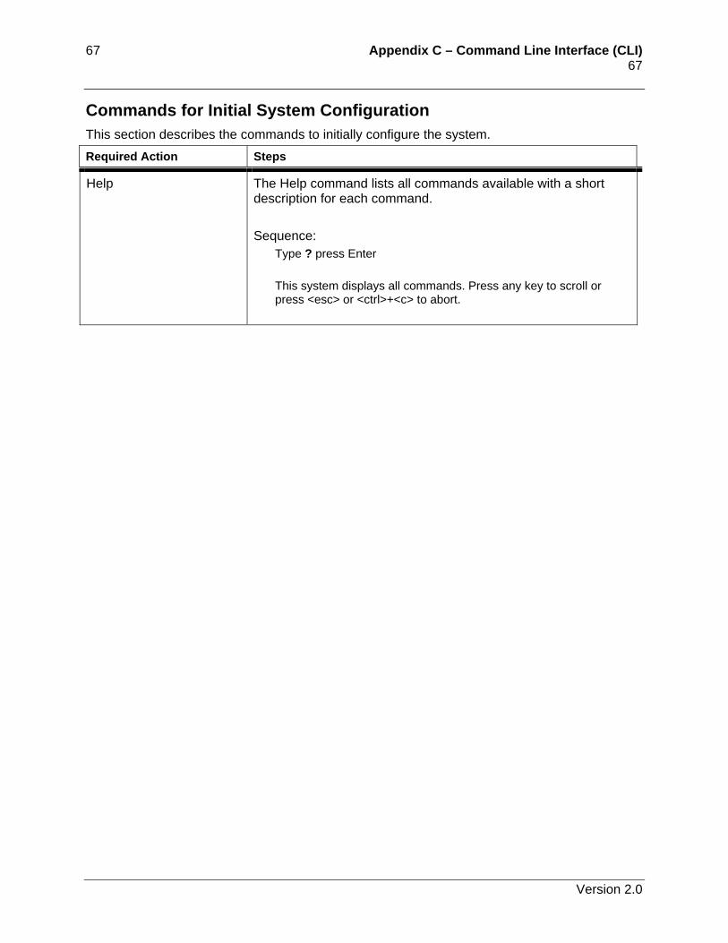
67 Appendix C – Command Line Interface (CLI) 67
Commands for Initial System Configuration This section describes the commands to initially configure the system. Required Action Steps
Help The Help command lists all commands available with a short description for each command. Sequence:
Type ? press Enter This system displays all commands. Press any key to scroll or press <esc> or <ctrl>+<c> to abort.
Version 2.0
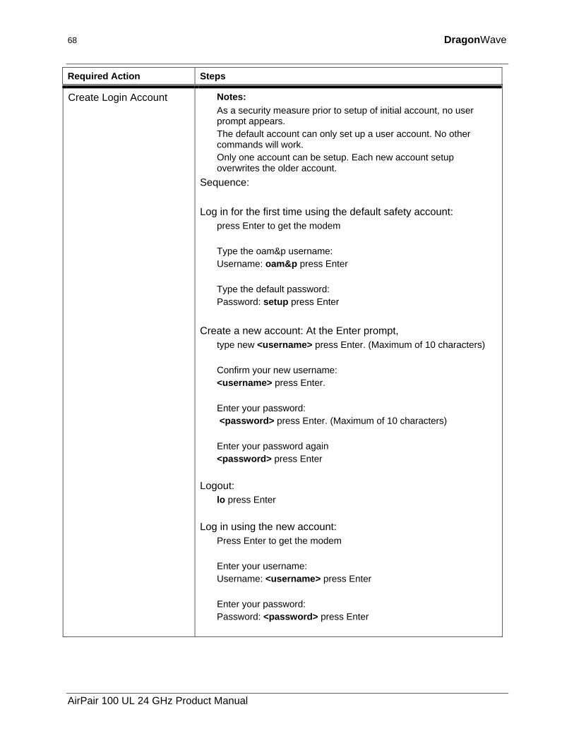
68 DragonWave
Required Action Steps
Create Login Account Notes: As a security measure prior to setup of initial account, no user prompt appears. The default account can only set up a user account. No other commands will work. Only one account can be setup. Each new account setup overwrites the older account.
Sequence: Log in for the first time using the default safety account:
press Enter to get the modem Type the oam&p username: Username: oam&p press Enter Type the default password: Password: setup press Enter
Create a new account: At the Enter prompt,
type new <username> press Enter. (Maximum of 10 characters) Confirm your new username: <username> press Enter. Enter your password: <password> press Enter. (Maximum of 10 characters) Enter your password again <password> press Enter
Logout: lo press Enter
Log in using the new account: Press Enter to get the modem Enter your username: Username: <username> press Enter Enter your password: Password: <password> press Enter
AirPair 100 UL 24 GHz Product Manual
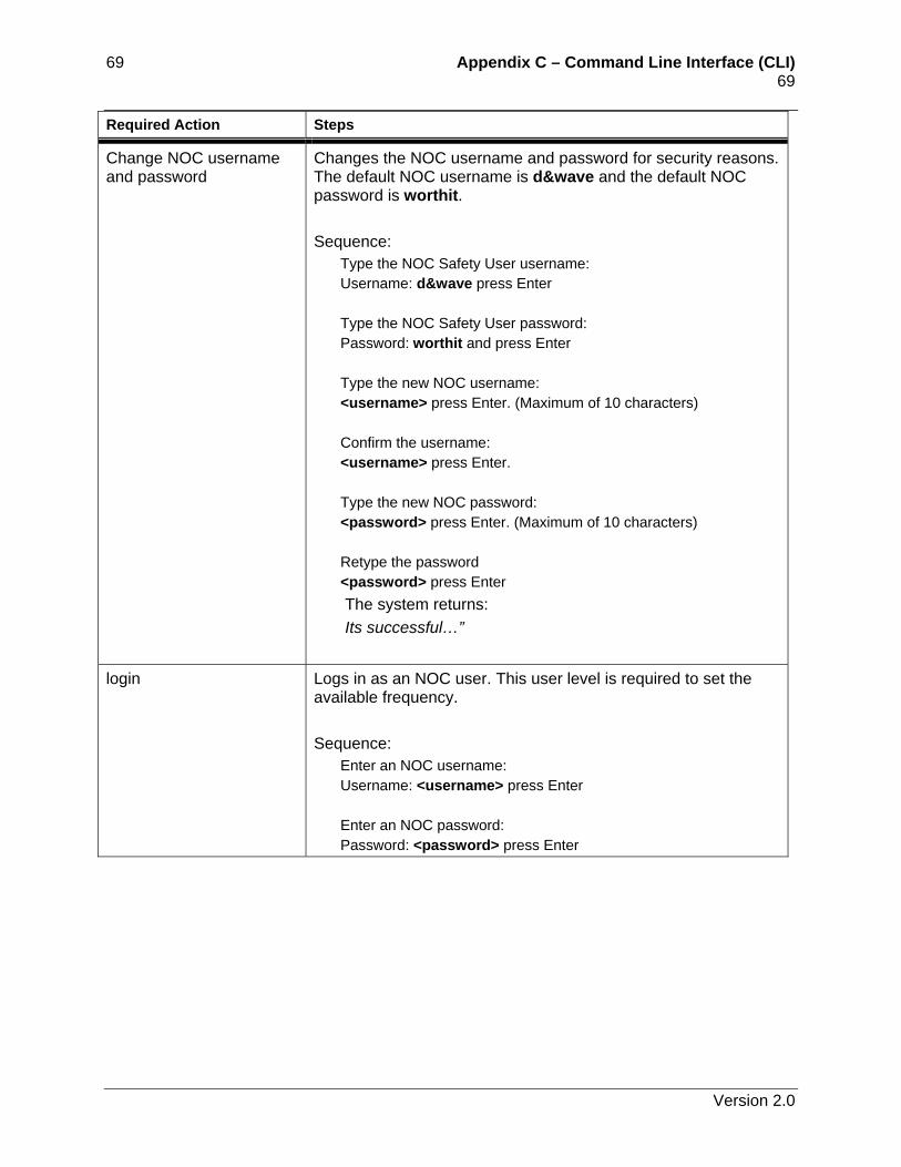
69 Appendix C – Command Line Interface (CLI) 69 Required Action Steps
Change NOC username and password
Changes the NOC username and password for security reasons. The default NOC username is d&wave and the default NOC password is worthit. Sequence:
Type the NOC Safety User username: Username: d&wave press Enter Type the NOC Safety User password: Password: worthit and press Enter Type the new NOC username: <username> press Enter. (Maximum of 10 characters) Confirm the username: <username> press Enter. Type the new NOC password: <password> press Enter. (Maximum of 10 characters) Retype the password <password> press Enter The system returns: Its successful…”
login Logs in as an NOC user. This user level is required to set the available frequency. Sequence:
Enter an NOC username: Username: <username> press Enter Enter an NOC password: Password: <password> press Enter
Version 2.0
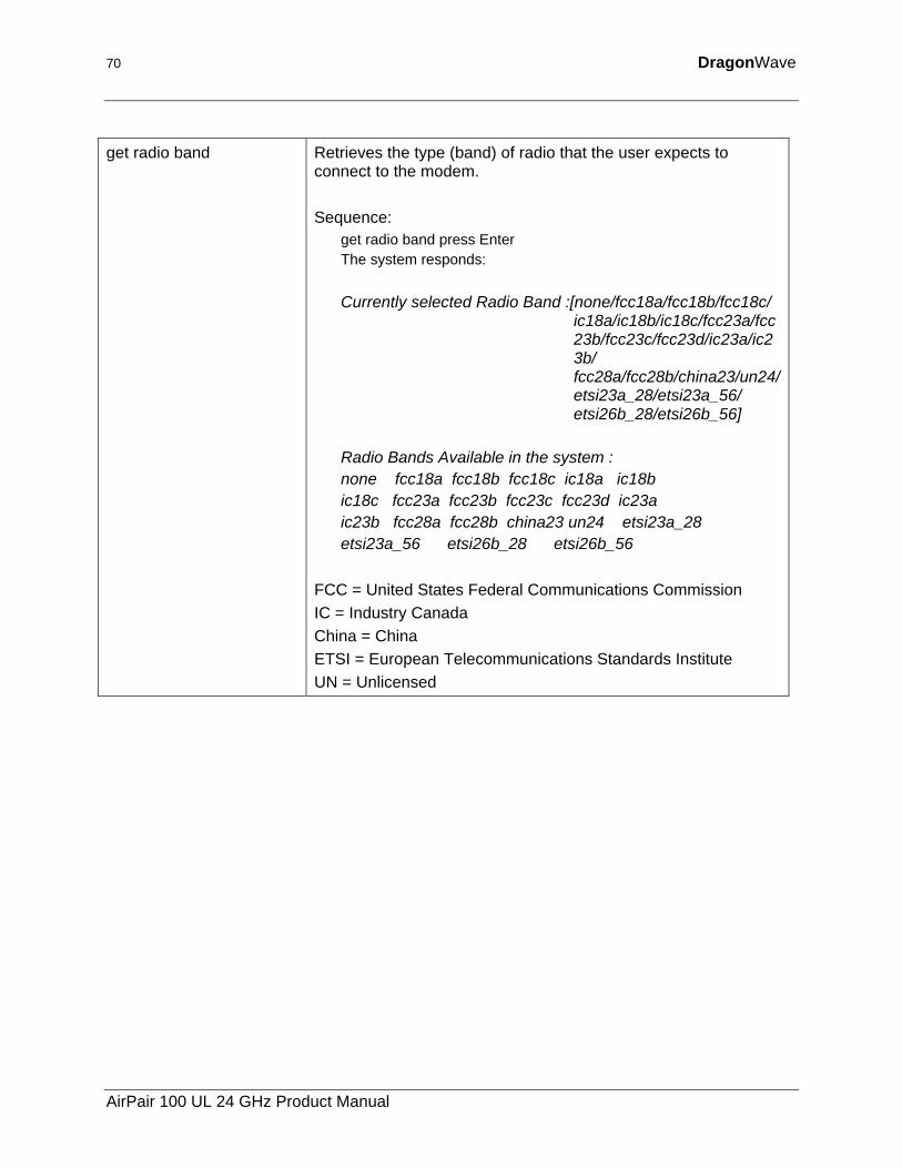
70 DragonWave
get radio band Retrieves the type (band) of radio that the user expects to connect to the modem. Sequence:
get radio band press Enter The system responds: Currently selected Radio Band :[none/fcc18a/fcc18b/fcc18c/
ic18a/ic18b/ic18c/fcc23a/fcc23b/fcc23c/fcc23d/ic23a/ic23b/ fcc28a/fcc28b/china23/un24/etsi23a_28/etsi23a_56/ etsi26b_28/etsi26b_56]
Radio Bands Available in the system : none fcc18a fcc18b fcc18c ic18a ic18b ic18c fcc23a fcc23b fcc23c fcc23d ic23a ic23b fcc28a fcc28b china23 un24 etsi23a_28 etsi23a_56 etsi26b_28 etsi26b_56
FCC = United States Federal Communications Commission IC = Industry Canada China = China ETSI = European Telecommunications Standards Institute UN = Unlicensed
AirPair 100 UL 24 GHz Product Manual
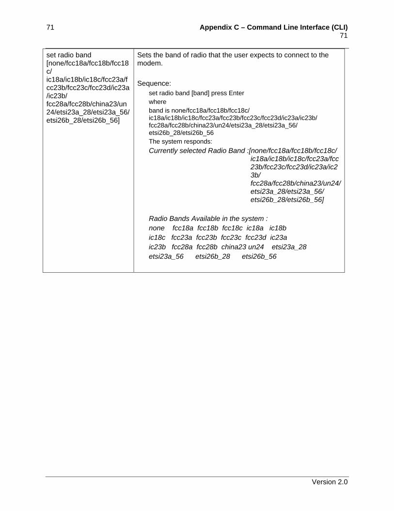
71 Appendix C – Command Line Interface (CLI) 71 set radio band [none/fcc18a/fcc18b/fcc18c/ ic18a/ic18b/ic18c/fcc23a/fcc23b/fcc23c/fcc23d/ic23a/ic23b/ fcc28a/fcc28b/china23/un24/etsi23a_28/etsi23a_56/ etsi26b_28/etsi26b_56]
Sets the band of radio that the user expects to connect to the modem. Sequence:
set radio band [band] press Enter where band is none/fcc18a/fcc18b/fcc18c/ ic18a/ic18b/ic18c/fcc23a/fcc23b/fcc23c/fcc23d/ic23a/ic23b/ fcc28a/fcc28b/china23/un24/etsi23a_28/etsi23a_56/ etsi26b_28/etsi26b_56 The system responds: Currently selected Radio Band :[none/fcc18a/fcc18b/fcc18c/
ic18a/ic18b/ic18c/fcc23a/fcc23b/fcc23c/fcc23d/ic23a/ic23b/ fcc28a/fcc28b/china23/un24/etsi23a_28/etsi23a_56/ etsi26b_28/etsi26b_56]
Radio Bands Available in the system : none fcc18a fcc18b fcc18c ic18a ic18b ic18c fcc23a fcc23b fcc23c fcc23d ic23a ic23b fcc28a fcc28b china23 un24 etsi23a_28 etsi23a_56 etsi26b_28 etsi26b_56
Version 2.0
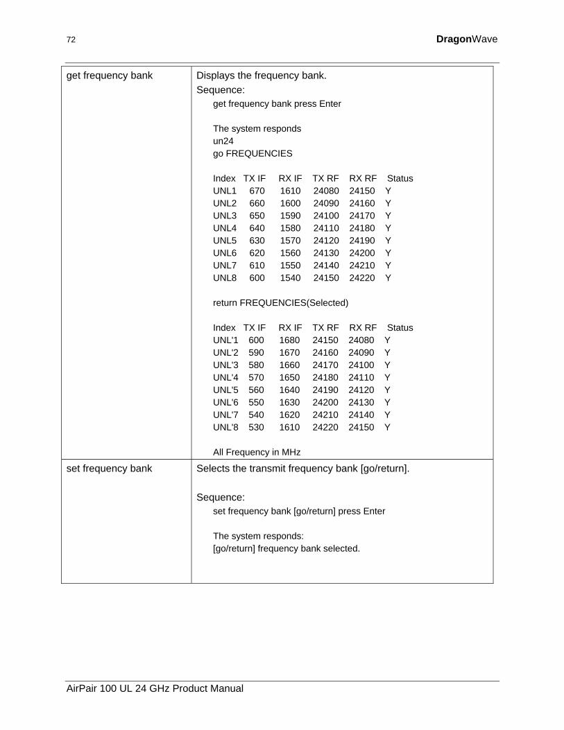
72 DragonWave
get frequency bank Displays the frequency bank. Sequence:
get frequency bank press Enter The system responds un24 go FREQUENCIES Index TX IF RX IF TX RF RX RF Status UNL1 670 1610 24080 24150 Y UNL2 660 1600 24090 24160 Y UNL3 650 1590 24100 24170 Y UNL4 640 1580 24110 24180 Y UNL5 630 1570 24120 24190 Y UNL6 620 1560 24130 24200 Y UNL7 610 1550 24140 24210 Y UNL8 600 1540 24150 24220 Y return FREQUENCIES(Selected) Index TX IF RX IF TX RF RX RF Status UNL'1 600 1680 24150 24080 Y UNL'2 590 1670 24160 24090 Y UNL'3 580 1660 24170 24100 Y UNL'4 570 1650 24180 24110 Y UNL'5 560 1640 24190 24120 Y UNL'6 550 1630 24200 24130 Y UNL'7 540 1620 24210 24140 Y UNL'8 530 1610 24220 24150 Y All Frequency in MHz
set frequency bank Selects the transmit frequency bank [go/return]. Sequence:
set frequency bank [go/return] press Enter The system responds: [go/return] frequency bank selected.
AirPair 100 UL 24 GHz Product Manual
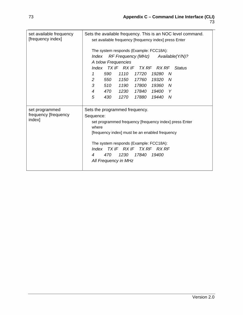
73 Appendix C – Command Line Interface (CLI) 73 set available frequency [frequency index]
Sets the available frequency. This is an NOC level command. set available frequency [frequency index] press Enter The system responds (Example: FCC18A): Index RF Frequency (MHz) Available(Y/N)? A txlow Frequencies Index TX IF RX IF TX RF RX RF Status 1 590 1110 17720 19280 N 2 550 1150 17760 19320 N 3 510 1190 17800 19360 N 4 470 1230 17840 19400 Y 5 430 1270 17880 19440 N
set programmed frequency [frequency index]
Sets the programmed frequency. Sequence:
set programmed frequency [frequency index] press Enter where [frequency index] must be an enabled frequency The system responds (Example: FCC18A): Index TX IF RX IF TX RF RX RF 4 470 1230 17840 19400 All Frequency in MHz
Version 2.0
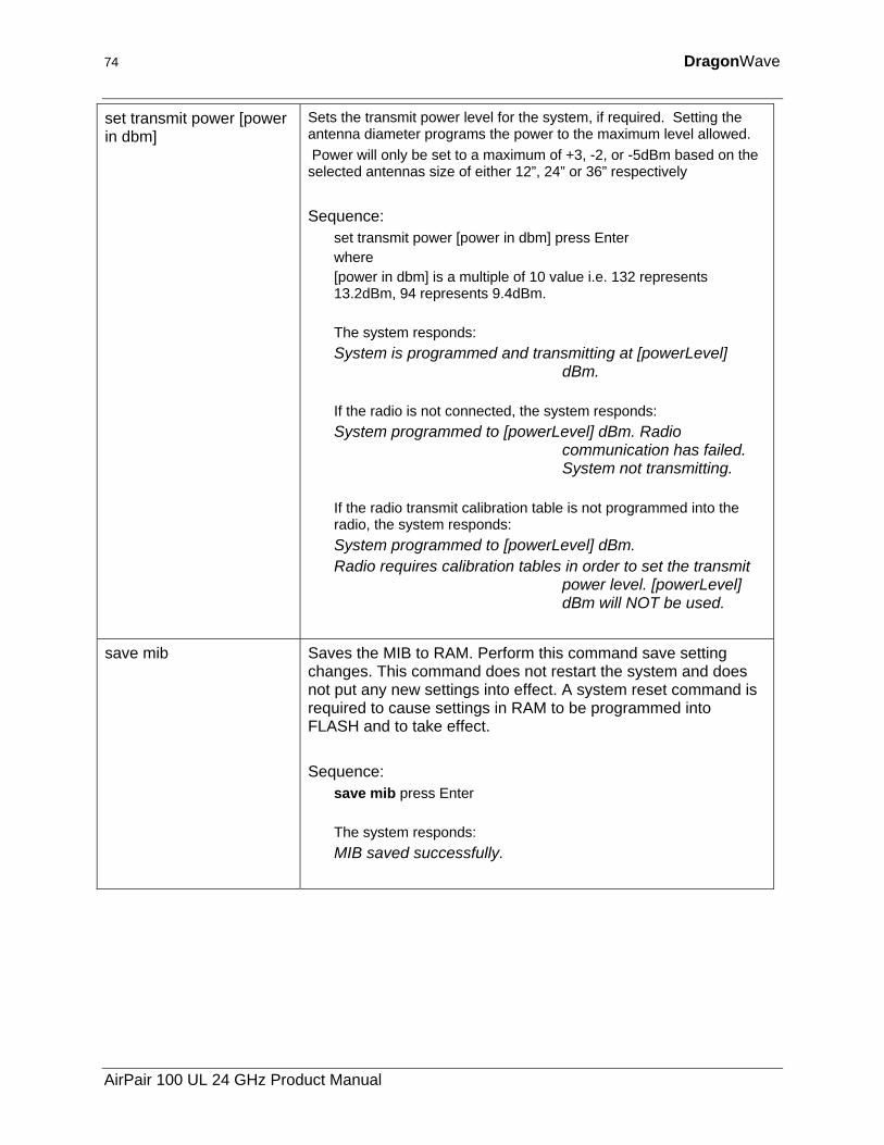
74 DragonWave
set transmit power [power in dbm]
Sets the transmit power level for the system, if required. Setting the antenna diameter programs the power to the maximum level allowed. Power will only be set to a maximum of +3, -2, or -5dBm based on the selected antennas size of either 12”, 24” or 36” respectively Sequence:
set transmit power [power in dbm] press Enter where [power in dbm] is a multiple of 10 value i.e. 132 represents 13.2dBm, 94 represents 9.4dBm. The system responds: System is programmed and transmitting at [powerLevel]
dBm. If the radio is not connected, the system responds: System programmed to [powerLevel] dBm. Radio
communication has failed. System not transmitting.
If the radio transmit calibration table is not programmed into the radio, the system responds: System programmed to [powerLevel] dBm. Radio requires calibration tables in order to set the transmit
power level. [powerLevel] dBm will NOT be used.
save mib Saves the MIB to RAM. Perform this command save setting changes. This command does not restart the system and does not put any new settings into effect. A system reset command is required to cause settings in RAM to be programmed into FLASH and to take effect. Sequence:
save mib press Enter The system responds: MIB saved successfully.
AirPair 100 UL 24 GHz Product Manual
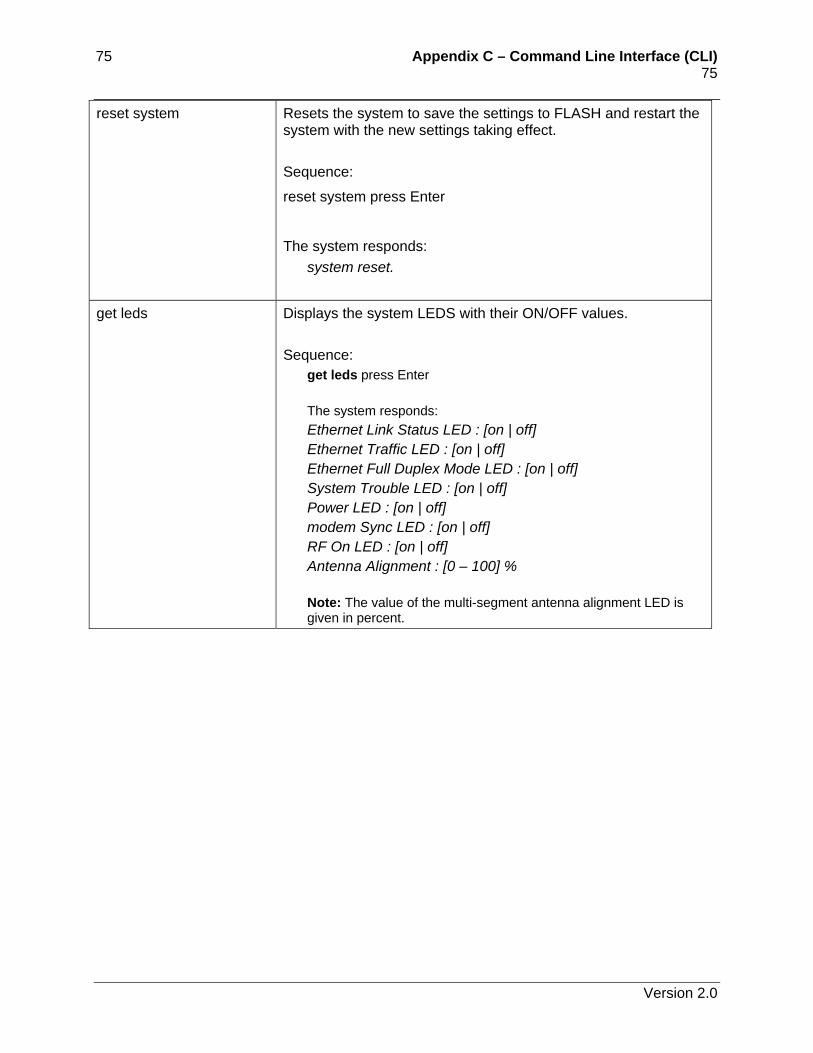
75 Appendix C – Command Line Interface (CLI) 75 reset system Resets the system to save the settings to FLASH and restart the
system with the new settings taking effect. Sequence:
reset system press Enter
The system responds: system reset.
get leds Displays the system LEDS with their ON/OFF values. Sequence:
get leds press Enter The system responds: Ethernet Link Status LED : [on | off] Ethernet Traffic LED : [on | off] Ethernet Full Duplex Mode LED : [on | off] System Trouble LED : [on | off] Power LED : [on | off] modem Sync LED : [on | off] RF On LED : [on | off] Antenna Alignment : [0 – 100] % Note: The value of the multi-segment antenna alignment LED is given in percent.
Version 2.0
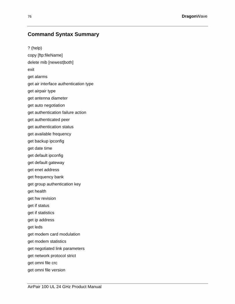
76 DragonWave
Command Syntax Summary
? (help)
copy [ftp:fileName]
delete mib [newest|both]
exit
get alarms
get air interface authentication type
get airpair type
get antenna diameter
get auto negotiation
get authentication failure action
get authenticated peer
get authentication status
get available frequency
get backup ipconfig
get date time
get default ipconfig
get default gateway
get enet address
get frequency bank
get group authentication key
get health
get hw revision
get if status
get if statistics
get ip address
get leds
get modem card modulation
get modem statistics
get negotiated link parameters
get network protocol strict
get omni file crc
get omni file version
AirPair 100 UL 24 GHz Product Manual
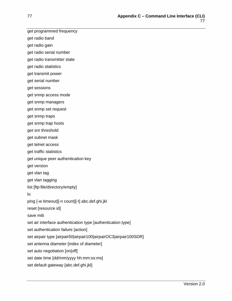
77 Appendix C – Command Line Interface (CLI) 77 get programmed frequency
get radio band
get radio gain
get radio serial number
get radio transmitter state
get radio statistics
get transmit power
get serial number
get sessions
get snmp access mode
get snmp managers
get snmp set request
get snmp traps
get snmp trap hosts
get snr threshold
get subnet mask
get telnet access
get traffic statistics
get unique peer authentication key
get version
get vlan tag
get vlan tagging
list [ftp:file/directory/empty]
lo
ping [-w timeout][-n count][-t] abc.def.ghi.jkl
reset [resource id]
save mib
set air interface authentication type [authentication type]
set authentication failure [action]
set airpair type [airpair50|airpair100|airpairOC3|airpair100SDR]
set antenna diameter [index of diameter]
set auto negotiation [on|off]
set date time [dd/mm/yyyy hh:mm:ss:ms]
set default gateway [abc.def.ghi.jkl]
Version 2.0
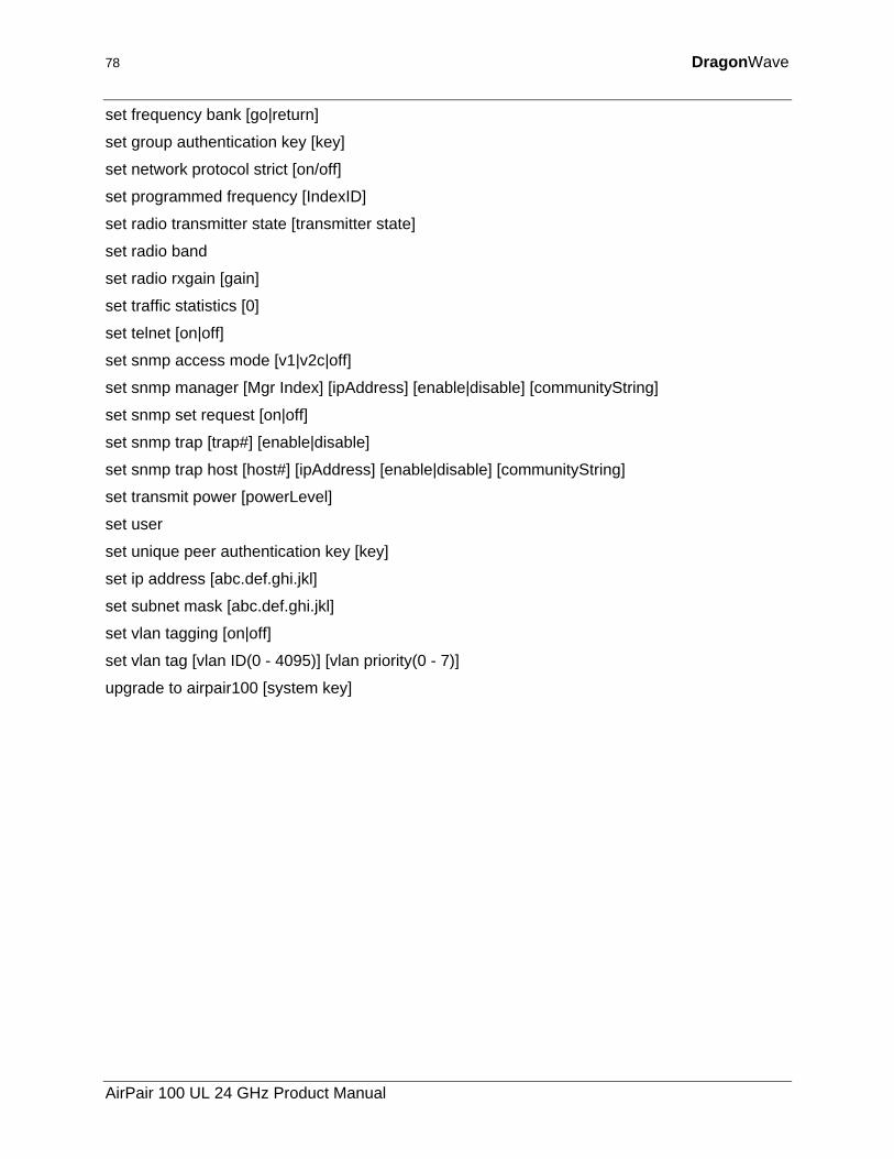
78 DragonWave
set frequency bank [go|return]
set group authentication key [key]
set network protocol strict [on/off]
set programmed frequency [IndexID]
set radio transmitter state [transmitter state]
set radio band
set radio rxgain [gain]
set traffic statistics [0]
set telnet [on|off]
set snmp access mode [v1|v2c|off]
set snmp manager [Mgr Index] [ipAddress] [enable|disable] [communityString]
set snmp set request [on|off]
set snmp trap [trap#] [enable|disable]
set snmp trap host [host#] [ipAddress] [enable|disable] [communityString]
set transmit power [powerLevel]
set user
set unique peer authentication key [key]
set ip address [abc.def.ghi.jkl]
set subnet mask [abc.def.ghi.jkl]
set vlan tagging [on|off]
set vlan tag [vlan ID(0 - 4095)] [vlan priority(0 - 7)]
upgrade to airpair100 [system key]
AirPair 100 UL 24 GHz Product Manual
79 Appendix C – Command Line Interface (CLI) 79
Complete List of CLI Commands This section shows a complete list of CLI commands. This document uses the following conventions to describe commands:
• <filename> or [newoldboth] - replace bolded information in brackets with the correct entry
• message — system responses and messages are shown in italics
• press Enter – instructs you to press the Enter key on your keyboard.
• NAK – system response indicating that the system cannot process the request. Repeat the action.
There are three keying features that simplify typing the commands. These features are:
• tab key - When you type the first few characters of a unique command you can press the tab key and the system fills in the rest of the command if there is a unique matching command. For example, when you type “get authentication s”, press tab and the system automatically fills in the rest of the “get authentication status” command.
• Enter key – To execute a command, press Enter.
• <esc> key – To abort a command, press the <esc> key.
• <ctrl>+c – To abort a command, press the <ctrl>+c.
• arrow keys – Use the arrow keys at the command line interface to scroll through the previous 20 issued commands.
Version 2.0
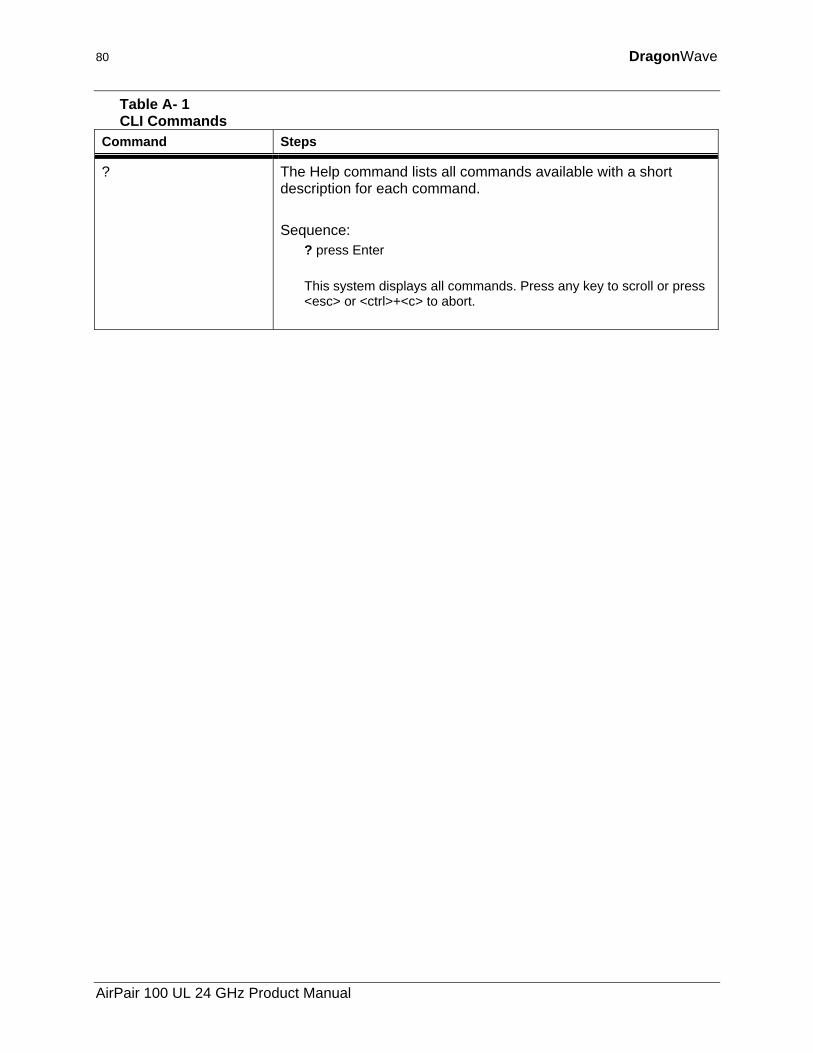
80 DragonWave
Table A- 1 CLI Commands
Command Steps
? The Help command lists all commands available with a short description for each command. Sequence:
? press Enter This system displays all commands. Press any key to scroll or press <esc> or <ctrl>+<c> to abort.
AirPair 100 UL 24 GHz Product Manual
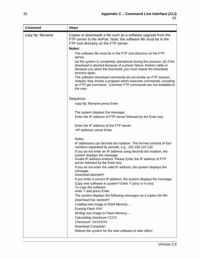
81 Appendix C – Command Line Interface (CLI) 81 Command Steps
copy ftp: filename Copies or downloads a file such as a software upgrade from the FTP server to the AirPair. Note: the software file must be in the FTP root directory on the FTP server. Notes:
The software file must be in the FTP root directory on the FTP server. (a) the system is completely operational during this process; (b) if the download is aborted because of a power failure, broken cable or because you abort the download, you must repeat the download process again. The software download commands do not invoke an FTP session. Instead, they invoke a program which executes commands, including an FTP get command. Common FTP commands are not available to the user.
Sequence:
copy ftp: filename press Enter The system displays the message: Enter the IP address of FTP server followed by the Enter key: Enter the IP address of the FTP server: <IP address> press Enter Notes: IP addresses use decimal dot notation. This format consists of four numbers separated by periods, e.g., 192.169.123.132. If you do not enter an IP address using decimal dot notation, the system displays the message: Invalid IP address entered. Please Enter the IP address of FTP server followed by the Enter key: If you do not enter the valid IP address, the system displays the message: Download aborted!!! If you enter a correct IP address, the system displays the message: Copy new software to system? Enter Y (yes) or N (no): To copy the software: enter Y and press Enter The system displays the following messages as it copies the file: Download has started!!! Loading new image in RAM Memory … Erasing Flash XXX Writing new image to Flash Memory … Calculating checksum CCCC Checksum: XXXXXXX Download Complete! Reboot the system for the new software to take effect.
Version 2.0
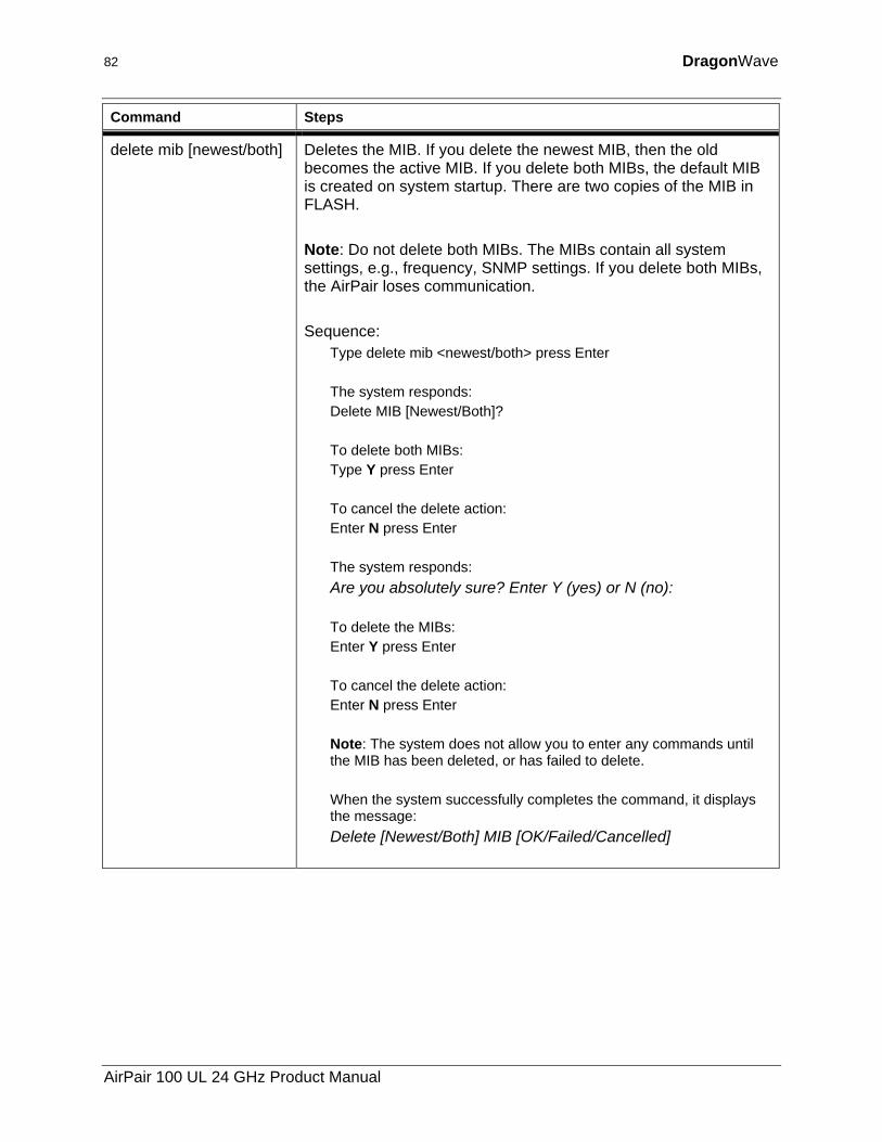
82 DragonWave
Command Steps
delete mib [newest/both] Deletes the MIB. If you delete the newest MIB, then the old becomes the active MIB. If you delete both MIBs, the default MIB is created on system startup. There are two copies of the MIB in FLASH. Note: Do not delete both MIBs. The MIBs contain all system settings, e.g., frequency, SNMP settings. If you delete both MIBs, the AirPair loses communication. Sequence:
Type delete mib <newest/both> press Enter The system responds: Delete MIB [Newest/Both]? To delete both MIBs: Type Y press Enter To cancel the delete action: Enter N press Enter The system responds: Are you absolutely sure? Enter Y (yes) or N (no): To delete the MIBs: Enter Y press Enter To cancel the delete action: Enter N press Enter Note: The system does not allow you to enter any commands until the MIB has been deleted, or has failed to delete. When the system successfully completes the command, it displays the message: Delete [Newest/Both] MIB [OK/Failed/Cancelled]
AirPair 100 UL 24 GHz Product Manual
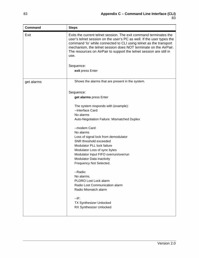
83 Appendix C – Command Line Interface (CLI) 83 Command Steps
Exit Exits the current telnet session. The exit command terminates the user’s telnet session on the user’s PC as well. If the user types the command ‘lo’ while connected to CLI using telnet as the transport mechanism, the telnet session does NOT terminate on the AirPair. The resources on AirPair to support the telnet session are still in use. Sequence:
exit press Enter
get alarms Shows the alarms that are present in the system.
Sequence:
get alarms press Enter The system responds with (example): --Interface Card: No alarms Auto-Negotiation Failure: Mismatched Duplex --modem Card: No alarms Loss of signal lock from demodulator SNR threshold exceeded Modulator PLL lock failure Modulator Loss of sync bytes Modulator Input FIFO overrun/overrun Modulator Data inactivity Frequency Not Selected. --Radio: No alarms. PLDRO Lost Lock alarm Radio Lost Communication alarm Radio Mismatch alarm --IF: TX Synthesizer Unlocked RX Synthesizer Unlocked
Version 2.0
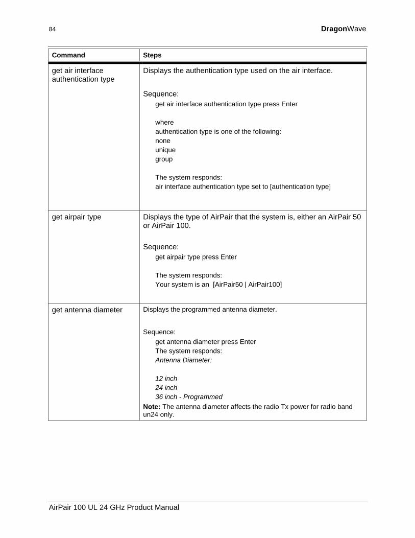
84 DragonWave
Command Steps
get air interface authentication type
Displays the authentication type used on the air interface.
Sequence:
get air interface authentication type press Enter where authentication type is one of the following: none unique group The system responds: air interface authentication type set to [authentication type]
get airpair type Displays the type of AirPair that the system is, either an AirPair 50 or AirPair 100. Sequence:
get airpair type press Enter The system responds: Your system is an [AirPair50 | AirPair100]
get antenna diameter Displays the programmed antenna diameter.
Sequence:
get antenna diameter press Enter The system responds: Antenna Diameter: 12 inch 24 inch 36 inch - Programmed
Note: The antenna diameter affects the radio Tx power for radio band un24 only.
AirPair 100 UL 24 GHz Product Manual
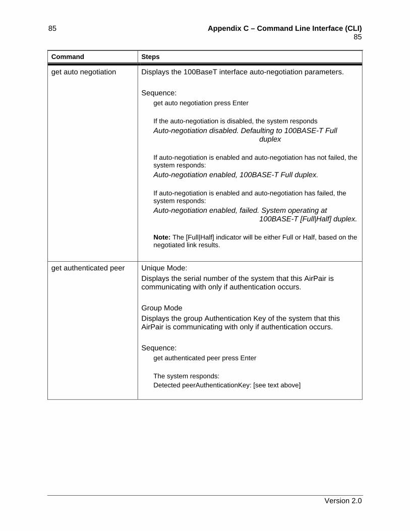
85 Appendix C – Command Line Interface (CLI) 85 Command Steps
get auto negotiation Displays the 100BaseT interface auto-negotiation parameters. Sequence:
get auto negotiation press Enter If the auto-negotiation is disabled, the system responds Auto-negotiation disabled. Defaulting to 100BASE-T Full
duplex If auto-negotiation is enabled and auto-negotiation has not failed, the system responds: Auto-negotiation enabled, 100BASE-T Full duplex. If auto-negotiation is enabled and auto-negotiation has failed, the system responds: Auto-negotiation enabled, failed. System operating at
100BASE-T [Full|Half] duplex. Note: The [Full|Half] indicator will be either Full or Half, based on the negotiated link results.
get authenticated peer Unique Mode: Displays the serial number of the system that this AirPair is communicating with only if authentication occurs. Group Mode Displays the group Authentication Key of the system that this AirPair is communicating with only if authentication occurs. Sequence:
get authenticated peer press Enter The system responds: Detected peerAuthenticationKey: [see text above]
Version 2.0
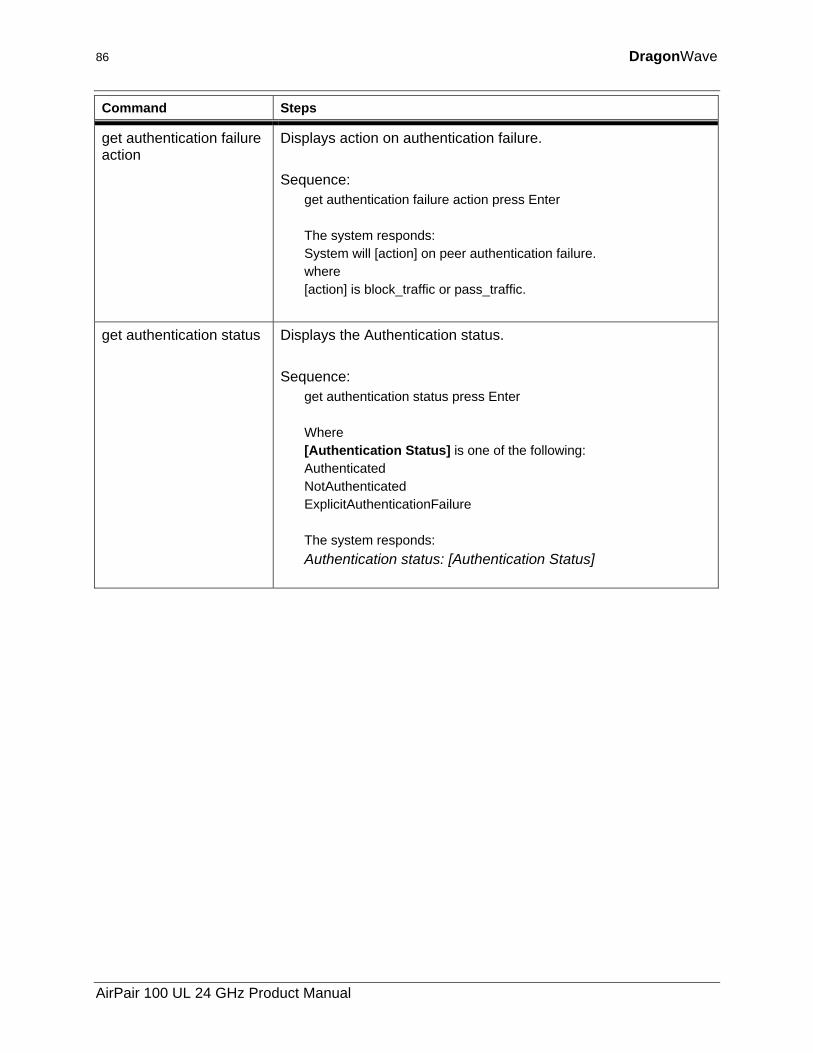
86 DragonWave
Command Steps
get authentication failure action
Displays action on authentication failure. Sequence:
get authentication failure action press Enter The system responds: System will [action] on peer authentication failure. where [action] is block_traffic or pass_traffic.
get authentication status Displays the Authentication status. Sequence:
get authentication status press Enter Where [Authentication Status] is one of the following: Authenticated NotAuthenticated ExplicitAuthenticationFailure The system responds: Authentication status: [Authentication Status]
AirPair 100 UL 24 GHz Product Manual
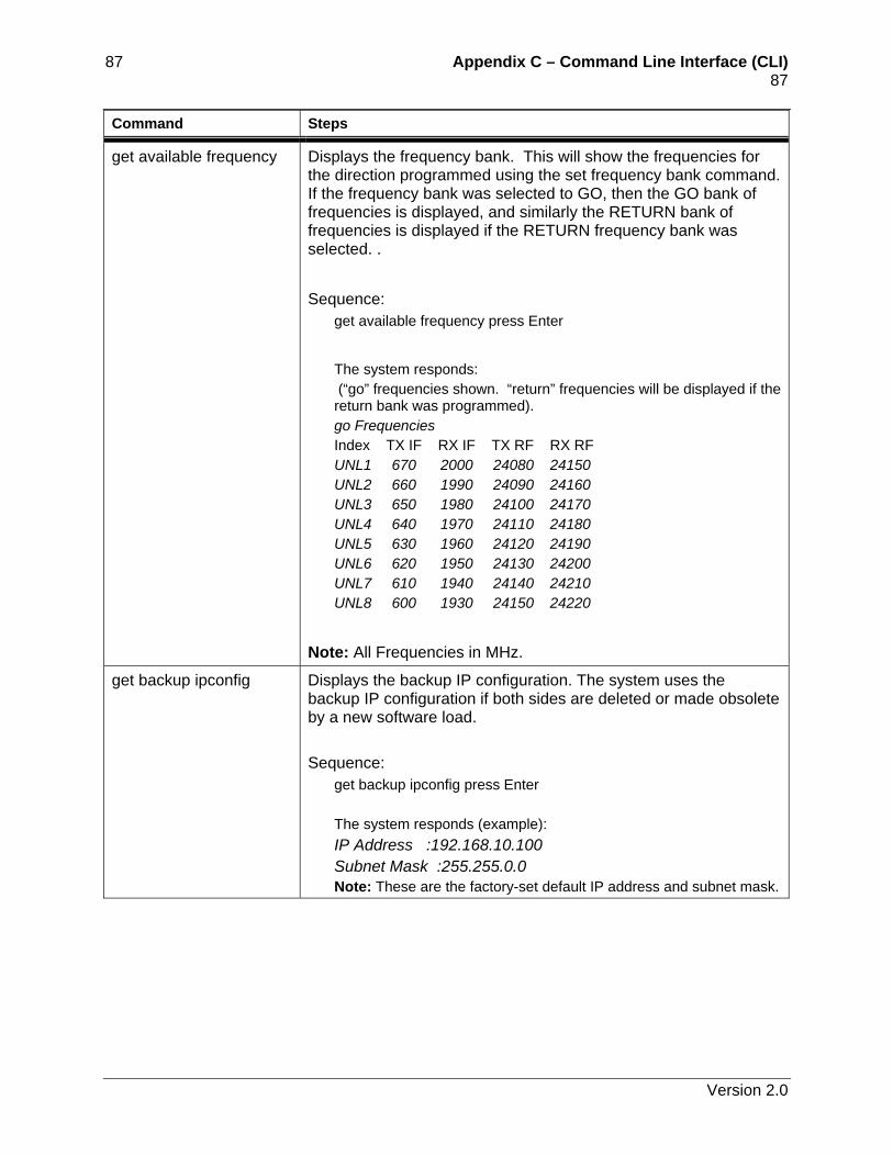
87 Appendix C – Command Line Interface (CLI) 87 Command Steps
get available frequency Displays the frequency bank. This will show the frequencies for the direction programmed using the set frequency bank command. If the frequency bank was selected to GO, then the GO bank of frequencies is displayed, and similarly the RETURN bank of frequencies is displayed if the RETURN frequency bank was selected. .
Sequence:
get available frequency press Enter
The system responds: (“go” frequencies shown. “return” frequencies will be displayed if the return bank was programmed). go Frequencies Index TX IF RX IF TX RF RX RF UNL1 670 2000 24080 24150 UNL2 660 1990 24090 24160 UNL3 650 1980 24100 24170 UNL4 640 1970 24110 24180 UNL5 630 1960 24120 24190 UNL6 620 1950 24130 24200 UNL7 610 1940 24140 24210 UNL8 600 1930 24150 24220
Note: All Frequencies in MHz.
get backup ipconfig Displays the backup IP configuration. The system uses the backup IP configuration if both sides are deleted or made obsolete by a new software load. Sequence:
get backup ipconfig press Enter The system responds (example): IP Address :192.168.10.100 Subnet Mask :255.255.0.0 Note: These are the factory-set default IP address and subnet mask.
Version 2.0
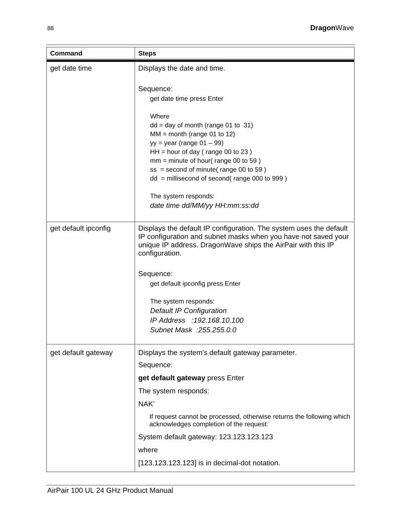
88 DragonWave
Command Steps
get date time Displays the date and time. Sequence:
get date time press Enter Where dd = day of month (range 01 to 31) MM = month (range 01 to 12) yy = year (range 01 – 99) HH = hour of day ( range 00 to 23 ) mm = minute of hour( range 00 to 59 ) ss = second of minute( range 00 to 59 ) dd = millisecond of second( range 000 to 999 ) The system responds: date time dd/MM/yy HH:mm:ss:dd
get default ipconfig Displays the default IP configuration. The system uses the default IP configuration and subnet masks when you have not saved your unique IP address. DragonWave ships the AirPair with this IP configuration. Sequence:
get default ipconfig press Enter The system responds: Default IP Configuration IP Address :192.168.10.100 Subnet Mask :255.255.0.0
get default gateway Displays the system's default gateway parameter.
Sequence:
get default gateway press Enter
The system responds:
NAK’
If request cannot be processed, otherwise returns the following which acknowledges completion of the request:
System default gateway: 123.123.123.123
where
[123.123.123.123] is in decimal-dot notation.
AirPair 100 UL 24 GHz Product Manual
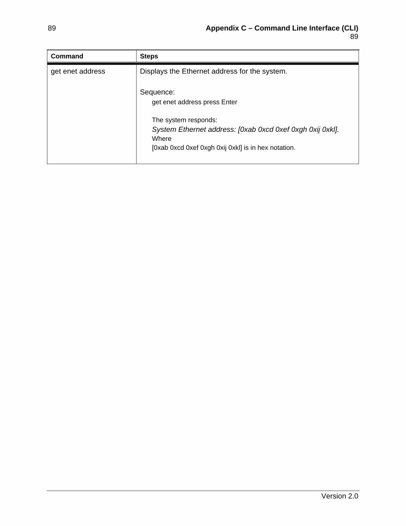
89 Appendix C – Command Line Interface (CLI) 89 Command Steps
get enet address Displays the Ethernet address for the system. Sequence:
get enet address press Enter The system responds: System Ethernet address: [0xab 0xcd 0xef 0xgh 0xij 0xkl]. Where [0xab 0xcd 0xef 0xgh 0xij 0xkl] is in hex notation.
Version 2.0
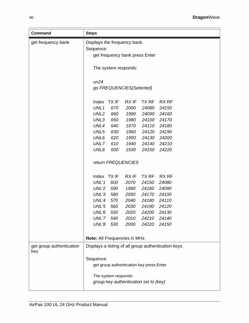
90 DragonWave
Command Steps
get frequency bank Displays the frequency bank. Sequence:
get frequency bank press Enter
The system responds:
un24 go FREQUENCIES(Selected)
Index TX IF RX IF TX RF RX RF UNL1 670 2000 24080 24150 UNL2 660 1990 24090 24160 UNL3 650 1980 24100 24170 UNL4 640 1970 24110 24180 UNL5 630 1960 24120 24190 UNL6 620 1950 24130 24200 UNL7 610 1940 24140 24210 UNL8 600 1930 24150 24220
return FREQUENCIES
Index TX IF RX IF TX RF RX RF UNL'1 600 2070 24150 24080 UNL'2 590 1990 24160 24090 UNL'3 580 2050 24170 24100 UNL'4 570 2040 24180 24110 UNL'5 560 2030 24190 24120 UNL'6 550 2020 24200 24130 UNL'7 540 2010 24210 24140 UNL'8 530 2000 24220 24150
Note: All Frequencies in MHz.
get group authentication key
Displays a listing of all group authentication keys. Sequence:
get group authentication key press Enter The system responds: group key authentication set to [key]
AirPair 100 UL 24 GHz Product Manual
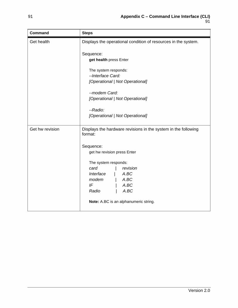
91 Appendix C – Command Line Interface (CLI) 91 Command Steps
Get health Displays the operational condition of resources in the system. Sequence:
get health press Enter The system responds: --Interface Card: [Operational | Not Operational] --modem Card: [Operational | Not Operational] --Radio: [Operational | Not Operational]
Get hw revision Displays the hardware revisions in the system in the following format: Sequence:
get hw revision press Enter The system responds: card | revision Interface | A.BC modem | A.BC IF | A.BC Radio | A.BC Note: A.BC is an alphanumeric string.
Version 2.0
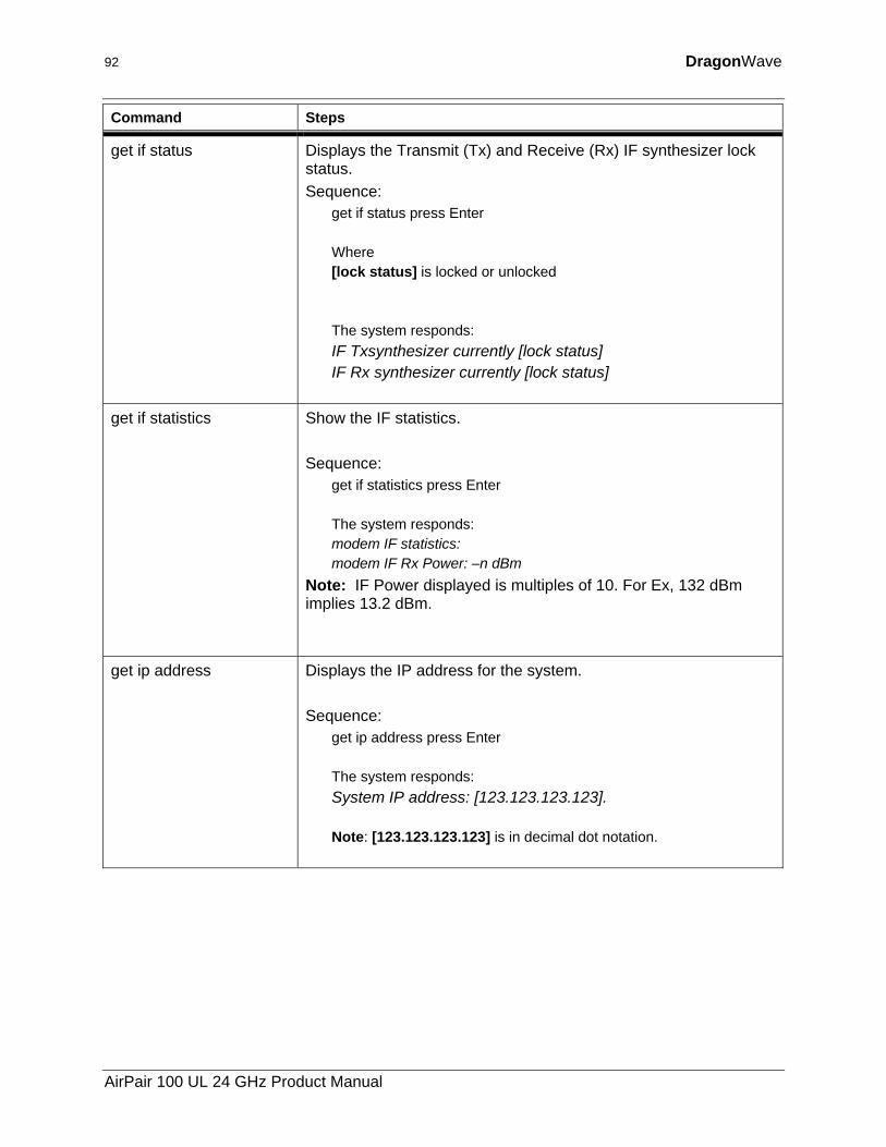
92 DragonWave
Command Steps
get if status Displays the Transmit (Tx) and Receive (Rx) IF synthesizer lock status. Sequence:
get if status press Enter Where [lock status] is locked or unlocked The system responds: IF Txsynthesizer currently [lock status] IF Rx synthesizer currently [lock status]
get if statistics Show the IF statistics. Sequence:
get if statistics press Enter The system responds: modem IF statistics: modem IF Rx Power: –n dBm
Note: IF Power displayed is multiples of 10. For Ex, 132 dBm implies 13.2 dBm.
get ip address Displays the IP address for the system. Sequence:
get ip address press Enter The system responds: System IP address: [123.123.123.123]. Note: [123.123.123.123] is in decimal dot notation.
AirPair 100 UL 24 GHz Product Manual
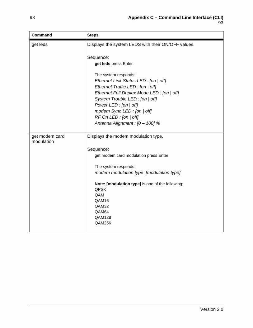
93 Appendix C – Command Line Interface (CLI) 93 Command Steps
get leds Displays the system LEDS with their ON/OFF values. Sequence:
get leds press Enter The system responds: Ethernet Link Status LED : [on | off] Ethernet Traffic LED : [on | off] Ethernet Full Duplex Mode LED : [on | off] System Trouble LED : [on | off] Power LED : [on | off] modem Sync LED : [on | off] RF On LED : [on | off] Antenna Alignment : [0 – 100] %
get modem card modulation
Displays the modem modulation type. Sequence:
get modem card modulation press Enter The system responds: modem modulation type [modulation type] Note: [modulation type] is one of the following: QPSK QAM QAM16 QAM32 QAM64 QAM128 QAM256
Version 2.0
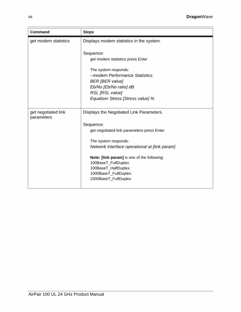
94 DragonWave
Command Steps
get modem statistics Displays modem statistics in the system. Sequence:
get modem statistics press Enter The system responds: --modem Performance Statistics: BER [BER value] Eb/No [Eb/No ratio] dB RSL [RSL value] Equalizer Stress [Stress value] %
get negotiated link parameters
Displays the Negotiated Link Parameters. Sequence:
get negotiated link parameters press Enter The system responds: Network Interface operational at [link param] Note: [link param] is one of the following: 100BaseT_FullDuplex 100BaseT_HalfDuplex 1000BaseT_FullDuplex 1000BaseT_FullDuplex
AirPair 100 UL 24 GHz Product Manual
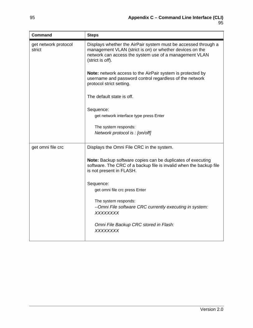
95 Appendix C – Command Line Interface (CLI) 95 Command Steps
get network protocol strict
Displays whether the AirPair system must be accessed through a management VLAN (strict is on) or whether devices on the network can access the system use of a management VLAN (strict is off). Note: network access to the AirPair system is protected by username and password control regardless of the network protocol strict setting. The default state is off. Sequence:
get network interface type press Enter The system responds: Network protocol is : [on/off]
get omni file crc Displays the Omni File CRC in the system. Note: Backup software copies can be duplicates of executing software. The CRC of a backup file is invalid when the backup file is not present in FLASH. Sequence:
get omni file crc press Enter The system responds: --Omni File software CRC currently executing in system: XXXXXXXX Omni File Backup CRC stored in Flash: XXXXXXXX
Version 2.0
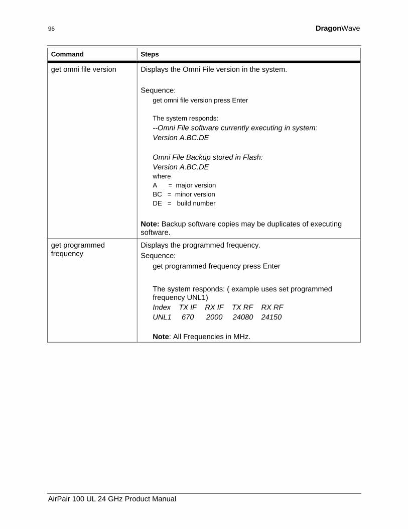
96 DragonWave
Command Steps
get omni file version Displays the Omni File version in the system. Sequence:
get omni file version press Enter The system responds: --Omni File software currently executing in system: Version A.BC.DE Omni File Backup stored in Flash: Version A.BC.DE where A = major version BC = minor version DE = build number
Note: Backup software copies may be duplicates of executing software.
get programmed frequency
Displays the programmed frequency. Sequence:
get programmed frequency press Enter
The system responds: ( example uses set programmed frequency UNL1) Index TX IF RX IF TX RF RX RF UNL1 670 2000 24080 24150 Note: All Frequencies in MHz.
AirPair 100 UL 24 GHz Product Manual
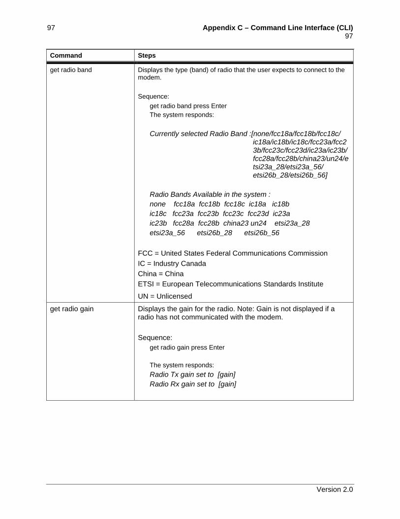
97 Appendix C – Command Line Interface (CLI) 97 Command Steps
get radio band Displays the type (band) of radio that the user expects to connect to the modem. Sequence:
get radio band press Enter The system responds: Currently selected Radio Band :[none/fcc18a/fcc18b/fcc18c/
ic18a/ic18b/ic18c/fcc23a/fcc23b/fcc23c/fcc23d/ic23a/ic23b/ fcc28a/fcc28b/china23/un24/etsi23a_28/etsi23a_56/ etsi26b_28/etsi26b_56]
Radio Bands Available in the system : none fcc18a fcc18b fcc18c ic18a ic18b ic18c fcc23a fcc23b fcc23c fcc23d ic23a ic23b fcc28a fcc28b china23 un24 etsi23a_28 etsi23a_56 etsi26b_28 etsi26b_56
FCC = United States Federal Communications Commission IC = Industry Canada China = China ETSI = European Telecommunications Standards Institute
UN = Unlicensed
get radio gain Displays the gain for the radio. Note: Gain is not displayed if a radio has not communicated with the modem. Sequence:
get radio gain press Enter The system responds: Radio Tx gain set to [gain] Radio Rx gain set to [gain]
Version 2.0
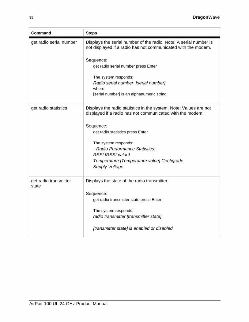
98 DragonWave
Command Steps
get radio serial number Displays the serial number of the radio. Note: A serial number is not displayed if a radio has not communicated with the modem. Sequence:
get radio serial number press Enter The system responds: Radio serial number [serial number] where [serial number] is an alphanumeric string.
get radio statistics Displays the radio statistics in the system. Note: Values are not displayed if a radio has not communicated with the modem. Sequence:
get radio statistics press Enter The system responds: --Radio Performance Statistics: RSSI [RSSI value] Temperature [Temperature value] Centigrade Supply Voltage
get radio transmitter state
Displays the state of the radio transmitter. Sequence:
get radio transmitter state press Enter The system responds: radio transmitter [transmitter state] [transmitter state] is enabled or disabled.
AirPair 100 UL 24 GHz Product Manual
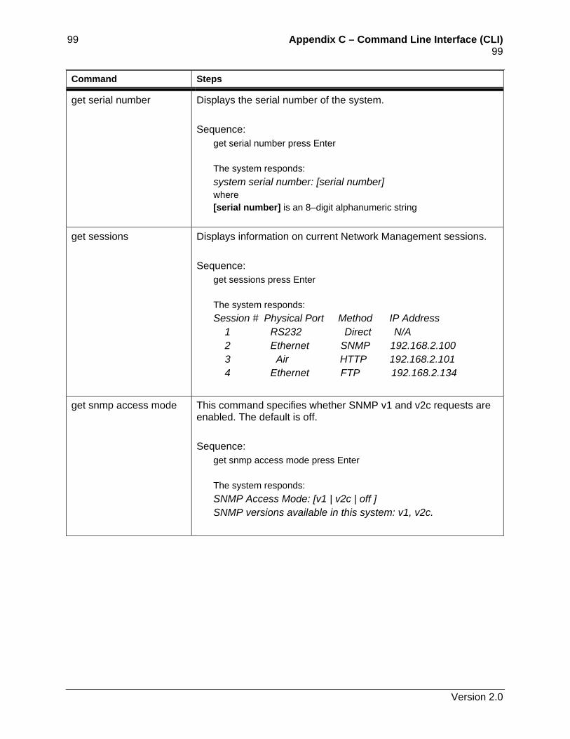
99 Appendix C – Command Line Interface (CLI) 99 Command Steps
get serial number Displays the serial number of the system. Sequence:
get serial number press Enter The system responds: system serial number: [serial number] where [serial number] is an 8–digit alphanumeric string
get sessions Displays information on current Network Management sessions. Sequence:
get sessions press Enter The system responds: Session # Physical Port Method IP Address 1 RS232 Direct N/A 2 Ethernet SNMP 192.168.2.100 3 Air HTTP 192.168.2.101 4 Ethernet FTP 192.168.2.134
get snmp access mode This command specifies whether SNMP v1 and v2c requests are enabled. The default is off. Sequence:
get snmp access mode press Enter The system responds: SNMP Access Mode: [v1 | v2c | off ] SNMP versions available in this system: v1, v2c.
Version 2.0
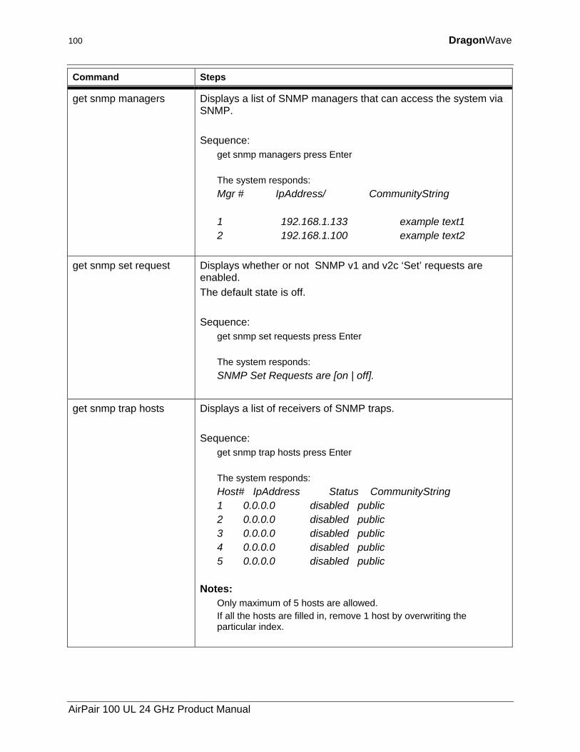
100 DragonWave
Command Steps
get snmp managers Displays a list of SNMP managers that can access the system via SNMP. Sequence:
get snmp managers press Enter The system responds: Mgr # IpAddress/ CommunityString 1 192.168.1.133 example text1 2 192.168.1.100 example text2
get snmp set request Displays whether or not SNMP v1 and v2c ‘Set’ requests are enabled. The default state is off. Sequence:
get snmp set requests press Enter The system responds: SNMP Set Requests are [on | off].
get snmp trap hosts Displays a list of receivers of SNMP traps. Sequence:
get snmp trap hosts press Enter The system responds: Host# IpAddress Status CommunityString 1 0.0.0.0 disabled public 2 0.0.0.0 disabled public 3 0.0.0.0 disabled public 4 0.0.0.0 disabled public 5 0.0.0.0 disabled public
Notes: Only maximum of 5 hosts are allowed. If all the hosts are filled in, remove 1 host by overwriting the particular index.
AirPair 100 UL 24 GHz Product Manual
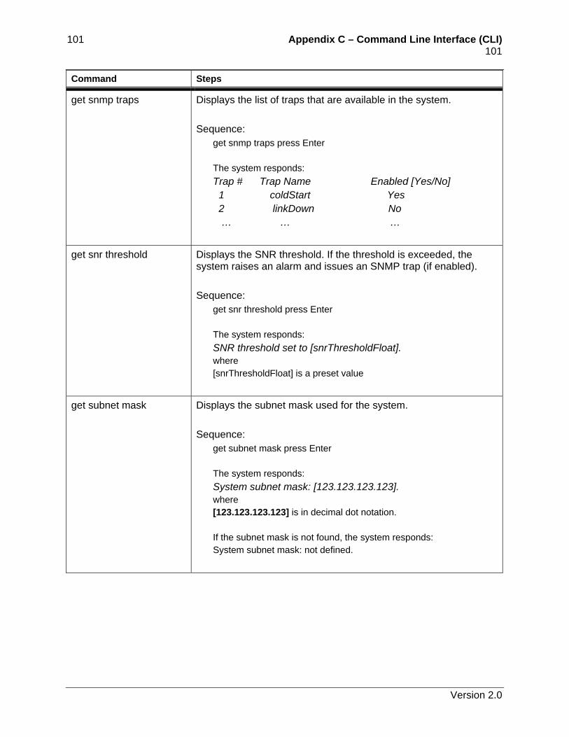
101 Appendix C – Command Line Interface (CLI) 101 Command Steps
get snmp traps Displays the list of traps that are available in the system. Sequence:
get snmp traps press Enter The system responds: Trap # Trap Name Enabled [Yes/No] 1 coldStart Yes 2 linkDown No … … …
get snr threshold Displays the SNR threshold. If the threshold is exceeded, the system raises an alarm and issues an SNMP trap (if enabled). Sequence:
get snr threshold press Enter The system responds: SNR threshold set to [snrThresholdFloat]. where [snrThresholdFloat] is a preset value
get subnet mask Displays the subnet mask used for the system. Sequence:
get subnet mask press Enter The system responds: System subnet mask: [123.123.123.123]. where [123.123.123.123] is in decimal dot notation. If the subnet mask is not found, the system responds: System subnet mask: not defined.
Version 2.0
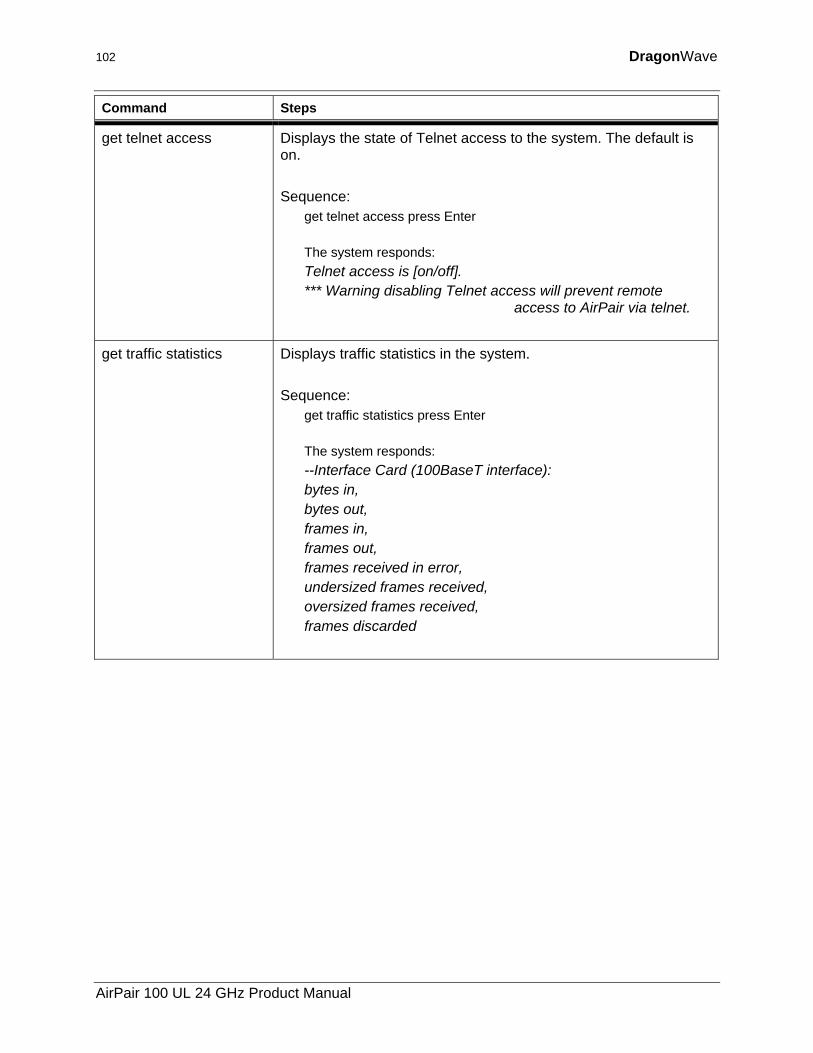
102 DragonWave
Command Steps
get telnet access Displays the state of Telnet access to the system. The default is on. Sequence:
get telnet access press Enter The system responds: Telnet access is [on/off]. *** Warning disabling Telnet access will prevent remote
access to AirPair via telnet.
get traffic statistics Displays traffic statistics in the system. Sequence:
get traffic statistics press Enter The system responds: --Interface Card (100BaseT interface): bytes in, bytes out, frames in, frames out, frames received in error, undersized frames received, oversized frames received, frames discarded
AirPair 100 UL 24 GHz Product Manual
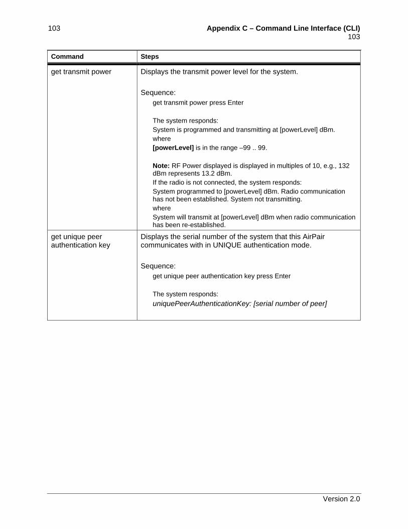
103 Appendix C – Command Line Interface (CLI) 103 Command Steps
get transmit power Displays the transmit power level for the system. Sequence:
get transmit power press Enter The system responds: System is programmed and transmitting at [powerLevel] dBm. where [powerLevel] is in the range –99 .. 99. Note: RF Power displayed is displayed in multiples of 10, e.g., 132 dBm represents 13.2 dBm. If the radio is not connected, the system responds: System programmed to [powerLevel] dBm. Radio communication has not been established. System not transmitting. where System will transmit at [powerLevel] dBm when radio communication has been re-established.
get unique peer authentication key
Displays the serial number of the system that this AirPair communicates with in UNIQUE authentication mode. Sequence:
get unique peer authentication key press Enter The system responds: uniquePeerAuthenticationKey: [serial number of peer]
Version 2.0
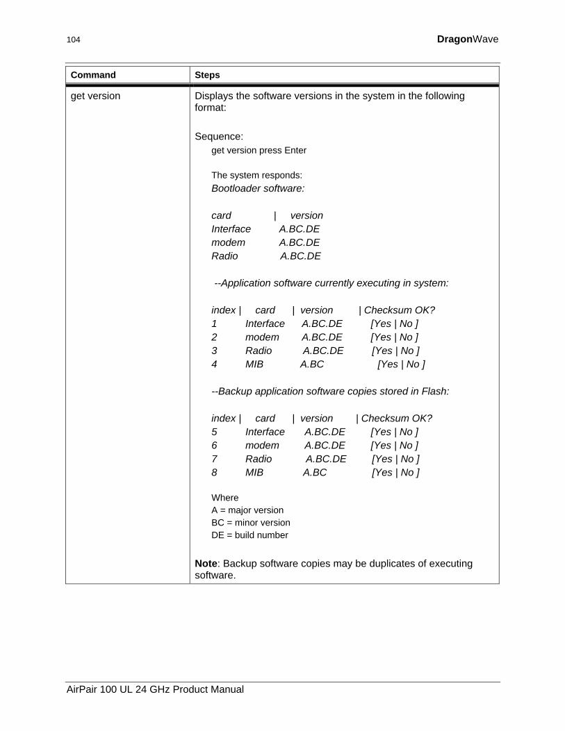
104 DragonWave
Command Steps
get version Displays the software versions in the system in the following format: Sequence:
get version press Enter The system responds: Bootloader software: card | version Interface A.BC.DE modem A.BC.DE Radio A.BC.DE --Application software currently executing in system: index | card | version | Checksum OK? 1 Interface A.BC.DE [Yes | No ] 2 modem A.BC.DE [Yes | No ] 3 Radio A.BC.DE [Yes | No ] 4 MIB A.BC [Yes | No ] --Backup application software copies stored in Flash: index | card | version | Checksum OK? 5 Interface A.BC.DE [Yes | No ] 6 modem A.BC.DE [Yes | No ] 7 Radio A.BC.DE [Yes | No ] 8 MIB A.BC [Yes | No ] Where A = major version BC = minor version DE = build number
Note: Backup software copies may be duplicates of executing software.
AirPair 100 UL 24 GHz Product Manual
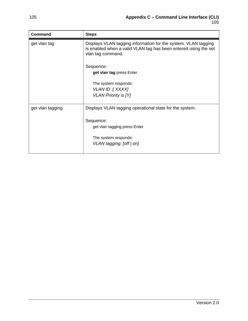
105 Appendix C – Command Line Interface (CLI) 105 Command Steps
get vlan tag Displays VLAN tagging information for the system. VLAN tagging is enabled when a valid VLAN tag has been entered using the set vlan tag command. Sequence:
get vlan tag press Enter The system responds: VLAN ID :[ XXXX] VLAN Priority is [Y]
get vlan tagging Displays VLAN tagging operational state for the system. Sequence:
get vlan tagging press Enter The system responds: VLAN tagging: [off | on]
Version 2.0
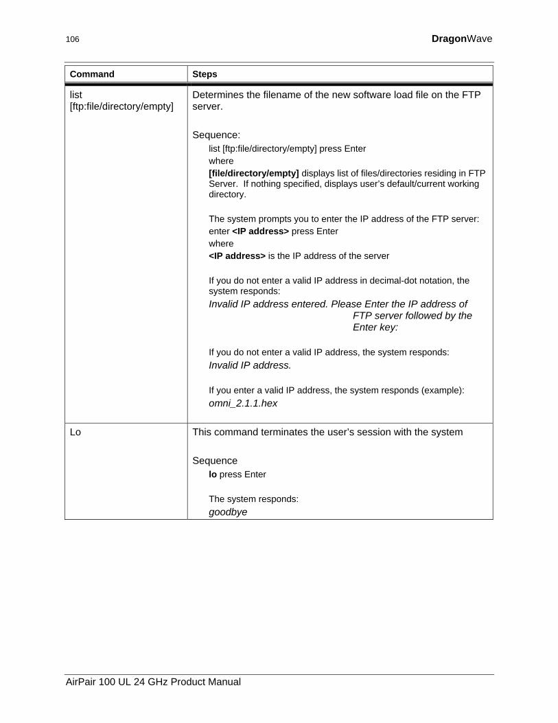
106 DragonWave
Command Steps
list [ftp:file/directory/empty]
Determines the filename of the new software load file on the FTP server. Sequence:
list [ftp:file/directory/empty] press Enter where [file/directory/empty] displays list of files/directories residing in FTP Server. If nothing specified, displays user’s default/current working directory. The system prompts you to enter the IP address of the FTP server: enter <IP address> press Enter where <IP address> is the IP address of the server If you do not enter a valid IP address in decimal-dot notation, the system responds: Invalid IP address entered. Please Enter the IP address of
FTP server followed by the Enter key:
If you do not enter a valid IP address, the system responds: Invalid IP address. If you enter a valid IP address, the system responds (example): omni_2.1.1.hex
Lo This command terminates the user’s session with the system Sequence
lo press Enter The system responds: goodbye
AirPair 100 UL 24 GHz Product Manual
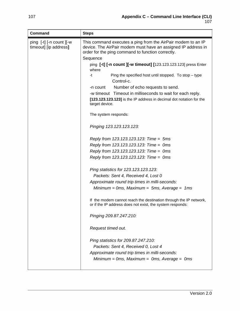
107 Appendix C – Command Line Interface (CLI) 107 Command Steps
ping [-t] [-n count ][-w timeout] [ip address]
This command executes a ping from the AirPair modem to an IP device. The AirPair modem must have an assigned IP address in order for the ping command to function correctly. Sequence
ping [-t] [-n count ][-w timeout] [123.123.123.123] press Enter where -t Ping the specified host until stopped. To stop – type
Control-c. -n count Number of echo requests to send. -w timeout Timeout in milliseconds to wait for each reply. [123.123.123.123] is the IP address in decimal dot notation for the target device. The system responds:
Pinging 123.123.123.123: Reply from 123.123.123.123: Time = 5ms Reply from 123.123.123.123: Time = 0ms Reply from 123.123.123.123: Time = 0ms Reply from 123.123.123.123: Time = 0ms Ping statistics for 123.123.123.123: Packets: Sent 4, Received 4, Lost 0 Approximate round trip times in milli-seconds: Minimum = 0ms, Maximum = 5ms, Average = 1ms
If the modem cannot reach the destination through the IP network, or if the IP address does not exist, the system responds: Pinging 209.87.247.210: Request timed out. Ping statistics for 209.87.247.210: Packets: Sent 4, Received 0, Lost 4 Approximate round trip times in milli-seconds: Minimum = 0ms, Maximum = 0ms, Average = 0ms
Version 2.0
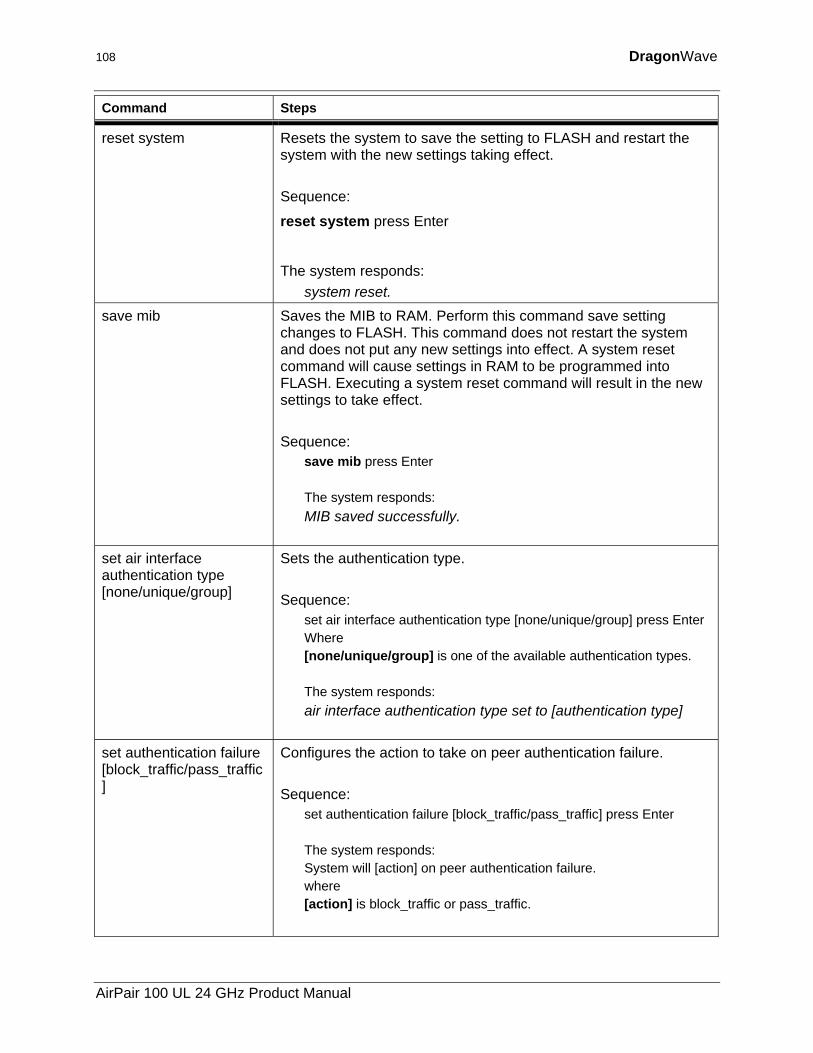
108 DragonWave
Command Steps
reset system Resets the system to save the setting to FLASH and restart the system with the new settings taking effect. Sequence:
reset system press Enter
The system responds: system reset.
save mib Saves the MIB to RAM. Perform this command save setting changes to FLASH. This command does not restart the system and does not put any new settings into effect. A system reset command will cause settings in RAM to be programmed into FLASH. Executing a system reset command will result in the new settings to take effect. Sequence:
save mib press Enter The system responds: MIB saved successfully.
set air interface authentication type [none/unique/group]
Sets the authentication type. Sequence:
set air interface authentication type [none/unique/group] press Enter Where [none/unique/group] is one of the available authentication types. The system responds: air interface authentication type set to [authentication type]
set authentication failure [block_traffic/pass_traffic]
Configures the action to take on peer authentication failure. Sequence:
set authentication failure [block_traffic/pass_traffic] press Enter The system responds: System will [action] on peer authentication failure. where [action] is block_traffic or pass_traffic.
AirPair 100 UL 24 GHz Product Manual
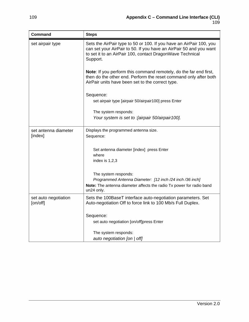
109 Appendix C – Command Line Interface (CLI) 109 Command Steps
set airpair type Sets the AirPair type to 50 or 100. If you have an AirPair 100, you can set your AirPair to 50. If you have an AirPair 50 and you want to set it to an AirPair 100, contact DragonWave Technical Support. Note: If you perform this command remotely, do the far end first, then do the other end. Perform the reset command only after both AirPair units have been set to the correct type. Sequence:
set airpair type [airpair 50/airpair100] press Enter The system responds: Your system is set to :[airpair 50/airpair100].
set antenna diameter [index]
Displays the programmed antenna size. Sequence:
Set antenna diameter [index] press Enter where index is 1,2,3
The system responds: Programmed Antenna Diameter: [12 inch /24 inch /36 inch]
Note: The antenna diameter affects the radio Tx power for radio band un24 only.
set auto negotiation [on/off]
Sets the 100BaseT interface auto-negotiation parameters. Set Auto-negotiation Off to force link to 100 Mb/s Full Duplex. Sequence:
set auto negotiation [on/off]press Enter The system responds: auto negotiation [on | off]
Version 2.0
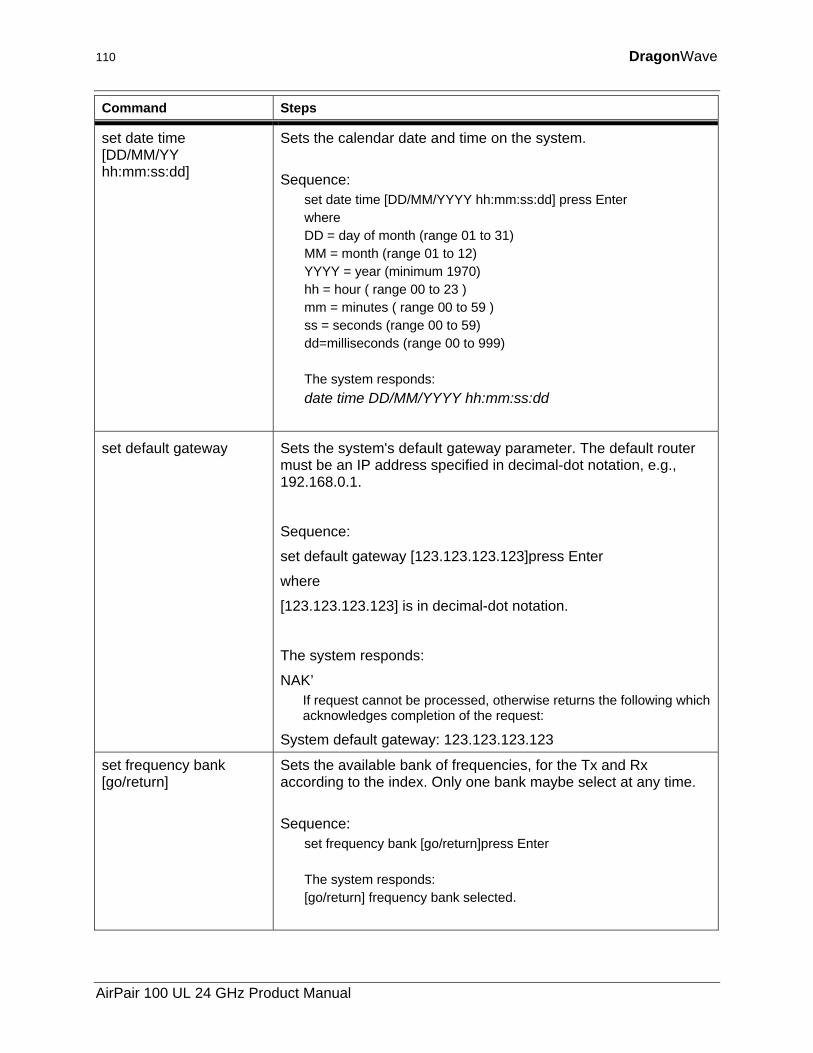
110 DragonWave
Command Steps
set date time [DD/MM/YY hh:mm:ss:dd]
Sets the calendar date and time on the system. Sequence:
set date time [DD/MM/YYYY hh:mm:ss:dd] press Enter where DD = day of month (range 01 to 31) MM = month (range 01 to 12) YYYY = year (minimum 1970) hh = hour ( range 00 to 23 ) mm = minutes ( range 00 to 59 ) ss = seconds (range 00 to 59) dd=milliseconds (range 00 to 999) The system responds: date time DD/MM/YYYY hh:mm:ss:dd
set default gateway Sets the system's default gateway parameter. The default router must be an IP address specified in decimal-dot notation, e.g., 192.168.0.1.
Sequence:
set default gateway [123.123.123.123]press Enter
where
[123.123.123.123] is in decimal-dot notation.
The system responds:
NAK’ If request cannot be processed, otherwise returns the following which acknowledges completion of the request:
System default gateway: 123.123.123.123
set frequency bank [go/return]
Sets the available bank of frequencies, for the Tx and Rx according to the index. Only one bank maybe select at any time. Sequence:
set frequency bank [go/return]press Enter The system responds: [go/return] frequency bank selected.
AirPair 100 UL 24 GHz Product Manual
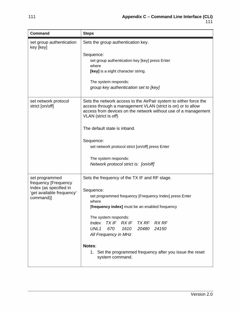
111 Appendix C – Command Line Interface (CLI) 111 Command Steps
set group authentication key [key]
Sets the group authentication key. Sequence:
set group authentication key [key] press Enter where [key] is a eight character string. The system responds: group key authentication set to [key]
set network protocol strict [on/off]
Sets the network access to the AirPair system to either force the access through a management VLAN (strict is on) or to allow access from devices on the network without use of a management VLAN (strict is off) The default state is inband. Sequence:
set network protocol strict [on/off] press Enter
The system responds: Network protocol strict is: [on/off]
set programmed frequency [Frequency Index (as specified in ‘get available frequency’ command)]
Sets the frequency of the TX IF and RF stage. Sequence:
set programmed frequency [Frequency Index] press Enter where [frequency index] must be an enabled frequency The system responds: Index TX IF RX IF TX RF RX RF UNL1 670 1610 20480 24150 All Frequency in MHz
Notes: 1. Set the programmed frequency after you issue the reset
system command.
Version 2.0
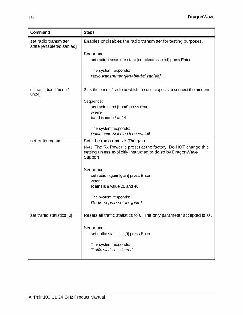
112 DragonWave
Command Steps
set radio transmitter state [enabled/disabled]
Enables or disables the radio transmitter for testing purposes. Sequence:
set radio transmitter state [enabled/disabled] press Enter The system responds: radio transmitter :[enabled/disabled]
set radio band [none / un24]
Sets the band of radio to which the user expects to connect the modem. Sequence:
set radio band [band] press Enter where band is none / un24 The system responds: Radio band Selected [none/un24].
set radio rxgain Sets the radio receive (Rx) gain. Note: The Rx Power is preset at the factory. Do NOT change this setting unless explicitly instructed to do so by DragonWave Support. Sequence:
set radio rxgain [gain] press Enter where [gain] is a value 20 and 40. The system responds: Radio rx gain set to [gain]
set traffic statistics [0] Resets all traffic statistics to 0. The only parameter accepted is ‘0’. Sequence:
set traffic statistics [0] press Enter The system responds: Traffic statistics cleared.
AirPair 100 UL 24 GHz Product Manual
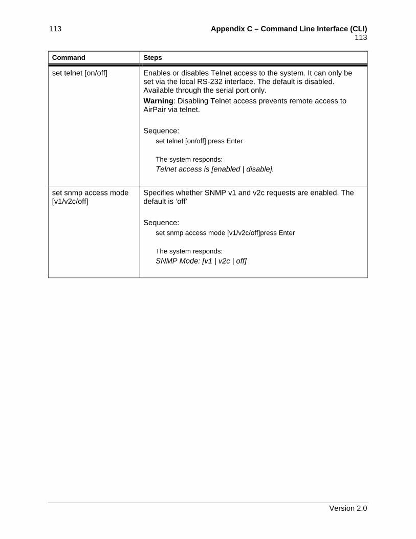
113 Appendix C – Command Line Interface (CLI) 113 Command Steps
set telnet [on/off] Enables or disables Telnet access to the system. It can only be set via the local RS-232 interface. The default is disabled. Available through the serial port only. Warning: Disabling Telnet access prevents remote access to AirPair via telnet. Sequence:
set telnet [on/off] press Enter The system responds: Telnet access is [enabled | disable].
set snmp access mode [v1/v2c/off]
Specifies whether SNMP v1 and v2c requests are enabled. The default is ‘off’ Sequence:
set snmp access mode [v1/v2c/off]press Enter The system responds: SNMP Mode: [v1 | v2c | off]
Version 2.0
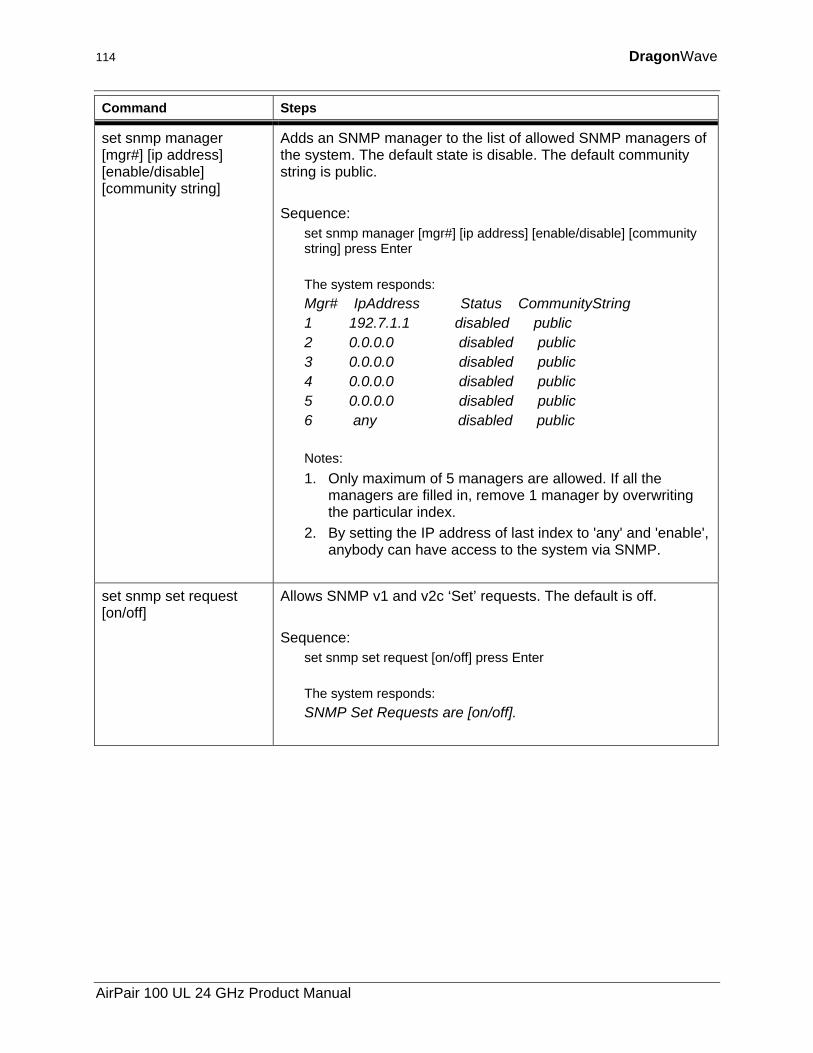
114 DragonWave
Command Steps
set snmp manager [mgr#] [ip address] [enable/disable] [community string]
Adds an SNMP manager to the list of allowed SNMP managers of the system. The default state is disable. The default community string is public. Sequence:
set snmp manager [mgr#] [ip address] [enable/disable] [community string] press Enter The system responds: Mgr# IpAddress Status CommunityString 1 192.7.1.1 disabled public 2 0.0.0.0 disabled public 3 0.0.0.0 disabled public 4 0.0.0.0 disabled public 5 0.0.0.0 disabled public 6 any disabled public Notes: 1. Only maximum of 5 managers are allowed. If all the
managers are filled in, remove 1 manager by overwriting the particular index.
2. By setting the IP address of last index to 'any' and 'enable', anybody can have access to the system via SNMP.
set snmp set request [on/off]
Allows SNMP v1 and v2c ‘Set’ requests. The default is off. Sequence:
set snmp set request [on/off] press Enter The system responds: SNMP Set Requests are [on/off].
AirPair 100 UL 24 GHz Product Manual
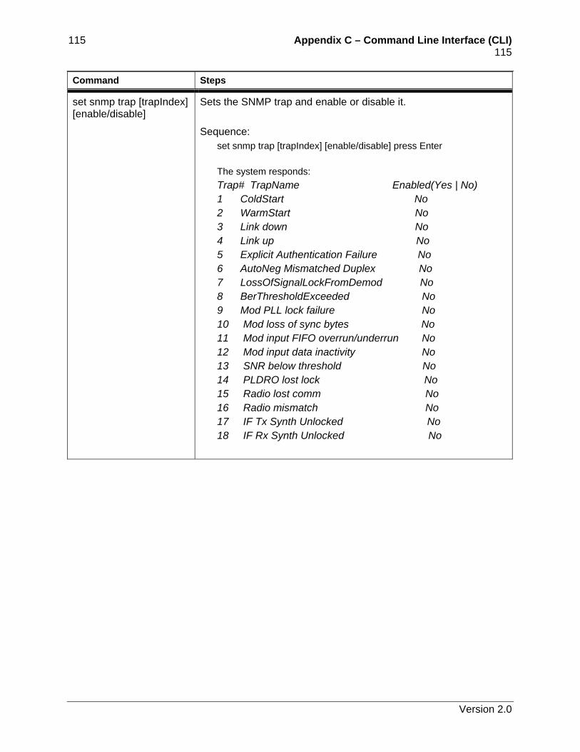
115 Appendix C – Command Line Interface (CLI) 115 Command Steps
set snmp trap [trapIndex] [enable/disable]
Sets the SNMP trap and enable or disable it. Sequence:
set snmp trap [trapIndex] [enable/disable] press Enter The system responds: Trap# TrapName Enabled(Yes | No) 1 ColdStart No 2 WarmStart No 3 Link down No 4 Link up No 5 Explicit Authentication Failure No 6 AutoNeg Mismatched Duplex No 7 LossOfSignalLockFromDemod No 8 BerThresholdExceeded No 9 Mod PLL lock failure No 10 Mod loss of sync bytes No 11 Mod input FIFO overrun/underrun No 12 Mod input data inactivity No 13 SNR below threshold No 14 PLDRO lost lock No 15 Radio lost comm No 16 Radio mismatch No 17 IF Tx Synth Unlocked No 18 IF Rx Synth Unlocked No
Version 2.0
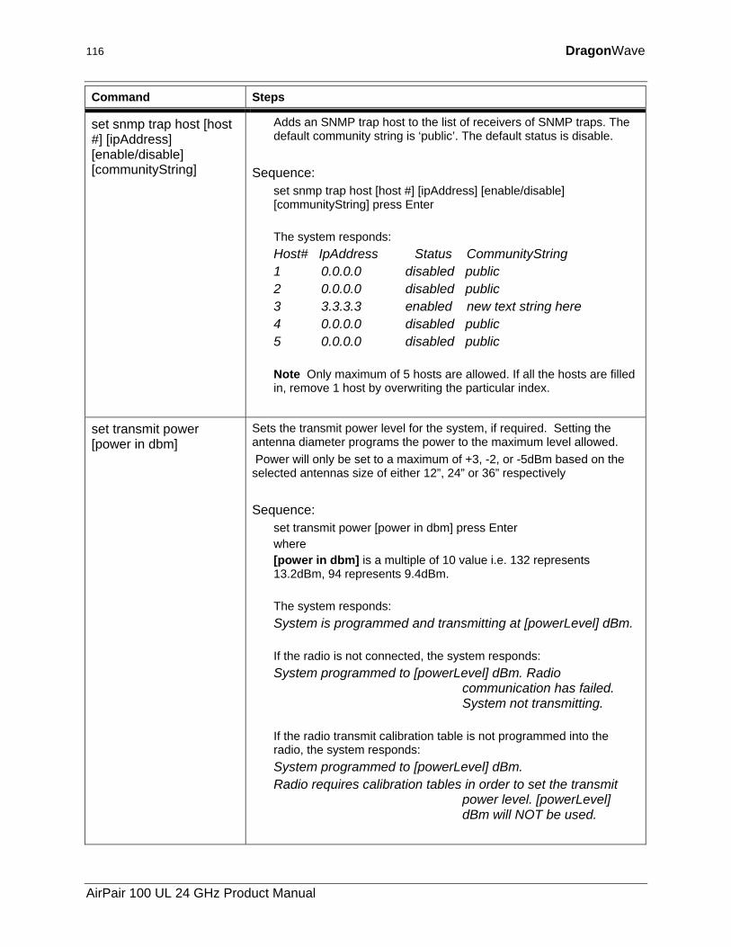
116 DragonWave
Command Steps
set snmp trap host [host #] [ipAddress] [enable/disable] [communityString]
Adds an SNMP trap host to the list of receivers of SNMP traps. The default community string is ‘public’. The default status is disable.
Sequence:
set snmp trap host [host #] [ipAddress] [enable/disable] [communityString] press Enter The system responds: Host# IpAddress Status CommunityString 1 0.0.0.0 disabled public 2 0.0.0.0 disabled public 3 3.3.3.3 enabled new text string here 4 0.0.0.0 disabled public 5 0.0.0.0 disabled public Note Only maximum of 5 hosts are allowed. If all the hosts are filled in, remove 1 host by overwriting the particular index.
set transmit power [power in dbm]
Sets the transmit power level for the system, if required. Setting the antenna diameter programs the power to the maximum level allowed. Power will only be set to a maximum of +3, -2, or -5dBm based on the selected antennas size of either 12”, 24” or 36” respectively Sequence:
set transmit power [power in dbm] press Enter where [power in dbm] is a multiple of 10 value i.e. 132 represents 13.2dBm, 94 represents 9.4dBm. The system responds: System is programmed and transmitting at [powerLevel] dBm. If the radio is not connected, the system responds: System programmed to [powerLevel] dBm. Radio
communication has failed. System not transmitting.
If the radio transmit calibration table is not programmed into the radio, the system responds: System programmed to [powerLevel] dBm. Radio requires calibration tables in order to set the transmit
power level. [powerLevel] dBm will NOT be used.
AirPair 100 UL 24 GHz Product Manual
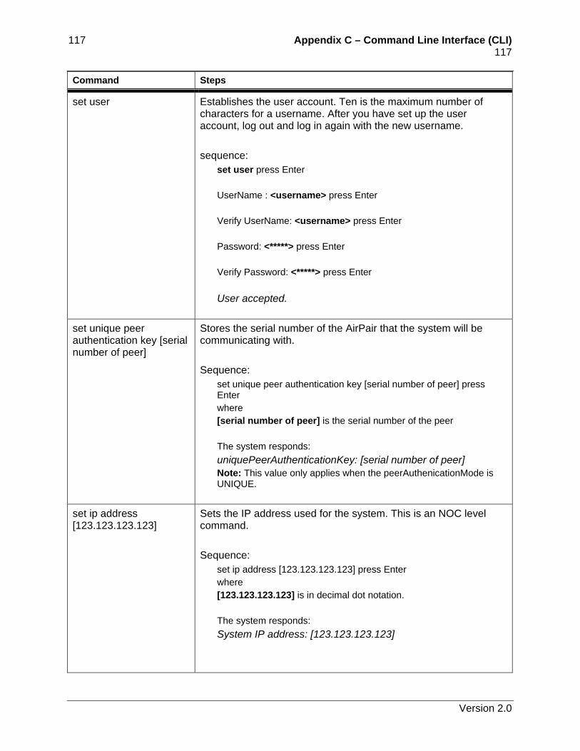
117 Appendix C – Command Line Interface (CLI) 117 Command Steps
set user Establishes the user account. Ten is the maximum number of characters for a username. After you have set up the user account, log out and log in again with the new username. sequence:
set user press Enter UserName : <username> press Enter Verify UserName: <username> press Enter Password: <*****> press Enter Verify Password: <*****> press Enter User accepted.
set unique peer authentication key [serial number of peer]
Stores the serial number of the AirPair that the system will be communicating with. Sequence:
set unique peer authentication key [serial number of peer] press Enter where [serial number of peer] is the serial number of the peer The system responds: uniquePeerAuthenticationKey: [serial number of peer] Note: This value only applies when the peerAuthenicationMode is UNIQUE.
set ip address [123.123.123.123]
Sets the IP address used for the system. This is an NOC level command. Sequence:
set ip address [123.123.123.123] press Enter where [123.123.123.123] is in decimal dot notation. The system responds: System IP address: [123.123.123.123]
Version 2.0
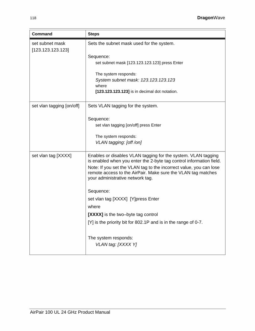
118 DragonWave
Command Steps
set subnet mask [123.123.123.123]
Sets the subnet mask used for the system. Sequence:
set subnet mask [123.123.123.123] press Enter The system responds: System subnet mask: 123.123.123.123 where [123.123.123.123] is in decimal dot notation.
set vlan tagging [on/off] Sets VLAN tagging for the system. Sequence:
set vlan tagging [on/off] press Enter The system responds: VLAN tagging: [off /on]
set vlan tag [XXXX] Enables or disables VLAN tagging for the system. VLAN tagging is enabled when you enter the 2-byte tag control information field. Note: If you set the VLAN tag to the incorrect value, you can lose remote access to the AirPair. Make sure the VLAN tag matches your administrative network tag. Sequence:
set vlan tag [XXXX] [Y]press Enter
where
[XXXX] is the two–byte tag control
[Y] is the priority bit for 802.1P and is in the range of 0-7.
The system responds: VLAN tag: [XXXX Y]
AirPair 100 UL 24 GHz Product Manual
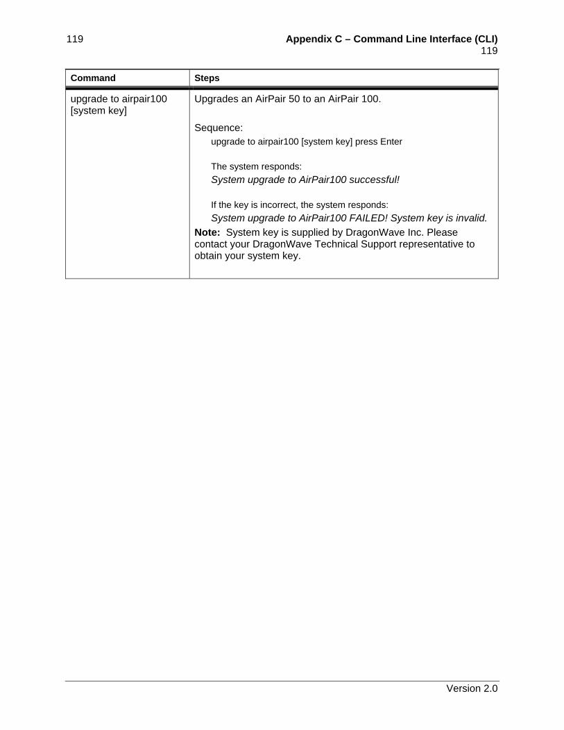
119 Appendix C – Command Line Interface (CLI) 119 Command Steps
upgrade to airpair100 [system key]
Upgrades an AirPair 50 to an AirPair 100. Sequence:
upgrade to airpair100 [system key] press Enter The system responds: System upgrade to AirPair100 successful! If the key is incorrect, the system responds: System upgrade to AirPair100 FAILED! System key is invalid.
Note: System key is supplied by DragonWave Inc. Please contact your DragonWave Technical Support representative to obtain your system key.
Version 2.0
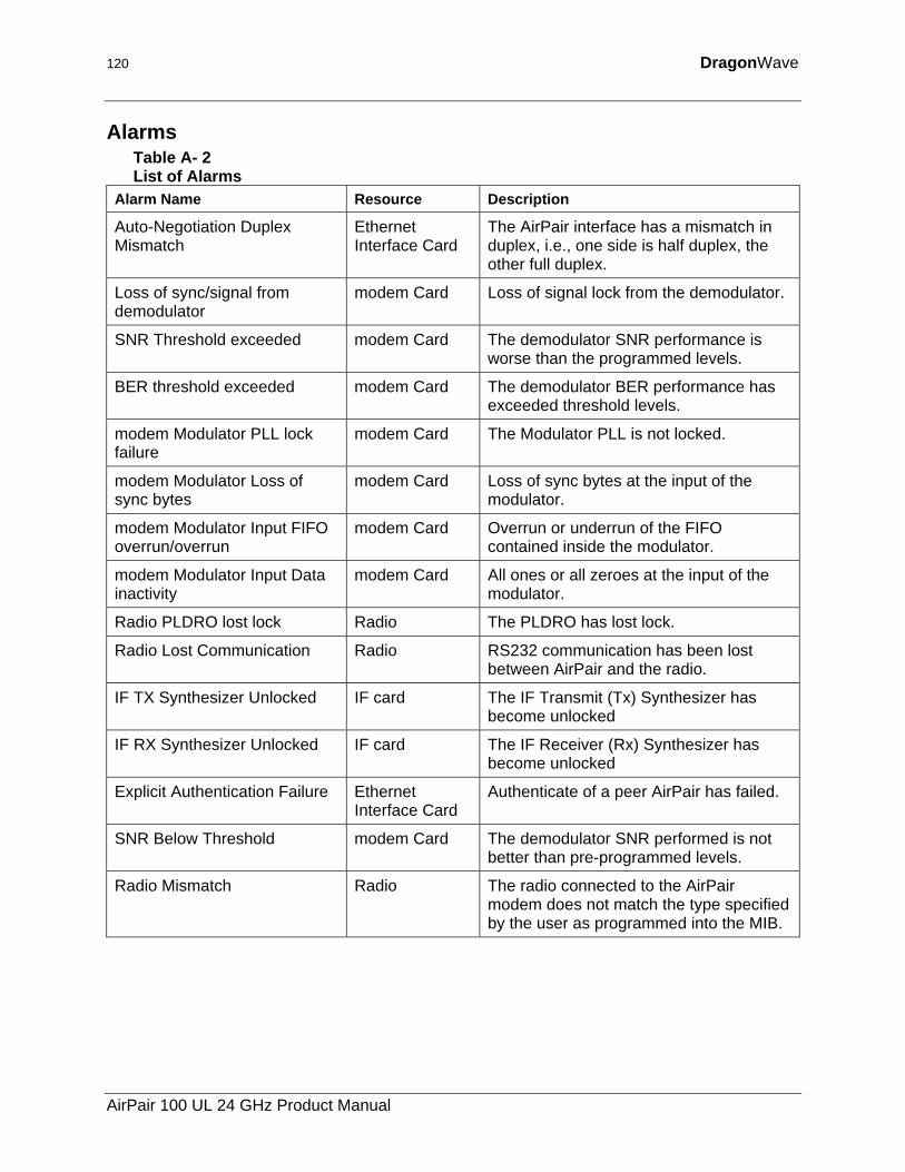
120 DragonWave
Alarms Table A- 2 List of Alarms
Alarm Name Resource Description
Auto-Negotiation Duplex Mismatch
Ethernet Interface Card
The AirPair interface has a mismatch in duplex, i.e., one side is half duplex, the other full duplex.
Loss of sync/signal from demodulator
modem Card Loss of signal lock from the demodulator.
SNR Threshold exceeded modem Card The demodulator SNR performance is worse than the programmed levels.
BER threshold exceeded modem Card The demodulator BER performance has exceeded threshold levels.
modem Modulator PLL lock failure
modem Card The Modulator PLL is not locked.
modem Modulator Loss of sync bytes
modem Card Loss of sync bytes at the input of the modulator.
modem Modulator Input FIFO overrun/overrun
modem Card Overrun or underrun of the FIFO contained inside the modulator.
modem Modulator Input Data inactivity
modem Card All ones or all zeroes at the input of the modulator.
Radio PLDRO lost lock Radio The PLDRO has lost lock.
Radio Lost Communication Radio RS232 communication has been lost between AirPair and the radio.
IF TX Synthesizer Unlocked IF card The IF Transmit (Tx) Synthesizer has become unlocked
IF RX Synthesizer Unlocked IF card The IF Receiver (Rx) Synthesizer has become unlocked
Explicit Authentication Failure Ethernet Interface Card
Authenticate of a peer AirPair has failed.
SNR Below Threshold modem Card The demodulator SNR performed is not better than pre-programmed levels.
Radio Mismatch Radio The radio connected to the AirPair modem does not match the type specified by the user as programmed into the MIB.
AirPair 100 UL 24 GHz Product Manual

121 Appendix C – Command Line Interface (CLI)
This page is intentionally left blank.
Version 2.0

Copyright © 2000-2003 DragonWave Inc. Printed in Canada. All rights reserved.
Visit us on the Internet at:
http://www.dragonwaveinc.com/