High-Brightness, High-Contrast, High-Performance DLP Projectors

High Brightness, High-average Power Picosecond Thin Disc Laser Program to
Specific Requirements from Short Wavelength Light Sources (S28)
Taisuke Miura, Michal Chyla, Martin Smrž, Patricie Severová, Ondřej Novák,
Akira Endo, and Tomáš Mocek The HiLASE project,
Institute of Physics, Prague
•HiLASE: High average power pulsed LASErs
•European project on strategic development of advanced solid-state laser technologies based on diode pumping (thin-disk laser, multi-slab laser)
•Potential for novel industrial applications using pulsed, high-energy & high-average power DPSSL
•Motivated by strong need for head-start laser technology development & prototyping for the next generation of high-energy, large scale laser facilities (ELI Beamlines, HiPER)
•Implementation phase: 09/2011- 08/2015
•Application phase: 2015-
Overview of The HiLASE Project

• Area of future R&D centres south of Prague city, enjoyable surroundings
• Synergy with ELI (on site) and biotechnology center BIOCEV (at 2 km distance)
• Fast connection (20 min.) to Ruzyne international airport
Location of The HiLASE Project

HiLASE team
PM T. Mocek
RP-1 A. Endo, T. Miura, M. Smrž, O. Novák, M. Chyla, P. Severová, Shiva Shankar. N
RP-2 A. Lucianetti, M. Divoký, O. Slezák, M. Sawicka, P. Sikocinski, V. Jambunathan, J. Pilař, V. Kmetík
RP-3 D. Rostohar, J. Vanda, L. Gemini, R. Švábek, Ch. Liberatore
Technical sup. M. Řeháková, V. Červenka, L. Švandrlík, J. Kadlec, H. Vohníková Admin. sup. L. Masopust, I. Vrbová, J. Svojšová, V. Svoboda, M. Vanková, J. Kavanová, J. Černý, R. Tůma, R. Kozáková, R. Karešová 10 / 2012 36 staff 08 / 2015 55 FTE 50% of our research staff is from abroad.

• HiLASE Research Program 1 (Thin disk laser) • Development of multi-J, kW class ps thin-disk laser system
• Mainly focused on medial and industrial applications
• Three beam lines with different beam parameters
• HiLASE Research Program 2 (Multi slab laser) • Development of 100 J / 10 Hz cryogenically cooled multi-slab ns
DPSSL system scalable to kJ level
• Applications: Laser-induced damage threshold test (LIDT),
Laser peening, Pumping source of OPCPA in the ELI project
• HiLASE Research Program 3 (Applications) • Using RA1 and RA2 lasers for industrial applications
• Applications:
EUV(13.5 nm) and Beyond-EUV(6.x nm) light source based on
laser-induced plasma,
Short pulse X-ray sources based on laser-Compton scattering
for biomedical imaging
LIDT and Laser peening
Project Activities of the HiLASE

Beam Lines of RP1
Beam
Line-C
Beam
Line-B
Beam
Line-A
Regenerative
amplifier
Booster
amplifier
Pulse compressor
1 J, 1-2 ps, 1 kHz
Oscillator
Pulse stretcher
Regenerative
amplifier
Pulse compressor
Oscillator
Pulse stretcher
5 mJ, 1-2ps, 100 kHz
Regenerative
amplifier
Ring amplifier
Pulse compressor
0.5 J, 1-2 ps, 1 kHz
Oscillator
Pulse stretcher
Sub-contract In-house development
500W, High energy
500W, High rep. rate
Priority issues of beam line B & C •High beam quality •High reliability •Small footprint •Cost effective

Industrial and Medical Applications Using High Energy Picosecond Pulse
Material
processing
Higher harmonics generation
Compton X-ray source
EUV
metrology
source
MID-IR pulse generation

Pre-pulse Laser for High Volume Machine EUV/BEUV Lithography
• Solid-state laser
• 3.3 mJ • 150 kHz • (500 W) • <10 ps
Pre pulse laser
CO2 lasers
1-kW EUV source

6.Xnm Beyond EUV (BEUV) Source
Sn plasma & Mo/Si @ 13.5 nm
ArF laser @ 193 nm
? & ? @ ? nm
For laboratory use: • Solid-state laser • 100-200 mJ • 1 kHz • 1-100 ps

In-line Phase Contrast Imaging of A Biological Specimen
Exposure time: 1800 sec
0.5-1 J, 1 ps pulse

Focusing Property of Driving Laser for EUV, BEUV, X-ray Pulse Generation
13 Feb. 2012
Target size: 10mm
Focal length of lens: f=100mm
•D=20mm
M2<1.5
•D=30mm
M2<2.3
•D=40mm
M2<3 0
5
10
15
20
25
30
1 1.5 2 2.5 3 3.5 4
Sp
ot D
iam
ete
r (1
/e2)
[mm
]
M2
f: 100mm, D: 20mm
f: 100mm, D: 30mm
f: 100mm, D: 40mm
Target size: f10mm

High Energy Picosecond Pulse Sources
[1] T. Metzger et. al., Opt. Lett. 34, pp. 2123 (2009).
[2] H. Stiel et. al., PTB Seminar EUV Metrology (2011).
[3] R. Jung et. al., Disklaser Workshop (2012).
[4] M. Schulz et. al., Opt. Express 20, pp. 5038 (2012).
[5] M. Schulz et. al., Opt. Lett. 36, pp. 2456 (2011).
Dual
Thin disk
Regen.
(MPQ, 2012)
Single
Thin disk
Regen.[1]
(MPQ, 2009)
Single
Thin disk
Regen.[2]
(MBI, 2011)
Single
Thin disk
Multi-pass[3]
(MBI, 2012)
Single
Thin disk
Multi-pass[4]
(DESY, 2012)
Innoslab[5]
(DESY, 2011)
Innoslab[5]
(DESY, 2011)
Repetition rate [Hz] 1,000,000 3,000 150 100 10 12,500 100,000
(100kHz burst)
Pulse energy [mJ] 0.23 25 305 548 3560 20 2
(80 pulses)
Average output [W] 230 75 45.8 54.8 35.6 250 200
Pump energy [J] CW 0.1 3.8 6.0 16.1 CW CW
Pump power [W] 600 280 562.5 600 161.2 600 600
O-O Efficiency [%] 38.3% 26.8% 8.1% 9.1% 22.1% 41.7% 33.3%
High energy + High average power = Challenging

Scaling Method of Thin Disk Laser for Fundamental-Mode Operation
0
0.1
0.2
0.3
0.4
0.5
0.6
0.7
0.8
1 2 3 4 5 6 7 8
0
1
2
3
4
5
6
7
8
2 3 4 5 6 7 8 9 10
Am
plif
ied p
uls
e f
luen
ce [J/c
m2]
Pu
mp
pow
er
den
sity [kW
/cm
2]
Cavity mode diameter on thin disk [mm]
Pump beam diameter [mm]
Energy fluence of 3.3-mJ output [J/cm2]
Energy fluence of 5-mJ output [J/cm2]
Damage threshold of 90-ps pulse [J/cm2]
Pump power density (O-O eff.=50%) [kW/cm2]
Typical limit of pump power density due to thermal stress [kW/cm2]
Pump power density (O-O eff.=30%) [kW/cm2]
Optical loss from Pockels cell etc.
Large diameter thin disk Degradation of beam
quality due to higher order
optical phase distortion
Beamline-C

Scaling Method of Thin Disk Laser for Fundamental-Mode Operation
0
1
2
3
4
5
4 5 6 7 8 9 10 11 12
0
1
2
3
4
5
6
7
8 6 8 10 12 14
Am
plif
ied p
uls
e flu
ence [J/c
m2]
Pu
mp
po
we
r d
en
sity [kW
/cm
2]
Cavity mode diameter on thin disk [mm]
Pump beam diameter [mm]
Energy fluence of 500-mJ output[J/cm2]
Damage threshold of 1.5-ns pulse [J/cm2]
Pump power density (O-O eff.=30%) [kW/cm2]
Pump power density (O-O eff.=13%) [kW/cm2]
Typical limit of pump power density due to thermal stress [kW/cm2]
Deterioration of O-O eff. via ASE
Beamline-B

Advantages of zero-phonon line pumping • Lower quantum defect
8.7 % @ 940 nm 5.9 % @ 969 nm
• Less heat generated in the gain medium Smaller deformation of thin disk Higher pump density
18 nm (FWHM@940 nm)
2.8 nm (FWHM@969 nm)
Improvement of O-O Efficiency via Zero-Phonon Line Pumping
96
9 n
m
(ex.)VBG (Volume Bragg Grating) installed narrowband laser diode

16
Beam Distortion Due to The Deformation of Large Size Thin Disk
Bifurcation of beam profile from thin disk multi-pass amplifier[2]
[1] R. Jung et. al., Disklaser Workshop (2012).
[2] A. Antognini et. al., IEEE J. Quantum Electron. 45, pp. 993 (2009).
The real time measurement of thin disk deformation is the key issue.

In-situ Measurement of Thin Disk Deformation Using Wavefront Sensor
Optical Table
Beam height: 125 mm
7-deg
Thin disk
Wavefront sensor
Probe source
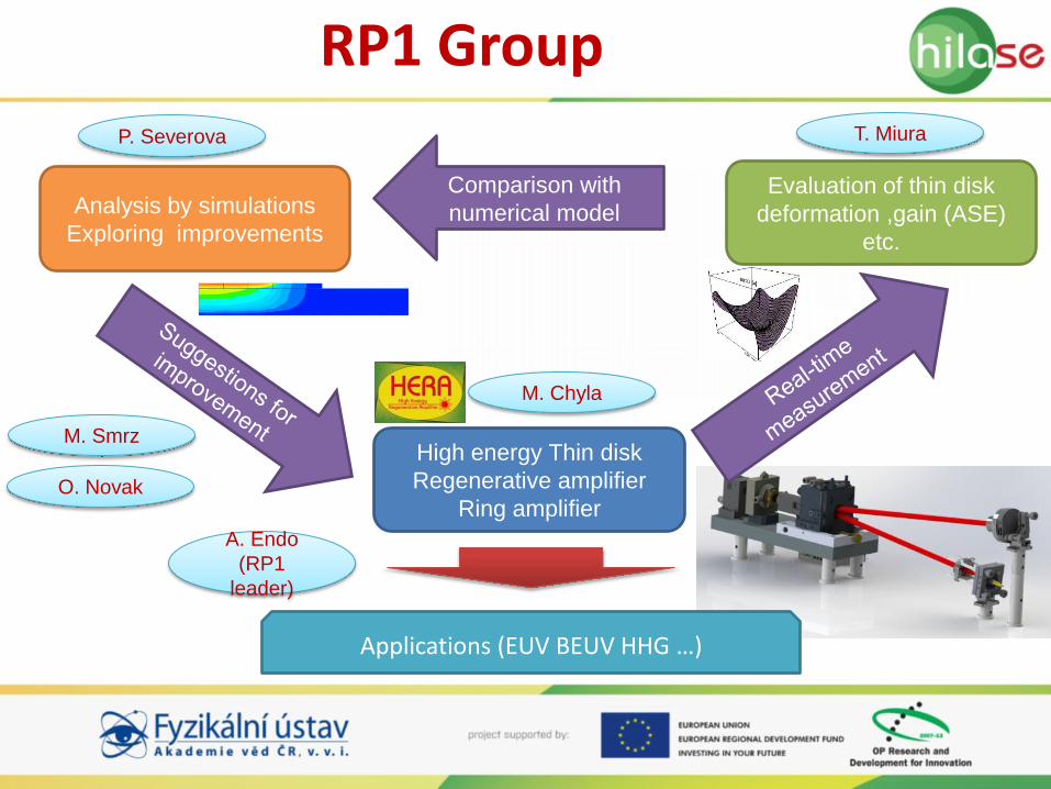
RP1 Group
High energy Thin disk
Regenerative amplifier
Ring amplifier
Applications (EUV BEUV HHG …)
Analysis by simulations
Exploring improvements
Evaluation of thin disk
deformation ,gain (ASE)
etc.
A. Endo
(RP1
leader)
M. Smrz
P. Severova
M. Chyla
T. Miura
Comparison with
numerical model
O. Novak

Fundamental Research Has Been Started
Seed pulse source Pulse Stretcher
<1M
Hz
Regenera
tive
am
plifie
r
<10kHz Regenerative
amplifier

Table-top High Power Laser Source in HiLASE
500W, 150kHz, 1-2 ps
Thin Disk Regenerative
Amplifier
Mode-locked
Fiber laser
CVBG
(Chirped Volume Bragg Grating)
l/4 l/4
l/2 PBS PBS
l/2
Thin disk head
Laser diode
Pockels cell
Thin disk meister (to be)

In-situ Measurement of Thin Disk Deformation
Wavefront from flat
mirror
Wavefront from concave
mirror (R=400mm)
Wavefront from thin disk

Preliminary Result of Thin Disk Deformation Measurement

• Introduction of the HiLASE Project
• Overview of the beam lines in RP1
• Design concepts of beam line B & C
• Preliminary result of thin disk deformation under the lasing operation
• High energy / high repetition rate amplifiers are under the construction
– End of this year
• 100mJ, 1kHz, 1-2ps
• 1mJ, 100kHz, 1-2ps
Summary