High-Bandwidth Tactical-Network Data Analysis in a … · ARL-TR-7412 SEP 2015 . US Army Research...
32
ARL-TR-7412 ● SEP 2015 US Army Research Laboratory High-Bandwidth Tactical-Network Data Analysis in a High-Performance-Computing (HPC) Environment: Voice Call Analysis by Kenneth D Renard, Greg M Besack, and Douglas F Dixon Approved for public release; distribution is unlimited.
-
Upload
phunghuong -
Category
Documents
-
view
215 -
download
0
Transcript of High-Bandwidth Tactical-Network Data Analysis in a … · ARL-TR-7412 SEP 2015 . US Army Research...
ARL-TR-7412 ● SEP 2015
US Army Research Laboratory
High-Bandwidth Tactical-Network Data Analysis in a High-Performance-Computing (HPC) Environment: Voice Call Analysis
by Kenneth D Renard, Greg M Besack, and Douglas F Dixon Approved for public release; distribution is unlimited.

NOTICES
Disclaimers
The findings in this report are not to be construed as an official Department of the Army position unless so designated by other authorized documents. Citation of manufacturer’s or trade names does not constitute an official endorsement or approval of the use thereof. Destroy this report when it is no longer needed. Do not return it to the originator.

ARL-TR-7412 ● SEP 2015
US Army Research Laboratory
High-Bandwidth Tactical-Network Data Analysis in a High-Performance-Computing (HPC) Environment: Voice Call Analysis
by Kenneth D Renard and Greg M Besack Computational and Information Sciences Directorate, ARL Douglas F Dixon Focused Ingenuity, Bel Air, MD Approved for public release; distribution is unlimited.
ii
REPORT DOCUMENTATION PAGE Form Approved OMB No. 0704-0188
Public reporting burden for this collection of information is estimated to average 1 hour per response, including the time for reviewing instructions, searching existing data sources, gathering and maintaining the data needed, and completing and reviewing the collection information Send comments regarding this burden estimate or any other aspect of this collection of information, including suggestions for reducing the burden, to Department of Defense, Washington Headquarters Services, Directorate for Information Operations and Reports (0704-0188), 1215 Jefferson Davis Highway, Suite 1204, Arlington, VA 22202-4302 Respondents should be aware that notwithstanding any other provision of law, no person shall be subject to any penalty for failing to comply with a collection of information if it does not display a currently valid OMB control number PLEASE DO NOT RETURN YOUR FORM TO THE ABOVE ADDRESS.
1. REPORT DATE (DD-MM-YYYY)
September 2015 2. REPORT TYPE
Final 3. DATES COVERED (From - To)
1 July 2012–31 December 2014 4. TITLE AND SUBTITLE
High-Bandwidth Tactical-Network Data Analysis in a High-Performance-Computing (HPC) Environment: Voice Call Analysis
5a. CONTRACT NUMBER
5b. GRANT NUMBER
5c. PROGRAM ELEMENT NUMBER
6. AUTHOR(S)
Kenneth D Renard, Greg M Besack, and Douglas F Dixon 5d. PROJECT NUMBER
5e. TASK NUMBER
5f. WORK UNIT NUMBER
7. PERFORMING ORGANIZATION NAME(S) AND ADDRESS(ES)
US Army Research Laboratory ATTN: RDRL-CIH-C Aberdeen Proving Ground, MD 21005-5067
8. PERFORMING ORGANIZATION REPORT NUMBER
ARL-TR-7412
9. SPONSORING/MONITORING AGENCY NAME(S) AND ADDRESS(ES)
10. SPONSOR/MONITOR'S ACRONYM(S)
11. SPONSOR/MONITOR'S REPORT NUMBER(S)
12. DISTRIBUTION/AVAILABILITY STATEMENT
Approved for public release; distribution is unlimited. 13. SUPPLEMENTARY NOTES 14. ABSTRACT
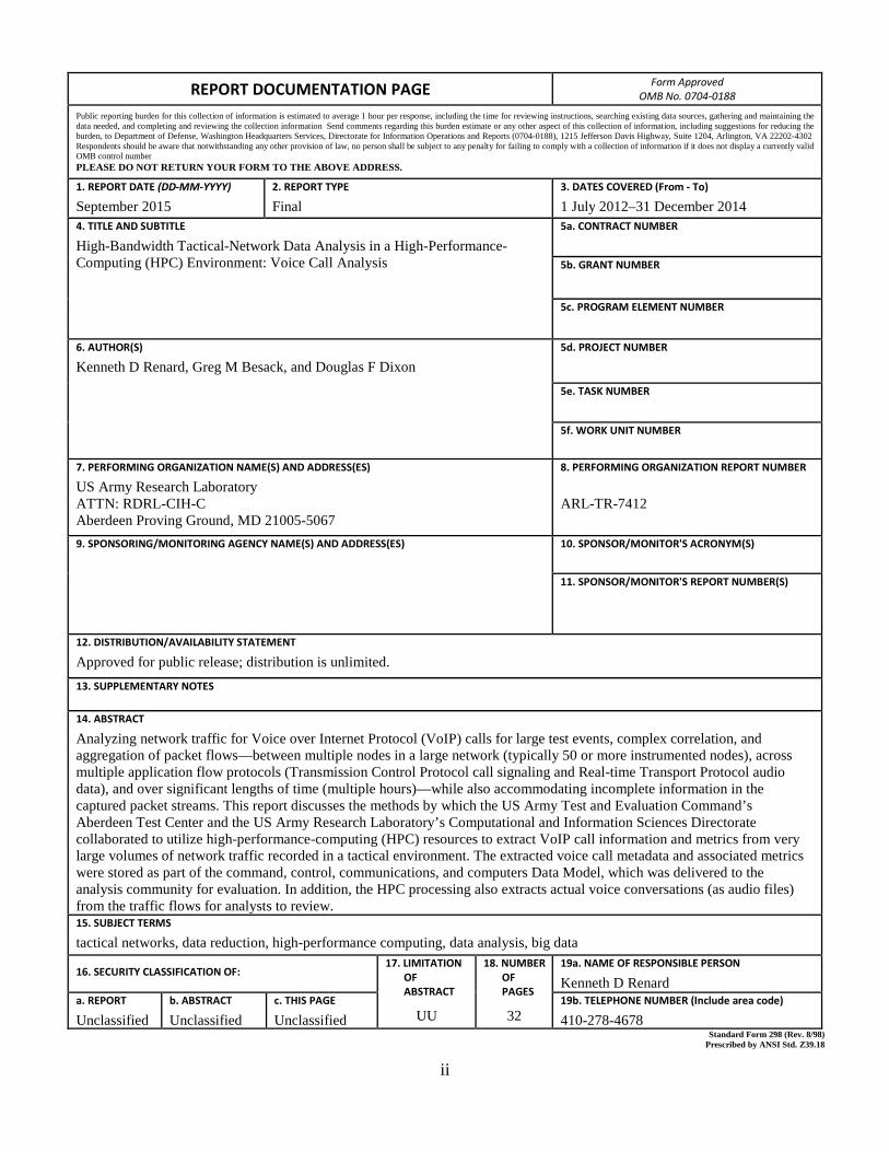
Analyzing network traffic for Voice over Internet Protocol (VoIP) calls for large test events, complex correlation, and aggregation of packet flows—between multiple nodes in a large network (typically 50 or more instrumented nodes), across multiple application flow protocols (Transmission Control Protocol call signaling and Real-time Transport Protocol audio data), and over significant lengths of time (multiple hours)—while also accommodating incomplete information in the captured packet streams. This report discusses the methods by which the US Army Test and Evaluation Command’s Aberdeen Test Center and the US Army Research Laboratory’s Computational and Information Sciences Directorate collaborated to utilize high-performance-computing (HPC) resources to extract VoIP call information and metrics from very large volumes of network traffic recorded in a tactical environment. The extracted voice call metadata and associated metrics were stored as part of the command, control, communications, and computers Data Model, which was delivered to the analysis community for evaluation. In addition, the HPC processing also extracts actual voice conversations (as audio files) from the traffic flows for analysts to review. 15. SUBJECT TERMS
tactical networks, data reduction, high-performance computing, data analysis, big data
16. SECURITY CLASSIFICATION OF: 17. LIMITATION OF ABSTRACT
UU
18. NUMBER OF PAGES
32
19a. NAME OF RESPONSIBLE PERSON
Kenneth D Renard a. REPORT
Unclassified b. ABSTRACT
Unclassified c. THIS PAGE
Unclassified 19b. TELEPHONE NUMBER (Include area code)
410-278-4678 Standard Form 298 (Rev. 8/98) Prescribed by ANSI Std. Z39.18

iii
Contents
List of Figures v
List of Tables v
1. Introduction 1
2. Voice Subsystem Components 1
3. Phone Equipment: Combat Network Radio Gateway 2
4. Voice Packet Flow: SIP, Session Description Protocol (SDP), and RTP 3
5. Voice Data Analysis 5
6. Call Analysis 6
7. Call Metrics 6
8. Data Model: Voice Tables 7
9. HPC VoIP Processing Overview 8
10. HPC Parallelization 8
11. HPC SIP Analysis 10
12. TCP to SIP: TCP Extract 11
13. TCP to SIP: TCP Conditioner 12
14. TCP to SIP: SIP Converter 12
15. SIP to Calls: SIP Manager 13

iv
16. SIP to Calls: SIP Sessions 14
17. SIP to Calls: RTP Parser 14
18. SIP to Calls: Complex Calls 15
19. Extracting Voice Audio from RTP 16
20. Recreating RTP Waveforms 17
21. Conclusion 18
22. References and Notes 20
List of Symbols, Abbreviations, and Acronyms 22
Distribution List 23

v
List of Figures
Fig. 1 Cisco IP phone .......................................................................................2
Fig. 2 Multi-Domain Atlas in Soldier Network Extension cab ........................2
Fig. 3 VoIP call flow ........................................................................................5
Fig. 4 HPC voice call processing flow .............................................................9
Fig. 5 Striping many unsorted TCP sessions to disk ......................................10
Fig. 6 TCP byte stream to SIP packet alignment ...........................................12
Fig. 7 SIP manager design overview ..............................................................13
Fig. 8 Illustration of the anchor as it shifts when calls are added ..................16
List of Tables
Table 1 Sample SIP messaging ...........................................................................4
Table 2 Sample SDP messaging .........................................................................4

vi
INTENTIONALLY LEFT BLANK.
1
1. Introduction
The Aberdeen Test Center/US Army Research Laboratory (ATC/ARL high-performance-computing (HPC) Voice over Internet Protocol (VoIP) call analysis processing is designed for a general VoIP system architecture based on Session Initiation Protocol (SIP) for negotiating call sessions and Real-time Transport Protocol (RTP) for transporting voice data packets.
The primary system under test has been the upper tactical internet assets within the US Army networking infrastructure, which is based on a Cisco Internet Protocol (IP) Telephony/VoIP system, as described in the following section. As a result, the VoIP analysis processing goes beyond the SIP standard to support the idiosyncrasies and extensions found in the tested Cisco implementations.
2. Voice Subsystem Components
The voice subsystem under test uses a commercial VoIP solution, based on the Cisco Unified Communications Manager (also known as the CallManager) and Cisco Unified IP Phone instruments.1 This commercial VoIP system employs standard IP networking for delivering the telephony signaling messages and voice conversation packets.
The voice subsystem is implemented as a standard VoIP solution, with IP-based telephone terminals that communicate over the local area network to their associated local VoIP server (CallManager). The CallManager servers maintain a local database with the administrative details of the VoIP phone network to be able to route calls to the appropriate destination device.
The telephone terminals provide the interface to the end user with dial pad, handset audio, and display. These plug in to the local network and connect to the associated local CallManager when the user dials a number. To set up the call, the local CallManager then forwards the call to the proper destination CallManager server for the dialed phone number, which then passes the phone call on to its local phone terminal registered for the number. Once the call is setup, the phone terminals then pass the voice data packets directly to each other over the network.
The Cisco VoIP system employs Skinny Client Control Protocol for network communication between the phone and the local CallManager (e.g., for each dialed digit), SIP between the endpoint CallManagers for call setup/termination signaling, and RTP for digitized voice transport.

2
3. Phone Equipment: Combat Network Radio Gateway
The VoIP system includes both VoIP hardphones (conventional physical phones) and softphones (software user interface implemented on the system display). The softphones are used in the vehicles, and the hardphones are typically used in shelters attached to stationary assets.
Hardphones like the Cisco Unified IP Phone are full-featured VoIP phones with a speakerphone and handset (Fig. 1). Softphones are implemented as an application on the system displays within vehicle cabs (Fig. 2), with a user interface that simulates the Cisco IP phone. The user speaks on the phone using the system headset, with earcups and a boom microphone.
Fig. 1 Cisco IP phone
Fig. 2 Multi-Domain Atlas in Soldier Network Extension cab
The vehicles also support a Combat Network Radio (CNR) gateway function, allowing the extension of analog voice radio networks, such as Single Channel Ground/Airborne Radio System and the Soldier Radio Waveform.
The CNR Gateway provides several usage scenarios to allow users on a vehicle's local radio network to converse with remote users over the wide area network (WAN) VoIP network:

3
• A VoIP caller can dial the dedicated CNR Gateway number for a vehicle, and the gateway will auto-answer the call and connect the caller into the vehicle's local radio network.
• The operator in the vehicle can use the gateway to dial out to an external number. When the call is connected, local users on the radio network can converse with the distant phone user (or with a group on a conference call).
• The operator in the vehicle can use the gateway to dial out to another gateway on a second vehicle. This bridges the local radio networks at each vehicle over the VoIP network so that the users can all communicate.
While CNR Gateway calls use very different equipment, to the VoIP system they simply appear to be normal voice calls that happen to dial from or into numbers associated with CNR Gateway equipment. From the point of view of the HPC reduction, these again look like normal calls, with SIP setup and RTP audio flow, although the details of the protocols can be different that that observed at the Cisco CallManagers.
The command, control, communications, and computers (C4) Data Model (C4_DM) then supports analysis of CNR Gateway calls separately from other call types by identifying CNR calls through the phone number and/or the phone device type.
4. Voice Packet Flow: SIP, Session Description Protocol (SDP), and RTP
The C4_DM Reduction process for VoIP calls supports VoIP traffic processing based on using SIP over Transmission Control Protocol (TCP) as the call signaling protocol (from call start to call termination), with the actual compressed voice bitstream carried on RTP over User Datagram Protocol (UDP). The local traffic between a phone and its CallManager is not used for analysis.
SIP is a simple application-level signaling communications protocol, widely used for controlling multimedia communication sessions, such as voice and video calls over IP networks. It is defined in ITEF RFC 3261.2
This protocol defines the messages that are sent between endpoints that govern establishment, termination, and other essential elements of a call consisting of one or more participants. SIP is designed as a session protocol to work independently of underlying transport protocols. It also can support other multimedia types and conferences.
4
SIP is implemented using a simple text-based protocol, stepping through session management using a request-response model (e.g., INVITE/OK to start call, BYE/OK to end it). SIP also uses a second set of numeric response codes (e.g., Ringing, Forwarded, Success, Redirection, Error) to respond to requests, provide status, indicate further action is required, and report errors. The 3-digit SIP Response code values are grouped with 3 levels of positive responses marking incremental call progress (1xx Informational, 2xx Success, 3xx Redirection), and 3 levels of error responses reporting call failure (4xx Client Failure, 5xx Server Failure, 6xx Global Failure).
These SIP codes are specified as literal text strings as shown in Table 1. The SIP protocol is used solely to negotiate the call session; the actual call parameters (including the phone numbers and audio encoding parameters) are embedded within the SIP messages using Session Description Protocol (SDP), as defined in ITEF RFC 4566.3 SDP is a standard representation for session description and media meta-data. The SDP is typically included in the SIP INVITE and OK messages to negotiate the media information to be used for the call.
Table 1 Sample SIP messaging
SIP Message Type Sample Message Text Request INVITE sip:[email protected] SIP/2.0
Response SIP/2.0 200 OK SDP also is a text-based format, using a simple <type>=<value> format. The actual options and values specified in the SDP traffic are dependent on the specific network and implementation, with session, time, and media description lines. Sample SDP messaging is shown in Table 2.
Table 2 Sample SDP messaging
SDP Message Type Sample SDP Message Session Originator and session identifier o=jdoe 2015554586 2015552877 IN IP4 10.0.0.2 Connection information c=IN IP4 224.0.1.1/127 Time Time session active t=2015557496 2015554696 Media Media name and transport m=audio 49170 RTP/AVP 0 Media attributes a=rtpmap:99 h263-1998/90000
In practice, the implementation of the SIP and SDP protocols observed in systems under test can be more complex than the notional handshaking described in the associated specifications. In particular, the INVITE message can be repeated a second time, from the receiver to the sender, and different information can be

repeated in the SDP portion of consecutive messages. The SDP flow also is used to communicate additional nonstandard infmmation, including call priorities, call transfer, and call conferencing infmmation. In other cases, some endpoint devices may not include important infom1ation in the SIP flow. The HPC code pe1fmming the processing of the VoiP call observables then must be capable of properly interpreting all of the expected variants of call setup and teardown and call
infmmation.
5. Voice Data Analysis
The Voice tables in the C4_DM are designed to directly suppmt the analysis of the flow of voice calls both by extracting call metadata and by computing common
metrics used for system requirements (e.g., completion, time to voice). The tables include the call endpoint infmmation, timestamps of key events in the call setup and voice traffic, and the fmal call disposition.
The VoiP Call Flow Diagram (Fig. 3) shows the logical call flow, from initiation to ringing to pickup to voice flow, and then to hang up. Tracking of the flow is driven by the SIP messaging request-response sequence, which signals key events in the call flow. The call timing metrics are based on the elapsed time between these events.
Call dialed
Elapsed Tune to Voice Clock time from last digit dialed
to near voice
VoiP Call Flow Initiator I Caller Receiver I Callee
~ * INVITE C-an Setup ffime to Ringl +-------T~ry~ing~ ~ Last digit dialed to phone rings
-<EE:--------"'R:;.,i!'!J.,_,iQQ,_ * ~ Phone ringing
'f' Woit for Pick Up (Off Hookl 1 Pbone riogs- to user lifts h&nd t
OK '+' .._ ______ .....;.;.;._ * .,...._ Pick up handset
~
t Pick Up to Voice Pick u;p to hear voice
Hear voice ~ * i==::::.-====~ * .,...._ Hearvoice +
BYE {Han!U!P}
Fig. 3 VoiP call flow
Call Time to Voice Dial to ring, plus pick up to voice (Elapsed time less wait for pick up)
The associated HPC voice processing supports this design by aggregating the packets containing the SIP messaging associated with a call, then parsing and extracting the call infmmation with the associated SDP infonnation. It also extracts
and analyzes the associated RTP flow in each direction, especially for packet delive1y metrics (e.g., loss, latency, and jitter).
5

6
6. Call Analysis
The approach used in creating the Voice tables in the C4_DM was to define the VoIP and metrics analysis in terms of a 3-step process:
1. Call Events: Record important events during the lifetime of each call (e.g., initiated, ringing, voice start, hang up), along with the associated timing.
2. Call Categorization: Categorize calls according to various characteristics useful in performing analysis (e.g., completed versus rejected versus error, simple versus complex).
3. Call Metrics: Compute metrics from the call results and timings, for useful clusters of calls based on the categorization.
This approach is intended to support broad system technical characterization and performance analysis, since a VoIP system cannot be usefully analyzed by simply performing gross calculations of call events and timings across all recorded calls. For example, if call completion is judged by a brute force count of only the number of calls that cause the end instrument to ring, then the calculation will be distorted by not accounting for busy calls, no answers, misdials, disconnected phones, or many other conditions that have nothing to do with measuring whether properly dialed calls are able to reach a properly connected destination.
7. Call Metrics
Call metrics are used to verify system performance against requirements and to evaluate performance improvements between system iterations. The HPC processing directly computes several system characterization metrics in the C4 Data Model Voice tables that are driven by system requirements. These also match metrics defined in ITU-T:E.425, Internal automatic observations (for checking the quality of the international telephone service).4
Based on the call events and categorizations, the following metrics are defined relative to the voice subsystem:
• Call Delivery Ratio (Call Completion Rate) metric
The Call Delivery Ratio metric is based on measuring calls for which the initial “Invite” message successfully transits the network to reach the destination instrument (i.e., Delivered event, which may include ringing, busy, or other cases). This initial delivery indication is independent of the further progress of the call. The ratio is then computed as the percentage of calls delivered compared with those

7
attempted, less calls categorized as “Invalid” or “No Test”. Defined as such, Call Delivery Ratio matches the Network Effectiveness Ratio definition in the ITU-T:E.425 standard.
• Call Delivery Delay (Time to Ring) metric
The Call Delivery Delay metric measures the time from the call’s initiated (last number dialed) to Delivered (ring) events. This metric applies to those calls included in the previously mentioned Call Delivery Ratio. Defined as such, this metric matches the Post Dialing Delay definition in the ITU E.437 standard.5
• Voice Setup Time (Time to Voice) metric
The Voice Setup Time metric measures the time from the call’s Initiated (dialed) to initial Voice Received (first voice) events, less the time from the Delivered (ring) to Accepted (pick up) events. Thus, this metric includes all voice system overhead between dialing and successful voice interchange but excludes the wait for the user to pick up a ringing call.
• Packet Delivery metrics (Loss, Latency, Jitter)
These standard metrics apply solely to the network’s performance in delivering the real-time stream of voice traffic contained within RTP packets. Within a point-to-point call, they are calculated and aggregated independently for each direction (i.e., caller-to-callee and callee-to-caller). Packet Loss represents the percentage of sent voice traffic packets that fail to successfully transit the network; Latency represents the average transit time of voice traffic packets successfully received; and Jitter represents the standard deviation of the individual voice traffic packet latencies.
8. Data Model: Voice Tables
The C4 Data Model6 contains 2 tables that focus on voice-related data and metrics:
• CommsVoiceCalls records metrics for each unique phone call.
• CommsVoiceFlows records metrics for the delivery of the real-time voice traffic stream.
The population of the tables employs the general process of identification of call events, categorization of calls based on context and type, and the subsequent computation of metrics based on the time-stamped events and category assignments.
The CommsVoiceCalls table includes a summary of all VoIP calls established via the SIP interchange between remote nodes; VoIP calls conducted locally to a given

8
node and application-specific VoIP are not included. As discussed earlier, the contents of the table tracks the call setup sequence, the establishment of the call, the transfer of digitized voice data, and call termination. Complex calls (e.g., call transfer, call forward, and conference call) are represented as multiple individual rows for each point-to-point connection.
The CommsVoiceFlows table includes statistics for RTP flows identified in the SIP traffic used to set up VoIP calls recorded in the CommsVoiceCalls table. It is used to collect call/packet statistics over discrete intervals of the call, including packet loss, latency, and jitter. The information for each call is broken into multiple records for each direction of the call flow (unique RTP SSRC [Synchronization Source]) and for each evaluation interval (“chunk”) within each voice call RTP traffic. The evaluation interval (chunk size) is nominally 15 s but can be shorter (especially at the end of a call).
One SIP call sequence (aggregated as a single entry in CommsVoiceCalls) is typically associated with a pair of RTP streams, one in each direction (stored in CommsVoiceFlows).
9. HPC VoIP Processing Overview
The HPC VoIP processing algorithms search, correlate, and aggregate SIP and RTP packet streams across all captured traffic on the network under test.
The processing begins with IP packet records stored in the CommsIP table.7 The process extracts and aggregates individual TCP sessions between SIP ports. It then parses and aggregates SIP message streams from the TCP sessions and parses the SIP messages and stores the information associated with each individual call. The IP packets are then processed to extract and aggregate the RTP flows associated with each call.
This processing can be complicated by the grouping of TCP streams with SIP sessions since one SIP call may bridge multiple TCP sessions.
10. HPC Parallelization
The HPC system permits this processing to be significantly accelerated by being performed in parallel, with parallel cores working independently on individual TCP sessions or SIP message streams. The overall flow of the processing of voice call data is shown in Fig. 4

9
Fig. 4 HPC voice call processing flow
The packet data being processed is stored in the HPC General Parallel File System,8 the centralized global file system accessible by all of the cores so that each core only needs to keep the data for the current session in local memory. The intermediate data, TCP sessions and SIP sessions, are accessed via a unique identification (ID), based on the TCP Transport ID or the SIP Call ID, respectively.
The Transport ID is the tuple of the TCP Source IP, Source Port, Destination IP, and Destination Port tuple, where the lower binary IP is sorted first along with its port. This collates both the initiator and receiver side of the TCP session into one hash, since the directionality is removed by the sort.
The SIP Call ID is used in the SIP protocol to uniquely identify a SIP Session. This is a pseudo-random sequence of alphanumeric characters that are guaranteed to be unique by the calling device (i.e., 29dce180-f519718-5-7d8ddb16 @12.345.678.123). This can be thought of as the key that all SIP packets are sorted by. Every SIP packet contains the SIP Call ID field. Calls will not span more than one Call ID, although they may span more than one TCP session.
The TCP and SIP sessions are assigned to processing cores using the hash of the TCP Transport ID or the SIP Call ID. Taking the hash modulo total ranks maps the

10
hash to a bin and its associated compute core. This distributes the work so that each core then can scan though the list of data to be processed and only process the elements whose hash matches the core number.
The intermediate output then is striped to disk to the associated bin file (Fig. 5). This is a single large file used to store the data for all the sessions that the core processes. This avoids the need to thrash the global file system by creating and accessing large numbers of small files.
Fig. 5 Striping many unsorted TCP sessions to disk
The Group Disk Cacher and Stream Reduce Manager modules each provide a file input/output API that manages local storage and transparently stripes data to the appropriate bin and reproduces the streams.
11. HPC SIP Analysis
The HPC processing of SIP messaging begins with searching the packet capture data for key elements of the call setup found within the SIP call signaling interchanges between the CallManagers.
This process results in the assignment of time stamps to each of the call setup events. From this information, the calls can be further categorized and overall call metrics can be computed.

11
The SIP messages include both SIP Request messages that initiate actions (e.g., Invite, ACK, Bye, Cancel) and numeric SIP Response codes that generally indicate whether the request succeeded or failed (e.g., 100 Trying, 180 Ringing, 183 Session Progress, 200 OK).
Voice call events are recorded in the CommsVoiceCalls table of the C4 Data Model. The associated fields capture the timestamp of each key step in the call setup (the SIP message interchange), including Initialized (i.e., SIP Invite Request message), Delivered (Ringing), Accepted (OK), and Hang Up (Bye), and timestamps from the associated RTP traffic, such as Start and Stop Time in each direction.
In addition, the CommsVoiceCalls table includes a CallEndReason field to report the disposition of the call, which is populated based on observed events. Specifically, if a SIP Bye is reached without encountering a SIP error, CallEndReason is set to BYE. Alternately, if a SIP error (i.e., codes 3xx, 4xx & 5xx) is found before a Bye, then the first such error event found is recorded in CallEndReason. Since it is possible for one call to have several different Bye and/or error messages in the SIP interchange, only the first such event is recorded (subsequent error messages are ignored by the reduction algorithms).
Observation of test data has shown that the Cisco implementation of SIP also can generate error messages after a call has successfully completed, and such errors also are ignored during reduction. Should an analyst need to see further call details, the HPC processing also reformats and outputs the packet capture data in packet capture (PCAP) files9 which can be used by several network packet capture tools such as Wireshark (www.wireshark.org).10
12. TCP to SIP: TCP Extract
The first step of the HPC VoIP processing is to aggregate TCP sessions to extract the SIP messaging (Fig. 4). Since the TCP VoIP module call metrics are heavily dependent on bidirectional communications, the module uses the output of the CommsIp module as its input, taking advantage of the packet matching done in this module, so that each packet record contains information from both the transmit and receive side observations.7 It applies a filter across all packets contained in CommsIp, matching any TCP packet on SIP source port 5060 or destination port 5060 (although some of these packets can be non-SIP).
To extract the call metadata from the SIP, the module performs basic TCP session reconstruction on the sessions filtered from CommsIp. The unrelated packets filtered from CommsIp are joined together into “streams” by using the Transport Hash.11

12
13. TCP to SIP: TCP Conditioner
After the unsorted SIP TCP packets are extracted, the TCP Conditioner reconstructs the TCP sessions, rebuilding the TCP streams as they were encountered on the transmitting/receiving CallManager. Since the conditioner has the luxury of examining the entire stream of packets, no “sliding window” logic is required to successfully reassemble the session, as the next arriving packet is already known. It is only necessary to properly align the TCP sequence and ACK numbers to accurately reproduce the TCP stream.
Out of order sequences also must be handled properly as they are critical to the arrival times of the packets at the application layer. That is, if a packet is lost in the stream and packets further along in the sequence are received, they will not be released to the app layer until the missing packet is also received and/or retransmitted.
14. TCP to SIP: SIP Converter
Once the TCP packets are reassembled into ordered logical TCP streams, they are fed into the SIP Converter. This module transforms the raw bytes in the TCP payload to discrete SIP messages.
The actual parsing of the byte stream into a discrete SIP message is handled by a portion of the SIPpy library.12 The SIPpy library is passed a chunk of the byte stream (Fig. 6) from which SIPpy creates a single packet in a greedy, left to right fashion, stopping when a packet is complete. This is repeated until the byte stream is entirely consumed. If SIPpy cannot produce a packet from the byte stream, the first “N” bytes are popped off the stream and the process is retried. This filters any corruption that may occur in the byte stream. Once the conversion from TCP to SIP is complete, the individual packets are passed into a SIP Manager processing module.
Fig. 6 TCP byte stream to SIP packet alignment

13
15. SIP to Calls: SIP Manager
The processing from SIP messages to SIP sessions (calls) uses a parser design with a tree hierarchy. A SIP Manager (Fig. 7) contains one or more SIP Sessions. A SIP Session contains one or more SIP Callers and one SipParser. As discussed previously, the SIP traffic is processed in parallel by SIP Call ID.
Fig. 7 SIP manager design overview
SIP Packets are fed into the SIP Manager one at a time. The SIP Manager creates new SIP Sessions based on the observance of a new SIP Call ID. The SIP Session creates a new SIP Caller based on the source IP address and direction of the packet (incoming or outgoing). This assigning of direction, or vectorization, of a packet is crucial to timing considerations for transmit and receive times of the packet, due to the multiple observations of the packet inherent to the distributed network testing.
Once the packets have been sorted into the proper SIP Caller in the SIP Session, an initial parse is called on in the SIP Caller to sort the SIP packets into message type categories such as INVITE, ACK, BYE, CANCEL, and all other 2xx, 3xx, 4xx, 5xx, and 6xx response categories. The SIP Caller also extracts and formats auxiliary information including SDP call information.

14
16. SIP to Calls: SIP Sessions
Once the SIP Caller has parsed all of its packets, the SIP Manager initiates the first round of parsing on all of its child SIP Sessions. This parse performs call type designation, voice traffic session parameter extraction, and many other call-timing functions.
In order to categorize the call type for further processing, a call is considered COMPLEX if a SUBSCRIBE type SIP message is observed in the SIP Caller parse. This necessitates further considerations discussed later. A call is designated INCOMPLETE if only one SIP Caller exists in the SIP Session. This is because of an instrumentation issue, since a call cannot possibly exist without a receiving device. A call is considered POINT-TO-POINT if the number of SIP Callers is exactly 2.
These classifiers only relate to the number of callers expected in a SIP Session. A SIP Session is then assigned either a PT-PT or COMPLEX parser, with INCOMPLETE receiving a PT-PT parser. A COMPLEX parser contains a PT-PT parser in addition to specific COMPLEX parsing routines mentioned later.
The PT-PT parser is designed to parse a call from the initiator and receiver points of view. Having both sides allows the parser to extract accurate timing information from the sequence of events that occur.
The SIP Session will call the parse routine on its parser. Events such as Canceled, Invalid, Error, and Dropped are all considered and handled here as well. The extracted parameters are attached to the SIP Session.
The Voice Traffic Session Parameters are extracted from the SDP components of some SIP messages. These include the sending and receiving Phone IP addresses, sending and receiving ports, and the time stamp of the SIP message indicating a successful call connection and the time stamp of the SIP message indicating the end of a call.
17. SIP to Calls: RTP Parser
The parser also searches for any RTP/UDP voice traffic sessions associated with the call (i.e., the actual packet traffic that contains encoded voice data). The call parameters are passed back to the main module to perform another search for any UDP/RTP through all CommsIp output, looking for packets that meets the criteria (IPa, IP2b, PORTa, PORTb, starttime, endtime). It is possible, although highly

15
unlikely, for other packets to match this exact signature. Should this occur, there is no factor to help overcome the ambiguity other than application layer analysis of the packet that is outside the scope of this parser.
Once the SIP Session has its RTP traffic loaded, it parses it for relevant statistics. It calculates packet flow statistics over 15-s windows (for the CommsVoiceFlows table), and computing statistics over the entire call. Appropriate considerations are made for one-sided packets (sent but not received, received but not sent) and malformed latency.
18. SIP to Calls: Complex Calls
The final step to the VoIP module is to parse out the links between COMPLEX calls. Again, a COMPLEX call is a call that has more than 2 participants at any time, TRANSFER, CONFERENCE (ad-hoc), or MEETME (central conference line). In the initial PARSE stage, each call is designated either PT-PT, INCOMPLETE, or COMPLEX. The COMPLEX calls are further parsed and designated one of the TRANSFER, CONFERENCE, or MEETME property. These calls are all offloaded to a single rank where the actual linking of the calls takes place.
The linking between 2 separate calls is based on a dynamic, temporal window bounded by the start and end times of a call. Every COMPLEX call in the list is sorted by call start time, earliest first. This call’s start and end times is the first “anchor point”. Anchor points define the time window (start and end) of a voice call. If the next call’s start time falls within the boundary of the anchor (i.e., anchor.start <= current.start <= anchor.end) then this call is considered “LINKED” and the 2 calls are assigned the same “AGGREGATE ID” (Fig. 8). Then the aggregate call anchor’s end time is expanded by the call with the latest end time, expanding the ANCHOR if necessary. If the next call’s start time falls outside of the ANCHOR, a new ANCHOR is created using the same next call as the initial parameters and a new AGGREGATE ID.

16
Fig. 8 Illustration of the anchor as it shifts when calls are added
19. Extracting Voice Audio from RTP
The collected raw packet data on the HPC contains both the TCP SIP call management traffic and the UDP/RTP flow containing the compressed voice bit streams transmitted in each direction. The HPC processing provides the option to extract the audio segments from RTP packets, and then aggregate, decompress, and save the transmitted voice streams (e.g., as uncompressed WAVE/PCM audio files).
Streams captured at the sender side then can be played back to review the voice quality of the transmitted audio, for example, to evaluate whether there is significant background noise or audio artifacts in the audio received from the headset.
Streams captured at the receiver side then should sound the same, as they are a digital packet stream of audio samples delivered over the network. The issue instead is whether the packets were received in a timely manner to permit them to be played back continuously or whether some packets were lost or arrived late, causing skips and gaps.

17
One option for the receiver side is to reassemble the audio stream as best as possible, ignoring these issues. This provides a basic sense of how the received audio could have been heard, including skips for lost packets.
Instead, the HPC voice packet analysis includes a packet buffering model that uses the arrival time information for each packet to simulate the result on the audio playback buffer. This includes introducing gaps for missing packets or packets that arrived too late. This provides a more accurate simulation of the user experience in listening to the received audio.
20. Recreating RTP Waveforms
Once the RTP is parsed out and linked back to the SIP Session, the HPC processing can perform the optional feature of rebuilding the actual waveform audio. This essentially replays the packets as observed from each device and produces 4 distinct streams: Inbound A, Outbound A, Inbound B, and Outbound B. These streams create the ability to hear the lossless stream from the sending device and the potentially lossy stream from the receiving side.
The WAN VoIP calls are typically encoded with the G.729 codec13 transported over an RTP stream. The VoIP decoder takes as input the raw RTP Payload values.
Recreating RTP waveforms from RTP packets presents an interesting design issue due to the minimal information in the RTP header. RTP provides timestamps for synchronization and sequence numbers for packet loss and reordering. However, the RFC for RTP designates a 16-bit sequence counter for RTP streams, similar to sequence numbers in TCP. Assuming a G.711 encoder with a sample rate of 8,000 samples per second, and 40 samples per packet, the counter will roll over every 327.68 s. Expanding on this, any call that lasts N>1 multiples of this rollover constant will have an ambiguity in the position of 2 packets with similar time stamps. In addition, the RTP timestamp field is not a reliable sorting member since the RFC allows this field to be null. Because of this, the RTP packets are binned by the sequence number first and then each bin is sorted by the appropriate transmit/receive time of the packet, depending on the packet direction. Finally, the bins are looped over, picking the first packet from each bin in sequence.
The possibility of missing sequence numbers is handled by checking the timestamp of the previously used sample against the current sample. If this delta is outside of a constant time threshold (50 s in this implementation), the packet is discarded and the next one checked. Should there be a reason that transmission was interrupted entirely for greater than 50 s, then the current packet is picked and the process of iterating over the bins continues.

18
To emulate audible gaps in the reconstructed waveform and produce a temporally synced call for both transmit and receive observation points, the rebuilt RTP stream can be artificially padded with null bytes (\x00) for any missing packets. The length of padding is implementation dependent and was empirically determined to be 40 bytes per missing packet.
This depends on detecting gaps in the sequence numbers. Since these numbers are serial in the sense that they are linearly increasing with each new packet, serial arithmetic must be used to account for any comparisons that span the rollover boundary.14 RFC-1982 defines the limits of performing binary comparisons on 2 “serial” numbers, specifically where the ambiguity lies.
Once the RTP payloads are reassembled and reserialized, each of the 4 streams (txout, txin, rxout, and rxin) are written to disk. The G.729 decoder converts them to the common RAW PCM wav file format, which can be played by any audio tool.
21. Conclusion
The depth of the VoIP system analysis performed by the ATC/ARL HPC Reduction process was demonstrated at the US Army Network Integration Exercise (NIE) 15.1.
The HPC system processed around 1.5 TB of raw data per day over the 19-day event, producing data in a steady stream for analysis in the form of 1.1 GB of databases containing 4.7 billion records per day.
Over the full NIE 15.1 event, the HPC processing analyzed over 58 billion raw packets, correlated 14 billion end-to-end IP packets, and aggregated 210 million TCP sessions, to extract over 42,000 VoIP phone calls and associated RTP audio.
For each of these calls, the HPC system assembled and parsed the SIP session messaging (and associated SDP information) to populate the VoiceCalls table in the Data Model with call information and performance metrics. The system also processed the associated RTP packets to populate the VoiceFlows table with call network performance metrics.
These Voice tables then provide analysts with the ability to review the voice call traffic across the network and examine its performance in relation to numerous VoIP and network variables.
In addition, the HPC system can optionally generate PCAP files for further analyst review with packet tools.

19
Beyond network analysis, the HPC system also provides the ability to extract and review the actual audio conversations carried in the RTP packet flow. In this way, analysts can compare sent versus received audio quality and hear the experience of the test users as they use the VoIP system.

20
22. References and Notes
1. Cisco. Cisco unified communications manager version 8.5 with 8.6 data sheet. Houston (TX): n.d. [accessed 2015 Jan 15]. http://www.cisco.com/c/en /us/products/collateral/unified-communications/7800-series-media -convergence-servers /data_sheet_c78-652908.html.
2. Rosenberg J, Schulzrinne H, Camarillo G, Johnston A, Peterson J, Sparks R, Handley M, School E. SIP: session initiation protocol; RFC 3261, 2002 June [accessed 2015 Jan 15]. http://www.rfc-editor.org/info/rfc3261. DOI 10.17487/RFC3261,
3. Handley M, Jacobson V, Perkins C. SDP: session description protocol; RFC 4566, 2006 July [accessed 2015 Jan 15]. http://www.rfc -editor.org/info/rfc4566. DOI 10.17487/RFC4566.
4. International Telecommunication Union. E.425 – Network management – checking the quality of the international telephone service: internal automatic observations. Geneva (Switzerland): ITU; 2002 Mar.
5. International Telecommunication Union. E.437 – Qualtiy of service, network management – checking the quality of the international telephone service: Comparative metrics for network performance management. Geneva (Switzerland): ITU; 1999 May.
6. Adametz J. C4 data model description document 1.8.13. Aberdeen Proving Ground (MD): Aberdeen Test Center; unpublished 2014.
7. Panneton B, Adametz J. High-bandwidth tactical-network data analysis in a high-performance-computing (HPC) environment: packet level analysis. Aberdeen Proving Ground (MD): Army Research Laboratory (US); 2015 Sep. Report No.: ARL-CR-0779.
8. IBM. General parallel file system. Armonk (NY): n.d. [accessed 2015 Jan 21]. http://www-03.ibm.com/software/products/en/software/.
9. Harris G. Libpcap file format. Wireshark.Org.; 2013 July 29 [accessed 2015 Jan 15]. http://wiki.wireshark.org/Development/LibpcapFileFormat.
10. Lamping U, Sharpe R, Warnicke E. Wireshark user’s guide. 2014 Nov 9. 29 [accessed 2015 Jan 15]. https://www.wireshark.org/docs/wsug _html_chunked/.
11. Renard K, Adametz J. High-bandwidth tactical-network data analysis in a high-performance-computing (HPC) environment: transport protocol
21
(transmission control protocol/user datagram protocol [TCP/UDP]) analysis. Aberdeen Proving Ground (MD): Army Research Laboratory (US); 2015 Sep. Report No.: ARL-TR-7411.
12. Sippy B2BUA, a RFC3261-compliant Session Initiation Protocol (SIP) back-to-back user agent (B2BUA) server software. 2012 [accessed 2014 Jan]. http://b2bua.org/.
13. International Telecommunications Union. G.729: coding of speech at 8 kbit/s using conjugate-structure algebraic-code-excited linear prediction (CS-ACELP); 2014 May 15 [accessed 2015 Jan 21]. http://www.itu.int/rec/T-REC -G.729/e.
14. Elz R, Bush R. Serial number arithmetic. RFC 1982, 1996 Aug [accessed 2014 Jan 22]. http://www.rfc-editor.org/info/rfc1982. DOI 10.17487/RFC1982.

22
List of Symbols, Abbreviations, and Acronyms
ARL US Army Research Laboratory
ATC US Army Aberdeen Test Center
CNR Combat Network Radio
HPC high-performance computing
ID identification
IP Internet Protcol
NIE Network Integration Exercise
PCAP packet capture
RTP Real-time Transport Protocol
SIP Session Initiation Protocol
SDP Session Description Protocol
TCP Transmission Control Protocol
UDP User Datagram Protocol
VoIP Voice over Internet Protocol
WAN wide area network

23
1 DEFENSE TECHNICAL (PDF) INFORMATION CTR DTIC OCA 2 DIRECTOR (PDF) US ARMY RESEARCH LAB RDRL CIO LL IMAL HRA MAIL & RECORDS MGMT 1 GOVT PRINTG OFC (PDF) A MALHOTRA 1 DIR USARL (PDF) RDRL CIH C K RENARD

24
INTENTIONALLY LEFT BLANK.