High Average Power Laser Program Workshop University of Wisconsin, Madison October 22-23, 2008...
22
High Average Power Laser Program Workshop University of Wisconsin, Madison October 22-23, 2008 Pulsed E-beam Thermofatigue System Chad E. Duty Materials Science & Technology Division Oak Ridge National Laboratory Helium Retention in Nano-Porous Tungsten Nalin Parik, R. Parker, J. Gladden University of North Carolina, Chapel Hill R. Downing, L. Cao National Institute of Standards and Technology Gaithersburg, MD QuickTime™ TIFF (Uncompre are needed to With a special appearance by the ghost of Jeff Latkowski
-
Upload
jeffery-newton -
Category
Documents
-
view
217 -
download
0
Transcript of High Average Power Laser Program Workshop University of Wisconsin, Madison October 22-23, 2008...
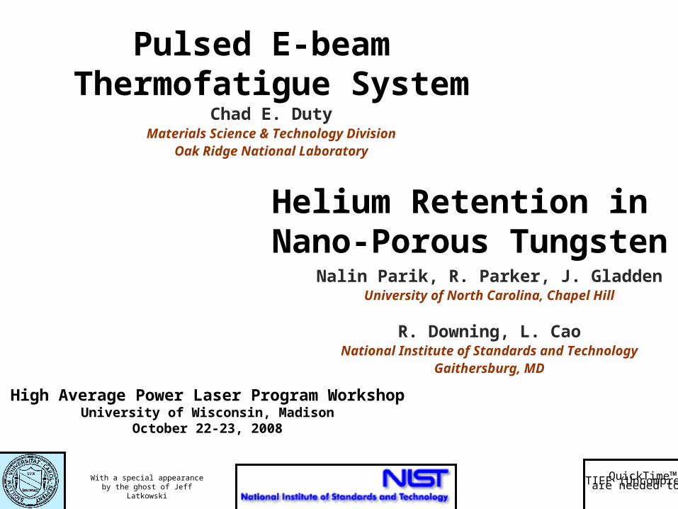
High Average Power Laser Program WorkshopUniversity of Wisconsin, Madison
October 22-23, 2008
Pulsed E-beam Thermofatigue System
Chad E. DutyMaterials Science & Technology Division
Oak Ridge National Laboratory
Helium Retention in Nano-Porous Tungsten
Nalin Parik, R. Parker, J. GladdenUniversity of North Carolina, Chapel Hill
R. Downing, L. CaoNational Institute of Standards and Technology
Gaithersburg, MD
QuickTime™ and aTIFF (Uncompressed) decompressorare needed to see this picture.With a special appearance by the
ghost of Jeff Latkowski
Pulser Unit
High VoltageShield Electron Gun
&Chamber
Vacuum System& Controls
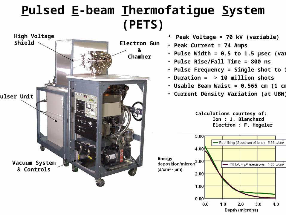
Pulsed E-beam Thermofatigue System (PETS)
Calculations courtesy of: Ion : J. Blanchard Electron : F. Hegeler
• Peak Voltage = 70 kV (variable)
• Peak Current = 74 Amps• Pulse Width = 0.5 to 1.5 µsec (variable)• Pulse Rise/Fall Time = 800 ns• Pulse Frequency = Single shot to 100 Hz• Duration = > 10 million shots• Usable Beam Waist = 0.565 cm (1 cm2 area)• Current Density Variation (at UBW) ≈ 3:1
FY-08 Goals
• Design, fabricate, install heated sample stage.
• Demonstrate high-cycle, high vacuum operation on heated tungsten sample.
• Prepare for use with radioactive samples (FY-10 and beyond.)

Sample Holder / Cooling Design
• Functions
-- Hold sample securely
-- Permit optical access (from both top & sides)
-- Versatile clamping design (allow for various sample dims)
-- Cool sample (provide heat sink for e-beam energy)
-- Heat sample (low temp thermal processing / aging)
-- Electrically ground sample (prevents sample from charging)
-- Measure temperature (either fast TC or melt blocks)
Useable Beam Waist(Ø = 1.13 cm)
Tungsten Target(1-2mm thick)
MolybdenumClamping Disks
(1-2mm thick ea)
Molybdenum Cap(λ = 138 W/mK)
Quick ResponseThermocouple
(Under Development)Ceramic ResistiveHeating Element
(12A, 250W)
Coaxial StainlessSteel Cooling Tube
(λ = 26.3 W/mK)
Thin Fins(Tube Alignment)
Coaxial Water Flow(0.5 gpm)
High ConductivityWire to Ground
(7 Gauge)
Ø = 1.25”

Sample Holder / Cooling Design
1 Ω
Oscilloscope~74V Peak
NeslabMerlin M-33Recirculating
WaterChiller
E-beam chamber suppliedby HeatWave Inc.
Path to groundfor electrons
Ceramic Insulatorfor 8” Conflat
(prevents e- from returningto copper anode )
Thermocouple / Electrical
Feedthrough
Rated 1250Wat 1.5 gpm
Use oscilloscope to measurevoltage drop across a 1 resistor
(1 V ≈ 1 A through e-beam)
Resistive Heater& Thermocouple
Leads
Sample Holder(previous slide)
~8”

Finite Element Thermal Analysis
• Radial Symmetry
• Steady State
• Resistive Heater (250 W)
• Coolant Flow Tinf = 10-20dC hoff = 50 W/mK hon = 5,000 W/mK
• Radiation Tinf = 20dC = 0.2 (free surfaces)
• Conduction W = 174 W/mK Mo = 138 W/mK Steel = 26 W/mK Insul = 1 W/mK
Developed preliminary finite element model of sample holder in ABAQUS.
E-beam Heating OptionsEqual
Inside = 738 W/cm2
Outside = 738 W/cm2
2:1 SplitInside = 428 W/cm2
Outside = 856 W/cm2
Example Case
E-beam = 2:1 SplitHeater = 250 W
Coolant = 5,000 W/mK
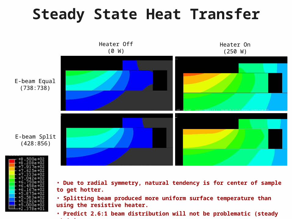
Steady State Heat Transfer
• Due to radial symmetry, natural tendency is for center of sample to get hotter.
• Splitting beam produced more uniform surface temperature than using the resistive heater.
• Predict 2.6:1 beam distribution will not be problematic (steady state).
E-beam Equal(738:738)
E-beam Split(428:856)
Heater Off(0 W)
Heater On(250 W)
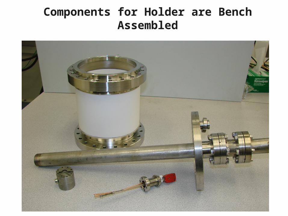
Components for Holder are Bench Assembled

(lack of) Progress since last HAPL Meeting
• Prior to previous HAPL meeting a series of vacuum leaks were plugged and issues with power conditioning resolved.
• Held 10-8 Torr Vacuum for 5 months
• After resolving issues with radiological operation (75 mR/hr operation,) we moved onto long duration test of ebeam.
----> immediately and still frustrated by operational issues.

Interference / Pressure Spike?
• Baseline pressure = 1x10⁻⁷ Torr
• Pulse at 1 Hz, 30 kV
• Pressure pulse to 4x10⁻⁷ Torr
• Pulse in sync with 1 Hz e-beam
• Occasional spike of 7x10⁻⁷ Torr (trip)
• Shield cables & ground system
• Verify system pressure pulse on separate gauge
• Conclusion: Pressure pulse is real
• If so, should “bake out” overnight
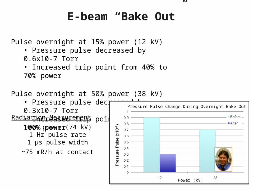
E-beam “Bake Out”
Pulse overnight at 15% power (12 kV)• Pressure pulse decreased by 0.6x10⁻⁷ Torr• Increased trip point from 40% to 70% power
Pulse overnight at 50% power (38 kV)• Pressure pulse decreased by 0.3x10⁻⁷ Torr• Increased trip point from 70% to 100% power
Power (kV)
Pressure Pulse Change During Overnight Bake Out
Radiation Measurement
100% power (74 kV)1 Hz pulse rate1 μs pulse width
~75 mR/h at contact

Chamber Leaks & Water Vapor
“Condition” the chamber by running e-beam
• After 4 days of running, pressure unstable• Beam expanding to hit chamber walls• Excessive heat on end plates / gaskets• Surfaces oxidizing & thermally cycling• Water vapor and leaks due to thermal expansion need to be dealt with.
No sample
Leaks
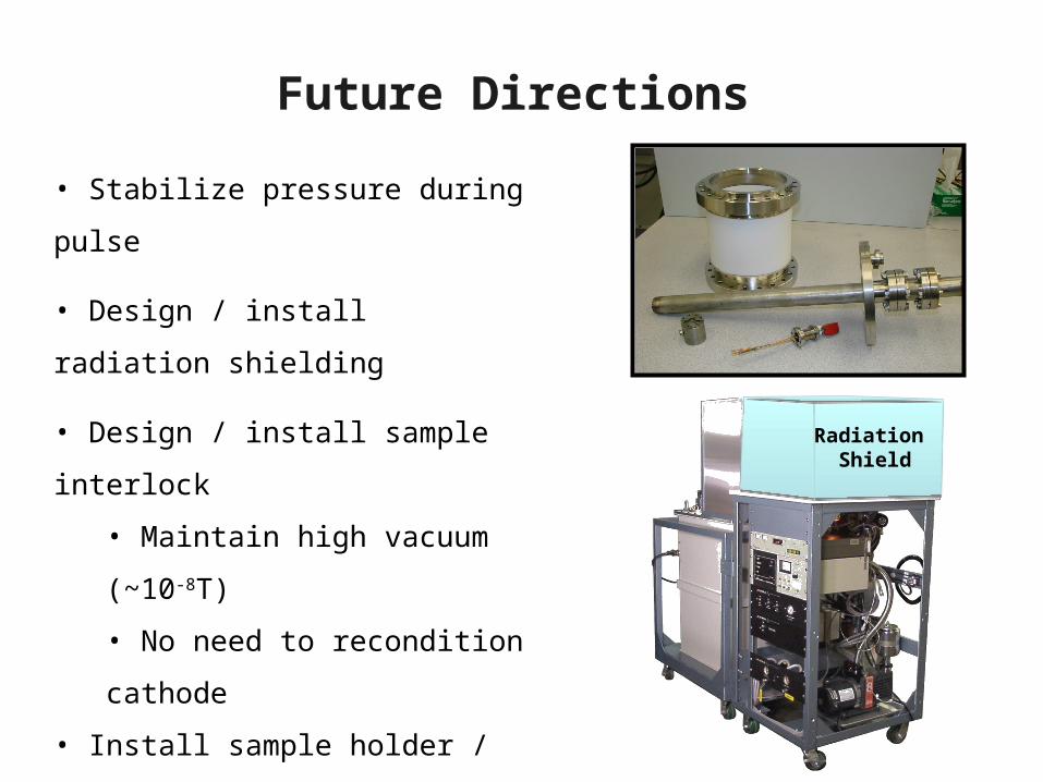
Future Directions
• Stabilize pressure during pulse
• Design / install radiation shielding
• Design / install sample interlock
• Maintain high vacuum (~10-8T)
• No need to recondition cathode
• Install sample holder / target
• Adequately cool sample
• Increase radiation levels
• Start processing samples
Radiation Shield
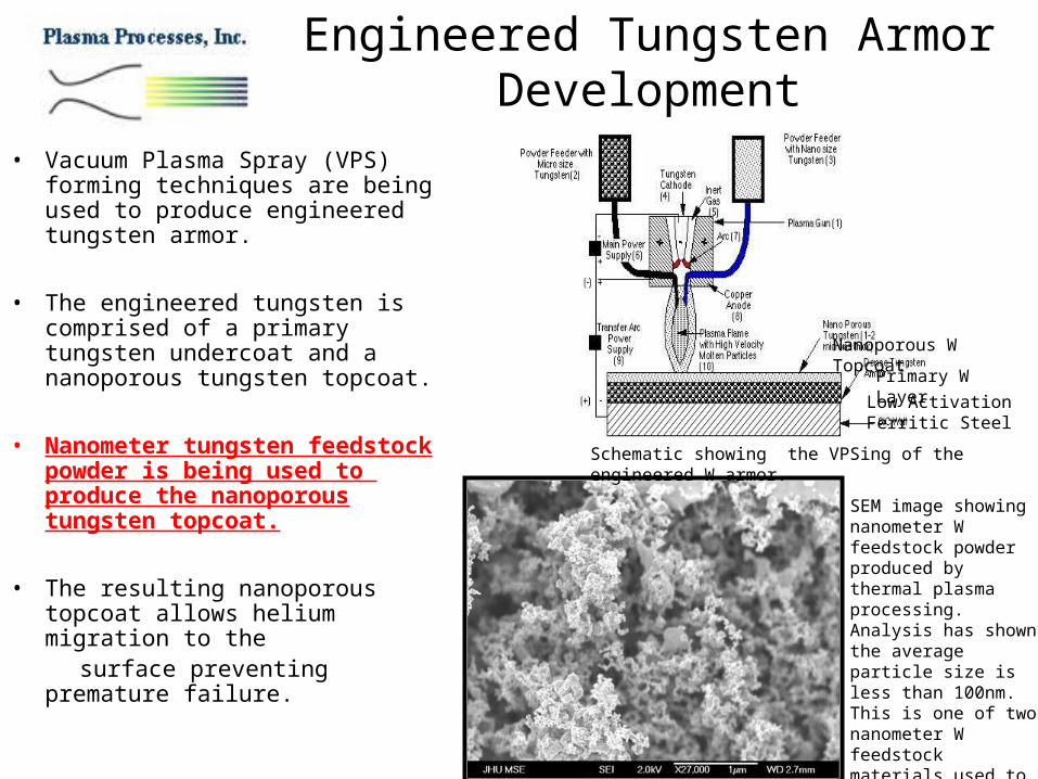
Engineered Tungsten Armor Development
• Vacuum Plasma Spray (VPS) forming techniques are being used to produce engineered tungsten armor.
• The engineered tungsten is comprised of a primary tungsten undercoat and a nanoporous tungsten topcoat.
• Nanometer tungsten feedstock powder is being used to produce the nanoporous tungsten topcoat.
• The resulting nanoporous topcoat allows helium migration to the
surface preventing premature failure.
Low ActivationFerritic Steel
Primary W Layer
Nanoporous W Topcoat
Schematic showing the VPSing of the engineered W armor.
SEM image showing nanometer W feedstock powder produced by thermal plasma processing. Analysis has shown the average particle size is less than 100nm. This is one of two nanometer W feedstock materials used to produce the nanoporous topcoat.

Retention of Monoenergetic Helium
0.00
0.20
0.40
0.60
0.80
1.00
1.20
1E+16 1E+17 1E+18 1E+19
Dose/Cycle (He/m 2)
Relative
3He retention Single Crystal
Polycrystalline
Relative 3He retention for single crystal and polycrystalline tungsten with a total dose of 1019 He/m2. Percentage of retained 3He compared to implanting and annealing in a single cycle.
• Implanted 1019 3He/m2 (1.3 MeV) at 850°C followed by a flash anneal at 2000°C
• Same total dose was implanted in 1, 10, 100, and 1000 cycles of implantation and flash heating
2.5 MV Van de Graaff accelerator2.5 MV Van de Graaff acceleratorImplant Implant 33He Threat Spectrum by Degrading He Threat Spectrum by Degrading Energy of Mono energetic beam at various Energy of Mono energetic beam at various temperature and flash heating at 2000temperature and flash heating at 200000 C. C.
20 MW Nuclear Reactor- Cold neutron source20 MW Nuclear Reactor- Cold neutron sourceMeasure helium retention by neutron depth Measure helium retention by neutron depth profiling (NDP) technique (NIST, Gaithersburg, profiling (NDP) technique (NIST, Gaithersburg, MD)MD)
1 i/a10 i/a
100 i/a
1000 i/a

He retention comparisons for 1e1020 3He/m2
Nano-Cavity W(<100nm Particles)
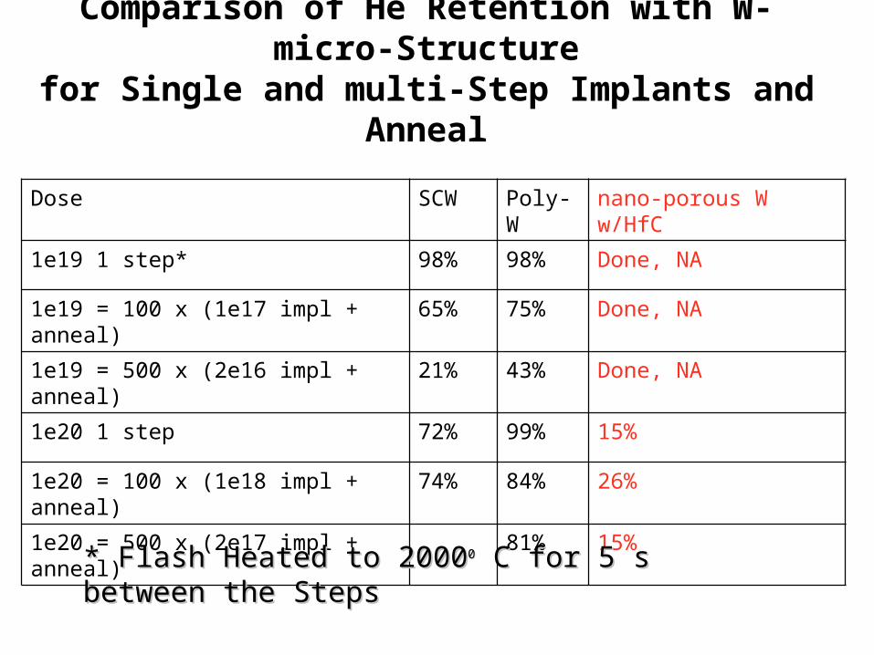
Dose SCW Poly-W nano-porous W w/HfC
1e19 1 step* 98% 98% Done, NA
1e19 = 100 x (1e17 impl + anneal) 65% 75% Done, NA
1e19 = 500 x (2e16 impl + anneal) 21% 43% Done, NA
1e20 1 step 72% 99% 15%
1e20 = 100 x (1e18 impl + anneal) 74% 84% 26%
1e20 = 500 x (2e17 impl + anneal) 81% 15%
Comparison of He Retention with W- micro-Structure
for Single and multi-Step Implants and Anneal
* Flash Heated to 2000* Flash Heated to 200000 C for 5 s between the C for 5 s between the StepsSteps

Results of Surface Blistering/Exfoliation Study
Samples Implanted at 8500 C at High Dose of He and then Heated to 20000 C for 10 s.
Single implant/anneal
Comparison between Comparison between
Poly-W vs. nano-cavity W.Poly-W vs. nano-cavity W.

Exfoliation- Poly-W vs. Nano-Cavity W
Poly-WPoly-W with 2 x 10 with 2 x 102121 He/m He/m22 in 1 step Plo in 1 step Ploly-Wly-W with 1 x 10 with 1 x 102222 He/mHe/m22 in 1 step in 1 step
nano-W nano-W unimplanted unimplanted nano-W nano-W with 5e21 with 5e21 He/mHe/m22 in 1 step in 1 step
(>100 hrs) (>100 hrs)

5e21 He/m2 in Nano-Cavity W

Surface Exfoliation Resultsof Poly-W vs. Nano-porous W
Iwakiri 20005000 nm
• Poly-W with 2 x 10²¹ He/m2 showed blistering• Poly-W with 1 x 10²² He/m2 showed exfoliation
• Nano-cavity W with 5x 10²¹ He/m2 did not show Surface
blistering or exfoliation

Nanoporous W He Retention Remarks• Helium retention in tungsten is a strong function of the amount of helium
implanted prior to annealing. For HAPL-relevant implant/anneal conditions polycrystalline materials exhibit more retention than single crystal. This indicates that microsctructure and perhaps impurities may be important factor in helium retention.
• Nanoporous tungsten appears to have significantly less retention than both polycrystalline and single crystal tungsten. This result is supported by the lack of blistering / exfoliation in the as-implanted surface, supporting reduced “path length” argument for mitigating helium retention. These results should be considered preliminary.
• Further study into the release kinetics, as well as the structure of the implanted surface is required, though results are encouraging for this material system. – --> need for thermal desorption analysis– --> need to reproduce cyclic implantation/anneal study for
nanoporous materials– --> need to move to more relevant annealing condition (degraded
helium deposition and laser annealing with in-situ thermal desorption.)