![Shaping neuroplasticity by using powered exoskeletons in ... · for the patient of a real-world setting ambulation [10, 11]. To this end, wearable powered exoskeletons, e.g., the](https://static.fdocuments.in/doc/165x107/5f0c28a57e708231d434072f/shaping-neuroplasticity-by-using-powered-exoskeletons-in-for-the-patient-of.jpg)
Hierarchically Structured Nanomaterials for ... Structured Nanomaterials for Electrochemical Energy...
28
German Edition: DOI: 10.1002/ange.201506394 Energy Materials International Edition: DOI: 10.1002/anie.201506394 Hierarchically Structured Nanomaterials for Electrochemical Energy Conversion Panagiotis Trogadas,* Vijay Ramani, Peter Strasser, ThomasF. Fuller, and Marc-Olivier Coppens* A ngewandte Chemi e Keywords: electrochemical energy devices · hierarchical materials · hollow nanoparticles · Kirkendall effect · nature-inspired engineering . Angewandte Reviews P. Trogadas, M.-O. Coppens et al. &&&& # 2015 Wiley-VCH Verlag GmbH & Co. KGaA, Weinheim Angew. Chem. Int. Ed. 2015, 54, 2 – 29 Ü Ü These are not the final page numbers!
-
Upload
hoangkhanh -
Category
Documents
-
view
226 -
download
3
Transcript of Hierarchically Structured Nanomaterials for ... Structured Nanomaterials for Electrochemical Energy...
German Edition: DOI: 10.1002/ange.201506394Energy MaterialsInternational Edition: DOI: 10.1002/anie.201506394
Hierarchically Structured Nanomaterials forElectrochemical Energy ConversionPanagiotis Trogadas,* Vijay Ramani, Peter Strasser, Thomas F. Fuller, andMarc-Olivier Coppens*
AngewandteChemie
Keywords:electrochemical energy devices ·hierarchical materials ·hollow nanoparticles ·Kirkendall effect ·nature-inspiredengineering
.AngewandteReviews P. Trogadas, M.-O. Coppens et al.
&&&& � 2015 Wiley-VCH Verlag GmbH & Co. KGaA, Weinheim Angew. Chem. Int. Ed. 2015, 54, 2 – 29� �
These are not the final page numbers!
1. Introduction
“Hierarchy” is derived from the Greek words hieros(sacred) and archein (rule), and it refers to an organizationalstructure in which items are ranked according to levels ofimportance. In the case of hierarchically structured materials,an organizational structure exists consisting of n scales ofa recognized structure. In nature, structural hierarchy isa prevailing feature observed in numerous biological materi-als from macroscopic to microscopic length scales.[2] Theproperties of these biological materials result from a complexinterplay between surface structure, morphology, and physicaland chemical properties.[3] A significant difference betweenstructural control in traditional and biological materials is thegeometrical occurrence of defects. Defects tend to berandomly distributed over the volume of engineered materi-als, whereas biological materials consist of a much moreordered structure that reaches down to the nanoscale.[4] Thedefects are judiciously placed throughout the structure andsignificantly affect the properties of the biological material.[4]
Cytoskeletons, bone, shells, sea sponge exoskeletons andspider silk[4,5] are examples of biological materials withsuperior mechanical properties, such as strength, robustness,toughness and elasticity, due to their precise architecture,comprising structurally inferior building blocks, arrangedalong multiple hierarchical levels.[2b] The cytoskeleton of cellscontrols their shape and structural integrity through aninterplay between intricate protein structures and hierarchi-cally arranged signaling cascades.[4] The nanostructure ofbones consists of mineral crystal platelets embedded ina collagen matrix, resulting in high overall toughness of thematerial, several orders of magnitude higher than that of theconstituting minerals.[6]
The unique characteristics of such biological materials hasdirected research towards the utilization of hierarchicallystructured nanomaterials in applications that require fast andefficient transport through high surface area porous frame-works, such as in separations, energy storage, catalysis andchemical sensing.[7] In the field of catalysis in electrochemical
systems in particular, the active sitesare located in the micro- and meso-pores (nanopores), while the macro-pores promote facile diffusion of spe-cies toward and away from these active
sites.[7, 8] Moreover, the presence of different pore sizes resultsin short electron and ion transport paths as well as largesurface areas leading to enhanced catalytic activity.[7, 8] How-ever, the design of such multi-scaled porous materials withcontrollable ordered pore sizes and structures still remainsa challenge; the majority of synthesis techniques of hierarch-ical materials used nowadays are complex and expensive.[9]
In this Review, we critically discuss the state of the art inresearch on the synthesis of hierarchically mesoporous–macroporous structured materials and their applications invarious electrochemical devices, such as batteries, photo-electrochemical cells and fuel cells. We present for the firsttime a novel approach to improve the design of thesehierarchical materials by taking inspiration from nature.Nowadays, a biomimetic rather than a truly nature-inspiredapproach is often used to synthesize new hierarchicalmaterials with sub-optimal results since this mimeticapproach is focused on imitating isolated features of biolog-ical structures and the actual physical processes that governthe system are neglected. Developing fundamental under-standing of how desired properties of biological systems are
Hierarchical nanomaterials are highly suitable as electrocatalysts andelectrocatalyst supports in electrochemical energy conversion devices.The intrinsic kinetics of an electrocatalyst are associated with thenanostructure of the active phase and the support, while the overallproperties are also affected by the mesostructure. Therefore, bothstructures need to be controlled. A comparative state-of-the-art reviewof catalysts and supports is provided along with detailed synthesismethods. To further improve the design of these hierarchical nano-materials, in-depth research on the effect of materials architecture onreaction and transport kinetics is necessary. Inspiration can be derivedfrom nature, which is full of very effective hierarchical structures.Developing fundamental understanding of how desired properties ofbiological systems are related to their hierarchical architecture canguide the development of novel catalytic nanomaterials and nature-inspired electrochemical devices.
From the Contents
1. Introduction 3
2. Synthesis 4
3. Applications 10
4. From Biomimetics to RationalDesign and Nature-InspiredEngineering 19
5. Conclusions and Outlook 21
[*] Dr. P. Trogadas, Prof. M.-O. CoppensDepartment of Chemical Engineering and EPSRC Centre for NatureInspired Engineering, University College LondonTorrington Place, London, WC1E 7JE (UK)E-mail: [email protected]
Prof. V. RamaniCenter for Electrochemical Science and Engineering, Department ofChemical and Biological Engineering, Illinois Institute of TechnologyChicago, IL 60616 (USA)
Prof. P. StrasserThe Electrochemical Energy, Catalysis, and Materials Science Labo-ratory, Department of Chemistry, Chemical Engineering Division,Technical University Berlin, Berlin, 10623 (Germany)
Prof. T. F. FullerSchool of Chemical & Biomolecular EngineeringGeorgia Institute of Technology, Atlanta, GA, 30332-0100 (USA)
Hierarchical NanomaterialsAngewandte
Chemie
&&&&Angew. Chem. Int. Ed. 2015, 54, 2 – 29 � 2015 Wiley-VCH Verlag GmbH & Co. KGaA, Weinheim www.angewandte.org
These are not the final page numbers! � �

related to their hierarchical architecture iscrucial and can guide the development ofnovel, highly efficient catalytic nanomaterialsand nature-inspired electrochemical devices.
2. Synthesis
A range of experimental methods is used tooptimally combine electrochemical function-alities into hierarchical porous materials.Examples, discussed below, include (sacrifi-cial) templating, galvanic replacement reac-tions, and the Kirkendall effect.
2.1. Templating Methods
Templating is among the most frequentlyused methods to synthesize hierarchical porousmaterials with features ranging from nano-meters to micrometers. Templating can bedifferentiated into soft[10] and hard templat-ing,[11] depending on the physical and chemicalcharacteristics of the template used.[12]
In soft templating, amphiphilic organicsurfactants or block copolymers are typically used as struc-ture-directing agents; these molecules are self-assembled withinorganic precursors or nanoparticles into organized organic–inorganic hybrids.[13] The soft templates are removed, often byheating, producing ordered mesoporous inorganic materials.
During hard templating, inorganic precursors adhere tothe surface of the template or fill the voids of a preformedhard template (mesoporous silica, carbon or colloidal spher-es).[13b] The template is then removed by etching with HF orNaOH, or heat-treatment in air,[11b,14] resulting in theformation of a hollow or negative replica of the template,[13b]
depending on whether the precursor was coated on thesurface or filled the vacancies of the template, respectively.
Reactive hard-templating combines the advantages ofhard-templating with in-situ decomposition of the template toremove the latter.[15] The template is synthesized fromnanostructures of a solid-state reactant that vanishes com-pletely at elevated reaction conditions. This method is veryuseful for high-temperature transformations, such as thesynthesis of macroporous Ti3N4/C composites (Figure 1).[16]
The utilization of graphitic carbon nitrides (g-C3N4) asreactive hard templates enables the direct synthesis ofTi3N4/C, since carbon nitrides can act as nitrogensource,[15, 17] releasing nitrogen in the form of ammoniaduring their thermal decomposition.[15] Macroporous Ti3N4/C composites demonstrate a 5-fold increase in surface area,due to the thinner pore walls and the additional porositycreated by interstitial sites between the hollow Ti3N4/Cspheres.[13a]
Colloidal Crystal Templating. An example of hardtemplating is the colloidal crystal templating, which is usedfor the synthesis of 3D ordered macroporous (3DOM)nanomaterials.[18] This templating method comprises three
simple steps: 1) a colloidal crystal is formed, consisting ofuniformly sized spheres formed through various chemicalprocesses, such as chemical vapor deposition (CVD),[19] sol–gel synthesis,[20] polymerization[21] and electrodeposition;[22]
2) the interstitial spaces of the crystal are filled with a fluidprecursor capable of solidification; and 3) the template is thenremoved to obtain a porous inverse replica (Figure 2).[18]
Despite the simplicity of this technique, optimization ofprecursor/template interactions as well as chemical reactionsis needed to control the 3DOM (sub-)structure and meet
Figure 1. SEM images of the macroporous carbon nitride template with 500 nm pores(CN-500) (top) and the obtained TiN-500 (bottom).[13a] Scale bars: 200 nm. Copyright2008 American Chemical Society.
Figure 2. Schematic of the colloidal crystal templating process. Thetemplate with the structure of an opal is infiltrated with precursormaterial. Processing and template removal produce the inverted(3DOM) structure.[23] Copyright 2013 American Chemical Society.
.AngewandteReviews
P. Trogadas, M.-O. Coppens et al.
&&&& www.angewandte.org � 2015 Wiley-VCH Verlag GmbH & Co. KGaA, Weinheim Angew. Chem. Int. Ed. 2015, 54, 2 – 29� �
These are not the final page numbers!

specific goals for materials design such as pore topology andmicro/mesopore shape.[13b,18]
The diameter of the ordered macropores can be altered byvarying the diameter of the spheres in the colloidal crystaltemplate,[13b] while the diameter of the windows that connecteach macropore to its neighbor can be tuned by controllingthe synthesis conditions.[24] The main parameters controllingthe entrance size of the macropores are the acid concentrationand the sintering conditions of the colloidal crystal tem-plates.[24] As the acid concentration increases, the mesoporesize slightly decreases (4.7 to 3.6 nm) and the macroporeentrance size gradually increases from 0 to 200 nm(Figure 3).[24] A similar effect is observed upon increasingthe sintering temperature of the polymeric colloidal crystaltemplate (90 8C), as it leads to a wide macropore entrance of150 nm.[24] The resultant material is characterized by 3Dordered macropores (1 mm) with tunable entrance size, 2Dhexagonally packed mesopores (4 nm), high surface area(330 m2 g�1) and large pore volume (0.36 cm3 g�1).[24] Thesetunable materials with adjustable entrance size can be used invarious applications, such as drug delivery and nanofiltration.
The alignment of the mesopores can be tuned throughchanges in solvent polarity. During the synthesis of 3D silicatematerials, a polystyrene template is spin-coated with a pre-cursor solution containing pluronic triblock copolymer P123and tetramethyl orthosilicate (TMOS) in methanol and/orwater; the resulting SiO2 mesostructure consists of hexago-nally arranged pores parallel to the substrate (Figure 4 a).[25]
Upon increase of the water content of the precursor solution,hexagonally arranged spherical pores are obtained (Fig-ure 4b,c) due to an increase in affinity of the polyethyleneoxide (PEO) block for the wall.[25] However, precise con-trol over microporosity is difficult toachieve.[13b]
2.2. Chemical Vapor Deposition (CVD)
Well-ordered mesoporous carbonmaterials used as catalysts supports,electrode materials and templates areusually synthesized by sacrificial tem-plating methods;[26] mesoporous silica/zeolite is infiltrated with carbon pre-cursors and subjected to carbonizationat high temperature and selectiveremoval of the inorganic tem-plates.[26, 27] Chemical vapor deposition(CVD) can be successfully used tocontrol morphology, pore size andgraphitization in well-ordered mesopo-rous carbons, leading to enhanced ther-mal stability and electrical conductivityof the material.[26,28] In general, CVDinvolves chemical reactions betweengaseous reactants in an activating envi-ronment, followed by the formation ofstable solid product.[29] It is a combina-tion of heterogeneous and homogene-
ous chemical reactions occurring in the gas phase neara heated surface, leading to the formation of powders,coatings or films.[29, 30]
As an example of CVD nanocasting, mesoporous silicaSBA-15 rods (100–400 nm diameter and 1–2 mm length) havebeen used as hard templates to nanocast graphitic mesostruc-tured carbon nanotubes and nanorods with tunable poresize.[28c] The pore size of the carbon is tunable between 2 and4.5 nm depending on the structure of the SBA-15 template.[28c]
The pore size of silica directs the morphology of themesoporous carbon. CVD nanocasting of SBA-15 silica rods
Figure 3. SEM images of the hierarchically ordered meso/macroporoussilica samples using a) 0.1, b) 0.3, c) 0.5, and d) 0.8 g of 2m HClsolution.[24] Scale bars: 1 mm. Copyright 2011 American ChemicalSociety.
Figure 4. SEM images of textural mesoporosity of 3DOM SiO2: a–d) parallel mesopores formedwith methanol as the solvent; e–h) transitional mesophases with methanol/water co-solvents;and i–l) possibly vertical mesophase and spherical mesopores formed in water.[25] Copyright 2012American Chemical Society.
Hierarchical NanomaterialsAngewandte
Chemie
&&&&Angew. Chem. Int. Ed. 2015, 54, 2 – 29 � 2015 Wiley-VCH Verlag GmbH & Co. KGaA, Weinheim www.angewandte.org
These are not the final page numbers! � �

synthesized at low aging temperature (40 and 70 8C) leads tothe formation of hollow mesoporous carbon rods, whereasSBA-15 rods synthesized at high crystallization temperature(100 and 130 8C) result in solid-core mesoporous carbon rods(Figure 5).[28c]
During the CVD process, the carbon precursor is initiallyin contact with the surface of SBA-15 silica rods beforediffusing into the interior of the rods. In the case of SBA-15silica templates with small pore diameter, the deposition ofcarbon on the surface of the silica rods can quickly block thepore channels and impede the diffusion of carbon precursorinto the core of the silica rods forming a carbon/silicacomposite with a carbon-rich, wormhole-type outer shelland an inner core of pure silica (Figure 5a,b).[28c] On thecontrary, SBA-15 silica templates with large pore diameterallow the penetration of acetonitrile into the core of the silicarods, forming uniform carbon/silica composites and, hence,solid-core carbon rods (Figure 5c,d).[28c]
2.3. Kirkendall Effect
Hollow nanoparticles with controlled interior void andshell thickness are an important class of nanoporous materi-als. The most popular method to synthesize hollow nano-structures is the template-mediated approach.[31] By coatingthe surface of the template particles with desired materialsand removing the template via post-treatment, various hollowparticles can be easily obtained.[31a] However, the maindisadvantage of this method is the size limitation, as thehollow particles obtained are larger than 200 nm; further-more, the post-treatment necessary to remove the templatesadds complexity to the whole synthesis procedure andincreases the chance of structural deformation and introduc-tion of impurities.[31a] To overcome these limitations, novelsynthetic strategies are used based on the Kirkendall effect[32]
and the galvanic replacement reaction discussed in the nextsection.[33]
The Kirkendall effect is a common phenomenon inmetallurgy,[34] used to describe the formation of voids at theinterface of two metals due to their different inter-diffusionrates.[34a, 35] In a nanoparticle system, the Kirkendall effectrefers to preferred outward elemental diffusion, leading toa net material flux across the spherical interface and theconsequent formation of a single void at the center.[31a, 32a,36]
For example, the formation of intermediate core–shell–voidFe–Fe3O4 nanoparticles is observed during the synthesis ofhollow Fe3O4 nanoparticles.[35] These hollow nanoparticles areprepared by controlled oxidation of amorphous core–shellFe–Fe3O4 obtained by high-temperature, solution-phasedecomposition of Fe(CO)5 and air oxidation of the amor-phous Fe nanoparticles at room temperature.[35] A dispersionof Fe–Fe3O4 nanoparticles in hexane is then added toa mixture of 1-octadecene and trimethylamine N-oxide(Me3NO) and, after calcination at high temperature, hollowFe3O4 nanoparticles are produced.[35]
An increase in reaction temperature and reaction timeresults in the formation of a series of intermediate voidstructures, which serves as evidence of the Kirkendalleffect.[35] The rate of core consumption and gap broadeningbetween Fe and Fe3O4 is significantly enhanced at higherreaction temperatures. The core diameter shrunk to 5 nm andthe gap between Fe and Fe3O4 increased to 2.5 nm afterheating at 210 8C for 40 min, whereas the core was almostdepleted after heating at 210 8C for 80 min.[35] The majority ofcores disappeared after heating for 2 h at 210 8C, resulting inthe formation of spherical voids in the center of the nano-particles (Figure 6).
The Kirkendall effect can also be employed for thefabrication of 1-D hollow nanomaterials such as ZnAl2O4 viasolid–solid reaction of ZnO–Al2O3 core–shell nanowires.[34a,37]
Small voids are generated initially by bulk diffusion at the
Figure 5. SEM images of graphitic mesoporous carbon materials usingvarious mesoporous silica SBA-15 rods as templates at different agingtemperatures: a) 40 8C, b) 70 8C, c) 100 8C, and d) 130 8C.[28c] Scalebars: 500 nm. Copyright 2005 American Chemical Society.
Figure 6. a–f) TEM images showing the shape evolution of Fe–Fe3O4
core–shell nanoparticles a) via the Kirkendall effect. Core–shell–voidintermediates obtained by the reaction for 1 h (b) and 2 h at 130 8C(c), and 40 min (d) and 80 min at 2108C (e). f) Hollow Fe3O4 nano-particles from the reaction for 120 min at 210 8C.[35] Copyright 2007Wiley.
.AngewandteReviews
P. Trogadas, M.-O. Coppens et al.
&&&& www.angewandte.org � 2015 Wiley-VCH Verlag GmbH & Co. KGaA, Weinheim Angew. Chem. Int. Ed. 2015, 54, 2 – 29� �
These are not the final page numbers!

interface; as diffusion progresses, the number of voids incontact with the inner surface of the shell increases and, thus,the surface diffusion of atoms of the core material becomesdominant along the skeletal bridges. This observation sug-gests that surface diffusion processes might be the dominantmass flow mechanism for the growth of the interior poresafter their initial nucleation and formation due to theKirkendall effect.[34a, 38]
2.4. Galvanic Replacement Reaction
The galvanic replacement reaction provides a simple andversatile route for the synthesis of hollow metal nanoparti-cles.[33b, 39] The electrochemical potential difference betweentwo metals drives the reaction, with one metal serving as thecathode and the other one as the anode.[39b, 40] A commonexample is the zinc (Zn)/copper (Cu) couple; the Zn2+/Znreduction potential (�0.76 V vs. SHE) is more negative thanthe Cu2+/Cu potential (0.34 V vs. SHE), resulting in theoxidation of Zn to Zn2+ and the reduction of Cu2+ to Cu.[39b,41]
Hollow metal Au, Pt and Pd nanocubes are synthesized bygalvanic replacement using Ag as the sacrificial template forthe formation of metal nanostructures.[33b, 39a,b,d–g] The standardreduction potential of AgCl/Ag is 0.22 V (vs. SHE), which islow compared to the standard potential of AuCl4
�/Au (0.99 Vvs. SHE), PdCl4
2�/Pd (0.59 V vs. SHE) and PtCl42�/Pt (0.76 V
vs. SHE). Hence, when silver nanoparticles co-exist withAuCl4
� ions in the solution, Ag nanocubes are oxidized byHAuCl4 according to the following reaction:
3 AgþHAuCl4 ! Auþ 3 AgClþHCl ð1Þ
The produced Au is confined to the nanocube surface,growing on the cube and adopting its morphology, as interiorAg is oxidized to produce a hollow structure.[33b] Themorphological changes at the Ag surface at various stagesof the galvanic replacement reaction can be observed byscanning electron microscopy (SEM) and transmission elec-tron microscopy (TEM). Once Ag nanocubes react withHAuCl4, a pinhole is created on one of the six facets of eachcube (Figure 7) revealing that the reaction is initiated ata high energy site.[33b] As the galvanic replacement reactionproceeds, the pinhole serves as the anode where Ag isoxidized;[33b] the released electrons migrate to the facets of thecube and are captured by AuCl4
� , generating Au atoms thatepitaxially grow on the nanocube.[33b]
The same experimental procedure can be used to producePt and Pd nanoboxes where Na2PtCl4 and Na2PdCl4 are usedas the starting solutions. However, the observed morpholog-ical changes are different from those with the Au/Ag couple.In the case of Pt nanocubes, the structure consists of roughwalls, due to the lack of solid-solid inter-diffusion between Ptand Ag (Figure S1 in the Supporting Information, SI).[33b] Onthe contrary, solid–solid inter-diffusion does take place in thePd/Ag system, even though pore formation on the structure isblocked by creating a Pd/Ag alloy.[33b]
2.5. Selective Leaching
Hierarchical metal oxides can be synthesized by selectiveleaching of the sacrificial phase of the precursor used.[42] Forthe synthesis of Ni1�xZnxO metal oxides,[42e] a composite withtwo immiscible phases (NiO and ZnO) is obtained from NiII
and ZnII nitrates in solution with urea by evaporation andcombustion (Figure 8a,b). Combustion followed by sinteringleads to a monolith consisting of NiO and ZnO particles(Figure 8c). The ZnO particles are leached in alkali to formmacroporous NiO (Figure 8 d), which is reduced in H2/Ar toyield macroporous Ni metal (Figure 8 e). During NiO reduc-tion, ZnO is removed from the Ni matrix, resulting inadditional porosity of the Ni1�xZnxO (Figure 8e).[42b,e, 43]
Hierarchically porous MnO is synthesized by reduction ofsintered Mn3O4 pellets, with the concurrent loss of volumebeing accommodated through the formation of mesopores.[44]
Mesopore formation is regenerative, as mesoporosity is lostand regained through oxidation and reduction of Mn3O4.Oxidation of the final MnO material results in closing themesopores without the macropore morphology being altered,whereas reduction of Mn3O4 to MnO retains the mesoporenetwork and pore connectivity (Figure 9 b,c).[44c]
Figure 7. A) SEM of Ag nanocubes. B) SEM of product after additionof 0.30 mL of 1 mm HAuCl4 solution to a 5 mL 0.8 mm Ag nanocubesuspension; a pinhole (lower inset) is observed on the exposed face ofapproximately 1 in 6 nanocubes and TEM (upper inset) of a micro-tomed sample reveals early hollowing out. C) SEM of product afteraddition of 0.50 mL of HAuCl4 solution. TEM (inset) of a microtomedsample reveals the hollow interior of the nanobox. D) SEM of productafter addition of 2.25 mL of HAuCl4 solution. Porous nanocages areproduced. e) illustration summarizing morphological changes.[33b]
Copyright 2008 American Chemical Society.
Hierarchical NanomaterialsAngewandte
Chemie
&&&&Angew. Chem. Int. Ed. 2015, 54, 2 – 29 � 2015 Wiley-VCH Verlag GmbH & Co. KGaA, Weinheim www.angewandte.org
These are not the final page numbers! � �

2.6. Aerogels and Porogens
Recently, research has focused on the synthesis andutilization of support-less hybrid aerogels of metal nano-particles (such as Pd, Pt, Au and Ag) as catalysts for ethanol
and oxygen reduction reactions.[45] These novel materialscombine the highly porous structure of aerogels with thecatalytic properties of metal nanoparticles and are formed bytwo different routes.[45a–c]
In the first route (Figure 10, strategy I), metallic nano-particles are formed by reduction of the metal precursor (suchas HAuCl4, AgNO3, H2PtCl6, or PdCl2) followed by gelationof the preformed metal nanoparticles, while in the secondroute (Figure 10, strategy II), the hydrogels are spontane-ously formed from the in-situ reduction of noble metalprecursors with sodium borohydride (NaBH4) in a single step(without the preformation of metallic nanoparticles).[45a] Thefinal step involves the supercritical drying of the hydrogel toobtain the hybrid metallic aerogel. However, this sol–gelprocedure for the synthesis of composite metallic aerogels isdifficult, expensive and toxic.
Alternatively, the use of gas bubbles (generated in a liquidphase chemical reaction) as a porogen for the synthesis ofhollow nanoparticles offers a novel, simple and effectiveapproach avoiding the introduction of impurities, such assurfactants.[1, 46] The gas bubbles create numerous gas–liquidinterfaces inside the continuous solution phase and act as thenucleation and agglomeration centers for the nanocrystals.[46l]
The nucleation and agglomeration process is thermodynami-cally favorable; the forces on the solvent molecules at the gasbubbles/bulk liquid interface are asymmetric and in need ofnanocrystals to stabilize, while the nanocrystals are charac-terized by high surface tension that has to be released in orderto reach a stable state. As a result, the nanocrystals move intothe gas bubbles/bulk liquid interface and once their concen-tration is sufficiently high, the nanocrystals interact with eachother to form hollow microspheres using the gas bubbles asporogens.[46l]
ZnSe hollow microspheres were synthesized based on thismethod.[1] After the initial nucleation, ZnSe monomers growinto nanocrystals (Figure 11 a) that aggregate on the surfaceof N2 micro-bubbles produced during the reaction betweensalts of ZnO2
2� and SeO32� ions and hydrazine (N2H4)
(Figure 11 b), resulting in the formation of hollow ZnSemicrospheres (Figure 11c).[1]
Figure 8. Generation of macroporous materials starting with thecombustion synthetic preparation of an intimate mixture of two metaloxides. Starting from NiII and ZnII nitrates in solution with urea as thefuel “a”, combustion synthesis yields an intimate mixture of the oxides“b”, which is sintered to form the monolith “c”. The ZnO in monolithis leached by alkali to yield a macroporous oxide “d”. Reduction of “d”should yield macroporous Ni metal “e”, but closer examination revealsthat, in addition, ZnO is removed from “d” on reduction, giving rise toanother level of porosity.[42e] Copyright 2002 American ChemicalSociety.
Figure 9. a) SEM images of a Mn3O4 pellet formed under conditionsthat produce porosity. b) Reduction of the Mn3O4 monolith to MnOretains the macroporosity and induces large mesopores in the macro-pore walls, seen clearly at higher magnification in (c). d) On closeinspection, the mesopores are found to be 50 nm on edge and squarein shape.[44c] Copyright 2006 American Chemical Society.
Figure 10. Synthesis of hybrid metallic aerogels via gelation of pre-formed nanoparticles (strategy I) or spontaneous gelation (strate-gy II).[45a] Copyright 2015 Wiley.
.AngewandteReviews
P. Trogadas, M.-O. Coppens et al.
&&&& www.angewandte.org � 2015 Wiley-VCH Verlag GmbH & Co. KGaA, Weinheim Angew. Chem. Int. Ed. 2015, 54, 2 – 29� �
These are not the final page numbers!

2.7. Synthesis Methods: Summary and Outlook
To summarize this section, one of the key goals of researchon nanoporous materials over the past two decades has beenthe development of methods to precisely control the structureat different length scales (macro-, meso- and nanoscale).[47]
The most common route to achieve this goal is the use oftemplates that determine the shape and size of the finalhierarchical structure. Hard templating is the dominantsynthesis technique used thus far, despite its complexity andhigh cost; we firmly believe that the development of new andversatile synthesis methods based on porogens and aerogels(such as gas bubbles, composite aerogels with metal oxides,etc.) will provide a facile, environmentally friendly and morecost-effective route to easily tunable hierarchical structuresand lead to research breakthroughs. Table 1 summarizes theadvantages and disadvantages of the various techniquesutilized today for the synthesis of hierarchical nanostructures,inspired by the comparison table by Chal et al. ,[48] which wasused to assess different synthesis strategies towards zeoliteswith mesopores. The differently grouped synthesis methodshave been judged concerning their manufacturing costs,Health–Safety–Environmental (HSE) issues, synthesis proce-dure, production yield, the predetermined mesoporosity andthe foreseen chance on a future breakthrough development.
Hard templates such as polystyrene spheres, colloidalsilica and metal oxides are extensively used to get hierarchicalstructures with well-defined shapes.[49] The control over the
structure at the various length scales as well as the ease ofsynthesis and commercial availability of the templates makethis method ideal for the synthesis of hierarchical structures;however, the major drawback is the post-processing toremove the template that adds complexity to the wholesynthetic process and increases the chance of structuraldeformation and introduction of impurities.[50] Chemicaletching or calcination at high temperatures are frequentlyused for this purpose, leading to particle size growth of theoxide formed that destroys the pore solid architecture and theinterconnected porosity of the material.[47, 51]
To mitigate these problems, simpler synthetic approacheshave been adopted. Templating against soft (liquid orgaseous) templates such as surfactant micelles, emulsiondroplets or gas bubbles has attracted the greatest attentionand significant progress has been made during the pastdecades.[46f, 49,52] The liquid character of the emulsion dropletsallows the fast and efficient removal of these liquid templatesby evaporation or dissolution in common solvents, likeethanol.[53] Moreover, the high deformability of the emulsiondroplets allows them to accommodate a larger level ofshrinkage reducing the risk of structure deformation (crack-ing) during drying or calcination post-treatment.[46f] Despitethe attractive advantages of soft templating, the control of theshape, size and uniformity of the synthesized hierarchicalmaterial is difficult in comparison to hard templating, as it issensitive to many parameters such as pH, reaction conditions,solvent and ionic strength.[46f, 49]
Apart from the use of polymeric and inorganic non-metaltemplates for the synthesis of hierarchical materials, metaltemplates can also be used. The metal templates have a dualrole: they act as the reactant during the synthesis procedureand as the initial template, which dictates the architecture inthe nanostructure, the void space and the wall thickness of theformed hollow nanoparticles. Generally, two formationmechanisms, the Kirkendall effect and galvanic replacement,have been used to understand the fundamentals of hollowspheres synthesized by metallic templates.[35,36f, 54]
The galvanic replacement reaction provides a facile, high-quality and reproducible process for synthesizing hollownanoparticles without post-treatment.[54a] Galvanic replace-ment occurs spontaneously when the atoms of one metal react
Figure 11. Formation mechanism of ZnSe microspheres via gas bub-bles.[1] Copyright 2003 Wiley.
Table 1: Summary of the various advantages and disadvantages of the synthesis techniques of hierarchical nanoparticles.
Formationroute
Productioncost
HSE[a] issues Synthesisprocedure
Yield Predestinedmesoporousarchitecture
Breakthroughdevelopmentexpected
Destructive Galvanicreplacementreaction
Low No (non-toxic) Simple High Yes No
Kirkendalleffect
Low No (non-toxic) Simple High Yes No
Constructive Aerogels &porogens
Medium (aerogels)Low (gas bubbles)
Yes (aerogels)No (gas bubbles)
Simple High No Yes
Hard templating High Yes Difficult Low Yes No
[a] Health–safety–environment.
Hierarchical NanomaterialsAngewandte
Chemie
&&&&Angew. Chem. Int. Ed. 2015, 54, 2 – 29 � 2015 Wiley-VCH Verlag GmbH & Co. KGaA, Weinheim www.angewandte.org
These are not the final page numbers! � �

with ions of another metal having a higher electrochemicalpotential in a solution phase. The atoms of the first metal areoxidized and dissolved into the solution, while the ions of thesecond metal are reduced and plated on the surface of the firstmetal.[55] Reactions take place in water at medium temper-atures and a very limited amount of reagents is used otherthan the initial template.[55] Despite the simplicity of thismethod, galvanic replacement is used to synthesize a widevariety of nanostructures of controlled composition andporosity, such as hollow/alloyed nanoparticles with tunableoptical properties.[32a, 33b, 54a,e,k,55] However, as the galvanicreplacement reaction itself involves dissolution of the tem-plate structures accompanied by simultaneous deposition onthe surface of templates, it is difficult to precisely control theridge thickness of the final nanostructure.[54e,56] Furthermore,this method is susceptible to surfactant impurities, resulting inselective reaction on specific facets and segregation of alloycomponents.[55]
The Kirkendall effect can also be successfully used for thesynthesis of hollow and tubular nanostructures.[32a, 54e] It isa vacancy mediated mechanism based on the mutual diffusionprocess through the interface of two metals of differentdiffusivities where vacancy diffusion occurs to compensate forthe inequality of the material flow.[32a,36n, 49, 54e] It is a simple,cost-efficient and rapid one-pot synthesis method with nearly100 % selectivity.[32a] There is a need, though, to betterunderstand the mechanism of the Kirkendall effect duringanion exchange or partial anion/partial cation exchange;anions diffuse more slowly than cations due to their larger sizeand, hence, longer reaction times and calcination temper-atures are required.[54a] The slow reaction kinetics can beadvantageous for obtaining control over reaction intermedi-ates that will result in improved morphological control and,thus, lead to heterostructured or hybrid nanoparticles withtunable structure and properties.[54a, 57]
Based on the preceding discussion, it is clear that thetemplating methods are very effective and versatile in termsof synthesizing hierarchical structures, but their high cost andtedious synthetic procedure have prohibited their usage inlarge scale applications. Ideally, a single-step template-freemethod for the synthesis of hierarchical structures of differentsizes would be preferred. Ostwald ripening has recently beenproposed as an effective template-free method for thesynthesis of such structures. It combines the advantages ofhard and soft templating while avoiding their pitfalls;[54k]
uniform meso- and nanostructures of controlled size havebeen prepared.[49,54k, 58] However, further research is needed toprovide fundamental information about the formation mech-anism of these hierarchical materials.
3. Applications
3.1. Lithium Ion Batteries
Hierarchical 3DOM carbon materials are mainly used asactive electrodes in lithium batteries due to their high surfacearea, high effective ionic conductivity of the electrolyte withinthe 3DOM matrix and their interconnected wall structure that
provides a continuous pathway for Li-ions to reach the poroussurface, resulting in good electrical conductivity.[9a, 26a, 59]
3DOM carbon materials are prepared by the colloidalcrystal templating introduced in Section 2.1.[26a] Polymethylmethacrylate (PMMA) colloidal crystals (433 nm) are used asthe starting template; after infiltration with silicate/poly(oxy-ethylene) surfactant solution, followed by calcination toremove PMMA, 3DOM/m SiO2 monoliths are obtainedwith macropores of 300 nm diameter and pore windows of100 nm (Figure 12 A–D).[26a] 3DOM/m SiO2 is used as the
hard template to prepare its carbon replica 3DOM/m C bygas-phase polymerization, carbonization and hydrofluoricacid etching to remove the silica. Nitrogen-doped graphiteis then incorporated into 3DOM/m C by CVD usingacetonitrile as a precursor leading to the final product,namely 3DOM/m amorphous carbon/graphitic carbon nano-composite (3DOM/mC/C).[26a] The deposition time affects thegrowth of the macropore walls, the diameter of which is 58 nmafter 2 h CVD and increases to 90 nm after 5 h deposition(Figure 12 E,F).[26a] The addition of the graphitic phase
Figure 12. SEM images at different processing stages of 3DOMcarbon: A) PMMA colloidal crystal template (scale bar: 1 mm);B) 3DOM/m SiO2 monolith synthesized with PMMA as template(scale bar: 100 nm); C) 3DOM/m Al-SiO2 monolith, obtained fromaluminum impregnation of the 3DOM/m SiO2 monolith (scale bar:100 nm); D) 3DOM/mC, after introduction of polymer, carbonization,and removal of silica with HF (scale bar: 100 nm); E) Carbon/carbonnanocomposites-2 h; and F) Carbon/carbon nanocomposites-5 hcarbon/graphite composite monoliths after CVD reaction times of 2and 5 h, respectively (scale bar: 100 nm).[26a] Copyright 2006 AmericanChemical Society.
.AngewandteReviews
P. Trogadas, M.-O. Coppens et al.
&&&& www.angewandte.org � 2015 Wiley-VCH Verlag GmbH & Co. KGaA, Weinheim Angew. Chem. Int. Ed. 2015, 54, 2 – 29� �
These are not the final page numbers!

increases the electronic conductivity of porous carbon and thelithium capacity at high charge and discharge rates (Figure S2,SI), indicating that hierarchical porosity can be used to tunethe properties of the material.[26a]
PMMA templates are frequently used to synthesizeporous lithium iron phosphate (LiFePO4). Even thoughnon-porous LiFePO4 is commonly used as a cathode materialin lithium ion batteries due to its high capacity (170 mAhg�1),low cost and toxicity,[60] the low intrinsic conductivity ofLiFePO4
[60a,c,61] limits its application at high power.[60–62] Tocircumvent this issue, porous LiFePO4 (Figure 13) is used to
increase the available interfacial area and decrease thelithium-ion diffusion distance, which increases the chargetransport and power capability.[60a,b,63] For example, LiFePO4
prepared with 270 nm PMMA templates offers high surfacearea and improved access to the active LiFePO4, resulting ina discharge capacity of 160 mAhg�1.[60b] Stable dischargecapacity of the meso/macroporous LiFePO4 is observed over50 cycles, reaching 115 mAh g�1 and 93 mAh g�1 at 75 min and150 min discharge, respectively, indicating the high stability ofthis material under cycling at high discharge rates (Figure S3,SI).[60b]
However, the porous LiFePO4 materials synthesized byPMMA templates are not spherical, which reduces theirpacking density and power capability.[63] A 3D nanoporoussphere is the optimal structure for LiFePO4 in order to obtainhigh power output without compromising density. Spraypyrolysis can be used for the synthesis of such 3D nanoporous,spherical nanomaterials with well interconnected pores,providing full access of the electrolyte into the inner part ofthe LiFePO4 sphere (Figure 14).[63] The LiFePO4/C spheresconsist of interconnected hierarchically organized pores,creating 3D electronic and ionic pathways that enhancelithium ion diffusion and electron migration in the liquid andsolid phases, respectively.[63]
At low rates (20 mAg�1), the capacity of 3D LiFePO4/C is165 mAhg�1—close to the theoretical value of 170 mAh g�1—with 100 % retention over 100 cycles (Figure S4 a, SI). At high
rates (1700 mAg�1), the capacity retention over 100 cycles is98% and the average Coulombic efficiency is 99 %, indicatingthe suitability of the material for high power applications.[63]
Furthermore, LiFePO4/C demonstrates superior rate capa-bility, reaching specific capacities of 123 mAhg�1 and106 mAhg�1 at 10C and 20C respectively (Figure S4 b, SI).[63]
Another widely used metal oxide is lithium manganeseoxide (LiMn2O4), due to its high theoretical capacity(150 mAhg�1), which is similar to the capacity of thecommercially used LiCoO2.
[64] 3DOM LiMn2O4 is synthesizedby the colloidal templating method;[65] the ordered hollow
spheres consist of a {1,1,1} and{1,0,0} lattice with 355 nm mac-ropores and 8–12 nm wall thick-ness with a surface area of24 m2 g�1 (Figure S5, SI).Capacity stabilizes at 90 % ofthe initial value, indicating thegood cyclic stability of the mate-rial, while the original capacityof the material is fully regainedat low rates.[65]
Apart from the above men-tioned hierarchical porousmaterials, several other or-dered macro/mesoporous metaloxides are used in lithiumbatteries, including SnO2,
[66]
V2O5,[67] Co3O4,
[68] NiO,[69]
TiO2,[70] LiCoO2
[71] andLiNiO2.
[72]
To sum up, the utilization of hierarchically orderednanoporous metal oxides as cathode materials in lithiumbatteries enhances the rate performance of batteries, since the
Figure 13. SEM images of the colloidal crystal templates (top) and associated LiFePO4 templated samplescalcined at 500 8C (bottom) formed using PMMA beads of diameter 100 nm (a,d), 140 nm (b,e), and270 nm (c,f), respectively.[60b] Copyright 2009 American Chemical Society.
Figure 14. SEM images of a) 3D nanoporous LiFePO4/C spheres;b) the surface of a single sphere; and c,d) cross-sections of spheres,showing the interconnected pores.[63] Scale bars: a) 50 mm,b–d) 10 mm. Copyright 20011 Royal Society of Chemistry.
Hierarchical NanomaterialsAngewandte
Chemie
&&&&Angew. Chem. Int. Ed. 2015, 54, 2 – 29 � 2015 Wiley-VCH Verlag GmbH & Co. KGaA, Weinheim www.angewandte.org
These are not the final page numbers! � �

well interconnected wall structures provide continuous elec-trical pathways, increasing the conductivity of these materials.
3.2. Photocatalysis
Another application of hierarchical materials is in photo-catalysis, which involves the absorption of photons bya molecule or substrate to produce highly reactive electroni-cally excited states.[73] Photo-induced molecular reactionsoccur at the surface of the catalyst[73b] and can be divided intocatalyzed or sensitized photoreactions, depending on thelocation where the initial excitation occurs.[73] In a catalyzedphotoreaction, the initial photo-excitation takes place in anadsorbate molecule that interacts with the ground statecatalyst substrate; whereas, in a sensitized photoreaction, theinitial photo-excitation occurs in the catalyst substrate, which,in turn, transfers electrons into a ground state molecule.[73]
The initial excitation is followed by subsequent electrontransfer from the valence to the conduction band if the energyof the photons exceeds the band width of the semiconduc-tor.[73, 74] When an electron is promoted to the conductionband, this creates an unoccupied state in the valence band(h+).[74a,e] The excited electrons that migrate to the surfaceare used to start the photocatalytic cycle [Eq. (2)](Figure 15),[73, 74] while the rest recombine with unoccupiedstates producing heat.
AþDlight�Eg����!A� þDþ ð2Þ
The semiconductor-sensitized reaction [Eq. (2)] (where Eg isthe band gap of the semiconductor, and A and D representacceptor and donor, respectively) can either represent photo-
catalysis (negative change in Gibbs free energy) or photo-synthesis (positive change in Gibbs free energy).[64,75]
Most photocatalysts are semiconductors, due to therelatively high stability and mobility of charge carriers inthese materials, which facilitates the transport of electrons tothe surface.[73,74, 76] Among various metal oxide semiconductorphotocatalysts, titanium dioxide (TiO2) is currently recog-nized as the most suitable material for environmentalapplications, due to its high chemical inertness and photo-stability as well as strong oxidizing power and low cost.[77]
TiO2 is an n-type semiconductor due to the low amount ofoxygen vacancies on the surface that is compensated by thepresence of Ti3+ centers.[73a] The conduction band of TiO2 isformed by the 3d orbitals of Ti4+ cations, whereas the valenceband of this material is due to the overlap of oxygen 2porbitals.[74b] The photonic efficiency of TiO2 is affected by thecrystallite size or the presence of dopants,[78] transformingTiO2 into an ideal photocatalytic material, since a low amountof photocatalyst is needed to achieve high photonic efficien-cy.[73a]
Remarkable among semiconductors, the electronic struc-ture of TiO2 allows both the oxidation of water (1.2 eV vs.NHE) and reduction of protons (0 eV vs. NHE) to occursimultaneously.[73b, 74a,d,79] Surface OH� groups react with thevalence band holes to yield hydroxyl radicals (OHC), which arethe main intermediate in the photo-oxidation reactions withTiO2.
[73b, 74]
Both anatase and rutile crystal structures of TiO2 are usedas photocatalysts, with anatase demonstrating the highestphotocatalytic activity in most photoreactions.[73b, 74,80] Theenhanced photoactivity of this material is attributed to thehigher Fermi level of the anatase form than the rutile form,the lower capacity to adsorb oxygen and the higher concen-tration of hydroxyl groups on the surface.[80, 81] On thecontrary, the rutile form has a lower surface area than theanatase form due to its larger crystalline size, resulting inlower photoactivity per geometric area.[73a] A photocatalystconsisting of anatase/rutile mixture is also a viable option;commercial Degussa P25 photocatalyst for the degradation oforganic pollutants is more active than both TiO2 crystallinestructures separately.[81a, 82] This behavior is attributed to theincreased efficiency of electron–hole separation due to theformation of n–p junctions from the contact of crystals of bothphases.[81a,b,82a]
The high catalytic activity of the TiO2 anatase phaseplaces meso/macroporous TiO2 as well as mesoporous TiO2
with ordered pores among the best candidates for photo-catalysis.[64, 78b,f, 83] Hierarchically meso/macroporous TiO2 witha crystalline anatase phase is characterized by a high surfacearea, resulting in a high number of active adsorption sites andphotocatalytic reaction centers.[83e] Additionally, macropo-rous channels act as light transfer pathways for introducingthe photon flux to the inner surface of mesoporous TiO2,
[83a,84]
increasing the mass transfer and light utilization efficiencyand transforming meso/macroporous TiO2 into an efficientlight harvester.[83d]
However, the calcination temperature influences thephotoactivity of meso/macroporous TiO2.
[83d] The hierarchicalstructure of TiO2 is stable at 350 8C, exhibiting a macroscopic
Figure 15. Main processes occurring on a semiconductor particle:a) electron–hole generation; b) oxidation of donor (D); c) reduction ofacceptor (A); d,e) electron–hole recombination at surface and in bulk,respectively.
.AngewandteReviews
P. Trogadas, M.-O. Coppens et al.
&&&& www.angewandte.org � 2015 Wiley-VCH Verlag GmbH & Co. KGaA, Weinheim Angew. Chem. Int. Ed. 2015, 54, 2 – 29� �
These are not the final page numbers!
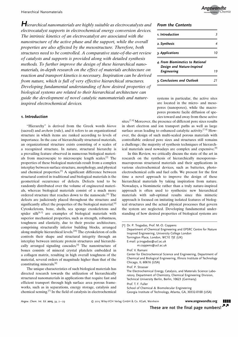
network structure consisting of homogeneous macropores (2–4 mm); the macroscopic channels are parallel to each otherand perpendicular to the tangent of the surface of the particle(Figure 16 a,b).[85] At higher calcination temperatures
(500 8C), however, the mesoporous structure of TiO2 ispartially destroyed and the size of macropores is decreasedto 1–2 mm (Figure 16 c,d);[83d, 86] further calcination above600 8C leads to the destruction of the meso/macroporousstructure (Figure 16e,f). Photodegradation of ethylene in gas-phase medium has been employed to evaluate the activity ofmeso/macroporous TiO2. This TiO2 photocatalyst, calcined at350 8C, demonstrates 60 % higher photoactivity than com-mercial P25 TiO2,
[83d] while further heating above 600 8Cresults in a dramatic loss in photoactivity.[83d]
Another form of hierarchical TiO2 is mesoporous TiO2
film with ordered pores, which is an ideal host matrix forembedding metal nanoparticles, due to its tunable pores andlarge surface area.[78b,f,g,83f–h, 87] The small size of the mesopores(nanometers), though, hinders the effective diffusion oforganic molecules through the pores, as a large fraction ofthe internal surface is excluded.[77] To circumvent this issue,a hierarchically porous structure containing large porechannels is built within the mesoporous film, leading toincreased diffusivity of reactants and products within the film,as well as utilization of a larger internal surface area.[67b, 88] Itstill remains a challenge to independently control the porosityat each length scale to minimize the loss of surface area, andquantitative information in these studies is largely absent,precluding truly rational design.[88a, 89]
Composites of hierarchically ordered meso/macroporousTiO2 films over graphene with 2D hexagonal mesostructures
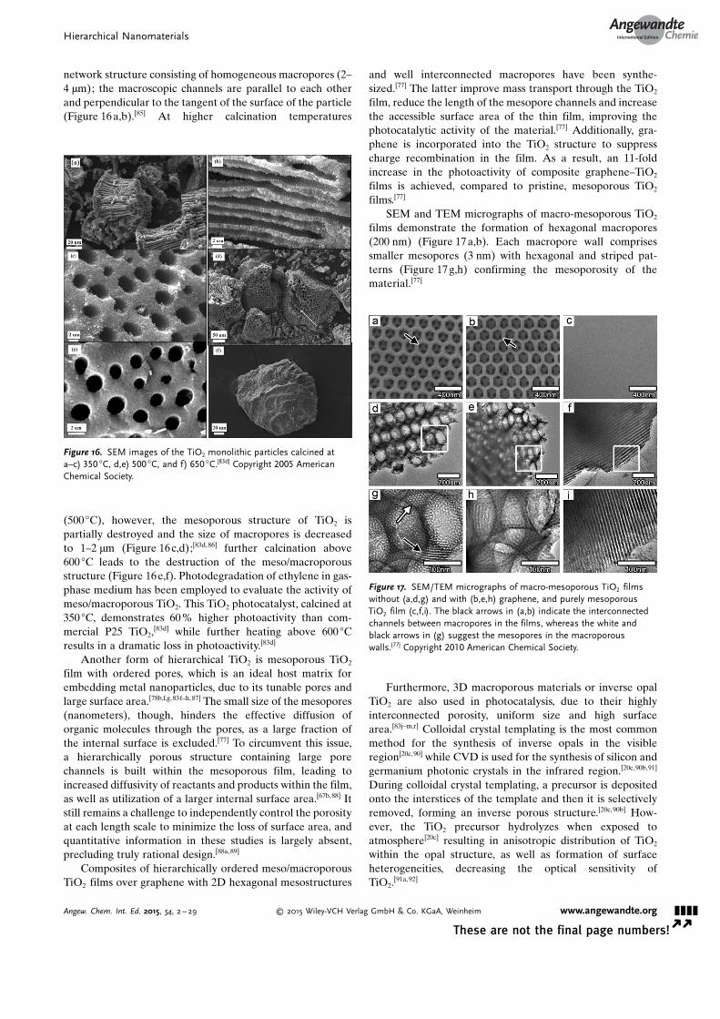
and well interconnected macropores have been synthe-sized.[77] The latter improve mass transport through the TiO2
film, reduce the length of the mesopore channels and increasethe accessible surface area of the thin film, improving thephotocatalytic activity of the material.[77] Additionally, gra-phene is incorporated into the TiO2 structure to suppresscharge recombination in the film. As a result, an 11-foldincrease in the photoactivity of composite graphene–TiO2
films is achieved, compared to pristine, mesoporous TiO2
films.[77]
SEM and TEM micrographs of macro-mesoporous TiO2
films demonstrate the formation of hexagonal macropores(200 nm) (Figure 17 a,b). Each macropore wall comprisessmaller mesopores (3 nm) with hexagonal and striped pat-terns (Figure 17 g,h) confirming the mesoporosity of thematerial.[77]
Furthermore, 3D macroporous materials or inverse opalTiO2 are also used in photocatalysis, due to their highlyinterconnected porosity, uniform size and high surfacearea.[83j–m,r] Colloidal crystal templating is the most commonmethod for the synthesis of inverse opals in the visibleregion[20c,90] while CVD is used for the synthesis of silicon andgermanium photonic crystals in the infrared region.[20c,90b,91]
During colloidal crystal templating, a precursor is depositedonto the interstices of the template and then it is selectivelyremoved, forming an inverse porous structure.[20c,90b] How-ever, the TiO2 precursor hydrolyzes when exposed toatmosphere[20c] resulting in anisotropic distribution of TiO2
within the opal structure, as well as formation of surfaceheterogeneities, decreasing the optical sensitivity ofTiO2.
[91a, 92]
Figure 16. SEM images of the TiO2 monolithic particles calcined ata–c) 350 8C, d,e) 500 8C, and f) 650 8C.[83d] Copyright 2005 AmericanChemical Society.
Figure 17. SEM/TEM micrographs of macro-mesoporous TiO2 filmswithout (a,d,g) and with (b,e,h) graphene, and purely mesoporousTiO2 film (c,f,i). The black arrows in (a,b) indicate the interconnectedchannels between macropores in the films, whereas the white andblack arrows in (g) suggest the mesopores in the macroporouswalls.[77] Copyright 2010 American Chemical Society.
Hierarchical NanomaterialsAngewandte
Chemie
&&&&Angew. Chem. Int. Ed. 2015, 54, 2 – 29 � 2015 Wiley-VCH Verlag GmbH & Co. KGaA, Weinheim www.angewandte.org
These are not the final page numbers! � �
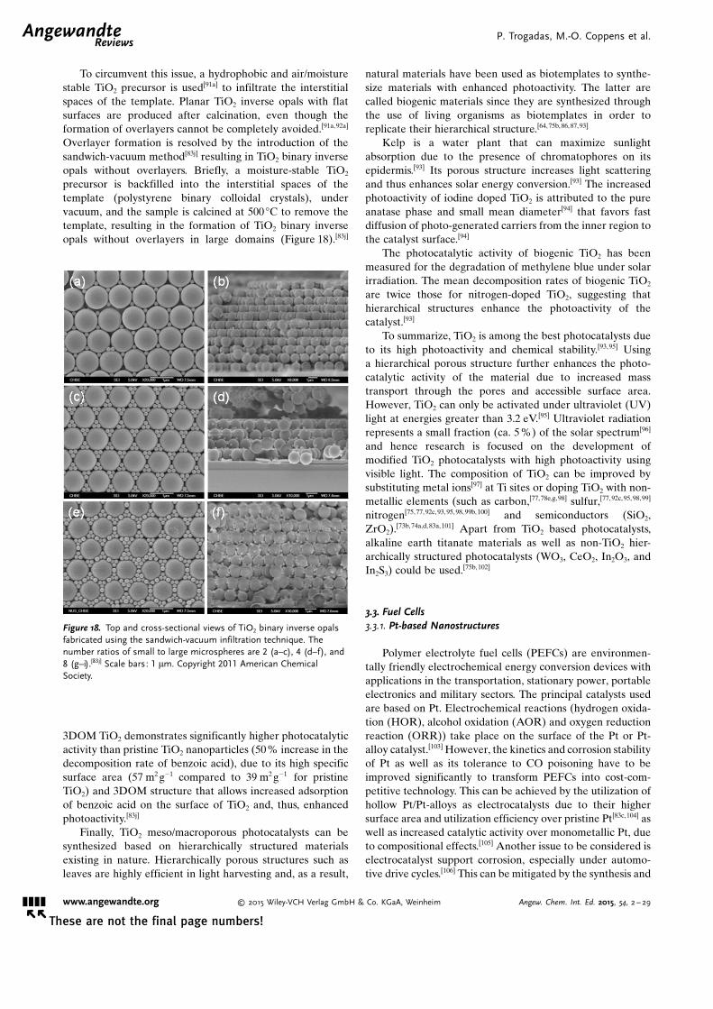
To circumvent this issue, a hydrophobic and air/moisturestable TiO2 precursor is used[91a] to infiltrate the interstitialspaces of the template. Planar TiO2 inverse opals with flatsurfaces are produced after calcination, even though theformation of overlayers cannot be completely avoided.[91a,92a]
Overlayer formation is resolved by the introduction of thesandwich-vacuum method[83j] resulting in TiO2 binary inverseopals without overlayers. Briefly, a moisture-stable TiO2
precursor is backfilled into the interstitial spaces of thetemplate (polystyrene binary colloidal crystals), undervacuum, and the sample is calcined at 500 8C to remove thetemplate, resulting in the formation of TiO2 binary inverseopals without overlayers in large domains (Figure 18).[83j]
3DOM TiO2 demonstrates significantly higher photocatalyticactivity than pristine TiO2 nanoparticles (50 % increase in thedecomposition rate of benzoic acid), due to its high specificsurface area (57 m2 g�1 compared to 39 m2 g�1 for pristineTiO2) and 3DOM structure that allows increased adsorptionof benzoic acid on the surface of TiO2 and, thus, enhancedphotoactivity.[83j]
Finally, TiO2 meso/macroporous photocatalysts can besynthesized based on hierarchically structured materialsexisting in nature. Hierarchically porous structures such asleaves are highly efficient in light harvesting and, as a result,
natural materials have been used as biotemplates to synthe-size materials with enhanced photoactivity. The latter arecalled biogenic materials since they are synthesized throughthe use of living organisms as biotemplates in order toreplicate their hierarchical structure.[64, 75b, 86,87, 93]
Kelp is a water plant that can maximize sunlightabsorption due to the presence of chromatophores on itsepidermis.[93] Its porous structure increases light scatteringand thus enhances solar energy conversion.[93] The increasedphotoactivity of iodine doped TiO2 is attributed to the pureanatase phase and small mean diameter[94] that favors fastdiffusion of photo-generated carriers from the inner region tothe catalyst surface.[94]
The photocatalytic activity of biogenic TiO2 has beenmeasured for the degradation of methylene blue under solarirradiation. The mean decomposition rates of biogenic TiO2
are twice those for nitrogen-doped TiO2, suggesting thathierarchical structures enhance the photoactivity of thecatalyst.[93]
To summarize, TiO2 is among the best photocatalysts dueto its high photoactivity and chemical stability.[93,95] Usinga hierarchical porous structure further enhances the photo-catalytic activity of the material due to increased masstransport through the pores and accessible surface area.However, TiO2 can only be activated under ultraviolet (UV)light at energies greater than 3.2 eV.[95] Ultraviolet radiationrepresents a small fraction (ca. 5 %) of the solar spectrum[96]
and hence research is focused on the development ofmodified TiO2 photocatalysts with high photoactivity usingvisible light. The composition of TiO2 can be improved bysubstituting metal ions[97] at Ti sites or doping TiO2 with non-metallic elements (such as carbon,[77, 78e,g,98] sulfur,[77,92c,95, 98,99]
nitrogen[75,77, 92c,93,95, 98, 99b,100] and semiconductors (SiO2,ZrO2).[73b,74a,d, 83a,101] Apart from TiO2 based photocatalysts,alkaline earth titanate materials as well as non-TiO2 hier-archically structured photocatalysts (WO3, CeO2, In2O3, andIn2S3) could be used.[75b, 102]
3.3. Fuel Cells3.3.1. Pt-based Nanostructures
Polymer electrolyte fuel cells (PEFCs) are environmen-tally friendly electrochemical energy conversion devices withapplications in the transportation, stationary power, portableelectronics and military sectors. The principal catalysts usedare based on Pt. Electrochemical reactions (hydrogen oxida-tion (HOR), alcohol oxidation (AOR) and oxygen reductionreaction (ORR)) take place on the surface of the Pt or Pt-alloy catalyst.[103] However, the kinetics and corrosion stabilityof Pt as well as its tolerance to CO poisoning have to beimproved significantly to transform PEFCs into cost-com-petitive technology. This can be achieved by the utilization ofhollow Pt/Pt-alloys as electrocatalysts due to their highersurface area and utilization efficiency over pristine Pt[83c,104] aswell as increased catalytic activity over monometallic Pt, dueto compositional effects.[105] Another issue to be considered iselectrocatalyst support corrosion, especially under automo-tive drive cycles.[106] This can be mitigated by the synthesis and
Figure 18. Top and cross-sectional views of TiO2 binary inverse opalsfabricated using the sandwich-vacuum infiltration technique. Thenumber ratios of small to large microspheres are 2 (a–c), 4 (d–f), and8 (g–i).[83j] Scale bars: 1 mm. Copyright 2011 American ChemicalSociety.
.AngewandteReviews
P. Trogadas, M.-O. Coppens et al.
&&&& www.angewandte.org � 2015 Wiley-VCH Verlag GmbH & Co. KGaA, Weinheim Angew. Chem. Int. Ed. 2015, 54, 2 – 29� �
These are not the final page numbers!

use of corrosion-resistant metal oxide supports and derivativeelectrocatalysts.[107]
Pure hollow Pt nanoparticles synthesized by a galvanicreplacement reaction (using different sacrificial templates)exhibited significantly higher activity than pristine Pt towardsthe ORR and MOR reactions.[104d, 108] The pronounced differ-ence in activity is directly related to the available surfacearea; both the inner and outer surface of Pt hollow nano-particles participate in the catalytic reaction, whereas only theouter surface of Pt nanoparticles is used in the reactionresulting in a ca. 2-fold increase in available surface area ofhollow Pt nanoparticles.[104d, 109] Additionally, the enhanced Ptmass activity is stable during extended potential cycling(10 000 cycles between 0.65 and 1.05 V vs. RHE at50 mVs�1);[36n] no ECA and ORR/MOR losses were observedand the mass activity of hollow Pt nanoparticles was 6-foldhigher than Pt nanoparticles after 100 h of durability testing(0.6 mAmg�1 and 0.1 mAmg�1, respectively).[36n]
Apart from hollow Pt nanoparticles, hollow Pt-alloys(PtM, M = Au, Ag, Co, Ni, Ru, Pd, Cu) are also used aselectrocatalysts in PEFCs due to their enhanced activity andstability in PEFCs, compared to pure Pt.[105b–v,110] The galvanicreplacement reaction is the most common method tosynthesize these hollow nanoparticles, since it allows easycontrol of the shape and size of the product by varying shapeof the sacrificial template and the ratio of surfactant/reductant as discussed in section 1.4.[39f, 110b,l]
Raspberry-like hierarchical Au/Pt hollow spheres(RHAHS) exhibit higher oxygen reduction peak potential(0.46 V compared to 0.1 V vs. Ag/AgCl) than pristine Aunanoparticles[111] and probe the 4-electron reduction of water;their mass activity was 8 and 4 times higher than Pt/C at 0.595and 0.465 V (vs. SHE), respectively (Figure 19).[103a] HollowPt/Au spheres are also used in direct formic acid fuel cells,increasing the catalytic activity and the tolerance to COpoisoning through ensemble effects.[105a, 112]
Hollow Ni1�xPtx nanospheres exhibit higher catalyticactivity towards methanol oxidation than commercial Pt/Cand solid PtNi nanoparticles.[36n,110g,113] Chronoamperometrymeasurements at constant potential (0.45 V vs. SCE) revealthe high activity of hollow PtNi nanospheres towards MOR,since their oxidation current density is significantly higherthan Pt/C (200 mAmg�1 and 50 mAmg�1, respectively) due tothe high surface area of the hollow structure and the change inPt electronic structure after the addition of Ni.[113a] Ni0
occupies the Pt lattice and the metallic grains are intermixedwith amorphous Ni hydroxides such as Ni(OH)2 andNiOOH.[113a] The presence of these Ni oxides results in theincrease of Pt0 and decrease of PtIV content, due to theelectronic effect of Ni on Pt and, thus, a higher catalyticactivity of PtNi.[113a] Moreover, Ni hydroxides can offer OHspecies to remove the intermediate CO that strongly adsorbson the Pt surface, regenerate the Pt active sites for methanoladsorption,[114] and thus improve the catalytic activity of thenanospheres.
3.3.2. Nanostructures based on Other Noble Metals
Hollow non-Pt alloys have been mainly used for theelectrochemical oxidation of formic acid.[115] In particular, Pdcatalysts possess higher activity in formic acid oxidation thanPt based catalysts.[115, 116] Small Pd particles (9–11 nm) exhibitthe highest binding energy shift and valence band centerdownshift with respect to the Fermi level, resulting ina decrease in the bond strength of the adsorbents[117] and,thus, higher formic acid reactivity.[116] The low d-band centerof small Pd nanoparticles allows them to bind less stronglywith the COOH intermediate than larger Pd nanoparticles,thus reducing the surface (COOH)ads coverage [Eqs. (4) and
Figure 19. A,B) TEM image of TiO2 precursor spheres at differentmagnifications. C,D) TEM images of TiO2 (precursor sphere)/Auhybrid spheres at different magnifications.[103a] E) CVs of CPB (line a)-and RHAHS (line b)-modified GC electrode (5 mm) in a N2-sparged0.5m H2SO4 solution; F) CVs of O2 reduction at RHAHS-modified goldelectrode (lines b and c) and bare gold electrode (line a) in air-saturated (lines a and c) and N2-saturated (line b) 0.5m H2SO4
solution; G) Current–potential curves for the reduction of O2 ata rotating platinum ring-GC (5 mm) disk electrode with RHAHSadsorbed on the disk electrode in the presence of air (experimentalconditions: 1 V constant ring potential, 500 rpm rotation rate,50 mVs�1 scan rate, 0.5m H2SO4 solution).[103a] Copyright 2009 Ameri-can Chemical Society.
Hierarchical NanomaterialsAngewandte
Chemie
&&&&Angew. Chem. Int. Ed. 2015, 54, 2 – 29 � 2015 Wiley-VCH Verlag GmbH & Co. KGaA, Weinheim www.angewandte.org
These are not the final page numbers! � �

(5)].[116] As a result, the rate-determining step [Eq. (5)] can beavoided and a higher rate of HCOOH decomposition to CO2
is achieved [Eq. (3)].[116]
HCOOHbulk ! 2 Hþ þ 2 e� þ CO2 ð3Þ
HCOOHads ! ðCOOHÞads þHþ þ e� ð4Þ
ðCOOHÞadsrds�! CO2 þHþ þ e� ð5Þ
To further improve the catalytic activity of Pd, Pd–Malloys (M = Au, Rh, Cu, Ag) with hollow/core–shell structureare used due to their high surface area and the modulatedelectron structure.[110s,118]
For example, hollow Pd/Au nanospheres demonstratehigher activity towards formic acid oxidation than pristine Pdand Au nanoparticles due to their increased surface to volumeratio;[118c] the raspberry surface of Au nanospheres containsirregular Pd grains, which increase the surface-to-volumeratio and surface activity of the Pd/Au catalyst.[118c] Similarresults are observed in the case of hollow Pd/Cu and Pd/Agnanospheres.[118a, 119] Hollow Pd/Ag nanotubes have a single-layer crystalline structure comprised of Ag {1,1,1} and Pd{1,1,1} planes with six-fold rotational symmetry resulting ina 2-fold increase of catalytic activity compared to pristine Pdand a high tolerance to CO poisoning, as evidenced by theshift of the onset potential for formic acid oxidation towardsmore positive values.[118b]
3.3.3. Hierarchical Catalyst Supports
The activity and stability of electrocatalysts is closelyrelated to the catalysts support.[120] Carbon black (Vulcan XC-72) is the most common support used in fuel cells, due to itslarge surface area, high electrical conductivity and porousstructure.[120b] However, carbon is susceptible to the corrosiveenvironment of PEMFCs, leading to the oxidation of carbonsupports and to the detachment and agglomeration of Ptnanoparticles and, thus, to fuel cell performance and ECAlosses.[120b] Specifically, carbon is readily (and irreversibly)oxidized to carbon dioxide at the high overpotentialsencountered at the cathode (during the fuel–air transientsthat occur during automobile start-up and shut down) and atthe anode (during fuel starvation).[106]
As a result, different forms of nanoporous carbonmaterials (carbon nanotubes, nanofibers and mesoporouscarbon) as well as non-carbon electrocatalyst supports havebeen investigated.[46c,120a, 121] They have to meet the followingcriteria in order to be considered as viable options: 1) highsurface area; 2) porosity; 3) high electrical conductivity and4) stability under fuel cell conditions (especially potentialtransients).
A promising catalyst support is well-aligned carbonnanotubes (WCNTs), providing high catalyst dispersionbetween nanotubes.[46c,121e] The energy required for ORRactivation is smaller for Pt/WCNTs compared to Pt supportedon Vulcan XC-72 Carbon; thus, Pt/WCNTs exhibit improvedORR kinetics.[121e] Similar results are obtained for the energyrequired for MOR activation,[46c] indicating that Pt/WCNTshave enhanced MOR kinetics over Pt/C.
Carbon nanofibers (CNFs) are also used as catalystsupports in PEFCs[120a, 121a–d] in three different structures:fishbone, deck of cards, and parallel.[122] The CNFs withfishbone morphology (f-CNF) have graphene layers witha 458 angle to the growth axis, while CNFs with deck of cardsmorphology (platelet, p-CNF) have graphene layers perpen-dicular to the growth axis (Figure 20). CNFs with parallelmorphology (tubular, t-CNF) have graphene layers parallel tothe growth axis, with a multiwall ensemble.[122b]
CVs in oxygen saturated HClO4 (0.5m) reveal that p-CNFhas the most positive ORR peak potential and, hence, thehighest ORR activity (Table 2), due to the higher ratio ofedge to basal atoms in p-CNFs.[123] With regard to peakcurrent, p-CNFs have a lower ORR current than f-CNFs, dueto the smaller particle size of f-CNFs (60 nm compared to100 nm for p-CNFs) and, thus, a higher active site density.[123]
These different CNF structures are also used as supportsfor PtRu catalysts in DMFCs.[124] Platelet CNFs exhibit thehighest catalytic activity towards methanol oxidation, fol-lowed by tubular and herringbone CNFs (90, 60, and50 mW cm�2, respectively).[124] These values are 2–3 timeshigher than the measured PtRu/carbon black(30 mW cm�2).[124]
The difference in CNF nanostructure causes preferentiallocalization of metal nanoparticles.[125] Metal nanoparticlesare dispersed on the edge of the graphite layers (Figure 21 A)in the case of p-CNFs, in the tubes and on the surface for t-CNFs (Figure 21C), and between the layers and on the edgefor h-CNFs (Figure 21B). Thus, the nanostructure of CNFsinfluences the dispersion and reactivity of supported nano-
Figure 20. Schematic representation of three types of CNFs. Based onRef. [122b].
Table 2: ORR peak potential and current of different CNF electrodes(0.5m HClO4, 100 mVs�1).[123]
Sample Peak potential [V] Peak current [mA]
f-CNF �0.27 �0.128p-CNF �0.25 �0.064t-CNF �0.38 �0.048Graphite �0.48 �0.038
.AngewandteReviews
P. Trogadas, M.-O. Coppens et al.
&&&& www.angewandte.org � 2015 Wiley-VCH Verlag GmbH & Co. KGaA, Weinheim Angew. Chem. Int. Ed. 2015, 54, 2 – 29� �
These are not the final page numbers!
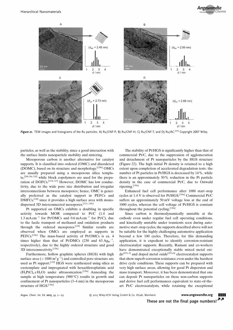
particles, as well as the stability, since a good interaction withthe surface limits nanoparticle mobility and sintering.
Mesoporous carbon is another alternative for catalystsupports. It is classified into ordered (OMC) and disordered(DOMC), based on its structure and morphology.[120b] OMCsare usually prepared using a mesoporous silica templa-te,[26b,28a, 126] while block copolymers are used for the prepa-ration of DOFCs.[121b, 127] However, DOMC has low conduc-tivity, due to the wide pore size distribution and irregularinterconnections between mesopores; hence, OMC is gener-ally preferred as the catalyst support in PEFCs andDMFCs,[128] since it provides a high surface area with mono-dispersed 3D interconnected mesopores.[121c,128c]
Pt supported on OMCs exhibits a doubling in specificactivity towards MOR compared to Pt/C (1.4 and1.3 mAcm�2 for Pt/OMCs and 0.6 mAcm�2 for Pt/C), dueto the facile transport of methanol and oxidation productsthrough the ordered mesopores.[129] Similar results areobserved when OMCs are employed as supports inPEFCs.[128c] The mass-based activity of Pt/OMCs is ca. 4times higher than that of Pt/DMCs (230 and 63 AgPt
�1,respectively), due to the highly ordered structure and good3D interconnectivity.[128c]
Furthermore, hollow graphitic spheres (HGS) with highsurface area (> 1000 m2 g�1) and controlled pore structure areused as Pt support.[130] HGS were synthesized using silica asexotemplate and impregnated with hexachloroplatinic acid(H2PtCl6·xH2O) under ultrasonication.[130a] Annealing thesample at high temperature (900 8C) results in growth andconfinement of Pt nanoparticles (3–4 nm) in the mesoporousstructure of HGS.[130a]
The stability of Pt/HGS is significantly higher than that ofcommercial Pt/C, due to the suppression of agglomerationand detachment of Pt nanoparticles by the HGS structure(Figure 22). The high initial Pt density is retained to a highextent upon completion of accelerated degradation tests: thenumber of Pt particles in Pt/HGS is decreased by 14 %, whilethere is an approximately 50 % reduction in the Pt particledensity in the case of commercial Pt/C, due to Ostwaldripening.[130a]
Enhanced fuel cell performance after 1000 start–stopcycles at 1.4 V is observed for Pt/HGS.[130a] Commercial Pt/Csuffers an approximately 50 mV voltage loss at the end of1000 cycles, whereas the cell voltage of Pt/HGS is constantthroughout the potential cycling.[130a]
Since carbon is thermodynamically unstable at thecathode even under regular fuel cell operating conditions,and kinetically unstable under transients seen during auto-motive start–stop cycles, the supports described above will notbe suitable for the highly challenging automotive applicationbeyond a few 100 cycles. Therefore, for this demandingapplication, it is expedient to identify corrosion-resistantelectrocatalyst supports. Recently, Ramani and co-workershave demonstrated exceptionally stable mixed metal oxi-de[107c–f] and doped metal oxide[107a,b] electrocatalyst supportsthat show superb corrosion resistance even under the harshestdrive cycle conditions. These supports can be prepared withvery high surface areas, allowing for good Pt dispersion andmass transport. Moreover, it has been demonstrated that onecan deposit Pt nanoparticles on these non-carbon supportsand derive fuel cell performances equivalent to state-of-the-art Pt/C electrocatalysts, while retaining the exceptional
Figure 21. TEM images and histograms of the Ru particles: A) Ru/CNF-P, B) Ru/CNF-H, C) Ru/CNF-T, and D) Ru/AC.[125] Copyright 2007 Wiley.
Hierarchical NanomaterialsAngewandte
Chemie
&&&&Angew. Chem. Int. Ed. 2015, 54, 2 – 29 � 2015 Wiley-VCH Verlag GmbH & Co. KGaA, Weinheim www.angewandte.org
These are not the final page numbers! � �

stability of the non-carbon support.[107f] Finally, they haveshown clear evidence (via X-ray absorption spectroscopyexperiments) of electron back-donation from the dopedtitanium oxide support to the platinum nanoparticles, therebyconfirming strong metal–support interactions in this system.Such interactions provide an additional handle to tune andfurther enhance the electrocatalytic activity of platinum.[107b]
In summary, the instability of carbon black undertransient fuel cell conditions, as well as the presence ofmicropores that hinder reactant flow and thus fuel cellperformance, has led to the investigation of alternativecarbon-based catalyst supports, namely mesoporous carbon,well-aligned carbon nanotubes, carbon nanofibers and hollowgraphitic spheres. The high surface area and mesoporosity ofthese materials allows for high catalyst dispersion andreactant flow, leading to increased catalytic activity towardsMOR and ORR. However, even these supports will not beadequately stable for automotive applications. For thisapplication, a series of non-carbon metal oxide basedsupports have been synthesized, and the resultant catalystswere demonstrated to possess exceptional stability andtunable activity. Further improvements to the structure ofthese alternative carbon supports can be achieved byimplementing hierarchical macro/mesoporous structuresinspired by those present in nature, as discussed in Section 4.
3.3.4. Support-less Hybrid Metallic Aerogels
Recently, research has been focused on the synthesis andutilization of support-less hybrid aerogels of metal nano-particles (such as Pd, Pt, Au and Ag) as catalysts for theethanol and oxygen reduction reaction.[45] Hybrid Pd aerogelsdemonstrated superior catalytic activity towards ethanol andoxygen reduction and high durability. The current density ofthe forward oxidation of ethanol was approximately twice thedensity of Pd/C due to the high porosity of the hybrid aerogelfavoring the exposure of catalytic active sites,[45b] whereas thestability of hybrid Pd aerogels was approximately 6 timeshigher than Pd/C after a 4 h durability testing.[45b]
Similar results were obtained when hybrid bimetallic PtPdaerogels were used as catalysts towards ORR.[45c] PtPdaerogels with higher than 40 wt % Pt content meet orexceed the performance target for ORR fuel cell catalysts(0.44 AmgPt
�1 Pt at 0.9 V vs. RHE, 80 8C) set by the U.S.Department of Energy. The enhanced catalytic activity isattributed to the high porosity and the existence of mesoporeswider than 25 nm in PtPd aerogels, which avoids Knudsendiffusion limitations and thus decreases the diffusion resist-ance in the catalyst layer.[45c] In terms of stability (massactivity measurement after 10000 potential cycles between 0.5and 1 V vs. SHE), Pt80Pd20 (12% loss) and Pt40Pd60 (36%increase) hybrid aerogels exhibit significantly higher durabil-ity than Pt aerogel and commercial Pt/C (54% and 56 % lossrespectively), indicating that the existence of Pd stabilizes thecatalyst (Figure 23). The observed increase in mass activity inthe case of Pd-rich aerogel (Pt40Pd60) is due to the de-alloyingof Pd upon potential cycling such that it slowly approaches thebehavior of the Pt-rich aerogel alloys.[45c]
Hence, support-less hybrid metallic aerogels constitutea new class of fuel cell electrocatalysts combining highcatalytic activity with high stability. Even though the prelimi-nary results are very promising, extensive research is neededto broaden the range of metal nanoparticles that can be used
Figure 22. Identical location-SEM/STEM micrographs of Pt/HGS after0 and after 3600 electrochemical degradation cycles: a) overlap of highresolution SEM (green) and dark field STEM (red) of a representativePt/HGS particle; b) high resolution SEM of a region in the middle ofthe Pt/HGS particle highlighted with a white square; c) simultaneouslytaken dark field STEM micrograph; d–f) correspond to identicallocations after electrochemical degradation. Yellow arrows point atpores and green circles at Pt nanoparticles placed at the externalsurface of the HGS support.[130a] Copyright 2012 American ChemicalSociety.
Figure 23. Relative ORR mass activity of PtxPdy catalysts of differentcompositions as a function of the number of potential cycles (0.5 V to1.0 V). The mass activity was obtained from the cathodic scan of ORRpolarization curves (corrected for electrolyte resistances) at 10 mVs�1
and 1600 rpm.[45c] Copyright 2013 Wiley.
.AngewandteReviews
P. Trogadas, M.-O. Coppens et al.
&&&& www.angewandte.org � 2015 Wiley-VCH Verlag GmbH & Co. KGaA, Weinheim Angew. Chem. Int. Ed. 2015, 54, 2 – 29� �
These are not the final page numbers!

in aerogels, and to investigate the mechanism of gel formationand thus be able to accurately control the porosity and surfacearea of the hybrid aerogels. Also, simple, cost-effectivesynthesis methods need to be developed in order to makehybrid aerogel synthesis scalable.
4. From Biomimetics to Rational Design andNature-Inspired Engineering
Hierarchical structures are omnipresent in biology, fromprotein complexes at the nanoscale, to the inherently scalablestructure of organs and biological transport networks, and upto the macroscopic scale of entire organisms and biologicalcommunities.[3,8b,c,131] These hierarchical structures are oftennot coincidental, yet, rather, relate to the multi-objectiveoptimization of different biological functions, and adaptabil-ity under growth as well as under perturbations, for example,to cope with changing environmental conditions.[8b,c]
Manmade designs that copy features of biological struc-tures to achieve similar properties are often referred to as“bio-mimetic” (derived from the Greek word mimesis). Whilespurring innovation, many such biomimetic designs neglectthe issue that the constraints in technological applications arenot necessarily the same as in biological systems, or thata natural structure is not optimal under all conditions.Relevant timescales are different, available material resour-ces differ, the objectives could be different, and thermody-namics might tell us that the best temperature or pressure isnot the physiological one of the model biological system.
We therefore advocate a broader, nature-inspired chem-ical engineering (NICE) approach, as one that takes guidancefrom nature for design. The NICE approach translatesfundamental mechanisms behind desirable properties innatural systems (such as scalability, efficiency or robustness)to technological applications, within the context and underthe constraints of these applications. Rather than superficialanalogies, fundamental physics are taken as a basis forrational design.[8b,c,132]
After discussing some biomimetic approaches to fuel celldesign, we discuss rational design principles and earlyapplications and opportunities of the nature-inspired engi-neering approach, developed by Coppens and co-workers.
4.1. Biomimetics
Several biomimetic approaches have been used so far todesign PEFC flow fields based on the structure of leaves andlungs.[133] These biomimetic designs combine serpentine andinterdigitated patterns to avoid water flooding and increasethe power density of the fuel cell (Figure 24).[133b, c] Simulationstudies using a thick gas diffusion layer (GDL 1.02 mm) withhigh permeability show that the incorporation of biomimeticflow field designs result in a lower pressure drop from theinlet to the outlet than the commercial serpentine/interdigi-tated design (26 and 40 Pa pressure loss, respectively) andmore uniform pressure distribution.[133b] Experimental vali-dation of the theoretical results at various operating con-
ditions show that the biomimetic flow fields increase the peakpower density and overall fuel cell performance by 30%.[133b,c]
However, additional experimental evaluation of thesedesigns is necessary in order to validate fuel cell performanceand scalability of the system under extensive fuel celloperation. An essential shortcoming of these biomimeticdesigns is the lack of a rigorous theoretical motivation tosupport them. Even though the inspirational source is clear,the absence of an underlying theory makes it difficult to testalternative designs, as there is no theoretical basis to compareagainst. Interesting fundamental properties of the pulmonaryarchitecture, such as the fractal structure of the bronchial tree,which is tied to its scalability and efficiency,[8i, 134] are notutilized.
4.2. Modeling
Computational modeling has been extensively employedto study the effect of operational parameters as well as cellcomponents on fuel-cell performance,[58s, 135] without account-ing for the structure of the material. Many numerical modelshave been developed with increasingly less restrictiveassumptions and more physical complexities to providesolutions for the equations that incorporate the electrochem-ical kinetics and thermodynamics, as well as heat, mass,charge and momentum transport.[58s,135, 136] A brief and by nomeans comprehensive overview is provided in SupportingInformation; it is clear that further development of multi-scale modeling approaches is required to account for not onlythe steady state, but also the dynamics of the complex, multi-phase phenomena occurring in electrocatalysts and fuel cells.This is especially so in view of the tremendous progress incapabilities to synthesize hierarchically structured nanoma-terials; these experimental synthetic capabilities can only betruly taken advantage of if they are complemented bysimulations that allow to interpret experiments, and guidethe engineering of better electrochemical devices.
Figure 24. a) Leaf- and b) lung-inspired, biomimetic flow field designs.The inlet is at the top and the outlet is at the bottom.[133b] Reprintedfrom Ref. [133b] with permission from Elsevier.
Hierarchical NanomaterialsAngewandte
Chemie
&&&&Angew. Chem. Int. Ed. 2015, 54, 2 – 29 � 2015 Wiley-VCH Verlag GmbH & Co. KGaA, Weinheim www.angewandte.org
These are not the final page numbers! � �

4.3. Rational Design Guided by Nature-Inspired Engineering
Even though Pt is a highly efficient electrocatalyst forPEFCs, the high cost of this material dictates the use of low Ptloading or novel nanostructured Pt or Pt alloy-based catalysts.A nature-inspired chemical engineering (NICE) approachcan aid towards achieving the low Pt loading target bymodifying the PEFC design, guided by the hierarchicalstructure of the lung.[8c] Nature-inspired engineeringresearches the fundamental mechanism underlying a desiredproperty or function in nature and applies this mechanism ina technological context.[8c]
The respiratory tract of a mammalian lung has a self-similar, fractal structure consisting of many generations ofbranches (14–16 for the adult human lung), from the tracheato the bronchioles, in which flow dominates transport,followed by generations of space-filling acini lined by alveoliin which diffusion dominates transport.[137] Entropy produc-tion while breathing is uniformly distributed and globallyminimized in both regimes,[8i, 134, 137] a very desirable propertyfrom the point of view of thermodynamic efficiency.[138] Thefractal architecture of the upper part of the lung, which issimilar to a tree,[139] connects multiple microscopic elementsto a single macroscopic element via equal hydraulic pathlengths providing equal transport rates to or from the cells.[8c]
A great advantage of this fractal structure is its scalability. Thefractal network can be broadened by adding a generation,while keeping the structure of the microscopic building unitsthe same (Figure 25).[8b]
These observations, already successfully applied to fractalinjectors in multiphase reactors, such as fluidized beds,[8b,140]
can be used as a building principle for fuel-cell design as well.Figure 26 shows a two-dimensional fractal distributor built in-house, by rapid prototyping or stereo-lithography. Air oroxygen enters the distributor through a single inlet; it flowsthrough the branching channels and eventually exits thedistributor through a square array of outlets, which have the
same hydraulic distance from the inlet. As a result, this fractaldistributor uniformly feeds reactants (O2/air) to the catalystlayer, while produced water is removed via an embeddedcollector, circumventing the non-uniformity issues of otherflow-field geometries. Fuel cell performance measurementsare currently under way.
Murray�s law can be used to design fractal distributors.[141]
Murray found, for vascular networks, that the flow of bloodpast any section should bear the same relation to the cube ofthe radius of the vessel at that point. By derivation, the cubeof the radius of the parent vessel must be equal to the sum ofthe cubes of the radii of the daughter vessels. An extendedMurray�s law [Eq. (6)] is obeyed in the vascular andpulmonary systems of animals, as well as in the xylemstructures of plants[133a, 142]:
rDp ¼ rD
d1 þ rDd2 þ :::þ rD
dn ð6Þ
where rp is the radius of the parent vessel, rd1, …, rdn are theradii of the daughter vessels and D the diameter exponent (forexample, D = 2 for many botanical trees, D = 2.7 for thearteries and D = 3 for the lung).[143]
Murray�s law has been used to develop non-fractal flowfield designs as well (Figure 27), to address the issue of non-uniform current density distribution across a fuel cell.[142a] Theside branches are connected directly to a side channel that isgradually increasing in width as more branches are attachedaccording to Murray�s law.[142a]
The depicted flow field exhibits lower pressure drop thanserpentine designs and, hence, reduces the parasitic loadrequired to pump fuel/oxidant gas.[142a] However, this flowfield does not display inherent fractal scalability and wasobserved to be prone to flooding during fuel-cell operation ata low temperature (70 8C, 100 %RH). This issue could beresolved if the fuel cell was operated at high temperatures(> 100 8C) and low relative humidities where the water isalways in the vapor phase, and the improved mass transfer
Figure 25. A) A set of 1D distributors feeding progressively larger 1D arrays (vectors). B,C) Extension of the scalable, fractal distributor concept to2D and 3D, respectively.
.AngewandteReviews
P. Trogadas, M.-O. Coppens et al.
&&&& www.angewandte.org � 2015 Wiley-VCH Verlag GmbH & Co. KGaA, Weinheim Angew. Chem. Int. Ed. 2015, 54, 2 – 29� �
These are not the final page numbers!
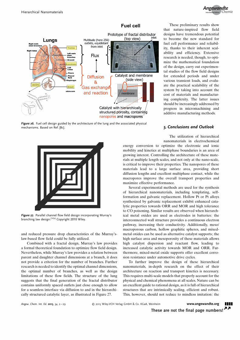
and reduced pressure drop characteristics of the Murray�s-law-based flow field could be fully utilized.
Combined with a fractal design, Murray�s law providesa formal theoretical foundation to optimize flow field design.Nevertheless, while Murray�s law provides a relation betweenparent and daughter channel dimensions at a branch, it doesnot provide a criterion for the number of branches. Furtherresearch is needed to identify the optimal channel dimensions,the optimal number of branches, as well as the designlimitations of these flow fields. The structure of the lungsuggests that the final generation of the fractal distributorcontains uniformly spaced outlets just close enough to allowfor a seamless interface via diffusion to and in the hierarchi-cally structured catalytic layer, as illustrated in Figure 27.
These preliminary results showthat nature-inspired flow fielddesigns have tremendous potentialto become the new standard forfuel cell performance and reliabil-ity, thanks to their inherent scal-ability and efficiency. Extensiveresearch is needed, though, to opti-mize the mathematical foundationof the design, carry out experimen-tal studies of the flow field designsfor extended periods and undervarious transient loads, and evalu-ate the practical scalability of thesystem by taking into account thecost of materials and manufactur-ing complexity. The latter issuesshould be increasingly addressed byprogress in micromachining andadditive manufacturing methods.
5. Conclusions and Outlook
The utilization of hierarchicalnanomaterials in electrochemical
energy conversion to optimize the electronic and ionicmobility and kinetics at multiphase boundaries is an area ofgrowing interest. Controlling the architecture of these mate-rials at multiple length scales, and not only at the nano-scale,is critical to improve their properties. The nanopores of thesematerials lead to a large surface area, providing shortdiffusion lengths and excellent multiphase contact, while themacropores improve the overall transport properties andmaximize effective performance.
Several experimental methods are used for the synthesisof hierarchical nanomaterials, including templating, self-formation and galvanic replacement. Hollow Pt or Pt alloyssynthesized by galvanic replacement exhibit enhanced cata-lytic properties towards ORR and MOR and high toleranceto CO poisoning. Similar results are observed when hierarch-ical metal oxides are used as electrodes in batteries: theinterconnected wall structure provides a continuous electronpathway, increasing their conductivity. Additionally, meso/macroporous carbon, hollow graphitic spheres, and mixed-metal oxides can be used as alternative catalyst supports; thehigh surface area and mesoporosity of these materials allowshigh catalyst dispersion and reactant flow, leading toincreased catalytic activity towards MOR and ORR. Fur-thermore, mixed-metal oxide supports offer excellent corro-sion resistance under automotive drive cycles.
To further improve the design of these hierarchicalnanomaterials, in-depth research on the effect of theirarchitecture on reaction and transport kinetics is necessary.This requires multi-scale models that properly account for thephysical and chemical phenomena at all scales. Nature can bean excellent guide to rational design, as it is full of hierarchicalstructures that are intrinsically scaling, efficient and robust.This, however, should not reduce to mindless imitation: the
Figure 26. Fuel cell design guided by the architecture of the lung and the associated physicalmechanisms. Based on Ref. [8c].
Figure 27. Parallel channel flow field design incorporating Murray’sbranching law design.[142a] Copyright 2010 Wiley.
Hierarchical NanomaterialsAngewandte
Chemie
&&&&Angew. Chem. Int. Ed. 2015, 54, 2 – 29 � 2015 Wiley-VCH Verlag GmbH & Co. KGaA, Weinheim www.angewandte.org
These are not the final page numbers! � �
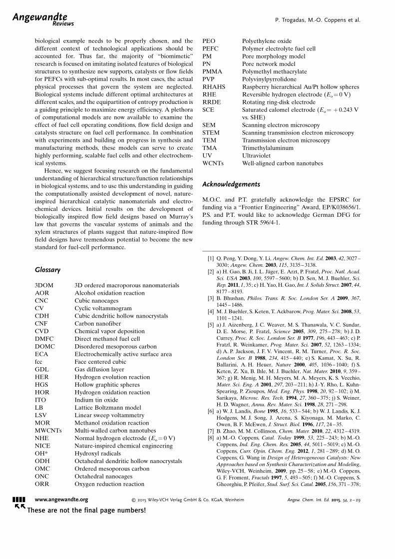
biological example needs to be properly chosen, and thedifferent context of technological applications should beaccounted for. Thus far, the majority of “biomimetic”research is focused on imitating isolated features of biologicalstructures to synthesize new supports, catalysts or flow fieldsfor PEFCs with sub-optimal results. In most cases, the actualphysical processes that govern the system are neglected.Biological systems include different optimal architectures atdifferent scales, and the equipartition of entropy production isa guiding principle to maximize energy efficiency. A plethoraof computational models are now available to examine theeffect of fuel cell operating conditions, flow field design andcatalysts structure on fuel cell performance. In combinationwith experiments and building on progress in synthesis andmanufacturing methods, these models can serve to createhighly performing, scalable fuel cells and other electrochem-ical systems.
Hence, we suggest focusing research on the fundamentalunderstanding of hierarchical structure/function relationshipsin biological systems, and to use this understanding in guidingthe computationally assisted development of novel, nature-inspired hierarchical catalytic nanomaterials and electro-chemical devices. Initial results on the development ofbiologically inspired flow field designs based on Murray�slaw that governs the vascular systems of animals and thexylem structures of plants suggest that nature-inspired flowfield designs have tremendous potential to become the newstandard for fuel-cell performance.
Glossary
3DOM 3D ordered macroporous nanomaterialsAOR Alcohol oxidation reactionCNC Cubic nanocagesCV Cyclic voltammogramCDH Cubic dendritic hollow nanocrystalsCNF Carbon nanofiberCVD Chemical vapor depositionDMFC Direct methanol fuel cellDOMC Disordered mesoporous carbonECA Electrochemically active surface areafcc Face centered cubicGDL Gas diffusion layerHER Hydrogen evolution reactionHGS Hollow graphitic spheresHOR Hydrogen oxidation reactionITO Indium tin oxideLB Lattice Boltzmann modelLSV Linear sweep voltammetryMOR Methanol oxidation reactionMWCNTs Multi-walled carbon nanotubesNHE Normal hydrogen electrode (Eo = 0 V)NICE Nature-inspired chemical engineeringOH* Hydroxyl radicalsODH Octahedral dendritic hollow nanocrystalsOMC Ordered mesoporous carbonONC Octahedral nanocagesORR Oxygen reduction reaction
PEO Polyethylene oxidePEFC Polymer electrolyte fuel cellPM Pore morphology modelPN Pore network modelPMMA Polymethyl methacrylatePVP PolyvinylpyrrolidoneRHAHS Raspberry hierarchical Au/Pt hollow spheresRHE Reversible hydrogen electrode (Eo = 0 V)RRDE Rotating ring-disk electrodeSCE Saturated calomel electrode (Eo = + 0.243 V
vs. SHE)SEM Scanning electron microscopySTEM Scanning transmission electron microscopyTEM Transmission electron microscopyTMA TrimethylaluminumUV UltravioletWCNTs Well-aligned carbon nanotubes
Acknowledgements
M.O.C. and P.T. gratefully acknowledge the EPSRC forfunding via a “Frontier Engineering” Award, EP/K038656/1.P.S. and P.T. would like to acknowledge German DFG forfunding through STR 596/4-1.
[1] Q. Peng, Y. Dong, Y. Li, Angew. Chem. Int. Ed. 2003, 42, 3027 –3030; Angew. Chem. 2003, 115, 3135 – 3138.
[2] a) H. Gao, B. Ji, I. L. J�ger, E. Arzt, P. Fratzl, Proc. Natl. Acad.Sci. USA 2003, 100, 5597 – 5600; b) D. Sen, M. J. Buehler, Sci.Rep. 2011, 1, 35; c) H. Yao, H. Gao, Int. J. Solids Struct. 2007, 44,8177 – 8193.
[3] B. Bhushan, Philos. Trans. R. Soc. London Ser. A 2009, 367,1445 – 1486.
[4] M. J. Buehler, S. Keten, T. Ackbarow, Prog. Mater. Sci. 2008, 53,1101 – 1241.
[5] a) J. Aizenberg, J. C. Weaver, M. S. Thanawala, V. C. Sundar,D. E. Morse, P. Fratzl, Science 2005, 309, 275 – 278; b) J. D.Currey, Proc. R. Soc. London Ser. B 1977, 196, 443 – 463; c) P.Fratzl, R. Weinkamer, Prog. Mater. Sci. 2007, 52, 1263 – 1334;d) A. P. Jackson, J. F. V. Vincent, R. M. Turner, Proc. R. Soc.London Ser. B 1988, 234, 415 – 440; e) S. Kamat, X. Su, R.Ballarini, A. H. Heuer, Nature 2000, 405, 1036 – 1040; f) S.Keten, Z. Xu, B. Ihle, M. J. Buehler, Nat. Mater. 2010, 9, 359 –367; g) R. Menig, M. H. Meyers, M. A. Meyers, K. S. Vecchio,Mater. Sci. Eng. A 2001, 297, 203 – 211; h) J.-Y. Rho, L. Kuhn-Spearing, P. Zioupos, Med. Eng. Phys. 1998, 20, 92 – 102; i) M.Sarikaya, Microsc. Res. Tech. 1994, 27, 360 – 375; j) S. Weiner,H. D. Wagner, Annu. Rev. Mater. Sci. 1998, 28, 271 – 298.
[6] a) W. J. Landis, Bone 1995, 16, 533 – 544; b) W. J. Landis, K. J.Hodgens, M. J. Song, J. Arena, S. Kiyonaga, M. Marko, C.Owen, B. F. McEwen, J. Struct. Biol. 1996, 117, 24 – 35.
[7] B. Zhao, M. M. Collinson, Chem. Mater. 2010, 22, 4312 – 4319.[8] a) M.-O. Coppens, Catal. Today 1999, 53, 225 – 243; b) M.-O.
Coppens, Ind. Eng. Chem. Res. 2005, 44, 5011 – 5019; c) M.-O.Coppens, Curr. Opin. Chem. Eng. 2012, 1, 281 – 289; d) M. O.Coppens, G. Wang in Design of Heterogeneous Catalysts: NewApproaches based on Synthesis Characterization and Modeling,Wiley-VCH, Weinheim, 2009, pp. 25 – 58; e) M.-O. Coppens,G. F. Froment, Fractals 1997, 5, 493 – 505; f) M.-O. Coppens, S.Gheorghiu, P. Pfeifer, Stud. Surf. Sci. Catal. 2005, 156, 371 – 378;
.AngewandteReviews
P. Trogadas, M.-O. Coppens et al.
&&&& www.angewandte.org � 2015 Wiley-VCH Verlag GmbH & Co. KGaA, Weinheim Angew. Chem. Int. Ed. 2015, 54, 2 – 29� �
These are not the final page numbers!

g) S. Gheorghiu, M. O. Coppens, AIChE J. 2004, 50, 812 – 820;h) C. Hou, S. Gheorghiu, M.-O. Coppens, V. H. Huxley, P.Pfeifer, in Fractals in Biology and Medicine, Springer, Berlin,2005, pp. 17 – 30; i) E. Johannessen, G. Wang, M.-O. Coppens,Ind. Eng. Chem. Res. 2007, 46, 4245 – 4256; j) G. Wang, E.Johannessen, C. R. Kleijn, S. W. de Leeuw, M.-O. Coppens,Chem. Eng. Sci. 2007, 62, 5110 – 5116.
[9] a) N. Liu, W. Li, M. Pasta, Y. Cui, Front. Phys. 2014, 9, 323 –350; b) Z.-Y. Yuan, B.-L. Su, J. Mater. Chem. 2006, 16, 663 – 677.
[10] a) D. M. Antonelli, J. Y. Ying, Angew. Chem. Int. Ed. Engl.1996, 35, 426 – 430; Angew. Chem. 1996, 108, 461 – 464; b) A.Sayari, Y. Yang, J. Phys. Chem. B 2000, 104, 4835 – 4839.
[11] a) F. Jiao, P. G. Bruce, Angew. Chem. Int. Ed. 2004, 43, 5958 –5961; Angew. Chem. 2004, 116, 6084 – 6087; b) J. Lee, S. Yoon,T. Hyeon, S. M. Oh, K. Bum Kim, Chem. Commun. 1999,2177 – 2178; c) W.-C. Li, A.-H. Lu, C. Weidenthaler, F. Sch�th,Chem. Mater. 2004, 16, 5676 – 5681.
[12] a) C. Perego, R. Millini, Chem. Soc. Rev. 2013, 42, 3956 – 3976;b) Y. Ye, C. Jo, I. Jeong, J. Lee, Nanoscale 2013, 5, 4584 – 4605;c) S. Meoto, M.-O. Coppens, J. Mater. Chem. A 2014, 2, 5640 –5654; d) R. Pitchumani, J. J. Heiszwolf, A. Schmidt-Ott, M. O.Coppens, Microporous Mesoporous Mater. 2009, 120, 39 – 46;e) J.-K. Sun, Q. Xu, Energy Environ. Sci. 2014, 7, 2071 – 2100.
[13] a) A. Fischer, Y.-S. Jun, A. Thomas, M. Antonietti, Chem.Mater. 2008, 20, 7383 – 7389; b) N. D. Petkovich, A. Stein,Chem. Soc. Rev. 2013, 42, 3721 – 3739; c) A. Stein, S. G.Rudisill, N. D. Petkovich, Chem. Mater. 2014, 26, 259 – 276.
[14] a) J. Lee, J. Kim, T. Hyeon, Adv. Mater. 2006, 18, 2073 – 2094;b) C. Liang, Z. Li, S. Dai, Angew. Chem. Int. Ed. 2008, 47,3696 – 3717; Angew. Chem. 2008, 120, 3754 – 3776; c) R. Ryoo,S. H. Joo, S. Jun, J. Phys. Chem. B 1999, 103, 7743 – 7746.
[15] a) A. Fischer, M. Antonietti, A. Thomas, Adv. Mater. 2007, 19,264 – 267; b) A. Fischer, J. O. M�ller, M. Antonietti, A. Thomas,ACS Nano 2008, 2, 2489 – 2496.
[16] a) A. Fischer, P. Makowski, J.-O. M�ller, M. Antonietti, A.Thomas, F. Goettmann, ChemSusChem 2008, 1, 444 – 449; b) S.Kaskel, K. Schlichte, G. Chaplais, M. Khanna, J. Mater. Chem.2003, 13, 1496 – 1499; c) S. Kaskel, K. Schlichte, T. Kratzke, J.Mol. Catal. A 2004, 208, 291 – 298; d) O. T. M. Musthafa, S.Sampath, Chem. Commun. 2008, 67 – 69.
[17] M. Kawaguchi, K. Nozaki, Chem. Mater. 1995, 7, 257 – 264.[18] A. Stein, R. C. Schroden, Curr. Opin. Solid State Mater. Sci.
2001, 5, 553 – 564.[19] a) A. Blanco, E. Chomski, S. Grabtchak, M. Ibisate, S. John,
S. W. Leonard, C. Lopez, F. Meseguer, H. Miguez, J. P. Mondia,G. A. Ozin, O. Toader, H. M. van Driel, Nature 2000, 405, 437 –440; b) H. Kajii, Y. Kawagishi, H. Take, K. Yoshino, A. A.Zakhidov, R. H. Baughman, J. Appl. Phys. 2000, 88, 758 – 763;c) A. A. Zakhidov, R. H. Baughman, Z. Iqbal, C. Cui, I.Khayrullin, S. O. Dantas, J. Marti, V. G. Ralchenko, Science1998, 282, 897 – 901.
[20] a) B. T. Holland, L. Abrams, A. Stein, J. Am. Chem. Soc. 1999,121, 4308 – 4309; b) B. T. Holland, C. F. Blanford, T. Do, A.Stein, Chem. Mater. 1999, 11, 795 – 805; c) B. T. Holland, C. F.Blanford, A. Stein, Science 1998, 281, 538 – 540; d) B. Lebeau,C. E. Fowler, S. Mann, C. Farcet, B. Charleux, C. Sanchez, J.Mater. Chem. 2000, 10, 2105 – 2108; e) O. D. Velev, T. A. Jede,R. F. Lobo, A. M. Lenhoff, Nature 1997, 389, 447 – 448; f) O. D.Velev, T. A. Jede, R. F. Lobo, A. M. Lenhoff, Chem. Mater.1998, 10, 3597 – 3602; g) J. E. G. J. Wijnhoven, W. L. Vos,Science 1998, 281, 802 – 804; h) H. Yan, C. F. Blanford, B. T.Holland, W. H. Smyrl, A. Stein, Chem. Mater. 2000, 12, 1134 –1141; i) J. S. Yin, Z. L. Wang, Appl. Phys. Lett. 1999, 74, 2629 –2631.
[21] a) Y. Chen, W. T. Ford, N. F. Materer, D. Teeters, J. Am. Chem.Soc. 2000, 122, 10472 – 10473; b) B. Gates, Y. Yin, Y. Xia, Chem.Mater. 1999, 11, 2827 – 2836; c) P. Jiang, K. S. Hwang, D. M.
Mittleman, J. F. Bertone, V. L. Colvin, J. Am. Chem. Soc. 1999,121, 11630 – 11637; d) S. A. Johnson, P. J. Ollivier, T. E. Mal-louk, Science 1999, 283, 963 – 965; e) S. H. Park, Y. Xia, Chem.Mater. 1998, 10, 1745 – 1747; f) M. Srinivasarao, D. Collings, A.Philips, S. Patel, Science 2001, 292, 79 – 83; g) T.-B. Xu, Z.-Y.Cheng, Q. M. Zhang, R. H. Baughman, C. Cui, A. A. Zakhidov,J. Su, J. Appl. Phys. 2000, 88, 405 – 409.
[22] a) P. N. Bartlett, P. R. Birkin, M. A. Ghanem, C.-S. Toh, J.Mater. Chem. 2001, 11, 849 – 853; b) P. V. Braun, P. Wiltzius,Nature 1999, 402, 603 – 604; c) P. V. Braun, P. Wiltzius, Adv.Mater. 2001, 13, 482 – 485.
[23] A. Stein, B. E. Wilson, S. G. Rudisill, Chem. Soc. Rev. 2013, 42,2763 – 2803.
[24] Z. Sun, Y. Deng, J. Wei, D. Gu, B. Tu, D. Zhao, Chem. Mater.2011, 23, 2176 – 2184.
[25] F. Li, M. B. Wilker, A. Stein, Langmuir 2012, 28, 7484 – 7491.[26] a) Z. Wang, F. Li, N. S. Ergang, A. Stein, Chem. Mater. 2006, 18,
5543 – 5553; b) Y. Xia, Z. Yang, R. Mokaya, J. Phys. Chem. B2004, 108, 19293 – 19298; c) Z. Yan, Z. Peng, J. M. Tour, Acc.Chem. Res. 2014, 47, 1327 – 1337.
[27] T. Kyotani, T. Nagai, S. Inoue, A. Tomita, Chem. Mater. 1997, 9,609 – 615.
[28] a) Y. Xia, R. Mokaya, Adv. Mater. 2004, 16, 1553 – 1558; b) Y.Xia, R. Mokaya, Chem. Mater. 2005, 17, 1553 – 1560; c) Y. Xia,Z. Yang, R. Mokaya, Chem. Mater. 2006, 18, 140 – 148; d) Y.Zhang, L. Zhang, C. Zhou, Acc. Chem. Res. 2013, 46, 2329 –2339.
[29] K. L. Choy, Prog. Mater. Sci. 2003, 48, 57 – 170.[30] P. Marchand, I. A. Hassan, I. P. Parkin, C. J. Carmalt, Dalton
Trans. 2013, 42, 9406 – 9422.[31] a) K. An, T. Hyeon, Nano Today 2009, 4, 359 – 373; b) F.
Caruso, R. A. Caruso, H. Mçhwald, Science 1998, 282, 1111 –1114.
[32] a) H. J. Fan, U. Gçsele, M. Zacharias, Small 2007, 3, 1660 –1671; b) Y. Yin, R. M. Rioux, C. K. Erdonmez, S. Hughes, G. A.Somorjai, A. P. Alivisatos, Science 2004, 304, 711 – 714.
[33] a) J. Chen, H. Lu, S. Wang, Y. Shang, J. Asian Earth Sci. 2005,25, 473 – 480; b) S. E. Skrabalak, J. Chen, Y. Sun, X. Lu, L. Au,C. M. Cobley, Y. Xia, Acc. Chem. Res. 2008, 41, 1587 – 1595.
[34] a) H. J. Fan, M. Knez, R. Scholz, D. Hesse, K. Nielsch, M.Zacharias, U. Gçsele, Nano Lett. 2007, 7, 993 – 997; b) H.Nakajima, JOM 1997, 49, 15 – 19.
[35] S. Peng, S. Sun, Angew. Chem. Int. Ed. 2007, 46, 4155 – 4158;Angew. Chem. 2007, 119, 4233 – 4236.
[36] a) A. Cabot, R. K. Smith, Y. Yin, H. Zheng, B. M. Reinhard, H.Liu, A. P. Alivisatos, ACS Nano 2008, 2, 1452 – 1458; b) H. Cao,X. Qian, J. Zai, J. Yin, Z. Zhu, Chem. Commun. 2006, 4548 –4550; c) Y. Chang, M. L. Lye, H. C. Zeng, Langmuir 2005, 21,3746 – 3748; d) X. Chen, Z. Zhang, Z. Qiu, C. Shi, X. Li, J.Colloid Interface Sci. 2007, 308, 271 – 275; e) R.-K. Chiang, R.-T. Chiang, Inorg. Chem. 2007, 46, 369 – 371; f) A. E. Henkes, Y.Vasquez, R. E. Schaak, J. Am. Chem. Soc. 2007, 129, 1896 –1897; g) X. Liang, X. Wang, Y. Zhuang, B. Xu, S. Kuang, Y. Li, J.Am. Chem. Soc. 2008, 130, 2736 – 2737; h) R. Nakamura, J. G.Lee, D. Tokozakura, H. Mori, H. Nakajima, Mater. Lett. 2007,61, 1060 – 1063; i) H.-F. Shao, X.-F. Qian, Z.-K. Zhu, J. SolidState Chem. 2005, 178, 3522 – 3528; j) E. V. Shevchenko, M. I.Bodnarchuk, M. V. Kovalenko, D. V. Talapin, R. K. Smith, S.Aloni, W. Heiss, A. P. Alivisatos, Adv. Mater. 2008, 20, 4323 –4329; k) E. V. Shevchenko, J. Kortright, D. V. Talapin, S. Aloni,A. P. Alivisatos, Adv. Mater. 2007, 19, 4183 – 4188; l) H. Tan, S.Li, W. Y. Fan, J. Phys. Chem. B 2006, 110, 15812 – 15816; m) S.Zhou, B. Varughese, B. Eichhorn, G. Jackson, K. McIlwrath,Angew. Chem. Int. Ed. 2005, 44, 4539 – 4543; Angew. Chem.2005, 117, 4615 – 4619; n) J. X. Wang, C. Ma, Y. Choi, D. Su, Y.Zhu, P. Liu, R. Si, M. B. Vukmirovic, Y. Zhang, R. R. Adzic, J.Am. Chem. Soc. 2011, 133, 13551 – 13557.
Hierarchical NanomaterialsAngewandte
Chemie
&&&&Angew. Chem. Int. Ed. 2015, 54, 2 – 29 � 2015 Wiley-VCH Verlag GmbH & Co. KGaA, Weinheim www.angewandte.org
These are not the final page numbers! � �

[37] H. J. Fan, M. Knez, R. Scholz, K. Nielsch, E. Pippel, D. Hesse,M. Zacharias, U. Gçsele, Nat. Mater. 2006, 5, 627 – 631.
[38] a) M. Heggen, M. Oezaslan, L. Houben, P. Strasser, J. Phys.Chem. C 2012, 116, 19073 – 19083; b) M. Oezaslan, F. Hasch�, P.Strasser, J. Phys. Chem. Lett. 2013, 4, 3273 – 3291.
[39] a) M. Chen, L. Gao, Inorg. Chem. 2006, 45, 5145 – 5149; b) S.Guo, Y. Fang, S. Dong, E. Wang, J. Phys. Chem. C 2007, 111,17104 – 17109; c) H. P. Liang, Y. G. Guo, H. M. Zhang, J. S. Hu,L. J. Wan, C. L. Bai, Chem. Commun. 2004, 1496 – 1497; d) H. P.Liang, H. M. Zhang, J. S. Hu, Y. G. Guo, L. J. Wan, C. L. Bai,Angew. Chem. Int. Ed. 2004, 43, 1540 – 1543; Angew. Chem.2004, 116, 1566 – 1569; e) H.-P. Liang, L.-J. Wan, C.-L. Bai, L.Jiang, J. Phys. Chem. B 2005, 109, 7795 – 7800; f) Y. Vasquez,A. K. Sra, R. E. Schaak, J. Am. Chem. Soc. 2005, 127, 12504 –12505; g) J. Zeng, J. Huang, W. Lu, X. Wang, B. Wang, S. Zhang,J. Hou, Adv. Mater. 2007, 19, 2172 – 2176.
[40] a) S. R. Brankovic, J. X. Wang, R. R. Adzic, Surf. Sci. 2001, 474,L173 – L179; b) L. Yang, M. B. Vukmirovic, D. Su, K. Sasaki,J. A. Herron, M. Mavrikakis, S. Liao, R. R. Adzic, J. Phys.Chem. C 2013, 117, 1748 – 1753; c) J. Zhang, F. H. B. Lima,M. H. Shao, K. Sasaki, J. X. Wang, J. Hanson, R. R. Adzic, J.Phys. Chem. B 2005, 109, 22701 – 22704; d) J. Zhang, Y. Mo,M. B. Vukmirovic, R. Klie, K. Sasaki, R. R. Adzic, J. Phys.Chem. B 2004, 108, 10955 – 10964; e) Y. Zhang, C. Ma, Y. Zhu,R. Si, Y. Cai, J. X. Wang, R. R. Adzic, Catal. Today 2013, 202,50 – 54.
[41] R. Loukrakpam, Q. Yuan, V. Petkov, L. Gan, S. Rudi, R. Yang,Y. Huang, S. R. Brankovic, P. Strasser, Phys. Chem. Chem.Phys. 2014, 16, 18866 – 18876.
[42] a) E. S. Toberer, J. D. Epping, B. F. Chmelka, R. Seshadri,Chem. Mater. 2006, 18, 6345 – 6351; b) J. Erlebacher, M. J. Aziz,A. Karma, N. Dimitrov, K. Sieradzki, Nature 2001, 410, 450 –453; c) P. Levitz, G. Ehret, S. K. Sinha, J. M. Drake, J. Chem.Phys. 1991, 95, 6151 – 6161; d) X. Li, M. Sun, J. C. Rooke, L.Chen, B.-L. Su, Chin. J. Catal. 2013, 34, 22 – 47; e) M. Panda, M.Rajamathi, R. Seshadri, Chem. Mater. 2002, 14, 4762 – 4767;f) Y. Suzuki, N. Kondo, T. Ohji, J. Am. Ceram. Soc. 2003, 86,1128 – 1131; g) E. S. Toberer, A. Joshi, R. Seshadri, Chem.Mater. 2005, 17, 2142 – 2147; h) E. S. Toberer, J. C. Weaver, K.Ramesha, R. Seshadri, Chem. Mater. 2004, 16, 2194 – 2200.
[43] a) Y. Ding, J. Erlebacher, J. Am. Chem. Soc. 2003, 125, 7772 –7773; b) Y. Ding, A. Mathur, M. Chen, J. Erlebacher, Angew.Chem. Int. Ed. 2005, 44, 4002 – 4006; Angew. Chem. 2005, 117,4070 – 4074; c) T. Fujita, P. Guan, K. McKenna, X. Lang, A.Hirata, L. Zhang, T. Tokunaga, S. Arai, Y. Yamamoto, N.Tanaka, Y. Ishikawa, N. Asao, Y. Yamamoto, J. Erlebacher, M.Chen, Nat. Mater. 2012, 11, 775 – 780; d) J. Rugolo, J. Erle-bacher, K. Sieradzki, Nat. Mater. 2006, 5, 946 – 949; e) J. Snyder,T. Fujita, M. W. Chen, J. Erlebacher, Nat. Mater. 2010, 9, 904 –907; f) J. Snyder, I. McCue, K. Livi, J. Erlebacher, J. Am. Chem.Soc. 2012, 134, 8633 – 8645.
[44] a) Y. F. Shen, R. P. Zerger, R. N. DeGuzman, S. L. Suib, L.McCurdy, D. I. Potter, C. L. O�Young, Science 1993, 260, 511 –515; b) Z.-R. Tian, W. Tong, J.-Y. Wang, N.-G. Duan, V. V.Krishnan, S. L. Suib, Science 1997, 276, 926 – 930; c) E. S.Toberer, T. D. Schladt, R. Seshadri, J. Am. Chem. Soc. 2006,128, 1462 – 1463.
[45] a) W. Liu, A.-K. Herrmann, N. C. Bigall, P. Rodriguez, D. Wen,M. Oezaslan, T. J. Schmidt, N. Gaponik, A. Eychm�ller, Acc.Chem. Res. 2015, 48, 154 – 162; b) W. Liu, A.-K. Herrmann, D.Geiger, L. Borchardt, F. Simon, S. Kaskel, N. Gaponik, A.Eychm�ller, Angew. Chem. Int. Ed. 2012, 51, 5743 – 5747;Angew. Chem. 2012, 124, 5841 – 5846; c) W. Liu, P. Rodriguez,L. Borchardt, A. Foelske, J. Yuan, A.-K. Herrmann, D. Geiger,Z. Zheng, S. Kaskel, N. Gaponik, R. Kçtz, T. J. Schmidt, A.Eychm�ller, Angew. Chem. Int. Ed. 2013, 52, 9849 – 9852;Angew. Chem. 2013, 125, 10033 – 10037; d) H. Chen, G. Wei, A.
Ispas, S. G. Hickey, A. Eychm�ller, J. Phys. Chem. C 2010, 114,21976 – 21981; e) N. Gaponik, A.-K. Herrmann, A. Eychm�ller,J. Phys. Chem. Lett. 2012, 3, 8 – 17; f) A.-K. Herrmann, P.Formanek, L. Borchardt, M. Klose, L. Giebeler, J. Eckert, S.Kaskel, N. Gaponik, A. Eychm�ller, Chem. Mater. 2014, 26,1074 – 1083; g) L. Lu, A. Eychm�ller, Acc. Chem. Res. 2008, 41,244 – 253.
[46] a) J. Changlong, Z. Wangqun, Z. Guifu, Y. Weicao, Q. Yitai,Nanotechnology 2005, 16, 551; b) X. Fan, Z. Zhang, G. Li, N. A.Rowson, Chem. Eng. Sci. 2004, 59, 2639 – 2645; c) H. Tang, J.Chen, S. Yao, L. Nie, Y. Kuang, Z. Huang, D. Wang, Z. Ren,Mater. Chem. Phys. 2005, 92, 548 – 553; d) Z. Hua, Z. Shuyuan,P. Shuan, L. Gongpu, H. Jianguo, Nanotechnology 2004, 15,945; e) X. Li, Y. Xiong, Z. Li, Y. Xie, Inorg. Chem. 2006, 45,3493 – 3495; f) X. W. Lou, L. A. Archer, Z. Yang, Adv. Mater.2008, 20, 3987 – 4019; g) Y. Ma, L. Qi, J. Colloid Interface Sci.2009, 335, 1 – 10; h) Y. Ma, R. Wang, H. Wang, J. Key, S. Ji, RSCAdv. 2015, 5, 9837 – 9842; i) Q. Peng, Y. Dong, Y. Li, Inorg.Chem. 2003, 42, 2174 – 2175; j) E. Prouzet, F. Cot, C. Boissiere,P. J. Kooyman, A. Larbot, J. Mater. Chem. 2002, 12, 1553 – 1556;k) D. G. Shchukin, K. Kçhler, H. Mçhwald, G. B. Sukhorukov,Angew. Chem. Int. Ed. 2005, 44, 3310 – 3314; Angew. Chem.2005, 117, 3375 – 3379; l) X. Wang, Q. Peng, Y. Li, Acc. Chem.Res. 2007, 40, 635 – 643; m) J. J. Zhu, S. Xu, H. Wang, J. M. Zhu,H. Y. Chen, Adv. Mater. 2003, 15, 156 – 159.
[47] I. E. Rauda, R. Buonsanti, L. C. Saldarriaga-Lopez, K. Ben-jauthrit, L. T. Schelhas, M. Stefik, V. Augustyn, J. Ko, B. Dunn,U. Wiesner, D. J. Milliron, S. H. Tolbert, ACS Nano 2012, 6,6386 – 6399.
[48] R. Chal, C. G�rardin, M. Bulut, S. van Donk, ChemCatChem2011, 3, 67 – 81.
[49] A. K. Srivastava, Oxide Nanostructures: Growth, Microstruc-tures, and Properties, 1st ed., Pan Stanford Publishing, 2014.
[50] A. �chsner, A. Shokuhfar, New Frontiers of Nanoparticles andNanocomposite Materials, Vol. 4, Springer, Berlin, Heidelberg,2013.
[51] a) E. L. Crepaldi, G. J. d. A. A. Soler-Illia, D. Grosso, F.Cagnol, F. Ribot, C. Sanchez, J. Am. Chem. Soc. 2003, 125,9770 – 9786; b) E. L. Crepaldi, G. J. d. A. A. Soler-Illia, D.Grosso, C. Sanchez, New J. Chem. 2003, 27, 9 – 13.
[52] S. Cheng, D. Yan, J. T. Chen, R. F. Zhuo, J. J. Feng, H. J. Li,H. T. Feng, P. X. Yan, J. Phys. Chem. C 2009, 113, 13630 – 13635.
[53] a) D. H. M. Buchold, C. Feldmann, Nano Lett. 2007, 7, 3489 –3492; b) C. E. Fowler, D. Khushalani, S. Mann, J. Mater. Chem.2001, 11, 1968 – 1971; c) A. V. Jovanovic, R. S. Underhill, T. L.Bucholz, R. S. Duran, Chem. Mater. 2005, 17, 3375 – 3383; d) T.Miyao, K. Minoshima, S. Naito, J. Mater. Chem. 2005, 15, 2268 –2270.
[54] a) B. D. Anderson, J. B. Tracy, Nanoscale 2014, 6, 12195 – 12216;b) A. Cabot, A. P. Alivisatos, V. F. Puntes, L. Balcells, �.Iglesias, A. Labarta, Phys. Rev. B 2009, 79, 094419; c) A. Cabot,M. Ib�Çez, P. Guardia, A. P. Alivisatos, J. Am. Chem. Soc. 2009,131, 11326 – 11328; d) R.-K. Chiang, R.-T. Chiang, Inorg.Chem. 2007, 46, 369 – 371; e) Z. Fang, Y. Wang, C. Liu, S.Chen, W. Sang, C. Wang, J. Zeng, Small 2015, 11, 2593 – 2605;f) J. Gao, G. Liang, B. Zhang, Y. Kuang, X. Zhang, B. Xu, J. Am.Chem. Soc. 2007, 129, 1428 – 1433; g) J. Gao, B. Zhang, X.Zhang, B. Xu, Angew. Chem. Int. Ed. 2006, 45, 1220 – 1223;Angew. Chem. 2006, 118, 1242 – 1245; h) E. Gonz�lez, J. Arbiol,V. F. Puntes, Science 2011, 334, 1377 – 1380; i) S. Guo, S. Dong,E. Wang, Chem. Eur. J. 2008, 14, 4689 – 4695; j) L. Han, H. Liu,P. Cui, Z. Peng, S. Zhang, J. Yang, Sci. Rep. 2014, 4, 6414; k) J.Hu, M. Chen, X. Fang, L. Wu, Chem. Soc. Rev. 2011, 40, 5472 –5491; l) Z. W. Shan, G. Adesso, A. Cabot, M. P. Sherburne,S. A. Syed Asif, O. L. Warren, D. C. Chrzan, A. M. Minor, A. P.Alivisatos, Nat. Mater. 2008, 7, 947 – 952; m) Y. Sun, B. T.Mayers, Y. Xia, Nano Lett. 2002, 2, 481 – 485; n) Y. Yin, C. K.
.AngewandteReviews
P. Trogadas, M.-O. Coppens et al.
&&&& www.angewandte.org � 2015 Wiley-VCH Verlag GmbH & Co. KGaA, Weinheim Angew. Chem. Int. Ed. 2015, 54, 2 – 29� �
These are not the final page numbers!

Erdonmez, A. Cabot, S. Hughes, A. P. Alivisatos, Adv. Funct.Mater. 2006, 16, 1389 – 1399.
[55] C. M. Cobley, Y. Xia, Mater. Sci. Eng. R 2010, 70, 44 – 62.[56] X. Lu, L. Au, J. McLellan, Z.-Y. Li, M. Marquez, Y. Xia, Nano
Lett. 2007, 7, 1764 – 1769.[57] a) P. H. C. Camargo, Y. H. Lee, U. Jeong, Z. Zou, Y. Xia,
Langmuir 2007, 23, 2985 – 2992; b) H. Cheng, B. Huang, X. Qin,X. Zhang, Y. Dai, Chem. Commun. 2012, 48, 97 – 99; c) Y. Gao,M. Fan, Q. Fang, W. Han, New J. Chem. 2013, 37, 670 – 678;d) T. Grzyb, A. Gruszeczka, R. J. Wiglusz, Z. Sniadecki, B.Idzikowski, S. Lis, J. Mater. Chem. 2012, 22, 22989 – 22997; e) X.Huang, M. Wang, M.-G. Willinger, L. Shao, D. S. Su, X.-M.Meng, ACS Nano 2012, 6, 7333 – 7339; f) X. Kang, D. Yang, Y.Dai, M. Shang, Z. Cheng, X. Zhang, H. Lian, P. a. Ma, J. Lin,Nanoscale 2013, 5, 253 – 261; g) X. Kang, D. Yang, P. a. Ma, Y.Dai, M. Shang, D. Geng, Z. Cheng, J. Lin, Langmuir 2013, 29,1286 – 1294; h) H. Li, M. Zanella, A. Genovese, M. Povia, A.Falqui, C. Giannini, L. Manna, Nano Lett. 2011, 11, 4964 – 4970;i) R. Lv, S. Gai, Y. Dai, F. He, N. Niu, P. Yang, Inorg. Chem.2014, 53, 998 – 1008; j) I. T. Sines, R. E. Schaak, J. Am. Chem.Soc. 2011, 133, 1294 – 1297; k) I. T. Sines, D. D. Vaughn, A. J.Biacchi, C. E. Kingsley, E. J. Popczun, R. E. Schaak, Chem.Mater. 2012, 24, 3088 – 3093; l) T. Teranishi, M. Sakamoto, J.Phys. Chem. Lett. 2013, 4, 2867 – 2873; m) X. Xia, C. Zhu, J.Luo, Z. Zeng, C. Guan, C. F. Ng, H. Zhang, H. J. Fan, Small2014, 10, 766 – 773; n) S. Xiong, H. C. Zeng, Angew. Chem. Int.Ed. 2012, 51, 949 – 952; Angew. Chem. 2012, 124, 973 – 976;o) Y. Xu, R. Wu, J. Zhang, Y. Shi, B. Zhang, Chem. Commun.2013, 49, 6656 – 6658; p) Z. Xu, Y. Cao, C. Li, P. a. Ma, X. Zhai,S. Huang, X. Kang, M. Shang, D. Yang, Y. Dai, J. Lin, J. Mater.Chem. 2011, 21, 3686 – 3694; q) Z. Xu, P. a. Ma, C. Li, Z. Hou,X. Zhai, S. Huang, J. Lin, Biomaterials 2011, 32, 4161 – 4173;r) H. Zhang, L. V. Solomon, D.-H. Ha, S. Honrao, R. G.Hennig, R. D. Robinson, Dalton Trans. 2013, 42, 12596 –12599; s) S. Zhuo, Y. Xu, W. Zhao, J. Zhang, B. Zhang,Angew. Chem. Int. Ed. 2013, 52, 8602 – 8606; Angew. Chem.2013, 125, 8764 – 8768.
[58] a) Z. An, S. Pan, J. Zhang, G. Song, Dalton Trans. 2008, 5155 –5158; b) Z. An, J. Zhang, S. Pan, Dalton Trans. 2009, 3664 –3667; c) C.-Y. Cao, Z.-M. Cui, C.-Q. Chen, W.-G. Song, W. Cai,J. Phys. Chem. C 2010, 114, 9865 – 9870; d) X. B. Cao, L. Gu,L. J. Zhuge, W. J. Gao, W. C. Wang, S. F. Wu, Adv. Funct. Mater.2006, 16, 896 – 902; e) Y. Chang, J. J. Teo, H. C. Zeng, Langmuir2005, 21, 1074 – 1079; f) W. Cheng, K. Tang, Y. Qi, J. Sheng, Z.Liu, J. Mater. Chem. 2010, 20, 1799 – 1805; g) X.-J. Dai, Y.-S.Luo, W.-D. Zhang, S.-Y. Fu, Dalton Trans. 2010, 39, 3426 – 3432;h) C.-W. Guo, Y. Cao, S.-H. Xie, W.-L. Dai, K.-N. Fan, Chem.Commun. 2003, 700 – 701; i) H. Li, Z. Bian, J. Zhu, D. Zhang, G.Li, Y. Huo, H. Li, Y. Lu, J. Am. Chem. Soc. 2007, 129, 8406 –8407; j) J. Li, H. C. Zeng, Angew. Chem. Int. Ed. 2005, 44, 4342 –4345; Angew. Chem. 2005, 117, 4416 – 4419; k) J. Li, H. C. Zeng,J. Am. Chem. Soc. 2007, 129, 15839 – 15847; l) B. Liu, H. C.Zeng, Small 2005, 1, 566 – 571; m) Z.-R. Shen, J.-G. Wang, P.-C.Sun, D.-T. Ding, T.-H. Chen, Chem. Commun. 2009, 1742 –1744; n) G. Tian, Y. Chen, W. Zhou, K. Pan, Y. Dong, C.Tian, H. Fu, J. Mater. Chem. 2011, 21, 887 – 892; o) X. Tian, J.Li, K. Chen, J. Han, S. Pan, Y. Wang, X. Fan, F. Li, Z. Zhou,Cryst. Growth Des. 2010, 10, 3990 – 3995; p) Y. Wang, Q. Zhu,H. Zhang, Chem. Commun. 2005, 5231 – 5233; q) Y. Wang, Q.Zhu, H. Zhang, J. Mater. Chem. 2006, 16, 1212 – 1214; r) Z.Wang, L. Wu, M. Chen, S. Zhou, J. Am. Chem. Soc. 2009, 131,11276 – 11277; s) C.-Y. Wang, Chem. Rev. 2004, 104, 4727 –4766; t) H. G. Yang, H. C. Zeng, J. Phys. Chem. B 2004, 108,3492 – 3495; u) X. M. Yin, C. C. Li, M. Zhang, Q. Y. Hao, S. Liu,L. B. Chen, T. H. Wang, J. Phys. Chem. C 2010, 114, 8084 – 8088;v) H. Yu, J. Yu, S. Liu, S. Mann, Chem. Mater. 2007, 19, 4327 –4334; w) J. Yu, H. Yu, H. Guo, M. Li, S. Mann, Small 2008, 4,
87 – 91; x) J. Yu, J. Zhang, Dalton Trans. 2010, 39, 5860 – 5867;y) J. G. Yu, H. Guo, S. A. Davis, S. Mann, Adv. Funct. Mater.2006, 16, 2035 – 2041; z) X. Yu, J. Yu, B. Cheng, B. Huang,Chem. Eur. J. 2009, 15, 6731 – 6739.
[59] a) K. T. Lee, J. C. Lytle, N. S. Ergang, S. M. Oh, A. Stein, Adv.Funct. Mater. 2005, 15, 547 – 556; b) S. Yin, Y. Zhang, J. Kong,C. Zou, C. M. Li, X. Lu, J. Ma, F. Y. C. Boey, X. Chen, ACSNano 2011, 5, 3831 – 3838; c) B. L. Ellis, P. Knauth, T. Djeni-zian, Adv. Mater. 2014, 26, 3368 – 3397.
[60] a) C. M. Doherty, R. A. Caruso, B. M. Smarsly, P. Adelhelm,C. J. Drummond, Chem. Mater. 2009, 21, 5300 – 5306; b) C. M.Doherty, R. A. Caruso, B. M. Smarsly, C. J. Drummond, Chem.Mater. 2009, 21, 2895 – 2903; c) A. K. Padhi, K. S. Nanjundasw-amy, J. B. Goodenough, J. Electrochem. Soc. 1997, 144, 1188 –1194.
[61] A. K. Padhi, K. S. Nanjundaswamy, C. Masquelier, S. Okada,J. B. Goodenough, J. Electrochem. Soc. 1997, 144, 1609 – 1613.
[62] J. B. Goodenough, J. Power Sources 2007, 174, 996 – 1000.[63] J. Liu, T. E. Conry, X. Song, M. M. Doeff, T. J. Richardson,
Energy Environ. Sci. 2011, 4, 885 – 888.[64] Y. Li, Z.-Y. Fu, B.-L. Su, Adv. Funct. Mater. 2012, 22, 4634 –
4667.[65] D. Tonti, M. J. Torralvo, E. Enciso, I. Sobrados, J. Sanz, Chem.
Mater. 2008, 20, 4783 – 4790.[66] a) J. C. Lytle, H. Yan, N. S. Ergang, W. H. Smyrl, A. Stein, J.
Mater. Chem. 2004, 14, 1616 – 1622; b) Q. Wang, Z. Wen, J. Li, J.Power Sources 2008, 182, 334 – 339; c) Z. Wen, Q. Wang, Q.Zhang, J. Li, Adv. Funct. Mater. 2007, 17, 2772 – 2778.
[67] a) P. Liu, S. H. Lee, C. E. Tracy, Y. Yan, J. A. Turner, Adv.Mater. 2002, 14, 27 – 30; b) J. S. Sakamoto, B. Dunn, J. Mater.Chem. 2002, 12, 2859 – 2861; c) S. Wang, S. Li, Y. Sun, X. Feng,C. Chen, Energy Environ. Sci. 2011, 4, 2854 – 2857.
[68] X. H. Xia, J. P. Tu, J. Y. Xiang, X. H. Huang, X. L. Wang, X. B.Zhao, J. Power Sources 2010, 195, 2014 – 2022.
[69] a) X. H. Huang, J. P. Tu, X. H. Xia, X. L. Wang, J. Y. Xiang, L.Zhang, J. Power Sources 2010, 195, 1207 – 1210; b) X. H.Huang, J. P. Tu, X. H. Xia, X. L. Wang, J. Y. Xiang, L. Zhang,Y. Zhou, J. Power Sources 2009, 188, 588 – 591; c) X. H. Huang,J. P. Tu, Z. Y. Zeng, J. Y. Xiang, X. B. Zhao, J. Electrochem. Soc.2008, 155, A438 – A441; d) Y. F. Yuan, X. H. Xia, J. B. Wu, J. L.Yang, Y. B. Chen, S. Y. Guo, Electrochem. Commun. 2010, 12,890 – 893.
[70] a) Y.-G. Guo, Y.-S. Hu, J. Maier, Chem. Commun. 2006, 2783 –2785; b) H.-G. Jung, S. W. Oh, J. Ce, N. Jayaprakash, Y.-K. Sun,Electrochem. Commun. 2009, 11, 756 – 759; c) I. Moriguchi, Y.Shono, H. Yamada, T. Kudo, J. Phys. Chem. B 2008, 112, 14560 –14565.
[71] a) N. S. Ergang, J. C. Lytle, H. Yan, A. Stein, J. Electrochem.Soc. 2005, 152, A1989 – A1995; b) F. Jiao, K. M. Shaju, P. G.Bruce, Angew. Chem. Int. Ed. 2005, 44, 6550 – 6553; Angew.Chem. 2005, 117, 6708 – 6711.
[72] H. Yan, S. Sokolov, J. C. Lytle, A. Stein, F. Zhang, W. H. Smyrl,J. Electrochem. Soc. 2003, 150, A1102 – A1107.
[73] a) M. D. Hern�ndez-Alonso, F. Fresno, S. Suarez, J. M. Coro-nado, Energy Environ. Sci. 2009, 2, 1231 – 1257; b) A. L.Linsebigler, G. Lu, J. T. Yates, Chem. Rev. 1995, 95, 735 – 758.
[74] a) O. Carp, C. L. Huisman, A. Reller, Prog. Solid State Chem.2004, 32, 33 – 177; b) A. Fujishima, T. N. Rao, D. A. Tryk, J.Photochem. Photobiol. C 2000, 1, 1 – 21; c) J.-M. Herrmann,Catal. Today 1999, 53, 115 – 129; d) M. R. Hoffmann, S. T.Martin, W. Choi, D. W. Bahnemann, Chem. Rev. 1995, 95, 69 –96; e) A. Mills, S. Le Hunte, J. Photochem. Photobiol. A 1997,108, 1 – 35.
[75] a) X. Li, T. Fan, H. Zhou, S.-K. Chow, W. Zhang, D. Zhang, Q.Guo, H. Ogawa, Adv. Funct. Mater. 2009, 19, 45 – 56; b) H.Zhou, X. Li, T. Fan, F. E. Osterloh, J. Ding, E. M. Sabio, D.Zhang, Q. Guo, Adv. Mater. 2010, 22, 951 – 956.
Hierarchical NanomaterialsAngewandte
Chemie
&&&&Angew. Chem. Int. Ed. 2015, 54, 2 – 29 � 2015 Wiley-VCH Verlag GmbH & Co. KGaA, Weinheim www.angewandte.org
These are not the final page numbers! � �
[76] J. Poppe, S. G. Hickey, A. Eychm�ller, J. Phys. Chem. C 2014,118, 17123 – 17141.
[77] J. Du, X. Lai, N. Yang, J. Zhai, D. Kisailus, F. Su, D. Wang, L.Jiang, ACS Nano 2011, 5, 590 – 596.
[78] a) R. Abe, H. Takami, N. Murakami, B. Ohtani, J. Am. Chem.Soc. 2008, 130, 7780 – 7781; b) I. Bannat, K. Wessels, T.Oekermann, J. Rathousky, D. Bahnemann, M. Wark, Chem.Mater. 2009, 21, 1645 – 1653; c) G. Liu, Z. Chen, C. Dong, Y.Zhao, F. Li, G. Q. Lu, H.-M. Cheng, J. Phys. Chem. B 2006, 110,20823 – 20828; d) M. Ni, M. K. H. Leung, D. Y. C. Leung, K.Sumathy, Renewable Sustainable Energy Rev. 2007, 11, 401 –425; e) S. Wang, Q. Gong, J. Liang, Ultrason. Sonochem. 2009,16, 205 – 208; f) J. C. Yu, G. Li, X. Wang, X. Hu, C. W. Leung, Z.Zhang, Chem. Commun. 2006, 2717 – 2719; g) H. Zhang, X. Lv,Y. Li, Y. Wang, J. Li, ACS Nano 2009, 4, 380 – 386.
[79] X. Chen, S. S. Mao, Chem. Rev. 2007, 107, 2891 – 2959.[80] K. Tanaka, M. F. V. Capule, T. Hisanaga, Chem. Phys. Lett.
1991, 187, 73 – 76.[81] a) R. I. Bickley, T. Gonzalez-Carreno, J. S. Lees, L. Palmisano,
R. J. D. Tilley, J. Solid State Chem. 1991, 92, 178 – 190; b) H.Gerischer, A. Heller, J. Electrochem. Soc. 1992, 139, 113 – 118;c) H. P. Maruska, A. K. Ghosh, Solar Energy 1978, 20, 443 –458.
[82] a) T. Ohno, K. Sarukawa, K. Tokieda, M. Matsumura, J. Catal.2001, 203, 82 – 86; b) Q. Zhang, L. Gao, J. Guo, Appl. Catal. B2000, 26, 207 – 215.
[83] a) X. Chen, X. Wang, X. Fu, Energy Environ. Sci. 2009, 2, 872 –877; b) X.-Y. Li, L.-H. Chen, Y. Li, J. C. Rooke, C. Wang, Y. Lu,A. Krief, X.-Y. Yang, B.-L. Su, J. Colloid Interface Sci. 2012,368, 128 – 138; c) D. R. Rolison, Science 2003, 299, 1698 – 1701;d) X. Wang, J. C. Yu, C. Ho, Y. Hou, X. Fu, Langmuir 2005, 21,2552 – 2559; e) J. G. Yu, Y. R. Su, B. Cheng, Adv. Funct. Mater.2007, 17, 1984 – 1990; f) H. Choi, M. G. Antoniou, M. Pelaez,A. A. de La Cruz, J. A. Shoemaker, D. D. Dionysiou, Environ.Sci. Technol. 2007, 41, 7530 – 7535; g) J. H. Pan, W. I. Lee,Chem. Mater. 2006, 18, 847 – 853; h) J. Tang, Y. Wu, E. W.McFarland, G. D. Stucky, Chem. Commun. 2004, 1670 – 1671;i) F. Bosc, P. Lacroix-Desmazes, A. Ayral, J. Colloid InterfaceSci. 2006, 304, 545 – 548; j) Z. Cai, J. Teng, Z. Xiong, Y. Li, Q. Li,X. Lu, X. S. Zhao, Langmuir 2011, 27, 5157 – 5164; k) J. I. L.Chen, E. Loso, N. Ebrahim, G. A. Ozin, J. Am. Chem. Soc.2008, 130, 5420 – 5421; l) J. I. L. Chen, G. A. Ozin, J. Mater.Chem. 2009, 19, 2675 – 2678; m) J. I. L. Chen, G. von Freymann,V. Kitaev, G. A. Ozin, J. Am. Chem. Soc. 2007, 129, 1196 – 1202;n) J. I. L. Chen, G. vonFreymann, S. Y. Choi, V. Kitaev, G. A.Ozin, Adv. Mater. 2006, 18, 1915 – 1919; o) L.-H. Chen, X.-Y. Li,G. Tian, Y. Li, H.-Y. Tan, G. Van Tendeloo, G.-S. Zhu, S.-L. Qiu,X.-Y. Yang, B.-L. Su, ChemSusChem 2011, 4, 1452 – 1456; p) L.-H. Chen, X.-Y. Li, G. Tian, Y. Li, J. C. Rooke, G.-S. Zhu, S.-L.Qiu, X.-Y. Yang, B.-L. Su, Angew. Chem. Int. Ed. 2011, 50,11156 – 11161; Angew. Chem. 2011, 123, 11352 – 11357; q) Y. Li,X.-Y. Yang, G. Tian, A. Vantomme, J. Yu, G. Van Tendeloo, B.-L. Su, Chem. Mater. 2010, 22, 3251 – 3258; r) F. Sordello, C.Duca, V. Maurino, C. Minero, Chem. Commun. 2011, 47, 6147 –6149; s) B.-L. Su, A. Vantomme, L. Surahy, R. Pirard, J.-P.Pirard, Chem. Mater. 2007, 19, 3325 – 3333; t) M. Wu, Y. Li, Z.Deng, B.-L. Su, ChemSusChem 2011, 4, 1481 – 1488; u) X.-Y.Yang, A. Leonard, A. Lemaire, G. Tian, B.-L. Su, Chem.Commun. 2011, 47, 2763 – 2786; v) X.-Y. Yang, Y. Li, G.Van Tendeloo, F.-S. Xiao, B.-L. Su, Adv. Mater. 2009, 21,1368 – 1372; w) Z.-Y. Yuan, T.-Z. Ren, A. Azioune, J.-J.Pireaux, B.-L. Su, Chem. Mater. 2006, 18, 1753 – 1767.
[84] a) Q. Dai, L. Y. Shi, Y. G. Luo, J. L. Blin, D. J. Li, C. W. Yuan,B. L. Su, J. Photochem. Photobiol. A 2002, 148, 295 – 301; b) J.Yu, J. C. Yu, M. K. P. Leung, W. Ho, B. Cheng, X. Zhao, J. Zhao,J. Catal. 2003, 217, 69 – 78.
[85] a) W. Deng, M. W. Toepke, B. H. Shanks, Adv. Funct. Mater.2003, 13, 61 – 65; b) Z. Y. Yuan, T. Z. Ren, B. L. Su, Adv. Mater.2003, 15, 1462 – 1465.
[86] S. Zhu, D. Zhang, Z. Chen, G. Zhou, H. Jiang, J. Li, J. Nanopart.Res. 2010, 12, 2445 – 2456.
[87] Y. Zhao, X. Zhang, J. Zhai, J. He, L. Jiang, Z. Liu, S. Nishimoto,T. Murakami, A. Fujishima, D. Zhu, Appl. Catal. B 2008, 83,24 – 29.
[88] a) X. Meng, T. Kimura, T. Ohji, K. Kato, J. Mater. Chem. 2009,19, 1894 – 1900; b) P. Yang, T. Deng, D. Zhao, P. Feng, D. Pine,B. F. Chmelka, G. M. Whitesides, G. D. Stucky, Science 1998,282, 2244 – 2246.
[89] Y. Fu, Z. Jin, W. Xue, Z. Ge, J. Am. Ceram. Soc. 2008, 91, 2676 –2682.
[90] a) A. Stein, F. Li, N. R. Denny, Chem. Mater. 2008, 20, 649 –666; b) O. D. Velev, A. M. Lenhoff, Curr. Opin. Colloid Inter-face Sci. 2000, 5, 56 – 63; c) Y. Xia, B. Gates, Y. Yin, Y. Lu, Adv.Mater. 2000, 12, 693 – 713; d) X. S. Zhao, F. Su, Q. Yan, W. Guo,X. Y. Bao, L. Lv, Z. Zhou, J. Mater. Chem. 2006, 16, 637 – 648.
[91] a) J. W. Galusha, C.-K. Tsung, G. D. Stucky, M. H. Bartl, Chem.Mater. 2008, 20, 4925 – 4930; b) G. Guan, R. Zapf, G. Kolb, V.Hessel, H. Lçwe, J. Ye, R. Zentel, Int. J. Hydrogen Energy 2008,33, 797 – 801; c) Y.-J. Lee, S. A. Pruzinsky, P. V. Braun, Lang-muir 2004, 20, 3096 – 3106.
[92] a) X. Chen, Z. Li, J. Ye, Z. Zou, Chem. Mater. 2010, 22, 3583 –3585; b) E. Vekris, G. A. Ozin, V. Kitaev, Adv. Mater. 2006, 18,2481 – 2485; c) Y. Yang, H. Yan, Z. Fu, B. Yang, L. Xia, Y. Xu, J.Zuo, F. Li, J. Phys. Chem. B 2006, 110, 846 – 852.
[93] N. Shi, X. Li, T. Fan, H. Zhou, J. Ding, D. Zhang, H. Zhu,Energy Environ. Sci. 2011, 4, 172 – 180.
[94] X. Hong, Z. Wang, W. Cai, F. Lu, J. Zhang, Y. Yang, N. Ma, Y.Liu, Chem. Mater. 2005, 17, 1548 – 1552.
[95] R. Asahi, T. Morikawa, T. Ohwaki, K. Aoki, Y. Taga, Science2001, 293, 269 – 271.
[96] S. Yin, H. Yamaki, M. Komatsu, Q. Zhang, J. Wang, Q. Tang, F.Saito, T. Sato, J. Mater. Chem. 2003, 13, 2996 – 3001.
[97] a) T. Ikeda, T. Nomoto, K. Eda, Y. Mizutani, H. Kato, A. Kudo,H. Onishi, J. Phys. Chem. C 2008, 112, 1167 – 1173; b) M.Takeuchi, H. Yamashita, M. Matsuoka, M. Anpo, T. Hirao, N.Itoh, N. Iwamoto, Catal. Lett. 2000, 67, 135 – 137; c) H.Yamashita, M. Harada, J. Misaka, M. Takeuchi, B. Neppolian,M. Anpo, Catal. Today 2003, 84, 191 – 196.
[98] S. U. M. Khan, M. Al-Shahry, W. B. Ingler, Science 2002, 297,2243 – 2245.
[99] a) T. Ohno, M. Akiyoshi, T. Umebayashi, K. Asai, T. Mitsui, M.Matsumura, Appl. Catal. A 2004, 265, 115 – 121; b) J. Xu, B.Yang, M. Wu, Z. Fu, Y. Lv, Y. Zhao, J. Phys. Chem. C 2010, 114,15251 – 15259.
[100] a) H. Irie, Y. Watanabe, K. Hashimoto, J. Phys. Chem. B 2003,107, 5483 – 5486; b) M. Miyauchi, A. Ikezawa, H. Tobimatsu, H.Irie, K. Hashimoto, Phys. Chem. Chem. Phys. 2004, 6, 865 – 870.
[101] S.-Z. Chu, S. Inoue, K. Wada, D. Li, H. Haneda, S. Awatsu, J.Phys. Chem. B 2003, 107, 6586 – 6589.
[102] a) Y. Huang, Z. Ai, W. Ho, M. Chen, S. Lee, J. Phys. Chem. C2010, 114, 6342 – 6349; b) F. Lu, W. Cai, Y. Zhang, Adv. Funct.Mater. 2008, 18, 1047 – 1056; c) S. Rengaraj, S. Venkataraj, C.-w.Tai, Y. Kim, E. Repo, M. Sillanp��, Langmuir 2011, 27, 5534 –5541; d) G. Xi, B. Yue, J. Cao, J. Ye, Chem. Eur. J. 2011, 17,5145 – 5154; e) F. Xu, P. Zhang, A. Navrotsky, Z.-Y. Yuan, T.-Z.Ren, M. Halasa, B.-L. Su, Chem. Mater. 2007, 19, 5680 – 5686;f) Y. Zhao, M. Wei, J. Lu, Z. L. Wang, X. Duan, ACS Nano2009, 3, 4009 – 4016.
[103] a) S. Guo, S. Dong, E. Wang, J. Phys. Chem. C 2009, 113, 5485 –5492; b) A. Rabis, P. Rodriguez, T. J. Schmidt, ACS Catal. 2012,2, 864 – 890.
[104] a) A. T. Bell, Science 2003, 299, 1688 – 1691; b) M. Chen, T.Pica, Y.-B. Jiang, P. Li, K. Yano, J. P. Liu, A. K. Datye, H. Fan, J.
.AngewandteReviews
P. Trogadas, M.-O. Coppens et al.
&&&& www.angewandte.org � 2015 Wiley-VCH Verlag GmbH & Co. KGaA, Weinheim Angew. Chem. Int. Ed. 2015, 54, 2 – 29� �
These are not the final page numbers!

Am. Chem. Soc. 2007, 129, 6348 – 6349; c) S. Guo, Y. Fang, S.Dong, E. Wang, J. Phys. Chem. C 2007, 111, 17104 – 17109;d) H.-P. Liang, H.-M. Zhang, J.-S. Hu, Y.-G. Guo, L.-J. Wan, C.-L. Bai, Angew. Chem. Int. Ed. 2004, 43, 1540 – 1543; Angew.Chem. 2004, 116, 1566 – 1569; e) B. C. H. Steele, A. Heinzel,Nature 2001, 414, 345 – 352.
[105] a) Y. Kim, H. J. Kim, Y. S. Kim, S. M. Choi, M. H. Seo, W. B.Kim, J. Phys. Chem. C 2012, 116, 18093 – 18100; b) O. Petrii, J.Solid State Electrochem. 2008, 12, 609 – 642; c) C. Cui, L. Gan,M. Heggen, S. Rudi, P. Strasser, Nat. Mater. 2013, 12, 765 – 771;d) C. Cui, L. Gan, H.-H. Li, S.-H. Yu, M. Heggen, P. Strasser,Nano Lett. 2012, 12, 5885 – 5889; e) C. Cui, L. Gan, M.Neumann, M. Heggen, B. Roldan Cuenya, P. Strasser, J. Am.Chem. Soc. 2014, 136, 4813 – 4816; f) L. Gan, C. Cui, S. Rudi, P.Strasser, Top. Catal. 2014, 57, 236 – 244; g) L. Gan, M. Heggen,S. Rudi, P. Strasser, Nano Lett. 2012, 12, 5423 – 5430; h) F.Hasch�, T.-P. Fellinger, M. Oezaslan, J. P. Paraknowitsch, M.Antonietti, P. Strasser, ChemCatChem 2012, 4, 479 – 483; i) F.Hasch�, M. Oezaslan, P. Strasser, Phys. Chem. Chem. Phys.2010, 12, 15251 – 15258; j) F. Hasch�, M. Oezaslan, P. Strasser,ChemCatChem 2011, 3, 1805 – 1813; k) S. Koh, J. Leisch, M. F.Toney, P. Strasser, J. Phys. Chem. C 2007, 111, 3744 – 3752; l) S.Koh, P. Strasser, J. Am. Chem. Soc. 2007, 129, 12624 – 12625;m) S. Koh, C. Yu, P. Mani, R. Srivastava, P. Strasser, J. PowerSources 2007, 172, 50 – 56; n) Z. Liu, C. Yu, I. Rusakova, D.Huang, P. Strasser, Top. Catal. 2008, 49, 241 – 250; o) P. Mani, R.Srivastava, P. Strasser, J. Phys. Chem. C 2008, 112, 2770 – 2778;p) M. Oezaslan, F. Hasch�, P. Strasser, J. Electrochem. Soc.2012, 159, B394 – B405; q) M. Oezaslan, F. Hasch�, P. Strasser,J. Electrochem. Soc. 2012, 159, B444 – B454; r) M. Oezaslan, M.Heggen, P. Strasser, J. Am. Chem. Soc. 2012, 134, 514 – 524;s) R. Srivastava, P. Mani, N. Hahn, P. Strasser, Angew. Chem.Int. Ed. 2007, 46, 8988 – 8991; Angew. Chem. 2007, 119, 9146 –9149; t) P. Strasser, S. Koh, T. Anniyev, J. Greeley, K. More, C.Yu, Z. Liu, S. Kaya, D. Nordlund, H. Ogasawara, M. F. Toney,A. Nilsson, Nat. Chem. 2010, 2, 454 – 460; u) P. Strasser, S. Koh,J. Greeley, Phys. Chem. Chem. Phys. 2008, 10, 3670 – 3683; v) R.Yang, J. Leisch, P. Strasser, M. F. Toney, Chem. Mater. 2010, 22,4712 – 4720; w) N. Menzel, E. Ortel, R. Kraehnert, P. Strasser,ChemPhysChem 2012, 13, 1385 – 1394.
[106] C. A. Reiser, L. Bregoli, T. W. Patterson, J. S. Yi, J. D. Yang,M. L. Perry, T. D. Jarvi, Electrochem. Solid-State Lett. 2005, 8,A273 – A276.
[107] a) A. Kumar, V. Ramani, J. Electrochem. Soc. 2013, 160,F1207 – F1215; b) A. Kumar, V. Ramani, ACS Catal. 2014, 4,1516 – 1525; c) A. Kumar, V. K. Ramani, Appl. Catal. B 2013,138 – 139, 43 – 50; d) C.-P. Lo, V. Ramani, ACS Appl. Mater.Interfaces 2012, 4, 6109 – 6116; e) C.-P. Lo, G. Wang, A. Kumar,V. Ramani, Appl. Catal. B 2013, 140 – 141, 133 – 140; f) J.Parrondo, T. Han, E. Niangar, C. Wang, N. Dale, K. Adjemian,V. Ramani, Proc. Natl. Acad. Sci. USA 2014, 111, 45 – 50.
[108] a) X. Zhou, Y. Gan, J. Du, D. Tian, R. Zhang, C. Yang, Z. Dai, J.Power Sources 2013, 232, 310 – 322; b) V. Bansal, A. P. O�Mul-lane, S. K. Bhargava, Electrochem. Commun. 2009, 11, 1639 –1642.
[109] a) J. Zhao, W. Chen, Y. Zheng, X. Li, J. Power Sources 2006,162, 168 – 172; b) J. Yang, J. Y. Lee, H.-P. Too, S. Valiyaveettil, J.Phys. Chem. B 2006, 110, 125 – 129.
[110] a) J. Gao, X. Ren, D. Chen, F. Tang, J. Ren, Scr. Mater. 2007, 57,687 – 690; b) M. R. Kim, D. K. Lee, D.-J. Jang, Appl. Catal. B2011, 103, 253 – 260; c) J. Yang, L. Lu, H. Wang, H. Zhang, Scr.Mater. 2006, 54, 159 – 162; d) W. Zhang, J. Yang, X. Lu, ACSNano 2012, 6, 7397 – 7405; e) J. Zhai, M. Huang, Y. Zhai, S.Dong, J. Mater. Chem. 2008, 18, 923 – 928; f) K. J. J. Mayrhofer,V. Juhart, K. Hartl, M. Hanzlik, M. Arenz, Angew. Chem. Int.Ed. 2009, 48, 3529 – 3531; Angew. Chem. 2009, 121, 3581 – 3583;g) F. Cheng, H. Ma, Y. Li, J. Chen, Inorg. Chem. 2007, 46, 788 –
794; h) Q.-S. Chen, S.-G. Sun, Z.-Y. Zhou, Y.-X. Chen, S.-B.Deng, Phys. Chem. Chem. Phys. 2008, 10, 3645 – 3654; i) R.Minch, M. Es-Souni, Chem. Commun. 2011, 47, 6284 – 6286;j) H. A. Gasteiger, N. Markovic, P. N. Ross, E. J. Cairns, J.Electrochem. Soc. 1994, 141, 1795 – 1803; k) F. Ye, J. Yang, W.Hu, H. Liu, S. Liao, J. Zeng, J. Yang, RSC Adv. 2012, 2, 7479 –7486; l) J. W. Hong, S. W. Kang, B.-S. Choi, D. Kim, S. B. Lee,S. W. Han, ACS Nano 2012, 6, 2410 – 2419; m) H. Zhang, M. Jin,J. Wang, M. J. Kim, D. Yang, Y. Xia, J. Am. Chem. Soc. 2011,133, 10422 – 10425; n) Q. Yuan, Z. Zhou, J. Zhuang, X. Wang,Chem. Commun. 2010, 46, 1491 – 1493; o) C. M. S�nchez-S�nchez, J. Solla-Gulln, F. J. Vidal-Iglesias, A. Aldaz, V.Montiel, E. Herrero, J. Am. Chem. Soc. 2010, 132, 5622 – 5624;p) V. R. Stamenkovic, B. Fowler, B. S. Mun, G. Wang, P. N.Ross, C. A. Lucas, N. M. Markovic, Science 2007, 315, 493 – 497;q) J. Zhang, H. Yang, J. Fang, S. Zou, Nano Lett. 2010, 10, 638 –644; r) Y.-Y. Chu, Z.-B. Wang, Z.-Z. Jiang, D.-M. Gu, G.-P. Yin,J. Power Sources 2012, 203, 17 – 25; s) X. Yu, D. Wang, Q. Peng,Y. Li, Chem. Commun. 2011, 47, 8094 – 8096; t) B. Y. Xia, H. B.Wu, X. Wang, X. W. Lou, J. Am. Chem. Soc. 2012, 134, 13934 –13937; u) D. Wang, Y. Li, Adv. Mater. 2011, 23, 1044 – 1060;v) D. Xu, Z. Liu, H. Yang, Q. Liu, J. Zhang, J. Fang, S. Zou, K.Sun, Angew. Chem. Int. Ed. 2009, 48, 4217 – 4221; Angew.Chem. 2009, 121, 4281 – 4285.
[111] a) Y. Jin, Y. Shen, S. Dong, J. Phys. Chem. B 2004, 108, 8142 –8147; b) H. Ye, R. M. Crooks, J. Am. Chem. Soc. 2005, 127,4930 – 4934.
[112] D. Lee, H. Y. Jang, S. Hong, S. Park, J. Colloid Interface Sci.2012, 388, 74 – 79.
[113] a) X.-W. Zhou, R.-H. Zhang, Z.-Y. Zhou, S.-G. Sun, J. PowerSources 2011, 196, 5844 – 5848; b) L. Wang, Y. Yamauchi,Chem. Eur. J. 2011, 17, 8810 – 8815; c) H. Zhang, Y. Yin, Y. Hu,C. Li, P. Wu, S. Wei, C. Cai, J. Phys. Chem. C 2010, 114, 11861 –11867; d) Y. Hu, Q. Shao, P. Wu, H. Zhang, C. Cai, Electrochem.Commun. 2012, 18, 96 – 99; e) S. J. Bae, S. J. Yoo, Y. Lim, S.Kim, Y. Lim, J. Choi, K. S. Nahm, S. J. Hwang, T.-H. Lim, S.-K.Kim, P. Kim, J. Mater. Chem. 2012, 22, 8820 – 8825.
[114] Y. Hu, P. Wu, H. Zhang, C. Cai, Electrochim. Acta 2012, 85,314 – 321.
[115] a) J. Ge, W. Xing, X. Xue, C. Liu, T. Lu, J. Liao, J. Phys. Chem.C 2007, 111, 17305 – 17310; b) Z. Liu, B. Zhao, C. Guo, Y. Sun,Y. Shi, H. Yang, Z. Li, J. Colloid Interface Sci. 2010, 351, 233 –238.
[116] W. P. Zhou, A. Lewera, R. Larsen, R. I. Masel, P. S. Bagus, A.Wieckowski, J. Phys. Chem. B 2006, 110, 13393 – 13398.
[117] a) B. Hammer, J. K. Nørskov, Surf. Sci. 1995, 343, 211 – 220;b) M. Mavrikakis, B. Hammer, J. K. Nørskov, Phys. Rev. Lett.1998, 81, 2819 – 2822; c) A. Ruban, B. Hammer, P. Stoltze, H. L.Skriver, J. K. Nørskov, J. Mol. Catal. A 1997, 115, 421 – 429.
[118] a) C. Hu, Y. Guo, J. Wang, L. Yang, Z. Yang, Z. Bai, J. Zhang,K. Wang, K. Jiang, ACS Appl. Mater. Interfaces 2012, 4, 4461 –4464; b) Y. Jiang, Y. Lu, D. Han, Q. Zhang, L. Niu, Nano-technology 2012, 23, 105609; c) Z. Liu, B. Zhao, C. Guo, Y. Sun,F. Xu, H. Yang, Z. Li, J. Phys. Chem. C 2009, 113, 16766 – 16771;d) Z. Bai, L. Yang, J. Zhang, L. Li, J. Lv, C. Hu, J. Zhou, Catal.Commun. 2010, 11, 919 – 922; e) C.-L. Lee, C.-M. Tseng, R.-B.Wu, K.-L. Yang, Nanotechnology 2008, 19, 215709; f) W. Wang,B. Zhao, P. Li, X. Tan, J. Nanopart. Res. 2008, 10, 543 – 548.
[119] L. Yang, C. Hu, J. Wang, Z. Yang, Y. Guo, Z. Bai, K. Wang,Chem. Commun. 2011, 47, 8581 – 8583.
[120] a) G. Centi, S. Perathoner, Eur. J. Inorg. Chem. 2009, 2009,3851 – 3878; b) P. Trogadas, T. F. Fuller, P. Strasser, Carbon2014, 75, 5 – 42.
[121] a) K. Lee, J. Zhang, H. Wang, D. P. Wilkinson, J. Appl.Electrochem. 2006, 36, 507 – 522; b) J. Liu, G. Cao, Z. Yang,D. Wang, D. Dubois, X. Zhou, G. L. Graff, L. R. Pederson, J.-G.Zhang, ChemSusChem 2008, 1, 676 – 697; c) Y. Shao, J. Liu, Y.
Hierarchical NanomaterialsAngewandte
Chemie
&&&&Angew. Chem. Int. Ed. 2015, 54, 2 – 29 � 2015 Wiley-VCH Verlag GmbH & Co. KGaA, Weinheim www.angewandte.org
These are not the final page numbers! � �
Wang, Y. Lin, J. Mater. Chem. 2009, 19, 46 – 59; d) Y. Shao, J.Sui, G. Yin, Y. Gao, Appl. Catal. B 2008, 79, 89 – 99; e) H. Tang,J. H. Chen, Z. P. Huang, D. Z. Wang, Z. F. Ren, L. H. Nie, Y. F.Kuang, S. Z. Yao, Carbon 2004, 42, 191 – 197.
[122] a) K. P. De Jong, J. W. Geus, Catal. Rev. 2000, 42, 481 – 510;b) Z. R. Ismagilov, M. A. Kerzhentsev, N. V. Shikina, A. S. Lisitsyn, L. B. Okhlopkova, C. N. Barnakov, M. Sakashita, T. Iijima,K. Tadokoro, Catal. Today 2005, 102 – 103, 58 – 66; c) J.-H.Zhou, Z.-J. Sui, P. Li, D. Chen, Y.-C. Dai, W.-K. Yuan, Carbon2006, 44, 3255 – 3262.
[123] J.-S. Zheng, X.-S. Zhang, P. Li, X.-G. Zhou, W.-K. Yuan, Catal.Today 2008, 131, 270 – 277.
[124] M. Tsuji, M. Kubokawa, R. Yano, N. Miyamae, T. Tsuji, M.-S.Jun, S. Hong, S. Lim, S.-H. Yoon, I. Mochida, Langmuir 2007,23, 387 – 390.
[125] M. Takasaki, Y. Motoyama, K. Higashi, S.-H. Yoon, I. Mochida,H. Nagashima, Chem. Asian J. 2007, 2, 1524 – 1533.
[126] a) C. Vix-Guterl, S. Boulard, J. Parmentier, J. Werckmann, J.Patarin, Chem. Lett. 2002, 31, 1062 – 1063; b) Y. D. Xia, R.Mokaya, Adv. Mater. 2004, 16, 886 – 891; c) L.-C. Sang, A. Vinu,M.-O. Coppens, J. Mater. Chem. 2011, 21, 7410 – 7417.
[127] a) G. Gupta, D. A. Slanac, P. Kumar, J. D. Wiggins-Camacho, X.Wang, S. Swinnea, K. L. More, S. Dai, K. J. Stevenson, K. P.Johnston, Chem. Mater. 2009, 21, 4515 – 4526; b) C. Liang, S.Dai, J. Am. Chem. Soc. 2006, 128, 5316 – 5317.
[128] a) B. G�venatam, B. FıÅıcılar, A. BayrakÅeken, I. Eroglu, Int. J.Hydrogen Energy 2012, 37, 1865 – 1874; b) S.-H. Liu, M.-T. Wu,Y.-H. Lai, C.-C. Chiang, N. Yu, S.-B. Liu, J. Mater. Chem. 2011,21, 12489 – 12496; c) S. Song, Y. Liang, Z. Li, Y. Wang, R. Fu, D.Wu, P. Tsiakaras, Appl. Catal. B 2010, 98, 132 – 137; d) F. A.Viva, M. M. Bruno, E. A. Franceschini, Y. R. J. Thomas, G.Ramos Sanchez, O. Solorza-Feria, H. R. Corti, Int. J. HydrogenEnergy 2014, 39, 8821 – 8826.
[129] a) G. S. Chai, I. S. Shin, J. S. Yu, Adv. Mater. 2004, 16, 2057 –2061; b) F. Su, J. Zeng, X. Bao, Y. Yu, J. Y. Lee, X. S. Zhao,Chem. Mater. 2005, 17, 3960 – 3967.
[130] a) C. Galeano, J. C. Meier, V. Peinecke, H. Bongard, I.Katsounaros, A. A. Topalov, A. Lu, K. J. J. Mayrhofer, F.Sch�th, J. Am. Chem. Soc. 2012, 134, 20457 – 20465; b) C.Galeano, J. C. Meier, M. Soorholtz, H. Bongard, C. Baldizzone,K. J. J. Mayrhofer, F. Sch�th, ACS Catal. 2014, 3856 – 3868; c) B.Fang, J. H. Kim, M. Kim, M. Kim, J.-S. Yu, Phys. Chem. Chem.Phys. 2009, 11, 1380 – 1387.
[131] a) K. Koch, B. Bhushan, W. Barthlott, Prog. Mater. Sci. 2009, 54,137 – 178; b) L. H. Shu, K. Ueda, I. Chiu, H. Cheong, CIRPAnn. 2011, 60, 673 – 693.
[132] a) M.-O. Coppens in Fractal Geometry and Applications: AJubilee of Benoit Mandelbrot, Vol. 72 (Eds.: B. Mandelbrot, M.Lapidus, M. van Frankenhuijsen), Proceedings of Symposia inPure Mathematics, 2004, pp. 507 – 532; b) M.-O. Coppens inMultiscale Methods (Ed.: J. Fish), Oxford University Press,Oxford, 2009, pp. 536 – 560.
[133] a) A. Arvay, J. French, J. C. Wang, X. H. Peng, A. M. Kannan,Int. J. Hydrogen Energy 2013, 38, 3717 – 3726; b) J. P. Kloess, X.Wang, J. Liu, Z. Shi, L. Guessous, J. Power Sources 2009, 188,132 – 140; c) R. Roshandel, F. Arbabi, G. K. Moghaddam,Renewable Energy 2012, 41, 86 – 95.
[134] S. Gheorghiu, S. Kjelstrup, P. Pfeifer, M.-O. Coppens in Fractalsin Biology and Medicine, Springer, Berlin, 2005, pp. 31 – 42.
[135] A. Z. Weber, J. Newman, Chem. Rev. 2004, 104, 4679 – 4726.[136] a) T. F. Fuller, J. Newman, J. Electrochem. Soc. 1993, 140, 1218 –
1225; b) T. Berning, D. M. Lu, N. Djilali, J. Power Sources 2002,106, 284 – 294; c) S. Mazumder, J. V. Cole, J. Electrochem. Soc.2003, 150, A1503 – A1509; d) S. Dutta, S. Shimpalee, J. W.Van Zee, J. Appl. Electrochem. 2000, 30, 135 – 146; e) W.-k. Lee,S. Shimpalee, J. W. Van Zee, J. Electrochem. Soc. 2003, 150,A341 – A348; f) S. Um, C. Y. Wang, K. S. Chen, J. Electrochem.Soc. 2000, 147, 4485 – 4493; g) P. P. Mukherjee, Q. Kang, C.-Y.Wang, Energy Environ. Sci. 2011, 4, 346 – 369; h) P. P. Mukher-jee, C.-Y. Wang, Q. Kang, Electrochim. Acta 2009, 54, 6861 –6875; i) Q. Kang, D. Zhang, S. Chen, Phys. Fluids 2002, 14,3203 – 3214; j) X. Shan, H. Chen, Phys. Rev. E 1993, 47, 1815 –1819; k) X. Shan, H. Chen, Phys. Rev. E 1994, 49, 2941 – 2948;l) J. T. Gostick, M. A. Ioannidis, M. W. Fowler, M. D. Pritzker,J. Power Sources 2007, 173, 277 – 290; m) P. K. Sinha, C.-Y.Wang, Electrochim. Acta 2007, 52, 7936 – 7945; n) E. Antolini,Appl. Catal. B 2009, 88, 1 – 24; o) W. Bi, T. F. Fuller, J. PowerSources 2008, 178, 188 – 196; p) W. Bi, Q. Sun, Y. Deng, T. F.Fuller, Electrochim. Acta 2009, 54, 1826 – 1833; q) N. Cabrera,N. F. Mott, Rep. Prog. Phys. 1949, 12, 163; r) A. Damjanovic,L. S. R. Yeh, J. F. Wolf, J. Electrochem. Soc. 1980, 127, 1945 –1950; s) A. Damjanovic, L. S. R. Yeh, J. F. Wolf, J. Electrochem.Soc. 1980, 127, 1951 – 1954; t) R. M. Darling, J. P. Meyers, J.Electrochem. Soc. 2003, 150, A1523 – A1527; u) J. P. Meyers,R. M. Darling, J. Electrochem. Soc. 2006, 153, A1432 – A1442;v) N. F. Mott, Trans. Faraday Soc. 1939, 35, 1175 – 1177; w) N. F.Mott, Trans. Faraday Soc. 1947, 43, 429 – 434; x) J. L. Ord, F. C.Ho, J. Electrochem. Soc. 1971, 118, 46 – 51; y) W. Bi, G. E. Gray,T. F. Fuller, Electrochem. Solid-State Lett. 2007, 10, B101 –B104; z) E. L. Redmond, P. Trogadas, F. M. Alamgir, T. F.Fuller, ECS Trans. 2013, 50, 1369 – 1376; aa) P. Trogadas, T. F.Fuller, ECS Trans. 2011, 41, 761 – 773; ab) P. Trogadas, T. F.Fuller, in Polymer Electrolyte Membrane and Direct MethanolFuel Cell Technology, Vol. 1 (Eds.: C. Hartnig, C. Roth),Woodhead Publishing, 2012, pp. 194 – 218.
[137] S. Kjelstrup, M.-O. Coppens, J. G. Pharoah, P. Pfeifer, EnergyFuels 2010, 24, 5097 – 5108.
[138] a) A. Bejan, Shape and Structure. From Engineering to Nature,Cambridge University Press, Cambridge, 2000 ; b) D. Tondeur,L. Luo, Chem. Eng. Sci. 2004, 59, 1799 – 1813.
[139] a) M. Florens, B. Sapoval, M. Filoche, Comput. Phys. Commun.2011, 182, 1932 – 1936; b) B. Mauroy, M. Filoche, E. R. Weibel,B. Sapoval, Nature 2004, 427, 633 – 636; c) B. Sapoval, SolidState Ionics 1995, 75, 269 – 273.
[140] D. Christensen, J. Nijenhuis, J. R. van Ommen, M. O. Coppens,Ind. Eng. Chem. Res. 2008, 47, 3601 – 3618.
[141] C. D. Murray, Proc. Natl. Acad. Sci. USA 1926, 12, 207 – 214.[142] a) J. Currie, University of Toronto (Toronto), 2010; b) P.
Domachuk, K. Tsioris, F. G. Omenetto, D. L. Kaplan, Adv.Mater. 2010, 22, 249 – 260.
[143] B. Mandelbrot, The Fractal Geometry of Nature, W. H. Free-man, New York, 1982.
Received: July 11, 2015Published online: && &&, &&&&
.AngewandteReviews
P. Trogadas, M.-O. Coppens et al.
&&&& www.angewandte.org � 2015 Wiley-VCH Verlag GmbH & Co. KGaA, Weinheim Angew. Chem. Int. Ed. 2015, 54, 2 – 29� �
These are not the final page numbers!

Reviews
Energy Materials
P. Trogadas,* V. Ramani, P. Strasser,T. F. Fuller,M.-O. Coppens* &&&&—&&&&
Hierarchically Structured Nanomaterialsfor Electrochemical Energy Conversion
Inspired by nature : Hierarchical nano-materials are highly suitable as electro-catalysts and electrocatalyst supports inelectrochemical energy conversion devi-ces. To further improve their design, in-depth research on the effect of materialsarchitecture on reaction and transportkinetics is necessary. Inspiration can bederived from nature, which is full of veryeffective hierarchical structures.
AngewandteChemie
&&&&Angew. Chem. Int. Ed. 2015, 54, 2 – 29 � 2015 Wiley-VCH Verlag GmbH & Co. KGaA, Weinheim www.angewandte.org
These are not the final page numbers! � �


![First Steps Towards Translating HZD Control of Bipedal ... · Exoskeletons for lower limbs are wearable robotic devices ... robots to exoskeletons [35]. Similar to cited work on bipeds,](https://static.fdocuments.in/doc/165x107/5f0c7a057e708231d4359877/first-steps-towards-translating-hzd-control-of-bipedal-exoskeletons-for-lower.jpg)