Hi-9829 Manual Ing
100
Instruction Manual HI 9829 Multiparameter Meter With available GPS, logging probe, turbidity and ion measurements w w w . h a n n a i n s t . c o m
-
Upload
edmundo-villagomez-estrada -
Category
Documents
-
view
238 -
download
2
description
Manual de usuario del medidor multiparametrico Hanna HI 9829
Transcript of Hi-9829 Manual Ing

1
Instruction Manual
HI 9829Multiparameter Meter
With available GPS,logging probe, turbidity
and ion measurements
w w w . h a n n a i n s t . c o m

2

3
HANNA instruments® reserves the right to modify the design,construction and appearance of its products without advance notice.
Dear Customer,Thank you for choosing a HANNA instruments® product.Please read this instruction manual carefully before using the instrument.It will provide you with the necessary information for correct use of theinstrument, as well as it’s versatility.If you need additional technical information, do not hesitate to e-mail us [email protected] or visit our website www.hannainst.com for ourworldwide contact list.This instrument is in compliance with the directives.

4
TABLE OF CONTENTS
CHAPTER 1- INTRODUCTION
1.1 Preliminary Examination ........................................................................................61.2 Model Identification...............................................................................................61.3 General Description ..............................................................................................61.4 Display and Keypad Description.............................................................................8CHAPTER 2 - QUICK START
2.1 Sensor and Probe Installation ................................................................................92.2 Basic Operation ..................................................................................................102.3 Help Function .....................................................................................................11CHAPTER 3 - SPECIFICATIONS
CHAPTER 4 - PROBE INSTALLATION
4.1 Sensor Descriptions .............................................................................................194.2 Sensor Preparation/Activation ..............................................................................214.3 Sensor Installation ...............................................................................................23CHAPTER 5 - INITIALIZATION AND MEASUREMENT
5.1 Battery Installation ...............................................................................................255.2 Meter Initialization ...............................................................................................275.3 Measurement Mode ............................................................................................285.4 Setup Menu Structure ..........................................................................................29CHAPTER 6 - PARAMETER SETUP MENU
6.1 Select Parameters ................................................................................................306.2 Parameter Units ...................................................................................................306.3 Parameter Coefficients .........................................................................................326.4 Averaging ...........................................................................................................336.5 Turbidity Averaging .............................................................................................33CHAPTER 7 - CALIBRATION MODE ............................................................ 347.1 Quick Calibration ...............................................................................................357.2 pH Calibration ....................................................................................................377.3 ISE Calibration ....................................................................................................40
3.1 System Specifications ...........................................................................................123.2 Probe Specifications ............................................................................................173.3 Sensor Specifications ...........................................................................................18
5
7.4 ORP Calibration .................................................................................................417.5 Dissolved Oxygen Calibration..............................................................................427.6 Conductivity Calibration ......................................................................................447.7 Turbidity Calibration ............................................................................................487.8 Temperature Calibration ......................................................................................507.9 Atmospheric Pressure Calibration.........................................................................50CHAPTER 8 - SYSTEM SETUP
8.1 Meter Setup.........................................................................................................528.2 Probe Setup ........................................................................................................55CHAPTER 9 - GPS MENU (optional) ........................................................... 56CHAPTER 10 - STATUS
10.1 Meter Status ......................................................................................................5810.2 Probe Status ......................................................................................................5810.3 GLP Data .........................................................................................................59CHAPTER 11 - LOGGING MODE ............................................................... 6311.1 Logging menu structure .....................................................................................6511.2 Logging on Meter ..............................................................................................6511.3 Probe Log .........................................................................................................6711.4 Log Recall .........................................................................................................6811.5 Log Notes .........................................................................................................70CHAPTER 12 - PC CONNECTION
12.1 Software Installation ...........................................................................................7312.2 Meter to PC Connection ....................................................................................7312.3 Probe to PC Connection ....................................................................................75CHAPTER 13 - TROUBLESHOOTING / ERROR MESSAGES ............................. 77APPENDIX
A - PROBE MAINTENANCE......................................................................................80B - PROBE DEPLOYMENT ........................................................................................83C - ISE INFORMATION.............................................................................................85D - ACCESSORIES ....................................................................................................91E - WARRANTY.........................................................................................................97
6
Chapter 1 - INTRODUCTION
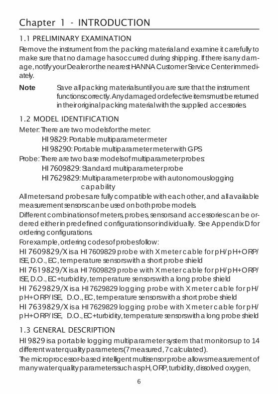
1.1 PRELIMINARY EXAMINATION
Remove the instrument from the packing material and examine it carefully tomake sure that no damage has occurred during shipping. If there is any dam-age, notify your Dealer or the nearest HANNA Customer Service Center immedi-ately.Note Save all packing materials until you are sure that the instrument
functions correctly. Any damaged or defective items must be returnedin their original packing material with the supplied accessories.
1.2 MODEL IDENTIFICATION
Meter: There are two models for the meter:HI 9829: Portable multiparameter meterHI 98290: Portable multiparameter meter with GPS
Probe: There are two base models of multiparameter probes:HI 7609829: Standard multiparameter probeHI 7629829: Multiparameter probe with autonomous logging
capabilityAll meters and probes are fully compatible with each other, and all availablemeasurement sensors can be used on both probe models.Different combinations of meters, probes, sensors and accessories can be or-dered either in predefined configurations or individually. See Appendix D forordering configurations.For example, ordering codes of probes follow:HI 7609829/X is a HI 7609829 probe with X meter cable for pH/pH+ORP/ISE, D.O., EC, temperature sensors with a short probe shieldHI 7619829/X is a HI 7609829 probe with X meter cable for pH/pH+ORP/ISE, D.O., EC+turbidity, temperature sensors with a long probe shieldHI 7629829/X is a HI 7629829 logging probe with X meter cable for pH/pH+ORP/ISE, D.O., EC, temperature sensors with a short probe shieldHI 7639829/X is a HI 7629829 logging probe with X meter cable for pH/pH+ORP/ISE, D.O., EC+turbidity, temperature sensors with a long probe shield
1.3 GENERAL DESCRIPTION
HI 9829 is a portable logging multiparameter system that monitors up to 14different water quality parameters (7 measured, 7 calculated).The microprocessor-based intelligent multisensor probe allows measurement ofmany water quality parameters such as pH, ORP, turbidity, dissolved oxygen,

7
GOOGLE™ is a registered trademark of Google, Inc. HANNA instruments® has no affiliation with Google™, Inc.iButton® is a registered trademark of Maxim/Dallas Semiconductor Corp.
conductivity, chloride, nitrate, ammonium and temperature with data logging.The system is easy to setup and easy to use.The HI 98290 with GPS option has a built-in 12 channel GPS receiver andantenna that guarantees a position accuracy of 10 m (30 ft).Measurements from specific locations are tracked with detailed coordinateinformation that can be viewed immediately on the display.GPS information can be transferred to a PC using HANNA’s HI 929829software. GPS information can also be viewed using a GPS mapping softwaresuch as Google™ Maps. Clicking on visited locations using a mapping softwaredisplays the measurement information.All HI 9829 are equipped with Fast Tracker™ an invaluable tool for associatingmeasurements with their locations. HANNA’s exclusive Fast Tracker™—T.I.S. (TagID System) uses iButton®s that can be installed at any number of sampling sites.The HI 9829 features a graphic, backlit display that automatically sizes thedigits to fit the screen with on-screen graphing capability. Each parameter is fullyconfigurable.HI 9829 was designed to withstand harsh environments and is the ideal solu-tion for field measurements of lakes, rivers and sea.The meter meets IP67 standards (30 minute immersion at a depth of 1 m) andthe multisensor probe meets IP68 standards (continuous immersion in water).Settings and logged data can be protected with a passcode to avoid unautho-rized modifications and context-sensitive help is always available.Main features of the HI 9829 system:• Rugged meter and probe• Easy to use• Measure up to 16 parameters and display of up to 12 parameters• Tracking of measurement locations with GPS (optional)• Waterproof protection (IP67 for the meter and IP68 for the probe)• Exclusive Fast Tracker™—T.I.S. (Tag ID System)• Graphic LCD with backlight• Built-in barometer for D.O. concentration compensation• Quick calibration feature• Measurement check to eliminate any erroneous readings• Autorecognition of probe and sensors• Log-on-demand and automatic logging (up to 45,000 samples) on meter for
all parameters• Graphical display of logged data

8
• USB interface for PC communication• Auto-ranging for EC, ISE and turbidity readings• Good Laboratory Practice feature, the last 5 calibrations are automatically
stored• Field-replaceable sensors with color coded caps• Meter can be powered with either alkaline or rechargeable batteries• Fast charging capability
1.4 DISPLAY & KEYBOARD DESCRIPTION
1. Graphic LCD2. Battery level indicator3. Softkey functions4. Left softkey: function defined on display5. On/Off key: turn the meter on and off6. Lamp key: turn the backlight on and off7. Alphanumeric keyboard: insert alphanumeric codes8. HELP key: obtain information about the displayed screen9. Arrow keys: scroll the displayed options/message
10. ESC key: return to the previous screen11. Right softkey: function defined on display12. GPS signal strength indicator (optional)13. Tag reader
9
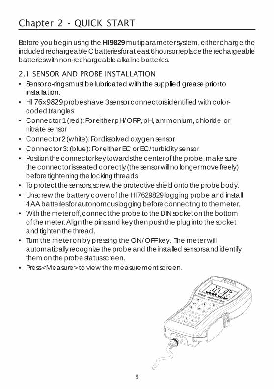
Chapter 2 - QUICK START
Before you begin using the HI 9829 multiparameter system, either charge theincluded rechargeable C batteries for at least 6 hours or replace the rechargeablebatteries with non-rechargeable alkaline batteries.
2.1 SENSOR AND PROBE INSTALLATION• Sensor o-rings must be lubricated with the supplied grease prior to
installation.• HI 76x9829 probes have 3 sensor connectors identified with color-
coded triangles:• Connector 1 (red): For either pH/ORP, pH, ammonium, chloride or
nitrate sensor• Connector 2 (white): For dissolved oxygen sensor• Connector 3: (blue): For either EC or EC/turbidity sensor• Position the connector key towards the center of the probe, make sure
the connector is seated correctly (the sensor will no longer move freely)before tightening the locking threads.
• To protect the sensors, screw the protective shield onto the probe body.• Unscrew the battery cover of the HI 7629829 logging probe and install
4 AA batteries for autonomous logging before connecting to the meter.• With the meter off, connect the probe to the DIN socket on the bottom
of the meter. Align the pins and key then push the plug into the socketand tighten the thread.
• Turn the meter on by pressing the ON/OFF key. The meter willautomatically recognize the probe and the installed sensors and identifythem on the probe status screen.
• Press <Measure> to view the measurement screen.

10
2.2 BASIC OPERATION
The main operating modes for HI 9829 are measurement, logging and setup.The measurement screen can be configured to display a single measurement orup to 12 simultaneous measurements by using the numbers 1-7 on the keypad.Use the arrow keys to scroll through the measurements not being displayed.See section 5.3 for more details.The measurement units will blink if the system has not been calibrated and themeasurement number will blink when the reading is out of range.

11
Press <Log> to display the logging menu. You can either log a single sampleon the meter, start an interval log on the meter, or start an interval log on alogging probe (HI 7629829). See chapter 11 for more details.Press <Menu> to enter setup mode. You can configure which parameters youwant to measure, calibrate the sensors, change system settings, access the GPSmenu and view the meter and probe status.
2.3 HELP FUNCTION
HI 9829 features context sensitive HELP, which provides useful information re-garding the displayed screen.Simply press the HELP key to access this function, then use the arrow keys toscroll through the message.To escape from the HELP window, press the HELP key again or ESC.
12
Chapter 3 - SPECIFICATIONS
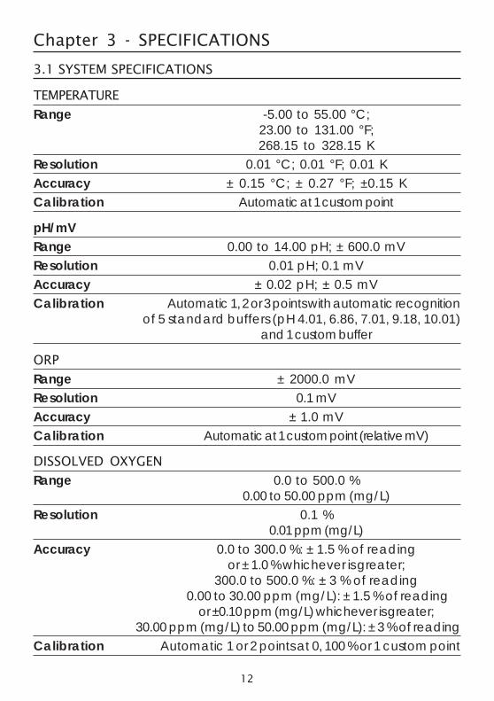
3.1 SYSTEM SPECIFICATIONS
TEMPERATURE
Range -5.00 to 55.00 °C;23.00 to 131.00 °F;268.15 to 328.15 K
Resolution 0.01 °C; 0.01 °F; 0.01 KAccuracy ± 0.15 °C; ± 0.27 °F; ±0.15 KCalibration Automatic at 1 custom point
pH/mVRange 0.00 to 14.00 pH; ± 600.0 mVResolution 0.01 pH; 0.1 mVAccuracy ± 0.02 pH; ± 0.5 mVCalibration Automatic 1, 2 or 3 points with automatic recognition
of 5 standard buffers (pH 4.01, 6.86, 7.01, 9.18, 10.01)and 1 custom buffer
ORP
Range ± 2000.0 mVResolution 0.1 mVAccuracy ± 1.0 mVCalibration Automatic at 1 custom point (relative mV)
DISSOLVED OXYGEN
Range 0.0 to 500.0 %0.00 to 50.00 ppm (mg/L)
Resolution 0.1 %0.01 ppm (mg/L)
Accuracy 0.0 to 300.0 %: ± 1.5 % of readingor ± 1.0 % whichever is greater;
300.0 to 500.0 %: ± 3 % of reading 0.00 to 30.00 ppm (mg/L): ± 1.5 % of reading
or ±0.10 ppm (mg/L) whichever is greater;30.00 ppm (mg/L) to 50.00 ppm (mg/L): ± 3 % of reading
Calibration Automatic 1 or 2 points at 0, 100 % or 1 custom point

13
CONDUCTIVITY
Range 0 to 200 mS/cm(absolute EC up to 400 mS/cm)
ResolutionManual 1 µS/cm; 0.001 mS/cm; 0.01 mS/cm; 0.1 mS/cm; 1 mS/cmAutomatic 1 µS/cm from 0 to 9999 µS/cm
0.01 mS/cm from 10.00 to 99.99 mS/cm0.1 mS/cm from 100.0 to 400.0 mS/cm
Automatic (mS/cm) 0.001 mS/cm from 0.000 to 9.999 mS/cm0.01 mS/cm from 10.00 to 99.99 mS/cm0.1 mS/cm from 100.0 to 400.0 mS/cm
Accuracy ±1 % of reading or ±1 µS/cm whichever is greaterCalibration Automatic single point, with 6 standard solutions
(84 µS/cm, 1413 µS/cm, 5.00 mS/cm, 12.88 mS/cm,80.0 mS/cm, 111.8 mS/cm) or custom point
RESISTIVITY
Range 0 to 999999 Ω·cm;(depending on measurement setup) 0 to 1000.0 kΩ·cm;
0 to 1.0000 MΩ·cmResolution Depending on resistivity readingCalibration Based on conductivity or salinity calibration
TDS (Total Dissolved Solids)
Range 0 to 400000 ppm (mg/L);(the maximum value depends on the TDS factor)
ResolutionManual 1 ppm (mg/L); 0.001 ppt (g/L);
0.01 ppt (g/L); 0.1 ppt (g/L); 1 ppt (g/L)Automatic 1 ppm (mg/L) from 0 to 9999 ppm (mg/L)
0.01 ppt (g/L) from 10.00 to 99.99 ppt (g/L)0.1 ppt (g/L) from 100.0 to 400.0 ppt (g/L)
Automatic ppt (g/L) 0.001 ppt (g/L) from 0.000 to 9.999 ppt (g/L)0.01 ppt (g/L) from 10.00 to 99.99 ppt (g/L)0.1 ppt (g/L) from 100.0 to 400.0 ppt (g/L)
Accuracy ±1 % of reading or ±1 ppm (mg/L) whichever is greaterCalibration Based on conductivity or salinity calibration

14
SALINITYRange 0.00 to 70.00 PSUResolution 0.01 PSUAccuracy ±2% of reading or ±0.01 PSU whichever is greaterCalibration Based on conductivity calibration
SEAWATER SIGMARange 0.0 to 50.0 σt, σ0, σ15
Resolution 0.1 σt, σ0, σ15
Accuracy ± 1σt, σ0, σ15
Calibration Based on conductivity or salinity calibration
TURBIDITYRange 0.0 to 99.9 FNU;
100 to 1000 FNUResolution 0.1 FNU from 0.0 to 99.9 FNU
1 FNU from 100 to 1000 FNUAccuracy ±0.3 FNU or ±2 % of reading,
whichever is greaterCalibration Automatic 1, 2 or 3 points at 0, 20 and 200 FNU, or custom
ISEAmmonium-NitrogenRange 0.02 to 200.0 ppm Am (as NH4
+-N)Resolution 0.01 ppm to 1 ppm
0.1 ppm to 200.0 ppmAccuracy ±5 % of reading or 2 ppmCalibration 1 or 2 point, 10 ppm and 100 ppm
Chloride
Range 0.6 to 200.0 ppm Cl (as Cl-)Resolution 0.01 ppm to 1 ppm
0.1 ppm to 200.0 ppmAccuracy ±5 % of reading or 2 ppmCalibration 1 or 2 point, 10 ppm and 100 ppm
15
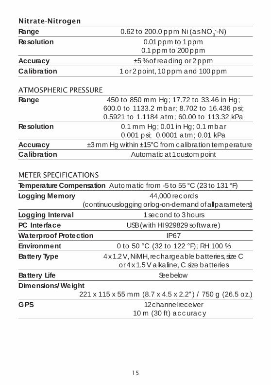
Nitrate-Nitrogen
Range 0.62 to 200.0 ppm Ni (as NO3--N)
Resolution 0.01 ppm to 1 ppm0.1 ppm to 200 ppm
Accuracy ±5 % of reading or 2 ppmCalibration 1 or 2 point, 10 ppm and 100 ppm
ATMOSPHERIC PRESSURERange 450 to 850 mm Hg; 17.72 to 33.46 in Hg;
600.0 to 1133.2 mbar; 8.702 to 16.436 psi;0.5921 to 1.1184 atm; 60.00 to 113.32 kPa
Resolution 0.1 mm Hg; 0.01 in Hg; 0.1 mbar0.001 psi; 0.0001 atm; 0.01 kPa
Accuracy ±3 mm Hg within ±15°C from calibration temperatureCalibration Automatic at 1 custom point
METER SPECIFICATIONS
Temperature Compensation Automatic from -5 to 55 °C (23 to 131 °F)Logging Memory 44,000 records
(continuous logging or log-on-demand of all parameters)Logging Interval 1 second to 3 hoursPC Interface USB (with HI 929829 software)Waterproof Protection IP67Environment 0 to 50 °C (32 to 122 °F); RH 100 %Battery Type 4 x 1.2 V, NiMH, rechargeable batteries, size C
or 4 x 1.5 V alkaline, C size batteriesBattery Life See belowDimensions/Weight
221 x 115 x 55 mm (8.7 x 4.5 x 2.2”) / 750 g (26.5 oz.)GPS 12 channel receiver 10 m (30 ft) accuracy
16
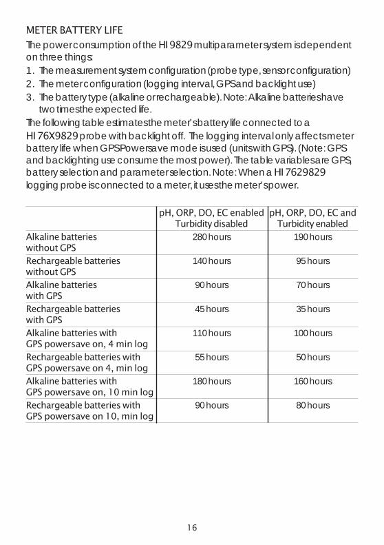
METER BATTERY LIFE
The power consumption of the HI 9829 multiparameter system is dependenton three things:1. The measurement system configuration (probe type, sensor configuration)2. The meter configuration (logging interval, GPS and backlight use)3. The battery type (alkaline or rechargeable). Note: Alkaline batteries have
two times the expected life.The following table estimates the meter’s battery life connected to aHI 76X9829 probe with backlight off. The logging interval only affects meterbattery life when GPS Powersave mode is used (units with GPS). (Note: GPSand backlighting use consume the most power). The table variables are GPS,battery selection and parameter selection. Note: When a HI 7629829logging probe is connected to a meter, it uses the meter’s power.
pH, ORP, DO, EC enabled pH, ORP, DO, EC andTurbidity disabled Turbidity enabled
Alkaline batteries 280 hours 190 hourswithout GPSRechargeable batteries 140 hours 95 hourswithout GPSAlkaline batteries 90 hours 70 hourswith GPS
Rechargeable batteries 45 hours 35 hourswith GPSAlkaline batteries with 110 hours 100 hoursGPS powersave on, 4 min log
Rechargeable batteries with 55 hours 50 hoursGPS powersave on 4, min logAlkaline batteries with 180 hours 160 hoursGPS powersave on, 10 min log
Rechargeable batteries with 90 hours 80 hoursGPS powersave on 10, min log

17
3.2 PROBE SPECIFICATIONS
Non-logging Probe Logging Probe
Sample Environment Fresh, brackish, seawater
Waterproof protection IP68
Computer Interface NA USB PC (HI 76982910)
Internal Battery Type NA 4 X 1.5V Size AA Alkaline
Typical Battery Life NA See below
Memory NA 140,000 measurements(single parameter logged)
35,000 measurements(all parameters logged)
Operating Temperature -5 to 55° C *
Storage Temperature -20 to 70° C
Maximum Depth 20 m (66 ft.) *
Dimensions HI 7609829 342mm (13.5”), HI 7629829 442mm (17.4"),(without cable) dia=46 mm (1.8”) dia=46 mm (1.8")
HI 7619829 382 mm (15.1”), HI 7639829 482 mm (19.0"),dia=46 mm (1.8”) dia=46 mm (1.8")
Weight HI 7609829 570g (20.1 oz.) HI 7629829 775g (27.3 oz.)(with batteries and sensors) HI 7619829 650g (22.9 oz.) HI 7639829 819g (28.9oz.)
Cable Specification Multistrand-multiconductor shielded cable with internal strength member rated for 68 kg (150 lb) intermittent use
Wetted Materials Body: ABSThreads: NylonShield: ABS/ 316 SSTemp probe: 316 SSO-rings: EPDM
* Reduced for ISE sensors
LOGGING PROBE BATTERY LIFE
Interval All channels logging All channels logging(no averaging) (10 sample averaging)
1 - 5 sec 72 hours 72 hours
1 min 22 days 11 days
10 min 70 days 65 days
18
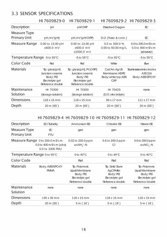
3.3 SENSOR SPECIFICATIONS
HI 7609829-0 HI 7609829-1 HI 7609829-2 HI 7609829-3
Description pH pH/ORP Dissolved Oxygen EC
Measure TypePrimary Unit pH, mV (pH) pH, mV (pH/ORP) D.O. (% sat. & conc.) EC
Measure Range 0.00 to 13.00 pH 0.00 to 13.00 pH 0.0 to 500.0 % 0.0 to 200.0 mS/cm±600.0 mV ±600.0 mV 0.00 to 50.00 mg/L 0.0 to 400 mS/cm
±2000.0 mV (absolute)
Temperature Range -5 to 55°C -5 to 55°C -5 to 55°C -5 to 55°C
Color Code Red Red White Blue
Materials Tip: glass (pH) Tip: glass (pH); Pt (ORP) Cat/An: Ag/Zn Stainless steel electrodesJunction: ceramic Junction: ceramic Membrane: HDPE AISI 316
Body: PEI Body: PEI Body: white top ABS Body: ABS/EPOXYElectrolyte: gel Electrolyte: gel CAP
Reference: double Reference: double
Maintenance HI 70300 HI 70300 HI 7042S noneSolution (storage solution) (storage solution) (D.O. electrolyte)
Dimensions 118 x 15 mm 118 x 15 mm 99 x 17 mm 111 x 17 mm
Depth 20 m (65’) 20 m (65’) 20 m (65’) 20 m (65’)
HI 7609829-4 HI 7609829-10 HI 7609829-11 HI 7609829-12
Description EC/Turbidity Ammonium ISE Chloride ISE Nitrate ISE
Measure Type EC ppm ppm ppmPrimary Unit FTU
Measure Range 0 to 200.0 mS/cm 0.02 to 200.0 ppm 0.6 to 200.0 ppm 0.6 to 200.0 ppm0.0 to 400 mS/cm (abs) as NH4
+-N Cl- as NO3--N
0.0 to 1000 FNU
Temperature Range-5 to 55°C 0 to 40°C 0 to 40°C 0 to 40°C
Color Code Red Red Red
Materials Body: ABS/EPOXY Tip: Polymeric Tip: Solid State Tip: PolymericPMMA Liquid Membrane AgCl Pellet Liquid Membrane
Body: PEI Body: PEI Body: PEIElectrolyte: gel Electrolyte: gel Electrolyte: gel
Reference: double Reference: double Reference: double
Maintenance none none none noneSolution
Dimensions 135 x 35 mm 118 x 15 mm 118 x 15 mm 118 x 15 mm
Depth 20 m (65’) 5 m ( 16‘) 5 m ( 16‘) 5 m ( 16‘)

19
Chapter 4 - PROBE INSTALLATIONHI 7609829 and HI 7629829 multisensor probes are used for the m e a -surements of pH, ORP, conductivity, turbidity, dissolved oxygen, chloride, nitrate-nitrogen, ammonium-nitrogen and temperature. Each probe can utilize 3 sen-sors. A description of each sensor follows.
4.1 SENSOR DESCRIPTIONS
HI 7609829-0 Combination pH sensor features a glasspH sensitive bulb and a silver/silver chloride double junc-tion reference with gelled electrolyte.HI 7609829-1 Combination pH/ORP sensor features aglass sensitive bulb for pH readings, a platinum sensor forredox measurements and a silver/silver chloride double junc-tion reference with gelled electrolyte.Note See section 4.2.1 for pH preparation.
See section 4.2.2 for ORP activation.
HI 7609829-2 Galvanic dissolved oxygen (D.O.)sensor. The thin gas permeable membrane isolates thesensor elements from the testing solution but allows oxygento pass through. The oxygen that passes through the mem-brane is reduced at the cathode and causes a current, fromwhich the oxygen concentration is determined. The D.O. sen-sor conforms to Standard Methods 4500-AG, EPA 360.1.
Note The D.O. sensor needs to be activated beforeinstallation. See section 4.2.3 for details.
HI 7609829-3 4-electrode conductivity sensor. The sensoris immune to polarization or surface coatings.
The HI 7609829-4 Combination EC/Turbidity sensor. Itincludes a 4-electrode conductivity sensor and a turbiditysensor that conforms to ISO 7027 standards in a singlesensor body. The turbidity sensor uses an optical techniqueto measure suspended particles in water.

20
HI 7609829-10: Ammonium selective electrode (ISE) is acombination liquid membrane sensor used for the detec-tion of free ammonium-nitrogen in freshwater samples. Thesensor utilizes a polymeric membrane made with ammo-nium ionophore in a PVC head and silver/silver chloridedouble junction gel filled reference electrode. This sensor isused in place of the pH sensor in the probe.
HI 7609829-11: The Chloride ISE is a combination solid state sensor used forthe detection of free chloride ions in freshwater samples. The sensor utilizes asilver chloride pellet housed in a PEI head and a silver/silver chloride doublejunction gel filled reference electrode. This sensor is used in place of the pHsensor in the probe.
HI 7609829-12: The Nitrate ISE is a combination liquid membrane sensorused for the detection of nitrate nitrogen in freshwater samples. The sensor uti-lizes a polymeric membrane made with nitrate ionophore in a PVC head and asilver/silver chloride double junction gel filled reference electrode. This sensor isused in place of the pH sensor in the probe.
See Appendix C for details regarding the ISE sensors.
21
4.2 SENSOR PREPARATION / ACTIVATION
4.2.1 pH Preparation
Remove the shipping cap from the pH sensor. If the shipping cap does notcontain any liquid, pour HI 70300 into shipping cap, place it back on thesensor and soak for at least 1/2 hour before use. If HI 70300 is not available,pH 4.01 buffer may be substituted.
4.2.2 ORP Activation
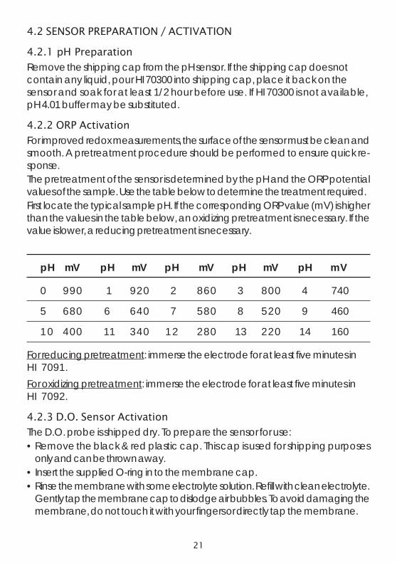
For improved redox measurements, the surface of the sensor must be clean andsmooth. A pretreatment procedure should be performed to ensure quick re-sponse.The pretreatment of the sensor is determined by the pH and the ORP potentialvalues of the sample. Use the table below to determine the treatment required.First locate the typical sample pH. If the corresponding ORP value (mV) is higherthan the values in the table below, an oxidizing pretreatment is necessary. If thevalue is lower, a reducing pretreatment is necessary.
pH mV pH mV pH mV pH mV pH mV
0 990 1 920 2 860 3 800 4 740
5 680 6 640 7 580 8 520 9 460
10 400 11 340 12 280 13 220 14 160
For reducing pretreatment: immerse the electrode for at least five minutes inHI 7091.For oxidizing pretreatment: immerse the electrode for at least five minutes inHI 7092.
4.2.3 D.O. Sensor Activation
The D.O. probe is shipped dry. To prepare the sensor for use:• Remove the black & red plastic cap. This cap is used for shipping purposes
only and can be thrown away.• Insert the supplied O-ring in to the membrane cap.• Rinse the membrane with some electrolyte solution. Refill with clean electrolyte.
Gently tap the membrane cap to dislodge air bubbles. To avoid damaging themembrane, do not touch it with your fingers or directly tap the membrane.
22
• With the sensor facing down screw the membrane cap counterclockwise to theend of the threads. Some electrolyte will overflow.
• Rinse outside of sensor with deionized water.• Invert sensor and inspect. There should be no bubbles or debris between the
membrane and sensor body.
4.2.4 EC and EC/Turbidity Sensor Preparation
The EC and EC/Turbidity sensors do not need to be soaked or hydrated beforeuse. Use the small brush included in the probe maintenance kit to clean andloosen any debris before using.
4.2.5 Ammonium Sensor Preparation
Remove the shipping cap and inspect sensor. Verify no air pockets have devel-oped near the ceramic junction during shipping. Hold the sensor at the connec-tor and shake it down (like a mercury thermometer). Condition the sensor bysoaking it in a small amount of HI 9829-10, 10 ppm NH4
+-N standard for atleast a 1/2 hour.
4.2.6 Chloride Sensor Preparation
Remove the shipping cap and inspect sensor. Verify no air pockets have devel-oped near the ceramic junction during shipping. Hold the sensor at the connec-tor and shake it down (like a mercury thermometer). Condition the sensor bysoaking it in a small amount of HI 9829-12, 10 ppm Cl- standard for at leasta 1/2 hour.
4.2.7 Nitrate Sensor Preparation
Remove the shipping cap and inspect sensor. Verify no air pockets have devel-oped near the ceramic junction during shipping. Hold the sensor at the connec-tor and shake it down (like a mercury thermometer). Condition the sensor bysoaking it in a small amount of HI 9829-14, 10 ppm NO3
--N standard for atleast a 1/2 hour.

23
4.3 SENSOR INSTALLATION
The HI 76x9829 can support 3 different sensors: Connector 1: pH, pH/ORP orISE (Ammonium, Chloride, Nitrate), Connector 2: D.O., Connector 3: EC orEC/Turbidity.To make installation easier, the sensors have color-coded caps and the socketsare identified with colored triangles.
Note The EC/Turbidity sensor with 9 pin connector does not have acolor-coded cap. It is always installed into the socket with three bluetriangles.

24
For a correct installation:• Grease the sensor O-ring with the lubricant found in the probe maintenance
kit. DO NOT SUBSTITUTE other grease/lubricants as it may cause the O-ringto swell.
• Insert the sensor into the correctly color coded opening while positioning theconnector key toward the center of the probe. Make sure the connector isseated correctly (the sensor will no longer move freely) before tightening thelocking threads with your fingers.
• Continue to tighten the locking threads with the tool supplied in the maintenance kit until the sensor is secured tightly against the probe body.
• To protect the sensors, screw the protective shield onto the probe body.• With the meter off, connect the probe to the DIN socket on the bottom of the
meter. Align the pins and key then push the plug into the socket. Tighten theknurled, threaded shell.
• Turn on the meter by pressing the ON/OFF key. The metershould automatically recognize the installed sensors andidentify them on the probe status screen. If you have anerror message or the sensor is not recognized, reconnectthe sensor(s) or probe and try again.

25
Chapter 5 - INITIALIZATION AND MEASUREMENT
5.1 BATTERY INSTALLATION
HI 9829 is supplied with 4 rechargeable, size C NiMH (Nickel-metal hydride)batteries.The battery symbol on the LCD indicates the remaining battery charge. The meterhas a low battery warning, and when the symbol starts blinking, batteries shouldbe charged or replaced with new ones. When the batteries are discharged themeter will automatically shut off to avoid erroneous readings.
5.1.1 Meter Battery Installation
Replace batteries in nonhazardous areas only.Remove the 4 screws on the rear of the instru-ment and insert the batteries observing polar-ity.If you wish to replace the supplied recharge-able batteries with nonrechargeble alkaline bat-teries, move the switch in the battery compart-ment upward.A warning message is displayed if youconnect the charging cable to a meter withalkaline batteries.
Nonrechargeable alkaline batteries can explode or leak if youtry to charge them. Verify that the switch is in the up positionwhen using alkaline batteries to prevent recharging.
Note: Do not mix old and new alkaline batteries.
5.1.2 Charging Meter Batteries
Two cables are available for charging the HI 9829 batteries: HI 710045 andHI 710046.AC power supplyIn order to charge the rechargeable batteries, use the HI 710045 cable and the12 Vdc power adapter.• With the meter OFF, disconnect the probe.• Connect the HI 710045 cable to the probe connector on the meter and
power adapter, then connect the adapter to an AC power outlet.• The battery charging animation will be displayed.

26
It takes about 6 hours to completely charge fullydischarged batteries.
Note The meter log, GPS information, system setup and status can be viewedduring battery charging. The battery charging status is indicated by asmall animated battery icon found in the lower left corner.During charging the meter may feel quite warm. This is normal.“Battery temp” (under “Meter Status”) may display values approaching50 °C.
Automotive auxiliary power outlet (Cigarette lighter receptacle)To charge batteries from a automotive auxiliary power outlet, use HI 710046cable.• Connect the HI 710046 cable to the probe connector on the meter and to
the auxiliary plug.• The battery charging animation will be displayed.
A complete battery charging will take about 6 hours if they are completelydischarged.
5.1.3 Probe Battery Installation (for logging probesonly)
To install probe batteries:Replace batteries in a nonhazardous areaonly. Remove the battery cover by turning itcounterclockwise. Insert the batteriesobserving polarity.
Note: Do not mix old and newbatteries.
Replace the battery cover by engaging thethreads and turning it clockwise. Continueturning until it is flush with probe body.

27
5.2 METER INITIALIZATION
After connecting the desired sensors to the probe and connecting the probe tothe meter (see previous chapter), turn the meter on by pressing ON/OFF.After the initialization has been completed, the meter displays the PROBE STA-TUS SCREEN.
The probe status screen identifies the probe and attached sensors. Non-loggingprobes are identified as HI 7609829 and logging probes are identified asHI 7629829.
Two active soft keys are found at the bottom of the status screen.• Press <Measure> to access the measurement mode.• Press <Param> to access the “Select Parameter” menu. (This screen can also
be accessed from the main menu, see Chapter 6 for a detailed description.).• Press the DOWN arrow to view additional information about the probe.
28
5.3 MEASUREMENT MODE
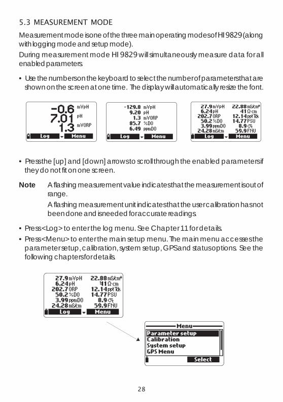
Measurement mode is one of the three main operating modes of HI 9829 (alongwith logging mode and setup mode).During measurement mode HI 9829 will simultaneously measure data for allenabled parameters.
• Use the numbers on the keyboard to select the number of parameters that areshown on the screen at one time. The display will automatically resize the font.
• Press the [up] and [down] arrows to scroll through the enabled parameters ifthey do not fit on one screen.
Note A flashing measurement value indicates that the measurement is out ofrange.A flashing measurement unit indicates that the user calibration has notbeen done and is needed for accurate readings.
• Press <Log> to enter the log menu. See Chapter 11 for details.• Press <Menu> to enter the main setup menu. The main menu accesses the
parameter setup, calibration, system setup, GPS and status options. See thefollowing chapters for details.

29
5.4 SETUP MENU STRUCTURE
30
Chapter 6 - PARAMETER SETUP MENU
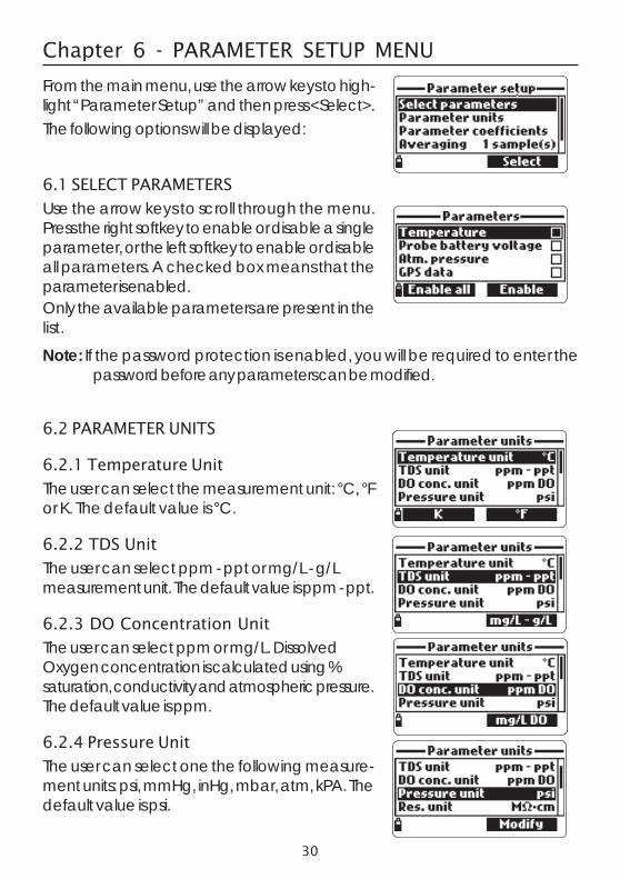
From the main menu, use the arrow keys to high-light “Parameter Setup” and then press <Select>.The following options will be displayed:
6.1 SELECT PARAMETERS
Use the arrow keys to scroll through the menu.Press the right softkey to enable or disable a singleparameter, or the left softkey to enable or disableall parameters. A checked box means that theparameter is enabled.Only the available parameters are present in thelist.
Note: If the password protection is enabled, you will be required to enter thepassword before any parameters can be modified.
6.2 PARAMETER UNITS
6.2.1 Temperature Unit
The user can select the measurement unit: °C, °For K. The default value is °C.
6.2.2 TDS Unit
The user can select ppm - ppt or mg/L - g/Lmeasurement unit. The default value is ppm - ppt.
6.2.3 DO Concentration Unit
The user can select ppm or mg/L. DissolvedOxygen concentration is calculated using %saturation, conductivity and atmospheric pressure.The default value is ppm.
6.2.4 Pressure Unit
The user can select one the following measure-ment units: psi, mmHg, inHg, mbar, atm, kPA. Thedefault value is psi.

31
6.2.5 Resistivity UnitThe user can select resistivity from one of the fol-lowing measurement units: Ω·cm, kΩ·cm orMΩ·cm. Resistivity is calculated from the conduc-tivity measurement. The default unit is MΩ·cm.6.2.6 Seawater Sigma UnitThis parameter is used for seawater analysis. It iscalculated from the conductivity measurement anddepends on water pressure, temperature and sa-linity. The default value is σt.Users can select the reference temperature: σt, σ0and σ15 (i.e. current temperature, 0°C or 15°C).6.2.7 Distance Unit (GPS unit)Select between m - km or ft - mi. This unit will beassociated with position. The default values is m -km.6.2.8 EC ResolutionThe user can configure the conductivity resolu-tion with one of the following options:Auto: the meter automatically chooses the rangeto optimize the measurement. Readings can be inµS/cm or mS/cm.Auto mS/cm: the meter automatically chooses therange to optimize the measurement, readings will be in mS/cm only.1µS/cm, 0.001 mS/cm, 0.01mS/cm, 0.1mS/cm or 1mS/cm: the meter will notautorange, the measurement will be displayed with the selected resolution. Thedefault value is Auto.6.2.9 Absolute EC ResolutionAbsolute conductivity displays the conductivity without temperature compensa-tion. See 6.2.8 EC resolution for resolution details.Note A small letter “A” added to the µS/cm or mS/cm unit refers to an abso-
lute conductivity value (i.e. a conductivity reading with no temperaturecompensation).
6.2.10 TDS ResolutionThe user can configure the TDS resolution with one of the following options:Auto: the meter automatically chooses the range to optimize the measurement,readings can be in ppt or ppm.

32
Auto ppt: the meter automatically chooses the range to optimize the measure-ment, readings will be in ppt only.1 ppm, 0.001 ppt, 0.01 ppt, 0.1 ppt or 1 ppt: the meter will display the mea-surement with selected resolution. The default value is Auto.6.2.11 GPS Format (optional)
Global positioning coordinates have threestandard formats: XX°XX’XX.X’’, XX°XX.XXX’ andXX.XXXXX°. The selected format will be used in anyscreen where the GPS coordinates are displayed.The default format is XX°XX’XX.X.
6.3 PARAMETER COEFFICIENTS
6.3.1 EC Reference Temperature
This value is used for temperature compensatedconductivity. All EC measurements will be refer-enced to the conductivity of a sample at this tem-perature. Press the softkey to select the desiredoption; 20 °C or at 25 °C. The default value is25 °C.
6.3.2 EC Temperature Coefficient
The temperature coefficient Beta (β) is defined bythe following equation (using 25 °C as an ex-ample): EC25=ECx/(1+β(Tx-25))Beta is a function of the solution being measured.For freshwater samples Beta is approximately1.90%/°C. If the actual temperature coefficient of your sample is known, press<Modify> to enter the value. To confirm press <Accept>. The value can bewithin 0.00 and 6.00%/°C. The default value is 1.90%/°C.
6.3.3 TDS Factor
TDS stands for total dissolved solids, and it is acalculated value based on the conductivity of thesolution (TDS = factor x EC25). The TDS conver-sion factor can be set from 0.00 to 1.00. A typi-cal TDS factor for strong ionic solutions is 0.5,while for weak ionic solutions (e.g. fertilizers) is 0.7.Press <Modify> to enter the value, press <Ac-cept> to confirm. The default value is 0.50.
33
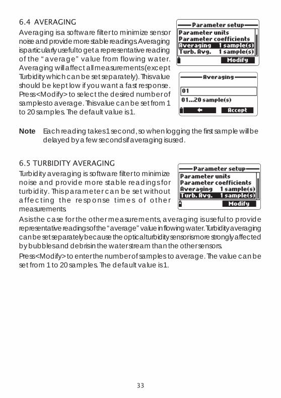
6.4 AVERAGINGAveraging is a software filter to minimize sensornoise and provide more stable readings. Averagingis particularly useful to get a representative readingof the “average” value from flowing water.Averaging will affect all measurements (exceptTurbidity which can be set separately). This valueshould be kept low if you want a fast response.Press <Modify> to select the desired number ofsamples to average. This value can be set from 1to 20 samples. The default value is 1.
Note Each reading takes 1 second, so when logging the first sample will bedelayed by a few seconds if averaging is used.
6.5 TURBIDITY AVERAGINGTurbidity averaging is software filter to minimizenoise and provide more stable readings forturbidity. This parameter can be set withoutaffecting the response times of othermeasurements.As is the case for the other measurements, averaging is useful to providerepresentative readings of the “average” value in flowing water. Turbidity averagingcan be set separately because the optical turbidity sensor is more strongly affectedby bubbles and debris in the water stream than the other sensors.Press <Modify> to enter the number of samples to average. The value can beset from 1 to 20 samples. The default value is 1.

34
Chapter 7 - CALIBRATION MODEHI 9829’s calibration routines are accessed by highlighting “Calibration” andpressing <Select> from the main menu. Calibration is the process that stan-dardizes the electrical or optical signals from the sensors to reagent standardsof known value.Calibrations are intuitive and menu driven. Allcalibration data is stored in the non volatile probememory, allowing probes to be connected todifferent meters without recalibration.There are two types of calibrations available: the“Quick calibration”, which is used for a singlepoint calibration of pH, Conductivity, and/orDissolved Oxygen and is handy for field work;and the “Single param. calibration” that allows each parameter to becalibrated individually. The user may also restore each parameter to a factorydefault calibration.Note The password will be required if password protection is enabled.To optimize measurements, it is advisable to establish the optimum calibrationperiod required for the measurement environment.Calibration requirements vary with deployment conditions, for example very turbidbiologically-active waters may require more frequent cleanings and calibrationsthan cleaner waters.General calibration guidelines are listed below:• Set up a routine service schedule where measurement integrity is validated.
This is especially important for new installation sites or long deployments.• Inspect sensor connectors for corrosion and replace damaged sensors.• Inspect sensor o-rings for damage and if necessary replace and lubricate
with the grease found in the probe maintenance kit.• Do not handle the sensing surfaces of the sensors.• Avoid rough handling and abrasive environments that can scratch the
reactive surfaces of the sensors.• Avoid long-term exposure of sensors to bright sunlight (especially chloride
ISE). If possible, calibrate in a shaded area.• Discard standards after use. Do not return the used standards to the bottles
of “fresh” solution.• For measurements across a temperature gradient (when water temperature
is drastically different from the standards), permit the sensors to reach thermalequilibrium before conducting calibrations or making measurements. Theheat capacity of the probe is much greater than the air and the small beakersof calibration standards.

35
7.1 QUICK CALIBRATION
The quick calibration method provides a quick single point calibration for pH,conductivity and dissolved oxygen sensors. HI 9828-25 calibration solution isused for both pH and conductivity.• Fill the calibration beaker 2/3 full with HI 9828-25 calibration solution.• Slowly place the sensors into the solution and
dislodge bubbles that may adhere to the sensors.• Screw the calibration beaker completely on the
probe body. Some solution may overflow.• Wait a few minutes for the system to stabilize.• From the “Calibration” menu select “Quick
calibration”.• A three item calibration menu will appear (pH,
Conductivity and Dissolved oxygen) and “pH”will start to blink along with the “Not ready”message.
• When the pH signal is stable, the “Ready”message appears. Press <Confirm> to store thecalibration data.
• The “Storing” message will appear as thecalibration proceeds to the next sensor. Acheckmark will appear in the box next to “pH” toindicate a successful calibration.
Note To bypass any of the calibrations press<Skip> to move to the next sensor in thequick calibration menu.If the pH sensor is not installed the message“pH sensor not installed! Skip toconductivity calibration” will appear.
• Following the pH calibration, “Conductivity” will start to blink along with the“Not ready” message.
• When the measurement is stable, “Ready” appears. Press <Confirm> to storethe calibration data and the “Storing” message will appear.
Note If EC calibration is not required, skip tothe D.O. quick calibration by pressing the<Skip> softkey.
• The message “Empty the beaker.” will appear.
36
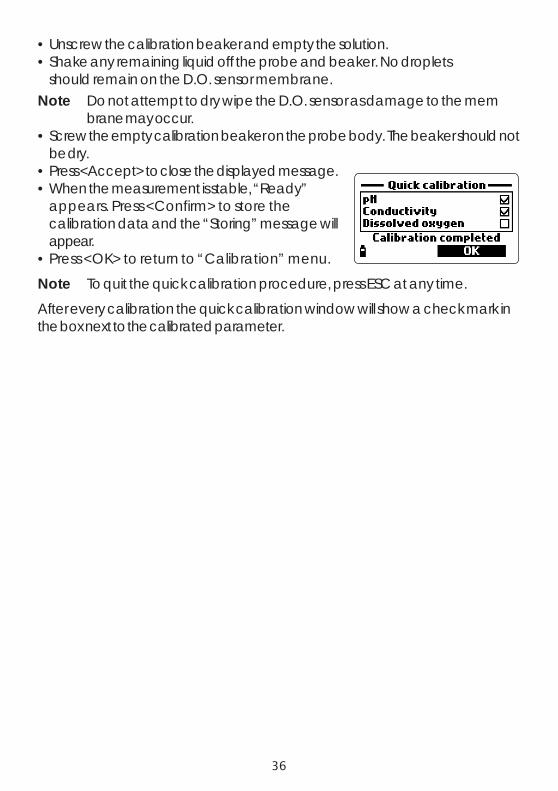
• Unscrew the calibration beaker and empty the solution.• Shake any remaining liquid off the probe and beaker. No droplets
should remain on the D.O. sensor membrane.Note Do not attempt to dry wipe the D.O. sensor as damage to the mem
brane may occur.• Screw the empty calibration beaker on the probe body. The beaker should not
be dry.• Press <Accept> to close the displayed message.• When the measurement is stable, “Ready”
appears. Press <Confirm> to store thecalibration data and the “Storing” message willappear.
• Press <OK> to return to “Calibration” menu.
Note To quit the quick calibration procedure, press ESC at any time.
After every calibration the quick calibration window will show a check mark inthe box next to the calibrated parameter.

37
7.2 pH CALIBRATION
To optimize the pH measurement follow the general guidelines mentioned in theChapter 7 introduction.From the “Calibration” menu select “Singleparam. calibration” and then “pH calibration”. Thedisplay shows two options: “Calibrate pH” and“Restore factory calib.”.If a new pH sensor has been installed use “Restorefactory calib.” before performing a user calibrationas some warning messages are based on changes from previous calibrations.If “Restore Factory Calib” is selected, all user calibration data will be deleted andthe default calibration is restored. A user calibration should follow immediately.If “Calibrate pH” is selected, the user can perform a new calibration using up to3 buffers (pH 4.01, 6.86, 7.01, 9.18, 10.01 or one custom buffer).When a 3-point calibration is performed, all old data are overwritten, while witha single or 2-point calibration the meter will also use information from the previouscalibration.
7.2.1 Preparation
Pour small quantities of the selected buffer solutions into clean beakers. Tominimize cross contamination, use two beakers for each buffer solution: thefirst one for rinsing the sensor and the second one for calibration.
7.2.2 Procedure
The measured pH value is displayed, along with the temperature and the buffervalue on the second level.If necessary, press the <Cal point> softkey and use the arrow keys to select thecorrect buffer.• Immerse the sensors in the first buffer rinse so-
lution and stir gently.• Immerse the pH sensor and temperature probe
into the selected buffer and stir gently. Thetemperature, pH buffer value and the “Notready” message are displayed.
• Once the reading has stabilized the countdowntimer will count down until the display showsthe “Ready” message.
• Press <Confirm> to accept the calibrationpoint.

38
• After the calibration point is confirmed, to avoid cross-contamination immersethe sensors in the next calibration buffer rinse solution and stir gently.
• Press <Cal Point> to select the next buffer (if necessary), and repeat the cali-bration procedure outlined above with the second and third buffers.
Note The calibration procedure can be terminated after a single or 2 pointcalibration by pressing <ESC>. The message “Storing” followed by“Calibration completed” will be displayed.
• Press <OK> to return to the Calibration menu.• Press <Measure> to return to the measurement screen.
Custom buffer calibrationThe HI 9829 permits a single custom buffer to beused for pH calibration. This can be used alongwith standard buffers as part of a 2 or 3 pointcalibration or as a single point.• To select this option first press <Cal. point> and
then <Custom> while the meter is waiting forstable reading.
• A text box window will appear. Use the keypad to enter the value of the bufferat the current temperature. The valid range for custom a buffer is from 0.00to 14.00 pH.

39
7.2.3 pH Calibration Error Messages
The HI 9829 displays a series of messages if an error has occurred duringcalibration.If the meter does not accept a pH calibration point, a short message is displayedto indicate the possible error source. The following screens are examples:
These are the available messages:• “Input out of scale”: the pH value is out of range. The pH sensor may
require replacement.• “Check sensor”: the electrode may be broken, very dirty or the user has
attempted to calibrate the same buffer value twice.• “Wrong buffer”: the displayed pH reading is too far from the selected buffer
value. This is often seen immediately after a buffer calibration has beencompleted but before the pH sensor has been moved to the next buffer. Checkif the correct calibration buffer has been selected.
• “Invalid temperature”: the buffer temperature is outside the acceptable range.• “Wrong buffer” / “Contaminated buffer” / “Check electrode”: the buffer is
contaminated or the sensor is broken or very dirty.• “Check sensor” / “Clean sensor”: the electrode is broken or very dirty.• “Wrong” / “Clear old calibration”: erroneous slope condition. These messages
appear if the slope difference between the current and previous calibrationexceeds the slope window (80% to 110%). Press the <Clear> softkey to cancelthe old data and continue the calibration procedure, or press ESC to quit thepH calibration mode.

40
7.3 ISE CALIBRATIONFrom the “Calibration” menu select “Singleparam. calibration” and then “ISE calibration”. Thedisplay shows two options: “Calibrate ISE” and“Restore factory calib”.When an ISE replaces a pH sensor or another ISEmodel, previous calibrations need to becleared using the <Restore factory calib.>option first.If “Calibrate ISE” is selected, the user can perform a single (10 ppm) or 2 pointcalibration with standard 10 ppm and 100 ppm solutions.If “Restore Factory Calib” is selected, all user calibration data will be deleted andthe default calibration is restored.Notes The ppm tag will blink when a user calibration was not performed.When a 2-point calibration is performed, all of the old data is overwritten, whereasfor a single point calibration the meter will also use information from the previouscalibration.7.3.1 PreparationPrepackaged standards are available in single use sachets. Rinse the ISE withwater and shake off excess water. The procedure always uses 10 ppm first.7.3.2 ProcedureCut open the 10 ppm sachet and pour a small quantity of standard over the ISEtip to rinse the sensor. This should be done over a waste container. Immerse theISE sensor and temperature probe into the standard. Position the sachet toensure sensor membrane and ceramic junction are completely covered withsolution.The current measurement or dashes,temperature, the standard value and the “Notready” message are displayed.• Once the ISE has stabilized the countdown
timer will count down until the display showsthe “Ready” message.
• Press <Confirm> to accept the calibrationpoint.
• After the first calibration point is confirmed,remove sensor from sachet packet and shakestandard off. Blot excess with a soft tissue. Cutopen the 100 ppm sachet. Immerse the ISEsensor and temperature probe into thestandard.
41
Position the sachet to ensure sensor membrane and ceramic junction arecompletely immersed in solution. A value close to 100 ppm and the message“Not ready...” will be displayed.
• When the reading is stable, the countdowntimer will count down until the display showsthe “Ready” message.
• Press <Confirm> to accept the calibration.• After the second calibration point is confirmed the display shows the
following messages: “Storing” and “Calibration completed”.• Press <OK> to return to the Calibration menu.• Press <Measure> to return to the measurement screen.
Note The ISE calibration mode can be exited at any time, by pressing theESC key.
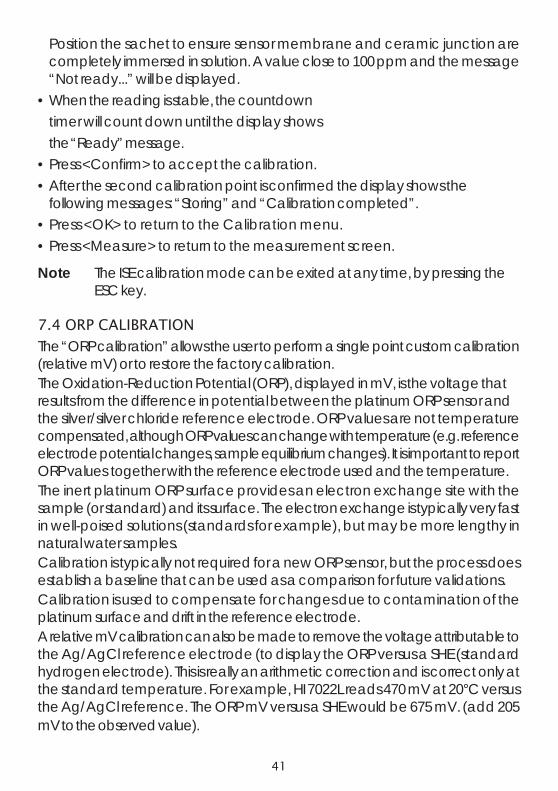
7.4 ORP CALIBRATION
The “ORP calibration” allows the user to perform a single point custom calibration(relative mV) or to restore the factory calibration.The Oxidation-Reduction Potential (ORP), displayed in mV, is the voltage thatresults from the difference in potential between the platinum ORP sensor andthe silver/silver chloride reference electrode. ORP values are not temperaturecompensated, although ORP values can change with temperature (e.g. referenceelectrode potential changes, sample equilibrium changes). It is important to reportORP values together with the reference electrode used and the temperature.The inert platinum ORP surface provides an electron exchange site with thesample (or standard) and its surface. The electron exchange is typically very fastin well-poised solutions (standards for example), but may be more lengthy innatural water samples.Calibration is typically not required for a new ORP sensor, but the process doesestablish a baseline that can be used as a comparison for future validations.Calibration is used to compensate for changes due to contamination of theplatinum surface and drift in the reference electrode.A relative mV calibration can also be made to remove the voltage attributable tothe Ag/AgCl reference electrode (to display the ORP versus a SHE (standardhydrogen electrode). This is really an arithmetic correction and is correct only atthe standard temperature. For example, HI 7022L reads 470 mV at 20°C versusthe Ag/AgCl reference. The ORP mV versus a SHE would be 675 mV. (add 205mV to the observed value).

42
7.4.1 PreparationAppendix D – ACCESSORIES lists Hanna solutions used for ORP calibrations.The calibration should be conducted at temperatures between 20-26°C. Thesensor should be clean and oil free.
7.4.2 Procedure• From the “Calibration” menu select “Single
param. calibration” and then “ORP calibration”.The display shows two options: “Custom ORP”and “Restore factory calib.”.
• For a user calibration select “Custom ORP”.• Fill a beaker with an ORP test solution (see
APPENDIX D “Accessories”).• Using the keypad, insert the numerical ORP
value and then press <Accept> to confirm.• The stability counter will count down and the
message “Ready” and <Confirm> will bedisplayed.
• Press <Confirm> to accept the calibrationpoint.
• After confirmation, the following messages are displayed: “Storing” and“Calibration completed”.
• Press OK to return to the Calibration menu.• Press <Measure> to return to the measurement screen.• To restore the factory calibration data, select the corresponding option in the
“ORP calibration” menu and then press <Select>.
7.5 DISSOLVED OXYGEN CALIBRATIONThe accuracy of dissolved oxygen measurements is directly related to membranecleanliness and calibration technique. Oily coating and biological contaminantsare the primary cause of calibration drift in dissolved oxygen sensors. Unfortu-nately, brushes or other cleaning objects may damage the membrane. Replac-ing the membrane cap and electrolyte is the best way to perform periodic main-tenance.Although it may be easier to calibrate the D.O. sensor prior to deployment, it isadvised to calibrate at the site of deployment. Errors in measurement may resultif altitude and barometric pressure differ between the calibration and measure-ment site. This is very important for autonomously logging probes.
Note Perform either the % D.O. Saturation or D.O. Concentration calibration.

43
If the % D.O. saturation range is calibrated, the D.O. concentration range willalso be calibrated, and vice versa.Dissolved oxygen concentration values are basedon % D.O. saturation, temperature, salinity andatmospheric pressure. A standard solution or areference D.O. meter may be used to comparereadings during calibration.The calibration of the D.O. concentration rangecan only be performed at a single custom point (4 to 50 mg/L). It is recommendedto calibrate the D.O. sensor close to the values that will be measured.
Choose “DO calibration” from the “Calibration” menu, select the D.O. calibrationtype using the arrow keys and press <Select> to confirm.
% D.O. saturationThe calibration of the % D.O. saturation rangecan be performed at a single or 2 standard points(0 % and 100 %), or at a single custom point (50% to 500 %).Procedure:• To calibrate at 100 %, fill the calibration beaker
with approximately 4 mm (5/32") of water andscrew it onto the probe. The membrane shouldnot be wet. This condition corresponds to air100 % saturated with oxygen and water vapor.
• The reading, temperature, calibration point andthe “Not ready” message are displayed.
• Once the reading has stabilized the countdowntimer will count down until the display showsthe “Ready” message.
• Press <Confirm> to accept the calibration point. After confirmation, put theD.O. and temperature sensors into HI 7040L zero oxygen solution and waitfor stability to be reached. The stability timer will count down and <Confirm>will appear. Press <Confirm> to store the calibration.
• The following messages will appear: “Storing” and “Calibration completed”.• Press <OK> to return to the “Calibration” menu.• Press ESC twice to return to the main menu.• Press <Measure> to return to the measurement screen.
Note The user can perform a single point calibration by pressing <ESC>after the first point is accepted.
44
Note If the D.O. input is not within the acceptable range, the message “Invalidinput” is displayed.
Single point Custom % saturation calibration• For a calibration at another known value place sensor and temperature probe
into the known solution and change the calibration value, press the<Cal. point> softkey and select the desired point.
• To insert a different calibration value, press <Cal. point> and then <Custom>.Insert the desired value using the keypad, then press <Accept>.
• When the reading is stable, the “Ready” message is displayed. Press<Confirm> to store the calibration point.
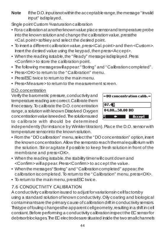
• The following messages will appear: “Storing” and “Calibration completed”.• Press <OK> to return to the “Calibration” menu.• Press ESC twice to return to the main menu.• Press <Measure> to return to the measurement screen.D.O. concentrationVerify the barometric pressure, conductivity andtemperature reading are correct. Calibrate themif necessary. To calibrate the D.O. concentrationrange, a solution with known Dissolved Oxygenconcentration value is needed. The solutions usedto calibrate with should be determinedindependently (for instance by Winkler titration). Place the D.O. sensor withtemperature sensor into the known solution.• From the “DO calibration” menu, select the “DO concentration” option, insert
the known concentration. Allow the sensors to reach thermal equilibrium withthe solution. Stir or agitate if possible to keep fresh solution in front of themembrane and press <OK>.
• When the reading is stable, the stability timer will count down and<Confirm> will appear. Press <Confirm> to accept the value.
• When the messages “Storing” and “Calibration completed” appear, thecalibration is completed. To return to the “Calibration” menu, press <OK>.
• To return to the main menu, press ESC twice.
7.6 CONDUCTIVITY CALIBRATIONA conductivity calibration is used to adjust for variations in cell factors byusing a standard solution of known conductivity. Oily coating and biologicalcontaminants are the primary cause of calibration drift in conductivity sensors.This type of fouling changes the apparent cell geometry, resulting in a shift in cellconstant. Before performing a conductivity calibration inspect the EC sensor fordebris or blockages. The EC electrodes are situated inside the two small channels

45
found in the bottom of the conductivity sensor. Clean using the small brush fromthe probe maintenance kit. Flush with water. A mild detergent may be used toremove oily coatings. Always flush with clean water after cleaning.
Note For a correct conductivity calibration, the probe shield or the calibrationbeaker must be used.
The conductivity calibration menu includes 3different types of calibration: Conductivity, Absoluteconductivity and Salinity.The “Conductivity” option allows a single pointcalibration with a standard solution selectable bythe user. This calibration is temperaturecompensated.The “Absolute conductivity” option allows a single point calibration with aconductivity solution of known non-temperature compensated value at the currenttemperature.The “Salinity” option allows calibration with a standard salinity solution.The 3 calibrations are related, so that each one will calibrate all 3 measurements.Note To improve accuracy, choose a calibration standard near the sample
conductivity.
Choose “Conductivity calibration” from the “Calibration” menu, select thecalibration type using the arrow keys and press <Select> to confirm.
Conductivity• Select the “Conductivity” option and press <Select> to confirm.• Fill the calibration beaker with a conductivity standard (see APPENDIX D - “Ac-
cessories” for choosing the proper HANNA standard solution).• Pour additional standard into a second beaker to be used to rinse the sensor.• Immerse the sensor into the rinse standard by raising and lowering the beaker
a few times to ensure that the EC sensor channels are filled with fresh stan-dard.
• Place the calibration beaker over the EC sensor and dislodge any trappedbubbles. Screw the beaker into place. Wait for the reading to stabilize.
46
• The main display shows the actual reading, while the secondary level displaysthe current temperature and the standard value.
• To change the standard value, press <Cal. point> and the list of availablestandard values is displayed: 0 µS/cm, 84 µS/cm, 1413 µS/cm, 5.00 mS/cm,12.88 mS/cm, 80.0 mS/cm and 111.8 mS/cm.
• The third level displays the status message.• Press <Custom> to insert a custom value (temperature compensated value).
Insert the desired value using the keypad, then press <Accept>.• When the reading becomes stable, the stability timer will count down and
<Confirm> will appear. Press <Confirm> to save the calibration.• After confirmation, the following messages are displayed: “Storing” and “Cali-
bration completed”.• Press <OK> to return to the “Calibration” menu.• Press ESC twice to return to main menu.• Press <Measure> to return to the measurement screen.
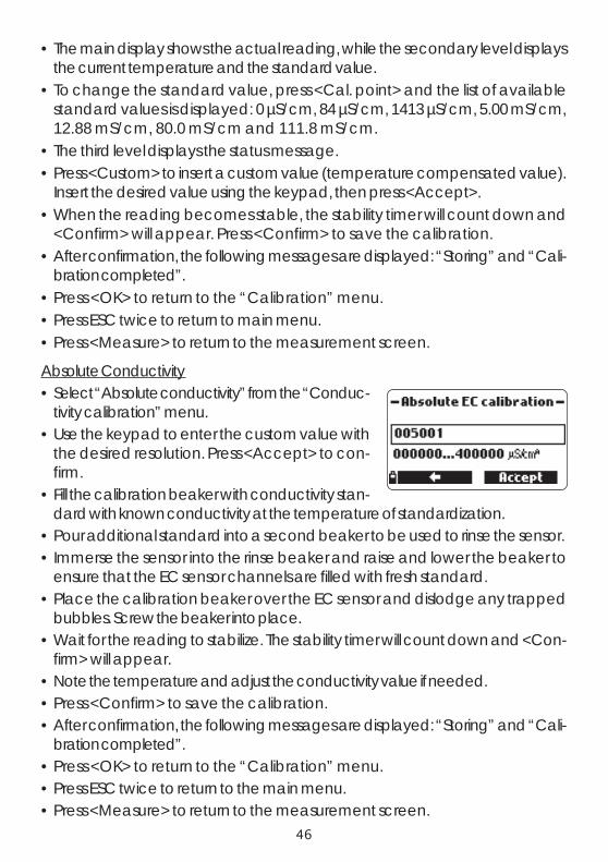
Absolute Conductivity• Select “Absolute conductivity” from the “Conduc-
tivity calibration” menu.• Use the keypad to enter the custom value with
the desired resolution. Press <Accept> to con-firm.
• Fill the calibration beaker with conductivity stan-dard with known conductivity at the temperature of standardization.
• Pour additional standard into a second beaker to be used to rinse the sensor.• Immerse the sensor into the rinse beaker and raise and lower the beaker to
ensure that the EC sensor channels are filled with fresh standard.• Place the calibration beaker over the EC sensor and dislodge any trapped
bubbles. Screw the beaker into place.• Wait for the reading to stabilize. The stability timer will count down and <Con-
firm> will appear.• Note the temperature and adjust the conductivity value if needed.• Press <Confirm> to save the calibration.• After confirmation, the following messages are displayed: “Storing” and “Cali-
bration completed”.• Press <OK> to return to the “Calibration” menu.• Press ESC twice to return to the main menu.• Press <Measure> to return to the measurement screen.

47
SalinityThe measurement of salinity is based on the Practical Salinity Scale which usesthe EC measurement. If the user has a standard with known PSU value it may beused to calibrate the conductivity sensor.• Select “Salinity” from the “Conductivity calibra-
tion” menu.• Use the keypad to enter the known salinity value
of the calibration solution. Press <Accept> toconfirm.
• Fill the calibration beaker with salinity standard of known value.• Pour additional standard into a second beaker to be used to rinse the sensor.• Immerse the sensor into the rinse beaker and raise and lower the beaker to
ensure that the EC sensor channels are filled with fresh standard.• Place the calibration beaker with standard over the EC sensor and dislodge
any trapped gas bubbles. Screw the beaker into place.• Wait for the reading to stabilize. The stability timer will count down and <Con-
firm> will appear.• Note the temperature and adjust the salinity value if needed.• Press <Confirm> to save the calibration.• After confirmation, the following messages are displayed: “Storing” and “Cali-
bration completed”.• Press <OK> to return to the “Calibration” menu.• Press ESC twice to return to the main menu.• Press <Measure> to return to the measurement screen.
Notes These procedures calibrate the slope value. To calibrate the offset, setthe calibration point at 0 µS/cm and repeat the procedure.If the temperature input is not within theacceptable range (0 to 50°C), the mes-sage “Invalid temperature” is displayed.If the conductivity input is not within theacceptable range, the message “Wrongstandard” is displayed.

48
7.7 TURBIDITY CALIBRATION
From the “Calibration” menu select “Singleparam. calibration” and then “Turbiditycalibration”. The display shows two options:“Calibrate turbidity” and “Restore factory calib”.The Hanna turbidity sensor conforms to ISO7027 standards which specifies the anglebetween the emitted and detected light and the light source wavelength. Forbest results perform a three point calibration at 0.0, 20.0, and 200.0 FNU.Although the basis of calibration for this measurement is the standard Formazin,from a practical point of view, these standards require daily preparation. Asecondary standard based upon polystyrene beads is a more practical approach.See APPENDIX D – Accessories for information regarding Hanna calibrationsolutions.
Note Turbidity standard formulations made with polystyrene beads areinstrument specific and cannot be swapped with standards made foranother turbidity sensor model.
Verify the sensor is clean before calibrating. The use of the HI 7698293 calibrationbeaker is required for this procedure.Calibration is required every time the sensor is replaced and is recommended tobe part of yearly validation of your system.
7.7.1 Preparation
Pour quantities of selected standard solutions into clean beakers for rinse. Fillthe HI 7698293 calibration beaker with the zero standard. Submerse the turbiditysensor into zero rinse beaker and then shake off excess solution. Place the sensorinto the calibration beaker. It is extremely important that no bubbles are presenton the optical area. Gentle agitation of sensor or beaker may be required todislodge bubbles before screwing the beaker on fully.
7.7.2 Procedure
Select “Calibrate turbidity” from the menu.The measured value is shown on the main partof the display, while the standard value appearson the secondary level.• The current turbidity value, the standard value
and “Not ready...” are displayed and a stabilitytimer counts down.
• When the reading becomes stable, the display shows the “Ready” message.

49
• Press <Confirm> to accept the calibration point and to continue with secondstandard.
• Clean out the calibration beaker and refill with 20.0 FNU standard.• Immerse the sensor in the 20.0 FNU rinse beaker and then shake off excess
solution. Place the sensor into the 20.0 FNUcalibration beaker. Observe the precautionsnoted above for bubbles.
• When the reading is stable the display showsthe “Ready” message.
• Press <Confirm> to accept the secondcalibration point and to continue with third standard.
• Clean out the calibration beaker and refill with 200.0 FNU standard.• Immerse the sensor in the 200.0 FNU rinse beaker and then shake off excess
solution. Place the sensor into the 200.0 FNUcalibration beaker. Observe the precautionsnoted above for bubbles.
• When the reading is stable the display showsthe “Ready” message.
• Press <Confirm> to accept the third point andsave the calibration.
• After confirmation, the following messages are displayed: “Storing” and“Calibration completed”.
• Press <OK> to return to the “Calibration” menu.• To return to the main menu, press ESC twice.• Press <Measure> to return to the measurement screen.• To restore the factory calibration data, select the corresponding option in the
“Turbidity calibration” menu and then press <Select>.
Note The calibration procedure can be terminated after 1 or 2 points bypressing <ESC>. A single point calibration is only recommended toupdate the offset of a previous 2 or 3 point calibration. A 2 pointcalibration is only recommended when the expected turbidity readingsare below 40 FNU.
50
7.8 TEMPERATURE CALIBRATION
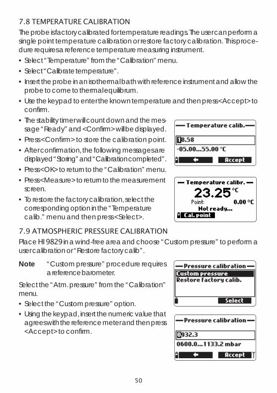
The probe is factory calibrated for temperature readings. The user can perform asingle point temperature calibration or restore factory calibration. This proce-dure requires a reference temperature measuring instrument.• Select “Temperature” from the “Calibration” menu.• Select “Calibrate temperature”.• Insert the probe in an isothermal bath with reference instrument and allow the
probe to come to thermal equilibrum.• Use the keypad to enter the known temperature and then press <Accept> to
confirm.• The stability timer will count down and the mes-
sage “Ready” and <Confirm> will be displayed.• Press <Confirm> to store the calibration point.• After confirmation, the following messages are
displayed “Storing” and “Calibration completed”.• Press <OK> to return to the “Calibration” menu.• Press <Measure> to return to the measurement
screen.• To restore the factory calibration, select the
corresponding option in the “Temperaturecalib.” menu and then press <Select>.
7.9 ATMOSPHERIC PRESSURE CALIBRATION
Place HI 9829 in a wind-free area and choose “Custom pressure” to perform auser calibration or “Restore factory calib”.
Note “Custom pressure” procedure requiresa reference barometer.
Select the “Atm. pressure” from the “Calibration”menu.• Select the “Custom pressure” option.• Using the keypad, insert the numeric value that
agrees with the reference meter and then press<Accept> to confirm.
51
• The stability counter will count down and the message “Ready” and “Confirm”will be displayed. Press <Confirm> to store the calibration point.
• After confirmation, the following messages are displayed: “Storing” and “Cali-bration completed”.
• Press <Measure> to return to the measurement screen.• Press <OK> to return to the “Calibration” menu.• To restore the factory calibration, select “Restore factory calib.” in the “Pressure
calibration” menu and press <Select>.

52
Chapter 8 - SYSTEM SETUP
From the main menu, select “System setup” andthen “Meter setup” or “Probe setup”.
8.1 METER SETUP
Note If the password protection is enabled,you will be required to enter the pass-word before any settings can be modi-fied.
8.1.1 Time
The meter uses a real time clock for logging. Thetime and time format are set in this function.Press <Modify> and set the time using the key-pad. Press <Accept> to save the time. When us-ing the 12 hour format, press A or P on the key-pad for AM or PM after you set the time.Press <Format> to change between 12 and 24hour formats. The default format is 24 hours.
8.1.2 Date
The date and date format are set in this function.Press <Modify> and set the date using the key-pad. Press <Accept> to save the date.Press <Format> to change between the avail-able date formats: DD/MM/YYYY, MM/DD/YYYY,YYYY/MM/DD, YYYY-MM-DD, MM-DD-YYYY,and DD-MM-YYYY. The default formatis YYYY/MM/DD.

53
8.1.3 Auto PoweroffThe Auto Poweroff function is used to save batterylife. After the set time is elapsed, the meter will:1. automatically switch off, if in normal measure-ment mode. Press On/Off to switch on again.2. enter a sleeping mode, if the continuous log-ging mode is selected with a logging interval of at least 30 seconds. The “AutoPoweroff” message and the <Wake up> softkey appear on the LCD; logging isnot stopped. Press <Wake up> to reactivate the display.
Available options are: Not used (disabled), 5, 10, 15, 20, 30 or 60 minutes.Press <Modify> to select the desired time interval. The default value is “not used”.8.1.4 Key BeepIf enabled, an acoustic signal sounds every timea key is pressed. A checked box indicates this func-tion has been enabled. The default setting is dis-abled.8.1.5 Error BeepIf enabled, an acoustic signal sounds every timean incorrect key is pressed, or when an error oc-curs. A checked box indicates this function hasbeen enabled. The default setting is disabled.8.1.6 Decimal SeparatorThe user can select the type of decimalseparator: “dot” or “comma”. Press the softkey toselect the desired option. The default setting is“dot”.8.1.7 LCD ContrastThe LCD contrast can be adjusted with this func-tion. Press <Modify> to enter this function. Usethe arrow keys to change the contrast level andpress <Accept> to save the new value. The de-fault value is 8.

54
8.1.8 Meter Password
The Meter Password protects against unauthorized configuration changes andlog data erasure. When implemented, many setting and functions cannot bemodified or viewed.To enable the password proceed as follows:• Highlight “Meter Password” and press <Modify>.• Enter the desired password in the text box and press <Accept>.
Note While typing, the characters are masked with a “*” (star) symbol.• The meter will require password confirmation. Retype the same password and
press <Accept> to confirm.• The meter returns to the “Meter Setup” menu. The checkbox corresponding to
the meter password is checked.To disable the password protection highlight “Meter Password” and press<Modify>, enter the password and then press <Disable>. “No password”appears in the text box. Press <Accept> to confirm.
8.1.9 Meter ID
The Meter ID may be used to uniquely identify ameter/operator. Press <Modify> and a text boxappears. Use the keypad to insert the desired al-phanumeric ID and press <Accept> to store theidentification. A maximum of 14 characters canbe used.
8.1.10 Language
The language used in the meter user interfacecan be changed. The default language is English.Please contact your local Hanna office for cur-rently available languages.

55
8.1.11 Restore factory settings
This function restores measurement settings to theiroriginal factory values. This includes measurementunits, coefficients, other measurement configura-tions and all logged data. The factory calibrationfor the sensor channels is not affected.• Select the “Restore factory settings” and press <Select>.• The meter will ask to confirm: press <Yes> to confirm or <No> to escape.8.2 PROBE SETUP
8.2.1 Probe IDThe probe can be labeled with an identificationcode: press <Modify> and a text box will be dis-played. Use the keypad to enter the desired al-phanumeric code and then press <Accept>.A maximum of 14 characters can be used.
8.2.2 Probe Password
The Probe Password protects the probe against unauthorized configurationchanges and log data erasure. When implemented, many setting and functionscannot be modified or viewed.To enable the password:• Highlight the “Probe Password” and press <Modify>.• Enter the desired password in the text box and press <Accept>.Note While typing, the characters are masked with “*” (star) symbols.
• The probe will require confirmation. Retype the same password and press <Ac-cept> to confirm.
• The meter returns to the “Probe Setup” menu. The checkbox corresponding tothe probe password is checked.
To disable the password, highlight the “Probe Password” and press <Modify>.Enter the password and then press <Disable>. “No password” appears in thetext box. Press <Accept> to confirm.

56
Chapter 9 - GPS MENU (optional)
HI 9829 model featuring GPS (Global Positioning System) is provided with abuilt-in 12 channel receiver and antenna to calculate meter position and tracklocations along with measurement data.The GPS has a position accuracy of 10 meters (30 ft).The GPS coordinates can be shown on the LCD together with up to 10 measure-ment parameters, and are recorded with logged data.
The GPS signal strength is always displayed through a 3 length antenna indica-tor on the bottom right corner of the LCD. If the antenna symbol is blinking, thesatellite acquisition is not yet completed or the signal strength is not sufficient.Signal strength can be improved by moving outdoors and away from buildingsand trees.The user can associate GPS coordinates withalphanumeric locations, which will be assignedto the logged data.• To enter the GPS menu, press <Menu> from
measurement mode and select “GPS menu”.
All locations / Nearby locations
These options display all stored locations. Se-lecting “Nearby locations” will filter out loca-tions that are further than 100 km (or 100 mi)from the current location. If a GPS signal hasbeen obtained, the distance from the currentposition to the nearby locations is also displayed.

57
Press <Info> to view the GPS coordinates of theselected location. Press <Delete> to erase theselected location.Press <New> to add a new location. Coordinatesfor a new location can be entered manually or byusing the current GPS coordinates.
Clear all locationsThis option deletes all locations. The meter will askfor confirmation before proceeding, by displayingthe message “All location information will beerased. Continue?”.Press <Yes> to confirm deletion or <No> to re-turn to the previous screen.
GPS power saveThis feature saves battery life by automaticallyswitching the GPS unit off when the meter is incontinuous logging mode with a logging intervalof at least 4 minutes. The GPS unit will turn offafter each measurement and turn on again 3minutes before the next measurement is taken.If the GPS unit cannot obtain a position fix withintwo minutes, it will keep the GPS on by disablingthe power save feature.
GPS statusThis screen displays the following GPS information:latitude and longitude of the current position, num-ber of acquired satellites, time elapsed since lastdetected position (if the GPS signal is not currentlyavailable).Pressing <GPS OFF> will disable the GPS unit.Pressing <GPS ON> will enable the GPS unit and show the GPS receiver modeland version.Since the power consumption of the GPS unit is significant, it is recommended toturn the GPS unit off when it is not needed.

58
Chapter 10 - STATUS
Useful information regarding the meter, probe (ifconnected) and GLP calibration data are avail-able for viewing by selecting “Status” from the mainmenu.
10.1 METER STATUS
Select “Meter Status” to display information relatedto the battery, logging, internal temperature,password, Meter ID, serial number and firmwareversion. Press [up] and [down] to scroll throughthe status screens. Press ESC to return to the“Status” menu.
10.2 PROBE STATUS
Select “Probe Status” to display information relatedto the probe type, connected sensors, battery level,logging (if logging probe), password, Probe ID,serial number and firmware version.• Press [up] and [down] to scroll through the sta-
tus screens.• Press ESC to return to the “Status” menu.
Note The probe status screen will automatically be displayed when the probesensor status has changed. If this occurs, the “Measurement Screen”and “Parameter Selection” softkeys are available (see Section 5.2).

59
10.3 GLP Data
GLP (Good Laboratory Practice) is a set of functions that allows the user to storeor recall data regarding the probe calibration. This feature also allows the userto associate readings with specific calibrations.To view GLP data select “GLP” from the “Status”menu. The complete list of available parametersappears. Select the desired parameter to view thestored GLP information.Note If no calibration data is available for the
selected parameter, the display showsthe message “No GLP data availablefor this measurement”. Press <OK> toreturn to the previous screen.
Note GLP data is stored for the last 5 cali-brations. This calibration history allowsthe user to detect when readings startto change and sensors may requirecleaning or replacement.
pH
• From the “GLP” menu, select the “pH” option.• Data regarding the last pH calibration will be
displayed: offset, acidic slope, basic slope, buff-ers used, time and date of the calibration.
• Use the arrow keys to scroll through the storeddata for the last 5 calibrations.
• Press ESC to return to the “GLP” menu.
Note A “C” label near the buffer value indi-cates a custom point, while an “H” in-dicates a HANNA standard buffervalue.If a quick calibration was performed,the buffer values are replaced with the “Quick calibration” indication.If no pH calibration has been performed or if calibration was clearedusing the the “Restore factory calib.” option the offset and slope valuesare set to default, and the message “Factory calibration” is displayed.Press <ESC> to return to the previous screen.
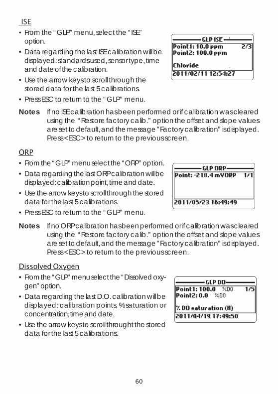
60
ISE
• From the “GLP” menu, select the “ISE”option.
• Data regarding the last ISE calibration will bedisplayed: standards used, sensor type, timeand date of the calibration.
• Use the arrow keys to scroll through thestored data for the last 5 calibrations.
• Press ESC to return to the “GLP” menu.
Notes If no ISE calibration has been performed or if calibration was clearedusing the “Restore factory calib.” option the offset and slope valuesare set to default, and the message ”Factory calibration” is displayed.Press <ESC> to return to the previous screen.
ORP
• From the “GLP” menu select the “ORP” option.• Data regarding the last ORP calibration will be
displayed: calibration point, time and date.• Use the arrow keys to scroll through the stored
data for the last 5 calibrations.• Press ESC to return to the “GLP” menu.
Notes If no ORP calibration has been performed or if calibration was clearedusing the “Restore factory calib.” option the offset and slope valuesare set to default, and the message ”Factory calibration” is displayed.Press <ESC> to return to the previous screen.
Dissolved Oxygen
• From the “GLP” menu select the “Dissolved oxy-gen” option.
• Data regarding the last D.O. calibration will bedisplayed: calibration points, % saturation orconcentration, time and date.
• Use the arrow keys to scroll throught the storeddata for the last 5 calibrations.

61
Notes A “C” label near the calibration point indicates a custom point, whilean “H” indicates a HANNA standard value.When the % D.O. range is calibrated, also the D.O. concentration rangeis calibrated, and vice versa.If no D.O. calibration has been performed or if calibration was clearedusing the “Restore factory calib.” option the offset and slope valuesare set to default, and the message ”Factory calibration” is displayed.Press <ESC> to return to the previous screen.
Conductivity
• From the “GLP” menu select the “Conductivity”option.
• Data regarding the last conductivity calibrationwill be displayed: calibration point, cell constantvalue, calibration type (conductivity, absoluteconductivity or salinity), time and date of the cali-bration.
• Use the arrow keys to scroll through the stored data for the last 5 calibrations.
Notes A “C” letter near the conductivity calibration indicates a custom point,while an “H” indicates a HANNA standard value.If no conductivity calibration has been performed or if calibration wascleared using the “Restore factory calib.” option the offset and slopevalues are set to default, and the message ”Factory calibration” is dis-played. Press <ESC> to return to the previous screen.
Turbidity
• From the “GLP” menu select the “Turbidity” option.• Data regarding the last turbidity calibration
will be displayed: standards used, time anddate of the calibration.
• Use the arrow keys to scroll through thestored data for the last 5 calibrations.
• Press <ESC> to return to the “GLP” menu.

62
Notes If no turbidity calibration has been performed or if calibration wascleared using the “Restore factory calib.” option the offset and slopevalues are set to default, and the message ”Factory calibration” is dis-played. Press <ESC> to return to the previous screen.
Temperature
• From the “GLP” menu select the “Temperature”option.
• Data regarding the last temperature calibrationwill be displayed: calibrated point, time and date.
• Use the arrow keys to scroll through the storeddata for the last 5 calibrations.
Notes If no user temperature calibration has been performed or if calibrationwas cleared using the “Restore factory calib.” option the offset value isset to default, and the message ”Factory calibration” is displayed. Press<ESC> to return to the previous screen.
Atmospheric Pressure
• From the “GLP” menu select “Atm. pressure”.• Data regarding the last atmospheric pressure
calibration will be displayed: custom calibrationpoint, time and date.
• Use the arrow keys to scroll through the storeddata for the last 5 calibrations.
Notes If no atmospheric pressure calibration has been performed or if cali-bration was cleared using the “Restore factory calib.” option the offsetvalue is set to default, and the message ”Factory calibration” is dis-played. Press <ESC> to return to the previous screen.

63
Chapter 11 - LOGGING MODE
The HI 9829 and HI 76x9829 system offers many logging options that canbe combined based on user needs. The following figures describe the avail-able logging options.

64

65
11.2 LOGGING ON METER• The data logged on the meter are organized by
lots. Up to 44,000 complete records can bestored in up to 100 lots. Each lot can store log-on-demand records and/or continuous recordswith different parameter configurations.
11.1 LOGGING MENU STRUCTURE
From measurement mode, press <Log> to access the log menu.

66
11.2.1 One Sample On Meter
Use this option to log one set of enabled measurement parameters to the metermemory.
• If there are no lots saved on the meter, press<New> to create a new lot. Use the keypad toenter the desired lot name and press <Accept>to confirm. Press <OK> to log the sample inthe selected lot.
• If there are existing lots on the meter, the meterwill suggest a lot to store the sample. Press<OK> to use the selected lot or <Options>to select a different lot. This will add the newsample data to an existing lot. A new lot canalso be created by pressing <New>. Press<OK> to log the sample in the selected lot.
• On the “Remarks” window, select <Yes> to goto the Remarks screen. Press <No> to skip thisoption. If <Yes> is selected, select a remarkfrom the list, or press <New> to create a newremark.
• On the “Read tag” screen, touch the location’siButton® with the meter’s tag reader. Otherwise,press <Skip> to skip this option.
• If the tag is touched, the associated ID will bedisplayed. If no ID is associated to the tag, theserial number is shown.
• Press <Tag ID> to insert an identification code for the tag, then press <OK>.
• To return to the measurement screen, press ESC.

67
11.2.2 Continuous meter log
• Select “Start meter log” to log the currently en-abled parameters at the set logging interval onthe meter.
• To set the logging interval, highlight “Start meterlog” and press <Options>. The log interval timecan set from 1 second to 3 hours. Press<Modify> and use the arrow keys and keypadto enter the desired log interval. Press <Accept>to confirm.
• Press <Select> to edit the lot, remark, or tag, seesection 11.4.
• To stop the meter log, enter the log menu andselect <Stop meter log> .
11.3 PROBE LOG (only for logging probes)• Select “Start probe log” to start a log with the
current settings. Press <Options> to change thelog settings.
Probe Log Options• To edit the lot remark, or tag, see section 11.5.• The log interval time can be set from 1 second
to 3 hours. Press <Modify> to change thelogging interval. Press <Accept> to confirm.
• “Select logging param.” to modify the parametersto be logged.
• To specify the log start time, highlight “Use starttime” and press <Enable>. Highlight “Log starttime” and press “Select”. Enter the desired timeand press <Accept> to confirm.
• To specify the log stop time, highlight “Use stoptime” and press <Enable>. Highlight “Log stoptime” and press <Select>. Enter the desired timeand press <Accept> to confirm.
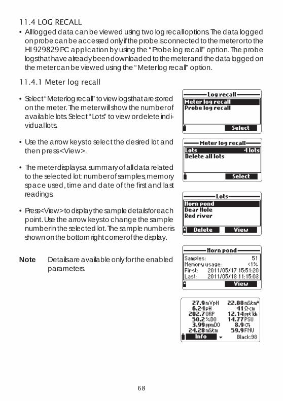
68
11.4 LOG RECALL• All logged data can be viewed using two log recall options. The data logged
on probe can be accessed only if the probe is connected to the meter or to theHI 929829 PC application by using the “Probe log recall” option. The probelogs that have already been downloaded to the meter and the data logged onthe meter can be viewed using the “Meter log recall” option.
11.4.1 Meter log recall
• Select “Meter log recall” to view logs that are storedon the meter. The meter will show the number ofavailable lots. Select “Lots” to view or delete indi-vidual lots.
• Use the arrow keys to select the desired lot andthen press <View>.
• The meter displays a summary of all data relatedto the selected lot: number of samples, memoryspace used, time and date of the first and lastreadings.
• Press <View> to display the sample details for eachpoint. Use the arrow keys to change the samplenumber in the selected lot. The sample number isshown on the bottom right corner of the display.
Note Details are available only for the enabledparameters.

69
• Press <Info> to see record information for the current sample (time & date,remark, location (only for model with GPS) and tag ID or serial number (ifavailable).)
• Press <Data> to return to the previous screen or <Jump> to select a differentsample in the same lot. When <Jump> is pressed, a text box appears to insertthe desired sample number.
• Press ESC to return to the menu.
• Choose “Plot” and the meter will create a list withall available parameters that can be plotted.
• Use the arrow keys to select the desired param-eter. Press <Select> to view the graph.
• Use the arrow keys to move the cursor in the graphand highlight a sample. The sample data are dis-played below the graph.
• Press ESC to return to the parameter list.
• Press ESC again to return to the menu.
Note The number of lot samples that can be plotted is limited by the display resolution. Toview a complete graph download data toPC.
Delete all lots• From ‘’Meter log recall’’ choose “Delete all lots”
and the meter will display the message “Do youwant to perform the current operation?”. Press<Yes> to delete or <No> to return to the previ-ous screen.
• To return to the “Log recall” menu, press ESC.
11.4.2 Probe log recall (Logging Probe only)
• Select “Probe log recall” to view and manage lotsthat are stored on the probe.
• Select ”Lots” to display a list of available lots onthe probe (logs have a Plog prefix).
• To view basic information about the highlightedlot, press <View>.

70
• After <View> is pressed, the meter displays alldata related to the selected lot: number ofsamples, memory space used, time and date ofthe first and the last readings.
• To see all the sample details press <Download>.When the download is completed, the log is nowstored on the meter and can be accessed fromthe ‘’Meter log recall’’ menu. The data can beviewed as described in ‘’Meter log recall’’ insection 11.4.1.
• The downloaded lots are not deleted from theprobe and are available for other downloads(e.g. HI 929829 PC application).
• If a probe log has been downloaded to themeter, a warning message will be displayed ifyou try to download it again.
Delete all lots• From ‘’Probe log recall’’, select “Delete all lots” and the meter will display the
message “Do you want to perform the current operation?”. Press <Yes> todelete or <No> to return to the previous screen.
• To return to the “Log recall” menu, press ESC.
Download all probe logs• From ‘’Probe log recall’’, select “Download all probe logs”. The meter will down-
load all lots to the meter.
11.5 LOG NOTES
11.5.1 Remarks
A remark can be associated with each sample. Themeter can store up to 20 remarks.• To add a remark, select “Log notes” from the Log
menu, and then select “Remarks”.• The display shows a list of stored remarks.• Press <New> to create a new remark, and use
the keypad to enter the new remark in the textbox.
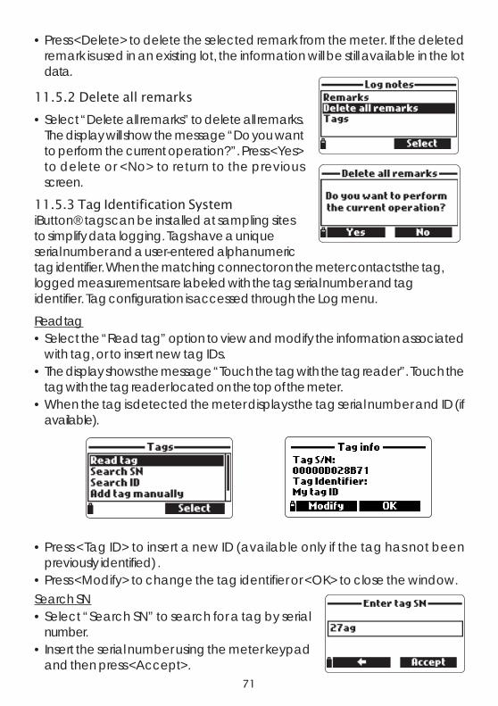
71
• Press <Delete> to delete the selected remark from the meter. If the deletedremark is used in an existing lot, the information will be still available in the lotdata.
11.5.2 Delete all remarks
• Select “Delete all remarks” to delete all remarks.The display will show the message “Do you wantto perform the current operation?”. Press <Yes>to delete or <No> to return to the previousscreen.
11.5.3 Tag Identification SystemiButton® tags can be installed at sampling sitesto simplify data logging. Tags have a uniqueserial number and a user-entered alphanumerictag identifier. When the matching connector on the meter contacts the tag,logged measurements are labeled with the tag serial number and tagidentifier. Tag configuration is accessed through the Log menu.
Read tag• Select the “Read tag” option to view and modify the information associated
with tag, or to insert new tag IDs.• The display shows the message “Touch the tag with the tag reader”. Touch the
tag with the tag reader located on the top of the meter.• When the tag is detected the meter displays the tag serial number and ID (if
available).
• Press <Tag ID> to insert a new ID (available only if the tag has not beenpreviously identified) .
• Press <Modify> to change the tag identifier or <OK> to close the window.Search SN• Select “Search SN” to search for a tag by serial
number.• Insert the serial number using the meter keypad
and then press <Accept>.

72
• The tag information window will appear. Press <OK> to return to the previousscreen or <Modify> to modify the tag ID.
Note If the typed SN is not stored in memory, the warning message “SN notfound” will be displayed.
Search ID• Select “Search ID” to search for a tag by ID.• Enter the identification code using the meter key-
pad and then press <Accept>.• The tag information window will appear. Press
<OK> to return to the previous screen or<Modify> to modify the tag ID.
Note If the inserted ID is not present in memory, a warning message will bedisplayed.
Add tag manually• Select “Add tag manually” to enter an ID code for a tag without using the tag
reader (e.g. if the tag is not physically available).• Enter the tag serial number using the meter key-
pad and then press <OK>.• Enter the ID code for the tag and then press
<OK>.• The meter will now display the new tag informa-
tion.
Clear tag memory• Select “Clear tag memory” to clear all tag information from the meter memory.
• The message “Do you want to perform the current operation?” appears.• Press <Yes> to confirm or <No> to return to the previous screen.• To return to measurement mode, press ESC.

73
Chapter 12 - PC CONNECTION MODE
The logged data from a probe or meter can be transferred to a PC using theHI 929829 Windows® compatible application software. HI 929829 offers avariety of features and on-line-help is available.HI 929829 allows data to be imported into most spreadsheet programs (e.g.Excel©, Lotus 1-2-3©). After the data has been imported into a spreadsheet, allfeatures of the spreadsheet program can be used to analyze and graph thedata.HI 929829 will automatically generate a map for samples logged with GPScoordinates. HI 929829 uses an external GPS tracking software such asGoogle™ Maps to view locations where measurements have been taken, there-fore an internet connection is required to use this function.
12.1 SOFTWARE INSTALLATION
• Insert the installation CD into the PC.• The software menu window should start automatically (if it does not, navigate
to the main CD folder and double-click “hi929829start.exe”). Click “Installsoftware” and follow the instructions.
12.2 METER TO PC CONNECTION
• With the meter OFF, disconnect the probe.• Connect the HI 7698291 USB adapter to the
meter and to a USB port on the PC.• Turn the meter ON and the message “PC con-
nected” will be displayed.• Run the HI 929829 application software.• Press Setting button on the top of the screen and select the measurement units
you which your data to appear with.• To access the meter data select the “Meter” button on the toolbar at the top of
the screen. The PC-Meter connection will be established and a new windowwill be displayed with meter data: status information (software version anddate, SN, ID, GPS info, battery level and free memory info), as well as a sum-mary of logged data lots. Both lots logged directly on the meter as well as lotslogged on a probe and downloaded to the meter can be saved to the PC bypressing the “Download lot” button after the desired lot is selected.
• Once the lot has been downloaded, all the logged samples can be viewed.
Windows® is a registered Trademark of “Microsoft Co.”GOOGLE™ is a registered trademark of Google, Inc. HANNA instruments® has no affiliation with Google™, Inc.

74
Meter to PC dataa. Select parameter unitsb. Select Meter from toolbarc. Select Lotd. Select Map

75
12.3 PROBE TO PC CONNECTION
• Connect the HI 76982910 adapter to the probe and to a USB port on the PC.• Run the HI 929829 application software.• To access the probe, press the “Probe” button from the toolbar on the top of
the screen.• A Communication Settings window will open. Select the correct COM port
and press OK.
Note The Windows “Device Manager” can be used to verify which COMport number is used for connecting to the probe. Press START on theWindows® task bar and select “Control panel”. In the Control Panelselect “System”, “Hardware”, “Device Manager”, “Ports”. The Portsmenu shows the number of the virtual COM port associated with theHI 76982910 USB adapter.
• Once the PC-Probe connection has been established a new window is dis-played with probe data: status information (software version, SN, ConnectorStatus, Available Parameters, Password Protection and free memory info) aswell as available data lots.
• Select the desired lot and Press the “Download” button to download the datato the PC.
• Press the “GLP Info” button to get the probe GLP info.

76
Probe Info Screen
Lot Data Screen

77
HI 9829 displays error messages to aid in troubleshooting. Warnings are dis-played for most issues, while Errors are displayed for critical issues.See the calibration chapter for messages that can occur during calibration. Othermessages are listed below.
• “Log space full” appears when the metermemory is full and additional data cannot belogged or downloaded from a logging probe.Delete one or more lots from the meter (Log /Meter Log), or download and delete one ormore logs from the probe.
• “Low probe external power supply level! Probeparameters disabled”: the battery voltage sup-plied from the meter to the probe is too low andthe measurements could be adversely affected.All parameters set on probe are disabled. Pressleft soft key, check the connection between meterand probe. If the problem persists, contact theHANNA service center.
• “Power fault. Check the probe cable”: this mes-sage may appear when powering up the meterwith a probe connected. If the meter detects ahigh load on the probe connection this mes-sage is triggered. Check the probe cable. If theproblem persists, contact the HANNA servicecenter.
• “Language data not available”: this messageappears when powering up the meter if the lan-guage file is not seen by the meter. Restart themeter to verify this is a true meter error. If theproblem persists, contact the HANNA service center.
Chapter 13 - TROUBLESHOOTING / ERROR MESSAGES

78
• ‘’GPS error’’ (only for models with GPS): thecommunication with the internal GPS unit can-not be established. Switch the meter off and onagain, then retry. If the problem persists, removethe batteries, wait for 5 minutes and install themagain. If the problem persists, contact theHANNA service center.
• ‘’Dead meter battery!’’: This message appearsif the meter batteries are too low to power themeter and it will automatically turn off. Con-nect the charger if using rechargeable C bat-teries or replace the alkaline batteries to con-tinue.
• ‘’Insert rechargeable batteries and slide batteryselector switch to the down position.’’: This mes-sage appears when non-rechargeable alkalinebatteries are installed on the meter and/ or thebattery selector switch in is the wrong position,and the user is attempting to charge then bat-teries.
• ‘’Dead probe battery!’’: This message appearsif the logging probes batteries are not supply-ing enough voltage to power the logging probe.Replace the probe batteries.
• ‘’User data corrupted!’’: This message appearswhen powering up the user data stored on meterare corrupted. Restart the meter. If the problempersists, contact the HANNA service center.

79
• ‘’Warning x’’: Any other warning that appears at power-on is identified usinga numeric code. Restart the meter. If the problem persists, contact the HANNAservice center. Some meter/probe features can be accessed but with no guar-antee.
• ‘’Errors x’’: Any critical errors that appear are identified using a numeric code,and the meter is automatically switched off. Contact the HANNA service cen-ter.

80
APPENDIX A - PROBE MAINTENANCE
The HI 7698292 probe maintenance kit includes HI 7042S (electrolyte solu-tion for D.O. sensor), spare membranes with o-rings for D.O. sensor, a smallbrush for cleaning EC , o-rings for sensor connectors and a syringe with greaseto lubricate these o-rings.
General Maintenance
• Inspect all sensor connectors for corrosion and replace sensors if necessary.• Inspect sensor o-rings for nicks or other damage and replace sensor if neces-sary. Lubricate only with grease from kit.
Use only the supplied grease as some lubricants can cause theo-rings to expand or affect the turbidity calibration standards.
• After prolonged storage or cleaning, calibration of the sensors is required.• After use rinse the probe with tap water and dry it. The pH electrode bulb must
be kept moist. Dry the D.O., EC and EC/Turbidity sensors. Dry ISE sensors andreturn to their storage caps if they will not be used for a period of time.
• Check GLP data under “Status” to ensure the sensor is still functioningproperly.
pH and pH/ORP Sensor Maintenance
• Remove the sensor protective cap. Do not be alarmed if any salt deposits arepresent. This is normal with pH/ORP electrodes and they will disappear whenrinsed with water.
• Shake down the sensor as you would do with a clinical thermometer to eliminateany air bubbles inside the glass bulb.
• If the bulb and/or junction are dry, soak the electrode in HI 70300 storagesolution for at least one hour.
• To ensure a quick response time, the glass bulb and the junction should be keptmoist and not allowed to dry. Store the sensor with a few drops of HI 70300storage solution or pH 4.01 buffer in the protective cap. Tap water may also be usedfor a very short period (few days).
Never use distilled or deionized water to store pH sensors
• Inspect the sensor for scratches or cracks. If any are present, replace the sensor.• Cleaning procedure: clean the sensor frequently by soaking it for 1 minute in
HI 70670 or HI 70671 cleaning solution. After cleaning soak the sensor inHI 70300 storage solution before taking measurements.

81
D.O. Sensor Maintenance
For a top performance probe, it is recommended to replace the membrane every2 months and the electrolyte monthly.Proceed as follows:• Unscrew the membrane by turning it counterclockwise.• Rinse a spare membrane with some electrolyte while
shaking it gently. Refill with clean electrolyte.• Gently tap the cap over a surface to ensure that no air bubbles remain
trapped. Avoid touching the membrane.• With the sensor facing down, completely screw the cap clockwise. Some
electrolyte will overflow.
If any deposit scales the sensor, gently brush the sensor surface with the suppliedbrush, while paying attention to not damage the plastic body. Do not use the brushon the membrane.
EC Sensor Maintenance
• After every series of measurements, rinse the probe with tap water.• If a more thorough cleaning is required, clean the sensor with the supplied
brush or a non-abrasive detergent. Ensure that the two cylindrical holes in thesensor are free of foreign material.
EC/Turbidity Sensor Maintenance
• After every series of measurements, rinse the probe with tap water.• If a more thorough cleaning of the sensor is required, clean the EC cylindrical
holes in the sensor with the supplied brush or a non-abrasive detergent. En-sure that the two cylindrical holes are free of foreign material.
• Gently remove any material that is attached to the face of the turbidity sensortaking care to not scratch the optical windows. Use a soft cloth and non-abrasive detergent.
• If there are cracks or scratches on the optical windows, the EC/turbidity sensormust be replaced.
ISE Sensor Maintenance
• After measurements inspect o-ring, connector and body. Rinse ISE sensor withtap water to remove films or other coatings.
• Shake down the sensor as you would do with a clinical thermometer to eliminateany air bubbles.
• Soak the electrode in its corresponding 10 ppm calibration solution for at least1/2 hour prior to calibration. Store dry in protective cap when not in use.

82
• For long-term storage rinse the electrodes with water. Shake off the excesswater and replace the storage cap to prevent evaporation of the referenceelectrolyte.
• For chloride sensors (HI 7609829-11), if the sensor pellet appears tarnished,use a polishing strip to remove the oxidized surface. Cut off approximately a 1inch piece of the strip. Wet the frosted side with water and place against dam-aged surface. Place your thumb against the shiny backing and slowly rotateback and forth while applying gentle pressure.If dark deposits appear on thefrosted surface, move the paper slightly. Continue polishing until you are satis-fied with the surface. Rinse sensor with water.

83
APPENDIX B - PROBE DEPLOYMENT
The Hanna HI 76X0929 has been designed for a variety of water qualitymeasurements both in situ or in active deployments in urban or naturalwaters. The HI 9829 systems may be used for discrete spot sampling with ameter and the meter’s log on demand function, unattended with continuousmonitoring and logging from the meter, or unattended using a logging probe.These data are then downloaded to a meter or PC and can be plotted withlogging software to obtain the graphical log needed for interpretation of theessential physical property of the aqueous body of water.In all of these deployment situations data quality is dependent upon the sitelocation, service intervals, amount of coatings, sedimentation and vegetation,and the actual installation. The probe may be installed in a horizontal bank(fixed installation) or a vertical suspension. The maximum depth rating of 20 m(65’) for the probe should be adhered to. (Note: actual sensor specificationsmay be less). The location must be accessible for the duration of the measurement(consider seasonal flooding, freezing and other acts of nature) when selecting asite. Many conditions may affect the quality of measurements. Select aninstallation site that is representative of the water body being monitored. Avoidareas without adequate water circulation. To protect equipment it is best to avoidexposure to wind, foam, turbulence, air temperature gradients/sun, extendedperiods of high flow, extended periods of high sediment and floating debris. Thestandard operating procedures (SOP) for the data gathering must be upheld.This typically includes pre and post deployment checks of the sensors to validatedata gathered between calibrations, upholding service intervals, and followingany other site-specific procedures. Grab samples for laboratory analysis or spotsampling with another probe are addition ways to validate the measurementstaken by unattended continuous logging probes.The probe is suitable for installation in confined locations such as air vaults,river intakes, vertical wells, tanks, etc.. The streamline diameter of the probepermits insertion into 2" pipelines. Unlike probes that require a cable support foractive deployments the probe can be manually lowered and raised by the cabledue to it’s superior strength member.It is suitable for installation in open moving waters; rivers, streams, ditches(farmland drainage), conveyance canals, etc.. In these cases protecting the probefrom debris is important. If the probe is suspended from a pier or bridge positionit behind a support and anchor the cable/probe to a pipe.It is suitable for deployment in open waters; monitoring lakes, ponds, wetlandbasin, infiltration basins, bays. Schedule regular service to remove aquatic weedgrowth that may be interfering with representative water samples.
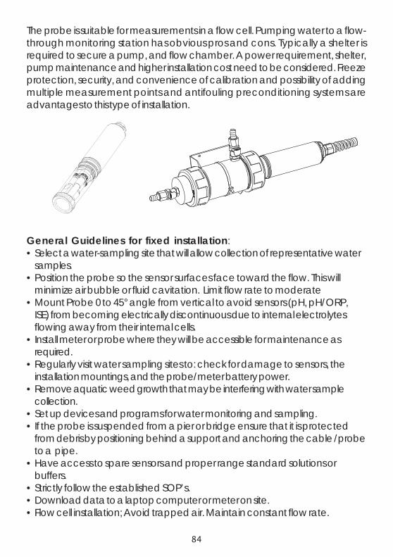
84
The probe is suitable for measurements in a flow cell. Pumping water to a flow-through monitoring station has obvious pros and cons. Typically a shelter isrequired to secure a pump, and flow chamber. A power requirement, shelter,pump maintenance and higher installation cost need to be considered. Freezeprotection, security, and convenience of calibration and possibility of addingmultiple measurement points and antifouling preconditioning systems areadvantages to this type of installation.
General Guidelines for fixed installation:• Select a water-sampling site that will allow collection of representative water
samples.• Position the probe so the sensor surfaces face toward the flow. This will
minimize air bubble or fluid cavitation. Limit flow rate to moderate• Mount Probe 0 to 45° angle from vertical to avoid sensors (pH, pH/ORP,
ISE) from becoming electrically discontinuous due to internal electrolytesflowing away from their internal cells.
• Install meter or probe where they will be accessible for maintenance asrequired.
• Regularly visit water sampling sites to: check for damage to sensors, theinstallation mountings, and the probe/meter battery power.
• Remove aquatic weed growth that may be interfering with water samplecollection.
• Set up devices and programs for water monitoring and sampling.• If the probe is suspended from a pier or bridge ensure that it is protected
from debris by positioning behind a support and anchoring the cable /probeto a pipe.
• Have access to spare sensors and proper range standard solutions orbuffers.
• Strictly follow the established SOP’s.• Download data to a laptop computer or meter on site.• Flow cell installation; Avoid trapped air. Maintain constant flow rate.

85
The HI 7609829-10 sensor is specified for 0.02 to 200 ppm (mg/L) NH4+-N
(equivalent to 0.026-260 ppm (mg/L) NH4+). Based on the corresponding
molecular weights of nitrogen and ammonium, the relationship is: NH4+-N
=(NH4+)(14/18) = (NH4
+) x 0.7778. NH4
+-N is also called ionized ammonia.
The sensor responds in a Nernstian manner (like a pH sensor) and produces avoltage that the meter converts to a concentration value.
APPENDIX C - ISE INFORMATION
This Appendix describes additional information about the ISE sensors used onthe HI76x9829 Probe.
HI 7609829-10: Ammonium selective electrode (ISE) is a combination liquidmembrane sensor used for the detection of free ammonium-nitrogen in fresh-water samples. The sensor utilizes a polymeric membrane made with ammo-nium ionophore in a PVC head and silver/silver chloride double junction gel filledreference electrode. The outer body of the sensor is the thermoplastic PEI. Thissensor is used in place of the pH.
The measurement of ammonium-nitrogen, NH4+-N is a useful tool in the
measurement of surface water contaminants such as tracing the source ofagricultural operations runoff or studying nutrient levels in natural waters.HI 7609829-10 is an ion selective sensor that responds to the free Ammoniumion. Ammonium ion is the ionized portion of the total ammonia concentrationand the amount present depends on pH. When the pH of the sample is below 8pH, the primary form of ammonia is ammonium ion. See figure below.The relationship is more complicated with increasing salinity but the two formstogether equal total ammonia.
D is trib u tio n d ia g ra m fo r a m m o n iu m io n /a m m o n ia v e ru s p H
T o ta l = N H 4 + + N H 3
0
0 .1
0 .2
0 .3
0 .4
0 .5
0 .6
0 .7
0 .8
0 .9
1
6 6 .5 7 7 .5 8 8 .5 9 9 .5 1 0 1 0 .5 1 1p H
NH
4+
9 .2 5 p H N H 4
+ = N H 3
N H 4+ io nize d fo rm
N H 3
m o le c ula r fo rm
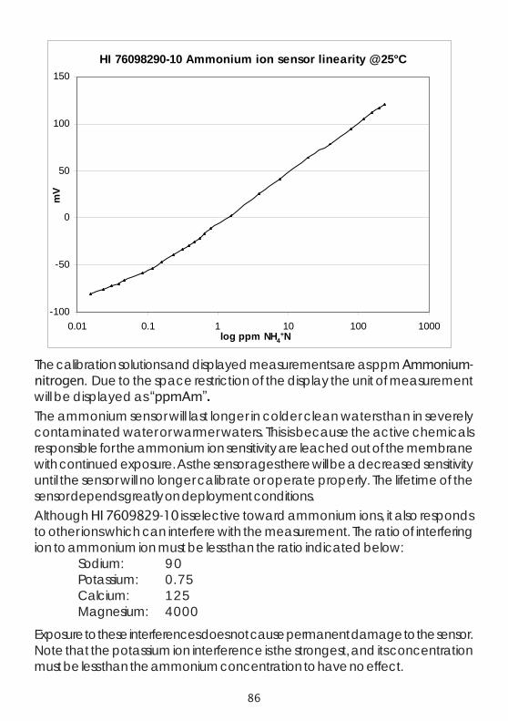
86
The calibration solutions and displayed measurements are as ppm Ammonium-nitrogen. Due to the space restriction of the display the unit of measurementwill be displayed as “ppmAm”.The ammonium sensor will last longer in colder clean waters than in severelycontaminated water or warmer waters. This is because the active chemicalsresponsible for the ammonium ion sensitivity are leached out of the membranewith continued exposure. As the sensor ages there will be a decreased sensitivityuntil the sensor will no longer calibrate or operate properly. The lifetime of thesensor depends greatly on deployment conditions.Although HI 7609829-10 is selective toward ammonium ions, it also respondsto other ions which can interfere with the measurement. The ratio of interferingion to ammonium ion must be less than the ratio indicated below:
Sodium: 90Potassium: 0.75Calcium: 125Magnesium: 4000
Exposure to these interferences does not cause permanent damage to the sensor.Note that the potassium ion interference is the strongest, and its concentrationmust be less than the ammonium concentration to have no effect.
HI 76098290-10 Ammonium ion sensor linearity @25°C
-100
-50
0
50
100
150
0.01 0.1 1 10 100 1000log ppm NH4
+N
mV

87
HI 7609829-11: Chloride ion selective electrode is a combination solid statesensor used for the detection of free chloride ions in freshwater samples. Thesensor utilizes a silver chloride pellet housed in a PEI head and a silver/silverchloride double junction gel filled reference electrode. The outer body of thesensor is the thermoplastic PEI. This sensor is used in place of the pH sensor inthe probe.
The measurement of chloride, Cl- is a useful tool in the measurement of surfacewater contaminants such as tracing the source of roadway run off or studyingnaturally occurring chloride levels in natural waters. HI 7609829-11 is an ionselective sensor that responds to the free chloride ion. Chloride ion is the ionizedform of chlorine.
HI 7609829-11 is specified for 0.6 to 200.0 ppm (mg/L) Cl-. The sensorresponds in a Nernstian manner (like a pH sensor) and produces a voltagethat the meter converts to a concentration value.
HI7609829-11 Chloride ion sensor linearity @ 25.0°C
0
50
100
150
200
250
3000.1 1 10 100 1000log ppm C l-
mV

88
The calibration solutions and displayed measurements are as ppm Chlorideions. Due to the space restriction of the display the unit of measurement will bedisplayed as “ppmCl” (without charge).The chloride sensor will last longer in colder clean waters than in severelycontaminated water or warmer waters. This is because the external surface ofthe sensor responsible for the chloride ion sensitivity can react with watercontaminants or be leached out of the sensor with continued exposure. As thesensor ages there will be a decreased sensitivity until the sensor will no longercalibrate or operate properly. The lifetime of the sensor depends greatly ondeployment conditions.Although HI 7609829-11 is selective toward chloride ions, it also responds toother ions.The interfering ions sulfide, cyanide, and mercury ions must be absent.The interfering ion to Cl- ratio must be less than the ratio indicated below:
Iodine: 1.0Bromide: 3.5Carbonate: 3.5Hydroxide: 1.0Thiosulfate: 0.01

89
HI 7609829-12: Nitrate ion selective electrode is a combination liquid mem-brane sensor used for the detection of nitrate nitrogen in freshwater samples.The sensor utilizes a polymeric membrane made with nitrate ionophore in a PVChead and a silver/silver chloride double junction gel filled reference electrode.The outer body of the sensor is the thermoplastic PEI. This sensor is used in placeof the pH sensor in the probe.The measurement of Nitrate-Nitrogen, NO3
--N is a useful tool in the measurementof surface water contaminants such as tracing the source of agriculturaloperations runoff or studying nutrient levels in natural waters. HI 7609829-12is an ion selective sensor that responds to the free nitrate ion.
Although all forms of nitrogen including nitrogen gas (N2) are interconvertiblewithin the nitrogen cycle as a function of oxidation state, the nitrate sensor onlydetects the ionized form.HI 7609829-12 is specified for 0.62 to 200 ppm (mg/L) NO3
--N (equivalentto 2.74 - 885.6 ppm (mg/L) NO3
-). Based on the corresponding molecularweights of nitrogen and nitrate, the relationship is: NO3
--N =(NO3-)(14/
62)=(NO3-) x 0.2258.
The sensor responds in a Nernstian manner (like a pH sensor) and produces avoltage that the meter converts to a concentration value.
HI 7609829-12 Nitrate ion sensor linearity@ 25°C
100
150
200
250
300
3500.1 1 10 100 1000log ppm NO3
--N
mV

90
The calibration solutions and displayed measurements are as ppm Nitrate-nitrogen. Due to the space restriction of the display the unit of measurementwill be displayed as “ppmNi”.The nitrate sensor will last longer in colder clean waters than in severelycontaminated water or warmer waters. This is because the active chemicalsresponsible for the nitrate ion sensitivity are leached out of the membrane withcontinued exposure. As the sensor ages there will be a decreased sensitivity untilthe sensor will no longer calibrate or operate properly. The lifetime of the sensordepends greatly on deployment conditions.Although HI 7609829-12 is selective toward nitrate ions, it also responds toother ions which can interfere with the measurement. Organic solvents andcationic detergents must be absent. Chloride has the largest interference fornatural waters.The ratio of interfering ion to nitrate ion must be less than the ratio indicatedbelow:
Fluoride: 300 Nitrite: 4Chloride:100 Iodide: 0.01Carbonate: 4 Perchlorate: 0.0045

91
APPENDIX D - ACCESSORIES
METERS (packed in carton box, no probe)HI 9829-01 Meter only, manual, charging cable adapter for 115VACHI 9829-02 Meter only, manual, charging cable adapter for 230VACHI 98290-01 HI 9829 with GPS, manual, charging cable adapter for
115VACHI 98290-02 HI 9829 with GPS, manual, charging cable adapter
for 230VAC
PROBES (packed in carton box, without sensors)
HI 7609829/4 HI 7609829 probe for pH/pH+ORP/ISE, D.O., EC,temperature with HI 7698295 short protective shield and4 meter (13.1’) cable
HI 7609829/10 HI 7609829 probe for pH/pH+ORP/ISE, D.O., EC,temperature with HI 7698295 short protective shield and10 meter (33’) cable
HI 7619829/4 HI 7609829 probe for pH/pH+ORP/ISE, D.O., EC/EC+turbidity, temperature with HI 7698296 longprotective shield and 4 meter (13.1’) cable
HI 7619829/10 HI 7609829 probe for pH/pH+ORP/ISE, D.O., EC/EC+turbidity, temperature with HI 7698296 longprotective shield and 10 meter (33’) cable
HI 7629829/4 HI 7629829 logging probe for pH/pH+ORP/ISE, D.O.,EC, temperature with HI 7698295 short protective shieldand 4 meter (13.1’) cable
HI 7629829/10 HI 7629829 logging probe for pH/pH+ORP/ISE, D.O.,EC, temperature with HI 7698295 short protective shieldand 10 meter (33’) cable
HI 7639829/4 HI 7629829 logging probe for pH/pH+ORP/ISE, D.O.,EC/EC+turbidity, temperature with HI 7698296 longprotective shield and 4 meter (13.1’) cable
HI 7639829/10 HI 7629829 logging probe for pH/pH+ORP/ISE, D.O.,EC/EC+turbidity, temperature with HI 7698296 longprotective shield and 10 meter (33’) cable
Note: Probes with different cable length are available upon request.

92
METERS WITH PROBES (packed in carrying case with maintenance kit,charging adapter, sensors not included)
HI 98291-01 HI 9829 and HI 7629829/4 logging probe for pH/pH+ORP/ISE, D.O., EC, temperature with HI 7698295short protective shield and 4 meter (13.1’) cable, probemaintenance kit, manual, charging cable adapter,for 115VAC
HI 98291-02 Same as HI 98291-01, for 230VACHI 98292-01 HI 9829 and HI 7639829/4 logging probe for pH/
pH+ORP/ISE, D.O., EC/EC+turbidity, temperature withHI 7698296 long protective shield and 4 meter (13.1’) cable,probe maintenance kit, manual, charging cable adapter,for 115VAC
HI 98292-02 Same as HI 98292-01, for 230VACHI 98293-01 HI 9829 and HI 7629829/10 logging probe for pH/
pH+ORP/ISE, D.O., EC, temperature with HI 7698295 shortprotective shield and 10 meter (33’) cable, probe maintenancekit, manual, charging cable adapter, for 115VAC
HI 98293-02 Same as HI 98293-01, for 230VACHI 98294-01 HI 9829 and HI 7639829/10 logging probe for pH/
pH+ORP/ISE, D.O., EC/EC+turbidity, temperature withHI 7698296 long protective shield and 10 meter (33’) cable,probe maintenance kit, manual, charging cable adapter,for 115VAC
HI 98294-02 Same as HI 98294-01, for 230VACHI 98295-01 HI 98290 with GPS and HI 7629829/4 logging probe for
pH/pH+ORP/ISE, D.O., EC, temperature with HI 7698295short protective shield and 4 meter (13.1’) cable, probemaintenance kit, manual, charging cable adapter, for 115VAC
HI 98295-02 Same as HI 98295-01, for 230VACHI 98296-01 HI 98290 with GPS and HI 9829 and HI 7639829/4 logging
probe for pH/pH+ORP/ISE, D.O., EC/EC+turbidity,temperature with HI 7698296 long protective shield and 4meter (13.1’) cable, probe maintenance kit, manual, chargingcable adapter, for 115VAC
HI 98296-02 Same as HI 98296-01, for 230VAC

93
HI 98297-01 HI 98290 with GPS and HI 7629829/10 logging probe forpH/pH+ORP/ISE, D.O., EC, temperature with HI 7698295short protective shield and 10 meter (33’) cable, probemaintenance kit, manual, charging cable adapter, for 115VAC
HI 98297-02 Same as HI 98297-01, for 230VACHI 98298-01 HI98290 with GPS and HI 7639829/10 logging probe for
pH/pH+ORP/ISE, D.O., EC/EC+turbidity, temperature withHI 7698296 long protective shield and 10 meter (33’) cable,probe maintenance kit, manual, charging cable adapter,for 115VAC
HI 98298-02 Same as HI 98298-01, for 230VAC
SENSORSHI 7609829-0 pH sensorHI 7609829-1 pH/ORP sensorHI 7609829-2 Dissolved Oxygen sensorHI 7609829-3 EC sensorHI 7609829-4 EC/Turbidity sensorHI 7609829-10 Ammonium ISEHI 7609829-11 Chloride ISEHI 7609829-12 Nitrate ISE
CABLES, CONNECTORS, ACCESSORIES
HI 7698290 Short calibration beakerHI 7698293 Long calibration beakerHI 7698295 Short probe shieldHI 7698296 Long probe shieldHI 7698294 Short flow cellHI 7698297 Long quick release flow cellHI 7698292 Probe maintenance kit with HI 7042S (electrolyte for D.O.
sensor), small brush, o-rings, syringe with grease tolubricate o-rings
HI 920005 iButton® with holder (5 pcs)

94
HI 929829 PC application softwareHI 7698291 USB cable PC to meterHI 76982910 USB cable PC to probeHI 710045 Power supply cableHI 710046 Cigarette lighter cableHI 710005 115 VAC/12 VDC adapter, US plugHI 710006 230 VAC/12 VDC adapter, European plugHI 710012 230 VAC/12 VDC adapter, UK plugHI 710013 230 VAC/12 VDC adapter, South African plugHI 710014 230 VAC/12 VDC adapter, Australian plugHI 710140 Hard carrying case for HI 9829
QUICK CALIBRATION SOLUTIONS
HI 9828-25 Quick calibration solution, 500 mLHI 9828-27 Quick calibration solution, 1 gal.
pH BUFFERS
HI 5004 pH 4.01 buffer solution, 500 mLHI 5046 pH 4.63 buffer solution, 500 mLHI 5005 pH 5.00 buffer solution, 500 mLHI 5006 pH 6.00 buffer solution, 500 mLHI 5068 pH 6.86 buffer solution, 500 mLHI 5007 pH 7.01 buffer solution, 500 mLHI 5074 pH 7.41 buffer solution, 500 mLHI 5008 pH 8.00 buffer solution, 500 mLHI 5009 pH 9.00 buffer solution, 500 mLHI 5091 pH 9.18 buffer solution, 500 mLHI 5010 pH 10.01 buffer solution, 500 mL
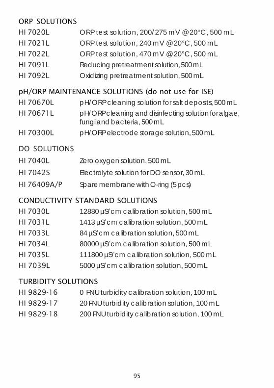
95
ORP SOLUTIONS
HI 7020L ORP test solution, 200/275 mV @ 20°C, 500 mLHI 7021L ORP test solution, 240 mV @ 20°C, 500 mLHI 7022L ORP test solution, 470 mV @ 20°C, 500 mLHI 7091L Reducing pretreatment solution, 500 mLHI 7092L Oxidizing pretreatment solution, 500 mL
pH/ORP MAINTENANCE SOLUTIONS (do not use for ISE)
HI 70670L pH/ORP cleaning solution for salt deposits, 500 mLHI 70671L pH/ORP cleaning and disinfecting solution for algae,
fungi and bacteria, 500 mLHI 70300L pH/ORP electrode storage solution, 500 mL
DO SOLUTIONS
HI 7040L Zero oxygen solution, 500 mLHI 7042S Electrolyte solution for DO sensor, 30 mLHI 76409A/P Spare membrane with O-ring (5 pcs)
CONDUCTIVITY STANDARD SOLUTIONS
HI 7030L 12880 µS/cm calibration solution, 500 mLHI 7031L 1413 µS/cm calibration solution, 500 mLHI 7033L 84 µS/cm calibration solution, 500 mLHI 7034L 80000 µS/cm calibration solution, 500 mLHI 7035L 111800 µS/cm calibration solution, 500 mLHI 7039L 5000 µS/cm calibration solution, 500 mL
TURBIDITY SOLUTIONS
HI 9829-16 0 FNU turbidity calibration solution, 100 mLHI 9829-17 20 FNU turbidity calibration solution, 100 mLHI 9829-18 200 FNU turbidity calibration solution, 100 mL

96
ISE SOLUTIONS
HI 9829-10 10 ppm ammonium (as N) standard for HI 7609829-10,25 x 25 mL sachet
HI 9829-11 100 ppm ammonium (as N) standard for HI 7609829-10,25 x 25 mL sachet
HI 9829-12 10 ppm chloride standard for HI 7609829-11,25 x 25 mL sachet
HI 9829-13 100 ppm chloride standard for HI 7609829-11,25 x 25 mL sachet
HI 9829-14 10 ppm nitrate (as N) standard for HI 7609829-12,25 x 25 mL sachet
HI 9829-15 100 ppm nitrate (as N) standard for HI 7609829-12,25 x 25 mL sachet

97
APPENDIX E - WARRANTY
All HANNA instruments® meters are guaranteed for two years (sensors,electrodes and probes for six months) against defects in workmanship andmaterials when used for their intended purpose and maintained according toinstructions.
This warranty is limited to repair or replacement free of charge. Damage due toaccident, misuse, tampering or lack of prescribed maintenance are not covered.
If service is required, contact the dealer from whom you purchased theinstrument. If under warranty, report the model number, date of purchase, serialnumber and the nature of the failure.
If the repair is not covered by the warranty, you will be notified of the chargesincurred.
If the instrument is to be returned to HANNA instruments®, first obtain aReturned Goods Authorization number from the Customer Service departmentand then send it with shipping costs prepaid.
When shipping any instrument, make sure it is properly packaged for completeprotection.
Recommendations for UsersBefore using this product, make sure that it is entirely suitable for the environment in which it is used.Operation of this instrument in residential areas could cause unacceptable interferences to radio and TVequipment, requiring the operator to take all necessary steps to correct interferences. The glass bulb at theend of the electrode is sensitive to electrostatic discharges. Avoid touching this glass bulb at all time. Tomaintain the EMC performance of equipment, the recommended cables noted in the instruction manualmust be used. Any variation introduced by the user to the supplied equipment may degrade the instruments'EMC performance. To avoid electrical shock, do not use these instruments when voltage at themeasurement surface exceed 24 Vac or 60 Vdc. To avoid damage or burns, do not perform anymeasurement in microwave ovens.

98

99

100
MAN9829 07/11Printed in EUROPE
(ROMANIA)
Hanna Instruments Inc.Highland Industrial Park584 Park East DriveWoonsocket, RI 02895 USA
Technical Support for CustomersTel. (800) 426 6287Fax (401) 765 7575E-mail [email protected]
Local Sales and Customer Service Office