HG0417 268-297 Outdoor-m10.qxp 6/23/05 10:46 AM Page 270 ...
4
Installing Outdoor Wiring: Cutaway View The outdoor circuit installation shown on the following pages gives step-by-step instructions for installing a simple outdoor circuit for light fix- tures and receptacles. The materials and tech- niques also can be applied to other outdoor wiring projects, such as running a circuit to a garage workshop, or to a detached shed or gazebo. Your outdoor wiring probably will be different from the circuit shown in this chapter. Refer to the circuit maps on pages 164 to 179 as a guide for designing and installing your own outdoor electrical circuit. Learn These Techniques for Installing Outdoor Wiring A: Install weatherproof decorative light fixtures with watertight threaded fittings (page 288). B: Use rigid metal or intermediate metallic con- duit (IMC) with threaded compression fittings (pages 280 to 281) to protect exposed wires and cables. C: Install a cast-aluminum switch box (page 283) to hold an outdoor switch. The box has a watertight coverplate with toggle lever built into it. D: Use weatherproof receptacle boxes made of cast aluminum with sealed coverplates and threaded fittings to hold outdoor receptacles (pages 280 to 281). A B C D
Transcript of HG0417 268-297 Outdoor-m10.qxp 6/23/05 10:46 AM Page 270 ...

Installing Outdoor Wiring:Cutaway View
The outdoor circuit installation shown on thefollowing pages gives step-by-step instructionsfor installing a simple outdoor circuit for light fix-tures and receptacles. The materials and tech-niques also can be applied to other outdoor wiringprojects, such as running a circuit to a garageworkshop, or to a detached shed or gazebo.
Your outdoor wiring probably will be differentfrom the circuit shown in this chapter. Refer tothe circuit maps on pages 164 to 179 as aguide for designing and installing your own outdoor electrical circuit.
Learn These Techniquesfor Installing Outdoor WiringA: Install weatherproof decorative light fixtureswith watertight threaded fittings (page 288).
B: Use rigid metal or intermediate metallic con-duit (IMC) with threaded compression fittings (pages280 to 281) to protect exposed wires and cables.
C: Install a cast-aluminum switch box (page 283) to hold an outdoor switch. The box has a watertightcoverplate with toggle lever built into it.
D: Use weatherproof receptacle boxes made of cast aluminum with sealed coverplates andthreaded fittings to hold outdoor receptacles (pages280 to 281).
A
B
C
D
HG0417_268-297_Outdoor-m10.qxp 6/23/05 10:46 AM Page 270
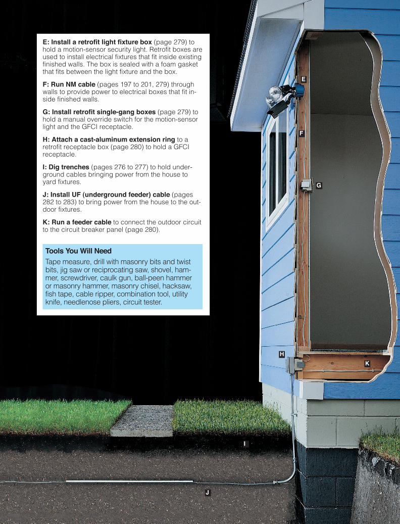
E: Install a retrofit light fixture box (page 279) tohold a motion-sensor security light. Retrofit boxes areused to install electrical fixtures that fit inside existingfinished walls. The box is sealed with a foam gasketthat fits between the light fixture and the box.
F: Run NM cable (pages 197 to 201, 279) throughwalls to provide power to electrical boxes that fit in-side finished walls.
G: Install retrofit single-gang boxes (page 279) tohold a manual override switch for the motion-sensorlight and the GFCI receptacle.
H: Attach a cast-aluminum extension ring to aretrofit receptacle box (page 280) to hold a GFCIreceptacle.
I: Dig trenches (pages 276 to 277) to hold under-ground cables bringing power from the house toyard fixtures.
J: Install UF (underground feeder) cable (pages282 to 283) to bring power from the house to the out-door fixtures.
K: Run a feeder cable to connect the outdoor circuitto the circuit breaker panel (page 280).
Tools You Will NeedTape measure, drill with masonry bits and twistbits, jig saw or reciprocating saw, shovel, ham-mer, screwdriver, caulk gun, ball-peen hammeror masonry hammer, masonry chisel, hacksaw,fish tape, cable ripper, combination tool, utilityknife, needlenose pliers, circuit tester.
E
F
G
H
I
J
K
HG0417_268-297_Outdoor-m10.qxp 6/23/05 10:46 AM Page 271
272
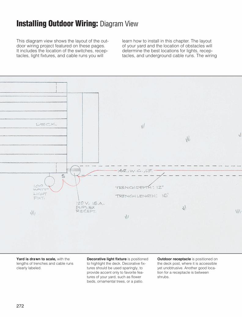
Installing Outdoor Wiring: Diagram View
This diagram view shows the layout of the out-door wiring project featured on these pages. It includes the location of the switches, recep-tacles, light fixtures, and cable runs you will
learn how to install in this chapter. The layout of your yard and the location of obstacles willdetermine the best locations for lights, recep-tacles, and underground cable runs. The wiring
Yard is drawn to scale, with thelengths of trenches and cable runsclearly labeled.
Decorative light fixture is positionedto highlight the deck. Decorative fix-tures should be used sparingly, toprovide accent only to favorite fea-tures of your yard, such as flowerbeds, ornamental trees, or a patio.
Outdoor receptacle is positioned onthe deck post, where it is accessibleyet unobtrusive. Another good loca-tion for a receptacle is betweenshrubs.
HG0417_268-297_Outdoor-m10.qxp 6/23/05 10:46 AM Page 272
273
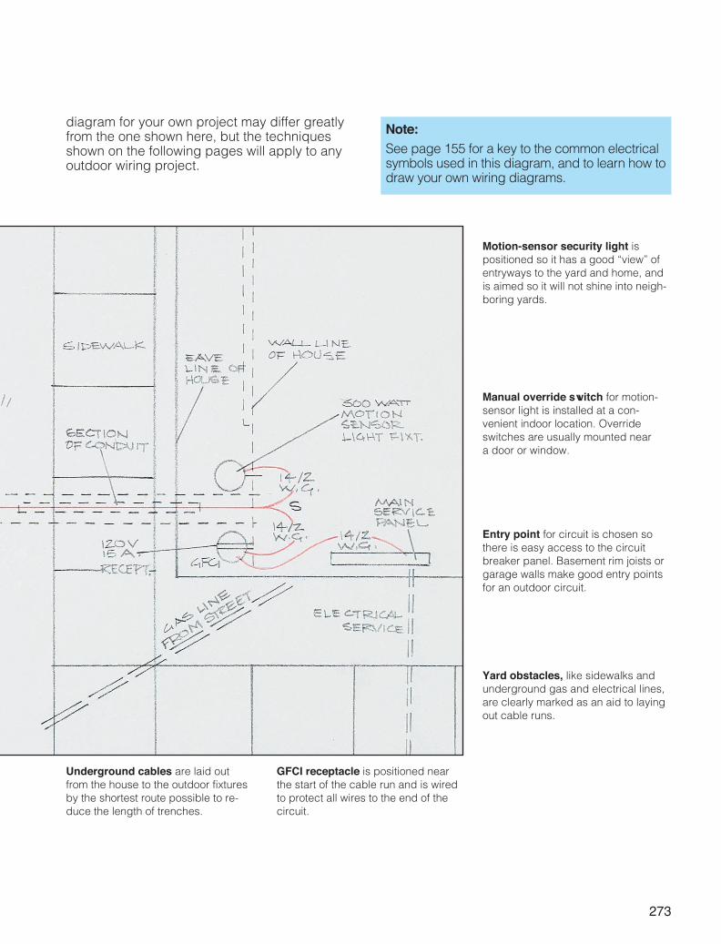
Note:See page 155 for a key to the common electricalsymbols used in this diagram, and to learn how todraw your own wiring diagrams.
Motion-sensor security light ispositioned so it has a good “view” ofentryways to the yard and home, andis aimed so it will not shine into neigh-boring yards.
Yard obstacles, like sidewalks andunderground gas and electrical lines,are clearly marked as an aid to layingout cable runs.
Underground cables are laid outfrom the house to the outdoor fixturesby the shortest route possible to re-duce the length of trenches.
GFCI receptacle is positioned near the start of the cable run and is wiredto protect all wires to the end of thecircuit.
diagram for your own project may differ greatlyfrom the one shown here, but the techniquesshown on the following pages will apply to anyoutdoor wiring project.
Manual override switch for motion-sensor light is installed at a con-venient indoor location. Overrideswitches are usually mounted near a door or window.
Entry point for circuit is chosen sothere is easy access to the circuitbreaker panel. Basement rim joists orgarage walls make good entry pointsfor an outdoor circuit.
HG0417_268-297_Outdoor-m10.qxp 6/23/05 10:46 AM Page 273