HF Series Generators - Frank's Hospital...
28
Technical Publication PI-1005R3 Pre-Installation HF Series Generators
Transcript of HF Series Generators - Frank's Hospital...

Technical PublicationPI-1005R3
Pre-InstallationHF Series Generators

HF Series Generators
Pre-Installation
PI-1005R3
REVISION HISTORY
REVISION DATE REASON FOR CHANGE
0 JUL 15, 2002 First edition
1 SEP 20, 2003 kW corrections for SHF-5xx model
2 FEB 17, 2004 New equipments
3 SEP 15, 2005 Revision of environmental and electrical requirements
This Document is the English original version, edited and supplied by the manufacturer.
The Revision state of this Document is indicated in the code number shown at the bottom of this page.
ADVISORY SYMBOLS
The following advisory symbols will be used throughout this manual. Theirapplication and meaning are described below.
DANGERS ADVISE OF CONDITIONS OR SITUATIONS THATIF NOT HEEDED OR AVOIDED WILL CAUSE SERIOUSPERSONAL INJURY OR DEATH.
ADVISE OF CONDITIONS OR SITUATIONS THAT IF NOTHEEDEDORAVOIDEDCOULDCAUSESERIOUSPERSONALINJURY, OR CATASTROPHIC DAMAGE OF EQUIPMENT ORDATA.
Advise of conditions or situations that if not heeded oravoidedcould causepersonal injury or damage to equipmentor data.
Note . Alert readers to pertinent facts and conditions. Notes representinformation that is important to know but which do not necessarilyrelate to possible injury or damage to equipment.

HF Series Generators
Pre-Installation
PI-1005R3i
TABLE OF CONTENTS
Section Page
1 INTRODUCTION 1. . . . . . . . . . . . . . . . . . . . . . . . . . . . . . . . . . . . . . . . . . . . . . . . . . . . . . . . .
1.1 Responsibility of Purchaser 1. . . . . . . . . . . . . . . . . . . . . . . . . . . . . . . . . . . . . . . . . .
2 PRE-INSTALLATION DATA 3. . . . . . . . . . . . . . . . . . . . . . . . . . . . . . . . . . . . . . . . . . . . . . .
3 ROOM REQUIREMENTS 11. . . . . . . . . . . . . . . . . . . . . . . . . . . . . . . . . . . . . . . . . . . . . . . . .
3.1 Environmental Requirements 11. . . . . . . . . . . . . . . . . . . . . . . . . . . . . . . . . . . . . . . . .
3.2 Electrical Requirements 11. . . . . . . . . . . . . . . . . . . . . . . . . . . . . . . . . . . . . . . . . . . . .
3.3 Line Powered Generators -- Power Line Requirements 12. . . . . . . . . . . . . . . . . . .
3.4 Line Powered Generators -- Recommended Wire Size 15. . . . . . . . . . . . . . . . . . .
3.5 Capacitor Assisted Generators -- Power Line Requirements 17. . . . . . . . . . . . . .
3.6 Capacitor Assisted Generators -- Recommended Wire Size 17. . . . . . . . . . . . . . .
3.7 Battery Powered generators -- Power Line Requirements 18. . . . . . . . . . . . . . . . .
3.8 Battery Powered Ggenerators -- Recommended Wire Size 18. . . . . . . . . . . . . . .
3.9 Interconnection and Grounding Requirements 19. . . . . . . . . . . . . . . . . . . . . . . . . .
3.10 Safety Devices 22. . . . . . . . . . . . . . . . . . . . . . . . . . . . . . . . . . . . . . . . . . . . . . . . . . . . .

HF Series Generators
Pre-Installation
PI-1005R3 ii

HF Series Generators
Pre-Installation
PI-1005R3 1
SECTION 1 INTRODUCTION
This Pre-Installation document provides the information and data needed toplan and qualify the customer site prior to equipment delivery and installation.
This document considers only the Generator and its associated components.Product information, environmental and electrical requirements are specified.
For system-related requirements, such as room layout, and systeminterconnections, refer to documentation provided with other subsystems.
1.1 RESPONSIBILITY OF PURCHASER
Site planning and preparation are the responsibilities of the purchaser. Thefollowing points should be considered fundamental to the customersPre-Installation activities; addition work may be needed depending on specificsite circumstances:
• Install required material prior the delivery of the system components.
• Complete room floor, ceiling and wall finish.
• Install conduit, duct, and raceway.
• Install proper size junction boxes with covers at locations specified in theinstallation plan.
• Install mains power of proper voltage output and adequate kVA rating.
• Install all safety devices according to this document and Local Codes.
• Provide current room dimensions, including hall way and entry doorsizes.
Complete and proper Pre-Installation will avoid delays andconfusion.
Note .

HF Series Generators
Pre-Installation
PI-1005R32
This page intentionally left blank.

HF Series Generators
Pre-Installation
PI-1005R3 3
SECTION 2 PRE-INSTALLATION DATA
This section provides product information and illustrations showing physicaldimensions, weight, mounting holes and normal access areas for cabling andservice. (Refer to Illustration 2-1.)
PHYSICAL CHARACTERISTICS
COMPONENTDIMENSIONS
WEIGHTCOMPONENTLength Width Height
WEIGHT
LINE POWERED GENERATORS
Vertical Generator Cabinetwith LF-RAC (LSS) or DRAC (HSS) 506 mm 468 mm 1101 mm 148 kg
Compact Generator Cabinet(for only 1 Tube (LSS)) 445 mm 360 mm 568 mm 72 kg
Compact Generator Cabinet(for 1 or 2 Tubes (LSS or HSS)) 592 mm 360 mm 690 mm 95 kg
CAPACITOR ASSISTED GENERATORS
Compact Generator Cabinetwith Capacitors Module 500 mm 360 mm 790 mm 108 kg
BATTERY POWERED GENERATORS
Compact--ESM Generator Cabinetwith Batteries Module 813 mm 436 mm 948 mm 235 kg
Compact--ESM Generator Cabinetwith Batteries Module (17 A/h batteries) 813 mm 436 mm 1223 mm 372 kg

HF Series Generators
Pre-Installation
PI-1005R34
PHYSICAL CHARACTERISTICS
COMPONENTDIMENSIONS
WEIGHTCOMPONENTLength Width Height
WEIGHT
STANDARD CONTROL CONSOLES
RAD Control Consolesw/o Pedestal 433 mm 298 mm 123 mm 8 kg
RAD Control Consoleswith Pedestal 433 mm 298 mm 1023 mm 22 kg
R&F Control Consolesw/o Pedestal 554 mm 360 mm 124 mm 12 kg
R&F Control Consoleswith Pedestal 554 mm 360 mm 1010 mm 35 kg
RAD Console Graphic Displaywith Handswitch support 545 mm 290 mm 50 mm 6 kg
RAD Console Graphic Displayw/o Handswitch support 430 mm 290 mm 50 mm 6 kg
Touch Screen Console with Handswitch support 468 mm 290 mm 114 mm 8 kgTouch Screen Console(TPC 10” or 12”) w/o Handswitch support 360 mm 290 mm 114 mm 8 kg
Optional Pedestal forRAD Console Graphic Display or Touch Screen Console 298 mm 236 mm 930 mm 10 kg
Note.-- Dimensions for no-standard Consoles are not indicated in this document.
TOUCH SCREEN CONSOLE AND PC UNIT
Touch Screen Console 400 mm 200 mm 400 mm 5 kg
PC Unit 480 mm 200 mm 400 mm 15 kg
PC Interface Box 130 mm 140 mm 46 mm 0.6 kg
Note.-- Specifications of Touch Screen Consoles and PC Units subject to change without notice.

HF Series Generators
Pre-Installation
PI-1005R3 5
METHOD OF MOUNTINGCOMPONENT NORMAL METHOD OF MOUNTING
Generator CabinetFloor freestanding, wall mounted or anchor to floor withfour M10 (3/8”) bolts.
Control Consoles Desk freestanding, wall mounted or anchor to an optional pedestal.
Note: Anchoring hardware should be field supplied. For seismic areas all components must be anchored,Local Standards should be applied.
MINIMUM RECOMMENDED FREE AREA FOR SERVICE ACCESS
COMPONENTSURFACE
COMPONENTLeft Side Right Side Front Rear Top Bottom
Generator Cabinet50 cm(20”)
50 cm(20”)
100 cm(40”)
--(see note)
Completelyfree --
Control Consoles10 cm(4”)
10 cm(4”)
Completelyfree
10 cm(4”)
Completelyfree --
Note: Ventilation conditions requires to keep a minimum free distance of 15 cm (6”) from both lateral sides of the GeneratorCabinet and also the same distance from the rear side when the Generator is provided with High Speed Starter (fans for thestarter module).

HF Series Generators
Pre-Installation
PI-1005R36
Illustration 2-1Generators
568
Wall and Floor Supports are options
Floor Support
WallS
upport
Generator
Cable Access
COMPACTGENERATOR(For only 1 Tube)
445
6767 57 57 57 5783
44150
3340
150
80206
8
28
200
251
435
110
224
40
315
19
427.5
67.5
702
422

HF Series Generators
Pre-Installation
PI-1005R3 7
Illustration 2-1 (cont.)Generators
690
COMPACTGENERATOR
(For 1 or 2 Tubes)
Floor Support
WallS
upport
Generator
Cable Access
Wall and Floor Supports are options
592
68 57 57 57 57
44150
3340
200
40280
828
250
336
580
105
234
40
462
19
427.5
67.5
827
422
6857 57 57 57
40

HF Series Generators
Pre-Installation
PI-1005R38
Illustration 2-1 (cont.)Generators
1101
VERTICALGENERATOR
1223
(with Batteries 17 A/h)
COMPACT-ESMGENERATOR
948
790
CAPACITORSGENERATOR
Cable Access
Cable Access
Cable Access
Cable Access
COMPACT-ESMGENERATOR

HF Series Generators
Pre-Installation
PI-1005R3 9
Illustration 2-1 (cont.)Consoles
400
PC UNIT
400
PC INTERFACE BOX
45
124
1010
123
1023
PEDESTAL (optional)
R&F CONSOLE
RAD CONSOLE
PEDESTAL (optional)
TOUCH SCREEN CONSOLE
Cable Access
Mounting Holes ø8
Cable Access
Mounting Holes ø8
Cable Access
FOR PC

HF Series Generators
Pre-Installation
PI-1005R310
Illustration 2-1 (cont.)Consoles
TOUCH SCREEN CONSOLES (TPC)
THESE CONSOLES CAN BE MOUNTED ON A TABLE SUPPORT, WALL SUPPORT OR PEDESTAL
RAD CONSOLES -- GRAPHIC DISPLAY
PEDESTAL
TABLE SUPPORT
WALL SUPPORT
HF Series Generators
Pre-Installation
PI-1005R3 11
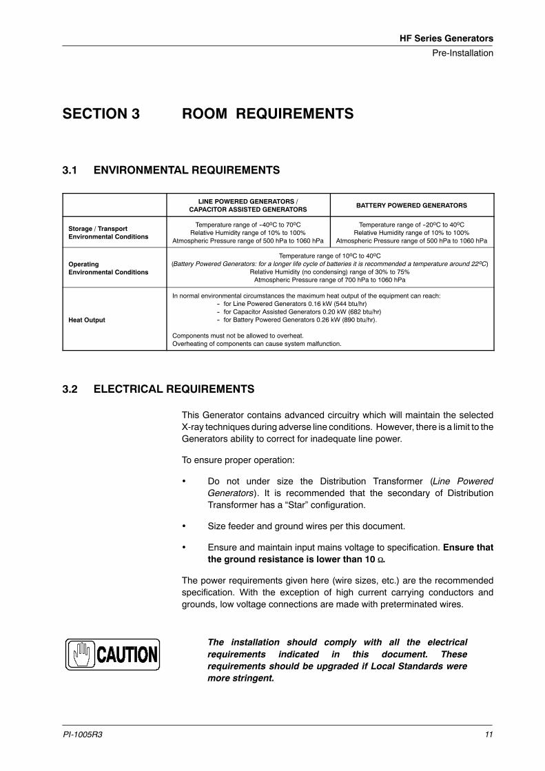
SECTION 3 ROOM REQUIREMENTS
3.1 ENVIRONMENTAL REQUIREMENTS
LINE POWERED GENERATORS /CAPACITOR ASSISTED GENERATORS
BATTERY POWERED GENERATORS
Storage / TransportEnvironmental Conditions
Temperature range of --40oC to 70oCRelative Humidity range of 10% to 100%
Atmospheric Pressure range of 500 hPa to 1060 hPa
Temperature range of --20oC to 40oCRelative Humidity range of 10% to 100%
Atmospheric Pressure range of 500 hPa to 1060 hPa
OperatingEnvironmental Conditions
Temperature range of 10oC to 40oC(Battery Powered Generators: for a longer life cycle of batteries it is recommended a temperature around 22oC)
Relative Humidity (no condensing) range of 30% to 75%Atmospheric Pressure range of 700 hPa to 1060 hPa
Heat Output
In normal environmental circumstances the maximum heat output of the equipment can reach:-- for Line Powered Generators 0.16 kW (544 btu/hr)-- for Capacitor Assisted Generators 0.20 kW (682 btu/hr)-- for Battery Powered Generators 0.26 kW (890 btu/hr).
Components must not be allowed to overheat.Overheating of components can cause system malfunction.
3.2 ELECTRICAL REQUIREMENTS
This Generator contains advanced circuitry which will maintain the selectedX-ray techniques during adverse line conditions. However, there is a limit to theGenerators ability to correct for inadequate line power.
To ensure proper operation:
• Do not under size the Distribution Transformer (Line PoweredGenerators). It is recommended that the secondary of DistributionTransformer has a “Star” configuration.
• Size feeder and ground wires per this document.
• Ensure and maintain input mains voltage to specification. Ensure thatthe ground resistance is lower than 10 Ω.
The power requirements given here (wire sizes, etc.) are the recommendedspecification. With the exception of high current carrying conductors andgrounds, low voltage connections are made with preterminated wires.
The installation should comply with all the electricalrequirements indicated in this document. Theserequirements should be upgraded if Local Standards weremore stringent.

HF Series Generators
Pre-Installation
PI-1005R312
3.3 LINE POWERED GENERATORS -- POWER LINE REQUIREMENTS
• Operation:
GENERATOR MODEL SHF-310 SHF-315 SHF-320 SHF-325 SHF-330 SHF-335
Max. Power kW 32 kW
Maximum mA 400 mA
Maximum kVp 125 kVp 150 kVp 125 kVp 150 kVp 125 kVp 150 kVp
Power Line A A B B C / D C / D
GENERATOR MODEL SHF-410 SHF-415 SHF-420 SHF-425 SHF-430 SHF-435
Max. Power kW 40 kW
Maximum mA 500 mA
Maximum kVp 125 kVp 150 kVp 125 kVp 150 kVp 125 kVp 150 kVp
Power Line A A B B C / D C / D
GENERATOR MODEL SHF-510 SHF-515 SHF-520 SHF-525 SHF-530 SHF-535
Maximum Power kW 50 kW
Maximum mA 640 mA (or 630 mA under special order)
Maximum kVp 125 kVp 150 kVp 125 kVp 150 kVp 125 kVp 150 kVp
Power Line A A B B C / D C / D
GENERATOR MODEL SHF-630 SHF-635 SHF-835
Maximum Power kW 64 kW (or 65 kW under special order) 80 kW
Maximum mA 640 mA (or 650 mA under special order) 800 mA (or 1000 mA under special order)
Maximum kVp 125 kVp 150 kVp 150 kVp
Power Line C / D C / D D (or E for 1000 mA)
POWER LINE
A B C D E
230 / 240 VAC,Single-Phase, 50 / 60 Hz
230 / 240 VAC,Three-Phase, 50 / 60 Hz
400 / 415 / 440 VAC,Three-Phase, 50 / 60 Hz
480 VAC,Three-Phase, 50 / 60 Hz
530 VAC,Three-Phase, 50 / 60 Hz
Line voltage automatic compensation: ±10%.
Maximum line regulation for maximum kVA demand: 5%.
NOTES: -- For lines at 210 VAC or below an auxiliary boost transformer is required to adequate the line voltage to theGenerator input.-- For 80 kW Generators operating with lines at 400 / 415 / 440 VAC an auxiliary boost transformer is required to adequatethe line voltage to 480 VAC (or 530 VAC).

HF Series Generators
Pre-Installation
PI-1005R3 13
• RMS line current during a X-ray exposure,minimum line power required,Generator stand-by consumption (W), the differential sensitivity (mA)and the thermomagnetic breaker should be:
LINE VOLTAGESINGLE-PHASE GENERATORS
LINE VOLTAGE32 kW 40 kW 50 kW
208 VAC * 192 A 240 A 300 A
230 VAC 174 A 217 A 272 A
240 VAC 167 A 208 A 260 A
Minimum kVA required Maximum kW x 1.25
Stand-by Consumption 500 W
Differential Sensitivity(Earth Leakage / Ground Fault) 30 mA
Differential, Thermomagnetic(Fuses) and Contactor
50% of the RMS line current(RMS = momentary line current based on 100 ms X-ray exposures)
NOTE: -- For lines at 210 VAC or below an auxiliary boost transformer is required to adequate the line voltage to theGenerator input.
LINE VOLTAGETHREE-PHASES GENERATORS
LINE VOLTAGE32 kW 40 kW 50 kW 64 kW (or 65 kW) 80 kW *
208 VAC * 111 A 138 A 173 A -- --
230 VAC 100 A 125 A 156 A
240 VAC 96 A 120 A 150 A -- --
400 VAC 58 A 72 A 90 A 115 A 144 A
415 VAC 55 A 69 A 87 A 111 A 139 A
440 VAC 52 A 65 A 82 A 105 A 135 A
480 VAC 48 A 60 A 75 A 96 A 120 A
Minimum kVA required Maximum kW x 1.25
Stand-by Consumption 500 W
Differential Sensitivity(Earth Leakage / Ground Fault) 30 mA
Differential, Thermomagnetic(Fuses) and Contactor
50% of the RMS line current(RMS = momentary line current based on 100 ms X-ray exposures)
NOTES: -- For lines at 210 VAC or below an auxiliary boost transformer is required to adequate the line voltage to theGenerator input.-- For 80 kW Generators operating with lines at 400 / 415 / 440 VAC an auxiliary boost transformer is required to adequatethe line voltage to 480 VAC (or 530 VAC).

HF Series Generators
Pre-Installation
PI-1005R314
• Maximum Power Line Impedance. The Impedance of the Power Line inthe installation must be lower than the maximum value indicated below:
LINE VOLTAGESINGLE-PHASE GENERATORS POWER
LINE VOLTAGE32 kW 40 kW 50 kW
208 VAC * 0.045 Ω 0.035 Ω 0.028 Ω
230 VAC 0.055 Ω 0.045 Ω 0.036 Ω
240 VAC 0.060 Ω 0.045 Ω 0.036 Ω
NOTES: -- The above values comply with the Standard IEC-60601.2.7.-- For lines at 210 VAC or below an auxiliary boost transformer is required to adequate the line voltage to theGenerator input.
LINE VOLTAGETHREE-PHASE GENERATORS POWER
LINE VOLTAGE32 kW 40 kW 50 kW 64 kW (or 65 kW) 80 kW *
208 VAC * 0.070 Ω 0.055 Ω 0.044 Ω N.A. N.A.
230 VAC 0.087 Ω 0.070 Ω 0.056 Ω N.A. N.A.
240 VAC 0.094 Ω 0.075 Ω 0.060 Ω N.A. N.A.
400 VAC 0.270 Ω 0.220 Ω 0.170 Ω 0.135 Ω 0.110 Ω
415 VAC 0.300 Ω 0.240 Ω 0.180 Ω 0.150 Ω 0.120 Ω
440 VAC 0.340 Ω 0.270 Ω 0.200 Ω 0.170 Ω 0.135 Ω
480 VAC 0.400 Ω 0.320 Ω 0.240 Ω 0.200 Ω 0.160 Ω
NOTES: -- The above values comply with the Standard IEC-60601.2.7.-- For lines at 210 VAC or below an auxiliary boost transformer is required to adequate the line voltage to theGenerator input.-- For 80 kW Generators operating with lines at 400 / 415 / 440 VAC an auxiliary boost transformer is required to adequatethe line voltage to 480 VAC (or 530 VAC).

HF Series Generators
Pre-Installation
PI-1005R3 15
3.4 LINE POWERED GENERATORS -- RECOMMENDED WIRE SIZE
Correct sizing of the feeder wires is critical to proper Generator operation.Wiresize is dependent on the Generator power, the line voltage and the distancefrom the Distribution Transformer to the Generator Cabinet. The maximumvoltage drop during an exposure must not exceed 5% of the nominal mainsvalue.
It is recommended that the Distribution Transformer (Hospital) used as powersource have at least a power of the 25%more than the maximum power of theX-ray Generator.
Recommended wire sizing is indicated in Table 3-1. These lengths aremeasured from the Distribution Transformer to the Room Electrical Cabinet(room disconnect). From the Room Electrical Cabinet to the GeneratorCabinet 16 mm2 (AWG 6) may be used as long as that length does notexceed 6 m (20 ft). The maximum wire size that can be connected to theGenerator Cabinet (Input Line Fuse Holder) is 35 mm2 (AWG 2).
Table 3-1Minimum Wire Size from Distribution Transformer to Room Electrical Cabinet
GENERATORLINE WIRE SIZE AT:
GENERATORLINE
VOLTAGE 15 m 30 m 45 m 60 m
208 VAC * 50 mm2 AWG 1/0 95 mm2 AWG 3/0 120 mm2 AWG 4/0 -- --
32 kW, 1φ 230 VAC 50 mm2 AWG 1/0 95 mm2 AWG 3/0 120 mm2 AWG 4/0 -- --, φ
240 VAC 50 mm2 AWG 1/0 95 mm2 AWG 3/0 120 mm2 AWG 4/0 -- --
208 VAC * 35 mm2 AWG 2 70 mm2 AWG 2/0 95 mm2 AWG 3/0 120 mm2 AWG 4/0
230 VAC 35 mm2 AWG 2 70 mm2 AWG 2/0 95 mm2 AWG 3/0 120 mm2 AWG 4/0
240 VAC 25 mm2 AWG 4 50 mm2 AWG 1/0 83 mm2 AWG 3/0 105 mm2 AWG 4/0
32 kW, 3φ 400 VAC 16 mm2 AWG 6 35 mm2 AWG 2 50 mm2 AWG 1/0 70 mm2 AWG 2/0, φ
415 VAC 16 mm2 AWG 6 35 mm2 AWG 2 50 mm2 AWG 1/0 70 mm2 AWG 2/0
440 VAC 16 mm2 AWG 6 35 mm2 AWG 2 50 mm2 AWG 1/0 50 mm2 AWG 1/0
480 VAC 16 mm2 AWG 6 25 mm2 AWG 4 35 mm2 AWG 2 50 mm2 AWG 1/0
208 VAC * 70 mm2 AWG 2/0 120 mm2 AWG 4/0 120 mm2 AWG 4/0 -- --
40 kW, 1φ 230 VAC 70 mm2 AWG 2/0 120 mm2 AWG 4/0 120 mm2 AWG 4/0 -- --, φ
240 VAC 70 mm2 AWG 2/0 105 mm2 AWG 4/0 120 mm2 AWG 4/0 -- --
208 VAC * 35 mm2 AWG 2 70 mm2 AWG 2/0 105 mm2 AWG 4/0 120 mm2 AWG 4/0
230 VAC 35 mm2 AWG 2 70 mm2 AWG 2/0 105 mm2 AWG 4/0 120 mm2 AWG 4/0
240 VAC 35 mm2 AWG 2 70 mm2 AWG 2/0 95 mm2 AWG 3/0 120 mm2 AWG 4/0
40 kW, 3φ 400 VAC 25 mm2 AWG 4 50 mm2 AWG 1/0 70 mm2 AWG 2/0 83 mm2 AWG 3/0, φ
415 VAC 25 mm2 AWG 4 35 mm2 AWG 2 70 mm2 AWG 2/0 70 mm2 AWG 2/0
440 VAC 16 mm2 AWG 6 35 mm2 AWG 2 50 mm2 AWG 1/0 70 mm2 AWG 2/0
480 VAC 16 mm2 AWG 6 35 mm2 AWG 2 50 mm2 AWG 1/0 70 mm2 AWG 2/0
NOTE: -- For lines at 210 VAC or below an auxiliary boost transformer is required to adequate the line voltage to theGenerator input.

HF Series Generators
Pre-Installation
PI-1005R316
Table 3-1 (cont.)Minimum Wire Size from Distribution Transformer to Room Electrical Cabinet
GENERATORLINE
WIRE SECTION AT:GENERATOR
LINEVOLTAGE 15 m 30 m 45 m 60 m
208 VAC * 83 mm2 AWG 3/0 120 mm2 AWG 4/0 -- -- -- --
50 kW, 1φ 230 VAC 83 mm2 AWG 3/0 120 mm2 AWG 4/0 -- -- -- --, φ
240 VAC 83 mm2 AWG 3/0 120 mm2 AWG 4/0 -- -- -- --
208 VAC * 50 mm2 AWG 1/0 95 mm2 AWG 3/0 120 mm2 AWG 4/0 -- --
230 VAC 50 mm2 AWG 1/0 83 mm2 AWG 3/0 120 mm2 AWG 4/0 -- --
240 VAC 50 mm2 AWG 1/0 83 mm2 AWG 3/0 120 mm2 AWG 4/0 -- --
50 kW, 3φ 400 VAC 25 mm2 AWG 4 50 mm2 AWG 1/0 70 mm2 AWG 2/0 95 mm2 AWG 3/0, φ
415 VAC 25 mm2 AWG 4 50 mm2 AWG 1/0 70 mm2 AWG 2/0 95 mm2 AWG 3/0
440 VAC 25 mm2 AWG 4 50 mm2 AWG 1/0 70 mm2 AWG 2/0 83 mm2 AWG 3/0
480 VAC 25 mm2 AWG 4 50 mm2 AWG 1/0 70 mm2 AWG 2/0 83 mm2 AWG 3/0
400 VAC 35 mm2 AWG 2 70 mm2 AWG 2/0 95 mm2 AWG 3/0 120 mm2 AWG 4/0
64 kW, 3φ415 VAC 35 mm2 AWG 2 70 mm2 AWG 2/0 83 mm2 AWG 3/0 120 mm2 AWG 4/0
64 kW, 3φ(or 65 kW, 3φ) 440 VAC 35 mm2 AWG 2 70 mm2 AWG 2/0 83 mm2 AWG 3/0 105 mm2 AWG 4/0
480 VAC 25 mm2 AWG 4 50 mm2 AWG 1/0 83 mm2 AWG 3/0 105 mm2 AWG 4/0
400 VAC 50 mm2 AWG 1/0 83 mm2 AWG 3/0 105 mm2 AWG 4/0 120 mm2 AWG 4/0
* 80 kW 3φ415 VAC 35 mm2 AWG 2 70 mm2 AWG 2/0 105 mm2 AWG 4/0 120 mm2 AWG 4/0
* 80 kW, 3φ440 VAC 35 mm2 AWG 2 70 mm2 AWG 2/0 105 mm2 AWG 4/0 120 mm2 AWG 4/0
480 VAC 35 mm2 AWG 2 70 mm2 AWG 2/0 95 mm2 AWG 3/0 120 mm2 AWG 4/0
NOTES: -- For lines at 210 VAC or below an auxiliary boost transformer is required to adequate the line voltage to theGenerator input.-- For 80 kW Generators operating with lines at 400 / 415 / 440 VAC an auxiliary boost transformer is required to adequatethe line voltage to 480 VAC (or 530 VAC).

HF Series Generators
Pre-Installation
PI-1005R3 17
3.5 CAPACITOR ASSISTED GENERATORS -- POWER LINE REQUIREMENTS
• Operation:
G Single-Phase at 100 / 110 / 120 / 208 / 230 / 240 VAC.G Line voltage automatic compensation: ±10%.G 50 Hz / 60 Hz.
• Thermomagnetic Interruptor / Circuit Breaker rating should be:
G 8 / 10 / 12.5 / 16 / 20 A (1P+N).
• Differential Sensitivity: 30 mA
• Minimum kW required: 2.0 kW
• Line Impedance should comply with Standard IEC-60601.2.7.
3.6 CAPACITOR ASSISTED GENERATORS -- RECOMMENDED WIRE SIZE
The minimum recommended wire size for the line voltage is:
LINE VOLTAGE WIRE SIZE
100 / 110 VAC 4 mm2 AWG 12
208 / 230 / 240 VAC 2.5 mm2 AWG 14

HF Series Generators
Pre-Installation
PI-1005R318
3.7 BATTERY POWERED GENERATORS -- POWER LINE REQUIREMENTS
• Operation:
G Single-Phase at 110 / 208 / 230 / 240 VAC.G Line voltage automatic compensation: ±15%.G 50 Hz / 60 Hz.
• Thermomagnetic Interruptor / Circuit Breaker rating should be:
G 10 A (1P+N curve type D).
• Differential Sensitivity: 30 mA
• Minimum kW required:
G without Stand-Alone option: 2.2 kWG with Stand-Alone option: 0.5 kW
• Line Impedance should comply with Standard IEC-60601.2.7.
3.8 BATTERY POWERED GENERATORS -- RECOMMENDED WIRE SIZE
The minimum recommended wire size for the line voltage is:
LINE VOLTAGE WIRE SIZE
110 VAC 4 mm2 AWG 12
208 / 230 / 240 VAC 2.5 mm2 AWG 14

HF Series Generators
Pre-Installation
PI-1005R3 19
3.9 INTERCONNECTION AND GROUNDING REQUIREMENTS
Every installation must be provided with a main line disconnect device(thermomagnetic breaker) and the remote disconnect devices required at allConsoles that are not located next to the line safety switch. (For moreinformation about interconnection and grounding refer to “Installation”document).
Illustration 3-1Interconnection Block Diagram for LINE POWERED GENERATORS
DISTRIBUTIONTRANSFORMER(Hospital, etc.)
ROOM ELECTRICAL CABINET WITHLINE SAFETY SWITCH(Provided by customer)
1
GENERATORCABINET
2
SERIAL CONSOLE or TOUCH SCREEN CONSOLE (TPC)Serial Comm.
HV CablesHV TRANSFORMER
POWER MODULE
LF-RAC (LS)
LV-DRAC (HS)
or
X-RAY TUBE
4
4
or
CONTROL CONSOLE3
TOUCH SCREEN PC PC INTERFACE BOX
or
Serial Comm.or
AUX. BOOST TRANSFORMERWHEN POWER LINES IS 210 VAC OR BELOW OR FOR80 kW GENERATORS WITH LINES AT 400 / 415 / 440 VAC
(Provided by customer)
For Serial Generators (RS232 / RS422): Console CPUs are locatedinside the Generator Cabinet and Interconnections are factory made.Only one cable (serial communication) from J5 of the Generator Cabinetshould be connected to the Serial Console, Touch Screen Console orPC Interface Box.
CABLE RUN FUNCTION REMARKS
1
Single or Three Phase Power.(1φ : 230 / 240 VAC)(3φ : 230 / 240 VAC or 400 / 415 / 440 / 480 VAC)
Connect to Room Electrical Cabinet according to the indicatedelectrical requirements. Customer supplied.
Ground.
electrical requirements. Customer supplied.
2
Single or Three Phase Power.(1φ : 230 / 240 VAC)(3φ : 230 / 240 VAC or 400 / 415 / 440 / 480 VAC)
Connect to Generator according to the indicated electricalrequirements. Install an Auxiliar Boost Transformer when it iseq i ed C sto e s pplied
Ground.
qrequired. Customer supplied.
3 Control Signals and Ground Cable quantity depends on the options installed (AEC, etc.)
Stator Supply.Provided with X ray Tube
4Ground.
Provided with X-ray Tube.
4Generator provided with LV-DRAC requires a shielded statorcable. (Refer to “Installation” document). Field supplied.
NOTES: -- For wire size refer to Section 3.4. Consult to Local Standards for feeder and ground wire size requirements.-- The system power ground point is located in the Generator Cabinet.
Note .

HF Series Generators
Pre-Installation
PI-1005R320
Illustration 3-2Interconnection Block Diagram for CAPACITOR ASSISTED GENERATORS
ROOM ELECTRICAL CABINETwith LINE SAFETY SWITCH
(Customer supplied)
1 1
(Customer supplied)
GENERATORCABINET
Serial Comm.
HV CablesHV TRANSFORMER
POWER MODULE
LF-RAC (LS)X-RAY TUBE 3
2
or
Serial Comm.or
SERIAL CONSOLE or TOUCH SCREEN CONSOLE (TPC)
CONTROL CONSOLE
TOUCH SCREEN PC PC INTERFACE BOX
For Serial Generators (RS232 / RS422): Console CPUs are locatedinside the Generator Cabinet and Interconnections are factory made.Only one cable (serial communication) from J5 of the Generator Cabinetshould be connected to the Serial Console, Touch Screen Console orPC Interface Box.
CABLE RUN FUNCTION REMARKS
1
Single-Phase Line.100 / 110 / 120 / 208 / 230 / 240 VAC.
The Unit is connected by a Line Plug.Power Line from a Room Electrical Cabinet with Safety Switch.1
Ground.
Power Line from a Room Electrical Cabinet with Safety Switch.Line plugs and cable are Customer supplied.
2 Control Signals and Ground Cable quantity depends on the options installed (AEC, etc.)
3Stator Supply.
Provided with X ray Tube3Ground.
Provided with X-ray Tube.
NOTES: -- For wire size refer to Section 3.6. Consult to Local Standards for feeder and ground wire size requirements.-- The system power ground point is located in the Generator Cabinet.
Note .

HF Series Generators
Pre-Installation
PI-1005R3 21
Illustration 3-3Interconnection Block Diagram for BATTERY POWERED GENERATORS
ROOM ELECTRICAL CABINETwith LINE SAFETY SWITCH
(Customer supplied)
1 1
(Customer supplied)
GENERATORCABINET
Serial Comm.
HV CablesHV TRANSFORMER
POWER MODULE
LF-RAC (LS)
LV-DRAC (HS)
or
X-RAY TUBE
3
3
or
2
or
Serial Comm.or
SERIAL CONSOLE or TOUCH SCREEN CONSOLE (TPC)
CONTROL CONSOLE
TOUCH SCREEN PC PC INTERFACE BOX
For Serial Generators (RS232 / RS422): Console CPUs are locatedinside the Generator Cabinet and Interconnections are factory made.Only one cable (serial communication) from J5 of the Generator Cabinetshould be connected to the Serial Console, Touch Screen Console orPC Interface Box.
CABLE RUN FUNCTION REMARKS
1
Single-Phase Line.110 / 208 / 230 / 240 VAC.
The Unit is connected by a Line Plug.Power Line from a Room Electrical Cabinet with Safety Switch.1
Ground.
Power Line from a Room Electrical Cabinet with Safety Switch.Line plugs and cable are Customer supplied.
2 Control Signals and Ground Cable quantity depends on the options installed (AEC, etc.)
Stator Supply.Provided with X ray Tube
3Ground.
Provided with X-ray Tube.
3Generator provided with LV-DRAC requires a shielded statorcable. (Refer to “Installation” document). Field supplied.
NOTES: -- For wire size refer to Section 3.8. Consult to Local Standards for feeder and ground wire size requirements.-- The system power ground point is located in the Generator Cabinet.
Note .

HF Series Generators
Pre-Installation
PI-1005R322
3.10 SAFETY DEVICES
Devices such as Safety Switch / Emergency Switch, Warning Light, and DoorInterlock Switch should be supplied and installed by the customer. (Refer toIllustration 3-4.)
SAFETY SWITCH / EMERGENCY SWITCH
The main Safety Switch should be installed in the Room Electrical Cabinet(Room Disconnect) (close to the Generator Cabinet), and provided with lightindicators for “Power On / Off”. It should be used for main disconnection, andlocated in an accessible place where it can be seen and controlled duringoperation and service.
Other Emergency Switches should be installed in accessible locations in theroom (near to the main entrance door or to the Control Console) for use in anemergency. They should be connected to the Room Electrical Cabinet (RoomDisconnect) so that they cut power to the Generator when they are activated.
The rating of these switches should be: 10 A, 500 VAC, NC.
DOOR INTERLOCK SWITCH
TheDoor InterlockSwitch indicates to the operatorwhenDoorways to theX-rayroom are open. It inhibits or not the X-ray generation, according to the LocalStandards and customer preferences.
This switch should be installed in the entrance door(s) and its connecting cableshould be routed to the Generator Cabinet.
WARNING LIGHT
The Warning Lights are signal lamps installed outside of the X-ray room (nearof the main entrance) that indicate:
1. The system is under voltage (red lamp “ON”).
2. X-ray exposure in process (yellow lamp “ON”) (for connection refer toInstallation document.)
The Warning Lights connection cables should be routed to the GeneratorCabinet.
In any case, the installation must be in compliance with the LocalRegulation.
Note .

HF Series Generators
Pre-Installation
PI-1005R3 23
Illustration 3-4Room Electrical Cabinet and Mains Connection
GEN
DCB
EM
EC
L
CR
EM
WL2
DIS
LEGEND
EC: Electrical Cabinet (Room Disconnect) for powering X-ray equipment. (Customer supplied)
DCB: Differential Circuit Breaker.
TCB: Thermomagnetic (or Fuses) Circuit Breaker.
CR: Contactor controlled by the Safety Switch (SS).
SS: Safety Switch used for Generator main disconnection, with ON/OFF positions.
L: ON / OFF Indicator Lamps located on the Electrical Cabinet.
EM: Emergency Switch near to Control Console and/or to the Room main entrance.
GEN: Generator Cabinet.
WL1: X-ray Emission Indicator Lamp (yellow lamp) connected to the Generator Cabinet,
located outside of the X-ray Room (above the exam room entrance).
WL2: Warning Light (red lamp) located outside of the X-ray Room (above the exam room entrance).
DIS: Door Interlock Switch located on the main entrance(s).
SSL
ON OFF
Electrical Cabinet
SystemGround Bar
TCB
WL1

HF Series Generators
Pre-Installation
PI-1005R324
This page intentionally left blank.