HF Frac Unconv Workshop May 2014 - Colegio Oficial de ... · PDF fileconfidential and...
62
1 © 2014 Baker Hughes Incorporated. All Rights Reserved. © 2014 BAKER HUGHES INCORPORATED. ALL RIGHTS RESERVED. TERMS AND CONDITIONS OF USE: BY ACCEPTING THIS DOCUMENT, THE RECIPIENT AGREES THAT THE DOCUMENT TOGETHER WITH ALL INFORMATION INCLUDED THEREIN IS THE CONFIDENTIAL AND PROPRIETARY PROPERTY OF BAKER HUGHES INCORPORATED AND INCLUDES VALUABLE TRADE SECRETS AND/OR PROPRIETARY INFORMATION OF BAKER HUGHES (COLLECTIVELY "INFORMATION"). BAKER HUGHES RETAINS ALL RIGHTS UNDER COPYRIGHT LAWS AND TRADE SECRET LAWS OF THE UNITED STATES OF AMERICA AND OTHER COUNTRIES. THE RECIPIENT FURTHER AGREES THAT THE DOCUMENT MAY NOT BE DISTRIBUTED, TRANSMITTED, COPIED OR REPRODUCED IN WHOLE OR IN PART BY ANY MEANS, ELECTRONIC, MECHANICAL, OR OTHERWISE, WITHOUT THE EXPRESS PRIOR WRITTEN CONSENT OF BAKER HUGHES, AND MAY NOT BE USED DIRECTLY OR INDIRECTLY IN ANY WAY DETRIMENTAL TO BAKER HUGHES’ INTEREST. Hydraulic Fracturing Alfredo Mendez Business Development Director Unconventional Resources-Eastern Hemisphere Madrid, Spain May, 2014
Transcript of HF Frac Unconv Workshop May 2014 - Colegio Oficial de ... · PDF fileconfidential and...
1
©20
14B
aker
Hug
hes
Inco
rpor
ated
.All
Rig
hts
Res
erve
d.
© 2014 BAKER HUGHES INCORPORATED. ALL RIGHTS RESERVED. TERMS AND CONDIT IONS OF USE: BY ACCEPTING THIS DOCUMENT, THE RECIPIENT AGREES THAT THE DOCUMENT TOGETHER W ITH ALL INFORMATION INCLUDED THEREIN IS THECONFIDENTIAL AND PROPRIETARY PROPERTY OF BAKER HUGHES INCORPORATED AND INCLUDES VALUABLE TRADE SECRETS AND/OR PROPRIETARY INFORMATION OF BAKER HUGHES ( COLLECTIVELY " INFORMATION") . BAKER HUGHES RETAINS ALL RIGHTSUNDER COPYRIGHT LAW S AND TRADE SECRET LAW S OF THE UNITED STATES OF AMERICA AND OTHER COUNTRIES. THE RECIPIENT FURTHER AGREES THAT THE DOCUMENT MAY NOT BE DISTRIBUTED, TRANSMITTED, COPIED OR REPRODUCED IN W HOLE ORIN PART BY ANY MEANS, ELECTRONIC, MECHANICAL , OR OTHERW ISE, W ITHOUT THE EXPRESS PRIOR W RITTEN CONSENT OF BAKER HUGHES, AND MAY NOT BE USED DIRECTLY OR INDIRECTLY IN ANY W AY DETRIMENTAL TO BAKER HUGHES’ INTEREST.
Hydraulic Fracturing
Alfredo Mendez
Business Development Director
Unconventional Resources-Eastern Hemisphere
Madrid, Spain
May, 2014
2
©20
14B
aker
Hug
hes
Inco
rpor
ated
.All
Rig
hts
Res
erve
d.
Agenda
■ Introduction
■ Hydraulic Fracturing for Unconventionals (Shale, Tight Gas/Oil).
– Which Fluid?
– Which Design?
– Which Completion?
■ Microseismic Data for the Appraisal of Hydraulic Fracturing Treatments
– Leveraging Spatial and Temporal Distributions
– Stimulated Reservoir Volume
■ Water Management, Waterless and less water Frac Fluids andEnvironmental Stewardship for HF
■ Conclusions

3
©20
14B
aker
Hug
hes
Inco
rpor
ated
.All
Rig
hts
Res
erve
d.
Which fluid?
■Slickwater
■X-Link
■Hybrid
■Tailored for Shales
4
©20
14B
aker
Hug
hes
Inco
rpor
ated
.All
Rig
hts
Res
erve
d.
Conventional Tight Gas Fracturing
Conventional Tight Gas Fracturing Uses Crosslinked Fluid Systems to CarryProppant Deep into the Fracture
Advantages
– Easy on equipment
– Good proppant transport
– Low friction pressure
5
©20
14B
aker
Hug
hes
Inco
rpor
ated
.All
Rig
hts
Res
erve
d.
Slick Water Fracturing
Slick Water Fracturing Uses Linear Gels or Water with Friction Reducer
Advantages
– Cheap
– Quick fluid recovery
– Operationally simple
Slick Water Systems Have No Proppant Transport Capabilities, and Rely Purely onTurbulent Flow Effects to Carry the Proppant
There is Evidence to Suggest that in Certain Formations, Low Viscosity Fluids willProduce Better Height Containment
6
©20
14B
aker
Hug
hes
Inco
rpor
ated
.All
Rig
hts
Res
erve
d.
Slick Water Fracturing
Slick water fracturing works in very low permeability, relatively shallow formations
Should not be used for:-
– Medium to high density proppant systems
– Permeability > +/- 0.01 md
– High proppant concentrations
– Formations which require full coverage of the fracture face
– Higher closure stress wells
Hybrid treatments use slick water to create the fracture, then use crosslinked fluids tocarry the proppant
– Good combination of technologies
7
©20
14B
aker
Hug
hes
Inco
rpor
ated
.All
Rig
hts
Res
erve
d.
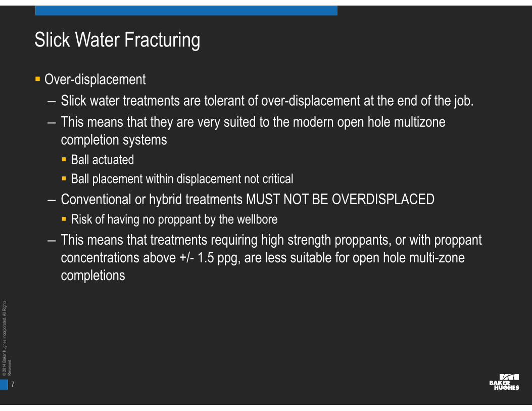
Slick Water Fracturing
Over-displacement
– Slick water treatments are tolerant of over-displacement at the end of the job.
– This means that they are very suited to the modern open hole multizonecompletion systems
Ball actuated
Ball placement within displacement not critical
– Conventional or hybrid treatments MUST NOT BE OVERDISPLACED
Risk of having no proppant by the wellbore
– This means that treatments requiring high strength proppants, or with proppantconcentrations above +/- 1.5 ppg, are less suitable for open hole multi-zonecompletions

8
©20
14B
aker
Hug
hes
Inco
rpor
ated
.All
Rig
hts
Res
erve
d.
])/[ln(
)(Pr
Srru
Pkhq
we
wfes
Siz
e,co
mp
lexi
ty,c
ost
oft
reat
men
tsin
crea
se
Short HighConductivity
Fractures
Longer LessConductiveFractures
Ultra-highSurface area
Fractures
Mobility, a Critical Driving ParameterWhat the reservoir needs
“Complex” Fractures
Planar Fractures
9
©20
14B
aker
Hug
hes
Inco
rpor
ated
.All
Rig
hts
Res
erve
d.
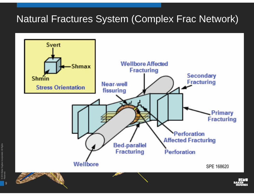
min
max
Natural Fractures System (Complex Frac Network)
SPE 168620

10
©20
14B
aker
Hug
hes
Inco
rpor
ated
.All
Rig
hts
Res
erve
d.
The Perfect Shale?
Slickwater fluids• Min. Sand Concentrations
• Simul, Zipper Fracs
Ductile-Anisotropic Shales• Hybrid fluids and or xlink fluids
• Biwing frac
Brittle
Isotropic
Ductile
Anisotropic
11
©20
14B
aker
Hug
hes
Inco
rpor
ated
.All
Rig
hts
Res
erve
d.
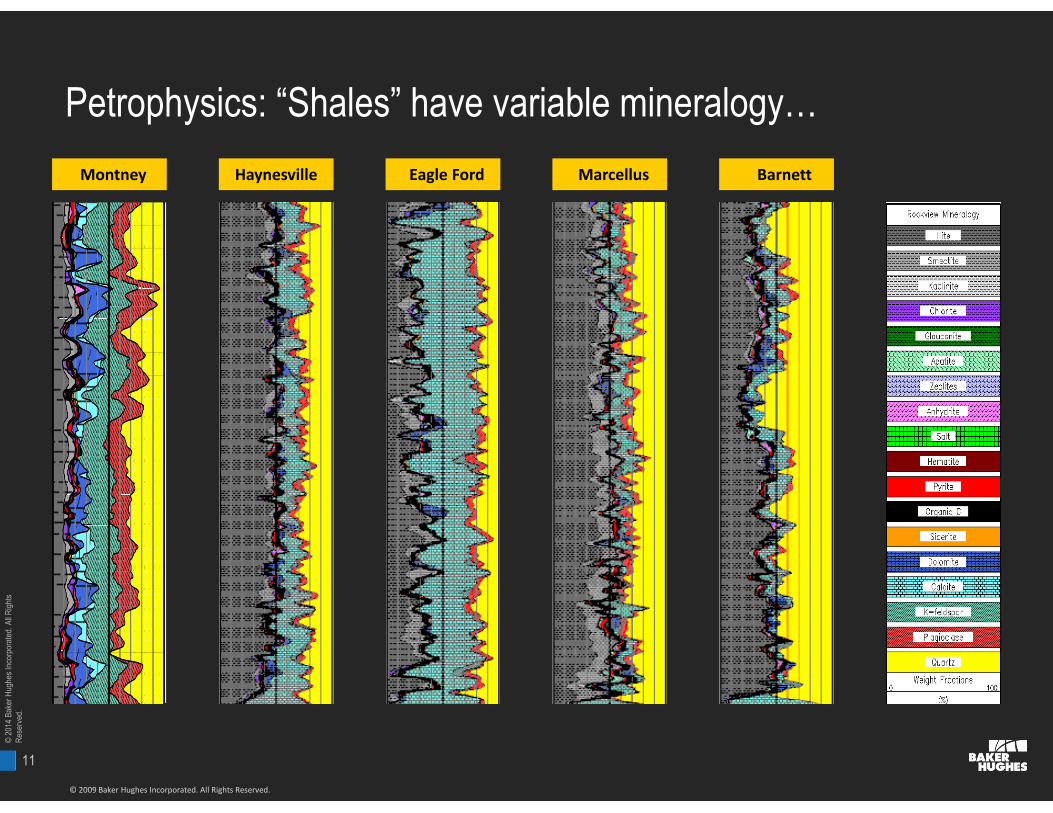
Petrophysics: “Shales” have variable mineralogy…
© 2009 Baker Hughes Incorporated. All Rights Reserved.
BarnettHaynesvilleMontney MarcellusEagle Ford

12
©20
14B
aker
Hug
hes
Inco
rpor
ated
.All
Rig
hts
Res
erve
d.©
2013
Bak
erH
ughe
sIn
corp
orat
ed.A
llR
ight
sR
eser
ved.
12
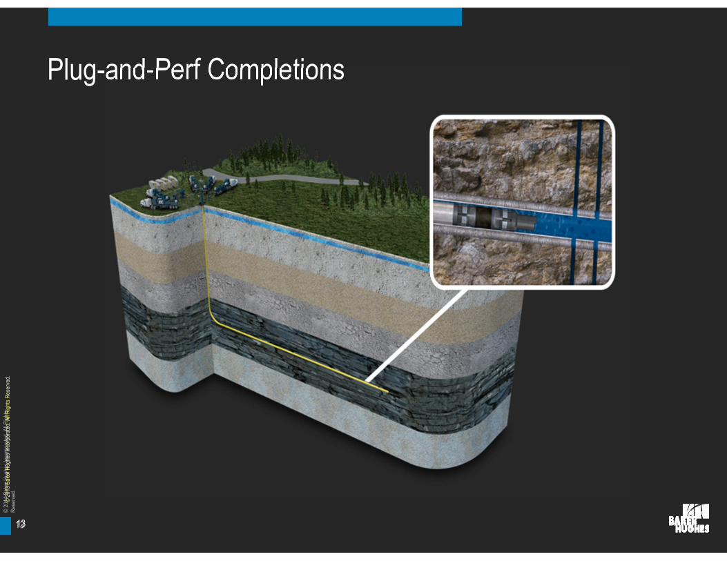
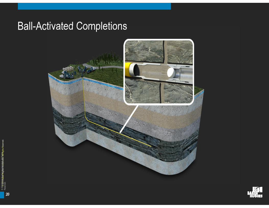
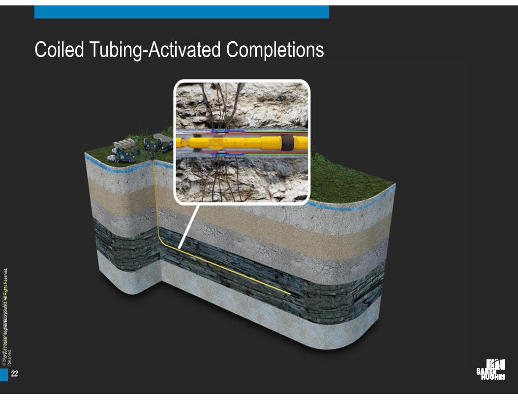
Plug-and-perf completion Ball-activated completion Coiled tubing-activatedcompletion
Which Completion?
13
©20
14B
aker
Hug
hes
Inco
rpor
ated
.All
Rig
hts
Res
erve
d.
Plug-and-Perf Completions
©20
13B
aker
Hug
hes
Inco
rpor
ated
.All
Rig
hts
Res
erve
d.
13
14
©20
14B
aker
Hug
hes
Inco
rpor
ated
.All
Rig
hts
Res
erve
d.
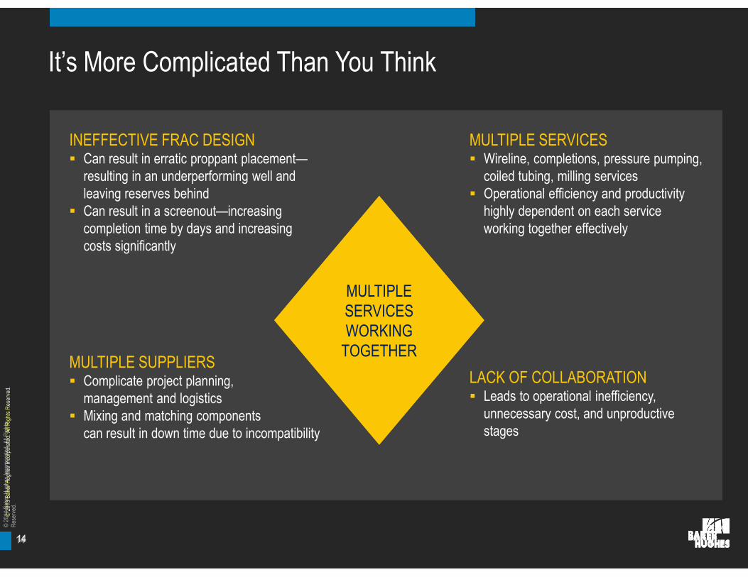
It’s More Complicated Than You Think
©20
13B
aker
Hug
hes
Inco
rpor
ated
.All
Rig
hts
Res
erve
d.
14
INEFFECTIVE FRAC DESIGN Can result in erratic proppant placement—
resulting in an underperforming well andleaving reserves behind
Can result in a screenout—increasingcompletion time by days and increasingcosts significantly
MULTIPLE SERVICES Wireline, completions, pressure pumping,
coiled tubing, milling services Operational efficiency and productivity
highly dependent on each serviceworking together effectively
MULTIPLE SUPPLIERS Complicate project planning,
management and logistics Mixing and matching components
can result in down time due to incompatibility
LACK OF COLLABORATION Leads to operational inefficiency,
unnecessary cost, and unproductivestages
MULTIPLESERVICESWORKING
TOGETHER
MULTIPLESERVICESWORKING
TOGETHER
15
©20
14B
aker
Hug
hes
Inco
rpor
ated
.All
Rig
hts
Res
erve
d.
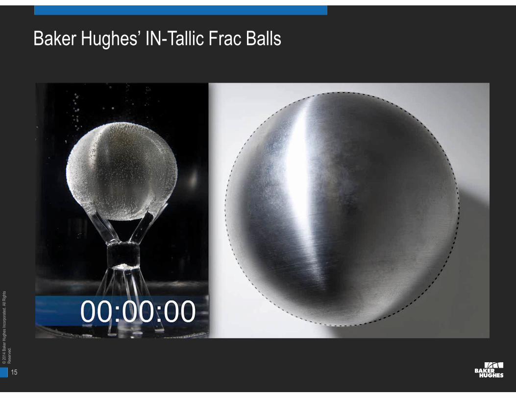
Baker Hughes’ IN-Tallic Frac Balls
16
©20
14B
aker
Hug
hes
Inco
rpor
ated
.All
Rig
hts
Res
erve
d.
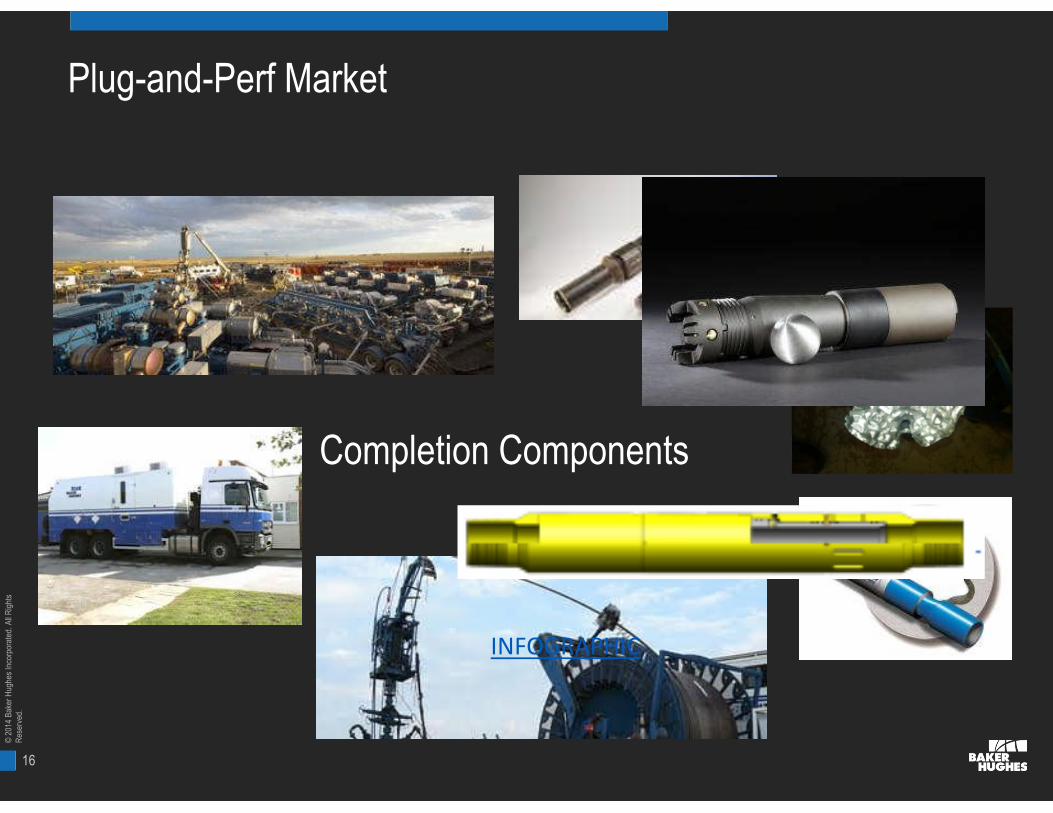
Plug-and-Perf Market
Completion Components
INFOGRAPHIC

17
©20
14B
aker
Hug
hes
Inco
rpor
ated
.All
Rig
hts
Res
erve
d.
Baker Hughes’ IN-Tallic Frac Balls

18
©20
14B
aker
Hug
hes
Inco
rpor
ated
.All
Rig
hts
Res
erve
d.
Shadow Plug Run History
■132 total runs
–59 in Canada
–73 in Marcellus/Utica
–5 Different Operators
–9 Different Wells
■Over 2,500 runs planned for2014 for 438 Shadow withthese 5 operators
■Furthest Plug Set
–MD 18,419’
–Horizontal Length 8,038’
–Planning 4.500” 11.60#field trials in 3-mile longlateral in Rockies
■Currently on 2 wells in theUtica area with 2 differentcustomers

19
©20
14B
aker
Hug
hes
Inco
rpor
ated
.All
Rig
hts
Res
erve
d.
Future Portfolio
Current Offering
5.5” 20.00 – 23.00 #/ft casing – 10,000 psi at 350F
Projects Started*
4.5” 11.60 – 13.50 #/ft casing – 10,000 psi at 350F – Ready Q2-14
4.5” 15.10 – 16.60 #/ft casing – 10,000 psi at 350F – Ready Q2-14
5.5” 23.00 – 26.00 #/ft casing – 10,000 psi at 350F – Ready Q3-14
Projects Upcoming*
5.50” 17.00 – 20.00 #/ft casing – 10,000 psi at 350F
5.00” 21.40 – 23.20 #/ft casing – 10,000 psi at 350F
5.50” 20.00 #/ft casing – 15,000 psi at 450F
5.00” 18.00 – 20.30 #/ft casing – 10,000 psi at 350F*All projects subject to change based on market demands
20
©20
14B
aker
Hug
hes
Inco
rpor
ated
.All
Rig
hts
Res
erve
d.
Ball-Activated Completions
©20
13B
aker
Hug
hes
Inco
rpor
ated
.All
Rig
hts
Res
erve
d.
20

21
©20
14B
aker
Hug
hes
Inco
rpor
ated
.All
Rig
hts
Res
erve
d.
Increase Efficiency and Performance In Long Laterals
©20
13B
aker
Hug
hes
Inco
rpor
ated
.All
Rig
hts
Res
erve
d.
21
NO THROUGH-TUBINGINTERVENTION Reduce risk by eliminating
through-tubing wireline orcoiled-tubing trip to fracturethe well
SIMPLIFIED LOGISTICS Pressure pumping is the
only service required on location
CONTINUOUS FRACTURING Eliminate down time between
stages for non-stop fracturing Reduce cycle time from
weeks to days
NO POST-FRAC MILLING REQUIRED Produce through ball seats and eliminate
post-frac milling requirements
FRACPOINT™MAXIMIZES
EFFICIENCY ANDPERFORMANCE
FRACPOINT™MAXIMIZES
EFFICIENCY ANDPERFORMANCE
22
©20
14B
aker
Hug
hes
Inco
rpor
ated
.All
Rig
hts
Res
erve
d.
Coiled Tubing-Activated Completions
©20
13B
aker
Hug
hes
Inco
rpor
ated
.All
Rig
hts
Res
erve
d.
22
23
©20
14B
aker
Hug
hes
Inco
rpor
ated
.All
Rig
hts
Res
erve
d.
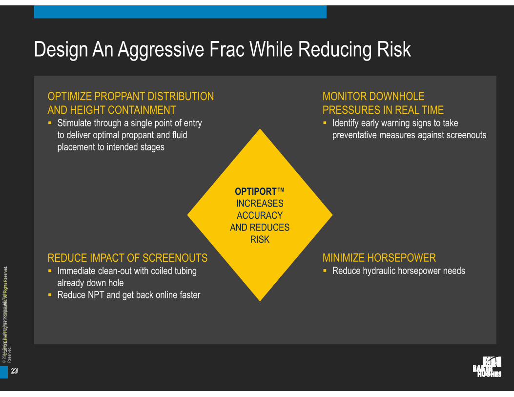
Design An Aggressive Frac While Reducing Risk
©20
13B
aker
Hug
hes
Inco
rpor
ated
.All
Rig
hts
Res
erve
d.
OPTIMIZE PROPPANT DISTRIBUTIONAND HEIGHT CONTAINMENT Stimulate through a single point of entry
to deliver optimal proppant and fluidplacement to intended stages
MONITOR DOWNHOLEPRESSURES IN REAL TIME Identify early warning signs to take
preventative measures against screenouts
REDUCE IMPACT OF SCREENOUTS Immediate clean-out with coiled tubing
already down hole Reduce NPT and get back online faster
MINIMIZE HORSEPOWER Reduce hydraulic horsepower needs
OPTIPORT™INCREASESACCURACY
AND REDUCESRISK
OPTIPORT™INCREASESACCURACY
AND REDUCESRISK
23
24
©20
14B
aker
Hug
hes
Inco
rpor
ated
.All
Rig
hts
Res
erve
d.
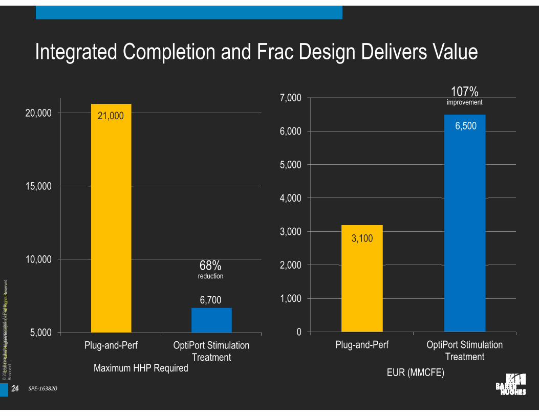
Integrated Completion and Frac Design Delivers Value
©20
13B
aker
Hug
hes
Inco
rpor
ated
.All
Rig
hts
Res
erve
d.
24
5,000
10,000
15,000
20,000
Plug-and-Perf OptiPort StimulationTreatment
Maximum HHP Required
68%reduction
6,700
21,000
0
1,000
2,000
3,000
4,000
5,000
6,000
7,000
Plug-and-Perf OptiPort StimulationTreatment
EUR (MMCFE)
6,500
3,100
107%improvement
SPE-163820
25
©20
14B
aker
Hug
hes
Inco
rpor
ated
.All
Rig
hts
Res
erve
d.
© 2014 BAKER HUGHES INCORPORATED. ALL RIGHTS RESERVED. TERMS AND CONDIT IONS OF USE: BY ACCEPTING THIS DOCUMENT, THE RECIPIENT AGREES THAT THE DOCUMENT TOGETHER W ITH ALL INFORMATION INCLUDED THEREIN IS THECONFIDENTIAL AND PROPRIETARY PROPERTY OF BAKER HUGHES INCORPORATED AND INCLUDES VALUABLE TRADE SECRETS AND/OR PROPRIETARY INFORMATION OF BAKER HUGHES ( COLLECTIVELY " INFORMATION") . BAKER HUGHES RETAINS ALL RIGHTSUNDER COPYRIGHT LAW S AND TRADE SECRET LAW S OF THE UNITED STATES OF AMERICA AND OTHER COUNTRIES. THE RECIPIENT FURTHER AGREES THAT THE DOCUMENT MAY NOT BE DISTRIBUTED, TRANSMITTED, COPIED OR REPRODUCED IN W HOLE ORIN PART BY ANY MEANS, ELECTRONIC, MECHANICAL , OR OTHERW ISE, W ITHOUT THE EXPRESS PRIOR W RITTEN CONSENT OF BAKER HUGHES, AND MAY NOT BE USED DIRECTLY OR INDIRECTLY IN ANY W AY DETRIMENTAL TO BAKER HUGHES’ INTEREST.
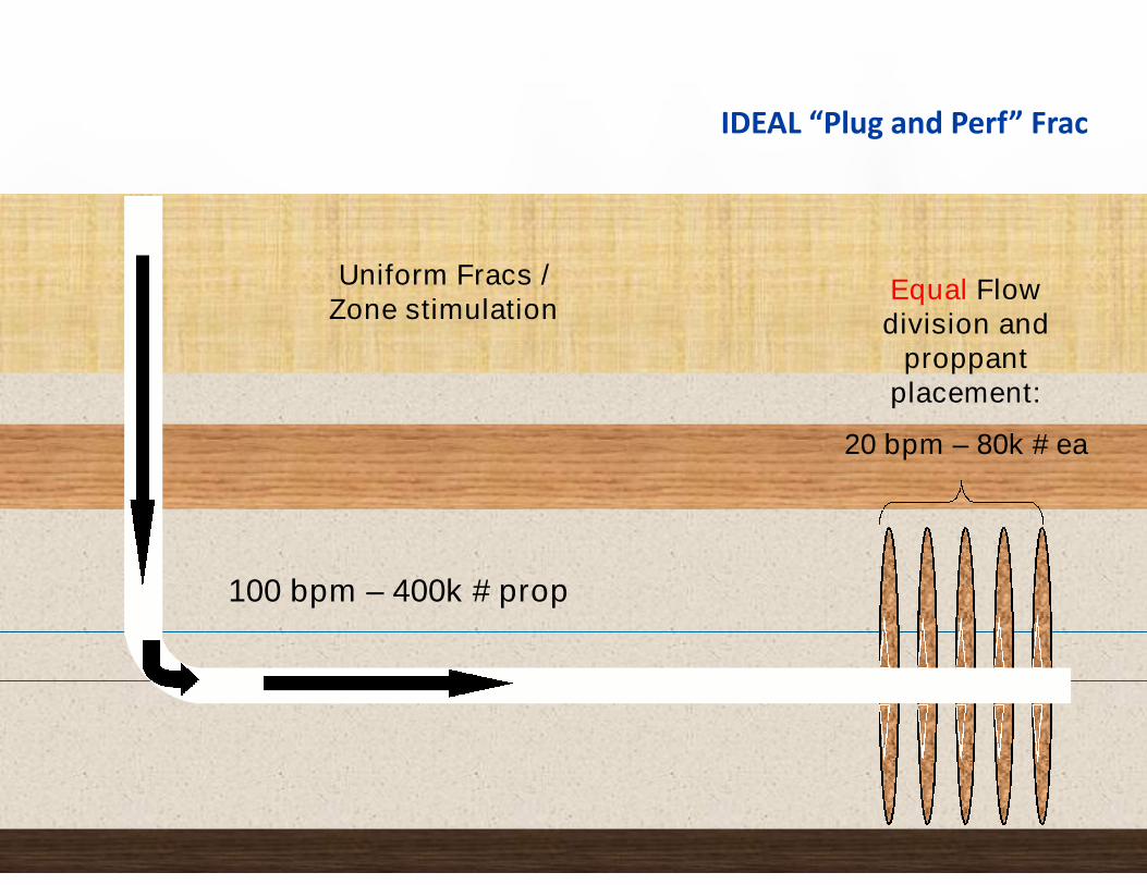
IDEAL “Plug and Perf” Frac
100 bpm – 400k # prop
Equal Flowdivision and
proppantplacement:
20 bpm – 80k # ea
Uniform Fracs /Zone stimulation
26
©20
14B
aker
Hug
hes
Inco
rpor
ated
.All
Rig
hts
Res
erve
d.
© 2014 BAKER HUGHES INCORPORATED. ALL RIGHTS RESERVED. TERMS AND CONDIT IONS OF USE: BY ACCEPTING THIS DOCUMENT, THE RECIPIENT AGREES THAT THE DOCUMENT TOGETHER W ITH ALL INFORMATION INCLUDED THEREIN IS THECONFIDENTIAL AND PROPRIETARY PROPERTY OF BAKER HUGHES INCORPORATED AND INCLUDES VALUABLE TRADE SECRETS AND/OR PROPRIETARY INFORMATION OF BAKER HUGHES ( COLLECTIVELY " INFORMATION") . BAKER HUGHES RETAINS ALL RIGHTSUNDER COPYRIGHT LAW S AND TRADE SECRET LAW S OF THE UNITED STATES OF AMERICA AND OTHER COUNTRIES. THE RECIPIENT FURTHER AGREES THAT THE DOCUMENT MAY NOT BE DISTRIBUTED, TRANSMITTED, COPIED OR REPRODUCED IN W HOLE ORIN PART BY ANY MEANS, ELECTRONIC, MECHANICAL , OR OTHERW ISE, W ITHOUT THE EXPRESS PRIOR W RITTEN CONSENT OF BAKER HUGHES, AND MAY NOT BE USED DIRECTLY OR INDIRECTLY IN ANY W AY DETRIMENTAL TO BAKER HUGHES’ INTEREST.
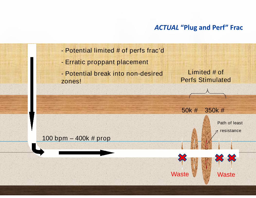
ACTUAL “Plug and Perf” Frac
100 bpm – 400k # prop
Limited # ofPerfs Stimulated
Waste Waste
- Potential limited # of perfs frac’d
- Erratic proppant placement
- Potential break into non-desiredzones!
50k # 350k #
Path of least
resistance
27
©20
14B
aker
Hug
hes
Inco
rpor
ated
.All
Rig
hts
Res
erve
d.
OptiPort™
■ Animation
28
©20
14B
aker
Hug
hes
Inco
rpor
ated
.All
Rig
hts
Res
erve
d.
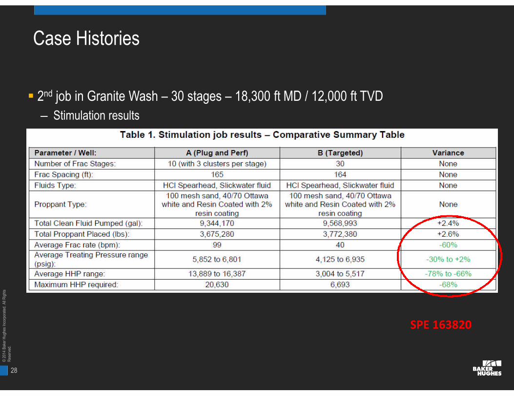
Case Histories
2nd job in Granite Wash – 30 stages – 18,300 ft MD / 12,000 ft TVD
– Stimulation results
SPE 163820

29
©20
14B
aker
Hug
hes
Inco
rpor
ated
.All
Rig
hts
Res
erve
d.
What to do?
Begin with the Hydraulic Fracturing in Mind!

30
©20
14B
aker
Hug
hes
Inco
rpor
ated
.All
Rig
hts
Res
erve
d.
Treatment Design Sample
17 propped fracture stages
2 Acid stages
3 Propped fracture designs (Alpha, Beta, Gamma)
80‘ cluster spacing = 63 perforated intervals
Monitor well
240 ft.320 ft.

31
©20
14B
aker
Hug
hes
Inco
rpor
ated
.All
Rig
hts
Res
erve
d.
Treatment Designs
DESIGN ALPHA BETA GAMMA
Fluid X-linked Tailored Slick
Gal/lb 0.7 1.09 1.66
Mlb/ Cluster 70 60 80
Bbl/cluster/min 18 20 25
Max conc., psa 6 2.5 1.5
% Pad * 38 29 58
70/140 mesh No No Yes
Sweeps No No Yes
Proppant 1 40/80 HydroProp 40/80 HydroProp 40/70 Sand
Proppant 2 30/50 EconoProp 30/50 EconoProp 40/80 HydroProp
Proppant 3 20/40 EconoProp ---- 30/50 EconoProp

32
©20
14B
aker
Hug
hes
Inco
rpor
ated
.All
Rig
hts
Res
erve
d.
We Know Everything about Fracs except,
The fracture half-length,
The fracture height,
The fracture orientation,
And
The fracture location once it leaves the wellbore

33
©20
14B
aker
Hug
hes
Inco
rpor
ated
.All
Rig
hts
Res
erve
d.
Down-hole Shale Well Monitoring Results
Dots show all events that were detected . Beachballs show focal mechanism calculated fromdownhole array.
34
©20
14B
aker
Hug
hes
Inco
rpor
ated
.All
Rig
hts
Res
erve
d.
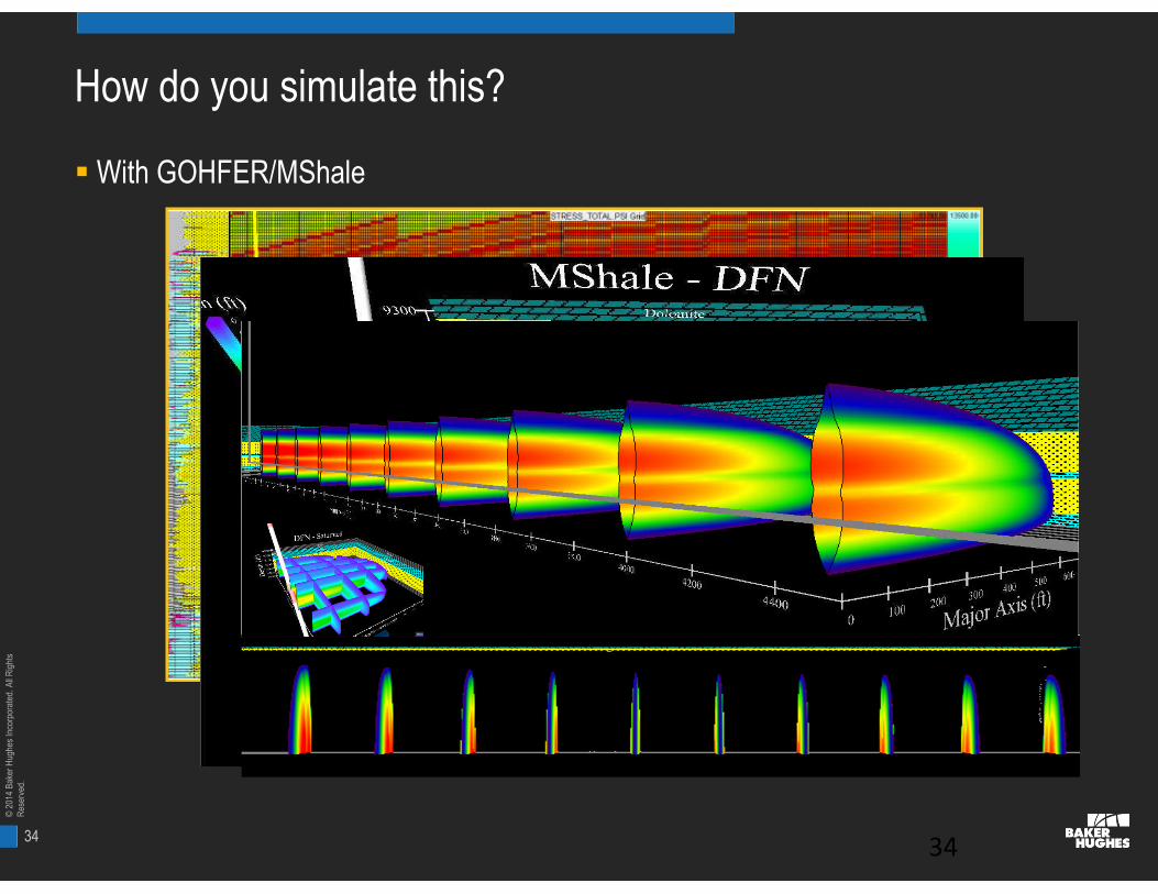
How do you simulate this?
With GOHFER/MShale
34

35
©20
14B
aker
Hug
hes
Inco
rpor
ated
.All
Rig
hts
Res
erve
d.
Magnitude: Integrated Science
Borehole & SurfaceMicroseismic Monitoring

36
©20
14B
aker
Hug
hes
Inco
rpor
ated
.All
Rig
hts
Res
erve
d.
Applications
• Real-time Engineering & Monitoring
• Fracture dimensions
• Screen outs
• Geohazard avoidance
• Thief zones
• Post-Job Analysis
• Characterizes far field response
• Fracture model calibration
• Reservoir/Geomechanical model calibration
Compared to the Frac job
• Energy represented by microseismicevents is infinitesimal
• Volume represented by microseismic eventdisplacements is very small
Introduction
37
©20
14B
aker
Hug
hes
Inco
rpor
ated
.All
Rig
hts
Res
erve
d.
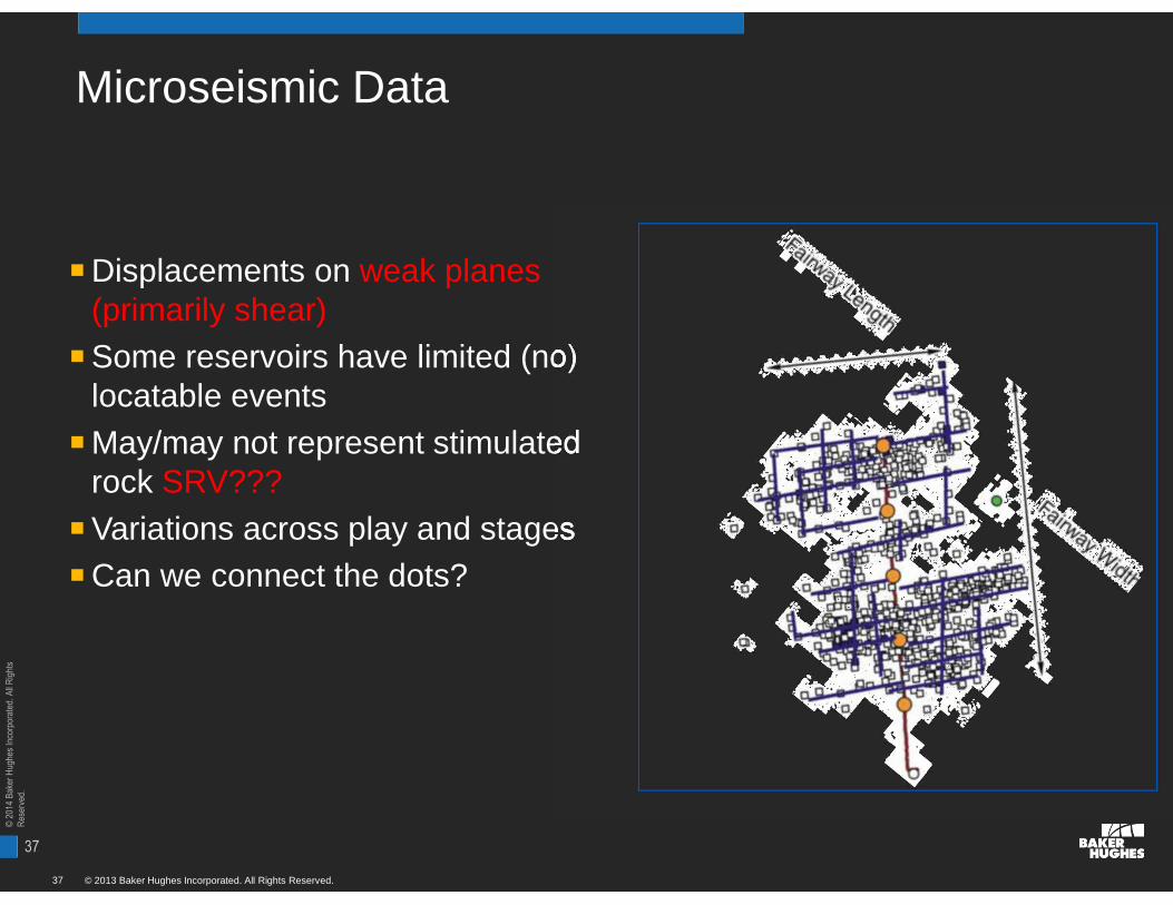
Microseismic Data
© 2013 Baker Hughes Incorporated. All Rights Reserved.37
■Displacements on weak planes(primarily shear)
■Some reservoirs have limited (no)locatable events
■May/may not represent stimulatedrock SRV???
■Variations across play and stages
■Can we connect the dots?

38
©20
14B
aker
Hug
hes
Inco
rpor
ated
.All
Rig
hts
Res
erve
d.
SRV or Microseismic Volume?
Began as drawing a rectilinear volume around the events to algorithms based onmagnitude of events.
Still it’s only a visual concept.
Production depends on:
– Frac surface area
– Connectivity
– Conductivity

39
©20
14B
aker
Hug
hes
Inco
rpor
ated
.All
Rig
hts
Res
erve
d.
Basic Microseismic Display
© 2013 Baker Hughes Incorporated. All Rights Reserved.39
40
©20
14B
aker
Hug
hes
Inco
rpor
ated
.All
Rig
hts
Res
erve
d.
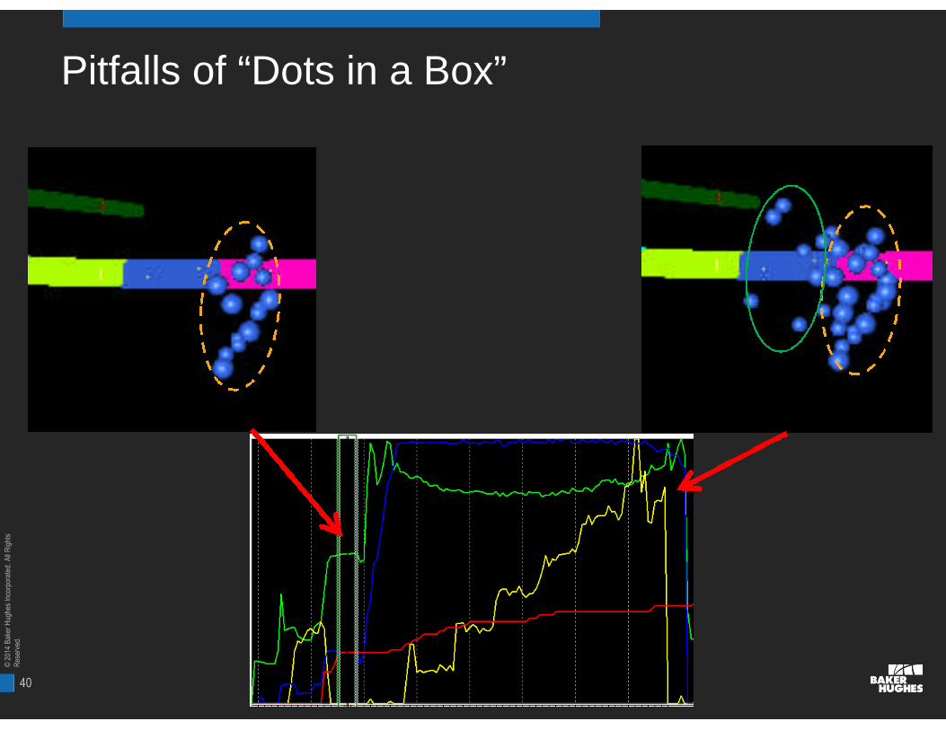
Pitfalls of “Dots in a Box”

41
©20
14B
aker
Hug
hes
Inco
rpor
ated
.All
Rig
hts
Res
erve
d.
Events Original vs “Cleaned”
Original Data
“Cleaned” Data
42
©20
14B
aker
Hug
hes
Inco
rpor
ated
.All
Rig
hts
Res
erve
d.
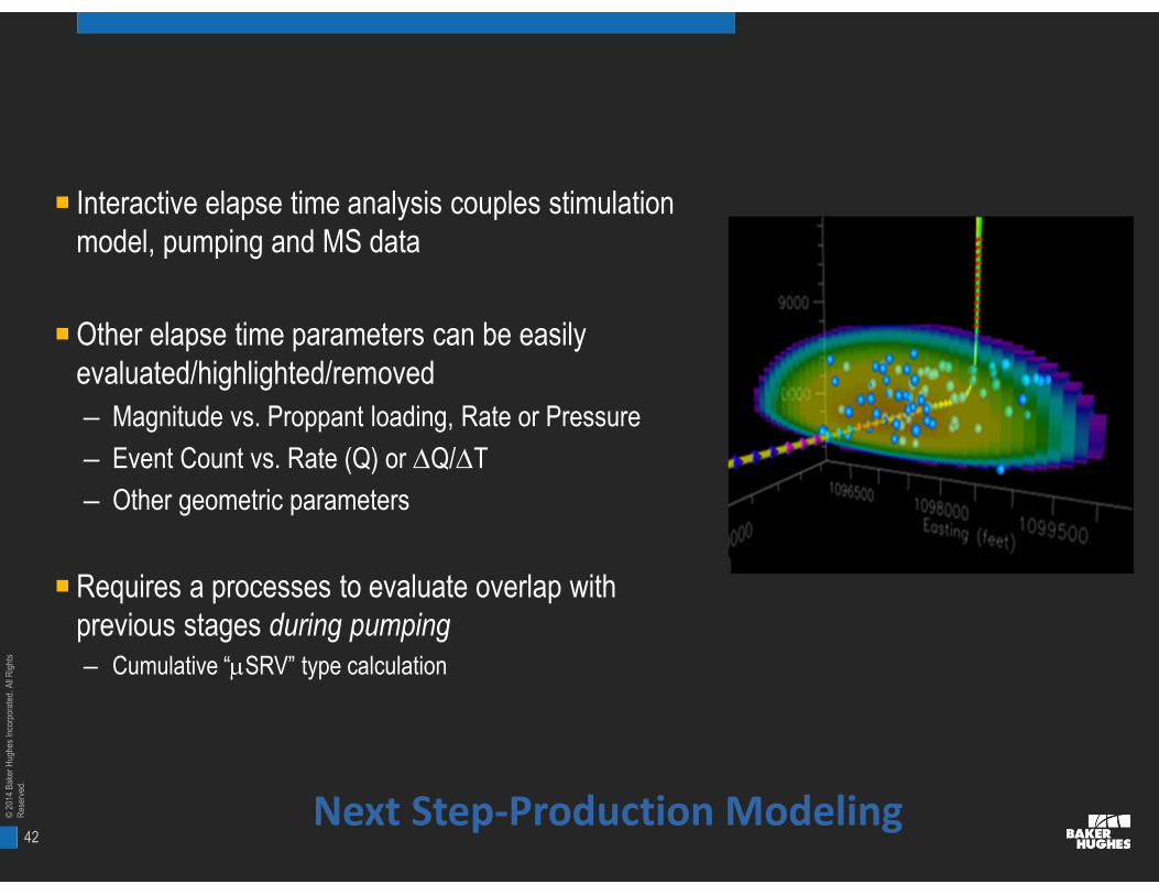
■ Interactive elapse time analysis couples stimulationmodel, pumping and MS data
■ Other elapse time parameters can be easilyevaluated/highlighted/removed
– Magnitude vs. Proppant loading, Rate or Pressure
– Event Count vs. Rate (Q) or DQ/DT
– Other geometric parameters
■ Requires a processes to evaluate overlap withprevious stages during pumping– Cumulative “mSRV” type calculation
Next Step-Production Modeling
43
©20
14B
aker
Hug
hes
Inco
rpor
ated
.All
Rig
hts
Res
erve
d.
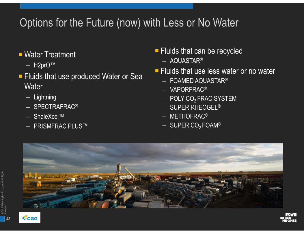
Options for the Future (now) with Less or No Water
■ Water Treatment– H2prO™
■ Fluids that use produced Water or SeaWater– Lightning
– SPECTRAFRAC®
– ShaleXcel™
– PRISMFRAC PLUS™
■ Fluids that can be recycled– AQUASTAR®
■ Fluids that use less water or no water– FOAMED AQUASTAR®
– VAPORFRAC®
– POLY CO2 FRAC SYSTEM
– SUPER RHEOGEL®
– METHOFRAC®
– SUPER CO2 FOAM®

44
©20
14B
aker
Hug
hes
Inco
rpor
ated
.All
Rig
hts
Res
erve
d.
Oilfield Water Management
Transforming a waste product into a resource
44 © 2012 Baker Hughes Incorporated. All Rights Reserved.
45
©20
14B
aker
Hug
hes
Inco
rpor
ated
.All
Rig
hts
Res
erve
d.
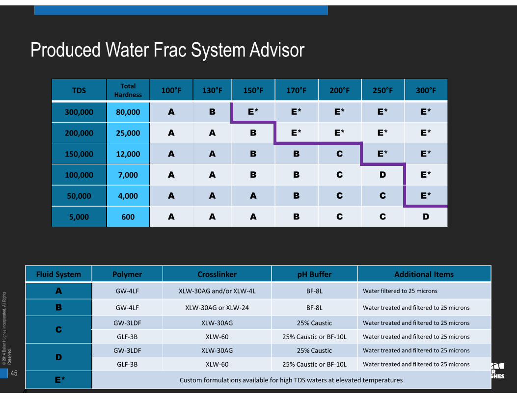
Produced Water Frac System Advisor
4
TDSTotal
Hardness100°F 130°F 150°F 170°F 200°F 250°F 300°F
300,000 80,000 A B E* E* E* E* E*
200,000 25,000 A A B E* E* E* E*
150,000 12,000 A A B B C E* E*
100,000 7,000 A A B B C D E*
50,000 4,000 A A A B C C E*
5,000 600 A A A B C C D
Fluid System Polymer Crosslinker pH Buffer Additional Items
A GW-4LF XLW-30AG and/or XLW-4L BF-8L Water filtered to 25 microns
B GW-4LF XLW-30AG or XLW-24 BF-8L Water treated and filtered to 25 microns
CGW-3LDF XLW-30AG 25% Caustic Water treated and filtered to 25 microns
GLF-3B XLW-60 25% Caustic or BF-10L Water treated and filtered to 25 microns
DGW-3LDF XLW-30AG 25% Caustic Water treated and filtered to 25 microns
GLF-3B XLW-60 25% Caustic or BF-10L Water treated and filtered to 25 microns
E* Custom formulations available for high TDS waters at elevated temperatures
46
©20
14B
aker
Hug
hes
Inco
rpor
ated
.All
Rig
hts
Res
erve
d.
■ Technology Overview
– Almost half of fracturing treatments areslick water
– High salinity (both TDS and hardness)detrimental to the polymer hydration
– Conventional friction reducers not ableto provide fast friction reduction oftenachieved in fresh water
– New friction reducer chemistrycompatible with high TDS and highhardness water
■ Technology Benefits
– Reduce the fresh water volume needed
– Eliminate cost associated with waterdisposal
– Reduce environmental footprint
– Effective friction reduction achieved
– Cost effective and operational friendly
4 © 2012 Baker Hughes
FRP-1 Friction Reducer for High TDSProduced Water
47
©20
14B
aker
Hug
hes
Inco
rpor
ated
.All
Rig
hts
Res
erve
d.
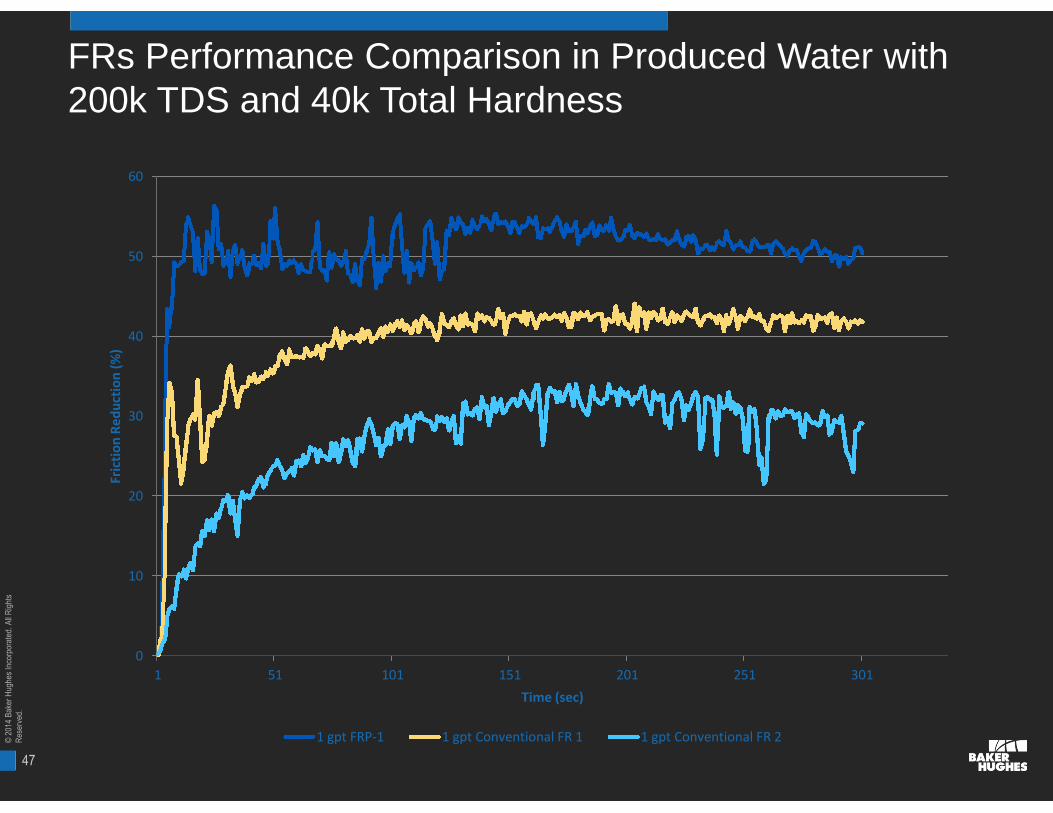
FRs Performance Comparison in Produced Water with200k TDS and 40k Total Hardness
0
10
20
30
40
50
60
1 51 101 151 201 251 301
Fric
tio
nR
ed
uct
ion
(%)
Time (sec)
1 gpt FRP-1 1 gpt Conventional FR 1 1 gpt Conventional FR 2

48
©20
14B
aker
Hug
hes
Inco
rpor
ated
.All
Rig
hts
Res
erve
d.
1
2
3
4
5
FR
P-1
(gp
t)
0
2000
4000
6000
8000
ST
P(p
si)
0
50
100
Cln
Rate
(bp
m)
0 100 200 300Elapsed Time (min)
FRP-1 Performance vs Conventional FR
1.5 gpt FRP-1at 57 bpm
STP=5770
1.5 gpt FRP-1at 60 bpmSTP=5270
1.0 gpt FRP-1 at60 bpm
STP=5880
2.0 gpt Conventional FR at 47bpm STP=7000 psi
Stages 14-17 Actual Pumping Results in 240k TDS and 50k Total HardnessWater at Hobbs, NM
49
©20
14B
aker
Hug
hes
Inco
rpor
ated
.All
Rig
hts
Res
erve
d.
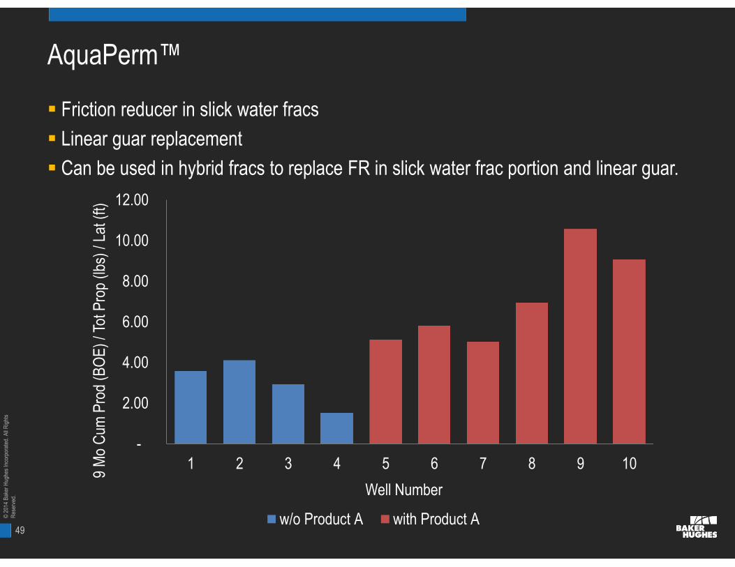
AquaPerm™
Friction reducer in slick water fracs
Linear guar replacement
Can be used in hybrid fracs to replace FR in slick water frac portion and linear guar.
-
2.00
4.00
6.00
8.00
10.00
12.00
1 2 3 4 5 6 7 8 9 10
9M
oC
umP
rod
(BO
E)/
TotP
rop
(lbs)
/Lat
(ft)
Well Number
w/o Product A with Product A
50
©20
14B
aker
Hug
hes
Inco
rpor
ated
.All
Rig
hts
Res
erve
d.
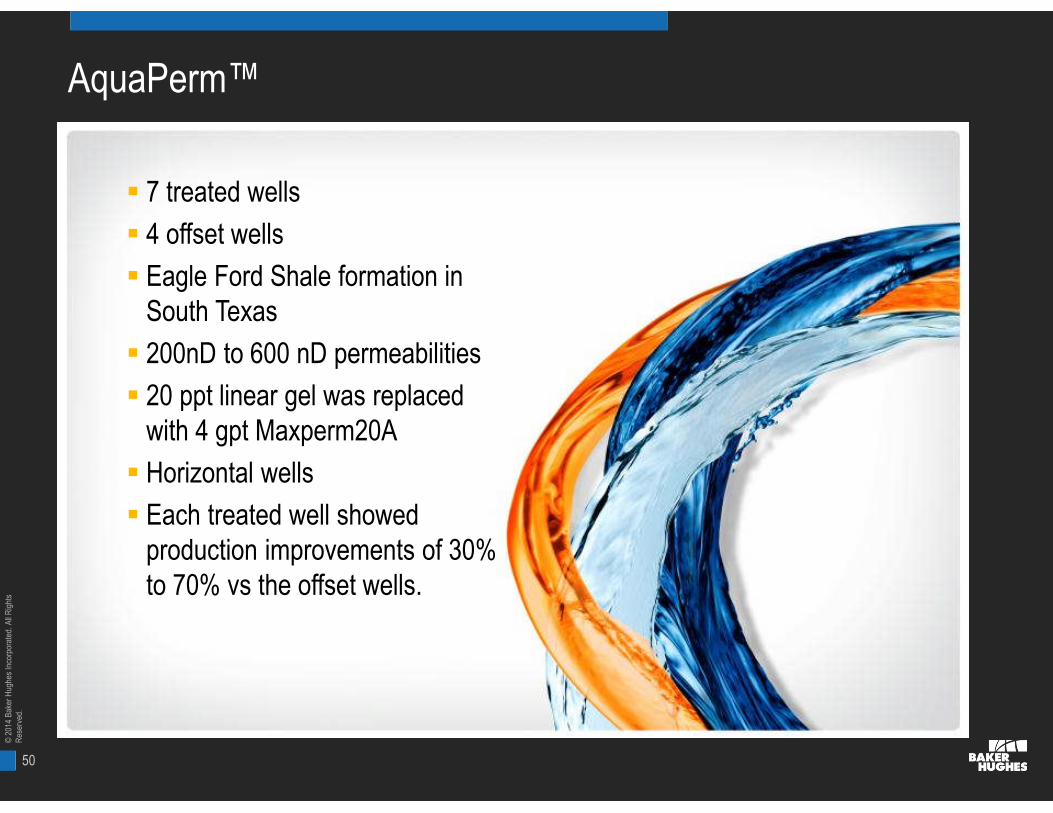
AquaPerm™
7 treated wells
4 offset wells
Eagle Ford Shale formation inSouth Texas
200nD to 600 nD permeabilities
20 ppt linear gel was replacedwith 4 gpt Maxperm20A
Horizontal wells
Each treated well showedproduction improvements of 30%to 70% vs the offset wells.
7 treated wells
4 offset wells
Eagle Ford Shale formation inSouth Texas
200nD to 600 nD permeabilities
20 ppt linear gel was replacedwith 4 gpt Maxperm20A
Horizontal wells
Each treated well showedproduction improvements of 30%to 70% vs the offset wells.
51
©20
14B
aker
Hug
hes
Inco
rpor
ated
.All
Rig
hts
Res
erve
d.
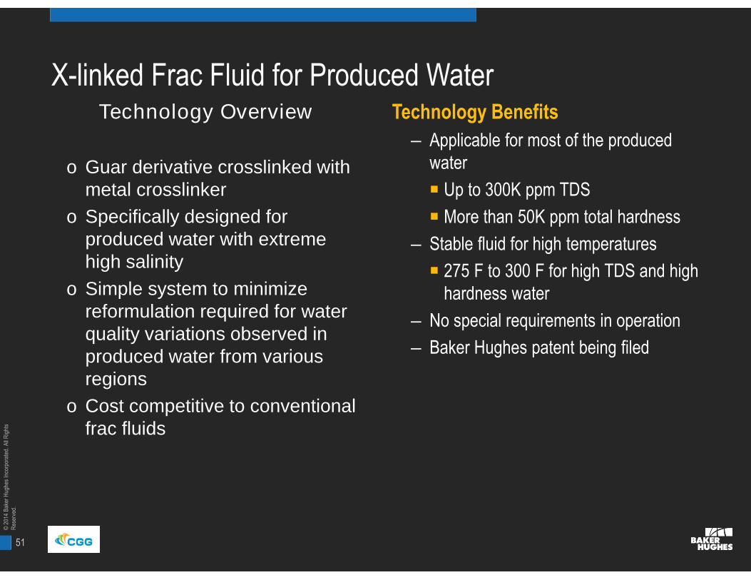
Technology Overview
o Guar derivative crosslinked withmetal crosslinker
o Specifically designed forproduced water with extremehigh salinity
o Simple system to minimizereformulation required for waterquality variations observed inproduced water from variousregions
o Cost competitive to conventionalfrac fluids
Technology Benefits
– Applicable for most of the producedwater
■ Up to 300K ppm TDS
■ More than 50K ppm total hardness
– Stable fluid for high temperatures
■ 275 F to 300 F for high TDS and highhardness water
– No special requirements in operation
– Baker Hughes patent being filed
X-linked Frac Fluid for Produced Water

52
©20
14B
aker
Hug
hes
Inco
rpor
ated
.All
Rig
hts
Res
erve
d.
USA Leads the World?
■ Normally, the USA Leads the FracturingWorld
– All new technologies and techniquesare tried in the US first, and thenspread to the Rest of the World
■ The One Exception to This isEnvironmental Compliance
– The USA is following EuropeUSA 75%
Canada10%
Rest of theWorld 15%
Global Fracturing Activity

53
©20
14B
aker
Hug
hes
Inco
rpor
ated
.All
Rig
hts
Res
erve
d.
Baker Hughes – Environmental Stewardship
Chemical Improvement
CEPR
SmartCareTM
Products and Systems
EnvironmentalServices Support
&
Regulatory
Reporting
Support
Equipment
Innovations
&
Water
Management
54
©20
14B
aker
Hug
hes
Inco
rpor
ated
.All
Rig
hts
Res
erve
d.
31 October 2011
Environmental Services Facilities
© 2009 Baker Hughes Incorporated. All Rights Reserved.54
U.S.A. ESG - Norway
55
©20
14B
aker
Hug
hes
Inco
rpor
ated
.All
Rig
hts
Res
erve
d.
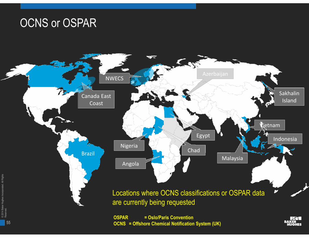
OCNS or OSPAR
Brazil
Nigeria
Angola
Chad
Egypt
Azerbaijan
Indonesia
Malaysia
Vietnam
SakhalinIsland
Canada EastCoast
NWECS
Locations where OCNS classifications or OSPAR dataare currently being requested
OSPAR = Oslo/Paris ConventionOCNS = Offshore Chemical Notification System (UK)
56
©20
14B
aker
Hug
hes
Inco
rpor
ated
.All
Rig
hts
Res
erve
d.
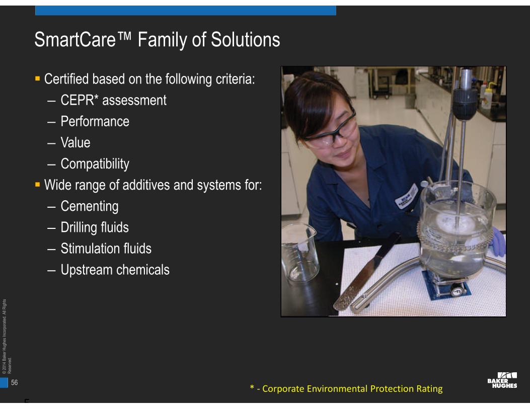
SmartCare™ Family of Solutions
Certified based on the following criteria:
– CEPR* assessment
– Performance
– Value
– Compatibility
Wide range of additives and systems for:
– Cementing
– Drilling fluids
– Stimulation fluids
– Upstream chemicals
5* - Corporate Environmental Protection Rating

57
©20
14B
aker
Hug
hes
Inco
rpor
ated
.All
Rig
hts
Res
erve
d.
SmartCare™ Designed To Have
Credibility in terms of the criteria and rationale used for the ranking
Transparency for easy explanation to stakeholders such as customers or regulators
Scientific Soundness, with a documented basis for criteria and ranking of eachhazard
Validity, based as much as possible on existing systems and criteria
Practicality, considering the range of chemicals used in well service products, theprofile of the suppliers and the data normally available for these chemicals
Quantitative to indicate relative “green-ness”
© 2013 Baker Hughes5
58
©20
14B
aker
Hug
hes
Inco
rpor
ated
.All
Rig
hts
Res
erve
d.
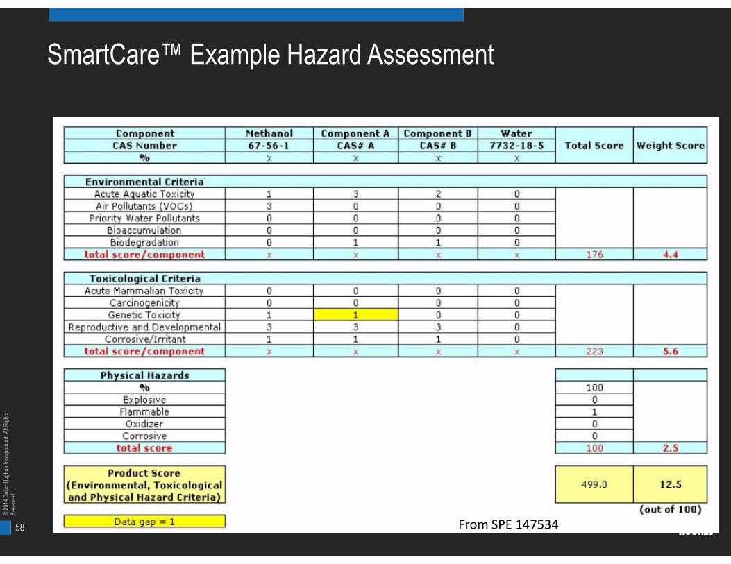
SmartCare™ Example Hazard Assessment
From SPE 147534
59
©20
14B
aker
Hug
hes
Inco
rpor
ated
.All
Rig
hts
Res
erve
d.
SmartCare™ Hazard Assessment
In a World Where Every Country, State and/or Region has Differing EnvironmentalCompliance Standards, the SmartCare™ Process Provides the Following Company-Wide Benefits
– Global assessment of environmental performance
– Criteria for continuous improvement
– Comparison of products with similar functionality
– Transparency and auditability
– Starting point for the introduction of new products into specific areas and/ormarkets
– Removal of products based on high Hazard Assessment score
5

60
©20
14B
aker
Hug
hes
Inco
rpor
ated
.All
Rig
hts
Res
erve
d.
Water Management in Shales
Most Shale wells produce Very little or No water (Exception – Antrim, a BiogenicShale)
However:
- Water may be produced later in well life or from fracturing into Water Zones
- With anticipated high numbers of shale wells, a small amount of water per well canadd up to large volumes
Water Problems are primarily associated with Frac Flowback Water (part ofComplete Water Cycle)
“Managing the Complete Water Cycle”

61
©20
14B
aker
Hug
hes
Inco
rpor
ated
.All
Rig
hts
Res
erve
d.
H2prO Water Management Service Treatment SolutionsBaker Hughes
61 © 2012 Baker Hughes Incorporated. All Rights Reserved.
62
©20
14B
aker
Hug
hes
Inco
rpor
ated
.All
Rig
hts
Res
erve
d.
Summary
Which fluid/completion/design? Which reservoir!?
Microseismic is part of the solution but needs acombination of all other parameters
Fracturing fluids are available to use any quality
water including produced waters or sea water
BHI has the necessary technology, expertise and
personnel to reduce risk, begin with the refrac in mind.
An integrated multi-disciplinary is key