
HF-520 seriesPower Transmission & Controls Group Headquarter ThinkPark Tower, 1-1 Osaki 2-chome,...
27
Power Transmission & Controls Group Headquarter ThinkPark Tower, 1-1 Osaki 2-chome, Shinagawa-ku, Tokyo 141-6025, Japan Specifications, dimensions, and other items are subject to change without prior notice. No.D2301E-1.2 EA04 Printed 2016.06 Worldwide Locations U.S.A Sumitomo Machinery Corporation of America (SMA) 4200 Holland Blvd. Chesapeake, VA 23323, U.S.A. TEL (1)757-485-3355 FAX (1)757-485-7490 Canada SM Cyclo of Canada, Ltd. (SMC) 1453 Cornwall Road, Oakville, Canada ON L6J 7T5 TEL (1)905-469-1050 FAX (1)905-469-1055 Mexico SM Cyclo de Mexico, S.A. de C.V. (SMME) Av. Desarrollo 541, Col. Finsa, Guadalupe, Nuevo León, México, CP67132 TEL (52)81-8144-5130 FAX (52)81-8144-5130 Brazil Sumitomo Industrias Pesadas do Brasil Ltda. (SHIB) Rodovia do Acucar (SP-075) Km 26 Itu, Sao Paulo, Brasil TEL (55)11-4886-1000 FAX (55)11-4886-1000 Chile SM-Cyclo de Chile Ltda. (SMCH) San Pablo 3507, Quinta Normal, Santiago, Chile TEL (56)2-892-7000 FAX (56)2-892-7001 Argentina SM-Cyclo de Argentina S.A. (SMAR) Ing. Delpini, 2236 Area de Promocion el Triangulo, Partido Malvinas Argentinas Grand Bourg, Buenos Aires, Argentina B1615KGB TEL (54)3327-45-4095 FAX (54)3327-45-4099 Guatemala SM Cyclo de Guatemala Ensambladora, Ltda. (SMGT) Parque Industrial Unisur, 0 Calle B 19-50 Zona 3, Bodega D-1 Delta Bárcenas en Villa Nueva, Guatemala TEL (502)6648-0500 FAX (502)6631-9171 Colombia SM Cyclo Colombia, S.A.S. (SMCO) Carrera 11, No.93A-53, Office 203, Bogotá, Colombia TEL (57)1-3000673 Germany Sumitomo (SHI) Cyclo Drive Germany GmbH (SCG) Cyclostraße 92, 85229 Markt Indersdorf, Germany TEL (49)8136-66-0 FAX (49)8136-5771 Austria Sumitomo (SHI) Cyclo Drive Germany GmbH (SCG) SCG Branch Austria Office Gruentalerstraße 30A, 4020 Linz, Austria TEL (43)732-330958 FAX (43)732-331978 Belgium Sumitomo (SHI) Cyclo Drive Germany GmbH (SCG) SCG Branch Benelux Office Heikneuterlaan 23, 3010 Kessel-Lo, Leuven, Belgium TEL (32)16-60-83-11 FAX (32)16-60-16-39 France SM-Cyclo France SAS (SMFR) 8 Avenue Christian Doppler, 77700 Serris, France TEL (33)164171717 FAX (33)164171718 Italy SM-Cyclo Italy Srl (SMIT) Via dell' Artigianato 23, 20010 Cornaredo (MI), Italy TEL (39)293-481101 FAX (39)293-481103 Spain SM-Cyclo Iberia, S.L.U. (SMIB) C/Landabarri No. 3, 6° B, 48940 Leioa, Vizcaya, Spain TEL (34)9448-05389 FAX (34)9448-01550 Sweden SM-Cyclo Scandinavia AB (SMSC) Industrigatan 21B, 234 35 Lomma, Sweden TEL (46)40220030 United Kingdom SM-Cyclo UK Ltd. (SMUK) Unit 29, Bergen Way, Sutton Fields Industrial Estate, Kingston upon Hull, HU7 0YQ, East Yorkshire, United Kingdom TEL (44)1482-790340 FAX (44)1482-790321 Turkey SM Cyclo Turkey Güç Aktarım Sis. Tic. Ltd. Sti. (SMTR) Büyükdere Çayırbaşı Cd. Dede Yusuf Sk. No: 11, 34453 Sarıyer Istanbul, Turkey TEL (90)216-384-4482 FAX (90)216-384-4482 China Sumitomo (SHI) Cyclo Drive China, Ltd. (SCT) 11F, SMEG Plaza, No. 1386 Hongqiao Road, Changning District, Shanghai, China (P.C. 200336) TEL (86)21-3462-7877 FAX (86)21-3462-7922 Hong Kong SM-Cyclo of Hong Kong Co., Ltd. (SMHK) Rm 1301, CEO Tower, 77 Wing Hong Street, Cheung Sha Wan, Kowloon, Hong Kong TEL (852)2460-1881 FAX (852)2460-1882 Korea Sumitomo (SHI) Cyclo Drive Korea, Ltd. (SCK) Royal Bldg. 9F Rm. 913, 5 Danju-Dong, Chongro-Ku, Seoul, Korea 110-721 TEL (82)2-730-0151 FAX (82)2-730-0156 Taiwan Tatung SM-Cyclo Co., Ltd. (TSC) 22 Chungshan N. Road 3rd., Sec. Taipei, Taiwan 104, R.O.C. TEL (886)2-2595-7275 FAX (886)2-2595-5594 Singapore Sumitomo (SHI) Cyclo Drive Asia Pacific Pte. Ltd. (SCA) 15 Kwong Min Road, Singapore 628718 TEL (65)6591-7800 FAX (65)6863-4238 Philippines Sumitomo (SHI) Cyclo Drive Asia Pacific Pte. Ltd. (SCA) Philippines Branch Office B2B Granville Industrial Complex, Carmona, Cavite 4116, Philippines TEL (63)2-584-4921 FAX (63)2-584-4922 TEL (63)46-430-3591 TEL (63)46-438-20579 - 81 Vietnam SM-Cyclo (Vietnam) Co., Ltd. (SMVN) Factory 2B, Lot K1-2-5, Road No. 2-3-5A, Le Minh Xuan Industrial Park, Binh Chanh Dist., HCMC, Vietnam TEL (84)8-3766-3709 FAX (84)8-3766-3710 Malaysia SM-Cyclo (Malaysia) Sdn. Bhd. (SMMA) No.7C, Jalan Anggerik Mokara 31/56, Kota Kemuning, Seksyen 31, 40460 Shah Alam, Selangor Darul Ehsan, Malaysia TEL (60)3-5121-0455 FAX (60)3-5121-0578 Indonesia PT. SM-Cyclo Indonesia (SMID) Jalan Sungkai Blok F 25 No. 09 K, Delta Silicon 5, Lippo Cikarang, Bekasi 17530, Indonesia TEL (62)21-2961-2100 FAX (62)21-2961-2211 Thailand SM-Cyclo (Thailand) Co., Ltd. (SMTH) 1 Empire Tower, Unit 2103-4, 21st Floor, South Sathorn Road, Yannawa, Sathorn, Bangkok 10120, Thailand TEL (66)2670-0998 FAX (66)2670-0999 Australia Sumitomo (SHI) Hansen Australia Pty. Ltd. (SHAU) 181 Power St, Glendenning, NSW 2761, Australia TEL (61)2-9208-3000 FAX (61)2-9208-3050 India Sumi-Cyclo Drive India Private Limited (SMIN) Survey No. 130, Hissa No. 02, Jeevan Nagar, Off Mumbai-Bangalore Bypass, Tathawade, Pune - 411033, India TEL (91)20-6674-2900 FAX (91)20-6674-2901 Japan Sumitomo Heavy Industries, Ltd. (SHI) ThinkPark Tower, 1-1 Osaki 2-chome, Shinagawa-ku, Tokyo 141-6025, Japan TEL (81)3-6737-2511 FAX (81)3-6866-5160 Sensorless Vector Inverter HF-520 series No.D2301E-1
Transcript of HF-520 seriesPower Transmission & Controls Group Headquarter ThinkPark Tower, 1-1 Osaki 2-chome,...

Power Transmission & Controls Group
Headquarter ThinkPark Tower, 1-1 Osaki 2-chome, Shinagawa-ku, Tokyo 141-6025, Japan
Specifications, dimensions, and other items are subject to change without prior notice.
No.D2301E-1.2EA04 Printed 2016.06
Worldwide Locations
U.S.ASumitomo Machinery Corporation of America (SMA)4200 Holland Blvd. Chesapeake, VA 23323, U.S.A.TEL (1)757-485-3355 FAX (1)757-485-7490
CanadaSM Cyclo of Canada, Ltd. (SMC)1453 Cornwall Road, Oakville, Canada ON L6J 7T5TEL (1)905-469-1050 FAX (1)905-469-1055
MexicoSM Cyclo de Mexico, S.A. de C.V. (SMME)Av. Desarrollo 541, Col. Finsa, Guadalupe,Nuevo León, México, CP67132TEL (52)81-8144-5130 FAX (52)81-8144-5130
BrazilSumitomo Industrias Pesadas do Brasil Ltda. (SHIB)Rodovia do Acucar (SP-075) Km 26Itu, Sao Paulo, Brasil TEL (55)11-4886-1000 FAX (55)11-4886-1000
ChileSM-Cyclo de Chile Ltda. (SMCH)San Pablo 3507, Quinta Normal, Santiago, ChileTEL (56)2-892-7000 FAX (56)2-892-7001
ArgentinaSM-Cyclo de Argentina S.A. (SMAR)Ing. Delpini, 2236 Area de Promocion el Triangulo,Partido Malvinas Argentinas Grand Bourg,Buenos Aires, Argentina B1615KGBTEL (54)3327-45-4095 FAX (54)3327-45-4099
GuatemalaSM Cyclo de Guatemala Ensambladora, Ltda. (SMGT)Parque Industrial Unisur, 0 Calle B 19-50 Zona 3,Bodega D-1 Delta Bárcenas en Villa Nueva, GuatemalaTEL (502)6648-0500 FAX (502)6631-9171
ColombiaSM Cyclo Colombia, S.A.S. (SMCO)Carrera 11, No.93A-53, Office 203, Bogotá, ColombiaTEL (57)1-3000673
GermanySumitomo (SHI) Cyclo Drive Germany GmbH (SCG)Cyclostraße 92, 85229 Markt Indersdorf, GermanyTEL (49)8136-66-0 FAX (49)8136-5771
AustriaSumitomo (SHI) Cyclo Drive Germany GmbH (SCG)SCG Branch Austria OfficeGruentalerstraße 30A, 4020 Linz, AustriaTEL (43)732-330958 FAX (43)732-331978
BelgiumSumitomo (SHI) Cyclo Drive Germany GmbH (SCG)SCG Branch Benelux OfficeHeikneuterlaan 23, 3010 Kessel-Lo, Leuven, BelgiumTEL (32)16-60-83-11 FAX (32)16-60-16-39
FranceSM-Cyclo France SAS (SMFR)8 Avenue Christian Doppler, 77700 Serris, FranceTEL (33)164171717 FAX (33)164171718
ItalySM-Cyclo Italy Srl (SMIT)Via dell' Artigianato 23, 20010 Cornaredo (MI), ItalyTEL (39)293-481101 FAX (39)293-481103
SpainSM-Cyclo Iberia, S.L.U. (SMIB)C/Landabarri No. 3, 6° B, 48940 Leioa, Vizcaya, SpainTEL (34)9448-05389 FAX (34)9448-01550
SwedenSM-Cyclo Scandinavia AB (SMSC)Industrigatan 21B, 234 35 Lomma, SwedenTEL (46)40220030
United KingdomSM-Cyclo UK Ltd. (SMUK)Unit 29, Bergen Way, Sutton Fields Industrial Estate, Kingston upon Hull, HU7 0YQ, East Yorkshire, United KingdomTEL (44)1482-790340 FAX (44)1482-790321
TurkeySM Cyclo Turkey Güç Aktarım Sis. Tic. Ltd. Sti. (SMTR)Büyükdere Çayırbaşı Cd. Dede Yusuf Sk. No: 11,34453 Sarıyer Istanbul, Turkey TEL (90)216-384-4482 FAX (90)216-384-4482
ChinaSumitomo (SHI) Cyclo Drive China, Ltd. (SCT) 11F, SMEG Plaza, No. 1386 Hongqiao Road,Changning District, Shanghai, China (P.C. 200336)TEL (86)21-3462-7877 FAX (86)21-3462-7922
Hong KongSM-Cyclo of Hong Kong Co., Ltd. (SMHK)Rm 1301, CEO Tower, 77 Wing Hong Street,Cheung Sha Wan, Kowloon, Hong Kong TEL (852)2460-1881 FAX (852)2460-1882
KoreaSumitomo (SHI) Cyclo Drive Korea, Ltd. (SCK)Royal Bldg. 9F Rm. 913, 5 Danju-Dong, Chongro-Ku,Seoul, Korea 110-721 TEL (82)2-730-0151 FAX (82)2-730-0156
TaiwanTatung SM-Cyclo Co., Ltd. (TSC)22 Chungshan N. Road 3rd., Sec. Taipei, Taiwan 104, R.O.C.TEL (886)2-2595-7275 FAX (886)2-2595-5594
SingaporeSumitomo (SHI) Cyclo Drive Asia Pacific Pte. Ltd. (SCA)15 Kwong Min Road, Singapore 628718TEL (65)6591-7800 FAX (65)6863-4238
PhilippinesSumitomo (SHI) Cyclo Drive Asia Pacific Pte. Ltd. (SCA)Philippines Branch OfficeB2B Granville Industrial Complex, Carmona,Cavite 4116, PhilippinesTEL (63)2-584-4921 FAX (63)2-584-4922TEL (63)46-430-3591TEL (63)46-438-20579 - 81
VietnamSM-Cyclo (Vietnam) Co., Ltd. (SMVN)Factory 2B, Lot K1-2-5, Road No. 2-3-5A,Le Minh Xuan Industrial Park, Binh Chanh Dist.,HCMC, VietnamTEL (84)8-3766-3709 FAX (84)8-3766-3710
MalaysiaSM-Cyclo (Malaysia) Sdn. Bhd. (SMMA)No.7C, Jalan Anggerik Mokara 31/56, Kota Kemuning,Seksyen 31, 40460 Shah Alam, Selangor Darul Ehsan, MalaysiaTEL (60)3-5121-0455 FAX (60)3-5121-0578
IndonesiaPT. SM-Cyclo Indonesia (SMID)Jalan Sungkai Blok F 25 No. 09 K, Delta Silicon 5, Lippo Cikarang, Bekasi 17530, IndonesiaTEL (62)21-2961-2100 FAX (62)21-2961-2211
ThailandSM-Cyclo (Thailand) Co., Ltd. (SMTH)1 Empire Tower, Unit 2103-4, 21st Floor, South Sathorn Road, Yannawa, Sathorn, Bangkok 10120, ThailandTEL (66)2670-0998 FAX (66)2670-0999
AustraliaSumitomo (SHI) Hansen Australia Pty. Ltd. (SHAU)181 Power St, Glendenning, NSW 2761, AustraliaTEL (61)2-9208-3000 FAX (61)2-9208-3050
IndiaSumi-Cyclo Drive India Private Limited (SMIN)Survey No. 130, Hissa No. 02, Jeevan Nagar, Off Mumbai-Bangalore Bypass, Tathawade, Pune - 411033, IndiaTEL (91)20-6674-2900 FAX (91)20-6674-2901
JapanSumitomo Heavy Industries, Ltd. (SHI)ThinkPark Tower, 1-1 Osaki 2-chome, Shinagawa-ku,Tokyo 141-6025, JapanTEL (81)3-6737-2511 FAX (81)3-6866-5160
Sensorless Vector Inverter
HF-520 series
No.D2301E-1

1
HF-520 series : The user friendly Sensorless Vector
Control Drive!
Powerful Inverter suitable for SUMITOMO Gearmotor
Sensorless vector control allows for high starting torque.
Deceleration time can be shortened by the overexcitation operation of braking
function.
This inverter is ideal for SUMITOMO Gearmotor operation.
Easy Parameter Setting for the Application
The most suitable parameters are pre-set automatically by choosing the type of
applications such as conveyor, lifter and etc.
This will help to reduce testing and commissioning time.
Easy Parameter Management
A copy of the parameter values settings by the LED operator can be used to
transfer to other inverters.
Parameter setting file can be managed using Engineering Tool for PC.
Long Lifetime Inverter
The capacitor and cooling fan are designed for long lifetime operation (10 years).
Maintenance time can be checked by LED operator.
Corresponds to major standards of the world
< Table of Contents >Explanation of Functions ……………………… 1~2
Operation …………………………………… 3~4
Standard and Common Specifications ………… 5
Standerd Connection Diagram ………………… 6
Terminal Functions …………………………… 7
Applied Connection Diagram ………………… 8
Table of Parameters ………………………… 9~12
Outline Drawing ……………………………… 13

2
Power Range
Voltage Class(Input/Rated output)
Applicable Motor (kW)
0.2 0.4 0.75 1.5 2.2 3.7 5.5 7.5
3-phase 200V/3-phase 200V
3-phase 400V/3-phase 400V
1-phase 200V/3-phase 200V
Model No.
Gearmotor Product Lineup
CYCLO® HYPONIC Gearmotor® PREST® NEO Gearmotor
HF520 : HF-520 series
Power supply 2 : 3-phase 200V 4 : 3-phase 400V S : 1-phase 200V
HF520 2 − A20
Output power A20 : 0.2kW 1A5 : 1.5kW 5A5 : 5.5kW A40 : 0.4kW 2A2 : 2.2kW 7A5 : 7.5kW A75 : 0.75kW 3A7 : 3.7kW
HF-520 series
Bevel BUDDYBOX® and Helical BUDDYBOX® which can be driven by HF-520 too.
Applicable Wiring for Accessories and Options … 14
Peripheral Equipment ………………………… 15
External Options …………………………… 16~21
Notes to Inverter Users ……………………… 22~24
Selection Guide ……………………………… 25
Warranty …………………………………… 26

3
Operation
LED On Flashing Off
LED Display
STOP KeyStop the drive.
LED Display
REV
FOUT
DRV
ALM
ENTER KeySelect all modes, parameters, settings, etc.Select a menu item to move from one display screen to the next.
Data Display Area(5-digit)Displays frequency, parameter number, and other data.
LO/RE Lamp Light to indicate that the operator is set to LOCAL.
ESC Key Return to the previous menu.
Easy OperationUsed as a quick guide for the abbreviations used on the display screen.
RESET & SHIFT KeyResets to clear a fault situation.Move the cursor to the right.
RUN LampLight while the drive is operating the motor.
RUN KeyStart the drive.
Communication PortPort used for LED Operator.
Up KeyScroll up to select parameter numbers, setting values, etc.
Down KeyScroll down to select parameter numbers, setting values, etc.
LO/RE Selection KeySwitch drive control between the operator (LOCAL) andthe control terminals (REMOTE).
When the inverter detect the alarm
• When an alarm occurs• OPE (Operation Error) detected• When a fault or error occurs during Auto-Tuning
• During deceleration to stop• When the Run command is input and the frequency reference is 0.
Motor is rotating in reverse Drive Mode.
• Drive Mode• Auto-Tuning
Display output frequency (Hz)
When the Run command is selected fromthe LED operator (LOCAL).
During run
Normal state
Motor Forward rotation
Programming mode
Display except output frequency
Other than LED operator(REMOTE)
During stop
4
Operation
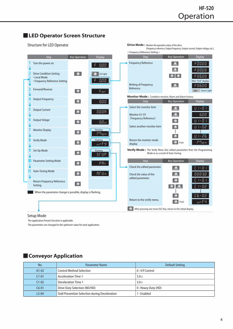
LED Operator Screen Structure
Conveyor Application
No. Parameter Name Default Setting
A1-02 Control Method Selection 0 : V/f Control
C1-01 Acceleration Time 1 3.0 s
C1-02 Deceleration Time 1 3.0 s
C6-01 Drive Duty Selection (ND/HD) 0 : Heavy Duty (HD)
L3-04 Stall Prevention Selection during Deceleration 1 : Enabled
1
2
3
4
DRV
5
6
7
8
9
10
11
Tum the power on
Drive Condition Setting• Local Mode• Frequency Reference Setting
Forward/Reverse
Output Frequency
Output Current
Output Volage
Monitor Display
Verify Mode
Set Up Mode
Parameter Setting Mode
Auto-Tuning Mode
Return Frequency Reference Setting
Flashing
Flashing
Flashing
When the parameter change is possible, display is flashing.
Step DisplayKey Operation Step DisplayKey Operation
Step DisplayKey Operation
Step DisplayKey Operation
< Frequency Reference Setting >
Frequency Reference
Writing of Frequency Reference
After “End” display
Green Light
Monitor Mode : Condition monitor, Alarm and Alarm history
Select the monitor item
Monitor U1-O1(Frequency Reference)
Select another monitor item
Push
Push
Verify Mode :
Check the edited parameter.
Check the value of the edited parameter.
LO Light
Return to the verify menu.
After pressing one more ESC Key, return to the initial display.
The Verify Menu lists edited parameters from the Programming Mode or as a result of Auto-Tuning.
Drive Mode : Structure for LED Operator Monitor the operation status of the drive(Frequency reference, Output frequency, Output current, Output voltage, etc.).
Return the monitor mode display
The application Presets function is applicable.
The parameters are changed to the optimum value for each application.
Setup Mode

5
Standard and Common Specifications
Standard SpecificationsItem Specifications
Input Voltage Class 3-phase 200V / 3-phase 400V / 1-phase 200V
Applicable Motor (kW) 0.2 0.4 0.75 1.5 2.2 3.7 5.5 7.5
Ratin
g
Input Voltage Class Model No. HF520 -
3-phase 200V HF5202-A20 A40 A75 1A5 2A2 3A7 5A5 7A53-phase 400V HF5204-
1-phase 200V HF520S- - - -
Rated Output Capacity (kVA)200V class 0.6 1.1 1.9 3.0 4.2 6.7 9.5 12.6
400V class 0.9 1.4 2.6 3.7 4.2 7.0 11.3 13.7
Rated Output Capacity (A)
3-phase 200V input 1.6 3.0 5.0 8.0 11.0 17.5 25.0 33.0
3-phase 400V input 1.2 1.8 3.4 4.8 5.5 9.2 14.8 18.0
1-phase 200V input 1.6 3.0 5.0 8.0 11.0 - - -
Output Voltage 3-phase 200V~240V (200V class) / 3-phase 380~480V (400V class)
Over Load Current Rating 150% 1 minute
Pow
er S
uppl
y
Voltage Frequency
3-phase 200V 3-phase 200V~240V 50/60Hz
3-phase 400V 3-phase 380V~480V 50/60Hz
1-phase 200V 1-phase 200V~240V 50/60Hz
Allowable Fluctuation Voltage -15~+10%, Frequency±5%
Protective Method Enclosed Type IP20 Enclosed Type (NEMA Type1)
Cooling Method
3-phase 200V Self-cooling Cooling fan
3-phase 400V Self-cooling Cooling fan
1-phase 200V Self-cooling Cooling fan -
Common SpecificationsItem Specifications
Cont
rol C
hara
cter
istic
s
Control Method Sensorless Vector Control , V/f ControlFrequency Control Range 0.01 to 400 Hz
Frequency AccuracyDigital input: within ±0.01% of the max output frequency (-10 to +50 °C)Analog input: within ±0.5% of the max output frequency (25 °C ±10 °C)
Frequency Setting ResolutionDigital inputs: 0.01 HzAnalog inputs: 1/1000 of maximum output frequency
Output Frequency CalculationResolution 1/220 x Maximum output frequency (E1-04)
Frequency Setting Signal Main frequency reference: 0 to +10 Vdc (20 kΩ), 4 to 20 mA (250 Ω),0 to 20 mA (250 Ω)Main speed reference: Pulse Train Input (max 32 kHz)
Torque Limit Sensorless Vector Control only. Adjustable in 4 quadrants.Accel/Decel Time 0.00 to 6000.0 s (allows four separate settings for accel and decel)
Braking Torque Instantaneous Average Decel Torque <2> : 0.1/0.2 kW: over 150%, 0.4/0.75 kW: over 100%, 1.5 kW: over 50%, 2.2 kW and above: over 20% Continuous Regen Torque: 20%, 125% with a Braking Resistor Unit <3> : (10% ED) 10 s with an internal braking resistor.
V/f Characteristics Preset V/f patterns and user-set program available.
Functions
Momentary Power Loss Ride-Thru,Speed Search Over/Undertorque Detection,Torque Limit, Multi-Step Speed (17 steps max) Accel/Decel Time Switch,S-Curve Accel/Decel,2-Wire/3-Wire Sequence,Rotational Auto-Tuning Stationary Auto-Tuning of Line-to-Line Resistance,Dwell,Cooling Fan ON/OFF,Slip Compensation Torque Compensation,Jump Frequencies (reference dead band) Frequency Reference Upper/Lower Limit,DC Injection Braking (start and stop), High Slip Braking PID Control (with Sleep Function),Energy Saving,MEMOBUS/Modbus (RS-485/RS-422) Fault Reset,Parameter Copy,Fault Restart,Removable Terminals with Parameter Backup Function
Carrier Frequency 5 kHz (user-adjustable from 2 to 15 kHz)
Prot
ectio
n Fu
nctio
ns
Motor Protection Motor overheat protection via output current sensorOvercurrent Protection Drives stops when output exceeds 200% of the rated currentOverload Protection A stop command will be entered after operating at 150% for 60 s
Overvoltage Specification200 V Class: Stops when DC bus voltage exceeds approx. 410 V400 V Class: Stops when DC bus voltage exceeds approx. 820 V
Low Voltage ProtectionDrive stops when DC bus voltage falls below the levels indicated: <5>190 V (3-phase 200 V), 160 V (single-phase 200 V)380 V (3-phase 400 V), 350 V (3-phase 380 V)
Momentary Power LossRide-Thru
3 selections available: Ride-Thru disabled (stops after 15 ms), time base of 0.5 s, and continue running as long as the drive control board is powered up.
Heatsink Overheat Protection Protected by thermistor
Stall Prevention Stall prevention is available during acceleration, deceleration, and duringrun. Separate settingsfor each type of stall prevention determine the current level at which stall prevention is triggered
Ground Fault Protection Electronic circuit protectionDC Bus Charge LED Remains lit until DC bus voltage falls below 50 V
Envi
ronm
ent
Storage/Installation Area Indoors
Ambient Temperature IP20/NEMA Type 1 enclosure: -10 °C to +40 °CIP20/IP00 Open-Chassis enclosure: -10 °C to +50 °C
Storage Temperature -20 to +60 °C allowed for short-term transport of the productHumidity 95% RH or less with no condensationAltitude Up to 1000 meters without derating; up to 3000 meters with output current and voltage derating.
Shock, Impact 10 to 20 Hz: 9.8 m/s220 to 55 Hz: 5.9 m/s2
Note 1: Instantaneous average deceleration torque refers to the torque required to decelerate the motor (uncoupled from the load) from the rated motor speed down to zero in the shortest time.
Note 2: Ensure that Stall Prevention Selection during Deceleration is disabled (L3-04 = 0) or set to 3 when using a regenerative braking resistor. Note 3: Overload protection may be triggered when operating with 150% of the rated output current if the output frequency is less than 6 Hz.

6
Standard Connection Diagram
M
P1 P
R/L1
S/L2
T/L3
U/T1
V/T2
W/T3
S1
S2
S3
S4
S5
S6
S7
+24 V
S3Dip Switch
SINK
SOURCESC
Shield GroundTerminal
MA
P1
P2
MB
MC
MP
AM
AC
PC
200~240V50/60Hz
Option CardConnector
Dip Switch S1VI
HC
H1
U
V
W
Pulse Train Input(max. 32kHz)
+10.5V max. 20mAFrequency ReferenceSetting Potentiometer
R
S
T
RP
+V
A1
A2
AC
R+R–S+S–
IG
3 PhasePower Supply HF-520
DC Reactor(Option)
Jumper
Regenerative Braking Resistor(Option)
–+1+2
During Run
Frequency Agree
MEMOBUSRS-485/422
AC250V 10 mA to 1ADC30V 10 mA to 1A
Safety Switch
DipSwitchS2
Shield Ground Terminal
JumperSafety Disable Input
DC5~48V, 50mA max.
TerminatorResistor
Forward Run/Stop
Fuse
AC Reactor
Reverse Run/Stop
External Fault
Fault Reset
Multi-step Speed 1
Multi-step Speed 2
Jog Reference
0~+10V (20kΩ)1kΩ3
21
0~+10V (20kΩ)4~20mA (250Ω)/0~20mA (250Ω)
120 Ω,1/2 W( (
+24 V 8 mA
Analog Monitor OutputDC0~+10V (2mA)
Pulse Train Output0~32kHz
+
-
Common
Shielded Wire Twisted-Pair Shielded Wire
Main Circuit Control Circuit
Thermal Relay
B1B2
Fault
10Ω or less (400V class)100Ω or less (200V class)
AM

7
Terminal Functions
Main TerminalsNo. Terminal Name Function
R/L1
Main circuit power supply inputConnects line power to the drive.Drives with single-phase 200 V input power use terminals R/ L1 and S/L2 only.T/L3 must not be used.
S/L2
T/L3
U/T1
Drive output Connects to the motor.V/T2
W/T3
B1Regenerative braking resistor Available for connecting a regenerative braking resistor.
B2
+1DC reactor connection
These terminals are shorted at shipment.Remove the shorting bar between +1 and +2 when connecting a DC reactor to this terminal.+2
+1DC power supply input For connecting a DC power supply.
–
(2 terminals) GroundGrounding Terminal200V Class 100Ω or less400V Class 10Ω or less
Input TerminalsType No. Terminal Name (Function) Function (Signal Level)
Multi-FunctionDigital Inputs
S1Multi-function input 1 (Closed: Forward run, Open: Stop)
Photocoupler24 Vdc, 8 mA
Note: Drive preset to sinking mode. When using source mode, set DIP switch S3 to allow for a 24 Vdc (±10%) external power supply.
S2Multi-function input 2 (Closed: Reverse run, Open: Stop)
S3 Multi-function input 3 (External fault (N.O.)
S4 Multi-function input 4 (Fault reset)
S5Multi-function input 5 (Multi-step speed reference 1)
S6Multi-function input 6(Multi-step speed reference 2)
S7 Multi-function input 7 (Jog reference)
SCMulti-function input common(Control common)
Sequence common
Safe DisableInput
HC Power supply for safe disable input +24 Vdc (max 10 mA allowed)
H1 Safe disable inputOpen: Output disabledClosed: Normal operation
MainFrequencyReferenceInput
RPMulti-function pulse train input(frequency reference)
Response frequency: 0.5 to 32 kHz(Duty Cycle: 30 to 70%)(High level voltage: 3.5 to 13.2 Vdc)(Low level voltage: 0.0 to 0.8 Vdc)(input impedance: 3 kΩ)
+V Analog input power supply +10.5 Vdc (max allowable current 20 mA)
A1Multi-function analog input 1 (frequency reference)
Input voltage 0 to +10 Vdc (20 kΩ) resolution 1/1000
A2Multi-function analog input 2 (frequency reference)
Input voltage or input current (Selected by DIP switch S1) 0 to +10 Vdc (20 kΩ),Resolution: 1/1000 4 to 20 mA (250 Ω) or 0 to 20 mA (250 Ω),Resolution: 1/500
AC Frequency reference common 0 V
Output TerminalsType No. Terminal Name (Function) Function (Signal Level) Default Setting
Multi-FunctionDigital Output
MA N.O. (fault) Digital output30 Vdc, 10 mA to 1 A; 250 Vac, 10 mA to 1 AMinimum load: 5 Vdc, 10 mA (reference value)
MB N.C. output (fault)
MC Digital output common
Multi-FunctionPhotocouplerOutput
P1 Photocoupler output 1 (During run)
Photocoupler output 48 Vdc, 2 to 50 mA <2>P2 Photocoupler output 2 (Frequency agree)
PC Photocoupler output common
Monitor Output
MP Pulse train output (Output frequency) 32 kHz (max), DC5-12V (50% duty)
AM Analog monitor output 0 to 10 Vdc (2 mA or less) Resolution: 1/1000
AC Monitor common 0 V

8
Applied Connection Diagram
Operation by Current Signal (4-20mA)When terminal S5 is used as a current/Voltage signal (Frequency reference setting potentiometer) Changeover signal input.
ACLUV
W
XY
Z
MCB
PowerSupply
TxFU
Stop Run
RN
RN
RN
Current signal
Forword
AU
AU
(Note2)
Manual (Frequency setting)
Auto (Current signal) MB
MC
S1
S5
SC+VA1AC
A2
Note 1 Set parameter b1-01 to “1: Frequency Reference Selection 1”. Set parameter H1-05 to “3: Multi-Function Digital Input Terminal S5 Function Selection”. Set parameter H3-02 to “0: A1 Frequency Bias”. Set parameter H3-09 to “2: Terminal A2 Signal Level Selection”. Set parameter H3-10 to “2: A2 Auxiliary Frequency Reference”. Set dip switch S1 on I side. (Current input)Note 2 Install a step-down transformer when the power is 400 V-class.Note 3 Connect the earth for shielded wire to the ground.
Frequency ReferenceSetting Potentiometer
1kΩ
Current signalDC4–20mA
+–
Frequency meter10V F.S.
+
FM
–
AM
AC
IM
Ground
Twisted wire
Shieided wire
HF-520
R/L1S/L2
T/L3
U/T1V/T2
W/T3
(Note3)
MCB
PowerSupply
Forward rotation
Reverse rotation
Multi-stage speed 1
Multi-stage speed 2
Multi-stage speed 3
Multi-stage speed 4
IM
S1
S2
S5
S6
S4
S7
SC
Shielded wire
Multi-stageSpeed 1
Parameter Setting
Multi-stageSpeed 2
Multi-stageSpeed 3
Multi-stageSpeed 4
H1-05=3
H1-06=4
H1-04=5
H1-07=32
Frequency setting
Multi-stage Speed 2
Multi-stage Speed 1
Multi-stage Speed 3
Multi-stage Speed 4
d 1 - 0 1
d 1 - 0 3
d 1 - 0 2
d 1 - 0 4
d 1 - 0 5
d 1 - 0 6
d 1 - 0 7
d 1 - 0 8
d 1 - 0 9
d 1 - 1 0
d 1 - 1 1
d 1 - 1 2
d 1 - 1 3
d 1 - 1 4
d 1 - 1 5
d 1 - 1 6
× × × ×
× × ×
× × ×
× ×
× × ×
× ×
× ×
×
× × ×
× ×
× ×
×
× ×
×
×
Frequency setting by external signal
(×......Open, ......Closed)
U XYZ
V
W
HF-520
R/L1S/L2
T/L3
U/T1V/T2
W/T3
Multispeed Operation (16-Step Speed)
9
Table of Parameters
Function No. Name Range Def. *1Control Mode
V/f SV
Initi
aliz
atio
n Pa
ram
eter
s
A1-01 Access Level Selection 0 ~ 2 2
A1-02 Control Method Selection 0,2 0 S S
A1-03 Initialize Parameters 0 ~ 5550 0
A1-04 Password 0 ~ 9999 0
A1-05*2 Password Setting 0 ~ 9999 0
A1-06 Application Preset 0 ~ 8 0
User
Pa
ram
eter
s A2-01 ~ A2-32 User Parameters, 1 to 32 b1-01 ~
o2-08 -
A2-33 User Parameter Automatic Selection 0,1 1
Ope
ratio
n M
ode
Sele
ctio
n
b1-01 Frequency Reference Selection 1 0 ~ 4 1 S S
b1-02 Run Command Selection 1 0 ~ 3 1 S S
b1-03 Stopping Method Selection 0 ~ 3 0 S S
b1-04 Reverse Operation Selection 0,1 0
b1-07 LOCAL/REMOTE Run Selection 0,1 0
b1-08 Run Command Selection while in Programming Mode 0 ~ 2 0
b1-14 Phase Order Selection 0,1 0
b1-15 Frequency Reference Selection 2 0 ~ 4 0
b1-16 Run Command Selection 2 0 ~ 3 0
b1-17 Run Command at Power Up 0,1 1
DC In
ject
ion
Brak
ing b2-01 DC Injection Braking Start Frequency 0.0 ~ 10.0 0.5 Hz
b2-02 DC Injection Braking Current 0 ~ 75 50%
b2-03 DC Injection Braking Time/ DC Excitation Time at Start 0.00 ~ 10.00 0.00 s
b2-04 DC Injection Braking Time at Stop 0.00 ~ 10.00 0.00 s
b2-08 Magnetic Flux Compensation Value 0 ~ 1000 0% ×
Spee
d Se
arch
b3-01 Speed Search Selection at Start 0,1 0
b3-02 Speed Search Deactivation Current 0 ~ 200 120
b3-03 Speed Search Deceleration Time 0.1 ~ 10.0 2.0 s
b3-05 Speed Search Delay Time 0.0 ~ 100.0 0.2 s
b3-06 Output Current 1 during Speed Search 0.0 ~ 2.0 *4
b3-08 Current Control Gain during Speed Search (Speed Estimation Type) 0.00 ~ 6.00 0.5
b3-10 Speed Search Detection Compensation Gain 1.00 ~ 1.20 1.05
b3-14 Bi-Directional Speed Search Selection 0,1 0
b3-17 Speed Search Restart Current Level 0 ~ 200 150%
b3-18 Speed Search Restart Detection Time 0.00 ~ 1.00 0.10 s
b3-19 Number of Speed Search Restarts 0 ~ 10 3
b3-24 Speed Serch Method Selection 0,1 0
b3-25 Speed Serch Retry Interval Time 0 to 30.0 0.5 s
Tim
er b4-01 Timer Function On-Delay Time 0.0 ~ 300.0 0.0 s
b4-02 Timer Function Off-Delay Time 0.0 ~ 300.0 0.0 s
PID
Cont
rol
b5-01 PID Function Setting 0 ~ 4 0
b5-02 Proportional Gain Setting (P) 0.00 ~ 25.00 1.00
b5-03 Integral Time Setting (I) 0.0 ~ 360.0 1.0 s
b5-04 Integral Limit Setting 0.0 ~ 100.0 100.0%
b5-05 Derivative Time (D) 0.00 ~ 10.00 0.00 s
b5-06 PID Output Limit 0.0 ~ 100.0 100.0%
b5-07 PID Offset Adjustment -100.0 ~+100.0 0.0%
b5-08 PID Primary Delay Time Constant 0.00 ~ 10.00 0.00 s
b5-09 PID Output Level Selection 0,1 0
b5-10 PID Output Gain Setting 0.00 ~ 25.00 1.00
b5-11 PID Output Reverse Selection 0,1 0
b5-12 PID Feedback Reference Missing Detection Selection 0 ~ 5 0
b5-13 PID Feedback Loss Detection Level 0 ~ 100 0%
b5-14 PID Feedback Loss Detection Time 0.0 ~ 25.5 1.0 s
b5-15 PID Sleep Function Start Level 0.0 ~ 400.0 0.0 Hz
b5-16 PID Sleep Delay Time 0.0 ~ 25.5 0.0 s
b5-17 PID Accel/Decel Time 0 ~ 255 0 s
b5-18 PID Setpoint Selection 0,1 0
Function No. Name Range Def. *1Control Mode
V/f SV
PID
Cont
rol
b5-19 PID Setpoint Value 0.00 ~ 100.00 0.00%
b5-20 PID Setpoint Scaling 0 ~ 3 1
b5-34 PID Output Lower Limit -100.0 ~ 100.0 0.0%
b5-35 PID Input Limit 0 ~ 1000.0 1000.0%
b5-36 PID Feedback High Detection Level 0 ~ 100 100%
b5-37 PID Feedback High Level Detection Time 0.0 ~ 25.5 1.0 s
b5-38 PID Setpoint / User Display 1 ~ 60000*4
b5-39 PID Setpoint Display Digits 0 ~ 3
b5-40 Frequency Reference Monitor Content during PID 0,1 0
b5-47 Reverse Operation Selection 2 by PID Output 0,1 1
Dwel
l Fun
ctio
n b6-01 Dwell Reference at Start 0.0 ~ 400.0 0.0 Hz
b6-02 Dwell Time at Start 0.0 ~ 10.0 0.0 s
b6-03 Dwell Frequency at Stop 0.0 ~ 400.0 0.0 Hz
b6-04 Dwell Time at Stop 0.0 ~ 10.0 0.0 s
Ener
gy S
avin
g
b8-01 Energy Saving Control Selection 0,1 0
b8-02 Energy Saving Gain 0.0 ~ 10.0 0.7 ×
b8-03 Energy Saving Control Filter Time Constant 0.00 ~ 10.00 0.50 ×
b8-04 Energy Saving Coefficient Value 0.00 ~655.00 *4 ×
b8-05 Power Detection Filter Time 0 ~ 2000 20 ms ×
b8-06 Search Operation Voltage Limit 0 to 100% 0% ×
Acce
lera
tion
and
Dece
lera
tion
Tim
es
C1-01 Acceleration Time 1
0.0 ~ 6000.0*3 10.0 s
S S
C1-02 Deceleration Time 1 S S
C1-03 Acceleration Time 2
C1-04 Deceleration Time 2
C1-05 Acceleration Time 3 (Motor 2 Accel Time 1)
C1-06 Deceleration Time 3 (Motor 2 Decel Time 1)
C1-07 Acceleration Time 4 (Motor 2 Accel Time 2)
C1-08 Deceleration Time 4 (Motor 2 Decel Time 2)
C1-09 Fast-Stop Time 0.0 ~ 6000.0*3 10.0 s
C1-10 Accel/Decel Time Setting Units 0.1 1
C1-11 Accel/Decel Time Switching Frequency 0.0 ~ 400.0 0.0 Hz
C1-14 Accel/Decel Rate Frequency 0.0 ~ 400.0 0.0 Hz
S-Cu
rve
C2-01 S-Curve Characteristic at Accel Start 0.00 ~ 10.00 0.00 s
C2-02 S-Curve Characteristic at Accel End 0.00 ~ 10.00 0.00 s
C2-03 S-Curve Characteristic at Decel Start 0.00 ~ 10.00 0.00 s
C2-04 S-Curve Characteristic at Decel End 0.00 ~ 10.00 0.00 s
Slip
Com
pens
atio
n
C3-01 Slip Compensation Gain 0.0 ~ 2.5 0.0
C3-02 Slip Compensation Primary Delay Time 0 ~ 10000 2000 ms
C3-03 Slip Compensation Limit 0 ~ 250 250%
C3-04 Slip Compensation Selection during Regeneration 0,1 1
C3-05 Output Voltage Limit Operation Selection 0,1 1 ×
C3-18 Output Voltage Limit Level 70.0 to 100.0 90.0% ×
Torq
ue C
ompe
nsat
ion
C4-01 Torque Compensation Gain 0.00 ~ 2.50 1.00
C4-02 Torque Compensation Primary Delay Time 0 ~ 60000 200 ms
C4-03 Torque Compensation at Forward Start 0.0 ~ 200.0 0.0% ×
C4-04 Torque Compensation at Reverse Start -200.0 ~ 0.0 0.0% ×
C4-05 Torque Compensation Time Constant 0 ~ 200 10 ms ×
C4-06 Torque Compensation Primary Delay Time 2 0 ~ 10000 150 ms ×
Spee
d Co
ntro
l (A
SR)
C5-01 ASR Proportional Gain 1 0.00 ~ 300.00 0.20 ×
C5-02 ASR Integral Time 1 0.000 ~ 10.000 0.200 ×
C5-03 ASR Proportional Gain 2 0.00 ~ 300.00 0.02 ×
C5-04 ASR Integral Time 2 0.000 ~ 10.000 0.050 s ×
C5-05 ASR Limit 0.0 ~ 20.0 5.0% ×
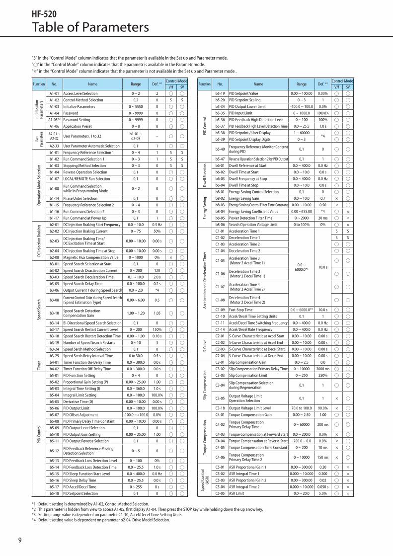
“S” in the “Control Mode” column indicates that the parameter is available in the Set up and Parameter mode.“ ” in the “Control Mode” column indicates that the parametr is available in the Parametr mode.“×” in the “Control Mode” column indicates that the parameter is not available in the Set up and Parameter mode .
*1 : Default setting is determined by A1-02, Control Method Selection.*2 : This parameter is hidden from view to access A1-05, first display A1-04. Then press the STOP key while holding down the up arrow key.*3 : Setting range value is dependent on parameter C1-10, Accel/Decel Time Setting Units.*4 : Default setting value is dependent on parameter o2-04, Drive Model Selection.

10
Table of Parameters
Function No. Name Range Def. *1Control Mode
V/f SV
Carr
ier F
requ
ency C6-01 Drive Duty Selection 0,1 0 S S
C6-02 Carrier Frequency Selection 1 ~ B,F 2 S S
C6-03 Carrier Frequency Upper Limit 1.0 ~ 15.0
*4C6-04 Carrier Frequency Lower Limit 1.0 ~ 15.0 ×
C6-05 Carrier Frequency Proportional Gain 00 ~ 99 ×
Freq
uenc
y Re
fere
nce
d1-01 Frequency Reference 1
0.00 ~400.00 0.00Hz
S S
d1-02 Frequency Reference 2 S S
d1-03 Frequency Reference 3 S S
d1-04 Frequency Reference 4 S S
d1-05 Frequency Reference 5
d1-06 Frequency Reference 6
d1-07 Frequency Reference 7
d1-08 Frequency Reference 8
d1-09 Frequency Reference 9
d1-10 Frequency Reference 10
d1-11 Frequency Reference 11
d1-12 Frequency Reference 12
d1-13 Frequency Reference 13
d1-14 Frequency Reference 14
d1-15 Frequency Reference 15
d1-16 Frequency Reference 16
d1-17 Jog Frequency Reference 0.00 ~ 400.00 5.00 Hz S S
Freq
.Li
mits
d2-01 Frequency Reference Upper Limit 0.0 ~ 110.0 100.0%
d2-02 Frequency Reference Lower Limit 0.0 ~ 110.0 0.0%
d2-03 Master Speed Reference Lower Limit 0.0 ~ 110.0 0.0%
Jum
p Fr
eque
ncy d3-01 Jump Frequency 1 0.0 ~ 400.0 0.0 Hz
d3-02 Jump Frequency 2 0.0 ~ 400.0 0.0 Hz
d3-03 Jump Frequency 3 0.0 ~ 400.0 0.0 Hz
d3-04 Jump Frequency Width 0.0 ~ 20.0 1.0 Hz
Freq
uenc
y Re
fere
nce
Hol
d
d4-01 Frequency Reference Hold Function Selection 0,1 0
d4-03 Frequency Reference Bias Step(Up/Down 2)
0.00 ~99.99 0.00Hz
d4-04 Frequency Reference Bias Accel/Decel (Up/Down 2) 0,1 0
d4-05 Frequency Reference Bias Operation Mode Selection (Up/Down 2) 0,1 0
d4-06 Frequency Reference Bias (Up/Down 2) -99.9 ~+100.0 0.0%
d4-07 Analog Frequency Reference Fluctuation Limit (Up/Down 2)
0.1 ~+100.0 1.0%
d4-08 Frequency Reference Bias Upper Limit(Up/Down 2) 0.0 ~ 100.0 100.0%
d4-09 Frequency Reference Bias Lower Limit (Up/Down 2)
-99.9 ~0.0 0.0%
d4-10 Up/Down Frequency Reference Limit Selection 0,1 0
Offs
et
Freq
. d7-01 Offset Frequency 1 -100.0 ~ +100.0 0.0%
d7-02 Offset Frequency 2 -100.0 ~ +100.0 0.0%
d7-03 Offset Frequency 3 -100.0 ~ +100.0 0.0%
V/f P
atte
rn C
hara
cter
istic
s
E1-01*2 Input Voltage Setting 155 ~ 255 *4 S S
E1-03 V/f Pattern Selection 0 ~ F F
E1-04 Maximum Output Frequency 40.0 ~ 400.0 60.0 Hz S S
E1-05*2 Maximum Output Voltage 0.0 ~ 255.0 200.0 V S S
E1-06 Base Frequency 0.0 ~ E1-04 60.0 Hz S S
E1-07 Middle Output Frequency 0.0 ~ E1-04 3.0 Hz
E1-08 Middle Output Frequency Voltage 0.0 ~ 255.0 *4
Function No. Name Range Def. *1Control Mode
V/f SV
V/f P
atte
rn
Char
acte
ristic
s E1-09 Minimum Output Frequency 0.0 ~ E1-04 1.5 Hz S S
E1-10 Minimum Output Frequency Voltage 0.0 ~ 255.0 *4
E1-11 Middle Output Frequency 2 0.0 ~ E1-04 0.0 Hz
E1-12*2 Middle Output Frequency Voltage 2 0.0 ~ 255.0 0.0 V
E1-13*2 Base Voltage 0.0 ~ 255.0 0.0 V S
Mot
or P
aram
eter
s
E2-01 Motor Rated Current Rated Current10 ~ 200%
*4
S S
E2-02 Motor Rated Slip 0.00 ~ 20.00
E2-03 Motor No-Load Current 0 ~ E2-01 below
E2-04 Number of Motor Poles 2 ~ 48 4pole
E2-05 Motor Line-to-Line Resistance 0.000 ~ 65.000*4
E2-06 Motor Leakage Inductance 0.0 ~ 40.0
E2-07 Motor Iron-Core Saturation Coefficient 1 0.00 ~ 0.50 0.50 ×
E2-08 Motor Iron-Core Saturation Coefficient 2 E2-07 ~ 0.75 0.75 ×
E2-09 Motor Mechanical Loss 0.0 ~ 10.0 0.0% ×
E2-10 Motor Iron Loss for Torque Compensation 0 ~ 65535
*4×
E2-11 Motor Rated Output 0.00 ~ 650.00 S S
E2-12 Motor Iron-Core Saturation Coefficient 3 1.30 ~ 5.00 1.30 ×
Mot
or 2
V/f
Cha
ract
erist
ics
E3-01 Motor 2 Control Method 0,2 0
E3-04 Motor 2 Max Output Frequency 40.0 ~ 400.0 60.0 Hz
E3-05*2 Motor 2 Max Voltage 0.0 ~ 255.0 200.0 V
E3-06 Motor 2 Base Frequency 0.0 ~ E3-04 60.0 Hz
E3-07 Motor 2 Mid Output Freq. 0.0 ~ E3-04 3.0 Hz
E3-08*3 Motor 2 Mid Output Freq. Voltage 0.0 ~ 255.0 13.6 V(26.6 V)
E3-09 Motor 2 Min. Output Freq. 0.0 ~ E3-04 1.5 Hz
E3-10*3 Motor 2 Min. Output Freq. Voltage 0.0 ~ 255.0 9.1 V(17.7V)
E3-11 Motor 2 Mid Output Frequency 2 0.0 ~ E3-04 0.0 Hz
E3-12*2 Motor 2 Mid Output Frequency Voltage 2 0.0 ~ 255.0 0.0 V
E3-13*2 Motor 2 Base Voltage 0.0 ~ 255.0 0.0 V S
Mot
or 2
Par
amet
ers
E4-01 Motor 2 Rated Current Rated Current10 ~ 200%
*4E4-02 Motor 2 Rated Slip 0.00 ~ 20.00
E4-03 Motor 2 Rated No- Load Current 0 ~ E4-01 below
E4-04 Motor 2 Motor Poles 2 ~ 48 4pole
E4-05 Motor 2 Line-to- Line Resistance 0.000 ~ 65.000*4
E4-06 Motor 2 Leakage Inductance 0.0 ~ 40.0
E4-07 Motor 2 Motor Iron-Core Saturation Coefficient 1 0.00 ~ 0.50 0.50 ×
E4-08 Motor 2 Motor Iron-Core Saturation Coefficient 2
Setting of E4-07 ~ 0.75 0.75 ×
E4-09 Motor 2 Mechanical Loss 0.0 ~ 10.0 0.0 ×
E4-10 Motor 2 Iron Loss 0 ~ 65535*4
×
E4-11 Motor 2 Rated Capacity 0.00 ~ 650.00 ×
E4-12 Motor 2 Iron-Core Saturation Coefficient 3 1.30 ~ 5.00 1.30 ×
E4-14 Motor 2 Slip Compensation Gain 0.0 ~ 2.5 0.0
E4-15 Torque Compensation Gain Motor 2 0.00 ~ 2.50 1.00
E5-39 Current Detection Delay Time -1000 to 1000 0µs
PG S
etup
Par
amet
ers
F1-02 Operation Selection at PG Open Circuit (PGo) 0 ~ 3 1 ×
F1-03 Operation Selection at Overspeed (oS) 0 ~ 3 1 ×
F1-04 Operation Selection at Deviation 0 ~ 3 3 ×
F1-08 Overspeed Detection Level 0 ~ 120 115% ×
F1-09 Overspeed Detection Delay Time 0.0 ~ 2.0 1.0 ×
*1 : Default setting is determined by A1-02, Control Method Selection.*2 : Values shown here are for 200 V class drives. Double the value when using a 400 V class drive.*3 : Values shown here are for 200 V class drives. ( ) the value when using a 400 V class drive.*4 : Default setting value is dependent on parameter o2-04, Drive Model Selection.

11
Function No. Name Range Def. *1Control Mode
V/f SV
PG S
etup
Pa
ram
eter
s F1-10 Excessive Speed Deviation Detection Level 0 ~ 50 10% ×
F1-11 Excessive Speed Deviation Detection Delay Time 0.0 ~ 10.0 0.5 s ×
F1-14 PG Open-Circuit Detection Time 0.0 ~ 10.0 2.0 s ×
Seria
l Com
mun
icat
ions
Opt
ion
Card
F6-01 Communications Error Operation Selection 0 ~ 3 1
F6-02 External Fault from Comm. Option Selection 0,1 0
F6-03 External Fault from Comm. Option Operation Selection 0 ~ 3 1
F6-04 Bus Error Detection Time 0.0 ~ 5.0 2.0 s
F6-07 NetRef/ComRef Function Selection 0,1 0
F6-08 Reset Communication Parameters 0,1 0
F6-10 CC-Link Node Address 0 ~ 64 0
F6-11 CC-Link Communications Speed 0 ~ 4 0
F6-14 BUS Error Auto Reset 0,1 0
F6-50 DeviceNet MAC Address 0 ~ 64 0
F6-51 Device Net Communications Speed 0 ~ 4 0
F6-52 DeviceNet PCA setting 0 ~ 255 21
F6-53 DeviceNet PPA setting 0 ~ 255 71
F6-54 54 DeviceNet Idle Mode Fault Detection 0,1 0
F6-55 DeviceNet Baud Rate Monitor 0 ~ 2(Read only) -
F6-56 DeviceNet Speed Scaling Factor -15 ~ 15 0
F6-57 DeviceNet Current Scaling Factor -15 ~ 15 0
F6-58 DeviceNet Torque Scaling Factor -15 ~ 15 0
F6-59 DeviceNet Power Scaling Factor -15 ~ 15 0
F6-60 DeviceNet Voltage Scaling Factor -15 ~ 15 0
F6-61 DeviceNet Time Scaling Factor -15 ~ 15 0
F6-62 DeviceNet Heartbeat Interval 0 ~ 10 0
F6-63 MAC ID Memory 0 ~ 63(Read only) -
Mul
ti-Fu
nctio
n Di
gita
l Inp
ut
H1-01 Multi-Function Digital Input Terminal S1 Function Selection
1 ~ 9F
40
H1-02 Multi-Function Digital Input Terminal S2 Function Selection 41
H1-03 Multi-Function Digital Input Terminal S3 Function Selection
0 ~ 9F
24
H1-04 Multi-Function Digital Input Terminal S4 Function Selection 14
H1-05 Multi-Function Digital Input Terminal S5 Function Selection 3(0)
H1-06 Multi-Function Digital Input Terminal S6 Function Selection 4(3)
H1-07 Multi-Function Digital Input Terminal S7 Function Selection 6(4)
Mul
ti-Fu
nctio
n Di
gita
l O
utpu
ts
H2-01 Terminal MA, MB and MC Function Selection (relay)
0 ~ 192
E
H2-02 Terminal P1 Function Selection (open- collector) 0
H2-03 Terminal P2 Function Selection (open- collector) 2
H2-06 Watt Hour Output Unit Selection 0 ~ 4 0
Anal
og In
puts
H3-01 Terminal A1 Signal Level Selection 0,1 0
H3-02 Terminal A1 Function Selection 0 ~ 41 0
H3-03 Terminal A1 Gain Setting -999.9 ~999.9 100.0%
H3-04 Terminal A1 Bias Setting -999.9 ~999.9 0.0%
H3-09 Terminal A2 Signal Level Selection 0 ~ 3 2
H3-10 Terminal A2 Function Selection 0 ~ 41 0
H3-11 Terminal A2 Gain Setting -999.9 ~ 999.9 100.0%
H3-12 Terminal A2 Bias Setting -999.9 ~ 999.9 0.0%
H3-13 Analog Input Filter Time Constant 0.00 ~ 2.00 0.03 s
H3-14 Analog Input Terminal Enable Selection 1,2,7 7
Function No. Name Range Def. *1Control Mode
V/f SV
Anal
og
Inpu
ts H3-16 Terminal A1 Offset -500 ~ 500 0
H3-17 Terminal A2 Offset -500 ~ 500 0
Mul
ti-Fu
nctio
n An
alog
Out
puts H4-01 Multi-Function Analog Output Terminal AM 000 ~ 999 102
H4-02 Multi-Function Analog Output Terminal AM Gain -999.9 ~999.9 100.0% S S
H4-03 Multi-Function Analog Output Terminal AM Bias -999.9 ~999.9 0.0%
MEM
OBU
S/M
odbu
s Com
mun
icat
ions
H5-01 Drive Node Address 0 ~ FFH 1F
H5-02 Communication Speed Selection 0 ~ 8 3
H5-03 Communication Parity Selection 0 ~ 2 0
H5-04 Stopping Method After Communication Error 0 ~ 3 3
H5-05 Communication Fault Detection Selection 0,1 1
H5-06 Drive Transmit Wait Time 5 ~ 65 5 ms
H5-07 RTS Control Selection 0,1 1
H5-09 CE Detection Time 0.0 ~ 10.0 2.0 s
H5-10 Unit Selection for MEMOBUS/Modbus Register 0025H 0,1 0
H5-11 Communications ENTER Function Selection 0,1 1
H5-12 Run Command Method Selection 0,1 0
Pulse
Tra
in In
put/
Out
put
H6-01 Pulse Train Input Terminal RP Function Selection 0 ~ 3 0
H6-02 Pulse Train Input Scaling 100 ~ 32000 1440 Hz
H6-03 Pulse Train Input Gain 0.0 ~ 1000.0 100.0%
H6-04 Pulse Train Input Bias -100.0 ~+100.0 0.0%
H6-05 Pulse Train Input Filter Time 0.00 ~ 2.00 0.10 s
H6-06 Pulse Train Monitor Terminal MP Selection
000,031,101,102,105,116,501,502 102
H6-07 Pulse Train Monitor Scaling 0 ~ 32000 1440 Hz
H6-08 Pulse Train Min. Frequency 0.1 ~ 1000.0 0.5 Hz
Mom
enta
ry P
ower
Los
s
L1-01 Motor Overload Protection Selection 0 ~ 2,6 1 S S
L1-02 Motor Overload Protection Time 0.1 ~ 5.0 1.0 min
L1-03 Motor Overheat Alarm Operation Selection (PTC input) 0 ~ 3 3
L1-04 Motor Overheat Fault Operation Selection (PTC input) 0 ~ 2 1
L1-05 Motor Temperature Input Filter Time (PTC input) 0.00 ~ 10.00 0.20 s
L1-08 Electrothermal Level Setting 1 . A10~150% *4
L1-09 Electrothermal Level Setting 2
L1-13 Continuous Electrothermal Operation Selection 0,1 1
L1-22*2 Leakage Current Filter Time Constant 1 0.0 ~ 60.0 20.0S
L1-23*2 Leakage Current Filter Time Constant 2 0.0 ~ 60.0 1.0S
Stal
l Pre
vent
ion
Func
tion
L2-01 Momentary Power Loss Operation Selection 0 ~ 2 0
L2-02 Momentary Power Loss Ride-Thru Time 0.0 ~ 25.5
*4
L2-03 Momentary Power Loss Minimum Baseblock Time 0.1 ~ 5.0
L2-04 Momentary Power Loss Voltage Recovery Ramp Time 0.0 ~ 5.0
L2-05*3 Undervoltage Detection Level (Uv) 150 ~ 210
L2-06 KEB Deceleration Time 0.0 ~ 200.0 0.0s
L2-07 KEB Acceleration Time 0.0 ~ 25.5 0.0s
L2-08 KEB Start Output Frequency Reduction 0 ~ 300 100%
L2-11*3 Desired DC Bus Voltage during KEB 150 ~ 400 E1-01×1.22(V)
Stal
l Pre
vent
ion
Func
tion
L3-01 Stall Prevention Selection during Acceleration 0 ~ 2 1
L3-02 Stall Prevention Level during Acceleration 0 ~ 150 *4
L3-03 Stall Prevention Limit during Acceleration 0 ~ 100 50%
L3-04 Stall Prevention Selection during Deceleration 0 ~ 4,7 0 S S
L3-05 Stall Prevention Selection during Run 0 ~ 2 1 ×
L3-06 Stall Prevention Level during Run 30 ~ 150 *4 ×
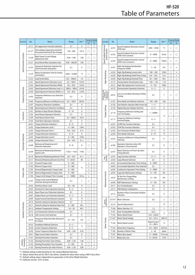
*1 : Default setting is determined by A1-02, Control Method Selection.*2 : Parameter can be changed and displayed at parameter C6-02=B.*3 : Values shown here are for 200 V class drives. Double the value when using a 400 V class drive.*4 : Default setting value is dependent on parameter o2-04, Drive Model Selection.
Table of Parameters
12
Function No. Name Range Def. *1Control Mode
V/f SV
Stal
l Pre
vent
ion
Func
tion
L3-11 Ov Suppression Function Selection 0,1 0
L3-17*3 Overvoltage Suppression and Stall Prevention Desired DC Bus Voltage 150 ~ 400 375 V
L3-20 Main Power Circuit Voltage Adjustment Gain 0.00 ~ 5.00 1.00
L3-21 Accel/Decel Rate Calculation Gain 0.00 ~ 200.00 1.00
L3-23 Automatic Reduction Selection for Stall Prevention during Run 0,1 0
L3-24 Motor Acceleration Time for Inertia Calculations 0.001 ~10.000 *3
L3-25 Load Inertia Ratio 0.0 ~ 1000.0 1.0
Freq
uenc
y De
tect
ion
L4-01 Speed Agreement Detection Level 0.0 ~ 400.0 0.0 Hz
L4-02 Speed Agreement Detection Width 0.0 ~ 20.0 2.0 Hz
L4-03 Speed Agreement Detection Level (+/-) -400.0 ~ 400.0 0.0 Hz
L4-04 Speed Agreement Detection Width (+/-) 0.0 ~ 20.0 2.0 Hz
L4-05 Frequency Reference Loss Detection Selection 0,1 0
L4-06 Frequency Reference at Reference Loss 0.0 ~ 100.0 80.0%
L4-07 Frequency Detection Conditions 0,1 0
L4-08 Speed Agreement Detection Conditions 0,1 0
Faul
t Res
et
L5-01 Number of Auto Restart Attempts 0 ~ 10 0
L5-02 Auto Restart Operation Selection 0,1 0
L5-04 Fault Reset Interval Time 0.5 ~ 600.0 10.0 s
L5-05 Fault Reset Operation Selection 0,1 0
Ove
rtor
que
Dete
ctio
n
L6-01 Torque Detection Selection 1 0 ~ 8 0
L6-02 Torque Detection Level 1 0 ~ 300 150%
L6-03 Torque Detection Time 1 0.0 ~ 10.0 0.1s
L6-04 Torque Detection Selection 2 0 ~ 8 0
L6-05 Torque Detection Level 2 0 ~ 300 150%
L6-06 Torque Detection Time 2 0.0 ~ 10.0 0.1 s
L6-08 Mechanical Weakening (oL5) Detection Operation 0 ~ 8 0
L6-09 Mechanical Weakening Detection Speed Level -110.0 ~ 110.0 110%
L6-10 Mechanical Weakening Detection Time 0.0 ~ 10.0 0.1 s
L6-11 Mechanical Weakening Detection Start Time 0 ~ 65535 0h
Torq
ue L
imit
L7-01 Forward Torque Limit 0 ~ 300
*3
×
L7-02 Reverse Torque Limit 0 ~ 300 ×
L7-03 Forward Regenerative Torque Limit 0 ~ 300 ×
L7-04 Reverse Regenerative Torque Limit 0 ~ 300 ×
L7-06 Torque Limit Integral Time Constant 5 ~ 10000 50 ms ×
L7-07 Torque Limit Control Method Selection during Accel/Decel 0,1 1 ×
Har
dwar
e Pr
otec
tion
L8-02 Overheat Alarm Level 50 ~ 130 *3
L8-03 Overheat Pre-Alarm Operation Selection 0 ~ 4 3
L8-05 Input Phase Loss Protection Selection 0,1 0
L8-07 Output Phase Loss Protection Selection 0 ~ 2 0
L8-09 Output Ground Fault Detection Selection 0,1 *3
L8-10 Heatsink Cooling Fan Operation Selection 0,1 0
L8-11 Heatsink Cooling Fan Operation Delay Time 0 ~ 300 60 s
L8-12 Ambient Temperature Setting -10 ~ 50 40°C
L8-15 oL2 Characteristics Selection at Low Speeds 0,1 1
L8-18 Soft Current Limit Selection 0,1 0
L8-19 Frequency Reduction Rate during oH Pre-Alarm 0.1 ~ 0.9 0.8
L8-35 Installation Method Selection 0 ~ 2*3
L8-38 Carrier Frequency Reduction 0 ~ 2
L8-40 Carrier Frequency Reduction Time 0.00 ~ 2.00 0.50
L8-41 High Current Alarm Selection 0,1 0
Hun
ting
Prev
entio
n n1-01 Hunting Prevention Selection 0,1 1 ×
n1-02 Hunting Prevention Gain Setting 0.00 ~ 2.50 1.00 ×
n1-03 Hunting Prevention Time Constant 0 ~ 500 10 ×
n1-05 Hunting Prevention Gain while in Reverse 0.00 ~ 2.50 0.00 ×
Function No. Name Range Def. *1Control Mode
V/f SV
Spee
d Fe
edba
ck D
etec
tion
Cont
rol F
unct
ion n2-01 Speed Feedback Detection Control
(AFR) Gain 0.00 ~ 10.00 *3 ×
n2-02 Speed Feedback Detection Control (AFR) Time Constant 0 ~ 2000 50 ms ×
n2-03 Speed Feedback Detection Control (AFR) Time Constant 2 0 ~ 2000 750ms ×
Hig
h-Sl
ip B
raki
ng
n3-01 High-Slip Braking Deceleration Frequency Width 1 ~ 20 5% ×
n3-02 High-Slip Braking Current Limit 100 ~ 200 150% ×
n3-03 High-Slip Braking Dwell Time at Stop 0.0 ~ 10.0 1.0 s ×
n3-04 High-Slip Braking Overload Time 30 ~ 1200 40 s ×
n3-13 Overexcitation Deceleration Gain 1.00 ~ 1.40 1.10
n3-21 High-Slip Suppression Current Level 0 ~ 150 100%
n3-23 Overexcitation Operation Selection 0 ~ 2 0
Onl
ine
Tuni
ng
of M
otor
Li
ne-t
o-Li
ne
Resis
tanc
e
n6-01 Line-to-Line Motor Resistance Online Tuning 0,1 1 ×
Disp
lay
Sett
ings
o1-01 Drive Mode Unit Monitor Selection 104 ~ 699 106
o1-02 User Monitor Selection After Power Up 1 ~ 5 1
o1-03 Digital Operator Display Selection 0 ~ 3 0
o1-10 Frequency Reference Setting and User-Set Display 1 ~ 60000
*3
o1-11 Frequency Reference Setting / Decimal Display 0 ~ 3
Ope
rato
r Key
pad
Func
tions
o2-01 LO/RE Key Function Selection 0,1 1
o2-02 STOP Key Function Selection 0,1 1
o2-03 User Parameter Default Value 0 ~ 2 0
o2-04 Drive Model Selection 0 ~ FF *3
o2-05 Frequency Reference Setting Method Selection 0,1 0
o2-06 Operation Selection when LED Operator is Disconnected 0,1 0
o2-07 Motor Direction at Power Up when Using Operator 0,1 0
Copy
Fu
nctio
n o3-01 Copy Function Selection 0 ~ 3 0
o3-02 Copy Allowed Selection 0,1 0
Mai
nten
ance
Per
iod
o4-01 Accumulated Operation Time Setting 0 ~ 9999 0
o4-02 Accumulated Operation Time Selection 0,1 1
o4-03 Cooling Fan Operation Time Setting 0 ~ 9999 0
o4-05 Capacitor Maintenance Setting 0 ~ 150 0%
o4-07 DC Bus Pre-Charge Relay Maintenance Setting 0 ~ 150 0%
o4-09 IGBT Maintenance Setting 0 ~ 150 0%
o4-11 U2, U3 Initialization 0,1 0
o4-12 kWh Monitor Initialization 0,1 0
o4-13 Number of Run Commands Initialize Selection 0,1 0
Spec
ial
Adju
stm
ents
S1-01*4 Motor Selection 0,2 2
S2, S3 Special Adjustments - *3 ×
Mot
or T
unin
g
T1-00 Motor Selection 1/2 1,2 1
T1-01 Auto-Tuning Mode Selection 0,2,3*3
T1-02 Motor Rated Power 0.03 ~ 650.00
T1-03*2 Motor Rated Voltage 0.0 ~ 255.5 200.0 V
T1-04 Motor Rated Current Rated Current10 ~ 200% *3
T1-05 Motor Base Frequency 0.0 ~ 400.0 60.0 Hz
T1-06 Number of Motor Poles 2 ~ 48 4pole
T1-07 Motor Base Speed 0 ~ 24000 1750 r/min
T1-11 Motor Iron Loss 0 ~ 65535 14 W ×
*1 : Default setting is determined by A1-02, Control Method Selection.*2 : Values shown here are for 200 V class drives. Double the value when using a 400 V class drive.*3 : Default setting value is dependent on parameter o2-04, Drive Model Selection.*4 : Software version : 5551 or later.
Table of Parameters

13
Outline Drawing
Input voltage Inverter modelDimensions (mm)
DrawingW H D W1 H1 H2 D1 t1 Approx.weight (kg)
1-phase
200V class
HF520S-A20 68 128 76 56 118 5 6.5 3 0.6
A
HF520S-A40 68 128 118 56 118 5 38.5 5 1.0
3-phase
200V class
HF5202-A20 68 128 76 56 118 5 6.5 3 0.6
HF5202-A40 68 128 108 56 118 5 38.5 5 0.9
HF5202-A75 68 128 128 56 118 5 58.5 5 1.1
Input voltage Inverter modelDimensions (mm)
DrawingW H D W1 H1 H2 D1 t1 Approx.weight (kg)
1-phase
200V class
HF520S-A75 108 128 137.5 96 118 5 58 5 1.7
B
HF520S-1A5 108 128 154 96 118 5 58 5 1.8
HF520S-2A2 140 128 163 128 118 5 65 5 2.4
3-phase
200V class
HF5202-1A5 108 128 129 96 118 5 58 5 1.7
HF5202-2A2 108 128 137.5 96 118 5 58 5 1.7
HF5202-3A7 140 128 143 128 118 5 65 5 2.4
3-phase
400V class
HF5204-A20 108 128 81 96 118 5 10 5 1.0
HF5204-A40 108 128 99 96 118 5 28 5 1.2
HF5204-A75 108 128 137.5 96 118 5 58 5 1.7
HF5204-1A5 108 128 154 96 118 5 58 5 1.7
HF5204-2A2 108 128 154 96 118 5 58 5 1.7
HF5204-3A7 140 128 143 128 118 5 65 5 2.4
Input voltage Inverter modelDimensions (mm)
W H D W1 H1 H2 H3 H4 H5 H6 D1 t1 d Approx.weight (kg)
3-phase
200V class
HF5202-5A5 140 254 140 122 234 248 6 13 13 1.5 55 5 M5 3.8
HF5202-7A5 140 254 140 122 234 248 6 13 13 1.5 55 5 M5 3.8
3-phase
400V class
HF5204-5A5 140 254 140 122 234 248 6 13 13 1.5 55 5 M5 3.8
HF5204-7A5 140 254 140 122 234 248 6 13 13 1.5 55 5 M5 3.8
D1
t1
D
2-M4W1
H1
H2W
H
t1
DD1
4-M4
H
W1
W H2
H1
W1
W H5
H2
H4
HH
3 D1t1
D
H1
4-d
H6
Fig.A Fig.B
14
Applicable Wiring for Accessories and Options
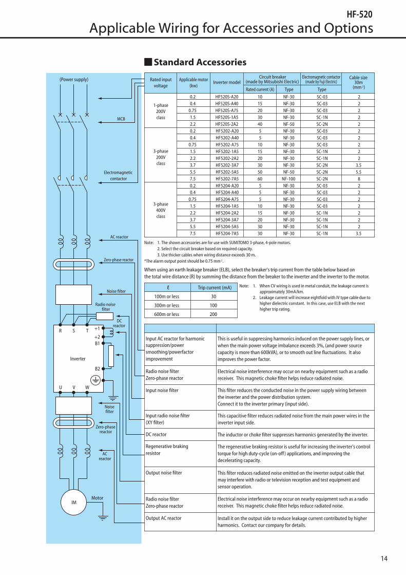
Standard Accessories

15
Peripheral Equipment
Caution in Selecting Peripheral Equipment
Wiring and connection1. Be sure to connect the power supply to RST (input terminals) and the motor to U, V, W (output terminals).
2. Be sure to connect the grounding terminal. ( mark)Inverters generate high frequency, increasing leakage current. Be sure to ground the inverter and motor.
Wiringbetweeninverter andmotor
Electromagnetic contactor
When using an electromagnetic contactor between the inverter and motor, do not turn the contactor ON or OFF during inverter operation.
Thermal relay
Install a thermal relay that matches the motor in the following cases:*Install a thermal relay for each motor when operating more than one motor with one inverter.*Set the current of the thermal relay at the rated motor current x 1.1. When the wiring length is long (more than 10 m), the
thermal relay may be activated too quickly. Install an AC reactor or current sensor on the output side.*When motors are to be operated with the rated current exceeding the adjustable level of the built-in electronic thermal relay.
Earth leakage breakerInstall an earth leakage breaker on the input side for protection of the inverter wiring and operators.Conventional earth leakage breakers may malfunction because of high harmonics from the inverter; therefore use an earth leakage breaker that is applicable to the inverter. The leakage current differs according to the cable length. Refer to p.14.
Wiring distance
The wiring distance between the inverter and operation panel should be less than 30m. If it exceeds 30m, use a current/voltage converter, etc. Use shielded cable for wiring.When the wiring distance between the motor and inverter is long, the leakage current from high harmonics may cause the protective function of the inverter and peripheral equipment to be activated.The situation will be improved by an AC reactor installed on the output side of the inverter.Select appropriate cable to prevent voltage drop. (Large voltage drop lowers the torque.)
Phase-advanced capacitorDo not use a phase-advanced capacitor.When a power factor improving capacitor is connected between the inverter and motor, the capacitor may be heated or broken by the higher harmonics in the inverter output.

16
External Options
Frequency Reference Setting Unit
No. VR07
Cable for Engineering Tool (Model No. WV103)
Connection Method
Communication Unit
50
50
ø9.5
ø3
ø25
ø30 12
Panel
Bakelite plate
2415
(0.8t)
Panel cut
Potentiometer 1kΩ,2W
0
10
20
30
4050
60
70
80
90
100
Outline Drawing (mm)When installing the communication unit in the HF-520, the
27mm depth becomes long.
Note) 1. Engineering Tool for drive setup and parameter management The installation files can be obtained at no Charge from : http://www.shi.co.jp/ptc/
Item SpecificationConnector DSUB 9P
Cable Length 3 m
Name No.CC-Link Unit SI-C3/V-HDeviceNet Unit SI-N3/V-H
WV103(3 m)
• Engineering Tool for PC (SDWP001)
27
22 13
Unit : mm
RJ45 Connector

17
LED Operator
3
1
ICS-3
ICS-1
Cable length L(m)Model
JVOP-182-H Dimensions for the panel cutICS-1 , 3
L
90 78
607.9
Unit : mm
12.2 1.6 M3 × 2 depth5
44
15
22
22
14
2622
78
2
Unit : mm
External Options
Regenerative Braking Resistor
100% braking torque: 10 sec 10% ED
Type of thermal relay: TR-ONH
Rated power
(W)
Dimensions (mm) Weight(g)
F G H J K L M N
200 28 26 22 6 53 287 306 4 340
300 44 40 40 10 78 309 335 5 840
400 44 40 40 10 78 385 411 5 1000
750 57 40 40 10 84 355 381 5 1360
Voltage(V)
Capacity(kW)
Braking resistorThermal relay set value (A)Part No. Rated
power Resistance Qty
200V
0.2 Y135AA201 200W 400Ω 1 0.830.4 Y135AA200 200W 200Ω 1 0.83
0.75 Y135AA205 300W 200Ω 1 1.251.5 Y135AA204 300W 80Ω 1 1.252.2 Y135AA208 400W 70Ω 1 1.73.7 Y135AA203 300W 20Ω 2-pc. series 2.15.5 X435AC069 750W 10Ω 2-pc. series 5.37.5 X435AC069 750W 10Ω 2-pc. series 5.3
400V
0.2, 0.4 Y135AA202 200W 750Ω 1 0.420.75 Y135AA207 300W 750Ω 1 0.631.5 Y135AA206 300W 400Ω 1 0.632.2 Y135AA209 400W 250Ω 1 0.833.7 Y135AA204 300W 80Ω 2-pc. series 1.15.5 Y135AA209 400W 250Ω 3-pc. series 2.07.5 Y135AA209 400W 250Ω 3-pc. series 2.0
18
External Options
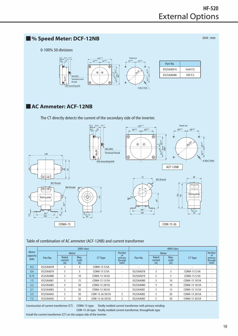
% Speed Meter: DCF-12NB
0-100% 50 divisions
AC Ammeter: ACF-12NB
The CT directly detects the current of the secondary side of the inverter.
ACF-12NB
COMA-15 COM-15-26
Table of combination of AC ammeter (ACF-12NB) and current transformer
Construction of current transformer (CT) COMA-15 type: Totally molded current transformer with primary winding COM-15-26 type: Totally molded current transformer, throughhole typeInstall the current transformer (CT) on the output side of the inverter.
Motorcapacity
(kW)
200V class 400V class
Part No.
Meter
CT Type
Numberof
primarythrough
holes
Part No.
Meter
CT Type
Numberof
primarythrough
holes
Ratedcurrent
[A]
Max.scale[A]
Ratedcurrent
[A]
Max.scale[A]
0.2 X525AA078 3 3 COMA-15 5/5A - - - - - -
0.4 X525AA079 5 5 COMA-15 5/5A - X525AA078 3 3 COMA-15 5/5A -
0.75 X525AA080 5 10 COMA-15 10/5A - X525AA079 5 5 COMA-15 5/5A -
1.5 X525AA081 5 15 COMA-15 15/5A - X525AA080 5 10 COMA-15 10/5A -
2.2 X525AA082 5 20 COMA-15 20/5A - X525AA080 5 10 COMA-15 10/5A -
3.7 X525AA083 5 30 COMA-15 30/5A - X525AA081 5 15 COMA-15 15/5A -
5.5 X525AA042 5 50 COM-15-26 50/5A 3 X525AA082 5 20 COMA-15 20/5A -
7.5 X525AA042 5 50 COM-15-26 50/5A 3 X525AA083 5 30 COMA-15 30/5A -
Part No.
X525AA014 1mA F.S.
X525AA048 10V F.S.
Unit : mm

19
External Options
DC Reactor for Power Factor Improvement and Harmonics Suppression
The DC reactor is available for improvement
of the power factor of the inverter, ensuring
power line impedance, and control of
higher harmonics.
AC Reactor for Power Factor Improvement and Harmonics Suppression
The AC reactor is available for improvement
of the power factor of the inverter, ensuring
proper power line impedance, and control of
higher harmonics.
* The AC reactor is for 3-phase input.
Applicable capacity
(kW)
SpecificationPart No.
Y220DAW W1 D D1 D2 D3 H H1 H2 G
Connection Terminal
Weight(kg)
InsulationCurrent(A)
L(mH)
200V
Series
0.2 1.0 29.7 032 52 35 40 32 20 22 65 - 300 dia.4 M4 0.3 B0.4 2.0 14.8 033 52 35 40 32 20 22 75 - 300 dia.4 M4 0.4 B
0.75 3.75 9.72 034 52 35 50 42 25 27 85 - 300 dia.4 M4 0.6 B1.5 7.5 4.83 035 74 50 45 37 - - 120 145 - dia.5 M5 1.0 B2.2 11.0 3.41 036 74 50 45 37 - - 120 145 - dia.5 M5 1.1 B3.7 18.5 2.13 037 90 60 62 52 - - 140 170 - dia.5 M5 2.0 B5.5 28.0 1.47 038 90 60 62 52 - - 140 170 - dia.5 M5 2.4 B7.5 38.0 1.11 039 100 80 95 80 - - 140 170 - 5.5×7 M5 3.5 B
400V
Series
0.2 0.5 116 002 52 35 40 32 20 22 65 - 300 dia.4 M4 0.3 B0.4 1.0 59.3 003 52 35 40 32 20 22 75 - 300 dia.4 M4 0.4 B
0.75 1.88 38.9 004 52 35 50 42 25 27 85 - 300 dia.4 M4 0.6 B1.5 3.75 19.3 005 59 40 60 47 30 35 100 - 300 dia.4 M4 0.9 B2.2 5.5 13.7 006 74 50 45 37 - - 120 140 - dia.5 M5 1.1 B3.7 9.25 8.52 007 74 50 70 62 - - 120 145 - dia.5 M5 1.8 B5.5 14.0 5.87 008 90 60 62 52 - - 140 165 - dia.5 M5 1.5 B7.5 19.0 4.46 009 100 80 95 80 - - 140 165 - 5.5×7 M5 3.5 B
Applicable capacity (kW) SpecificationPart No.Y220DA
W DI D2 H1 H2 A B G L TWeight
(kg)Insulation
3-Phase 1-PhaseCurrent
(A)L
(mH)
200V
Series
0.2, 0.4 0.2 2.1 5.8 053 87 26 23 95 - 50 38 4 310 M4 1.0 B0.75 0.4 4.0 3.1 054 87 26 23 95 - 50 38 4 310 M4 1.1 B1.5 0.75 8.0 1.6 055 90 33 30 100 120 55 48 4 - M4 1.6 B2.2 - 11 1.2 056 113 35 30 116 140 55 43 4 - M4 2.1 B3.7 1.5/2.2 17 0.7 057 113 35 30 116 140 55 43 4 - M5 2.4 B5.5 - 24 0.5 058 146 35 35 147 180 80 50 5 - M5 3.9 F7.5 - 33 0.4 059 150 35 35 150 185 80 50 5 - M6 4.4 F
400V
Series
0.2, 0.4
-
1.2 22 080 87 26 23 95 - 50 38 4 310 M4 1.0 B0.75 2.1 12 081 90 26 23 96 - 50 38 4 310 M4 1.1 B1.5 4.0 6.5 082 90 33 30 100 - 55 48 4 310 M4 1.7 B2.2 5.5 4.6 083 113 33 30 115 - 55 43 4 310 M4 2.5 B3.7 9.0 2.9 084 113 35 30 115 140 55 43 4 - M4 2.8 B5.5 13 2.0 085 153 35 35 145 175 80 50 5 - M4 4.2 B7.5 17 1.5 086 162 37 35 145 175 80 50 5 - M5 4.4 B
Unit : mm
Unit : mm

20
External Options
Noise Filter3-phase 200V class
1-phase 200V class
3-phase 400V class
Input-side Noise Filter Output-side Noise Filter
1030
0mm
4.547
.031
.05.
511
.0±
1.0
55.0
Soldering
Black and yellow/greenUL-1015AWG18
22dia.4.312
±1.
0
±1.0
±2
Capacitive filter (XY filter) Type: X480AC185
1. Connect the input-side filter between the power supply and inverter input terminal, and the output-side filter between the inverter output terminal and motor. Make the connection cable as short as possible.
2. Use grounding cable as thick as possible. Correctly ground the equipment.3. The input and output cables of the filter should be sufficiently separated.4. Do not connect the input-side filter to the inverter output (motor) side.
Applicable motor(kW)
Input side Output side
Type Part No. Type Part No.
0.2, 0.4NF3010A-VZ X480AC289
CC3005C-P X480AC1630.75, 1.5 CC3010C-P X480AC164
2.2NF3020A-VZ X480AC290
CC3015C-P X480AC1653.7 CC3020C-P X480AC1665.5 NF3030A-VZ X480AC291 CC3030C-P X480AC1677.5 NF3040A-VZ X480AC292 CC3045C-P X480AC168
Applicable motor(kW)
Input side Output side
Type Part No. Type Part No.
0.2, 0.4NF3010A-VZ X480AC289
CC3005C-P X480AC1630.75 CC3010C-P X480AC1641.5 NF3020A-VZ X480AC290 CC3015C-P X480AC1652.2 NF3030A-VZ X480AC291 CC3020C-P X480AC166
Applicable motor(kW)
Input side Output side
Type Part No. Type Part No.
0.2 to 1.5NF3010C-VZ X480AC296
CC3005C-P X480AC1632.2, 3.7 CC3010C-P X480AC164
5.5NF3020C-VZ X480AC297
CC3015C-P X480AC1657.5 CC3020C-P X480AC166
21
External Options
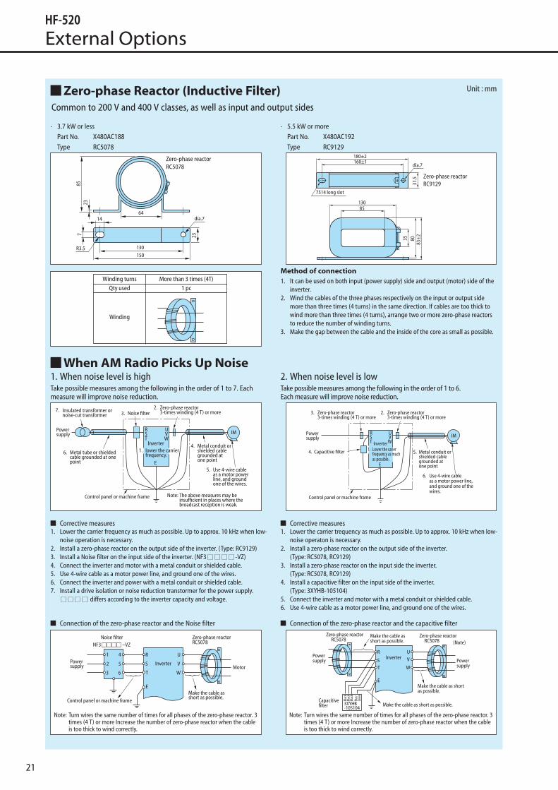
· 3.7 kW or less Part No. X480AC188 Type RC5078
· 5.5 kW or more Part No. X480AC192 Type RC9129
Method of connection1. It can be used on both input (power supply) side and output (motor) side of the
inverter.2. Wind the cables of the three phases respectively on the input or output side
more than three times (4 turns) in the same direction. If cables are too thick to wind more than three times (4 turns), arrange two or more zero-phase reactors to reduce the number of winding turns.
3. Make the gap between the cable and the inside of the core as small as possible.
1. When noise level is highTake possible measures among the following in the order of 1 to 7. Each measure will improve noise reduction.
Corrective measures1. Lower the carrier frequency as much as possible. Up to approx. 10 kHz when low-
noise operation is necessary.2. Install a zero-phase reactor on the output side of the inverter. (Type: RC9129)3. Install a Noise filter on the input side of the inverter. (NF3 -VZ)4. Connect the inverter and motor with a metal conduit or shielded cable.5. Use 4-wire cable as a motor power line, and ground one of the wires.6. Connect the inverter and power with a metal conduit or shielded cable.7. Install a drive isolation or noise reduction transtormer for the power supply.
differs according to the inverter capacity and voltage.
Connection of the zero-phase reactor and the Noise filter
2. When noise level is lowTake possible measures among the following in the order of 1 to 6.Each measure will improve noise reduction.
Corrective measures1. Lower the carrier trequency as much as possible. Up to approx. 10 kHz when low-
noise operaton is necessary.2. Install a zero-phase reactor on the output side of the inverter.
(Type: RC5078, RC9129)3. Install a zero-phase reactor on the input side the inverter.
(Type: RC5078, RC9129)4. Install a capacitive filter on the input side of the inverter.
(Type: 3XYHB-105104)5. Connect the inverter and motor with a metal conduit or shielded cable.6. Use 4-wire cable as a motor power line, and ground one of the wires.
Connection of the zero-phase reactor and the capacitive filter
Common to 200 V and 400 V classes, as well as input and output sides
Note: Turn wires the same number of times for all phases of the zero-phase reactor. 3 times (4 T) or more Increase the number of zero-phase reactor when the cable is too thick to wind correctly.
Note: Turn wires the same number of times for all phases of the zero-phase reactor. 3 times (4 T) or more Increase the number of zero-phase reactor when the cable is too thick to wind correctly.
Zero-phase Reactor (Inductive Filter)
When AM Radio Picks Up Noise
Unit : mm

22
Notes to Inverter Users
Measures to Take When Proximity Switch/photoelectric Switch, etc. MalfunctionTake possible measures among the following in the order of 1 to 12. Each measure will improve noise reduction.
Corrective measures 1. Use twisted pair/shielded wire as a sensor signal line, and connect the shielded
wire to common.2. Separate the inverter and power line from the sensor circuit as much as possible.
(More than 10 cm desirable)3. Remove the grounding wire when the power supply for the sensor is grounded.4. Lower the carrier frequency as much as possible. Up to approx. 10 kHz when low-
noise operation is necessary.
5. Install a zero-phase reactor on the output side of the inverter. (Type: RC5078, RC9129)
6. Install an LC filter on the input side of the inverter. (Type: FS)7. Install a capacitive filter on the input side of the inverter.
(Type: 3XYHB-105104)8. Use a metal conduit or shielded cable for power supply wiring.9. Use 4-wire cable as a motor power line, and ground one of the wires.10. Install a drive isolation or noise reduction transformer for the inverter power
supply.11. Ground the power supply for the sensor via a 0.01-0.1 →(630V 0.1µF)12. Separate the inverter power supply from the sensor power supply system.
Connection of the reactors and the capacitive filter
Continuous Operation Torque Characteristics
Motor Temperature RiseWhen a general-purpose motor is used in variable-speed operation with an inverter, the temperature rise of the motor will be slightly greater than in cases where commercial power is used. The causes are shown below:Influence of output waveform Unlike commercial power, the output waveform of an inverter is not a perfect sine wave, and contains higher harmonics. Therefore, the motor
loss increases and the temperature is slightly higher.Reduction in the motor cooling effect Motors are cooled by the fan on the motor itself. When the motor speed is reduced by an inverter, the cooling effect will decrease.
Therefore, lower the load torque or use an inverter motor to control temperature rise when the frequency is below the frequency of commercial power.
Note: Turn wires the same number of times for all phases of the zero-phase reactior. 3 times (4 T) or more. Increase the number of zero-phase reactors when the cable is too thick to wind correctly.
during slow-speed operation
Life of Major PartsThe electrolytic capacitor, cooling fan, and other parts used for inverters are consumables. Their life substantially depends on the operating condition of inverters. When replacement of the cooling fan is necessary, contact our dealer or service center.

23
Notes to Inverter Users
Precautions for Application of Inverter
Power supply1. When the inverter is connected directly to a large-capacity power supply (especially in a 400 V line), excessively large peak will flow in, breaking the
inverter unit. In such a case, install an AC reactor (option) on the input side of the inverter unit.
2. Install an AC reactor in the following cases as well.
1) There is a possibility of surge voltage generated in the power supply system: When surge energy flows into the inverter, OV tripping may result.2) When a large-capacity thyristor Leonard or other phase control units are installed
3. When the inverter is operated by a private power generator, secure a sufficiently large generation capacity for the inverter kVA in consideration of the influence of higher harmonic current on the generator.
Installation1. Do not install the inverter in places with poor environmental conditions subjected to dust, oil mist, corrosive gas, or inflammable gas.
2. In places where there is suspended matter in the air, install the inverter inside a “closed-type” panel to prevent entry of suspended matter. Determine the cooling method and dimensions of the panel so that the ambient temperature around the inverter will be lower than the allowable temperature.
3. Vertically install the inverter on a wall. Do not install it on wood or other inflammable products.
Handling1. Do not connect the output terminal UVW of the inverter to the power supply; otherwise the inverter will be broken. Carefully check the wiring for
correct arrangement before turning on the power.
2. It takes some time for the internal capacitors to discharge completely after the power is turned off. Check that the charge lamp on the printed circuit board is OFF before inspection.
Operation1. Do not start and stop the inverter frequently by means of an electromagnetic contactor (MC) installed on the input side of the inverter; otherwise
failure of the inverter will result.
2. When more than one motor is operated by one inverter, select the inverter capacity so that 1.1 times the total rated current of the motors will not exceed the rated output current of the inverter.
3. When an error occurs, the protective function is activated and the inverter trips and stops operation. In that case, motors will not stop immediately. When emergency stop is desired, use mechanical brakes as well.
4. The acceleration time of the motor is subject to the inertial moment of the motor and load, motor torque, and load torque.
1) When the acceleration time setting is too short, the stall prevention function is activated, and the setting time is elongated automatically. For stable acceleration and deceleration, set longer time so that the stall prevention function will not be activated.
2) When the deceleration time is too short, the stall prevention function is activated or OV tripping will result. Set longer deceleration time or install a braking unit/braking resistor.
When Operating 400 V Class 3-Phase Induction MotorWhen the inverter is used to drive the 3-phase induction motor (general-purpose motor), a high carrier frequency type inverter (e.g. IGBT) requiring high input voltage (more than 400 V) is necessary. When the wiring distance is long, the withstand voltage of the motor must be taken into consideration. Contact us in such cases.

24
Notes to Inverter Users
The inverter described in this brochure is used for variable-speed operation of 3-phase induction motors for general industry use.
CAUTION
The inverter described in this brochure is not designed and manufactured for use in equipment or a system used under the following conditions that will directly lead to death or injury : atomic energy control, aerospace equipment, trafic equipment, medical instrument and all kinds of safety devices. When our products are applied to the above equipment or system, be sure to consult us.
Our products are manufactured under stringent quality control. However, install a safety device on the equipment side in order to prevent serious accidents or loss when our products are applied to equipment that may cause serious accidents or loss due to failure or malfunction.
Do not use the inverter for any load other than 3-phase induction motors.
When an explosion-proof motor is selected, pay attention to the installation environment, because the inverter is not an explosion-proof type.
Carefully read the "Operation Manual" before use for correct operation.Read the manual carefully aiso for long-term storage.
Electrical work is necessary for installation of the inverter. Leave the electric work to specialists.
The cautions to special motor application
<Pole change motor>When controlling a pole-change motor with the inverter, select the inverter with current rating higher than the maximum current of the motor. After stopping the motor, please change poles of the motor.When poles of the motor is changed during the motor running, the alram of overvoltage or overcurrent occurs.
<Motor with the brake>The power supply for the brake must be certainly connected to the primary side of an inverter.The inverter must be "OFF" when the brake is "ON" (the motor is stopped).
<Single-phase motor>The inverter is not suitable to operate a single phase motor. If the inverter is used with a single phase motor, there's a possibility of capacitor damage, phase-splitting, or even fire hazard.

25
Selection Guide
Selecting the Capacity (Model) of the Inverter
Selection CapacityRefer to the applicable motor capacities listed in the standard specifications. When driving a high-pole motor, special motor, or multiple motors in parallel, select such an inverter that the sum of the motor rated current multiplied by 1.05 to 1.1 is less than the inverter's rated output current value.
Acceleration/Deceleration TimesThe actual acceleration and deceleration times of a motor driven by an inverter are determined by the torque and moment of inertia of the load, and can be calculated by the following equations.The acceleration and deceleration times of an inverter can be set individually. In any case, however, they should be set longer than their respective values determined by the following equations.
Allowable Torque CharacteristicsWhen the 3-phase induction motor is combined with an inverter to perform variable speed operation, the motor temperature rises slightly higher than it normally does during commercial power supply operation. This is because the inverter output voltage has a sinusoidal (approximate) PWM waveform. In addition, the cooling becomes less effective at low speed, so the torque must be reduced according to the frequency.When constant-torque operation must be performed at low speeds, use an AF motor designed specifically for use with inverters.
Note 1. 100% of torque refers to the amount of torque that the motor produces when it is running at a 60Hz-synchronized speed. The starting torque is smaller in this case than that required when power is supplied from a commercial power line. So, the characteristics of the machine to be operated need to be taken into consideration.
Note 2. The maximum allowable torque at 50Hz can be calculated approximately by
multiplying the maximum allowable torque at a base frequency of 60Hz by 0.8.
Starting CharacteristicsWhen a motor is driven by an inverter, its operation is restricted by the inverter’s overload current rating, so the starting characteristic is different from those obtained from commercial power supply operation.Although the starting torque is smaller with an inverter than with the commercial power supply, a high starting torque can be produced at low speeds by adjusting the V/f pattern torque boost amount or by employing vector control. (200% in sensorless control mode, though this rate varies with the motor characteristics). When a larger starting torque is necessary, select an inverter with a larger capacity and examine the possibility of increasing the motor capacity.
Harmonic Current and Influence to Power Supply
Harmonics are defined as sinusoidal waves that is multiple freguency of commercial power (base frequency: 50Hz or 60Hz). Commercial power including harmonics has a distorted waveform.
Some electrical and electronic devices produce distorted waves in their rectifying and smoothing circuits on the input side. Harmonics produced by a device influence other electrical equipment and facilities in some cases (for example, overheating of phase advancing capacitors and reactors).
Measures for Suppressing Higher Harmonics when Driving with Inverter
Connecting a ReactorHarmonic current leakage from the inverter may be suppressed by connecting an input AC reactor (ACL) to the input side of the inverter or DC reactor (DCL) to the DC section of the inverter.
1. Input AC Reactor (ACL) Used to improve the input power factor, reduce the harmonics, and suppress
external surge on the inverter power source side.2. DC Reactor (DCL) DC reactor is more efficient on improving power factor for inverter power
source side. Use input AC reactor together, for suppressing external surges.
Note: Refer to section on Peripheral Equipments, or Options for measures on high frequency noise when using inverters.
Acceleration time ta = (JM + JL) × ∆N
9.56 × (TM + TL) (sec)
Deceleration time ta = (JM + JL) × ∆N
9.56 × (TB + TL) (sec)
Conditions
JM: Moment of inertia of motor (kg·m2)J L: Moment of inertia of load (kg·m2) (converted into value on motor shaft)∆N: Difference in rotating speed between before and
after acceleration or deceleration (r/min)T L: Load torque (N·m)TM: Motor rated torque x 1.2-1.3 (N·m) [V/f control] Motor rated torque x 1.5 (N·m) [Vector operation
control]T B: Motor rated torque x 0.2 (N·m) When a braking resistor or a braking resistor unit is
used: Motor rated torque x 0.8-1.0 (N·m)

26
Warranty
Warranty Policy on Inverter
Warranty Policy on Repaired and Returned Products
Warrantyperiod The warranty shall be 18 months from date of shipment or 12 months after intial operation, whichever is shorter.
Warrantycondition
In the event that any problem or damage to the Product arises during the "Warranty Period" from defects in the Product whenever the Product is properly installed and combined with the Buyer's equipment or machines maintained as specified in the maintenance manual, and properly operated under the conditions described in the catalog or as otherwise agreed upon in writing between the Seller and the Buyer or its customers; the Seller will provide, at its sole discretion, appropriate repair or replacement of the Product without charge at a designated facility, except as stipulated in the "Warranty Exclusions" as described below.However, if the Product is installed or integrated into the Buyer's equipment or machines, the Seller shall not reimburse the cost of: removal or re-installation of the Product or other incidental costs related thereto, any lost opportunity, any profit loss or other incidental or consequential losses or damages incurred by the Buyer or its customers.
Warrantyexclusion
Not withstanding the above warranty, the warranty as set forth herein shall not apply to any problem or damage to the Product that is caused by:1. Installation, connection, combination or integration of the Product in or to the other equipment or machine that rendered by any person
or entity other than the Seller;2. Insufficient maintenance or improper operation by the Buyer or its customers such that the Product is not maintained in accordance with
the maintenance manual provided or designated by the Seller;3. Improper use or operation of the Product by the Buyer or its customers that is not informed to the Seller, including, without limitation,
the Buyer's or its customers' operation of the Product not in conformity with the specifications;4. Any problem or damage on any equipment or machine to which the Product is installed, connected or combined or any specifications
particular to the Buyer or its customers;5. Any changes, modifications, improvements or alterations to the Product or those functions that are rendered on the Product by any
person or entity other than the Seller;6. Any parts in the Product that are supplied or designated by the Buyer or its customers;7. Earthquake, fire, flood, salt air, gas, lightning, acts of God or any other reasons beyond the control of the Seller;8. Normal wear and tear, or deterioration of the Product's parts, such as the cooling fan bearings;9. Any other troubles, problems or damage to the Product that are not attributable to the Seller.
OthersThe Seller will not be responsibility for the installation and removal of the inverter. Any inverter transportation cost shall be born by both Seller and Buyer.
Warrantyperiod The warranty shall be 6 months from date of repair and shipment.
Warrantycondition
Warranty on repaired Product will apply only on the replacement parts used in the repair done or authorized by the Seller. All other aspects conform to the Warranty Conditions described in item 1.
Warrantyexclusion Please refer to Warranty Exclusions described in item 1.
Others Please refer to Others decribed in item 1.