Hexaniobate Nanopeapods: In Situ Deposition of Magnetic ...
43
University of New Orleans University of New Orleans ScholarWorks@UNO ScholarWorks@UNO University of New Orleans Theses and Dissertations Dissertations and Theses Summer 8-11-2015 Hexaniobate Nanopeapods: In Situ Deposition of Magnetic-Noble Hexaniobate Nanopeapods: In Situ Deposition of Magnetic-Noble Metal Nanoparticles inside Preformed Nanoscrolls Metal Nanoparticles inside Preformed Nanoscrolls Sarah P. Gauthier University of New Orleans, [email protected] Follow this and additional works at: https://scholarworks.uno.edu/td Part of the Inorganic Chemistry Commons, and the Materials Chemistry Commons Recommended Citation Recommended Citation Gauthier, Sarah P., "Hexaniobate Nanopeapods: In Situ Deposition of Magnetic-Noble Metal Nanoparticles inside Preformed Nanoscrolls" (2015). University of New Orleans Theses and Dissertations. 2043. https://scholarworks.uno.edu/td/2043 This Thesis is protected by copyright and/or related rights. It has been brought to you by ScholarWorks@UNO with permission from the rights-holder(s). You are free to use this Thesis in any way that is permitted by the copyright and related rights legislation that applies to your use. For other uses you need to obtain permission from the rights- holder(s) directly, unless additional rights are indicated by a Creative Commons license in the record and/or on the work itself. This Thesis has been accepted for inclusion in University of New Orleans Theses and Dissertations by an authorized administrator of ScholarWorks@UNO. For more information, please contact [email protected].
Transcript of Hexaniobate Nanopeapods: In Situ Deposition of Magnetic ...
University of New Orleans University of New Orleans
ScholarWorks@UNO ScholarWorks@UNO
University of New Orleans Theses and Dissertations Dissertations and Theses
Summer 8-11-2015
Hexaniobate Nanopeapods: In Situ Deposition of Magnetic-Noble Hexaniobate Nanopeapods: In Situ Deposition of Magnetic-Noble
Metal Nanoparticles inside Preformed Nanoscrolls Metal Nanoparticles inside Preformed Nanoscrolls
Sarah P. Gauthier University of New Orleans, [email protected]
Follow this and additional works at: https://scholarworks.uno.edu/td
Part of the Inorganic Chemistry Commons, and the Materials Chemistry Commons
Recommended Citation Recommended Citation Gauthier, Sarah P., "Hexaniobate Nanopeapods: In Situ Deposition of Magnetic-Noble Metal Nanoparticles inside Preformed Nanoscrolls" (2015). University of New Orleans Theses and Dissertations. 2043. https://scholarworks.uno.edu/td/2043
This Thesis is protected by copyright and/or related rights. It has been brought to you by ScholarWorks@UNO with permission from the rights-holder(s). You are free to use this Thesis in any way that is permitted by the copyright and related rights legislation that applies to your use. For other uses you need to obtain permission from the rights-holder(s) directly, unless additional rights are indicated by a Creative Commons license in the record and/or on the work itself. This Thesis has been accepted for inclusion in University of New Orleans Theses and Dissertations by an authorized administrator of ScholarWorks@UNO. For more information, please contact [email protected].
i
Hexaniobate Nanopeapods: In Situ Deposition of Magnetic-Noble Metal Nanoparticles inside Preformed Nanoscrolls
A Thesis
Submitted to the Graduate Faculty of the University of New Orleans in partial fulfillment of the
requirements for the degree of
Master of Science in
Chemistry
by
Sarah Gauthier
B.S. University of New Orleans, 2013
August 2015

ii
Copyright 2015, Sarah Gauthier

iii
To My Family, Friends, and Colleagues
iv
ACKNOWLEDGMENTS
Foremost, I would like to thank my advisor, Dr. John Wiley, for allowing me the
opportunity of completing my Master’s degree by conducting research in this group, for the
support of my projects, and for his assistance over the past two years. He has steadily
worked with me over this time to ensure an exceptional level of research and learning.
Furthermore, I would like to thank and acknowledge my group members, who have
all helped me tremendously along the way: Sara Akbarian-Tefaghi, Clare Davis-Wheeler,
Treva Brown, Léa Gustin, Taha Rostamzadeh, and Mark Granier. Mona Chudasama also
greatly helped with the development of this project and the production of lab work. Former
group members that have also supported me include Dr. Jagnyaseni Tripathy, Dr. Dariush
Montasserasadi, Mayra Franco, and Cynthia Shrestha. My group members, both past and
present, have encouraged and advanced me in countless ways, have always taken the time
to evaluate my research, and have always been a constant source of inspiration for me. My
time spent here has been so very memorable because of their wonderful friendship and
invaluable counsel.
I am very appreciative of my committee members, Professor Mark Trudell and
Professor Steven Rick, who devoted their efforts in reviewing and assessing my research. I
am thankful to the Department of Chemistry for giving me the opportunity to pursue this
graduate level degree, and I am grateful for their support. The Advanced Materials
Research Institute (AMRI) also has my appreciation for the use of their microscopy
equipment, which has been so integral to my research. I would like to thank Shuke Yan and
Satish Rai for their helpful accommodations while using the equipment in AMRI.

v
The achievement of this research would not have been possible without the
continual love and support of my family. My husband, Eric, has been there every step of the
way through this journey, encouraging me to always go that one step further. My parents,
Patrick and Julia, and all of my siblings, have expressed their pride and satisfaction over my
work. Both of my grandmothers, Virginia and Beverly, have also cheered for me throughout
my schooling. My family has been a constant source of confidence, and they have brought
light to my life in every way. I do what I do for them.
Financial support from the National Science Foundation (NSF CHE-1412670) is
gratefully acknowledged.

vi
Table of Contents
List of Figures ……………………………………………………………………………………………………. vii List of Tables ……………………………………………………………………………………………………... ix Abstract …………………………………………………………………………………………………………….. x Chapter 1 – Introduction ……………………………………………………………………………………. 1
1.1 Nanomaterial Fundamentals: Dimensional Growth …………………………………... 1 1.2 Nanoparticles: Structural Characteristics …………………………………………………. 2 1.3 Nanoscrolls versus Nanotubes: Rolling Up Layered Materials …………………… 5 1.4 Nanopeapod Formation: Inclusion of Nanoparticles within Nanoscrolls ……. 7 1.5 Works Cited ……………………………………………………………………………………………. 11
Chapter 2 - Synthesis of Ni-Au@HNB NPPs: In Situ Deposition in Preformed Nanoscrolls ……………………………………………………………………………………………………….. 13
2.2 Introduction …………………………………………………………………………………………… 13 2.2 Experimental ………………………………………………………………………………………….. 13
2.2.1 Solid State Synthesis of K4Nb6O17 ……………………………………………………… 13 2.2.2 Hydrothermal Synthesis of HxK4-xNb6O17 …………………………………………… 14 2.2.3 Solvothermal Synthesis of Nanoscrolls (NScs) ………… 14 2.2.4 In Situ Deposition of NiAu@HNB Nanopeapods (NPPs) ……………………… 14
2.3 Characterization ……………………………………………………………………………………… 16 2.4 Results ……………………………………………………………………………………………………. 16
2.4.1 Synthesis of K4Nb6O17 and HxK4-xNb6O17 ……………………………………………. 16 2.4.2 Synthesis of Hexaniobate Nanoscrolls …………………………... 17 2.4.3 In Situ Deposition of NiAu Nanoparticles in Preformed Hexaniobate Nanoscrolls ……………………………………………………………………………………………… 18
2.5 Discussion ………………………………………………………………………………………………. 22 2.5.1 Synthesis of Hexaniobate Nanoscrolls – Crystal Structure Evaluation ………………………………………………………………………………………………… 22 2.5.2 Modifying In Situ Reaction Conditions – Temperature and Time ………… 23 2.5.3 X-Ray Diffraction Analysis – NiAu@HNB NPPs …………………………………... 25 2.5.4 Transmission Electron Microscopy Imaging – NiAu@HNB NPPs ………… 25 2.5.5 Elemental Dispersive Spectroscopy – NiAu@HNB NPPs …………………….. 27
2.6 Conclusions …………………………………………………………………………………………….. 28 2.7 References ……………………………………………………………………………………………. 29
Vita …………………………………………………………………………………………………………………… 30
vii
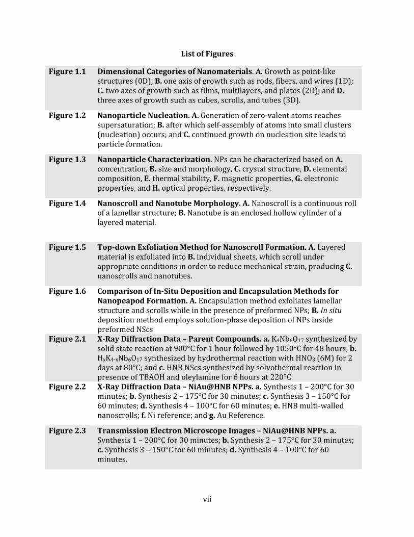
List of Figures
Figure 1.1 Dimensional Categories of Nanomaterials. A. Growth as point-like structures (0D); B. one axis of growth such as rods, fibers, and wires (1D); C. two axes of growth such as films, multilayers, and plates (2D); and D. three axes of growth such as cubes, scrolls, and tubes (3D).
Figure 1.2 Nanoparticle Nucleation. A. Generation of zero-valent atoms reaches supersaturation; B. after which self-assembly of atoms into small clusters (nucleation) occurs; and C. continued growth on nucleation site leads to particle formation.
Figure 1.3 Nanoparticle Characterization. NPs can be characterized based on A. concentration, B. size and morphology, C. crystal structure, D. elemental composition, E. thermal stability, F. magnetic properties, G. electronic properties, and H. optical properties, respectively.
Figure 1.4 Nanoscroll and Nanotube Morphology. A. Nanoscroll is a continuous roll of a lamellar structure; B. Nanotube is an enclosed hollow cylinder of a layered material.
Figure 1.5 Top-down Exfoliation Method for Nanoscroll Formation. A. Layered material is exfoliated into B. individual sheets, which scroll under appropriate conditions in order to reduce mechanical strain, producing C. nanoscrolls and nanotubes.
Figure 1.6 Comparison of In-Situ Deposition and Encapsulation Methods for
Nanopeapod Formation. A. Encapsulation method exfoliates lamellar structure and scrolls while in the presence of preformed NPs; B. In situ deposition method employs solution-phase deposition of NPs inside preformed NScs
Figure 2.1 X-Ray Diffraction Data – Parent Compounds. a. K4Nb6O17 synthesized by solid state reaction at 900°C for 1 hour followed by 1050°C for 48 hours; b. HxK4-xNb6O17 synthesized by hydrothermal reaction with HNO3 (6M) for 2 days at 80°C; and c. HNB NScs synthesized by solvothermal reaction in presence of TBAOH and oleylamine for 6 hours at 220°C
Figure 2.2 X-Ray Diffraction Data – NiAu@HNB NPPs. a. Synthesis 1 – 200°C for 30 minutes; b. Synthesis 2 – 175°C for 30 minutes; c. Synthesis 3 – 150°C for 60 minutes; d. Synthesis 4 – 100°C for 60 minutes; e. HNB multi-walled nanoscrolls; f. Ni reference; and g. Au Reference.
Figure 2.3 Transmission Electron Microscope Images – NiAu@HNB NPPs. a. Synthesis 1 – 200°C for 30 minutes; b. Synthesis 2 – 175°C for 30 minutes; c. Synthesis 3 – 150°C for 60 minutes; d. Synthesis 4 – 100°C for 60 minutes.

viii
Figure 2.4 Elemental Dispersive Spectroscopy Data – NiAu@HNB NPPs. a. Synthesis 1 – 200°C for 30 minutes, first area of sample; b. Synthesis 1 – 200°C for 30 minutes, second area of sample.
Figure 2.5 Quantitative Elemental Composition – NiAu@HNB NPPs. Quantitative calculations of both areas in Synthesis 1 yielded a weight percent ratio of 0.04% Ni to 0.01% Au.

ix
List of Tables
Table 2.1 Reaction Conditions – In Situ Deposition of NiAu@HNB NPPs
Table 2.2 HNB NScs XRD Reflections
x
Abstract An in situ deposition procedure was developed for the nanopeapod (NPP) formation
of NiAu nanoparticles inside preformed acid-exchanged hexaniobate nanoscrolls (HNB).
Metal salt precursors of Ni(acac)2 and HAuCl4∙3H2O were reduced in solution under mild
synthetic conditions in the presence of the preformed acid-exchanged hexaniobate
nanoscrolls. Two of the surfactants used for the formation of the nanoparticles were
oleylamine and triphenylphosphine oxide (TTPO). Reaction conditions were studied and
modified to produce well-defined NiAu@HNB NPP systems, with monodispersed particles
evenly filling and orienting within the nanoscrolls. The synthetic parameters studied were
both time and temperature, with the most well-defined peapod systems being those
produced from lower temperatures (100°C) and longer reaction times (60 minutes).
NiAu@HNB NPPs synthesized under these conditions yielded a narrow size distribution of
NiAu nanoparticles, ranging ~ 4 – 10 nm in diameter, evenly filled and oriented within the
inner diameter of hexaniobate nanoscrolls (ranging ~2 μm in length).
Keywords: Nanoscrolls, Hexaniobate, Nanopeapods, Ni-Au, In-Situ Deposition
Chapter 1
Introduction
1.1 Nanomaterial Fundamentals: Dimensional Growth
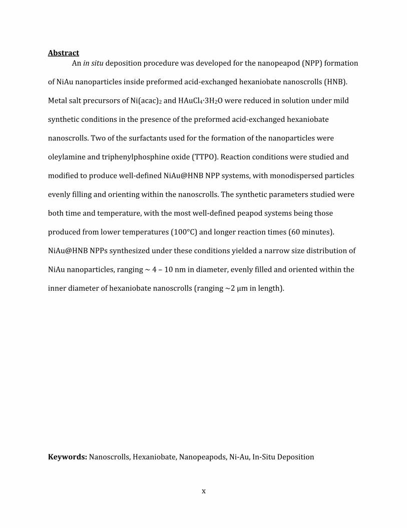
Throughout the scope of chemical applications and study, the class of nanomaterials
is a substantial field that is ever developing. In nanomaterials alone, there are basic
categories which define the nano
defined by dimensionality in which the component is made, as shown in
Spheres, clusters, and particles are 0D, where these grow as point
fibers, wires, scrolls, and tubes,
materials. Upon adding another dimension of growth, like that of films, multilayers,
or sheets, the material becomes 2D. Lastly, nanomaterials consisting
growth such as cubes, flowers and other polycrystals
Figure 1.1: Dimensional Categories of Nanomaterials
of growth such as rods, fibers, wires, scrolls, and
and plates (2D); and D. three axes of growth such as cubes(3D).
1
Nanomaterial Fundamentals: Dimensional Growth
hout the scope of chemical applications and study, the class of nanomaterials
is a substantial field that is ever developing. In nanomaterials alone, there are basic
categories which define the nano-sized material itself. Most commonly, nanomaterials are
defined by dimensionality in which the component is made, as shown in Figure 1
particles are 0D, where these grow as point-like structures. R
scrolls, and tubes, which grow along one dimension such as length, are 1D
materials. Upon adding another dimension of growth, like that of films, multilayers,
the material becomes 2D. Lastly, nanomaterials consisting of multiple
, flowers and other polycrystals are considered 3D [1].
: Dimensional Categories of Nanomaterials. A. Growth as point-like structures (0D);
, scrolls, and tubes (1D); C. two axes of growth such as films, multilayers,
three axes of growth such as cubes(3D).
hout the scope of chemical applications and study, the class of nanomaterials
is a substantial field that is ever developing. In nanomaterials alone, there are basic
sized material itself. Most commonly, nanomaterials are
Figure 1.1.
like structures. Rods,
which grow along one dimension such as length, are 1D
materials. Upon adding another dimension of growth, like that of films, multilayers, plates,
of multiple axes
are considered 3D [1].
like structures (0D); B. one axis
two axes of growth such as films, multilayers,
2
1.2 Nanoparticles: Structural Characteristics
Nanoparticles themselves are considered 0D materials, in that the growth of the
particles occurs from a point-like origin and continues outward in all directions.
Nanoparticle (NP) is defined as a particle of any shape with dimensions of 10-9 – 10-7 m.
NPs behave as a whole unit, thereby possessing novel physical characteristics when
compared to the bulk material [2]. Physical properties of NPs are related to the
composition and morphology of the structure, but some of the foremost properties include
unusual electron transport, enhanced quantum yields, functionalization capabilities, and
stronger magnetic response in some materials. These properties are most often a result of
the large surface area of exposed atoms relative to the volume of the material. Commonly
synthesized NPs include metal chalcogenides, transition metals, metal oxides, and noble
metals, to name a few. By combining various classes of NPs, synergistic properties can be
realized and used in a wide variety of applications, from biomedical practice, to optical and
electronic fields, to environmental and industrial uses.
Synthetic strategies for NPs are divided into two categories, like all nanomaterials:
the top-down method and the bottom-up method. In the top-down method, particles are
formed by the breakdown of bulk material. Top-down techniques include ball milling,
sonication, and other break-down methods. While these syntheses offer the benefit of bulk
processing for nanomaterial formation, the resulting particles are typically unevenly
distributed in size and shape.
Bottom-up approaches build NPs from the atomic level upwards. This allows for
more control over size, shape, and morphology, although the yield can often be relatively
low. Bottom-up approaches to NP synthesis are subdivided into liquid
phase. The most common liquid
reduction, hydrothermal/solvothermal synthesis, precipitation, co
processing, microwave synthesis, sonochemical synthesis, and electrochemica
assisted synthesis. Whereas gas
precursor evaporation and pyrolysis, laser
microwave plasma, sputtering, laser ablation, and droplet evaporation and
The growth mechanism for liquid
solid nanomaterial in solution. Typically, a precursor is reduced or decomposed in solution
to yield zero-valent atoms. Nucleation is the point at which
minimum concentration for supersaturation, and they then begin to self
small clusters. The point of supersaturation is essentially the driving force for nucleation to
begin. Further growth from zero
of particles, which can occur through Ostwald ripening or by oriented attachment [4].
Figure 1.2: Nanoparticle Nucleation.
which self-assembly of atoms into small clusters (nucleation) occurs; and
site leads to particle formation.
3
up approaches to NP synthesis are subdivided into liquid-phase and
phase. The most common liquid-phase methods include many different strategies, such as:
reduction, hydrothermal/solvothermal synthesis, precipitation, co-precipitation, sol
processing, microwave synthesis, sonochemical synthesis, and electrochemica
assisted synthesis. Whereas gas-phase methods include chemical vapor deposition,
precursor evaporation and pyrolysis, laser-induced evaporation and pyrolysis, thermal and
microwave plasma, sputtering, laser ablation, and droplet evaporation and explosion [3].
The growth mechanism for liquid-phase synthesized NPs is based on the nucleation of the
solid nanomaterial in solution. Typically, a precursor is reduced or decomposed in solution
valent atoms. Nucleation is the point at which these atoms are at the
minimum concentration for supersaturation, and they then begin to self-accumulate into
small clusters. The point of supersaturation is essentially the driving force for nucleation to
begin. Further growth from zero-valent atoms on this nucleation site yields the formation
of particles, which can occur through Ostwald ripening or by oriented attachment [4].
2: Nanoparticle Nucleation. A. Generation of zero-valent atoms reaches supersaturation;
atoms into small clusters (nucleation) occurs; and C. continued growth on nucleation
phase and gas-
phase methods include many different strategies, such as:
precipitation, sol-gel
processing, microwave synthesis, sonochemical synthesis, and electrochemical template-
phase methods include chemical vapor deposition,
induced evaporation and pyrolysis, thermal and
explosion [3].
phase synthesized NPs is based on the nucleation of the
solid nanomaterial in solution. Typically, a precursor is reduced or decomposed in solution
these atoms are at the
accumulate into
small clusters. The point of supersaturation is essentially the driving force for nucleation to
is nucleation site yields the formation
of particles, which can occur through Ostwald ripening or by oriented attachment [4].
valent atoms reaches supersaturation; B. after
continued growth on nucleation

Figure 1.2 describes the proce
growth of the NPs can occur through Ostwald ripening or by oriented attachment. In the
case of Ostwald ripening, the mechanism for crystal coarsening has been described in
terms of growth of large particles at the expense of smaller particle
typically occurs when supersaturation is low. Alternatively, oriented attachment is
considered the self-organization of particles with a common crystallographic orientation,
thereby eliminating two high-energy surfaces by crystallograp
characterization methods employed for synthesized NPs vary based on the material’s
composition, which itself can differ widely according to desired needs. Most of the
significant methods used are those that analyze size, morphology, and
elemental composition; optical, electronic, and magnetic properties; crystal structure and
even thermal stability, to name a few. A schematic for NP characterization is shown in
Figure 1.3.
Figure 1.3: Nanoparticle Characterization.
morphology, C. crystal structure, D. elemental composition,
electronic properties, and H. optical properties, respectively.
4
2 describes the process of NP nucleation and growth. After nucleation,
growth of the NPs can occur through Ostwald ripening or by oriented attachment. In the
case of Ostwald ripening, the mechanism for crystal coarsening has been described in
terms of growth of large particles at the expense of smaller particles. Ostwald ripening
typically occurs when supersaturation is low. Alternatively, oriented attachment is
organization of particles with a common crystallographic orientation,
energy surfaces by crystallographic fusion [5]. The
characterization methods employed for synthesized NPs vary based on the material’s
composition, which itself can differ widely according to desired needs. Most of the
significant methods used are those that analyze size, morphology, and topography;
elemental composition; optical, electronic, and magnetic properties; crystal structure and
even thermal stability, to name a few. A schematic for NP characterization is shown in
3: Nanoparticle Characterization. NPs can be characterized based on A. concentration,
elemental composition, E. thermal stability, F. magnetic properties,
optical properties, respectively.
er nucleation,
growth of the NPs can occur through Ostwald ripening or by oriented attachment. In the
case of Ostwald ripening, the mechanism for crystal coarsening has been described in
s. Ostwald ripening
typically occurs when supersaturation is low. Alternatively, oriented attachment is
organization of particles with a common crystallographic orientation,
hic fusion [5]. The
characterization methods employed for synthesized NPs vary based on the material’s
composition, which itself can differ widely according to desired needs. Most of the
topography;
elemental composition; optical, electronic, and magnetic properties; crystal structure and
even thermal stability, to name a few. A schematic for NP characterization is shown in
concentration, B. size and
magnetic properties, G.
Conventional microscopy techn
transmission electron microscopy (TEM), scanning electron microscopy (SEM), and atomic
force microscopy (AFM). Furthermore, Raman, UV
elemental dispersive (EDS) spectroscopy
compositional and quantitative measures. Dynamic light scattering (DLS) is used to
measure optical scattering properties; cyclic and linear sweep voltammetry are used to
analyze electronic properties; thermal stabili
thermogravimetric analysis (TGA) and differential scanning calorimetry (DSC); and
vibrating sample magnetometer (VSM) and superconducting quantum interference device
(SQUID) are employed for studies of magnetic properties
that this list is not a limit of characterization methods used for NP analysis.
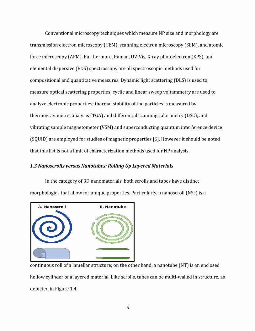
1.3 Nanoscrolls versus Nanotubes: Rolling Up Layered Materials
In the category of 3D nanomaterials, both scrolls and tubes have distinct
morphologies that allow for unique properties. Particularly, a nanoscroll (NS
continuous roll of a lamellar structure; on the other hand, a nanotube (NT) is an enclosed
hollow cylinder of a layered material.
depicted in Figure 1.4.
5
Conventional microscopy techniques which measure NP size and morphology are
transmission electron microscopy (TEM), scanning electron microscopy (SEM), and atomic
force microscopy (AFM). Furthermore, Raman, UV-Vis, X-ray photoelectron (XPS), and
elemental dispersive (EDS) spectroscopy are all spectroscopic methods used for
compositional and quantitative measures. Dynamic light scattering (DLS) is used to
measure optical scattering properties; cyclic and linear sweep voltammetry are used to
analyze electronic properties; thermal stability of the particles is measured by
thermogravimetric analysis (TGA) and differential scanning calorimetry (DSC); and
vibrating sample magnetometer (VSM) and superconducting quantum interference device
(SQUID) are employed for studies of magnetic properties [6]. However it should be noted
that this list is not a limit of characterization methods used for NP analysis.
Nanoscrolls versus Nanotubes: Rolling Up Layered Materials
In the category of 3D nanomaterials, both scrolls and tubes have distinct
morphologies that allow for unique properties. Particularly, a nanoscroll (NS
continuous roll of a lamellar structure; on the other hand, a nanotube (NT) is an enclosed
hollow cylinder of a layered material. Like scrolls, tubes can be multi-walled i
iques which measure NP size and morphology are
transmission electron microscopy (TEM), scanning electron microscopy (SEM), and atomic
ray photoelectron (XPS), and
are all spectroscopic methods used for
compositional and quantitative measures. Dynamic light scattering (DLS) is used to
measure optical scattering properties; cyclic and linear sweep voltammetry are used to
ty of the particles is measured by
thermogravimetric analysis (TGA) and differential scanning calorimetry (DSC); and
vibrating sample magnetometer (VSM) and superconducting quantum interference device
[6]. However it should be noted
In the category of 3D nanomaterials, both scrolls and tubes have distinct
morphologies that allow for unique properties. Particularly, a nanoscroll (NSc) is a
continuous roll of a lamellar structure; on the other hand, a nanotube (NT) is an enclosed
walled in structure, as
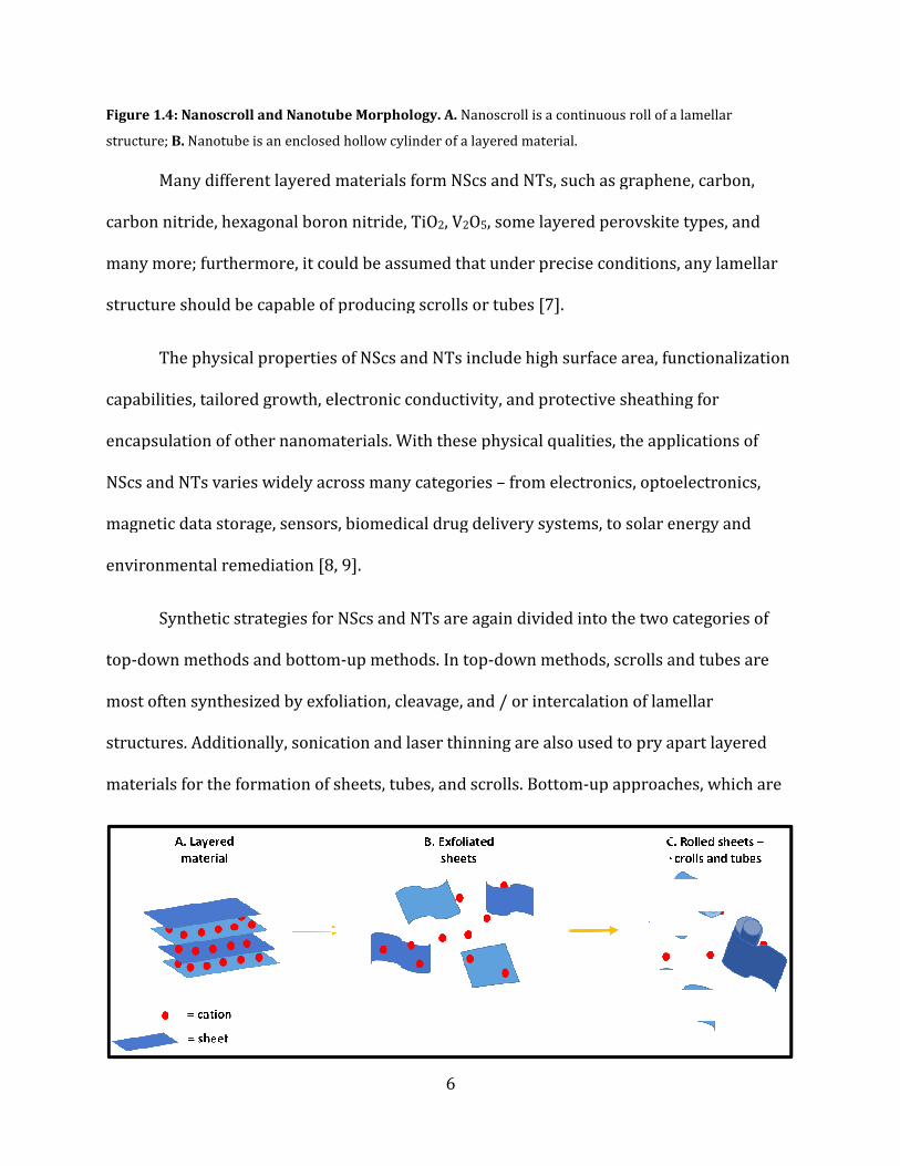
Figure 1.4: Nanoscroll and Nanotube Morphology.
structure; B. Nanotube is an enclosed hollow cylinder of a layered material.
Many different layered materials form
carbon nitride, hexagonal boron nitride, TiO
many more; furthermore, it could be assumed that under precise conditions, any lamellar
structure should be capable of producing
The physical properties of
capabilities, tailored growth, electronic conductivity, and protective sheathing for
encapsulation of other nanomaterials. With these physical quali
NScs and NTs varies widely across many categories
magnetic data storage, sensors, biomedical drug delivery systems, to solar energy and
environmental remediation [8, 9].
Synthetic strategies for
top-down methods and bottom
most often synthesized by exfoliation, cleavage, and / or intercalation of lamellar
structures. Additionally, sonication and laser thinning are also used to pry apart layered
materials for the formation of sheets, tubes, and scrolls. Bottom
6
4: Nanoscroll and Nanotube Morphology. A. Nanoscroll is a continuous roll of a lamellar
Nanotube is an enclosed hollow cylinder of a layered material.
Many different layered materials form NScs and NTs, such as graphene, carbon,
carbon nitride, hexagonal boron nitride, TiO2, V2O5, some layered perovskite types, and
urthermore, it could be assumed that under precise conditions, any lamellar
structure should be capable of producing scrolls or tubes [7].
The physical properties of NScs and NTs include high surface area, functionalization
capabilities, tailored growth, electronic conductivity, and protective sheathing for
encapsulation of other nanomaterials. With these physical qualities, the applications of
and NTs varies widely across many categories – from electronics, optoelectronics,
magnetic data storage, sensors, biomedical drug delivery systems, to solar energy and
environmental remediation [8, 9].
or NScs and NTs are again divided into the two categories of
down methods and bottom-up methods. In top-down methods, scrolls and tubes are
most often synthesized by exfoliation, cleavage, and / or intercalation of lamellar
nication and laser thinning are also used to pry apart layered
materials for the formation of sheets, tubes, and scrolls. Bottom-up approaches, which are
Nanoscroll is a continuous roll of a lamellar
and NTs, such as graphene, carbon,
perovskite types, and
urthermore, it could be assumed that under precise conditions, any lamellar
high surface area, functionalization
capabilities, tailored growth, electronic conductivity, and protective sheathing for
ties, the applications of
from electronics, optoelectronics,
magnetic data storage, sensors, biomedical drug delivery systems, to solar energy and
and NTs are again divided into the two categories of
down methods, scrolls and tubes are
most often synthesized by exfoliation, cleavage, and / or intercalation of lamellar
nication and laser thinning are also used to pry apart layered
up approaches, which are
7
not as commonly utilized, include solution phase growth, chemical vapor deposition, and
electron beam lithography. While not typically employed, these approaches may afford
more control over the morphology and topography of sheets, tubes, and scrolls. Figure 1.5
illustrates the top-down synthetic approach for NScs and NTs [10].
Figure 1.5: Top-down Exfoliation Method for Nanoscroll Formation. A. Layered material is exfoliated into
B. individual sheets, which scroll under appropriate conditions in order to reduce mechanical strain,
producing C. nanoscrolls and nanotubes.
After formation of NScs and NTs, common characterization techniques used are
TEM, SEM, and AFM for determination of morphology and topography, XRD for crystal
structure analysis, and Raman spectroscopy, UV-Vis spectroscopy, XPS, and EDS for
composition and quantitative measures [10].
1.4 Nanopeapod Formation: Inclusion of Nanoparticles within Nanoscrolls
Due to the enclosed nature of NScs, they can provide sheathing and support for
other nanomaterials, such as quantum dots, particles, or even wires and rods. Additionally,
the inclusion of NPs offers additional physical properties and molecular functionalities
[11]. The architectural combination of NPs inside of a NSc is known as a nanopeapod
(NPP). This ordered arrangement can provide both mechanical and chemical stability while
fostering NP and NSc interactions. The cooperative properties of the NPP is a result of the
geometric assembly of the building units in addition to the intrinsic properties of each
component [11]. The designed interface between the different components can produce
novel features and properties, such as unusual electron transport, improved quantum
yields, functionalization capabilities, and even stronger magnetic response in some
materials [11].

8
As such, the geometry of the NPP composite structure affords numerous
fundamental and practical applications in catalytic processes [12], magnetic data storage
[13], optical devices, sensors [14], and templates [15] for other assemblies.
Previous syntheses for the preparation of NPPs have included microwave reactions
[16], pulsed electrodeposition in combination with solid state reaction [17], pulsed liquid-
injection with chemical vapor deposition [18], vapor–liquid–solid growth [19], Rayleigh-
instability induced encapsulation via atomic layer deposition [20], wet-chemical method by
selective etching [21], electrodeposition inside preformed nanotubes [22], Galvanic
displacement of electrodeposited multi-segmented nanowires [23], and sacrificial template
route [24].
While these synthetic approaches for NPPs are effective in terms of morphological
control, phase purity, and crystallinity, combining NPs within NScs in a well-defined
manner is not always clear-cut [11]. Difficulties remain in the synthetic strategies for
precise control over NPPs with monodisperse particles evenly filling and orienting within
the scrolls. Additionally, some of these previously listed methods can be costly, tedious, and
not easily employed in bulk synthesis.
Other methods such as encapsulation and in situ deposition, as previously reported
by our group [11, 15, 26, 27], allow for more precise control in the synthesis of NPPs. In the
encapsulation method, the lamellar structure is pulled apart (exfoliated) into sheets and
scrolled while in the presence of preformed NPs. This allows for the capture of the NPs into
the rolled interior of the NSc. Alternatively, in situ deposition involves the solution-phase
deposition of NPs inside preformed NScs. The in situ method also produces NPs in the inner

diameter of NScs. Figure 1.6 shows both mechanisms for the encapsulation and
deposition methods for the synthesis of NPPs.
Figure 1.6: Comparison of In-Situ Deposition and Encapsulation Methods for Nanopeapod Formation.
A. Encapsulation method exfoliates lamellar structure
In situ deposition method employs solution
Building on previous methods
mild protocol for the synthesis of NPP composites was developed using an
deposition method. During this wet synthesis, preformed hexaniobate (HNB)
treated with metal salt precursors of Ni and Au
in solution under mild synthetic conditions in the presence of oleylamine and
triphenylphosphine oxide to form NPP systems.
The objective in synthesizing
preformed HNB NScs was to obtain well
Another overlying goal behind the development of this method is that essentially if any
9
6 shows both mechanisms for the encapsulation and
deposition methods for the synthesis of NPPs.
Situ Deposition and Encapsulation Methods for Nanopeapod Formation.
Encapsulation method exfoliates lamellar structure and scrolls while in the presence of preformed NPs;
deposition method employs solution-phase deposition of NPs inside preformed NScs
Building on previous methods reported by our group [11, 15, 26, 27]
mild protocol for the synthesis of NPP composites was developed using an in situ
deposition method. During this wet synthesis, preformed hexaniobate (HNB)
etal salt precursors of Ni and Au; subsequently the precursors
in solution under mild synthetic conditions in the presence of oleylamine and
triphenylphosphine oxide to form NPP systems.
The objective in synthesizing ferromagnetic and noble metal composite NPs inside
was to obtain well-defined and monodisperse nanocomposites.
Another overlying goal behind the development of this method is that essentially if any
6 shows both mechanisms for the encapsulation and in situ
Situ Deposition and Encapsulation Methods for Nanopeapod Formation.
and scrolls while in the presence of preformed NPs; B.
NScs.
[11, 15, 26, 27], a facile and
in situ
deposition method. During this wet synthesis, preformed hexaniobate (HNB) NScs were
; subsequently the precursors were reduced
in solution under mild synthetic conditions in the presence of oleylamine and
composite NPs inside
defined and monodisperse nanocomposites.
Another overlying goal behind the development of this method is that essentially if any

10
reduction method of NPs can be grown in solution, HNB NScs could serve as a template for
chain growth of said NPs to form NPPs. The realization of this goal can lead to the
combination of many different compounds, where the properties of the nanomaterials can
be tailored to suit desired requirements.
Reaction conditions were studied and modified to produce well-defined NiAu@HNB
NPP systems, with monodispersed particles evenly filling and orienting within the NScs.
The synthetic parameters studied were both time and temperature, with the most well-
defined peapod systems being those produced from lower temperatures (100°C) and
longer reaction times (60 minutes).

11
1.5 References:
[1] Ngo, C. & Van De Voorde, M. Nanotechnology in a Nutshell. 2014, 4, 67-82.
[2] Vert, M., Doi, Y., Hellwich, K. H., Hess, M., Hodge, P., Kubisa, P., Rinaudo, M., & Schué, F.
Pure Appl. Chem. 2012, 84(2), 377–410.
[3] Kruis, F.E., Fissan, H., Peled, A. J. Aerosol Sci. 1998, 29(5-6), 511-535.
[4] Cushing, B.L., Kolesnichenko, V. L., & O’Connor, C. J. Chem. Rev. 2004, 104, 3893-3946.
[5] van Huis, M. A., Kunneman, L. T., Overgaag, K., Xu, Q., Pandraud, G., Zandbergen, H. W., &
Vanmaekelbergh, D. Nano Lett. 2008, 8(11), 3959-3963.
[6] Chaudhuri, R. G. & Paria, S. Chem. Rev. 2012, 112, 2373–2433.
[7] Geim, A. & Grigorieva, I. Nature. 2013, 499, 419-425.
[8] Joshi, R. & Schneider, J. Chem. Soc. Rev. 2012, 41, 5285-5312.
[9] Wang, Z. L. J. Mater. Chem. 2009, 19, 826-827.
[10] Huang, X., Zenga, Z., & Zhang, H.; Chem. Soc. Rev. 2013, 13(42), 1934-1946.
[11] Adireddy, S., Carbo, C. E., Yao, Y., Vargas, J. M., Spinu, L., & Wiley, J. B. Chem. Mater.
2013, 25, 3902−3909.
[12] (a) Kudo, A., Tanaka, A., Domen, K., Maruya, K., Aika, K., & Onishi, T. J. Catal. 1988, 111,
67-76. (b) Zou, Z., Ye, J., Sayama, K., & Arakawa, H. Nature. 2001, 414, 625-627. (c) Zengab,
T., Chena, W., Cirtiua, C. M., Mooresa, A., Song, G., & Li, C. J. Green Chem. 2010, 12, 570-573.
[13] Lal, S., Link, S., & Halas, N. J. Nat. Photonics. 2007, 1, 641-648.
[14] Kong, J., Franklin, N. R, Zhou, C., Chapline, M. G., Peng, S., Cho, K., Dai, H. J. Science.
2000, 287, 622-625.
[15] Yao, Y., Chaubey, G. S., & Wiley, J. B. J. Am. Chem. Soc. 2012, 134, 2450-2452.
12
[16] Hu, M., Chen, H., Shen, C., Hong, L., Huang, B., Chen, K., & Chen, L. Nat. Mater. 2006, 5,
102-106.
[17] Liu, L., Lee, W., Scholz, R., Pippel, E., & Gösele, U. Angew. Chem. Int. Ed. 2008, 47, 7004 –
7008.
[18] Zhou, W., Wang, J., Gong, Z., Gong, J., Qi, N., & Wang, B. Appl. Phys. Lett. 2009, 94,
022904.
[19] Zhou, W., Sun, L., Yu, T., Zhang, J., Gong, H., Fan, H. Nanotechnology. 2009, 20, 455603.
[20] Qin, Y., Lee, S. M., Pan, A., Gösele, U., & Knez, M. Nano Lett. 2008, 8(1), 114–118.
[21] Sioss, J. & Keating, C. Nano Lett. 2005, 5(9), 1779–1783.
[22] Zhu, W., Wang, G., Hong, X., Shen, X., Li, D., Xie, X. Electrochimica Acta. 2009, 55(2),
480–484.
[23] Hangarter, C. M., Lee, Y., Hernandez, S.C., Choa, Y., and Myung, N. V. Angew. Chem. Int.
Ed. 2010, 49(39), 7081–7085.
[24] Zhou, W., Chen, W., Nai, J., Yin, P., Chen, C., Guo, L. Adv. Funct. Mater. 2010, 20(21),
3678–3683.
[25] Adireddy, S., Carbo, C. E., Rostamzadeh, T., Vargas, J. M., Spinu, L., & Wiley, J. B., Angew.
Chem. Int. Ed. 2014, 53, 4614 –4617.
[26] Adireddy, S., Rostamzadeh, T., Carbo, C. E., & Wiley, J. B. Langmuir. 2015, 31, 480−485.

13
Chapter 2
Synthesis of Ni-Au@HNB NPPs: In Situ Deposition in Preformed Nanoscrolls
2.1 Introduction
In situ growth methods have been established in our group for the fabrication of
NPPs with pure gold NPs deposited in preformed HNB NScs [4]. There is also an interest in
preparing materials by this approach that exhibit magnetic properties. The objective was
then to fabricate ferromagnetic and noble metal composite NPs inside preformed HNB
NScs. Such materials would be of interest in applications as anisotropic magnetic
components [9], photocatalytic composites [8], and possibly as biomedical devices [10].
Herein methods for the fabrication of NiAu@HNB NPP with well-defined NPs are
presented.
2.2 Experimental
2.2.1 Solid State Synthesis of K4Nb6O17
Potassium hexaniobate was synthesized according to the procedure as reported
previously by our group [1]. K4Nb6O17 was synthesized by the solid state reaction of K2CO3
and Nb2O5, in the molar ratio of 1.0:1.4. The starting materials were ground and pre-heated
together in an alumina crucible at 900°C for 1 hour, after which the reaction was ground
again intermittently. The reaction was then heated again at 1050°C for 48 hours. The
resultant white powder of K4Nb6O17 was washed multiple times with DI water and ethanol,
and it was allowed to dry overnight in an oven at 75°C. The crystal structure of K4Nb6O17
was then characterized by powder X-ray diffraction (XRD).
14
2.2.2 Hydrothermal Synthesis of HxK4-xNb6O17
Acid-exchanged K4Nb6O17 (HxK4-xNb6O17) was obtained by treating 1.0 g of K4Nb6O17
with 8 mL HNO3 (6M). The solution was placed in a Teflon liner inside of a stainless-steel
autoclave, which was heated at 80°C for 2 days. The product was washed multiple times
with DI water and ethanol, and it was allowed to dry overnight in an oven at 75°C. The
crystal structure of HxK4-xNb6O17 was then characterized by XRD.
2.2.3 Solvothermal Synthesis of Multi-Walled Nanoscrolls (NScs)
Hexaniobate nanoscrolls (HNB NScs) were synthesized by a method as reported
previously by our group [2]. First, 0.1g of HxK4-xNb6O17 was added to 0.15 g (0.19 mmol)
TBAOH, 5 mL oleylamine (~15 mmol), and 8 mL toluene. The solution mixture was allowed
to stir magnetically for 1 hour in a Teflon liner, which was then transferred to a stainless-
steel autoclave. The autoclave was heated at 220°C for 6 hours, and then it was allowed to
cool to room temperature. The product of HNB NScs was washed with ethanol several
times, and it was allowed to dry overnight in an oven at 75°C. The dried sample was then
characterized by XRD.
2.2.4 In Situ Deposition of NiAu@HNB Nanopeapods (NPPs)
The nanopeapods were synthesized through the in situ deposition of Ni and Au
precursors in preformed hexaniobate nanoscrolls, by methods adapted from the literature
[3, 4]. First, 0.128 g (0.5 mmol) of Ni(acac)2 and 0.083 g (0.3 mmol) of triphenylphosphine
oxide were dissolved in 7mL of oleylamine by stirring the mixture at 45°C. The resulting Ni
mixture produced a viscous green solution that became less opaque upon dissolution.
15
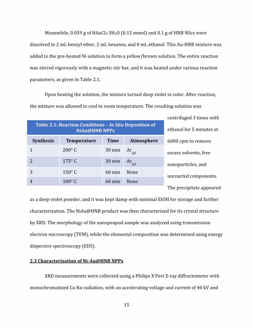
Meanwhile, 0.059 g of HAuCl4∙3H2O (0.15 mmol) and 0.1 g of HNB NScs were
dissolved in 2 mL benzyl ether, 2 mL hexanes, and 8 mL ethanol. This Au-HNB mixture was
added to the pre-heated Ni solution to form a yellow/brown solution. The entire reaction
was stirred vigorously with a magnetic stir bar, and it was heated under various reaction
parameters, as given in Table 2.1.
Upon heating the solution, the mixture turned deep violet in color. After reaction,
the mixture was allowed to cool to room temperature. The resulting solution was
centrifuged 3 times with
ethanol for 5 minutes at
6000 rpm to remove
excess solvents, free
nanoparticles, and
unreacted components.
The precipitate appeared
as a deep violet powder, and it was kept damp with minimal EtOH for storage and further
characterization. The NiAu@HNB product was then characterized for its crystal structure
by XRD. The morphology of the nanopeapod sample was analyzed using transmission
electron microscopy (TEM), while the elemental composition was determined using energy
dispersive spectroscopy (EDS).
2.3 Characterization of Ni-Au@HNB NPPs
XRD measurements were collected using a Philips X’Pert X-ray diffractometer with
monochromatized Cu Kα radiation, with an accelerating voltage and current of 40 kV and
Table 2.1: Reaction Conditions – In Situ Deposition of
NiAu@HNB NPPs
Synthesis Temperature Time Atmosphere
1 200° C 30 min Ar(g)
2 175° C 30 min Ar(g)
3 150° C 60 min None
4 100° C 60 min None
16
40 mA. The morphology of the nanopeapods was analyzed using a JEOL 2010 TEM at an
accelerating voltage of 200kV, equipped with a Gatan CCD camera. EDAX Genesis EDS (used
concurrently with TEM) was used to measure the elemental composition of the samples.
2.4 Results
2.4.1 Synthesis of K4Nb6O17 and HxK4-xNb6O17
Potassium hexaniobate was synthesized through a solid state reaction by the
grinding of K2CO3 and Nb2O5 (molar ratio of 1.0 to 1.4), followed by pre-heating at 900°C
for 1 hour. The reaction mixture was then intermediately ground, and replaced in the
furnace at 1050°C for 48 hours. The white powder of K4Nb6O17 was allowed to cool to room
temperature. It was washed with DI water and ethanol in order to remove any unreacted
materials, and it was then allowed to dry overnight in a drying oven (75°C). The product
was characterized by XRD, as given below in Figure 2.1a. The prominent (040) reflection of
K4Nb6O17 appeared at 9.5° two theta, while characteristic reflections of (220) at 23.2°,
(002) at 27.8°, (0 10 0) at 31.8°, and (400) at 46.6° are also seen. Weaker reflections of
(0k0) appeared, with (020) at 4.8˚ and (060) at 14.3˚ 2theta.
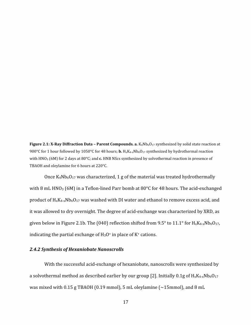
Figure 2.1: X-Ray Diffraction Data –
900°C for 1 hour followed by 1050°C
with HNO3 (6M) for 2 days at 80°C; and
TBAOH and oleylamine for 6 hours at 220°C.
Once K4Nb6O17 was characterized,
with 8 mL HNO3 (6M) in a Teflon
product of HxK4-xNb6O17 was washed with DI water and ethanol to remove excess acid, and
it was allowed to dry overnight. The degree of acid
given below in Figure 2.1b. The (040) reflection shifted from 9.5° to 11.1° for H
indicating the partial exchange of H
2.4.2 Synthesis of Hexaniobate Nanoscrolls
With the successful acid
a solvothermal method as described
was mixed with 0.15 g TBAOH
17
– Parent Compounds. a. K4Nb6O17 synthesized by solid state reaction at
followed by 1050°C for 48 hours; b. HxK4-xNb6O17 synthesized by hydrothermal reaction
(6M) for 2 days at 80°C; and c. HNB NScs synthesized by solvothermal reaction in presence of
TBAOH and oleylamine for 6 hours at 220°C.
was characterized, 1 g of the material was treated hydrothermally
(6M) in a Teflon-lined Parr bomb at 80°C for 48 hours. The acid
was washed with DI water and ethanol to remove excess acid, and
it was allowed to dry overnight. The degree of acid-exchange was characterized by X
1b. The (040) reflection shifted from 9.5° to 11.1° for H
indicating the partial exchange of H3O+ in place of K+ cations.
Synthesis of Hexaniobate Nanoscrolls
With the successful acid-exchange of hexaniobate, nanoscrolls were synthesized by
as described earlier by our group [2]. Initially 0.1g of H
(0.19 mmol), 5 mL oleylamine (~15mmol), and 8 mL
synthesized by solid state reaction at
synthesized by hydrothermal reaction
synthesized by solvothermal reaction in presence of
hydrothermally
lined Parr bomb at 80°C for 48 hours. The acid-exchanged
was washed with DI water and ethanol to remove excess acid, and
exchange was characterized by XRD, as
1b. The (040) reflection shifted from 9.5° to 11.1° for HxK4-xNb6O17,
anoscrolls were synthesized by
0.1g of HxK4-xNb6O17
, and 8 mL

18
toluene. The reaction was stirred for 1 hour to ensure mixing and dissolution, then the
reaction was transferred to a Teflon-lined Parr-bomb. The reaction was heated at 220°C for
6 hours, allowed to cool to room temperature, and washed with ethanol. The HNB NScs
were then dried overnight, and the product was characterized by XRD as shown in Figure
2.1c. The product was assigned reflections based on previous literature results [5]. The
presence of multiple low-angle peaks between 3° – 12° 2theta indicated the scrolled nature
of the original HxK4-xNb6O17. These 4 peaks could relate to the (0k0) reflections that are
common to the parent compound of K4Nb6O17. A broad (040) reflection appeared at ~9.7°,
which would relate to d040 = 9.1Å. Other broad low-angle reflections are seen at ~4.7° and
~6.8°, either of which could possibly relate to the (020) reflection. While another broad
low-angle reflection is seen at 11.1°, this reflection may also be related to the (060). A weak
(220) reflection is seen at ~23.2°, while a sharp reflection of (002) is seen at ~27.8°, and
the (400) reflection appeared at 46.6° 2theta.
2.4.3 In Situ Deposition of NiAu Nanoparticles in Preformed Hexaniobate Nanoscrolls

The NiAu@HNB NPPs were synthesized under various reaction conditions, as listed
in Table 2.1, from a modified literature procedure
2.2a-d, again showed the low-angle reflections common to
the measurements also showed
~38.1°. The peak seen at 38.1° relates to Au (111),
both Au (200) and Ni (111). However, there is no peak seen for the Ni (200)
could be inferred at 76.5° 2theta
relate to both Au (311) and Ni (220). XRD data confirms the crystal structure of at
metal in the presence of HNB NScs
Figure 2.2: X-Ray Diffraction Data –
– 175°C for 30 minutes; c. Synthesis 3
multi-walled nanoscrolls; f. Ni reference; and
19
The NiAu@HNB NPPs were synthesized under various reaction conditions, as listed
1, from a modified literature procedure [3, 4]. NiAu@HNB XRD, shown in Figure
angle reflections common to HxK4-xNb6O17 NScs
ed the appearance of Au and Ni reflections beginning at
at 38.1° relates to Au (111), with a reflection at 44.5° equivalent to
both Au (200) and Ni (111). However, there is no peak seen for the Ni (200)
2theta that the presence of broad peaks in Synthesis 3 and 4
relate to both Au (311) and Ni (220). XRD data confirms the crystal structure of at
NScs, while supporting the possibility of Ni metal.
– NiAu@HNB NPPs. a. Synthesis 1 – 200°C for 30 minutes;
Synthesis 3 – 150°C for 60 minutes; d. Synthesis 4 – 100°C for 60 minutes;
Ni reference; and g. Au Reference.
The NiAu@HNB NPPs were synthesized under various reaction conditions, as listed
NiAu@HNB XRD, shown in Figure
NScs; additionally,
the appearance of Au and Ni reflections beginning at
44.5° equivalent to
both Au (200) and Ni (111). However, there is no peak seen for the Ni (200) reflection. It
that the presence of broad peaks in Synthesis 3 and 4
relate to both Au (311) and Ni (220). XRD data confirms the crystal structure of at least Au
possibility of Ni metal.
200°C for 30 minutes; b. Synthesis 2
100°C for 60 minutes; e. HNB

After analyzing the crystal structure of the starting m
NiAu@HNB NPPs, the morphology and
TEM. The resultant micrographs are shown in Figure
ordered NPs inside the inner diameter of HNB
Ni and Au metals. However some of the synthetic procedures resulted in poor fi
niobate scrolls with polydispersed particles. From syntheses 1
procedures were optimized as a result of the poor filling, large nanoparticle size range, and
the condition of the nanoscrolls (as seen in Figure
Figure 2.3: Transmission Electron Microscope Images
minutes; b. Synthesis 2 – 175°C for 30 minutes;
for 60 minutes.
20
After analyzing the crystal structure of the starting materials and the as
NiAu@HNB NPPs, the morphology and monodispersity of the NPPs were studied using
icrographs are shown in Figure 2.3. TEM images show the presence of
ordered NPs inside the inner diameter of HNB NScs, indicating the in situ deposition of the
Ni and Au metals. However some of the synthetic procedures resulted in poor fi
polydispersed particles. From syntheses 1 – 4, nanopeapod synthetic
procedures were optimized as a result of the poor filling, large nanoparticle size range, and
the condition of the nanoscrolls (as seen in Figure 2.3a-c).
nsmission Electron Microscope Images – NiAu@HNB NPPs. a. Synthesis 1
175°C for 30 minutes; c. Synthesis 3 – 150°C for 60 minutes; d. Synthesis 4
aterials and the as-synthesized
NPPs were studied using
TEM images show the presence of
deposition of the
Ni and Au metals. However some of the synthetic procedures resulted in poor filling of the
4, nanopeapod synthetic
procedures were optimized as a result of the poor filling, large nanoparticle size range, and
Synthesis 1 – 200°C for 30
Synthesis 4 – 100°C

With the resulting data from XRD and TEM
analyzed by EDS to ensure elemental composition. T
measurements taken in two separate areas of the sample (
Figure 2.4: Elemental Dispersive Spectroscopy
minutes, first area of sample; b. Synthesis 1
Multiple Ni and Au peaks appeared in both areas of EDS measurements, in addition to Nb,
K, and O. Peaks from Cu and Fe are due to Cu grids used for the sample preparation, while
carbon is due to surfactant on the surface
both areas in Synthesis 1 are shown in Figure
0.04% Ni to 0.01% Au. EDS confirms the presence of both Ni and Au, as well as Nb,
supporting the formation of NiAu@HNB NPPs.
21
With the resulting data from XRD and TEM analyses, the NiAu@HNB NPPs were also
analyzed by EDS to ensure elemental composition. The EDS data is given in Figure
measurements taken in two separate areas of the sample (NiAu@HNB 1).
Elemental Dispersive Spectroscopy Data – NiAu@HNB NPPs. a. Synthesis 1
Synthesis 1 – 200°C for 30 minutes, second area of sample.
Multiple Ni and Au peaks appeared in both areas of EDS measurements, in addition to Nb,
K, and O. Peaks from Cu and Fe are due to Cu grids used for the sample preparation, while
surfactant on the surface of the NScs and NPs. Quantitative c
both areas in Synthesis 1 are shown in Figure 2.5 and yielded a weight percent ratio of
0.04% Ni to 0.01% Au. EDS confirms the presence of both Ni and Au, as well as Nb,
supporting the formation of NiAu@HNB NPPs.
analyses, the NiAu@HNB NPPs were also
he EDS data is given in Figure 2.4, with
Synthesis 1 – 200°C for 30
, second area of sample.
Multiple Ni and Au peaks appeared in both areas of EDS measurements, in addition to Nb,
K, and O. Peaks from Cu and Fe are due to Cu grids used for the sample preparation, while
s. Quantitative calculations of
5 and yielded a weight percent ratio of
0.04% Ni to 0.01% Au. EDS confirms the presence of both Ni and Au, as well as Nb,

Figure 2.5: Quantitative Elemental Composition
areas in Synthesis 1 yielded a weight percent ratio of 0.04% Ni to 0.01% Au.
With characterization methods combined, XRD, TEM, and EDS all support the
formation of NiAu@HNB NPPs. XRD da
samples. TEM images also lend great insight into the actual morphology of the peapod
systems in terms of filling and dispersity from
composition of the NPPs.
2.5 Discussion
Table 2.2: HNB MWNScs XRD Reflections
22
emental Composition – NiAu@HNB NPPs. Quantitative calculations of both
areas in Synthesis 1 yielded a weight percent ratio of 0.04% Ni to 0.01% Au.
With characterization methods combined, XRD, TEM, and EDS all support the
formation of NiAu@HNB NPPs. XRD data indicates the characteristic crystallinity of the
samples. TEM images also lend great insight into the actual morphology of the peapod
rms of filling and dispersity from the NPs. Finally EDS confirms the
XRD Reflections
Quantitative calculations of both
With characterization methods combined, XRD, TEM, and EDS all support the
ta indicates the characteristic crystallinity of the
samples. TEM images also lend great insight into the actual morphology of the peapod
EDS confirms the
23
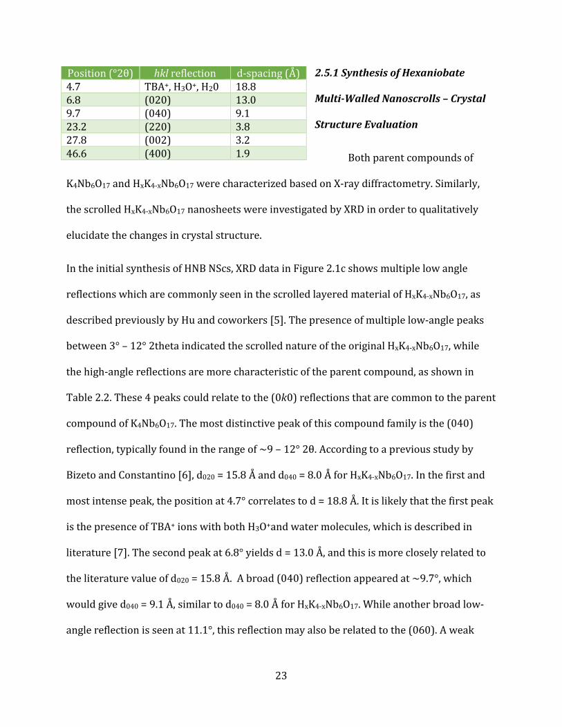
2.5.1 Synthesis of Hexaniobate
Multi-Walled Nanoscrolls – Crystal
Structure Evaluation
Both parent compounds of
K4Nb6O17 and HxK4-xNb6O17 were characterized based on X-ray diffractometry. Similarly,
the scrolled HxK4-xNb6O17 nanosheets were investigated by XRD in order to qualitatively
elucidate the changes in crystal structure.
In the initial synthesis of HNB NScs, XRD data in Figure 2.1c shows multiple low angle
reflections which are commonly seen in the scrolled layered material of HxK4-xNb6O17, as
described previously by Hu and coworkers [5]. The presence of multiple low-angle peaks
between 3° – 12° 2theta indicated the scrolled nature of the original HxK4-xNb6O17, while
the high-angle reflections are more characteristic of the parent compound, as shown in
Table 2.2. These 4 peaks could relate to the (0k0) reflections that are common to the parent
compound of K4Nb6O17. The most distinctive peak of this compound family is the (040)
reflection, typically found in the range of ~9 – 12° 2θ. According to a previous study by
Bizeto and Constantino [6], d020 = 15.8 Å and d040 = 8.0 Å for HxK4-xNb6O17. In the first and
most intense peak, the position at 4.7° correlates to d = 18.8 Å. It is likely that the first peak
is the presence of TBA+ ions with both H3O+and water molecules, which is described in
literature [7]. The second peak at 6.8° yields d = 13.0 Å, and this is more closely related to
the literature value of d020 = 15.8 Å. A broad (040) reflection appeared at ~9.7°, which
would give d040 = 9.1 Å, similar to d040 = 8.0 Å for HxK4-xNb6O17. While another broad low-
angle reflection is seen at 11.1°, this reflection may also be related to the (060). A weak
Position (°2θ) hkl reflection d-spacing (Å) 4.7 TBA+, H3O+, H20 18.8 6.8 (020) 13.0 9.7 (040) 9.1 23.2 (220) 3.8 27.8 (002) 3.2 46.6 (400) 1.9

24
(220) reflection is seen at ~23.2°, while a sharp reflection of (002) is seen at ~27.8°, and
the (400) reflection appeared at 46.6° 2theta.
Generally, the presence of multiple low-angle reflections can be a qualitative
indication that HxK4-xNb6O17 has exfoliated and possibly scrolled. Due to the large amount
of modification from the parent compound to the resulting nanoscrolls, XRD data may be
difficult to interpret. Additionally, the TBAOH and oleylamine intercalated into the scrolls
likely cause lower-angle shifts in the HxK4-xNb6O17 reflections, and may even be presenting
their own individual peaks. However, in higher angle reflections, the HNB NScs seem to
retain the characteristic reflections of the parent compound K4Nb6O17.
2.5.2 Modifying In Situ Reaction Conditions – Temperature and Time
An in situ deposition method of noble metal NPs inside preformed HNB NScs was
initially reported by our group [4]. Similarly, a procedure for synthesizing NiAu NPs was
described by She et al [3]. In combining the two previously reported methods, the synthesis
of NiAu@HNB NPPs was developed and fine-tuned to produce well defined and
monodisperse nanocomposites. An overlying goal behind the development of this method
is that essentially if any reduction method of NPs can be grown in solution, HNB NScs could
serve as a template for chain growth of said NPs to form NPPs. The realization of this goal
can lead to the combination of many different compounds, where the properties of the
nanomaterials can be tailored to suit desired requirements.
Table 2.1: Reaction Conditions – In Situ Deposition of

25
In order to complete
the goal of HNB NScs as NPP
templates in the case of NiAu
NPs, fine tuning of synthetic
procedures was necessary.
Maintaining control over the
magnetic-noble metallic NP morphology can be difficult due to the large mismatch of the
lattice parameters of Ni and Au [3]. Based on the reaction conditions listed in Table 2.1,
heat reduction to 100˚C and time increase to 60 minutes, without inert atmosphere, was
determined to be the optimal conditions. In general reduction NP syntheses, particle
formation is facilitated by inert atmospheres, especially to avoid oxidation of metal
precursors. While an inert atmosphere (Ar(g)) was used in Syntheses 1 and 2, none was
used in Syntheses 3 and 4 due to the more stable nature of both Ni and Au precursors. The
synthesis of the NiAu NPs required the preheating of Ni(acac)2 and TPPO
(triphenylphosphine oxide) in oleylamine. The necessity of the preheating can be
attributed both to the viscous nature of oleylamine at room temperature and to the
formation of small Ni nuclei which facilitates NP growth. With a lowered synthesis
temperature and increased reaction time (Synthesis 4), the NPPs produced were more
well-defined, with better filling of the HNB NScs and more monodisperse NiAu NPs, as seen
in both XRD and TEM data.
NiAu@HNB NPPs
Synthesis Temperature Time Atmosphere
1 200° C 30 min Ar(g)
2 175° C 30 min Ar(g)
3 150° C 60 min None
4 100° C 60 min None
26
2.5.3 X-Ray Diffraction Analysis – NiAu@HNB NPPs
With the adjustment in synthetic approach across Synthesis 1 – 4, XRD data (Figure
2.2a-d) supports the formation of more well-defined NPP systems. XRD analysis of
Synthesis 1 (Figure 2.2a) shows broad peaks with low intensity for Au (111) and Au
(200)/Ni (111); while Synthesis 2 (Figure 2.2b) shows a higher intensity for Au (111) and
Au (200)/Ni (111) and the appearance of a broad peak for Au (220).
In Synthesis 3 and 4 (Figure 2.2c-d), sharper peaks with higher intensities are seen
for all high angle reflections beginning at 28.1° through 80° 2theta. The sharper peaks and
higher intensities indicate a more crystalline nature of the NiAu NPs. In all 4 syntheses
(Figure 2.2a-d), characteristic low angle reflections are still seen for HNB NScs at 3° – 28°
2theta, supporting the presence of a scrolled lamellar structure.
From Synthesis 1 to Synthesis 4, the decrease in temperature and increase in time
facilitates more crystalline and monodispersed NPs and better crystallinity of the HNB
NScs.
2.5.4 Transmission Electron Microscopy Imaging – NiAu@HNB NPPs
Images obtained from TEM (Figure 2.3a-d) also supports the formation of more
well-defined NPP systems due to the modified synthetic approaches of Synthesis 1 – 4.
Synthesis 1 (Figure 2.3a) shows the formation of NiAu@HNB NPPs, with NPs located in the
inner diameter of the NScs. However NiAu NP shape ranges from oblong/square to
spherical, with large size distributions of ~ 8 – 22 nm. This could be due to the NPs forming
too quickly (30 minutes). Sheets of HNB are also seen in Synthesis 1, indicating that the

27
NScs may not have been fully preformed before the in situ deposition. The scrolls may have
even been affected by the higher temperature (200˚C) of the reaction.
Images of Synthesis 2 (Figure 2.3b) evidence poor filling of the scrolls with most
particles forming outside of the scrolls. The particles range widely in size, with diameters of
~ 6 – 25 nm; additionally, the HNB scrolls were of various sizes with some curved edges,
indicating again poor scroll morphologies, which would have affected filling. The poor
filling and wide size distribution of the NPs can also be attributed to the high temperature
(175˚C) and short time (30 minutes) of the reaction, whereby NPs formed too quickly and
unevenly.
In Synthesis 3 (Figure 2.3c), the NPPs are seen with a better filling ratio than
Synthesis 2; however, the NPs are not uniformly distributed within the scrolls. A majority
of the particles can be seen outside of the HNB NScs, agglomerating together in particular
regions. The size of the NPs ranges less drastically, from ~ 5 – 15 nm in diameter. The NScs
appear to have a better morphology in the lower temperature (150˚C) and increased time
(60 minutes) of Synthesis 3, while still showing some irregularities in shape.
Lastly, the NPPs shown from Synthesis 4 (Figure 2.3d) are more uniformly defined
and dispersed. While some free NPs are seen outside of the NScs and aggregated in some
regions, the majority of the scrolls are filled almost completely with ordered chains of NiAu
NPs. The size distribution of the NPs is much narrower than previous syntheses, ranging ~
4 – 10 nm in diameter. The NScs in general appear in better condition, with more linear
morphologies, and evenly spaced inner diameters. Overall, the synthetic parameters of
lowered temperature (100˚C) and increased time (60 minutes) produced the most
28
uniformed NiAu@HNB NPPs, as evidenced by TEM images. This supports the indications
also given by XRD that across synthetic procedures 1 – 4, more crystalline and
monodispersed NPs are formed. This in turn improves the in situ deposition of NiAu NPs
within HNB NScs, being more evenly distributed and more narrow in size range.
2.5.5 Elemental Dispersive Spectroscopy – NiAu@HNB NPPs
Used concurrently with TEM, elemental analysis was utilized to confirm the
presence of Ni, Au, and Nb in the NiAu@HNB NPPs. EDS data collected from Synthesis 1 is
shown in Figure 4; furthermore, two separate areas of the sample were analyzed, given in
Figure 4a and 4b. In the first area of Synthesis 1 (Figure 2.4a), elements which appear are:
C, O, K, Fe, Ni, Cu, Nb, and Au. The strong peak related to C is likely due to sample
preparation and some of the surfactant from the NPPs; furthermore, peaks for both Fe and
Cu are due to the grid used to view the sample. The presence of O, K, and Nb are attributed
to the HNB NScs; and lastly, a strong peak for Ni at ~1.5 keV and multiple peaks for Au at
~2 (shared with Nb), 10, and 11.5 keV are seen.
Again in the second sample area of Synthesis 1 (Figure 2.4b), the same list of
elements is shown. However this portion of the sample shows two clear peaks related to Ni
at ~1.5 and 7.5 keV, with only very low intensity Au peaks, ranging from ~9 – 13.5 keV. One
intense peak is shared by both Nb and Au (~2 keV), while other low intensity peaks of Nb
can be seen past 16 keV. Based on the quantitative data obtained from both areas of EDS
measurements shown in Figure 5, the weight percent ratio of Ni to Au is 0.04% to 0.01%.
The initial protocol has the Ni to Au precursors in a ratio of 0.5mmol to 0.15 mmol. When
considering the in situ deposition, a relative amount of Ni and Au could be lost due to the

29
formation of free NPs which would be washed off at the end of the synthesis. Considering
both areas of measurement, EDS confirms the presence of both Ni and Au, as well as Nb,
supporting the formation of NiAu@HNB NPPs, and revealing the basic ratios of Ni to Au
formed.
Conclusions
An in situ deposition procedure was developed for the well-defined nanopeapod
(NPP) formation of NiAu nanoparticles inside preformed acid-exchanged hexaniobate
nanoscrolls. Metal salt precursors of Ni(acac)2 and HAuCl4·3H2O were reduced in solution
under mild synthetic conditions in the presence of the preformed acid-exchanged
hexaniobate nanoscrolls. Reaction conditions were studied and modified in order to
produce well-defined NiAu@HNB NPP systems, with monodisperse particles evenly filling
and orienting within the nanoscrolls. The synthetic parameters studied were both time and
temperature, with the most well-defined peapod systems being those produced from lower
temperatures (100°C) and longer reaction times (60 minutes).
Overall, NiAu@HNB NPPs synthesized under the listed conditions yielded a more
narrow size distribution of NiAu nanoparticles, ranging ~ 4 – 10 nm in diameter, by evenly
filling and orienting within the inner diameter of hexaniobate nanoscrolls. The procedural
modifications were effective in terms of improving morphological control, phase purity,
and crystallinity, respectively. The relative ease of the procedure afforded even filling and
orienting of nanoparticles within the scrolls, making this method less tedious and more
easily employed in bulk synthesis. The product of NiAu@HNB NPP has many future
applications in catalytic processes, magnetic data storage, optical devices, sensors, and
templates for other assemblies.

30

31
2.7 References:
[1] Adireddy, S., Carbo, C. E., Yao, Y., Vargas, J. M., Spinu, L., & Wiley, J. B. Chem. Mater. 2013,
25, 3902−3909.
[2] Adireddy, S., Yao, Y., He, J., & Wiley, J. B. Mater. Res. Bull. 2013, 48(9), 3236-3241.
[3] She, H., Chen, Y., Chen, X., Zhang, K., Wanga, Z., & Peng, D. J. Mater. Chem. 2012, 22,
2757-2765.
[4] Adireddy, S., Carbo, C. E., Rostamzadeh, T., Vargas, J. M., Spinu, L., & Wiley, J. B., Angew.
Chem. Int. Ed. 2014, 53, 4614 –4617.
[5] Hu, C., Zhang, L., Cheng, L., Chen, J., Hou, W., Ding, W. J. Energy Chem. 2014, 23, 136–144.
[6] Bizeto, M. & Constantino, V. Mater. Res. Bull. 2004, 39, 1729–1736.
[7] Shiguihara, A., Bizeto, M., & Constantino, V. Colloids and Surfaces A: Physiochem. Eng.
Aspects. 2007, 295, 123-129.
[8] (a) Kudo, A., Tanaka, A., Domen, K., Maruya, K., Aika, K., & Onishi, T. J. Catal. 1988, 111,
67-76. (b) Zou, Z., Ye, J., Sayama, K., & Arakawa, H. Nature. 2001, 414, 625-627. (c) Zengab,
T., Chena, W., Cirtiua, C. M., Mooresa, A., Song, G., & Li, C. J. Green Chem. 2010, 12, 570-573.
[9] Lal, S., Link, S., & Halas, N. J. Nat. Photonics. 2007, 1, 641-648.
[10] Joshi, R. & Schneider, J. Chem. Soc. Rev. 2012, 41, 5285-5312.

32
Vita
Sarah Gauthier was born in New Orleans, La., and she has been a life-long resident of Slidell,
La. She obtained a Bachelor of Science in Chemistry from the University of New Orleans in
2012. In order to enrich her knowledge and understanding of the chemical sciences, she
continued at the University of New Orleans to pursue a Master’s of Science in Chemistry. As
a graduate student, she has held leadership roles in both chemical professional
organizations in the Department of Chemistry, the Graduate Chemical Society and Alpha
Chi Sigma Professional Chemistry Fraternity. During the Master’s program, she joined Dr.
John Wiley’s research group in Summer 2013 in order to pursue a thesis track degree. Her
research was focused on studying the nanocomposite structure of various hexaniobate
nanopeapods, with the addition of ferromagnetic components.
![Autonomous in-situ correction of fused deposition modeling ...gu.berkeley.edu/wp-content/uploads/2019/10/MFGLET_gu.pdftion model is trained using a ResNet 50 architecture [24]. After](https://static.fdocuments.in/doc/165x107/5f3a79787ef19f25de5ebc2e/autonomous-in-situ-correction-of-fused-deposition-modeling-gu-tion-model-is.jpg)


![Controllable in situ photo-assisted chemical deposition of CdSe …cmsoep.physics.sjtu.edu.cn › ... › XinweiWang_Nanotech_2016.pdf · 2016-03-18 · deposition (CBD) [31, 32],](https://static.fdocuments.in/doc/165x107/5f13b3f7a8f9d26dd8206299/controllable-in-situ-photo-assisted-chemical-deposition-of-cdse-a-a-xinweiwangnanotech2016pdf.jpg)