Hewlett Packard Frequency Counter
4
HEWLETT-PACKARD JOURNAL TECHNICAL INFORMATION FROM THE -ftp- LABORATORIES iLISHED BY THE HEWLETT-PACKARD COMPANY, 275 PAGE MILL ROAD, PALO ALTO, CALIFORNIA Vol. 7 No. 11 -12 ^B^^^^^^^^^^H JULY-AUGUST, 1956 A 0-1.1 MC Frequency Counter with Time Interval Markers ANEW -hp- frequency counter has been designed which incorporates a number of new features and which also includes the previously-developed features that have al ways given -hp- counters their leading posi tion in the field. The new counter measures frequencies from 0 to 1.1 megacycles and time intervals from 3 mi croseconds to 27.8 hours. These ranges suit the in strument to much of the frequency-measur ing work that goes on in a typical electronics laboratory as well as to almost any of the mechanical applications where a counter is useful such as in measuring rpm, velocity, flow rates, etc. Besides measuring frequency and time intervals, the instrument will also count events, i.e., totalize, for as long as de sired, form the ratio of two external frequen cies, measure the period or 10-period average of lower frequencies, and act as a secondary frequency standard by making available ex ternally an accurately-controlled 100 kc fre quency. The basic circuit arrangement of the new counter is shown in Fig. 3. The frequency to be measured is passed through a gate circuit which is opened by a precision time-base cir cuit for an accurately-controlled interval such as 1 second. A panel switch permits the operator to select in decade steps any of five gate times from 1 millisecond to 10 seconds. The cycles of the frequency to be measured that pass through the gate are then applied to a series of six decade counting units which indicate in illuminated numerals the num ber of cycles that have occurred while the gate was open. The measured frequency can Fig. 2. Oscillogram showing how time in terval markers (bright dots) can be used to insure measurement of pulse width on noisy signals. Fig. 1. (left.) New -hp- Model 523B Counter has been designed with such features as time interval measurement markers, circuit check lamps, and the -hp- illuminated, automatically-positioned dec imal point which prevents measurement ambig uities. (Chart on back page shows how new 523B fits into -hp- counter line.) PRINTED IN U.S.A. COPYRIGHT 1956 HEWLETT-PACKARD CO. © Copr. 1949-1998 Hewlett-Packard Co.
-
Upload
kumargpalani -
Category
Documents
-
view
42 -
download
2
description
frequency counter, hewlett packard
Transcript of Hewlett Packard Frequency Counter

HEWLETT-PACKARD
JOURNAL T E C H N I C A L I N F O R M A T I O N F R O M T H E - f t p - L A B O R A T O R I E S
i L I S H E D B Y T H E H E W L E T T - P A C K A R D C O M P A N Y , 2 7 5 P A G E M I L L R O A D , P A L O A L T O , C A L I F O R N I A
V o l . 7 N o . 1 1 - 1 2 ^B^^^^^^^^^^H
J U L Y - A U G U S T , 1 9 5 6
A 0-1.1 MC Frequency Counter with Time Interval Markers
ANEW -hp- frequency counter has been designed which incorporates a number
of new features and which also includes the previously-developed features that have al ways given -hp- counters their leading posi tion in the field. The new counter measures frequencies from 0 to 1.1 megacycles and
time intervals from 3 mi croseconds to 27.8 hours. These ranges suit the in
strument to much of the frequency-measur ing work that goes on in a typical electronics laboratory as well as to almost any of the mechanical applications where a counter is useful such as in measuring rpm, velocity, flow rates, etc. Besides measuring frequency and time intervals, the instrument will also count events, i.e., totalize, for as long as de sired, form the ratio of two external frequen
cies, measure the period or 10-period average of lower frequencies, and act as a secondary frequency standard by making available ex ternally an accurately-controlled 100 kc fre quency.
The basic circuit arrangement of the new counter is shown in Fig. 3. The frequency to be measured is passed through a gate circuit which is opened by a precision time-base cir cuit for an accurately-controlled interval such as 1 second. A panel switch permits the operator to select in decade steps any of five gate times from 1 millisecond to 10 seconds. The cycles of the frequency to be measured that pass through the gate are then applied to a series of six decade counting units which indicate in illuminated numerals the num ber of cycles that have occurred while the gate was open. The measured frequency can
Fig. 2. Oscillogram showing how time in terval markers (bright dots) can be used to insure measurement of pulse width on
noisy signals.
Fig. 1. (left.) New -hp- Model 523B Counter has been designed with such features as time interval measurement markers, circuit check lamps, and the -hp- illuminated, automatically-positioned dec imal point which prevents measurement ambig uities. (Chart on back page shows how new 523B
fits into -hp- counter line.)
P R I N T E D I N U . S . A . C O P Y R I G H T 1 9 5 6 H E W L E T T - P A C K A R D C O .
© Copr. 1949-1998 Hewlett-Packard Co.
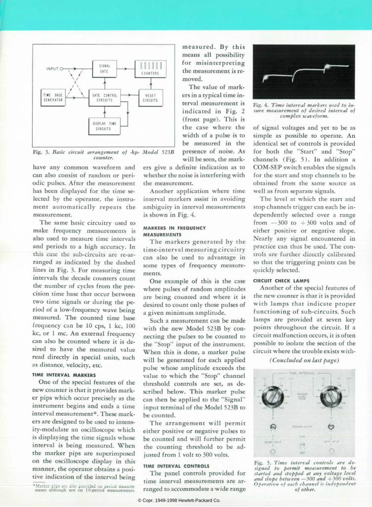
Fig. 3. Basic circuit arrangement of -hp- Model 523B counter.
m e a s u r e d . B y t h i s means all possibility for mis in terpre t ing the measurement is re moved.
The value of mark ers in a typical time in terval measurement is ind ica ted in F ig . 2 (front page). This is the case where the width of a pulse is to be measured in the presence of noise. As will be seen, the mark-
have any common waveform and can also consist of random or peri odic pulses. After the measurement has been displayed for the time se lected by the operator, the instru ment au tomat ica l ly repea ts the measurement.
The same basic circuitry used to make frequency measurements is also used to measure time intervals and periods to a high accuracy. In this case the sub-circuits are re-ar ranged as indicated by the dashed lines in Fig. 3. For measuring time intervals the decade counters count the number of cycles from the pre cision time base that occur between two time signals or during the pe riod of a low-frequency wave being measured. The counted time base frequency can be 10 cps, 1 kc, 100 kc, or 1 me. An external frequency can also be counted where it is de sired to have the measured value read directly in special units, such as distance, velocity, etc.
T I M E I N T E R V A L M A R K E R S One of the special features of the
new counter is that it provides mark er pips which occur precisely as the instrument begins and ends a time interval measurement*. These mark ers are designed to be used to intens ity-modulate an oscilloscope which is displaying the time signals whose interval is being measured. When the marker pips are superimposed on the oscilloscope display in this manner, the operator obtains a posi tive indication of the interval being * Marker pips arc also proutlcj uu ptiiud measure ments although not on 10-period measurements.
ers give a definite indication as to whether the noise is interfering with the measurement.
Another application where time interval markers assist in avoiding ambiguity in interval measurements is shown in Fig. 4.
M A R K E R S I N F R E Q U E N C Y MEASUREMENTS
The markers generated by the time-interval measuring circuitry can also be used to advantage in some types of frequency measure ments.
One example of this is the case where pulses of random amplitudes are being counted and where it is desired to count only those pulses of a given minimum amplitude.
Such a measurement can be made •with the new Model 523B by con necting the pulses to be counted to the "Stop" input of the instrument. When this is done, a marker pulse will be generated for each applied pulse whose amplitude exceeds the value to which the "Stop" channel threshold controls are set , as de scribed below. This marker pulse can then be applied to the "Signal" input terminal of the Model 523B to be counted.
The a r rangement wi l l pe rmi t either positive or negative pulses to be counted and will further permit the counting threshold to be ad justed from 1 volt to 300 volts.
T I M E I N T E R V A L C O N T R O L S The panel controls provided for
time interval measurements are ar ranged to accommodate a wide range
Fig. 4. Time interval markers used to in sure measurement of desired interval of
complex waveform.
of signal voltages and yet to be as simple as possible to operate. An identical set of controls is provided for both the "Star t" and "Stop" channels (Fig. 5) . In addi t ion a COM-SEP switch enables the signals for the start and stop channels to be obtained from the same source as well as from separate signals.
The level at which the start and stop channels trigger can each be in dependently selected over a range from —300 to +300 volts and of either positive or negative slope. Nearly any signal encountered in practice can thus be used. The con trols are further directly calibrated so that the triggering points can be quickly selected.
C I R C U I T C H E C K L A M P S Another of the special features of
the new counter is that it is provided with lamps that indicate proper functioning of sub-circuits. Such lamps are provided at seven key points throughout the circuit. If a circuit malfunction occurs, it is often possible to isolate the section of the circuit where the trouble exists with-
(Concluded on last page)
T I M E I N T E R V A L
T R I Q O E R L E V E L «H.T»
Fig. 5. Time interval controls are de signed to permit measurement to be started and stopped at any voltage level and slope between —300 and +300 volts. Operation oj each channel if independent
of other.
© Copr. 1949-1998 Hewlett-Packard Co.
The -/if- Readout System
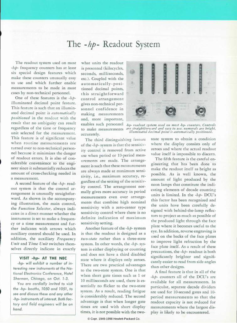
The readout system used on most -hp- frequency counters has at least six special design features which make these counters unusually easy to use and which further enable measurements to be made in most cases by non-technical personnel.
One of these features is the -hp-
illuminated decimal point feature. This feature is such that an illumin ated decimal point is automatically
positioned in the readout with the result that no ambiguity can result regardless of the time or frequency unit selected for the measurement. This feature is of significant value when routine measurements are turned over to non-technical person nel because it minimizes the danger of readout errors. It is also of con siderable convenience to the engi neer since it substantially reduces the amount of cross-checking needed in a measurement.
A second feature of the -hp- read out system is that the control ar rangement is unusually straightfor ward. As shown in the accompany ing illustration, the main control, the Function Selector, always indi cates in a direct manner whether the instrument is set to make a frequen cy or a time measurement and fur ther indicates with arrows which auxiliary control should be used. In addition, the auxiliary Frequency
Unit and Time Unit switches them selves directly indicate in exactly
V I S I T - h p - A T T H E N E C - h p - w i l l e x h i b i t a n u m b e r o f i n
terest ing new instruments at the Na t ional Electronics Conference, Hotel Sherman, Ch icago , on Oc t . 1 -3 .
You a re co rd ia l l y i nv i ted to v i s i t the -hp- booths, 1050 and 1051, to see and discuss these and any other -hp- instruments of interest. Both fac to ry and f ie ld eng ineers w i l l be on hand.
what units the readout is presented (kilocycles, seconds, milliseconds, etc.). Coupled with the a u t o m a t i c a l l y - p o s i tioned decimal points, th i s s t ra igh t forward cont ro l a r rangement gives non-technical per sonnel confidence in making measurements and, more important, enables such personnel to make measurements accurately.
The third distinguishing feature of the -hp- system is that the sensitiv ity control is removed from active use when period or 10-period meas urements are made. The arrange ment is such that these measurements are always made at maximum sensi tivity, i.e., maximum accuracy, re gardless of the setting of the sensitiv ity control. The arrangement nor mally gives more accuracy in period measurements even over arrange ments that combine high nominal sensitivity with a zero-center type sensitivity control where there is no defini te indication of maximum sensitivity setting.
Another feature of the -hp- system is that the readout is designed as a two-state rather than a three-state system. In other words, the -hp- sys tem is either displaying or counting and does not have a third disabled state where it displays only zeroes. There are two practical advantages to the two-state system. One is that when short gate times such as 1 or 10 milliseconds are used, there is es sentially no flicker to the two-state system. As a result, reading fatigue is considerably reduced. The second advantage is that when longer gate times are used with short display times, it is not possible with the two-
•hp- readout system used on most -hp- counters. Controls are straightforn-ard and easy to use, numerals are bright,
illuminated decimal point is automatically positioned.
state system to obtain a condition where the display consists only of zeroes and where the actual readout value itself is impossible to discern.
The fifth feature is the careful en gineering that has been done to make the readout itself as bright as possible . As is wel l known, the amount of light produced by the neon lamps that constitute the indi cating elements of decade counting units is limited. In the -hp- DCU's this factor has been recognized and the units have been carefully de signed with behind-the-lamp reflec tors to project as much as possible of the produced light through the face plate where it becomes useful to the eye. In addition, reverse engraving is used on the backs of the face plates to improve light refraction by the face plate itself. As a result of these precautions, the -hp- readout is both significantly brighter and signifi cantly easier to read from side angles than other designs.
A final feature is that in all of the -hp- counters all of the DCU's are available for all measurements. In particular, separate decade dividers are used for 10-second gates and 10- period measurements so that the readout capacity is not reduced for measurements where the largest dis play is likely to be encountered.
© Copr. 1949-1998 Hewlett-Packard Co.
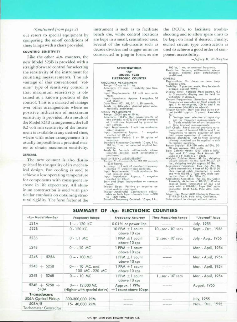
(Continued from page 2)
out resort to special equipment by comparing the on-off conditions of these lamps with a chart provided.
C O U N T I N G S E N S I T I V I T Y
Like the other -hp- counters, the new Model 523B is provided with a straightforward control for selecting the sensitivity of the instrument for count ing measurements . The ad vantage of this conventional "vol ume" type of sensitivity control is tha t maximum sens i t iv i ty i s ob tained at a known position of the control. This is a marked advantage over other arrangements where no posi t ive indicat ion of maximum sensitivity is provided. As a result of the Model 523B arrangement, the full 0.2 volt rms sensitivity of the instru ment is available at any desired time, where with other arrangements it is usually impossible as a practical mat ter to obtain maximum sensitivity.
GENERAL
The new counter is also distin guished by the quality of its mechan ical design. Fan cooling is used to achieve a low operating temperature for components with consequent in crease in life expectancy. All alum inum construction is used with par ticular emphasis on obtaining struc tural rigidity. The form factor of the
instrument is such as to facilitate bench use, while control locations are kept in a small, centralized area. Several of the sub-circuits such as decade dividers and trigger units are constructed in plug-in form, as are
the DCU's , to faci l i ta te t rouble shooting and to allow spare units to be kept on hand if desired. Finally, etched circuit type construction is used to achieve a good order of com ponent accessibility.
—Jeffery B. Wolfington
SPECIF ICATIONS -hp-
M O D E L 5 2 3 B E L E C T R O N I C C O U N T E R
F R E Q U E N C Y M E A S U R E M E N T R a n g e : 1 0 c p s t o 1 . 1 m e . A c c u r a c y : + 1 c o u n t  ± s t a b i l i t y ( s e e G e n
e r a l ) . I n p u t R e q u i r e m e n t s : 0 . 2 v o l t r m s m à n i
m u m . I n p u t I m p e d a n c e : A p p r o x . 1 m e g o h m , 3 0
H f i f s h u n t . G a t e T i m e : . G O T , . 0 1 , 0 . 1 , 1 , 1 0 s e c o n d s . R e a d s I n : K i l o c y c l e s ; d e c i m a l p o i n t a u t o
m a t i c a l l y p o s i t i o n e d . P E R I O D M E A S U R E M E N T
R a n g e : . 0 0 0 0 1 c p s t o 1 0 k c . A c c u r a c y : Â ± 0 . 3 % ( f o r m e a s u r e m e n t s o f
o n e p e r i o d ) ; Â ± . 0 3 % ( 1 0 p e r i o d a v e r a g e ) a t 1 v o l t r m s . I m p r o v e d b y g r e a t e r i n p u t v o l t a g e .
I n p u t R e q u i r e m e n t s : 1 v o l t r m s m i n i m u m ; d i r e c t c o u p l e d .
I n p u t I m p e d a n c e : A p p r o x . 1 m e g o h m s h u n t e d b y 4 0 Â ¿ / / i f .
M e a s u r e m e n t P e r i o d : 1 o r 1 0 c y c l e s o f u n k n o w n .
S t a n d a r d F r e q u e n c y C o u n t e d : 1 0 c p s , 1 k c , 1 0 0 k c , 1 m e , o r e x t e r n a l a p p l i e d f r e q u e n c y .
R e a d s I n : S e c o n d s , m i l l i s e c o n d s , m i c r o s e c o n d s ; d e c i m a l p o i n t a u t o m a t i c a l l y p o s i t i o n e d .
T I M E I N T E R V A L M E A S U R E M E N T R a * " i c ' " * T : c r 2 c " " % T J * ' * " 1 n O ' " " " ^ c e c c n d s
( 2 7 . S h o u r s ) . " A c c u r a c y : Â ± 1 u n i t o f s t a n d a r d f r e q u e n c y
c o u n t e d  ± s t a b i l i t y ( s e e G e n e r a l ) . I n p u t R e q u i r e m e n t s : 1 v o l t m i n i m u m . D i
r e c t c o u p l e d i n p u t . I n p u t I m p e d a n c e : A p p r o x . 1 m e g o h m
s h u n t e d b y 2 5 / Â ¿ Â ¿ Ã f . S t a r t a n d S t o p : I n d e p e n d e n t o r c o m m o n
i n p u t . T r i g g e r S l o p e : P o s i t i v e o r n e g a t i v e o n
s t a r t a n d o r s t o p i n p u t . T r i g g e r A m p l i t u d e : C o n t i n u o u s l y a d j u s t
a b l e o n b o t h i n p u t c h a n n e l s f r o m â € ” 3 0 0 t o + 3 0 0 v o l t s .
S t a n d a r d F r e q u e n c y C o u n t e d : 1 0 c p s , 1 k c ,
1 0 0 k c , 1 m e ; o r e x t e r n a l f r e q u e n c y . R e a d s i n : S e c o n d s , m i l l i s e c o n d s , m i c r o
s e c o n d s ; d e c i m a l p o i n t a u t o m a t i c a l l y p o s i t i o n e d .
G E N E R A L R e g i s t r a t i o n : S i x p l a c e s o n n e o n l a m p
d e c a d e u n i t s . S t a b i l i t y : 2 p p m p e r w e e k . M a y b e s t a n d
a r d i z e d a g a i n s t W W V . D i s p l a y T i m e : V a r i a b l e f r o m a p p r o x . 0 . 1
t o 5 s e c o n d s ; d i s p l a y c a n b e h e l d i n d e f i n i t e l y i f d e s i r e d .
O u t p u t F r e q u e n c i e s : S e c o n d a r y s t a n d a r d f r e q u e n c i e s a v a i l a b l e a t f r o n t p a n e l : 1 0 c p s , 1 k c r e c t a n g u l a r , 1 0 0 k c a n d 1 m e s i n e - w a v e ( s t a b i l i t y a s a b o v e ) .
T r i g g e r O u t p u t : S t a r t a n d S t o p p u l s e o u t p u t ( w i d t h a p p r o x . 5 / Â ¿ s e e s ) . A v a i l a b l e f o r : 1 . V o l t a g e l e v e l s e l e c t i o n o f i n p u t s i g
n a l f o r f r e q u e n c y m e a s u r e m e n t s . 2 . Z - a x i s m o d u l a t i o n o f o s c i l l o s c o p e f o r
t i m e i n t e r v a l m e a s u r e m e n t s . S e l f C h e c k : P a n e l c o n t r o l p r o v i d e s a u t o
m a t i c c o u n t o f i n t e r n a l 1 0 0 k c a n d 1 m e f r e q u e n c i e s t o a s s u r e a c c u r a c y o f g a t e a n d p r o p e r o p e r a t i o n o f c o u n t e r s .
E x t e r n a l S t a n d a r d : 1 0 0 k c f r o m e x t e r n a l p r i m a r y s t a n d a r d c a n b e a p p l i e d t o u n i t f o r h i g h e s t a c c u r a c y .
P o w e r S u p p l y : 1 1 5 / 2 3 0 v o l t s  ± 1 0 % , 5 0 - 6 0 c p s , a p p r o x . 2 8 5 w a t t s .
S i z e : C a b i n e t M o u n t : 1 3 3 A " w i d e x 1 6 1 4 " h i g h a n d 2 1 " d e e p . R a c k M o u n t : 1 9 " w i d e x 1 4 " h i g h x 2 1 " d e e p .
W e i g h t : C a b i n e t M o u n t : 4 8 I D S . , s h i p p i n g w e i n h t n n p r n v R S I h * P n r l r M m i n t - 4 9 I b s . , s h i p p i n g w e i g h t a p p r o x 8 0 ! b s .
A c c e s s o r i e s F u r n i s h e d : T w o - h p - A C - 1 6 K C a b l e A s s e m b l i e s , 4 f e e t o f R G - 5 8 U 5 0 o h m c o a x i a l c a b l e t e r m i n a t e d a t e a c h e n d w i t h U G - 8 8 / U T y p e B N C m a l e c o n n e c t o r s . C a n o f A i r F i l t e r O i l .
A c c e s s o r i e s A v a i l a b l e : - h p - A C - 1 6 D C a b l e A s s e m b l y , 4 4 i n c h e s o f R G - 5 8 / U 5 0 o h m c o a x i a l c a b l e t e r m i n a t e d a t o n e e n d o n l y w i t h a U G - 8 8 / U T y p e B N C m a l e c o n n e c t o r . $ 2 . 6 5 f . o . b . P a l o A l t o , C a l i f o r n i a .
P r i c e : - h p - M o d e l 5 2 3 B E l e c t r o n i c C o u n t e r , S 1 1 7 5 . 0 0 f . o . b . P a l o A l t o , C a l i f o r n i a .
D a t a s u b j e c t t o c h a n g e w i t h o u t n o t i c e .
S U M M A R Y O F - h p - E L E C T R O N I C C O U N T E R S - h p - M o d e l N u m b e r F r e q u e n c y R a n g e F r e q u e n c y A c c u r a c y Time Measuring Range " J o u r n a l " I s s u e
521A 1 — -120 KC 0.01 % or power l ine Ju ly , 1955 522B O - 1 2 0 K C 10 PPM ±1 count
above 10 cps 10/j.sec- 10 sees Sept . -Oct . , 1953
523B 0 - 1 . 1 M C 1 PPM :±1 count above 10 cps
3 /¿sec - 1 0 sees Ju ly -Aug . , 1956
524B 0 â € ” - 1 0 M C 1 PPM HT! count above 10 cps
Mar . -Ap r i l , 1954
524B — 525A 0 â € ” - 1 0 0 M C 1 PPM ±1 count above 10 cps
Mar . -Ap r i l , 1954
5 2 4 B - 5 2 5 B 0 â € ” - 1 0 M C , a n d 1 0 0 M C - 2 2 0 M C
1 PPM ±1 count above 10 cps
Mar . -Ap r i l , 1954
5 2 4 B + 5 2 6 B 0— - 10 MC 1 PPM :±1 count above 10 cps
1 //sec - 10' sees Mar . -Ap r i l , 1954
5 2 4 B + 5 2 5 B 540A
0—-1 2,000 MC (Higher with special det 'rs)
Approx. 1 PPM ±1 count above 10 cps
August, 1955
T r a n s d u c e r s 506A Opt ica l P ickup 300-300,000 RPM July, 1955
5 0 8 A / B Tachometer Generator
15- 40,000 RPM Nov. -Dec. , 1953
© Copr. 1949-1998 Hewlett-Packard Co.