Here, we supplement the order information with such as...
113
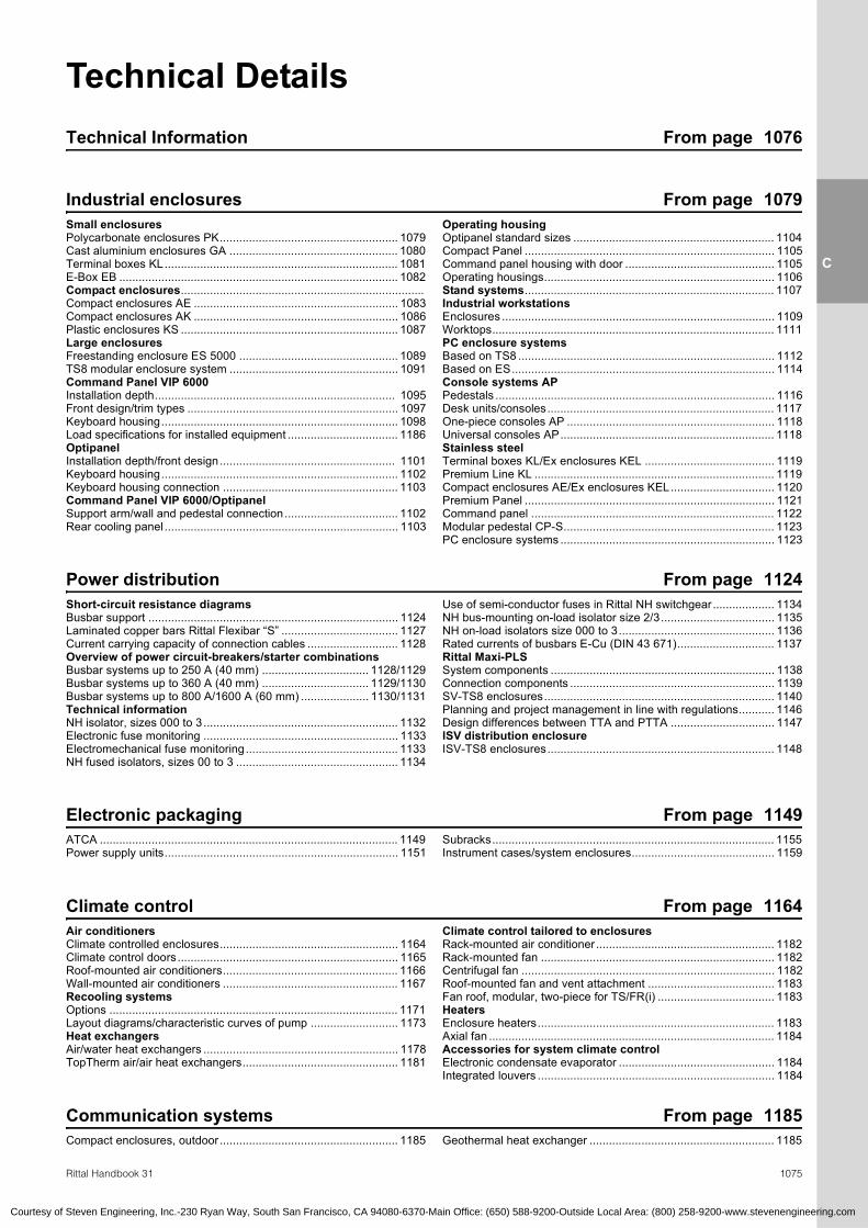
1074 To ensure a perfect solution, the final element that is needed is technical background information. Here, we supplement the order information with detailed drawings, load curves, parts lists and performance diagrams. Additional information and download options such as approvals, CAD drawings or assembly instructions are available online at www.rittal-corp.com. R Courtesy of Steven Engineering, Inc.-230 Ryan Way, South San Francisco, CA 94080-6370-Main Office: (650) 588-9200-Outside Local Area: (800) 258-9200-www.stevenengineering.com
Transcript of Here, we supplement the order information with such as...

1074
To ensure a perfect solution, the final element that is needed is technical
background information. Here, we supplement the order information with
detailed drawings, load curves, parts lists and performance diagrams.
Additional information and download options such as approvals,
CAD drawings or assembly instructions are available online at
www.rittal-corp.com.
R
Courtesy of Steven Engineering, Inc.-230 Ryan Way, South San Francisco, CA 94080-6370-Main Office: (650) 588-9200-Outside Local Area: (800) 258-9200-www.stevenengineering.com
1075Rittal Handbook 31
C
Technical DetailsTechnical Information From page 1076
Industrial enclosures From page 1079Small enclosuresPolycarbonate enclosures PK....................................................... 1079Cast aluminium enclosures GA .................................................... 1080Terminal boxes KL........................................................................ 1081E-Box EB ...................................................................................... 1082Compact enclosures...........................................................................Compact enclosures AE ............................................................... 1083Compact enclosures AK ............................................................... 1086Plastic enclosures KS ................................................................... 1087Large enclosuresFreestanding enclosure ES 5000 ................................................. 1089TS8 modular enclosure system .................................................... 1091Command Panel VIP 6000Installation depth.......................................................................... 1095Front design/trim types ................................................................. 1097Keyboard housing......................................................................... 1098Load specifications for installed equipment .................................. 1186OptipanelInstallation depth/front design...................................................... 1101Keyboard housing......................................................................... 1102Keyboard housing connection ...................................................... 1103Command Panel VIP 6000/OptipanelSupport arm/wall and pedestal connection................................... 1102Rear cooling panel ........................................................................ 1103
Operating housingOptipanel standard sizes .............................................................. 1104Compact Panel ............................................................................. 1105Command panel housing with door .............................................. 1105Operating housings....................................................................... 1106Stand systems............................................................................. 1107Industrial workstationsEnclosures .................................................................................... 1109Worktops....................................................................................... 1111PC enclosure systemsBased on TS8 ............................................................................... 1112Based on ES................................................................................. 1114Console systems APPedestals ...................................................................................... 1116Desk units/consoles...................................................................... 1117One-piece consoles AP ................................................................ 1118Universal consoles AP.................................................................. 1118Stainless steelTerminal boxes KL/Ex enclosures KEL ........................................ 1119Premium Line KL .......................................................................... 1119Compact enclosures AE/Ex enclosures KEL................................ 1120Premium Panel ............................................................................. 1121Command panel ........................................................................... 1122Modular pedestal CP-S................................................................. 1123PC enclosure systems .................................................................. 1123
Power distribution From page 1124Short-circuit resistance diagramsBusbar support ............................................................................. 1124Laminated copper bars Rittal Flexibar “S” .................................... 1127Current carrying capacity of connection cables ............................ 1128Overview of power circuit-breakers/starter combinationsBusbar systems up to 250 A (40 mm) ................................. 1128/1129Busbar systems up to 360 A (40 mm) ................................. 1129/1130Busbar systems up to 800 A/1600 A (60 mm) ..................... 1130/1131Technical informationNH isolator, sizes 000 to 3 ............................................................ 1132Electronic fuse monitoring ............................................................ 1133Electromechanical fuse monitoring............................................... 1133NH fused isolators, sizes 00 to 3 .................................................. 1134
Use of semi-conductor fuses in Rittal NH switchgear................... 1134NH bus-mounting on-load isolator size 2/3................................... 1135NH on-load isolators size 000 to 3................................................ 1136Rated currents of busbars E-Cu (DIN 43 671).............................. 1137Rittal Maxi-PLSSystem components ..................................................................... 1138Connection components ............................................................... 1139SV-TS8 enclosures....................................................................... 1140Planning and project management in line with regulations........... 1146Design differences between TTA and PTTA ................................ 1147ISV distribution enclosureISV-TS8 enclosures...................................................................... 1148
Electronic packaging From page 1149ATCA ............................................................................................ 1149Power supply units........................................................................ 1151
Subracks....................................................................................... 1155Instrument cases/system enclosures............................................ 1159
From page 1164Air conditionersClimate controlled enclosures....................................................... 1164Climate control doors.................................................................... 1165Roof-mounted air conditioners...................................................... 1166Wall-mounted air conditioners ...................................................... 1167Recooling systemsOptions ......................................................................................... 1171Layout diagrams/characteristic curves of pump ........................... 1173Heat exchangersAir/water heat exchangers ............................................................ 1178TopTherm air/air heat exchangers................................................ 1181
Climate control tailored to enclosuresRack-mounted air conditioner ....................................................... 1182Rack-mounted fan ........................................................................ 1182Centrifugal fan .............................................................................. 1182Roof-mounted fan and vent attachment ....................................... 1183Fan roof, modular, two-piece for TS/FR(i) .................................... 1183HeatersEnclosure heaters......................................................................... 1183Axial fan ........................................................................................ 1184Accessories for system climate controlElectronic condensate evaporator ................................................ 1184Integrated louvers ......................................................................... 1184
Communication systems From page 1185Compact enclosures, outdoor....................................................... 1185 Geothermal heat exchanger ......................................................... 1185
Climate control
Courtesy of Steven Engineering, Inc.-230 Ryan Way, South San Francisco, CA 94080-6370-Main Office: (650) 588-9200-Outside Local Area: (800) 258-9200-www.stevenengineering.com

Technical Information
1076 Rittal Handbook 31
Tech
nica
l Inf
orm
atio
n
C
Surface protectionThe triple treatment of outer surfaces – phosphating, electrophoretic dipcoat-priming and textured powder-coating – provides optimum corrosion protection for enclosures such as TS, AE and KL. To ensure optimum corrosion protection in extreme climates, aluminium or zinc-plated metal with subsequent zinc phosphating and powder-coating are used for outdoor enclosures.
The standard coating is resistant to: ● Mineral oils● Lubricants● Machining emulsions● Solvent (briefly as for
cleaning)● Weak acids and alkalines
This has been tested and confirmed by various independent test institutes.
Quality is ensured by continuous process monitoring.
Priming or powder coating suitable for over-paintingAfter careful cleaning of the surface, the standard coating may be over-painted with: ● DD gloss paints● Single and dual-component
gloss paints● Car repair paints● Powder paints● Water-based paintsIf in doubt, perform a compatibility test. Always follow the paint manufacturer’s instructions. When over-painting, take care not to exceed 180°C (356°F) and a baking time of 15 minutes.
Special coatingsTropical coating: For high corrosion resistance in warm, damp climates, also suitable for outdoor and long-term use.
Chemical paint: For the best possible resistance to organic and inorganic substances that can be achieved with paint.
Outdoor use of enclosuresIn order to guarantee satisfactory long-term function of enclosures in outdoor environments, relevant environmental factors need to be taken into account.
These include: ● UV radiation, the corrosive
action of air pollution, rain, ice, snow, wind and other factors in special climate conditions.
Influence of weather conditions on the outer coatingIt is necessary to ensure the UV and corrosion resistance of components exposed to the weather. A special 3-phase paint finish is suitable for outdoor installations. For outdoor installation of an enclosure, a rain canopy should be provided to protect the seal against permanent humidity and exposure to prolonged UV radiation.
Condensation inside the enclosureCondensation needs to be prevented with special measures, for example by venting or heating the enclosure.
Protection categoryThe enclosure is exposed to extreme weather conditions during outdoor use. Long periods of rain, snow, ice, high winds and temperature fluctuations place high demands on the enclosure’s sealing gaskets. Often, the protection category for outdoor weather exposure described in DIN VDE 0100, part 737, point 5.2, IP X3 is insufficient to provide permanent protection for electrical installations.
Standard IEC 60 529 offers the option of labeling with the supplementary letter “W”. Enclosures labeled this way are suitable for use in weather conditions agreed between the manufacturer and the user, and are equipped with additional protective features or techniques (rain canopy, special paints, special color shades).
The three-phase coating process for enclosuresCoating procedures Technical properties Technical specifications
Degreasing,iron phosphating,rinsing
Neutralizes electric resistance, provides temporary corrosion protection and better adhesion of paint.
Anodicdipcoat priming
Uniform coating on all surfaces, edges and recesses provides superior corrosion protec-tion.
Coat thickness Approximately 20 µm
Erichsen cupping DIN EN ISO 20 482 ≥ 4 mm (0.2″)
Buchholz hardness DIN EN ISO 2815 ≥ 80
Cross cutting DIN EN ISO 2409 Gt 0
The primer is readily over-painted and free from heavy metals, chromate and silicone.
Stove enameling
Texturedpowder coating
The special merits of powder-painting are high durability, good corrosion protection, good resistance to chemicals, temperature, and outdoor environment, and can be easily cleaned.
Outer coating thickness 60 µm . . . 110 µm
Erichsen cupping DIN EN ISO 20 482 ≥ 4 mm (0.2″)
Buchholz hardness DIN EN ISO 2815 ≥ 80
Cross cutting DIN EN ISO 2409 Gt 0
The powder coating is readily over-painted and is free from heavy metals, chromate and silicone.
Stove enameling Overall outer coating thickness Ø 80 µm . . . 135 µm
Technical Information
Courtesy of Steven Engineering, Inc.-230 Ryan Way, South San Francisco, CA 94080-6370-Main Office: (650) 588-9200-Outside Local Area: (800) 258-9200-www.stevenengineering.com

Tech
nica
l Inf
orm
atio
n
Technical Information
1077Rittal Handbook 31
C
Protection categories to IEC 60 529The IP protection category is characterized by 2 numbers. Example of protection category: IP 43: Code letters
First characteristic numeral Second characteristic numeral
Degrees of protection for protection against contact and foreign bodies:First characteristic numeral
Degrees of protection for protection against water:Second characteristic numeral
Firstcharacteristic numeral
Degree of protection Secondcharacteristic numeral
Degree of protection
Description Definition Description Definition
Protected against solid for-eign objects with a diameter of 50 mm (2.0″) and greater
The object probe, a sphere 50 mm (2.0″) in diameter, must not penetrate fully1).
Protected against vertically falling water drops
Vertically falling drops shall have no harmful effects.
Protected against solid for-eign objects with a diameter of 12.5 mm (0.5″) and greater
The object probe, a sphere 12.5 mm (0.5″) in diameter, must not penetrate fully1). The articulated test finger may penetrate up to its length of 80 mm (3.1″), but adequate distance must be adhered to.
Protected against vertically falling water drops when the enclosure is tilted up to 15°
Vertically falling drops must not have any harmful effects when the enclosure is tilted up to 15° in both directions from the vertical.
Protected against solid for-eign objects with a diameter of 2.5 mm (0.1″) and greater
The object probe, a sphere 2.5 mm (0.1″) in diameter, must not penetrate at all1).
Protected against spraying water
Water sprayed at an angle of up to 60° on either side of the vertical must have no harmful effects.
Protected against solid for-eign objects with a diameter of 1.0 mm (0.04″) and greater
The object probe, a sphere 1.0 mm (0.04″) in diameter, must not penetrate at all1).
Protected against splashing water
Water splashed on the enclo-sure from every direction must not have any adverse effects.
Dust-protected The ingress of dust is not fully prevented, but dust may not enter to such an extent as to impair satisfactory operation of the device or safety.
Protected against water jets Water splashed on the enclo-sure from every direction must not have any adverse effects.
Dust-tight No ingress of dust at a partial vacuum of 20 mbar inside the enclosure.
Protected against powerful water jets
Water splashed on the enclo-sure from every direction in a powerful jet must not have any adverse effects.
Protected against the effects of temporary immersion in water
Water must not ingress to such an extent as to cause harmful effects when the enclosure is temporarily immersed in water under standardized pressure and time conditions.
Water with high-pressure/steam-jet cleaning2)
Water directed at the enclo-sure from every direction under greatly increased pres-sure must not have any adverse effects.
1) The full diameter of the object probe must not pass through an opening of the enclosure. 2) This test is not regulated by EN 60 529, but by DIN EN 40 050, part 9.
Extracts from BS EN 60 259: 1991 are reproduced with the permission of BSI. Complete editions of the standards can be obtained by post from BSI Customer Services, 889 Chiswick High Road, London W4 4AL
IP
4 3
1 1
2 2
3 3
4 4
5 5
6 6
7
9K
Courtesy of Steven Engineering, Inc.-230 Ryan Way, South San Francisco, CA 94080-6370-Main Office: (650) 588-9200-Outside Local Area: (800) 258-9200-www.stevenengineering.com

Technical Information
1078 Rittal Handbook 31
Tech
nica
l Inf
orm
atio
n
C
NEMAThe National Electrical Manufacturers Association (NEMA) is a standards organization in Washington, USA, which publishes a number of technical standards but does not test or certify products itself.
The following NEMA classification outlines the protection of individuals from unintentional contact with equipment and the protection of an enclosure from external factors.
Further information on protection categories may be foundon the Internet at: www.rittal-corp.com
Technical information
UL/NEMA Type Intended use and description
1 Enclosures for use predominantly inside. Protection against the penetration of foreign bodies.
3 Enclosures for use predominantly inside. Protection against the penetration of solid bodies, protection against the ingress of rain and dust and damage caused by icing.
3R Enclosures for use predominantly inside. Protection against the penetration of solid bodies, protection against the ingress of rain and dust and damage caused by icing.
3S Enclosures for use predominantly inside. Protection against rain, snow and foreign bodies. External mechanisms remain usable despite being coated in ice.
4 Enclosures for indoor or outdoor use. Protection against rain, foreign bodies, splashed water and hosed water and against damage caused by icing on the exterior of the enclosure.
4x Enclosures for indoor or outdoor use. Protection against rain, foreign bodies, splashed water and hosed water and against damage caused by icing on the exterior of the enclosure.
12, 12K Enclosures for use predominantly inside. Protection against dust deposits, foreign bodies and non-corrosive dripping liquids.
13 Enclosures for use predominantly inside. Protection against dust deposits, sprayed water, oil, and non-corrosive coolants.
The UL classifications are not directly comparable with IP protection categories, since both the test conditions and the evaluation of the test results are different.
Certifications and permitsProduct certifications and approvals are key requirements for the global acceptance of industrial products.
Rittal products meet the highest internationally recognized quality standards. All components are subjected to the most stringent testing in accordance with international standards and regulations.
The consistently high product quality is ensured by a comprehensive quality management system. Regular production inspections by external test institutes also guarantee compliance with global standards.
A precise allocation of products to marks of conformity can be found on our product and service pages on the Internet: www.rittal-corp.com
Enclosure designs guaranteeing hygiene and effective cleaningSpecial applications require special solutions – in terms of materials, design and security.
This is also true for applications in the food and hygiene sector and in sensitive fields such as medical technology and pharmaceuticals.
Consequently, Rittal has been looking at the quality standards in those branches and has subjected its products to stringent testing.
The CE symbolAll Rittal products subject to an EU Directive which envisages labeling are labeled CE.
Up-to-date manufacturer declarations for the respective products are available on the Internet at: www.rittal-corp.com
Note:The CE symbol is not a quality symbol. Conformity is certified by the manufacturer on an independent basis.
This distinguishes CE labeling from approvals, which are issued by independent bodies.
Grounding The grounding must be designed by the manufacturer of switchgear in accordance with the relevant VDE provisions or local regulations.
The enclosure packs generally contain grounding materials (screws, nuts, washers). The assembly instructions contain recommendations on installing a protective ground.
The pre-assembled ground straps available in various cross-sections and lengths, are intended to make assembly of a ground conductor easier.
Further information can be found in our technical documentation “PE ground conductor connection, current carrying capacity”.
Courtesy of Steven Engineering, Inc.-230 Ryan Way, South San Francisco, CA 94080-6370-Main Office: (650) 588-9200-Outside Local Area: (800) 258-9200-www.stevenengineering.com

Small enclosures
Industrial Enclosures
1079Rittal Handbook 31/Enclosure Systems
C
1.
Indu
stria
l Enc
losu
res
1.1 Polycarbonate enclosures PKWith cable gland Page 100
H4
H2
38
H120
16.2
H5
H3
20.8
28.4
45 28
1
24.5
24.5
35.5
25.5
12.5
6
B2
B1
H4
B4
H3
B3
H2
H1
H5
B5
B2
B1
B4H
4
H5
B5
B3
H2
H1
H3
B3
H3
B5
H5
B4
H4
B2
H1
B1
H2
1
2
2
1
1.1 Polycarbonate enclosures PKPages 100 – 101
B1 =B2 =B3 =
B4 =
B5 =
Enclosure widthUsable widthCenter/center wall attachment outside the sealCenter/center wall attachment in the enclosureClearance width
H1 =H2 =H3 =
H4 =
H5 =
Enclosure heightUsable heightCenter/center wall attachment outside the sealCenter/center wall attachment in the enclosureClearance height
T1 =T2 =T3 =T4 =
Overall depthUsable enclosure depthEnclosure depthClearance height available for installation
Part No. PKVersion
Height dimensions mm Width dimensions mm Depth dimensions mm
Solidlids
Transparent lids H1 H2 H3 H4 H5 B1 B2 B3 B4 B5 T1 T2 T3 T4
9500.000 – A 65 59 50 25 36 65 59 50 – 36 57 33 41 45
9501.000 – A 65 59 50 25 36 65 59 50 – 36 81 33 41 69
9502.000 – A 65 59 50 – 36 94 88 79 50 64 57 33 41 45
9503.000 – A 65 59 50 – 36 94 88 79 50 64 81 33 41 69
9504.000 9504.100 A 94 88 79 50 64 94 88 79 50 64 57 33 41 45
9505.000 – A 94 88 79 50 64 94 88 79 50 64 81 33 41 69
9506.000 9506.100 A 110 104 95 65 80 110 104 95 65 80 66 42 50 53
9507.000 9507.100 A 110 104 95 65 80 110 104 95 65 80 90 42 50 77
9508.000 9508.100 A 94 88 79 50 64 130 124 115 90 101 57 33 41 45
9509.000 9509.100 A 94 88 79 50 64 130 124 115 90 101 81 33 41 69
9510.000 9510.100 A 130 124 115 70 101 130 124 115 70 101 75 51 59 63
9511.000 9511.100 A 130 124 115 70 101 130 124 115 70 101 99 51 59 87
9512.000 9512.100 A 94 88 79 50 64 180 174 165 120 150 57 33 41 45
9513.000 9513.100 A 94 88 79 50 64 180 174 165 120 150 81 33 41 69
9514.000 9514.100 B 110 103 95 50 80 180 173 165 120 128 90 63 71 75
9515.000 9515.100 B 110 103 95 50 80 180 173 165 120 128 111 63 71 97
9516.0001) 9516.100 B 110 103 95 50 80 180 173 165 120 128 165 63 71 150
9517.000 9517.100 C 180 173 165 120 128 182 175 167 120 152 90 63 71 75
9518.000 9518.100 C 180 173 165 120 128 182 175 167 120 152 111 63 71 97
9519.0001) 9519.100 C 180 173 165 120 128 182 175 167 120 152 165 63 71 150
9520.000 9520.100 C 180 173 165 120 128 254 247 239 190 224 90 63 71 75
9521.000 9521.100 C 180 173 165 120 128 254 247 239 190 224 111 63 71 97
9522.0001) 9522.100 C 180 173 165 120 128 254 247 239 190 224 165 63 71 150
9523.000 9523.100 B 254 248 239 190 224 360 355 346 240 309 111 63 71 97
9524.0001) 9524.100 B 254 248 239 190 224 360 355 346 240 309 165 63 71 1501) With slanted lid
T2
T3
T4
T1
Ø 5
.5Ø
14
Does not apply to PK 9500.000, PK 9501.000
Does not apply to PK 9502.000, PK 9503.000
1
2
Version BVersion A Version C
Note: 25.4 mm = 1 inch1 mm = 0.03937008″
Courtesy of Steven Engineering, Inc.-230 Ryan Way, South San Francisco, CA 94080-6370-Main Office: (650) 588-9200-Outside Local Area: (800) 258-9200-www.stevenengineering.com
Part No. PKwith cable gland H1 H2 H3 H4 H5
9530.000 52 47 40 39.4 30.4
9531.000 65 60 53 52.4 43.4
Note: 25.4 mm = 1 inch1 mm = 0.03937008″
Does not apply to PK 9531.000
Does not apply to PK 9530.000
1
2

Industrial EnclosuresSmall enclosures
1080 Rittal Handbook 31/Enclosure Systems
C
1.
Indu
stria
l Enc
losu
res
Ø D1
T4
Ø D2
1
B1
H1
B5
H3
B3
H5
B2
H2
AA
M3
H4
H4
B2
H5
H7
B5
H2
B4
B3
H3
H1
H5
A A
M4
B4
B2
H1
B3
H2
H5
B5
H4
H7
H3
15
A A
M4
T2
T3
T1
T7
T5
T6
B2H
1
B5
H6
H4
B3
H5
H2
H3
A A
M6
Part No. GA
VersionHeight dimensions
mmWidth dimensions
mmDepth dimensions
mmDiameter
mm
H1 H2 H3 H4 H5 H6 H7 B1 B2 B3 B4 B5 T1 T2 T3 T4 T5 T6 T7 D1 D2
9100.210 A 45 40 35 – 18 – – 50 45 40 – 30 30 25 6 5.5 – – – 4.2 7.5
9101.210 B 64 56 52 33 32 – 14 58 50 46 40 34 36 29 10 9 – – – 4.5 8
9102.210 B 64 56 52 33 32 – 14 98 90 86 81 75 36 29 10 8 – – – 4.5 8
9103.210 B 64 56 52 33 32 – 14 150 142 138 132 126 36 29 10 9 – – – 4.5 8
9104.210 C 80 72 68 39 48 – 14 75 67 63 57 52 57 50 15 11.5 – – – 4.5 9
9105.210 C 80 72 68 39 48 – 14 125 117 113 106 99 57 50 15 10 1.5 7 41.5 4.5 8.5
9106.210 C 80 72 68 39 48 – 14 175 167 163 156 152 57 50 15 10.5 1.5 6 42.5 4.5 9
9107.210 C 80 72 68 39 48 – 14 250 242 238 231 226 57 50 15 10 1.5 6 42.5 4.5 8
9108.210 D 120 111 104 52 64 82 – 122 113 106 95 90 80 72 20 18 1.5 9 61.5 6.5 10.8
9110.210 D 120 111 104 50 64 82 – 220 211 204 195 183 90 82 30 15 1.5 9 69.5 6.8 11
9111.210 D 120 111 106 52 64 82 – 360 349 344 333 326 80 72 20 19 2 9 61 7 10.8
9112.210 D 160 151 140 76 90 110 – 160 151 140 130 120 90 82 20 20.5 2 9 71 6.2 12.5
9113.210 D 160 151 140 76 90 110 – 260 251 240 230 220 90 82 20 18 2 9 71 6.3 14
9114.210 D 160 151 140 74 84 110 – 360 351 340 330 316 90 82 20 19 2 9 71 7.1 14
9116.210 D 230 221 210 144 160 180 – 200 191 180 170 160 110 102 20 19 2 9 91 7.3 14
9117.210 D 230 221 210 144 160 180 – 280 271 260 250 240 110 102 20 24 2 9 91 6.2 14.2
9118.210 D 230 221 210 144 160 180 – 330 321 310 300 290 110 102 20 24.5 2 9 91 6.2 14.2
9119.210 D 230 221 210 144 160 180 – 330 321 310 300 290 180 172 20 14 2 10 160 7.5 12.5
= 1 inch = 0.03937008″
Courtesy of Steven Engineering, Inc.-230 Ryan Way, South San Francisco, CA 94080-6370-Main Office: (650) 588-9200-Outside Local Area: (800) 258-9200-www.stevenengineering.com
1.1 Cast aluminium enclosures GAPage 104
Version A
B1
Version B
Section A – AB1
Version C
B1
Version D
B4
Note:For installations manufactured by the customer, the height and width dimensions of the mounting panel (see page 105) must not be exceeded. For enclosures where no mounting panel is available, the following dimensions will apply:
Part No. GA Heightmm
Width (B)mm
9100.210 38 43
9101.210 54 48
9102.210 54 88
9103.210 54 140
9104.210 69 64 Note: 25.4 mm1 mm

Small enclosures
Industrial Enclosures
1081Rittal Handbook 31/Enclosure Systems
C
1.
Indu
stria
l Enc
losu
res
B5
29
29
H1
B1
X
2 1
1
39.5/79.5
15.5
H4
H3
H2
15
T1
79.5
15.5
H4
H3
H2
T1
Ø 4.6
37.5
12.5 12
.5
Y
B4
B2
B3
93.6
/53.
6
192
B6
R76290
15
221
B6
B2
16Ø 3.5
B3
72 72
202
Ø 4.576
Y
M6 x 12
14
20
63
20
Ø 8.7
17
14
79.
5
20
103
12.512
.5
Ø 8.7
47.5
17
1.1 Terminal boxes KLPainted Pages 107 – 109
Stainless steel Page 270
dimensionsmm
Width dimensionsmm
Depth dimensions
mm
Withoutgland plate
Withgland plate
Stainless steelwithout gland plate H1 H2 H3 H4 B1 B2 B3 B4 B5 B6 T1
1514.510 – 1521.010 150 148 132 – 150 148 132 109 125 – 80
1528.510 – – 150 148 132 – 200 198 182 159 175 – 80
1516.510 – 1523.010 200 198 182 – 200 198 182 159 175 – 80
1515.510 – 1522.010 150 148 132 – 300 298 282 259 275 – 80
1517.510 – 1524.010 200 198 182 – 300 298 282 259 275 – 80
1518.510 – – 200 198 182 – 400 398 382 359 375 – 80
1519.510 – – 200 198 182 – 600 598 582 559 575 – 80
1500.510 – – 150 148 132 100 150 148 132 109 125 – 120
1529.510 – – 150 148 132 100 200 198 182 159 175 – 120
1502.510 – – 200 198 182 150 200 198 182 159 175 – 120
1501.510 1530.510 – 150 148 132 100 300 298 282 259 275 150 120
1503.510 1531.510 – 200 198 182 150 300 298 282 259 275 150 120
1507.510 1535.510 1526.010 300 298 282 250 300 298 282 259 275 150 120
1589.510 – – 150 148 132 100 400 398 382 359 375 – 120
1504.510 1532.510 1525.010 200 198 182 150 400 398 382 359 375 200 120
1508.510 1536.510 – 300 298 282 250 400 398 382 359 375 200 120
1511.510 1539.510 – 400 398 382 350 400 398 382 359 375 200 120
1505.510 1533.510 – 200 198 182 150 500 498 482 459 475 130 120
1509.510 1537.510 – 300 298 282 250 500 498 482 459 475 130 120
1506.510 1534.510 – 200 198 182 150 600 598 582 559 575 150 120
1510.510 1538.510 – 300 298 282 250 600 598 582 559 575 150 120
1512.510 1540.510 – 400 398 382 350 600 598 582 559 575 150 120
1527.510 1542.510 – 200 198 182 150 800 798 782 759 775 150 120
1513.510 1541.510 – 400 398 382 350 800 798 782 759 775 150 120
Only with B ≥ 600 mm (23.6″)
Only with B = 800 mm (31.5″)
1
2
Detail X
Without gland plate With gland plate
Without gland plate
With gland plate
Note: 25.4 mm = 1 inch1 mm = 0.03937008″
Courtesy of Steven Engineering, Inc.-230 Ryan Way, South San Francisco, CA 94080-6370-Main Office: (650) 588-9200-Outside Local Area: (800) 258-9200-www.stevenengineering.com
Detail YT1 = 80 mm (3.1″)
20
Detail YT1 = 120 mm (4.7″)
Part No. KL Height
B1 =B2 =B3 =B4 =B5 =
B6 =
Overall widthCover widthClearance width of enclosureClearance frame/width between profile stripsDistance between axes of the mounting holes in the profile stripsDistance from outer edge of enclosure to center of gland plate
HHHH
T
1 =2 =3 =4 =
Overall heightCover heightClearance height of enclosureClearance frame/height between profile strips
1 = Overall depth

Industrial EnclosuresSmall enclosures
1082 Rittal Handbook 31/Enclosure Systems
C
1.
Indu
stria
l Enc
losu
res
H1
100
100
43.5
(34)
4535
4.5
B1
32
23.5
B2
B3
1
3
2
1
T2
20
25
15
T1
H2
H3
4
42.
5
12.5
F2
6.6
8.2
F2
14.
5
F1G
1
18.5
23.
5
5
Ø 8.7
20
18
20
6
Note: 25.4 mm = 1 inch
Courtesy of Steven Engineering, Inc.-230 Ryan Way, South San Francisco, CA 94080-6370-Main Office: (650) 588-9200-Outside Local Area: (800) 258-9200-www.stevenengineering.com
1.1 E-Box EBPage 110
Mounting panel
View Aforwall-mounting
For EB 1557.500/ EB 1578.500/EB 1579.500 two locks
For EB 1551.500 and EB 1553.500
Only for EB 1579.500
View A
For 125 mm (4.9″) wide mounting panels, attachment is in the center only
2 mm (0.08″) recessed
1
2
3
4
5
6
B1 = B2 = B3 =
H1 = H2 = H3 =
T1 = T2 =
F1 = F2 =
G1=
Overall widthDoor widthClearance width
Overall heightDoor heightClearance height
Overall depthClearance depth available for installation
Mounting panel widthOuter edge to center ofmounting holes
Mounting panel height
Part No. EB
Height dimensionsmm
Width dimensionsmm
Depth dimensionsmm
Mounting panel dimensions mm
H1 H2 H3 B1 B2 B3 T1 T2 F1 F2 G1
1551.500 150 148 132 150 148 132 80 65 125 62.5 135
1545.500 300 298 282 150 148 132 80 65 125 62.5 285
1546.500 200 198 182 200 198 182 80 65 175 50 185
1552.500 300 298 282 200 198 182 80 65 175 50 285
1547.500 400 398 382 200 198 182 80 65 175 50 385
1553.500 150 148 132 150 148 132 120 105 125 62.5 135
1548.500 300 298 282 150 148 132 120 105 125 62.5 285
1549.500 200 198 182 200 198 182 120 105 175 50 185
1554.500 300 298 282 200 198 182 120 105 175 50 285
1550.500 400 398 382 200 198 182 120 105 175 50 385
1555.500 300 298 282 300 298 282 120 105 275 50 285
1556.500 400 398 382 300 298 282 120 105 275 50 385
1557.500 500 498 482 200 198 182 120 105 175 50 485
1577.500 400 398 382 300 298 282 155 140 275 50 385
1578.500 600 598 582 300 298 282 155 140 275 50 585
1579.500 800 798 782 300 298 282 155 140 275 50 785
1 mm = 0.03937008″

Compact enclosures
Industrial Enclosures
1083Rittal Handbook 31/Enclosure Systems
C
1.
Indu
stria
l Enc
losu
res
138
225
6.5
275
260
162
122
9Ø 9
N1
x 25
= H
4
32
H1
6.5 3.
7
100
100
B5
B4
70
50
B6
2.5
B1
B2
B3
36 2
3
X
100 (135)
43
28
100 (135)
120 (155)
20
295
2.5
i.L. 2
74
X
2.5
H2
H3
H5
T1
T5T4
T3
T2
X
6.5
36
2.5195
2013 i.L. 167
200
133
38.5
44.5
47.5
67.5
3.7
300
9 x
25 =
225
32
X
10
F1
F2
G2
9090
G1
1
1
44
16
8
2
20
20
AE 1032.500 (AE 1035.500)
i.L. = Clearance width
Note: 25.4 mm = 1 inch
16
8
2
20
20
Courtesy of Steven Engineering, Inc.-230 Ryan Way, South San Francisco, CA 94080-6370-Main Office: (650) 588-9200-Outside Local Area: (800) 258-9200-www.stevenengineering.com
1.2 Compact enclosures AEPainted Pages 118 – 119
122
Mounting panel
Mounting panel
Door interior view
Only for AE 1180.500
From 500 mm (19.7″) high with 2 cam locks, less than 500 mm (19.7″) with 1 cam lock in the center
AE 1090.500 and AE 1180.500 with holes for eyebolts, see page 1084.
(50) for AE 1033.500 and AE 1034.500
X
1
2
3
4
Part No. AE Height dimensionsmm
Width dimensionsmm
Depth dimensionsmm
Mounting paneldimensions
Painted H1 H2 H3 H4 H5 N1 B1 B2 B3 B4 B5 B6 T1 T2 T3 T4 T5 F1 F2 G1 G2
1033.500 300 295 260 225 27.5 9 300 295 260 211 223 233 210 190 168 – 184 41.5 45 254 215 275 250
1034.500 400 395 360 325 27.5 13 300 295 260 211 223 233 210 190 168 – 184 41.5 45 254 215 375 350
1030.500 300 295 260 225 27.5 9 380 375 340 291 303 303 155 132 113 – 129 33 63 334 295 275 250
1031.500 300 295 260 225 27.5 9 380 375 340 291 303 303 210 190 168 – 184 33 63 334 295 275 250
1380.500 380 375 340 275 27.5 11 380 375 340 291 303 303 210 190 168 – 184 33 63 334 295 355 330
1039.500 380 375 340 275 27.5 11 600 595 560 511 523 500 210 190 168 – 184 38 113 549 510 355 330
1339.500 380 375 340 275 27.5 11 600 595 560 511 523 500 350 330 308 – 324 38 113 549 510 355 330
1038.500 600 595 560 525 30 21 380 375 340 291 303 303 210 190 168 – 184 33 63 334 295 570 545
1338.500 600 595 560 525 30 21 380 375 340 291 303 303 350 330 308 – 324 84 113 334 295 570 545
1045.500 500 495 460 425 30 17 400 395 360 311 323 303 210 190 168 – 184 38 113 354 315 475 450
1050.500 500 495 460 425 30 17 500 495 460 411 423 303 210 190 168 – 184 38 113 449 410 470 445
1350.500 500 495 460 425 30 17 500 495 460 411 423 303 300 280 258 – 274 38 113 449 410 470 445
1057.500 700 695 660 625 30 25 500 495 460 411 423 303 250 230 208 – 224 38 113 449 410 670 645
1060.500 600 595 560 525 30 21 600 595 560 511 523 500 210 190 168 – 184 38 113 549 510 570 545
1360.500 600 595 560 525 30 21 600 595 560 511 523 500 350 330 308 – 324 38 113 549 510 570 545
1076.500 760 755 720 675 30 27 600 595 560 511 523 500 210 190 168 – 184 38 113 549 510 730 705
1376.500 760 755 720 675 30 27 600 595 560 511 523 500 350 330 308 – 324 38 113 549 510 730 705
1058.500 800 795 760 725 30 29 600 595 560 511 523 500 250 230 208 – 224 38 113 549 510 770 745
1090.500 1000 995 960 925 35 37 600 595 560 511 523 500 250 230 208 – 224 38 113 539 500 955 930
1077.500 760 755 720 675 30 27 760 755 720 671 683 500 210 190 168 – 184 38 113 704 665 730 705
1073.500 760 755 720 675 30 27 760 755 720 671 683 500 300 280 258 – 274 38 113 704 665 730 705
1180.500 1000 995 960 925 35 37 800 795 760 711 723 500 300 280 258 – 274 70 113 739 700 955 930
1 mm = 0.03937008″

Industrial EnclosuresCompact enclosures
1084 Rittal Handbook 31/Enclosure Systems
C
1.
Indu
stria
l Enc
losu
res
T1
T2
2.5113T4
H8
T3
H2
H3
2.5 2.5
44.5
H5
N1
x 25
= H
4
197 303303
Ø 3
.7
H1
Ø 6
.5
i.L. 960
49549550
H7N4
x 25
= H
10
36
H6
58
424 ± 2
436 ± 2
44.5
32436 ± 2
424 ± 2
2
X
12
Ø 10
9010
G1
F1
G2
F2
1
1 T = Depthi.L. = Clearance width
Note: 25.4 mm = 1 inch
280
300
i.L.1
160
1194
4113
70
35
264
X
2.5
35
500
3.7
25
488 (688)
500 (700)
44.5
585
38.5
1200
6.5
560 (760)
595 (795) 2.5
45 x
25
= 1
125
X
Y
1125
(13
25)
2.5495
960
4952.5
30.5
405
393 44.5424
436
44.5
6.5
3.7
1200
(14
00)
2532
585
(685
)
303 197 303
X
Y
320 (520)/720
500 (700)/900
540 (740)/940
1130
/133
0
1155
/135
5
10
10
12.5
16
85
Part No. AEH W D Door(s)
Painted
1260.500 1200 600 300 1
1280.500 1200 800 300 1
1213.500 1200 1000 300 2
1114.500 1400 1000 300 2
i.L. = Clearance width
Courtesy of Steven Engineering, Inc.-230 Ryan Way, South San Francisco, CA 94080-6370-Main Office: (650) 588-9200-Outside Local Area: (800) 258-9200-www.stevenengineering.com
1.2 Compact enclosures AEPainted Page 120
1000
Door interior view
Only for AE 1100.500
AE 1110.500 with holes for eyebolts, see page 1084.
X
1
2
Part No. AEH1 H2 H3 H4 H5 H6 H7 H8 H10 N1 N4 T1 T2 T3 T4 F1 F2 G1 G2
Painted
1100.500 760 755 720 675 698 660 598 30 575 27 23 210 190 168 – 184 38 944 905 730 705
1130.500 760 755 720 675 698 660 598 30 575 27 23 300 280 258 – 274 70 944 905 730 705
1110.500 1000 995 960 925 938 900 838 35 825 37 33 300 280 258 – 274 70 939 900 955 930
1 mm = 0.03937008″
Painted Page 120
600 (800) 1000
50
Detail Y
Door interior viewHole for eyebolts
X
Y

Compact enclosures
Industrial Enclosures
C
1.
Indu
stria
l Enc
losu
res
20
75
20 B2
100
B4
100
H1
B375
M6 x 12
1
3
2
20
2.5
H4
H3
2.5
H2
T2
Ø 9138
225
6.5
275
260
162
122
9
F2
G2
G1
90
10
585
675
1125
1200
20
35
i.L. 760 20i.L
. 116
0
2.52.5 795
75
75
49
M6 x 12
585
375
1125
(92
5)
1200
(10
00)
75
50
30.5
46.5
75
375
75
54
1125
(92
5)
i.L. 1
160
(960
)
45
M6 x 12
2
2.5 495 495 2.5
2
1
1
280
300
2.5
1194
(99
5)3.
5 (2
.5)
260 – 275
F1
F2
G2
G1
90
10
12.5
700 (900)
1130
1150
i.L. = Clearance width
Note: 25.4 mm = 1 inch
Courtesy of Steven Engineering, Inc.-230 Ryan Way, South San Francisco, CA 94080-6370-Main Office: (650) 588-9200-Outside Local Area: (800) 258-9200-www.stevenengineering.com
1.2 Compact enclosures AEHeight: 300 – 1200 mm (11.8 – 47.2″), width: 200 – 1000 mm (7.9 – 39.4″), stainless steel Page 273
Mounting panels
2.5
B1
2.5
AE 1002.600, AE 1016.600
122AE 1002.600
AE 1004.600 – AE 1016.600T1
For AE 1002.600, AE 1004.600, AE 1005.600, AE 1006.600, AE 1009.600 only one cam lock in the center and without bolts in the center
50 for AE 1002.600
Does not apply to AE 1002.600
1
2
3
AE 1017.600 AE 1018.600/AE 1019.600
F1
Installation position of the mounting panel is rotated by 90° for AE 1005.600.
800
1000 12.5Mounting panels
AE 1018.600
i.L. 9600
20
Cam lock for AE 1018.600
Locking rod for AE 1019.600
Dimensions in brackets for AE 1018.600.
1
2
520 (720)
AE 1017/AE 1019.600
Dimensions in brackets for AE 1019.600.
1085Rittal Handbook 31/Enclosure Systems
740 (940) 18
Part No. AE Height dimensions mm Width dimensions mm Depth dimensions mm Mounting panel dimensions Material thickness mm
Stainless steel H1 H2 H3 H4 B1 B2 B3 B4 T1 T2 G1 G2 F1 F2 Enclosures Door Mountingpanel
1002.600 300 295 274 225 200 167 – 56 155 135 – – – – 1.25 (18 ga) 1.5 (16 ga) 2.0 (14 ga)
1004.600 300 295 260 225 380 340 250 66 155 113 – 129 275 250 334 295 1.38 (17 ga) 1.5 (16 ga) 2.0 (14 ga)
1005.600 380 375 340 275 300 260 175 66 210 168 – 184 275 250 334 295 1.38 (17 ga) 1.5 (16 ga) 2.0 (14 ga)
1006.600 380 375 340 275 380 340 250 66 210 168 – 184 355 330 334 295 1.38 (17 ga) 1.5 (16 ga) 2.5 (12 ga)
1007.600 500 495 460 425 500 460 375 66 210 168 – 184 470 445 449 410 1.38 (17 ga) 1.5 (16 ga) 2.5 (12 ga)
1013.600 500 495 460 425 500 460 375 66 300 258 – 274 470 445 449 410 1.5 (16 ga) 1.5 (16 ga) 2.5 (12 ga)
1008.600 600 595 560 525 380 340 250 66 210 168 – 184 570 545 334 295 1.38 (17 ga) 1.5 (16 ga) 2.5 (12 ga)
1009.600 380 375 340 275 600 560 475 66 210 168 – 184 355 330 549 510 1.38 (17 ga) 1.5 (16 ga) 2.5 (12 ga)
1010.600 600 595 560 525 600 560 475 66 210 168 – 184 570 545 549 510 1.38 (17 ga) 2.0 (14 ga) 2.5 (12 ga)
1012.600 760 755 720 675 600 560 475 66 210 168 – 184 730 705 549 510 1.38 (17 ga) 2.0 (14 ga) 3.0 (11 ga)
1014.600 760 755 720 675 760 720 625 66 300 258 – 274 730 705 704 665 1.5 (16 ga) 2.0 (14 ga) 3.0 (11 ga)
1016.600 1000 955 960 925 800 760 675 66 300 258 – 274 955 930 739 700 1.5 (16 ga) 2.0 (14 ga) 3.0 (11 ga)
1017.600 1200 – – – 800 – – – 300 – – – – – 1.5 (16 ga) 2.0 (14 ga) 3.0 (11 ga)
1018.600 1000 – – – 1000 – – – 300 – 955 930 939 900 1.5 (16 ga) 2.0 (14 ga) 3.0 (11 ga)
1019.600 1200 – – – 1000 – – – 300 – – – – – 1.5 (16 ga) 2.0 (14 ga) 3.0 (11 ga)
1 mm = 0.03937008″
Industrial EnclosuresCompact enclosures
C
1.
Indu
stria
l Enc
losu
res
90 90
H5
B5
H4
Ø 10
T2
M6
6060 60
H2
H3
H1
1
133.
5
M6
60
2.5B2
B3
1
122
260
9
162
275
Ø 9
Ø 6.5 Ø 9
0
24
ga)Note: 25.4 mm = 1 inch
1 mm = 0.03937008″
X
H3
H4
141
B6
B5
B4 1.5
B3
B2 50 50
B1
Ø 6.5
H5
55
69
270
370
400
62.
5 3
7.5
355 – 373
H1
H2
33
X
50 50
B4
B3
1.5
i.L.1
092/
1292
B5
B6 B8
B7
B1
B2
H4
H5
4054
141
1.5
B9 B10
X
10
G2
G2
G1
12.5
.5
90 90
F2F2
19.5 19.5
1
120 Ø16
i.L. = Clearance width
Note: 25.4 mm = 1 inch
Courtesy of Steven Engineering, Inc.-230 Ryan Way, South San Francisco, CA 94080-6370-Main Office: (650) 588-9200-Outside Local Area: (800) 258-9200-www.stevenengineering.com
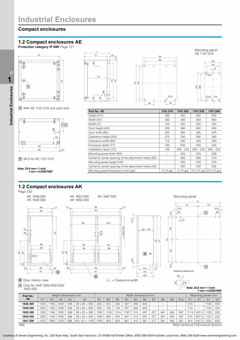
1.2 Compact enclosures AEProtection category IP 69K Page 121
B425T1
T
2.5B1
Mounting panelAE 1101.010
With AE 1101.010 one cam lock1PH
58.5 for AE 1101.010 1
art No. AE 1101.010 1101.020 1101.030 1101.04eight (H1) 330 400 650 650
Width (B1) 230 400 400 650
Depth (T) 155 250 250 250
Door height (H2) 325 395 645 645
Door width (B2) 225 395 395 645
Clearance height (H3) 270 340 590 590
Clearance width (B3) 170 340 340 590
Enclosure depth (T1) 130 225 225 225
Installation depth (T2) 135 208 – 224 208 – 224 208 – 2
Mounting panel width (B4) – 334 334 549
Center-to-center spacing of the attachment holes (B5) 295 295 510
Mounting panel height (H4) – 355 570 570
Center-to-center spacing of the attachment holes (H5) 330 545 545
Mounting panel thickness in mm (ga) 2 (14 ga) 2 (14 ga) 2.5 (12 ga) 2.5 (12
1.2 Compact enclosures AKPage 122
Mounting panel AK 1646.500 AK 1652.500 AK 1647.500
AK 1648.500 AK 1650.500F1
12 1
50
Holes for eyebolts (2x)
Door interior view
Only for 1647.500/1650.500/ 1652.500
X
1
1086 Rittal Handbook 31/Enclosure Systems
Part No. AK
Height dimensions mm Width dimensions mm Mounting panels mm
H1 H2 H3 H4 H5 B1 B2 B3 B4 B5 B6 B7 B8 B9 B10 F1 F2 G1 G2
1646.500 1200 1166 1092 568 38 x 25 = 950 600 500 524 597 459 443 – – – – 514 – 1125 550
1648.500 1200 1166 1092 568 38 x 25 = 950 800 700 724 797 659 643 – – – – 714 – 1125 550
1652.500 1200 1166 1092 568 38 x 25 = 950 1200 1100 1124 1197 513 497 477 461 595 597 1114 537.5 1125 550
1650.500 1200 1166 1092 568 38 x 25 = 950 1000 900 924 997 413 397 377 361 495 497 914 437.5 1125 550
1647.500 1400 1366 1292 668 46 x 25 = 1150 1000 900 924 997 413 397 377 361 495 497 914 437.5 1325 650
1 mm = 0.03937008″
Compact enclosures
Industrial Enclosures
1087Rittal Handbook 31/Enclosure Systems
C
1.
Indu
stria
l Enc
losu
res
R 35
B4
B652
B2
B7
B1
B3
B5H
3
H4
100
H6
H5
B8
1 2
X
4.5
H2
H1
H7
25
T1
m1
m2
3
T4
T3
12.5
42.5
42.5
12.5
12.5
3
m3
17.5
G1
10
50
10.
5
F1
16
60
10.5
8.5
Note: 25.4 mm = 1 inch
Courtesy of Steven Engineering, Inc.-230 Ryan Way, South San Francisco, CA 94080-6370-Main Office: (650) 588-9200-Outside Local Area: (800) 258-9200-www.stevenengineering.com
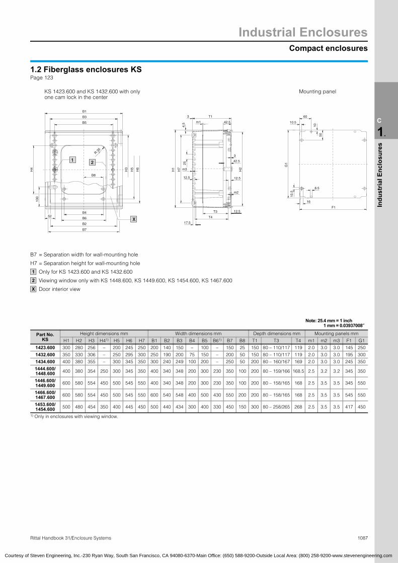
1.2 Fiberglass enclosures KSPage 123
KS 1423.600 and KS 1432.600 with only one cam lock in the center
Mounting panel
B7 = Separation width for wall-mounting hole
H7 = Separation height for wall-mounting hole
Only for KS 1423.600 and KS 1432.600
Viewing window only with KS 1448.600, KS 1449.600, KS 1454.600, KS 1467.600
Door interior view
1
2
X
Part No. KS
Height dimensions mm Width dimensions mm Depth dimensions mm Mounting panels mm
H1 H2 H3 H41) H5 H6 H7 B1 B2 B3 B4 B5 B61) B7 B8 T1 T3 T4 m1 m2 m3 F1 G1
1423.600 300 280 256 – 200 245 250 200 140 150 – 100 – 150 25 150 80 – 110/117 119 2.0 3.0 3.0 145 250
1432.600 350 330 306 – 250 295 300 250 190 200 75 150 – 200 50 150 80 – 110/117 119 2.0 3.0 3.0 195 300
1434.600 400 380 355 – 300 345 350 300 240 249 100 200 – 250 50 200 80 – 160/167 169 2.0 3.0 3.0 245 350
1444.600/ 1448.600 400 380 354 250 300 345 350 400 340 348 200 300 230 350 100 200 80 – 159/166 168.5 2.5 3.2 3.2 345 350
1446.600/ 1449.600 600 580 554 450 500 545 550 400 340 348 200 300 230 350 100 200 80 – 158/165 168 2.5 3.5 3.5 345 550
1466.600/ 1467.600 600 580 554 450 500 545 550 600 540 548 400 500 430 550 200 200 80 – 158/165 168 2.5 3.5 3.5 545 550
1453.600/1454.600 500 480 454 350 400 445 450 500 440 434 300 400 330 450 150 300 80 – 258/265 268 2.5 3.5 3.5 417 450
1) Only in enclosures with viewing window.
1 mm = 0.03937008″

Industrial EnclosuresCompact enclosures
1088 Rittal Handbook 31/Enclosure Systems
C
1.
Indu
stria
l Enc
losu
res
72
25
R 90
H3
H4 H6
H5
50
B2
B6
B4X
A – A
267
H1
12.5
m2
H2
3
3
m3
12.5
H7
80 – 2541)/2642)
7
300
ZZ 33.5
50 10
10.5
17.5
10.5
16
8.5
G1
F1
AB
60
H3
H6
H5
497.5
B2
B4
497.5
B2
B4
50
41 41B3
B5
A X
Y
240
Note: 25.4 mm = 1 inch
Courtesy of Steven Engineering, Inc.-230 Ryan Way, South San Francisco, CA 94080-6370-Main Office: (650) 588-9200-Outside Local Area: (800) 258-9200-www.stevenengineering.com
1.2 Fiberglass enclosures KSPage 124
27 40
B1
B3
B5
KS 1469.600/KS 1479.600 KS 1468.600/KS 1480.600 without viewing window
60
Mounting panel
B1
KS 1400.600
1) Infinitely variable with mountingpanel depth adjuster KS 1491.0002) When mounting on studs
directly on the threaded insert
B7 = Separation width for wall-mounting hole
H7 = Separation height for wall-mounting hole
Door interior view
Screw-fastened center bar for KS 1400.000
Distance from mounting insert to center bar
X
Y
Z
Y
ZPart No. KSHeight dimensions mm Width dimensions mm Mounting panel dimensions
H1 H2 H3 H41) H5 H6 H7 B1 B2 B3 B4 B5 B61) B7 m2 m3 G1 F1
1468.600/1469.600 800 780 753 590 700 740 750 600 485 533 400 500 410 550 3.7 3.7 750 517
1479.600/1480.600 1000 980 953 790 900 940 950 800 685 733 600 700 610 750 3.7 4.0 950 717
1400.600 1000 980 952 – 900 940 950 1000 387 918 300 900 – 950 3.5 4.0 950 9171) Only in enclosures with viewing window.
1 mm = 0.03937008″

Large enclosures
Industrial Enclosures
1089Rittal Handbook 31/Enclosure Systems
C
1.
Indu
stria
l Enc
losu
res
Ø 4.6
Ø 9
25.5
H2
3
M6
4 x
25 =
100
98i.L
. H7
H6
H8
72i.L. B6
B7
72
B1
B8
H9
98i.L
. H7
H6
H8
H9
Ø 4.6
Ø 9
25.5
H2
3
M 6
4 x
25 =
100
i.L. B6
B772 i.L. B6
B772
B8
B1
33.5
63.5
20 203
25.5
30
T5
T4
T1
38.5 T7 38.5
T6 – 149 2
i.L. H
3
H2
45
53
46.5
54.5
G H5
25
65
H1
Ø 16
99
50
T1
T2
63.5
63.5
2525
62B562
i.L. B9
F
30
B2
99
50
i.L. B3
30
Ø 16
B28B2
i.L. B3
i.L. B9 39 i.L. B9
F
99
50
99
50
T1
T2
63.5
63.5
2525
62 B5 62
3030Y
89
1.4 Freestanding enclosure ES 5000Painted Pages 136, 137
Stainless steel Page 285
i.L. = Clearance width
Courtesy of Steven Engineering, Inc.-230 Ryan Way, South San Francisco, CA 94080-6370-Main Office: (650) 588-9200-Outside Local Area: (800) 258-9200-www.stevenengineering.com
Detail Y(only with ES 5784.500 and ES 5905.500)
20.5
793 or 893
793 or 893Double door
Part No. ES Height dimensions mm Width dimensions mm Depth dimensions mmMounting
paneldimensions
Painted Stainless steel H1 H2 H3 H5 H6 H7 H8 H9 B1 B2 B3 B5 B6 B7 B8 B9 T1 T2 T4 T5 T6 T7 F G
5080.500 – 1810 1775 1712 1675 1650 1630 1600 898 999 492 912 875 355 375 935 801 402 275 349 269 349 325 899 1696
5265.500 – 1610 1575 1512 1475 1450 1430 1400 798 1199 592 1112 1075 455 475 1135 481 502 375 449 369 449 425 1099 1496
5284.500 – 1810 1775 1712 1675 1650 1630 1600 898 1199 592 1112 1075 455 475 1135 481 402 275 349 269 349 325 1099 1696
5205.500 5455.600 2010 1975 1912 1875 1850 1830 1800 998 1199 592 1112 1075 455 475 1135 481 502 375 449 369 449 425 1099 1896
5784.500 – 1810 1775 1712 1675 1650 1630 1600 898 1599 792 1512 1475 655 675 1535 681 402 275 349 269 349 325 1499 1696
5905.500 – 2010 1975 1912 1875 1850 1830 1800 998 1799 892 1712 1675 755 775 1735 781 502 375 449 369 449 425 1699 1896
Note: 25.4 mm = 1 inch1 mm = 0.03937008″

Industrial EnclosuresLarge enclosures
1090 Rittal Handbook 31/Enclosure Systems
C
1.
Indu
stria
l Enc
losu
res
23
G
24.5
4873
17
42
23
23
24.5
10.
12.5 4.5
11.8
44.3
20.5
Courtesy of Steven Engineering, Inc.-230 Ryan Way, South San Francisco, CA 94080-6370-Main Office: (650) 588-9200-Outside Local Area: (800) 258-9200-www.stevenengineering.com
1.4 Freestanding enclosure ES 5000Painted Pages 136, 137
Stainless steel Page 285
F
Mounting panel
EnclosureMounting panel
B1 =B2 =B3 =
B5 =
B6 =
B7 =
B8 =B9 =
H1 =H2 =H3 =
H5 =H6 =
H7 =
H8 =
H9 =
T1 =T2 =
T4 =T5 =T6 =
T7 =
Overall widthWidth of doorClearance between enclosure frame sectionsSection length of system punchings/hole distance of base and plinth attachmentClearance between the tubular door frame sectionsDistance between the rows of tubular door frame holes Spacing between eyeboltsClearance in base aperture
Overall heightHeight of rear panel and doorClearance between enclosure frame sectionsSection length of system punchingsDistance between the rows of tubular door frame holes Clearance between the tubular door frame sectionsSpacing of tubular door frame fastening boltsDistance from base to center of lock
Overall depthSection length of system punchings/holedistance of base and plinth attachmentDepth of base frameClearance in base aperturePossible mounting depth (mounting panel assembly) up to 149 mm (5.9″), Depth-adjustable on a 25 mm (1.0″) system hole patternCenter-to-center distance between eyebolts
F = G =
Overall widthOverall height
Cross-section
11.8
23.5
5
12.5
25
System hole pattern
Single door
Part No. ES Height dimensions mm Width dimensions mm Depth dimensions mmMounting
paneldimensions
Painted Stainless steel H1 H2 H3 H5 H6 H7 H8 H9 B1 B2 B3 B5 B6 B7 B8 B9 T1 T2 T4 T5 T6 T7 F G
– 5450.600 1610 1575 1512 1475 1450 1430 1400 798 599 592 512 475 455 475 535 401 402 275 349 269 349 325 499 1496
5665.500 – 1610 1575 1512 1475 1450 1430 1400 798 599 592 512 475 455 475 535 401 502 375 449 369 449 425 499 1496
5684.500 – 1810 1775 1712 1675 1650 1630 1600 898 599 592 512 475 455 475 535 401 402 275 349 269 349 325 499 1696
– 5451.600 1810 1775 1712 1675 1650 1630 1600 898 599 592 512 475 455 475 535 401 502 375 449 369 449 425 499 1696
5605.500 – 2010 1975 1912 1875 1850 1830 1800 998 599 592 512 475 455 475 535 401 502 375 449 369 449 425 499 1896
5865.500 – 1610 1575 1512 1475 1450 1430 1400 798 799 792 712 675 655 675 735 601 502 375 449 369 449 425 699 1496
5884.500 – 1810 1775 1712 1675 1650 1630 1600 898 799 792 712 675 655 675 735 601 402 275 349 269 349 325 699 1696
5805.500 – 2010 1975 1912 1875 1850 1830 1800 998 799 792 712 675 655 675 735 601 502 375 449 369 449 425 699 1896
5084.500 5454.600 1810 1775 1712 1675 1650 1630 1600 898 999 992 912 875 855 875 935 801 402 275 349 269 349 325 899 1696
– 5452.600 1810 1775 1712 1675 1650 1630 1600 898 799 792 712 675 655 675 735 601 502 375 449 369 449 425 699 1696
– 5453.600 2010 1975 1912 1875 1850 1830 1800 998 799 792 712 675 655 675 735 601 602 475 549 469 549 525 699 1896
Note: 25.4 mm = 1 inch1 mm = 0.03937008″

Large enclosures
Industrial Enclosures
1091Rittal Handbook 31/Enclosure Systems
C
1.
Indu
stria
l Enc
losu
res
i.L. T3
35 35T7
i.L. H
3
H2
H1
463.5
444.5
64.5
30
H5
32.5
62.5i.L. T5
T4
G
5551
25
T6 2
17
T1
H9
H8
i.L. H
7
H6
96
71
i.L. B5
B6
71
22
H4
2.5
B7
B1
4 x
25 (
= 1
00)
Ø 4.6Ø 9
M6
60
H6
i.L. H
7
H8
H9
96
71
60
H4
222.
5
71
B6
i.L. B5
Ø 6
4 x
25 (
= 1
00)
Ø 9
M6
B6
i.L. B5
B1
B7
3030
T2
6565
T1
49 F 49
i.L. B8Ø 1678.5
78.5
30 30
B4
46.5
i.L. T
346
.5i.L. B3
61 61
M12
1815
T1
T2
78.5
65
30
Ø 16
61
30
49
65
30
i.L. T
346
.5
78.5
M12
46.5
61
30
49
B4
F
i.L. B8
i.L. B3
i.L. B8
1815
1
1.4 TS8 modular enclosure systemPainted Pages 138 – 147
Stainless steel Page 284
Courtesy of Steven Engineering, Inc.-230 Ryan Way, South San Francisco, CA 94080-6370-Main Office: (650) 588-9200-Outside Local Area: (800) 258-9200-www.stevenengineering.com
B2
Base/plinth-mounting: B4 x T2
B2
Base/plinth-mounting: B4 x T2
Note:With fitted sidewalls, the overall width (B1) is increased by 9 mm (0.4″). Between bayed enclo-sures, allow 3 mm (0.1″) for the seal.
Does not apply to TS 8880.500/TS 8881.500
1
i.L. = Clearance width
Double door
Part No. TS Height dimensions mm Width dimensions mm Depth dimensions mmMounting
panel dimensions
Painted Stainless steel H1 H2 H3 H4 H5 H6 H7 H8 H9 B1 B2 B3 B4 B5 B6 B7 B8 T1 T2 T3 T4 T5 T6 T7 F G
8245.500 – 1405139713121377.51275125012301200 711 1197119211121075 455 475 1135 500 505 375 412 468 340 130 – 455 435 1099 1296
8080.500 – 1805179717121777.51675165016301600 911 997 992 912 875 355 375 935 400 405 275 312 368 240 130 – 355 335 899 1696
8284.500 8456.600 1805179717121777.51675165016301600 911 1197119211121075 455 475 1135 500 405 275 312 368 240 130 – 355 335 1099 1696
8880.500 – 1805179717121777.51675165016301600 911 797 792 712 675 255 275 735 640 505 375 412 468 340 130 – 455 435 699 1696
8285.500 8453.600 1805179717121777.51675165016301600 911 1197119211121075 455 475 1135 500 505 375 412 468 340 130 – 455 435 1099 1696
8881.500 – 1805179717121777.51675165016301600 911 797 792 712 675 255 275 735 640 605 475 512 568 440 130 – 555 535 699 1696
8286.500 – 1805179717121777.51675165016301600 911 1197119211121075 455 475 1135 500 605 475 512 568 440 130 – 555 535 1099 1696
8204.500 – 2005199719121977.5187518501830180010111197119211121075 455 475 1135 500 405 275 312 368 240 130 – 355 335 1099 1896
8005.500 – 2005199719121977.518751850183018001011 997 992 912 875 355 375 935 400 505 375 412 468 340 130 – 455 435 899 1896
8205.500 – 2005199719121977.5187518501830180010111197119211121075 455 475 1135 500 505 375 412 468 340 130 – 455 435 1099 1896
8006.500 – 2005199719121977.518751850183018001011 997 992 912 875 355 375 935 400 605 475 512 568 440 130 – 555 535 899 1896
8206.500 8451.600 2005199719121977.5187518501830180010111197119211121075 455 475 1135 500 605 475 512 568 440 130 – 555 535 1099 1896
8208.500 – 2005199719121977.5187518501830180010111197119211121075 455 475 1135 500 805 675 712 768 640 130 – 755 735 1099 1896
8226.500 – 2205219721122177.5207520502030200011111197119211121075 455 475 1135 500 605 475 512 568 440 130 – 555 535 1099 2096
8265.500 – 1605159715121577.51475145014301400 – 1197119211121075 455 475 1135 500 505 375 412 468 340 130 – 455 435 1099 1496
Note: 25.4 mm = 1 inch1 mm = 0.03937008″

Industrial EnclosuresLarge enclosures
C
1.
Indu
stria
l Enc
losu
res
73 48 24.5
23
17 23
F
42
24.5
G
2325
12.5 4
25 12.5
4.5
i.L. (
T3)
i.L. (B3)
42.5
42.5
i.L. (
H3)
i.L. (B3/T3)
42.5 12
.5
11.5
4.5
12.5
12.5 4
10.525
20
Mounting panel
i.L. = Clearance width
Courtesy of Steven Engineering, Inc.-230 Ryan Way, South San Francisco, CA 94080-6370-Main Office: (650) 588-9200-Outside Local Area: (800) 258-9200-www.stevenengineering.com
6.5
42.5
Cross-sectionsvertical
Horizontal
Enclosure
Mounting panel
B1 =B2 =B3 =
B4 =
B5 =
B6 =
B7 =B8 =
H1 =H2 =H3 =H4 =H5 =H6 =
H7 =
H8 =
H9 =T1 =T2 =
T3 =
T4 =T5 =T6 =
T7 =
Overall widthWidth of doorClearance between enclosure frame sectionsSection length of system punchings/hole distance of base and plinth attachmentClearance between the tubular door frame sectionsDistance between the rows of tubular door frame holes Spacing between eyeboltsClearance in base opening
Overall heightHeight of rear panelClearance between enclosure frame sectionsHeight of doorSection length of system punchingsDistance between the rows of tubular door frame holes Clearance between the tubular door frame sectionsSpacing of tubular door frame fastening boltsDistance from base to center of lockOverall depthSection length of system punchings/hole distance of base and plinth attachmentClearance between enclosure frame sectionsDepth of base frameClearance in base aperturePossible mounting depth (mounting panel assembly), depth-adjustable on a 25 mm (1.0″) system hole pattern Center-to-center distance between eyebolts
F = G =
Overall widthOverall height
Depth dimensions mmMounting
panel dimensions
7 B8 T1 T2 T3 T4 T5 T6 T7 F G
Note: 25.4 mm = 1 inch1 mm = 0.03937008″
1092 Rittal Handbook 31/Enclosure Systems
Single door
Part No. TS Height dimensions mm Width dimensions mm
Painted Stainless steel H1 H2 H3 H4 H5 H6 H7 H8 H9 B1 B2 B3 B4 B5 B6 B
8645.500 – 1405 1397 1312 1377.5 1275125012301200 711 597 592 512 475 455 475 535 440 505 375 412 468 340 130 – 455 435 499 1296
8845.500 – 1405 1397 1312 1377.5 1275125012301200 711 797 792 712 675 655 675 735 640 505 375 412 468 340 130 – 455 435 499 1296
8684.500 – 1805 1797 1712 1777.5 1675165016301600 911 597 592 512 475 455 475 535 440 405 275 312 368 240 130 – 355 335 499 1696
8884.500 8454.600 1805 1797 1712 1777.5 1675165016301600 911 797 792 712 675 655 675 735 640 405 275 312 368 240 130 – 355 335 699 1696
8084.500 – 1805 1797 1712 1777.5 1675165016301600 911 997 992 912 875 855 875 935 840 405 275 312 368 240 130 – 355 335 899 1696
8485.510 – 1805 1797 1712 1777.5 1675165016301600 911 397 392 312 275 255 275 335 240 505 375 412 468 340 130 – 455 435 – –
8685.500 8457.600 1805 1797 1712 1777.5 1675165016301600 911 597 592 512 475 455 475 535 440 505 375 412 468 340 130 – 455 435 499 1696
8885.500 8455.600 1805 1797 1712 1777.5 1675165016301600 911 797 792 712 675 655 675 735 640 505 375 412 468 340 130 – 455 435 699 1696
8486.510 – 1805 1797 1712 1777.5 1675165016301600 911 397 392 312 275 255 275 335 240 605 475 512 568 440 130 – 555 535 – –
8686.500 – 1805 1797 1712 1777.5 1675165016301600 911 597 592 512 475 455 475 535 440 605 475 512 568 440 130 – 555 535 499 1696
8886.500 – 1805 1797 1712 1777.5 1675165016301600 911 797 792 712 675 655 675 735 640 605 475 512 568 440 130 – 555 535 699 1696
8604.500 – 2005 1997 1912 1977.5 18751850183018001011 597 592 512 475 455 475 535 440 405 275 312 368 240 130 – 355 335 499 1896
8804.500 – 2005 1997 1912 1977.5 18751850183018001011 797 792 712 675 655 675 735 640 405 275 312 368 240 130 – 355 335 699 1896
8405.510 – 2005 1997 1912 1977.5 18751850183018001011 397 392 312 275 255 275 335 240 505 375 412 468 340 130 – 455 435 – –
8605.500 – 2005 1997 1912 1977.5 18751850183018001011 597 592 512 475 455 475 535 440 505 375 412 468 340 130 – 455 435 499 1896
8805.500 – 2005 1997 1912 1977.5 18751850183018001011 797 792 712 675 655 675 735 640 505 375 412 468 340 130 – 455 435 699 1896
8406.510 – 2005 1997 1912 1977.5 18751850183018001011 397 392 312 275 255 275 335 240 605 475 512 568 440 130 – 555 535 – –
8606.500 8452.600 2005 1997 1912 1977.5 18751850183018001011 597 592 512 475 455 475 535 440 605 475 512 568 440 130 – 555 535 499 1896
8806.500 8450.600 2005 1997 1912 1977.5 18751850183018001011 797 792 712 675 655 675 735 640 605 475 512 568 440 130 – 555 535 699 1896
8608.500 – 2005 1997 1912 1977.5 18751850183018001011 597 592 512 475 455 475 535 440 805 675 712 768 640 130 – 755 735 499 1896
8808.500 – 2005 1997 1912 1977.5 18751850183018001011 797 792 712 675 655 675 735 640 805 675 712 768 640 130 – 755 735 699 1896
8626.500 – 2205 2197 2112 2177.5 20752050203020001111 597 592 512 475 455 475 535 440 605 475 512 568 440 130 – 555 535 499 2096
8826.500 – 2205 2197 2112 2177.5 20752050203020001111 797 792 712 675 655 675 735 640 605 475 512 568 440 130 – 555 535 699 2096
8665.500 – 1605 1597 1512 1577.5 1475145014301400 – 597 592 512 475 455 475 535 440 505 375 412 468 340 130 – 455 435 499 1496
8865.500 – 1605 1597 1512 1577.5 1475145014301400 – 797 792 712 675 655 675 735 640 505 375 412 468 340 130 – 455 435 699 1696
Large enclosures
Industrial Enclosures
1093Rittal Handbook 31/Enclosure Systems
C
1.
Indu
stria
l Enc
losu
res
H1
i.L. H
344
H2
4.5
42.5
35.5
H5
i.L. T5
T4
5551
25
T6 2
17
T1
12.5
1
3030
T2
6565
T1
49 699 49
i.L. 640Ø 1678.5
78.5
30 30
46.5
i.L. T
346
.5i.L. 712
67561 61
M12
1815
592 192
X34
0.5
93
90.5
71
i.L. 455i.L. 455
475
22
Ø 9
M6
Ø 4.6
H9
H8
i.L. H
796
H6
H4
4 x
25
(= 1
00)
12.7
119
.1
25.
4 2
2.2
25.
4
14.3
i.L. = Clearance width
Courtesy of Steven Engineering, Inc.-230 Ryan Way, South San Francisco, CA 94080-6370-Main Office: (650) 588-9200-Outside Local Area: (800) 258-9200-www.stevenengineering.com
i.L. T3
3535 T7
463.5
772.560
735
797
7.1
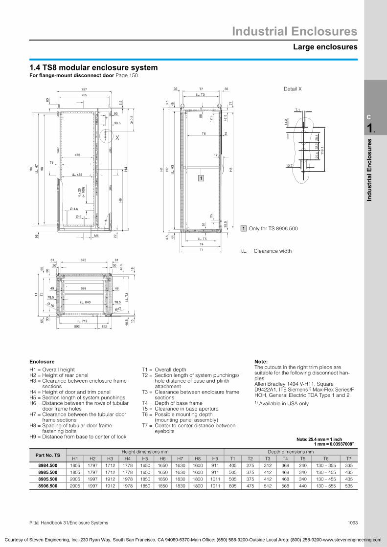
1.4 TS8 modular enclosure systemFor flange-mount disconnect door Page 150
Detail X
Only for TS 8906.5001
Enclosure Note:The cutouts in the right trim piece are suitable for the following disconnect han-dles: Allen Bradley 1494 V-H11, Square D9422A1, ITE Siemens1) Max-Flex Series/F HOH, General Electric TDA Type 1 and 2. 1) Available in USA only.
H1 =H2 =H3 =
H4 =H5 =H6 =
H7 =
H8 =
H9 =
Overall heightHeight of rear panelClearance between enclosure frame sectionsHeight of door and trim panelSection length of system punchingsDistance between the rows of tubular door frame holes Clearance between the tubular door frame sectionsSpacing of tubular door frame fastening boltsDistance from base to center of lock
T1 =T2 =
T3 =
T4 =T5 =T6 =
T7 =
Overall depthSection length of system punchings/hole distance of base and plinthattachmentClearance between enclosure frame sectionsDepth of base frameClearance in base aperturePossible mounting depth(mounting panel assembly) Center-to-center distance between eyebolts
Note: 25.4 mm = 1 inch1 mm = 0.03937008″
Part No. TSHeight dimensions mm Depth dimensions mm
H1 H2 H3 H4 H5 H6 H7 H8 H9 T1 T2 T3 T4 T5 T6 T7
8984.500 1805 1797 1712 1778 1650 1650 1630 1600 911 405 275 312 368 240 130 – 355 335
8985.500 1805 1797 1712 1778 1650 1650 1630 1600 911 505 375 412 468 340 130 – 455 435
8905.500 2005 1997 1912 1978 1850 1850 1830 1800 1011 505 375 412 468 340 130 – 455 435
8906.500 2005 1997 1912 1978 1850 1850 1830 1800 1011 605 475 512 568 440 130 – 555 535

Industrial EnclosuresLarge enclosures
1094 Rittal Handbook 31/Enclosure Systems
C
1.
Indu
stria
l Enc
losu
res
1605
/200
5
535/735
1512
/191
2
1466
.6 (
33 H
E)/
1866
.9 (
42 H
E)
465
� 9
.5
44.4
5 31.7
5
7.6
452
452
63
43 48653
592
592
512/
712
512
622/
822
1.4 TS8 modular enclosure systemElectronic enclosures Page 148
HE = U
601.5
12.5
25
568
i.L. 440
77
42.5
4.5 44
3.5
46
2005
1997
i.L. 1
912
535 3135
i.L. 512
7718
50
597/797
18
M12
6161
512/712
42.5
i.L. 5
1246
.5
475/675
3030
Ø 16
601.
565
6547
5
3030
25 12.5
6.5
25
4.5
12.5 4
42.5
42.5
i.L.
42.5
42.5
i.L.
i.L. 10.5
20
11.5
4
12.5
4.5
12.5
12.5
25
60
597/797
535/735
i.L. = Clearance width
Note: 25.4 mm = 1 inch1 mm = 0.03937008″
Courtesy of Steven Engineering, Inc.-230 Ryan Way, South San Francisco, CA 94080-6370-Main Office: (650) 588-9200-Outside Local Area: (800) 258-9200-www.stevenengineering.com
1.4 TS8 modular enclosure systemFor modular front design Page 149
Cross-sections
Vertical Horizontal
i.L.
Operating housings
Industrial Enclosures
Rittal Handbook 31/Enclosure Systems
C
1.
Indu
stria
l Enc
losu
res
Y
17171)
5
4
Y
X17
143
2
1
3
68
33
B8 (B1 + 25)
B5 (B1 – 33) 173
(176
)
31 (
34)
6880
2
1
B5 (B1 – 33)
B4 (B1 – 8)
B1
H1
H2
(H1
+ 1
33)
H6
(H1
+ 1
2)
H5
(H1 –
33)
B2 (B1 + 133)
H4
(H1
– 8)
B2 (B1 + 77)
H2
(H1
+ 7
7)
B2 (B1 + 88)
H2
(H1
+ 7
7)
7
Ø 70
Ø 82
80
112
Ø 100
205
(208
)
68
113
1
max
. ins
talla
tion
epth
155
mm
(6.1
″)
Courtesy of Steven Engineering, Inc.-230 Ryan Way, South San Francisco, CA 94080-6370-Main Office: (650) 588-9200-Outside Local Area: (800) 258-9200-www.stevenengineering.com
1.5 Rittal Command Panel VIP 60003.1 Installation depth Page 161
B6 (B1 + 12)
Front frame, wide Narrow Combined
155 mm (6.1″)1 B3 (with fins/partial fins: B1 + 85 mm (3.3″))
B3 (without fins: B1 + 55 mm (2.2″))
B7 (B1 + 43)
d
Dimensions in brackets refer to narrow and combined front frames.
Cross section of the cable duct1
Support arm connections
CP-L, Ø 130 mm (5.1″) CP-XL
7
Ø185 mm (7.3″), screw-fastened2
Support arm cutout for CP-L system, Ø 130 mm (5.1″)2
Dimensions in brackets refer to narrow and combined front frames.
Support arm connection for system Ø 131
0 mm (5.1″)max
. ins
talla
tion
dept
h 18
5 m
m (7
.3″)
185 mm (7.3″), hinged3
4
max
. 130
°
X
Support arm connection for CP-L system, Ø 130 mm (5.1″)Only for CP 6392.109, CP 6392.209
Only for CP 6392.009
Max. installation space for hinged enclosures
Collision zone
1
2
3
4
5
1095
B1
1) See page 160.
Width dimensions: B1 = Width of the front panelB2 = Overall widthB3 = Enclosure widthB4 = Clearance width between
enclosure sectionsB5 = Clearance width between
retaining clamps of the mounting kit
B6 = Clearance width between the front frames
B7 = Width of the rear panelB8 = Internal clearance of enclosure,
width
HeH1H2H3
H4
H5
H6
H7
H8
ight dimensions: = Height of the front panel= Overall height= Enclosure height
(with fins: H1 + 85 mm (3.3″),without fins: H1 + 55 mm (2.2″))
= Clearance height between enclosure sections
= Clearance height between retaining clamps
= Clearance height between front frames
= Height of the rear panel (H1 + 43 mm (1.7″))
= Internal clearance of enclosure,height (H1 + 25 mm (1.0″))
max
. ins
talla
tion
dept
h
Industrial EnclosuresOperating housings
109 k 31/Enclosure Systems
C
1.
Indu
stria
l Enc
losu
res
458
(461
)
222
364
3
316
(319
)
222
210
1
Y
17
X
4
134
8 (3
51)
254 22
2
3
X
17
Y3
2
5
4
X
Y
17
3
650 700 750
Y
X
650 700 750
Y
X
Courtesy of Ste South San Francisco, CA 94080-6370-Main Area: (800) 258-9200-www.stevenengineering.com
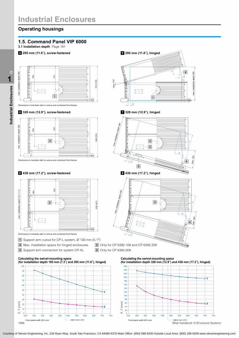
1.5. Command Panel VIP 60003.1 Installation depth Page 161
295 mm (11.6″), screw-fastened4 295 mm (11.6″), hinged5
max
. ins
talla
tion
dept
h 29
5
max
. 170
°
max
. ins
talla
tion
dept
h 29
5
Dimensions in brackets refer to narrow and combined front frames.
328 mm (12.9″), screw-fastened6
max
. ins
talla
tion
dept
h 32
8
Dimensions in brackets refer to narrow and combined front frames.
328 mm (12.9″), hinged7
max. i
nsta
llatio
n de
pth
328
max
. 130
°
438 mm (17.2″), screw-fastened8
max
. ins
talla
tion
dept
h 43
8 (1
7.2)
Dimensions in brackets refer to narrow and combined front frames.
Support arm cutout for CP-L system, Ø 11
438 mm (17.2″), hinged9
max
. ins
talla
tion
dept
h 43
8
4
max
. 160
°
30 mm (5.1″)
Max. installation space for hinged enclosures
Support arm connection for system CP-XL
4
3
Only
Only
2
5
Calculating the swivel-mounting spac
for CP 6392.109 and CP 6392.209
for CP 6392.009
6
300250 350 400 450 500 550 600
482.6 mm (19˝)Front panel width (B1) mm
Rittal Handboo300250 350 400 450 500 550 600
482.6 mm (19˝)Front panel width (B1) mm
100
Calculating the swivel-mounting space(for installation depth 185 mm (7.3″) and 295 mm (11.6″), hinged)
260
e(for installation depth 328 mm (12.9″) and 438 mm (17.2″), hinged)
90
80
70
60
50
40
30
20
10
0X, Y
(m
m)
ven Engineering, Inc.-230 Ryan Way,
180
200
220
240
160
140
120
100
80
60
40
20
0X, Y
(m
m)
Office: (650) 588-9200-Outside Local

Operating housings
Industrial Enclosures
1097Rittal Handbook 31/Enclosure Systems
C
1.
Indu
stria
l Enc
losu
res
3
2
20
2
4
438 (17.2)
Screw-fastened
Hinged
265 (10.4)
9
6 6
66.5
6176 17
.5
Courtesy of Steven Engineering, Inc.-230 Ryan Way, South San Francisco, CA 94080-6370-Main Office: (650) 588-9200-Outside Local Area: (800) 258-9200-www.stevenengineering.com
1.5 Rittal Command Panel VIP 60003.2 Front design Page 162
1
Cross member1 3 5
H1
top
17 28.5
H1
botto
m
Sealing bar2 4 5
Front panel 11
1
H1
top
H1
botto
m
Front panel 2
Cross member
Sealing bar
2
3
4
Minimum front panel width (B1)Depending on the:● Installation depth of the operating housing● Connection between the operating housing/keyboard housing● Position of the support arm connection
Dimensionsmm (inches)
Installation depth of operating housing mm (inches) (see page 161)
155 (6.1) 185 (7.3) 295 (11.6) 328 (12.9)
Prepared for the external-mounting of keyboard housing
(see design code number 3.7, page 164)
Support arm/wall-mounted and
pedestal connection (see design code
number 3.6, page 164)
Screw-fastened Screw-fastened Screw-fastened
Hinged Hinged Hinged
0 None0 to 3top orbottom
Minimum front panel width mm (inches)
169 (6.7) 265 (10.4) 169 (6.7) 265 (10.4)
1 Frame connector or 4 hinged
frame connector
1 top 169 (6.7) 265 (10.4) 169 (6.7) 265 (10.4)
2 and 3bottom 339 (13.3)1) 445 (17.5)1) 339 (13.3)1) 445 (17.5)1)
2 Enclosure duct connector
1 top 189 (7.4) 265 (10.4) 189 (7.4) 265 (10.4)
2 and 3bottom 339 (13.3) 445 (17.5) 339 (13.3) 445 (17.5)
3 Enclosure bar connector
1 top 169 (6.7) 265 (10.4) 169 (6.7) 265 (10.4)
2 and 3bottom 397 (15.6)1) 445 (17.5)1) 397 (15.6)1) 445 (17.5)1)
1) Smaller front panel widths for asymmetrical support arm connection available on request.
1 2 4 6 8
3 5 7
3.4 Trim types Page 163
Cover trim 1 End trim 2
B1/H1B1/H1
Front panel recessed, screws concealed
B1/H1 B1/H1Front panel recessed
6
max
. 3.5
6
max
. 3.5
varia
ble
A
varia
ble
B1/H1 B1/H1
Spacer trim Front panel flush3
Mounting kitfor threaded bolts: M5: CP 6053.500M4: CP 6058.500
Mounting kitfor screw clamp: CP 6053.210
Mounting kits,
ssembly kitfor holes:M5: CP 6053.000M4: CP 6058.000M6: CP 6053.000/6058.000+ EL 2092.200+ screws M6 x 25 (1.0″)
see page 1037.
max
. 3.5
max
. 3.5

Industrial EnclosuresKeyboard housing
1098 Rittal Handbook 31/Enclosure Systems
C
1.
Indu
stria
l Enc
losu
res
B1
B4 (B1 + 12)
B2 (B1 + 133)
B3 (B1 + 61)
B1
92
B2 (B1 + 77)
B1
1 + 88)
92
X
30°
H6 (H1 + 43)H3 (H1 + 61)
H1 x 0.87 + 123
H2 (H1 + 133)H1H5 (H1 – 8)
H4 (H1 + 12)
H1
x 0.
5 +
138
1
2
87
22
X
H1 x 0.87 + 74
.5 +
138
H6 (H1 + 43)H3 (H1 + 61)
H2 (H1 + 77)H1H5 (H1 – 8)
H4 (H1 + 12)
30°
1
2
87
22
X
H1 x 0.87 + 74
H1
x 0.
5 +
138
H6 (H1 + 43)H3 (H1 + 61)
H2 (H1 + 77)H1H5 (H1 – 8)
H4 (H1 + 12)
30°
1
2
B = Width
Courtesy of Steven Engineering, Inc.-230 Ryan Way, South San Francisco, CA 94080-6370-Main Office: (650) 588-9200-Outside Local Area: (800) 258-9200-www.stevenengineering.com
1.5 Rittal Command Panel VIP 60004.1 Keyboard housing Page 166
Installation depth 105 mm (4.1″)1
Front framesWide
123
max
.in
stalla
tion
dept
h10
5 (5
.1)
Narrow
126
max
.in
stalla
tion
dept
h10
5 (5
.1)
B2 (B
Combined
H1
x 0
126
max
.in
stalla
tion
dept
h10
5 (5
.1)
Frame connector,rigid/adjustable
CP 6058.XXX: M4CP 6053.XXX: M5
1
2
Enclosure duct connector
CP 6058.XXX: M4CP 6053.XXX: M5
1
2
Enclosure duct connector
CP 6058.XXX: M4CP 6053.XXX: M5
1
2

Keyboard housing
Industrial Enclosures
1099
C
1.
Indu
stria
l Enc
losu
res
B1
B4 (B1 + 12)
B3 (B1 + 61)
B2 (B1 + 133)
X
H6 (H1 + 43)H3 (H1 + 56)
H1 x 0.87 + 123
30°
H2 (H1 + 133)H1H5 (H1 – 8)
H4 (H1 + 12)
H1
x 0.
5 +
97
1
2
B4 (B1 + 12)B1
B2 (B1 + 77)
B1 – 27131
X
66
19
H1 x 0.87 + 74
H1
x 0.
5 +
86
H2 (H1 + 77)H1H5 (H1 – 8)
H4 (H1 + 12)
H6 (H1 + 43)H3 (H1 + 56)
30°
1
2
B4 (B1 + 12)B1
B2 (B1 + 88)
B1 – 27
131
X
66
19
H1 x 0.87 + 74
H1
x 0.
5 +
86
H2 (H1 + 77)H1H5 (H1 – 8)
H4 (H1 + 12)
H6 (H1 + 43)H3 (H1 + 56)
30°
1
2
33
Courtesy of Steven Engineering, Inc.-230 Ryan Way, South San Francisco, CA 94080-6370-Main Office: (650) 588-9200-Outside Local Area: (800) 258-9200-www.stevenengineering.com
1.5 Command Panel VIP 60004.1 Keyboard housing Page 166
Installation depth 44 mm (1.7″)2
Front framesWide
63
max
.in
stal
latio
n de
pth
44 (1
.7)
Narrow
max.
inst
alla
tion
dept
h 44
(1.7
)
Combined
max
.in
stalla
tion
dept
h 44
(1.7
)
Frame connector,rigid/adjustable
CP 6058.XXX: M4CP 6053.XXX: M5
1
2
Enclosure bar connector
CP 6058.XXX: M4CP 6053.XXX: M5
1
2
Enclosure bar connector
CP 6058.XXX: M4CP 6053.XXX: M5
1
2
Rittal Handbook 31/Enclosure Systems
Width dimensions:B1 = Width of the front panelB2 = Overall widthB3 = Enclosure widthB4 = Clearance width between
front framesB6 = Width of the rear panelB7 = Distance between rear panel holes,
width
Height dimensions:H1 = Height of the front panelH2 = Overall heightH3 = Enclosure heightH4 = Clearance height between
front framesH5 = Clearance height between
enclosure sectionsH6 = Height of rear panelH7 = Distance between rear panel holes,
width
68
X = Cross-section of cable tube connection

Industrial EnclosuresKeyboard housing
1100 Rittal Handbook 31/Enclosure Systems
C
1.
Indu
stria
l Enc
losu
res
29021043
19
45
1
33
B2 (B1 + 133)
Ø 29
B7 (B1 + 21)
B6 (B1 + 54)
B2 (B1 + 133)
B7 (B1 + 21)
B6 (B1 + 54)
H1
x 0.
5 +
80
H1 x 0.87 + 112
27
30°
H2 (H4 + 121)
H6 (H4 + 42)H7 (H4 + 9)H4
1
H1
x 0.
5 +
80
H1 x 0.87 + 112
30°
X
H2 (H4 + 121)
H6 (H4 + 42)H7 (H4 + 9)H4
27
1
31.5
494.5
498.5
31.5
1
10
30°
60°
Courtesy of Steven Engineering, Inc.-230 Ryan Way, South San Francisco, CA 94080-6370-Main Office: (650) 588-9200-Outside Local Area: (800) 258-9200-www.stevenengineering.com
1.5. Command Panel VIP 60004.1 Keyboard housing Page 166
Depth 27 mm (1.1″)3
B4 (B1 + 12)
Front frame, wide,with cable entry grommet
B4 (B1 + 12)
Depth 27 mm (1.1″)
Front frame, wide,for cable tube, flexible
4
Support for keyboards
Narrow front frame and combined with cable entry grommet
5
87
Frame connector,rigid/adjustable
1
Frame connector,rigid/adjustable
1
Prepared for the support for mousepad, vertically hinged SM 2383.020
1
Hinged frame connector1
°
Rotation range
Width dimensions:B1 = Width of the front panelB2 = Overall widthB3 = Enclosure widthB4 = Clearance width between
front framesB6 = Width of the rear panelB7 = Distance between rear panel holes,
width
Height dimensions:H1 = Height of the front panelH2 = Overall heightH3 = Enclosure heightH4 = Clearance height between
front framesH5 = Clearance height between
enclosure sectionsH6 = Height of rear panelH7 = Distance between rear panel holes,
width
68
X = Cross-section of cable tube connection

Operating housings
Industrial Enclosures
1101Rittal Handbook 31/Enclosure Systems
C
1.
Indu
stria
l Enc
losu
res
H2
(H1
+ 4
4)
H3
(H1
– 8)
H1
B1
B4 (B1 – 33)
B3 (B1 – 8)
B2 (B1 + 44)
B3 (B1 – 8)
H4
(H1
– 33
)
H3
(H1
– 8)
88 31.5
148
90
H5
(H1
+ 3
6)
10
2
1
4
(H1
+ 1
1)10
3 42
(H1
+ 1
1)
10
2 3 4
B6 (B1 + 11)
60
130
95
40 1
B6 (B1 + 11)
110
4352
5
6
67
B6 (B1 + 11)
50 160
5
7
6
B1/H1
6 6
B1/H1
22 30
B1/
H1
B1/
H1
3
20
4
2
Courtesy of Steven Engineering, Inc.-230 Ryan Way, South San Francisco, CA 94080-6370-Main Office: (650) 588-9200-Outside Local Area: (800) 258-9200-www.stevenengineering.com
1.5 Optipanel2.1 Installation depth Page 173
132
max.installation depth41 mm (1.6″)
max. installa-
tion depth50 mm (2.0″)H6
max. installation
depth100 mm
(3.9″)
H6
max.installation depth
150 mm (5.9″)
50 mm (2.0″)1
7
150 mm (5.9″)3
100 mm (3.9″)2
When preparing for rear support arm connection CP-L, 120 x 65 mm (2.6″)Hinge
Cable tube
When preparing for keyboard housings
Prepared for CP-L, 120 x 65 mm (2.6″)Channels for inserting the spring nuts M5
Prepared for CP-L, Ø 130 mm (5.1″)
1
2
3
4
5
6
7
Width dimensions:B1 = Width of the front panelB2 = Overall widthB3 = Clearance width between enclosure sectionsB4 = Clearance width between the retaining clamps
of the mounting kitB5 = Width of rear panel (B1 + 36 mm (1.4″))B6 = Clearance width for assembly
Height dimensions:
H1 = Height of the front panelH2 = Overall heightH3 = Clearance height between enclosure sectionsH4 = Clearance height between the retaining clampsof the mounting kitH5 = Height of rear panelH6 = Clearance height for assembly
1.5 Optipanel2.2 Front design Page 174
Front panel screw-fastenedfrom the inside
max
. 5
Front panel screw-fastenedfrom the outside
max
. 5
1
Cross member
2max. 5
1
Sealing bar
H1
top
H1
botto
m
Front panel 1
Front panel 2
Cross member
Sealing bar
1
2
3
4

Industrial EnclosuresOperating housing/keyboard housing
1102 Rittal Handbook 31/Enclosure Systems
C
1.
Indu
stria
l Enc
losu
res
1.5 Command Panel VIP 6000/Optipanel3.6/2.3 Support arm/wall and pedestal connection Pages 164/175
14
95
38
43 40
CP-L, 120 x 65 mm (4.7/2.6″)For installation depths 100/150 mm (3.9/5.9″)
External-mounting of support arm External-mounting of support arm
CP-L, Ø 130 mm (5.1″)For installation depth 150 mm (5.9″)
CP-SFor installation depths 100/150 mm (3.9/5.9″)
External-mounting of support arm
45°45°
7
Ø 45Ø 65
13.5
7 45°
25° Ø 82
R35
30
87
31.5
473.6
477
31.5
1
B1
B3 (B1 – 8)
B4 (B1 – 33)
B3 (B1 – 8)
H1H3 (H1 – 8)
60
78 +
0.5
x H
11)
H2 (H1 + 44)H4 (H1 – 33)H6 (H1 + 11)
10
1
52
H5 (H1 + 36)
H1H2 (H1 + 44)H3 (H1 – 8)
H4 (H1 – 33)
83 + 0.87 x H11)
121
+ 0
.5 x
H11)
10
H6 (H1 + 11)
1
68
33
B1B4 (B1 – 33)
B3 (B1 – 8)
B2 (B1 + 44)
B3 (B1 – 8)
Installation depth 100 mm (3.9″)2
29021043
19
45
1
Support for keyboards
Narrow front frame and combined with cable entry grommet
3
10
30°
60°
Courtesy of Steven Engineering, Inc.-230 Ryan Way, South San Francisco, CA 94080-6370-Main Office: (650) 588-9200-Outside Local Area: (800) 258-9200-www.stevenengineering.com
connections, see page 200. connections, see page 200.connections, see page 192.
1.5 Optipanel2.5 Keyboard housing Page 177
B2 (B1 + 44)58 + 0.87 x H11)
Installation depth 50 mm (2.0″)1
max. installation depth50 mm (2.0″)
110m
ax.
insta
llatio
n
dept
h 10
0 m
m (3
.9)
CP 6053.XXX: M5CP 6058.XXX: M4
1) Applies to a tilting angle of 30° to the horizontal.
1
Cross-sectionCable duct connection
Width dimensions:B1 = Width of the front panelB2 = Overall widthB3 = Clearance width between enclosure
sectionsB4 = Clearance width between the retain-
ing clamps of the mounting kit
B5 = Width of rear panel (B1 + 36 mm (1.4″))B6 = Clearance width for assembly
Height dimensions:H1 = Height of the front panelH2 = Overall heightH3 = Clearance height between enclosure
sections
H4 = Clearance height between the retaining clamps of the mounting kit
H5 = Height of rear panelH6 = Clearance height for assembly
Prepared for the support for mousepad, vertically hinged SM 2383.020
1
Hinged frame connector1
°
Rotation range

Operating housings
Industrial Enclosures
C
1.
Indu
stria
l Enc
losu
res
1 1 2
6
1150
1 12 3 4
6
VIP 6000 Optipanel VIP 6000 Optipanel
1.5 OptipanelKeyboard housing connection Page 168
50°
10°120°
120°
max. 140°min.80°max. 155°min.80°
Courtesy of Steven Engineering, Inc.-230 Ryan Way, South San Francisco, CA 94080-6370-Main Office: (650) 588-9200-Outside Local Area: (800) 258-9200-www.stevenengineering.com
1.5 Command Panel VIP 6000/OptipanelRear cooling panel Pages 165/176
5
Rear cooling panel section, unless otherwise specified the cooling fins are arranged vertically.Width compensating panel, mounted in the center with an even number of heat sinks, or on the right with an uneven number.By rotating the entire rear panel through 180°, this position may be modified individually.Spring nut M5, CP 6108.000 for interior installation on screw channels.
1
2
3RTsb
The total depth of the enclosure is increased by 13 mm (0.5″).Front panel width for determining the cooling modules and compensating panel.Installation depth is reduced by 11 mm (0.4″).
45
6
ecommendation:
he minimum front panel width for the installation of at least 2 heat ink sections is 240 mm (9.4″) and should not be undercut, if possi-le.Hinged frame connectorwith Optipanel keyboard housing1 2
Hinged frame connectorwith support for keyboards3
Minimum front panel width (B1):Depending on the:
Tilting angle infinitely adjustable from 80° to 155°.
Tilting angle infinitely adjustable from 80° to 140°.1103Rittal Handbook 31/Enclosure Systems
● Installation depth of the operating housing● With or without keyboard housing● Position of the support arm connection
Installation depth of operating housing(see page 173) mm (inches)
Keyboard housing(see page 177)
Position of the support arm connection(see page 175)
50 (2.0) 100 (3.9) 150 (5.9)
Minimum front panel width (mm (inches))
0 without 0 to 8top, bottom or rear 160 (6.3)
(265 (10.4)) 150 (5.9) 150 (5.9)
1 and 2 with
1, 4, 7, 8 top or rear
2, 3, 5, 6 at bottom 378 (14.9)1) 339 (13.4)1) 339 (13.4)1)
( ) Figures in brackets: Only with the hinged rear panel combination (see page 176)version 2 and 4 with connection rear panel (see page 175) version 7 and 8.
1) Smaller front panel widths for asymmetrical support arm connection available on request.
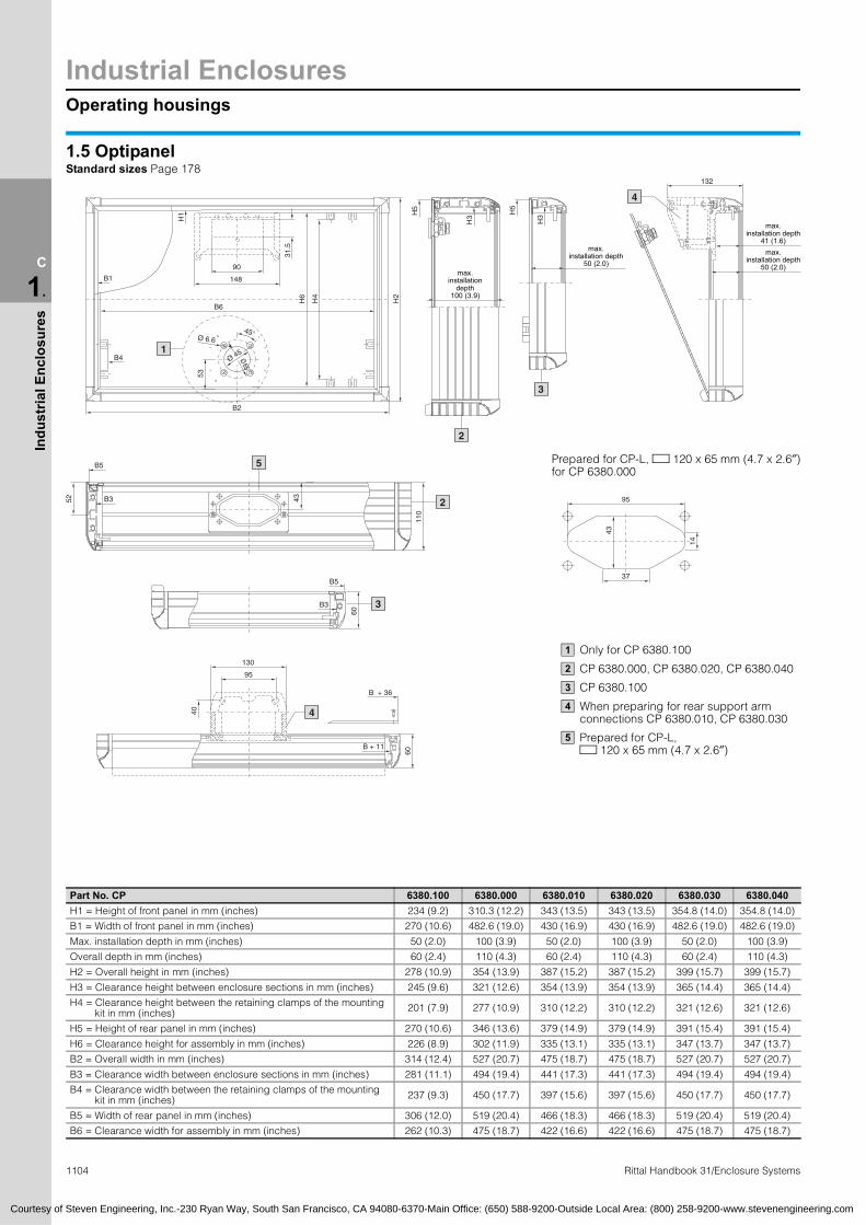
Industrial EnclosuresOperating housings
C
1.
Indu
stria
l Enc
losu
res
H6
H4
H2
B4
B1
H1
B2
B6
Ø 6.645°
Ø 45
Ø 65
53
31.5
148
90
1
H
H3
2
H
H3
3
B3 43
B5
52
110
5
2
B5
B3
60
3
37
14
43
95
130
95
40
B + 36
60
B + 11
4
Courtesy of Steven Engineering, Inc.-230 Ryan Way, South San Francisco, CA 94080-6370-Main Office: (650) 588-9200-Outside Local Area: (800) 258-9200-www.stevenengineering.com
1104 Rittal Handbook 31/Enclosure Systems
Part No. CP 6380.100 6380.000 6380.010 6380.020 6380.030 6380.040
H1 = Height of front panel in mm (inches) 234 (9.2) 310.3 (12.2) 343 (13.5) 343 (13.5) 354.8 (14.0) 354.8 (14.0)
B1 = Width of front panel in mm (inches) 270 (10.6) 482.6 (19.0) 430 (16.9) 430 (16.9) 482.6 (19.0) 482.6 (19.0)
Max. installation depth in mm (inches) 50 (2.0) 100 (3.9) 50 (2.0) 100 (3.9) 50 (2.0) 100 (3.9)
Overall depth in mm (inches) 60 (2.4) 110 (4.3) 60 (2.4) 110 (4.3) 60 (2.4) 110 (4.3)
H2 = Overall height in mm (inches) 278 (10.9) 354 (13.9) 387 (15.2) 387 (15.2) 399 (15.7) 399 (15.7)
H3 = Clearance height between enclosure sections in mm (inches) 245 (9.6) 321 (12.6) 354 (13.9) 354 (13.9) 365 (14.4) 365 (14.4)
H4 = Clearance height between the retaining clamps of the mountingkit in mm (inches) 201 (7.9) 277 (10.9) 310 (12.2) 310 (12.2) 321 (12.6) 321 (12.6)
H5 = Height of rear panel in mm (inches) 270 (10.6) 346 (13.6) 379 (14.9) 379 (14.9) 391 (15.4) 391 (15.4)
H6 = Clearance height for assembly in mm (inches) 226 (8.9) 302 (11.9) 335 (13.1) 335 (13.1) 347 (13.7) 347 (13.7)
B2 = Overall width in mm (inches) 314 (12.4) 527 (20.7) 475 (18.7) 475 (18.7) 527 (20.7) 527 (20.7)
B3 = Clearance width between enclosure sections in mm (inches) 281 (11.1) 494 (19.4) 441 (17.3) 441 (17.3) 494 (19.4) 494 (19.4)
B4 = Clearance width between the retaining clamps of the mountingkit in mm (inches) 237 (9.3) 450 (17.7) 397 (15.6) 397 (15.6) 450 (17.7) 450 (17.7)
B5 = Width of rear panel in mm (inches) 306 (12.0) 519 (20.4) 466 (18.3) 466 (18.3) 519 (20.4) 519 (20.4)
B6 = Clearance width for assembly in mm (inches) 262 (10.3) 475 (18.7) 422 (16.6) 422 (16.6) 475 (18.7) 475 (18.7)
132
4
1.5 OptipanelStandard sizes Page 178
5 5
max.installation
depth100 (3.9)
max.installation depth
50 (2.0)
max.installation depth
41 (1.6)max.
installation depth50 (2.0)
Only for CP 6380.100
CP 6380.000, CP 6380.020, CP 6380.040
CP 6380.100
When preparing for rear support arm connections CP 6380.010, CP 6380.030
Prepared for CP-L, 120 x 65 mm (4.7 x 2.6″)
1
2
3
4
5
Prepared for CP-L, 120 x 65 mm (4.7 x 2.6″)for CP 6380.000
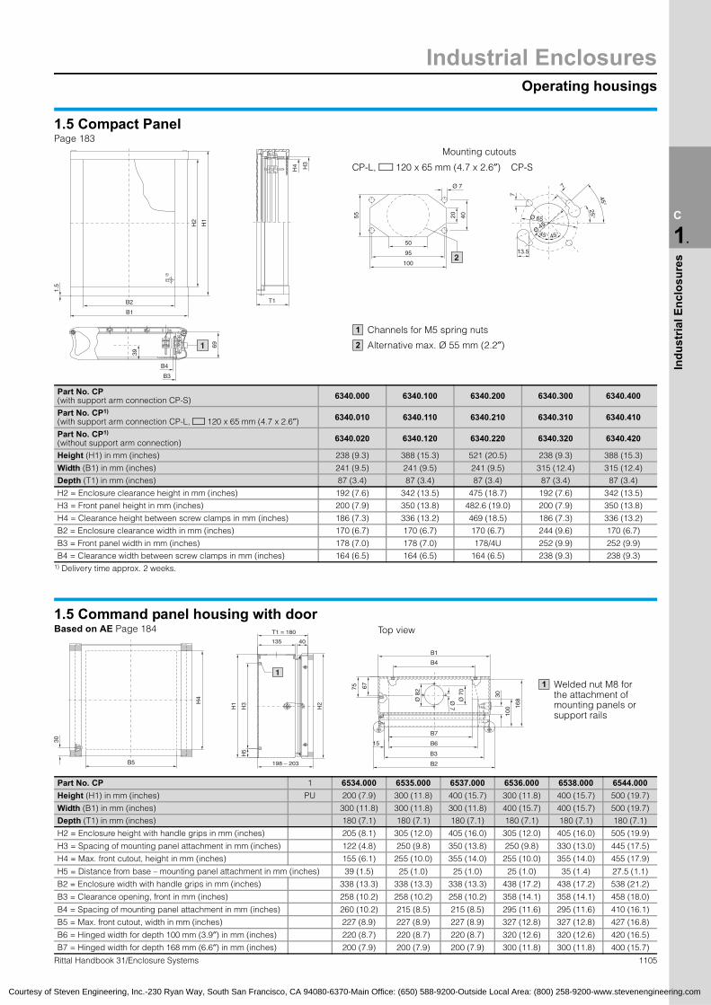
Operating housings
Industrial Enclosures
C
1.
Indu
stria
l Enc
losu
res
B1
B2
1.5
H1
H2
B4
69
39
1
50
95
100
55 4020
2
45°45°Ø 45
Ø 65
13.5
°
25°
T1
B5
H4
30
75
B4
B2
B3
30
B6
100
67
168
B7
15
Ø 7
0
Ø 7
Ø 8
2
H5
H3
H1
H2
198 – 203
1
Courtesy of Steven Engineering, Inc.-230 Ryan Way, South San Francisco, CA 94080-6370-Main Office: (650) 588-9200-Outside Local Area: (800) 258-9200-www.stevenengineering.com
1.5 Compact PanelPage 183
CP-L, 120 x 65 mm (4.7 x 2.6″) CP-SH4 H3
Mounting cutouts
7
7 45
Ø 7
Channels for M5 spring nuts
Alternative max. Ø 55 mm (2.2″)
1
2
B3
Part No. CP (with support arm connection CP-S) 6340.000 6340.100 6340.200 6340.300 6340.400
Part No. CP1)
(with support arm connection CP-L, 120 x 65 mm (4.7 x 2.6″) 6340.010 6340.110 6340.210 6340.310 6340.410
Part No. CP1)
(without support arm connection) 6340.020 6340.120 6340.220 6340.320 6340.420
Height (H1) in mm (inches) 238 (9.3) 388 (15.3) 521 (20.5) 238 (9.3) 388 (15.3)
Width (B1) in mm (inches) 241 (9.5) 241 (9.5) 241 (9.5) 315 (12.4) 315 (12.4)
Depth (T1) in mm (inches) 87 (3.4) 87 (3.4) 87 (3.4) 87 (3.4) 87 (3.4)
H2 = Enclosure clearance height in mm (inches) 192 (7.6) 342 (13.5) 475 (18.7) 192 (7.6) 342 (13.5)
H3 = Front panel height in mm (inches) 200 (7.9) 350 (13.8) 482.6 (19.0) 200 (7.9) 350 (13.8)
H4 = Clearance height between screw clamps in mm (inches) 186 (7.3) 336 (13.2) 469 (18.5) 186 (7.3) 336 (13.2)
B2 = Enclosure clearance width in mm (inches) 170 (6.7) 170 (6.7) 170 (6.7) 244 (9.6) 170 (6.7)
B3 = Front panel width in mm (inches) 178 (7.0) 178 (7.0) 178/4U 252 (9.9) 252 (9.9)
B4 = Clearance width between screw clamps in mm (inches) 164 (6.5) 164 (6.5) 164 (6.5) 238 (9.3) 238 (9.3)1) Delivery time approx. 2 weeks.
B1
1.5 Command panel housing with doorBased on AE Page 184
135 40
T1 = 180 Top view
Welded nut M8 for the attachment of mounting panels or support rails
1
1105Rittal Handbook 31/Enclosure Systems
Part No. CP 1 6534.000 6535.000 6537.000 6536.000 6538.000 6544.000
Height (H1) in mm (inches) PU 200 (7.9) 300 (11.8) 400 (15.7) 300 (11.8) 400 (15.7) 500 (19.7)
Width (B1) in mm (inches) 300 (11.8) 300 (11.8) 300 (11.8) 400 (15.7) 400 (15.7) 500 (19.7)
Depth (T1) in mm (inches) 180 (7.1) 180 (7.1) 180 (7.1) 180 (7.1) 180 (7.1) 180 (7.1)
H2 = Enclosure height with handle grips in mm (inches) 205 (8.1) 305 (12.0) 405 (16.0) 305 (12.0) 405 (16.0) 505 (19.9)
H3 = Spacing of mounting panel attachment in mm (inches) 122 (4.8) 250 (9.8) 350 (13.8) 250 (9.8) 330 (13.0) 445 (17.5)
H4 = Max. front cutout, height in mm (inches) 155 (6.1) 255 (10.0) 355 (14.0) 255 (10.0) 355 (14.0) 455 (17.9)
H5 = Distance from base – mounting panel attachment in mm (inches) 39 (1.5) 25 (1.0) 25 (1.0) 25 (1.0) 35 (1.4) 27.5 (1.1)
B2 = Enclosure width with handle grips in mm (inches) 338 (13.3) 338 (13.3) 338 (13.3) 438 (17.2) 438 (17.2) 538 (21.2)
B3 = Clearance opening, front in mm (inches) 258 (10.2) 258 (10.2) 258 (10.2) 358 (14.1) 358 (14.1) 458 (18.0)
B4 = Spacing of mounting panel attachment in mm (inches) 260 (10.2) 215 (8.5) 215 (8.5) 295 (11.6) 295 (11.6) 410 (16.1)
B5 = Max. front cutout, width in mm (inches) 227 (8.9) 227 (8.9) 227 (8.9) 327 (12.8) 327 (12.8) 427 (16.8)
B6 = Hinged width for depth 100 mm (3.9″) in mm (inches) 220 (8.7) 220 (8.7) 220 (8.7) 320 (12.6) 320 (12.6) 420 (16.5)
B7 = Hinged width for depth 168 mm (6.6″) in mm (inches) 200 (7.9) 200 (7.9) 200 (7.9) 300 (11.8) 300 (11.8) 400 (15.7)

Industrial EnclosuresOperating housings
1106 Rittal Handbook 31/Enclosure Systems
C
1.
Indu
stria
l Enc
losu
res
H3
B4
B2
1
Ø 82
Ø 7
B3
20
B1
Ø 7
0
234
(179
)
190
(135
)
T1
H1
H2
35
20
8 x 12.5
4.6
2
A
A
BB
B3
H3
B2
H2
H1
34
210
T1
= 2
49
190
15
15.5B4
15.5
H4
35 8 x 12.5
4.6
H5
1
Courtesy of Steven Engineering, Inc.-230 Ryan Way, South San Francisco, CA 94080-6370-Main Office: (650) 588-9200-Outside Local Area: (800) 258-9200-www.stevenengineering.com
1.5 Operating housingsBased on AE Page 185
120 Top view
Only for CP 6532.200 and CP 6533.200
For CP 6532.2002 cams
1
2
Note:Dimensions in brackets for CP 6540.200.
Part No. CP 1 6540.2001) 6531.200 6530.200 6532.200 6533.200
Height (H1) in mm (inches) PU 200 (7.9) 300 (11.8) 380 (15.0) 500 (19.7) 380 (15.0)
Width (B1) in mm (inches) 300 (11.8) 380 (15.0) 380 (15.0) 500 (19.7) 600 (23.6)
Depth (T1) in mm (inches) 155 (6.1) 210 (8.3) 210 (8.3) 210 (8.3) 210 (8.3)
H2 = Hole distance of side-mounting angles in mm (inches) 75 (3.0) 175 (6.9) 275 (10.8) 375 (14.8) 275 (10.8)
H3 = Cutout, in enclosure in mm (inches) 150 (5.9) 250 (9.8) 330 (13.0) 450 (17.7) 330 (13.0)
B2 = Enclosure width with handle grips in mm (inches) 340 (13.4) 420 (16.5) 420 (16.5) 540 (21.3) 640 (25.2)
B3 = Clearance opening, front in mm (inches) 260 (10.2) 340 (13.4) 340 (13.4) 460 (18.1) 560 (22.0)
B4 = Cutout, in enclosure in mm (inches) 250 (9.8) 330 (13.0) 330 (13.0) 450 (17.7) 550 (21.7)1) Support arm connection and door hinge at the bottom.
1.5 Operating housingBased on AE with display panel front Page 186
B1Section A – A Section B - B
120
For CP 6442.500only 1 cam in the center.
1
Part No. CP 1 6442.500 6462.500 6552.500 6662.500
Height (H1) in mm (inches) PU 380 (15.0) 600 (23.6) 500 (19.7) 600 (23.6)
Width (B1) in mm (inches) 380 (15.0) 380 (15.0) 500 (19.7) 600 (23.6)
Depth (T1) in mm (inches) 249 (9.8) 249 (9.8) 249 (9.8) 249 (9.8)
H2 = Height of display panel front in mm (inches) 377 (14.8) 597 (23.5) 497 (19.6) 597 (23.5)
H3 = Clearance opening, front in mm (inches) 307 (12.1) 527 (20.7) 427 (16.8) 527 (20.7)
H4 = Height of front panel in mm (inches) 321 (12.6) 541 (21.3) 441 (17.4) 541 (21.3)
H5 = Hole distance of side-mounting angles in mm (inches) 250 (9.8) 450 (17.7) 350 (13.8) 450 (17.7)
B2 = Width of display panel front in mm (inches) 379 (14.9) 379 (14.9) 499 (19.6) 599 (23.6)
B3 = Clearance opening, front in mm (inches) 309 (12.2) 309 (12.2) 429 (16.9) 529 (20.8)
B4 = Width of front panel in mm (inches) 323 (12.7) 323 (12.7) 443 (17.4) 543 (21.4)

Stand systems
Industrial Enclosures
1107Rittal Handbook 31/Enclosure Systems
C
1.
Indu
stria
l Enc
losu
res
600
957
273
85
521
85
162 BB
A A
3
M12
55°
50
130
136
18
660
13
1093
2
4
600
456
700
140
Ø 7
0
312
660
M12
18
13
5
76
1.5 PedestalPage 232
For Command Panel For IW worktops
Ø 7.4
40
69
34
R 17R 7.5
M5
48
28 44
8058
R43
2
44.5
1
140
700
456
600
70
130
A – A
B – B
Cover forcable entry
A – A
Max. PG 48/M50
Cross-sectioncable entry
Cutoutonly for CP 6141.100
Cable conduit adaptor only for CP 6141.100
1
2
3
4
Prepared forWorktopIW 6902.310/.330
Prepared for trim panel CP 6144.100 or foot rest CP 6145.100
Prepared for twin castors CP 6148.000 or base-mounting CP 6147.000
5
6
7
AA
380
350
90
600
521
946
2285
1.5 Pedestal mobilePage 235
C 30/15 x 100 lg
20
80
60
100
800
800
205
50
8560
0
80
550
160
75
R95
R110View A
View A
1.5 Pillar, smallPage 235
54
64
500
M8
35
50
160
450
80
450
500
Ø 12.5
M432
130
112
12
36
1150
A
View A
Courtesy of Steven Engineering, Inc.-230 Ryan Way, South San Francisco, CA 94080-6370-Main Office: (650) 588-9200-Outside Local Area: (800) 258-9200-www.stevenengineering.com
A
CP 6136.500
ACP 6136.000

Industrial EnclosuresStand systems
1108 Rittal Handbook 31/Enclosure Systems
C
1.
Indu
stria
l Enc
losu
res
M12
660
18
13
1 2
138
456
Ø 11
140
88700
M12
480
200
490
440
600
1
2
3
4
1.5 Cross member/base platePages 233/234
Cross member with cast feet Pedestal base plate, large
521
600
85
B A
100
65
5915 6 18.5
50 18.5
51
View A View BPrepared fortrim panel CP 6144.100 orfoot rest CP 6145.100
Prepared fortwin castors CP 6148.000or base-mounting CP 6147.000
1
2
510 for floor anchoringwith KL 1580.000, KL 1590.000
400 for floor anchoringwith KL 1580.000, KL 1590.000
Cutout for CP 6137.035
Cutout for CP 6137.535
1
3
4
1
2
3 4
B
C B
H
110
CP 6522.0X0
126
CP 6520.0X0
192
160
D
100
100
15
A
62
17
CP 6521.0X0
69
101
CP 6110.000 CP 6160.000
89.5
172
CP 6170.000
2
4
3
CP 6501.110 CP 6501.160
CP 6501.110
70
57
CP 6501.150
102
1
Courtesy of Steven Engineering, Inc.-230 Ryan Way, South San Francisco, CA 94080-6370-Main Office: (650) 588-9200-Outside Local Area: (800) 258-9200-www.stevenengineering.com
1.5 PillarPage 236
Part No. CP A B C D
6214.XX0 140 200 280 120
6220.XX0 200 300 400 180
Support arm connection according to the design code number
Cutout for cable entry according to the design code number
Cutout in base plate
Metal gland plate,see page 969.
1
2
3
4

Industrial workstations
Industrial Enclosures
1109Rittal Handbook 31/Enclosure Systems
C
1.
Indu
stria
l Enc
losu
res
Courtesy of Steven Engineering, Inc.-230 Ryan Way, South San Francisco, CA 94080-6370-Main Office: (650) 588-9200-Outside Local Area: (800) 258-9200-www.stevenengineering.com
1.5 EnclosuresPage 245
Part No. IW
H mm(inches) 900 (35.4) 900 (35.4) 900 (35.4) 900 (35.4) 900 (35.4) 900 (35.4) 1000
(39.4)1000 (39.4)
1000 (39.4)
W/D mm(inches)600/600(23.6/23.6)
6900.000 6900.100 6900.200 6900.400 6900.410 6900.600 6901.000 6901.100 6901.200
Configu-ration Version Material Color
RAL RAL 7035 (light gray); RAL 7015 (slate gray); RAL 9006 (aluminum white)
Enclo-sures
Frame construction with side panels,screw-fastened from the inside
Sheet steel, 1.5 mm (16 ga)
7035 textured
� � � � � � � � � Base with gland plate for cable entry
Leveling feet to compensate for floor irregularities
Trim panel, top
To finish off the enclosure at the top
Plastic to UL 94-V0
7035/7015 � � �
Keyboard drawer
Drawer housing
Sheet steel, 1.5 mm (16 ga) 7035
� �
Extension piece with cable support, hinged, plus pull-out mouse-pad and keyboardcradle
Trim panel with recessed handle, folded as handrest, with lock no. 3524 E
Plastic toUL 94-V0
7035/7015/9006
Drawer section
Drawer tray, fitted with drawer trim panel and telescopic slides
Sheet steel, 1.5 mm (16 ga) 7035 �
Extension piece with cable support, hinged, plus pull-out mouse-pad
Sheet steel, 1.5 mm (16 ga) 7035 �
Drawer trim panel with handle recess,with lock no. 3524 E
Plastic toUL 94-V0
7035/7015/9006
� �
Designer door
Vertical bars with lock-ing rod and double-bit insert, hinged on right-hand side
Aluminiumsection 7035
� � � � � � �
Door or installation plate, folded
Sheet steel, 1.5 mm (16 ga) 7015
Viewing door
Vertical decorative trim panels
Plastic toUL 94-V0 7035
� Glass with screen-printed mask
Safety glass 4.0 mm (0.2″) 7015
Drawer front
Drawer tray, slotted for cross member retainers,1x with low trim piece, 2x with high trim piece, each with handle recess,telescopic slides
Sheet steel, 1.5 mm (16 ga)
7035/7015/9006
�
Worktop Solid
Chipboard, plastic-laminated on both sides, with edge strip
similar to 7035 Edge strip: similar to 7015
�
Roof Edged, screw-fastened from the inside
Sheet steel, 1.5 mm (16 ga)
7035 textured �
Rear wallScrew-fastened from the inside Sheet steel, 1.5
mm (16 ga)7035 textured
� �
Screw-fastened from the outside �
Rear doorWith locking rod and double-bit,insert, right hinge
Sheet steel, 1.5 mm (16 ga)
7035 textured � � � � � �

Industrial EnclosuresIndustrial workstations
1110 Rittal Handbook 31/Enclosure Systems
C
1.
Indu
stria
l Enc
losu
res
900
(100
0)
604
512
362
4
3
812
(912
)
636
869
(969
)
512
1
2
512
362
604
1043
145
75
(101
8)
608
512
636
526
912
118
669
Dimensions in brackets for IW 6901.200. Dimensions in brackets for IW 6901.000.
512
900
7514
532
032
0
604
812
86.5
60
636
512
309
(240) (533)
465
237
889
512
362
604
902
145
512
812
518
275
100
83
655
36
11
1
Shelves with punchings for cross members
1
458
597
460
385
600
510
402 (502)
536 (636)
Dimensions in brackets only forIW 6902.XXX.
Monitor housingIW 6902.500IW 6902.510
Dimensions in brackets for IW 6900.410.
Courtesy of Steven Engineering, Inc.-230 Ryan Way, South San Francisco, CA 94080-6370-Main Office: (650) 588-9200-Outside Local Area: (800) 258-9200-www.stevenengineering.com
1.5 EnclosuresPages 245/246/250
Enclosure Enclosure
IW 6901.100IW 6901.200IW 6900.000IW 6901.000IW 6900.100IW 6900.200
Rear wall for IW 6900.100 and IW 6900.200
Rear wall for IW 6900.000 and IW 6901.000
Design door for IW 6900.000, IW 6901.000 and IW 6900.100
Viewing door for IW 6900.200
1
2
3
4
EnclosureIW 6900.400IW 6900.410
EnclosureIW 6900.600

Industrial workstations
Industrial Enclosures
1111Rittal Handbook 31/Enclosure Systems
C
1.
Indu
stria
l Enc
losu
res
1.5 WorktopsPages 247 – 249
608
512
403
480
480
512
614
642
50
300
50
75
13
t = 1.5155155
1000
162.
5
317.
5
895 76
1
162.
5
60
R10
00
60
1
0
3
t = 38
618
645
400
t = 38
1200
(155)155
1009 95
0
155
162.
5
(162
.5)
R10
00
60
589
60 t = 38
1
0
3
2
317.
5
Without mounting cutout for IW 6902.100
Mounting cutout, left side, for enclosure attachment,only for CP 6902.120
Mounting cutout, right side, for enclosure attachment, only for CP 6902.130
Mounting cutout prepared for turntable,only for CP 6902.110
0
1
2
3
Without mounting cutoutfor IW 6902.000
Mounting cutout, left side,for enclosure attachment, only for CP 6902.020
Mounting cutout, right side, for enclosure attachment, only for CP 6902.030
Mounting cutout prepared for turntable, only for CP 6902.010
0
1
2
3
WorktopIW 6902.310
WorktopIW 6902.320
950
260
593.5
490
600
658
t = 38
950
260
590
490
600
t = 38
2000
685
R50
t = 38
WorktopIW 6902.200
2000
90076
6685 t = 38
12
WorktopIW 6902.210
IW 6902.210
IW 6902.220 (arranged as mirror)
1
2
Courtesy of Steven Engineering, Inc.-230 Ryan Way, South San Francisco, CA 94080-6370-Main Office: (650) 588-9200-Outside Local Area: (800) 258-9200-www.stevenengineering.com
RoofIW 6902.400
Worktop, without handle,IW 6902.100IW 6902.110IW 6902.120IW 6902.130
2
WorktopIW 6902.300
610
Worktop, with handle,IW 6902.000IW 6902.010IW 6902.020IW 6902.030

Industrial EnclosuresPC enclosure systems
1112 Rittal Handbook 31/Enclosure Systems
C
1.
Indu
stria
l Enc
losu
res
366 190i.L. 512
202
122
833
70
924
530
1 2
i.L. 512
841
150
1605
362
455
500
i.L. 512
636
122
833
924
70
530
460
384
150
362
589
841
6445
8
i.L. 512
1605
366 190
558
122
924
70
636 (836)
i.L. 512 (712)
833
530
1 2 386
454
1605
362
841
439
362
6430
8
150
150
112
mm (inches) Part No. PCDepth 636 (25.0) 8366.000 8366.300 8366.400
Depth 836 (32.9) 8368.000 – –
Configuration Design Material Color RAL
EnclosureFrame construction with side panels and roof secured from the inside Sheet steel 1.5 mm (16 ga) 7035 (light gray)
textured � � � Gland plates, three-part Sheet steel 1.5 mm (16 ga) Zinc-plated
Rear door With locking rod and double-bit insert, hinged on the right-hand side Sheet steel 2.0 mm (14 ga) 7035 (light gray)
textured � � �
Viewing door, top
With support frame latched from the inside1), right hinge Sheet steel 1.5 mm (16 ga) 7015 (slate gray)
� � Vertical decorative trim panels Plastic to UL 94-V0 7035 (light gray)
Glass with screen-printed mask Safety glass 4.0 mm (0.2″) 7015 (slate gray)
Mounting compartment,large, top
Vertical bars, latched from the inside1), right hinge Aluminium section 7035 (light gray)
� Installation plate Sheet steel 1.5 mm (16 ga) 7015 (slate gray)
Trim strip top/bottom Plastic to UL 94-V0 7035 (light gray)
Component shelffor monitor
Slotted, permanently installed Sheet steel 1.5 mm (16 ga) 7015 (slate gray) � �
Drawer for keyboard
Enclosure Sheet steel 1.5 mm (16 ga) 7035 (light gray)
� � �
Keyboard extension piece with cable support, hingedmousepad extension piece and keyboard cradle Sheet steel 1.5 mm (16 ga) 7035 (light gray)
Trim panel with recessed handle, folded as handrest, with lock no. 3524 E Plastic to UL 94-V0
7035 (light gray)/7015 (slate gray)/9006 (aluminum white)
Mounting compartment, small
Right hinge, screw-fastened from the inside on left,folded installation plate Sheet steel 1.5 mm (16 ga) 7015 (slate gray)
� Decorative side trim panels Plastic to UL 94-V0 7035 (light gray)
Bottom doorVertical bars with locking rod and double-bit insert, hinged on right-hand side Aluminium section 7035 (light gray)
� � � Door or installation plate folded Sheet steel 1.5 mm (16 ga) 7015 (slate gray)
1) With unlatching for viewing door, top.
Max. 505 mm (19.9″), adjustable on a 25 mm (1.0″) hole pattern
Max. 549 mm (21.6″), adjustable on a 25 mm (1.0″) hole pattern
1
2
i.L. = Clearance width
Courtesy of Steven Engineering, Inc.-230 Ryan Way, South San Francisco, CA 94080-6370-Main Office: (650) 588-9200-Outside Local Area: (800) 258-9200-www.stevenengineering.com
1.5 Based on TS8With keyboard drawer Page 257
With drawerPC 8366.000, PC 8368.000
605 624 (824)
624With mounting compartment, small and drawerPC 8366.300
i.L. 512
605
636
Max. 355 mm (14.0″), adjustable on a 25 mm (1.0″) hole pattern
Max. 397 mm (15.6″), adjustable on a 25 mm (1.0″) hole pattern
1
2
605 624 366 190
With mounting compartment, large and drawerPC 8366.400

PC enclosure systems
Industrial Enclosures
1113Rittal Handbook 31/Enclosure Systems
C
1.
Indu
stria
l Enc
losu
res386
454
1605
362
439
300
841
6430
8
i.L. 512
605
i.L. 512 (712)
287624 (824)
157
397 (597)
380
422
636 (836)
1005
803
330
379
225
300
384
460
1605
362
i.L. 512
605
841
150
6445
8
589
636
1512
175
908
i.L. 512
(270)
11°
1 23
1.5 Based on TS8With folding keyboard or desk section Page 258
mm (inches) Part No. PCDepth 636 (25.0) 8366.100 8366.200
Depth 836 (32.9) 8368.100 –
Configuration Design Material Color RAL
EnclosureFrame construction with side panels and roof secured from the inside Sheet steel 1.5 mm (16 ga) 7035 (light gray)
textured � � Gland plates, three-part Sheet steel 1.5 mm (16 ga) Zinc-plated
Rear door With locking rod and double-bit insert, right hinge Sheet steel 2.0 mm (14 ga) 7035 (light gray)textured � �
Viewing door, top
With support frame latched from the inside1), right hinge Sheet steel 1.5 mm (16 ga) 7015 (slate gray)
� � Vertical decorative trim panels Plastic to UL 94-V0 7035 (light gray)
Glass with screen-printed mask Safety glass 4.0 mm (0.2″) 7015 (slate gray)
Component shelf for monitor Slotted, permanently installed Sheet steel 1.5 mm (16 ga) 7015 (slate gray) � �
Fold-out trayfor keyboard
Enclosure with mouse holder and cutout in the rear panel, width 482.6 mm (19″) x height 4U, for rear attachment Sheet steel 1.5 mm (16 ga) 7035 (light gray)
� Trim panel hinged at the bottom, with 2 retaining cords, with lock no. 3524 E Plastic to UL 94-V0
7035 (light gray)/7015 (slate gray)/9006 (aluminum white)
Keyboard support with mousepad extension piece and 2 nylon bands for keyboard Sheet steel 1.5 mm (16 ga) 7035 (light gray)
Desk section
Enclosure with removable cover top and bottom Sheet steel 1.5 mm (16 ga)/2.0 mm (14 ga) 7035 (light gray)
� Trim strip, top and handle strip Plastic to UL 94-V0
7035 (light gray)/7015 (slate gray)/9006 (aluminum white)
Bottom doorVertical bars with locking rod and double-bit insert, right hinge Aluminium section 7035 (light gray)
� � Door or installation plate folded Sheet steel 1.5 mm (16 ga) 7015 (slate gray)
Max. 505 mm (19.9″), adjustable on a 25 mm (1.0″) hole pattern
Max. 549 mm (21.6″), adjustable on a 25 mm (1.0″) hole pattern
Max. installation area 540 x 175 mm (21.3 x 6.9″)
1
2
3
i.L. = Clearance width
Courtesy of Steven Engineering, Inc.-230 Ryan Way, South San Francisco, CA 94080-6370-Main Office: (650) 588-9200-Outside Local Area: (800) 258-9200-www.stevenengineering.com
With fold-out trayPC 8366.100, PC 8368.100
624
894
With desk sectionPC 8366.200

Industrial EnclosuresPC enclosure systems
C
1.
Indu
stria
l Enc
losu
res
1604
863
492
591
125
i.L. 512
54
500
483
1
854
939
620
i.L. 502
558
100
57
530
939
620 (820)
i.L. 502 (702)
854
558
100
57
530
1 2
939
854
558
100
i.L. 502
57
530
1 2
1.5 Based on ESWith keyboard drawer Page 259
Max. 355 mm (14.0″), adjustableon a 25 mm (1.0″) hole pattern
Max. 397 mm (15.7″), adjustableon a 25 mm (1.0″) hole pattern
1
2
1604
410
i.L. 512
591
863
125
492
8242
5
410
46520
M8 x 20
1604
8227
510
0
492
i.L. 512
150
863
125
4044
1
82.6 (19˝)
50
Max. 505 mm (19.9″)adjustableon a 25 mm (1.0″) hole pattern
Max. 547 mm (21.5″)adjustableon a 25 mm 1.0″) hole pattern
1
2
i.L. = Clearance w
Courtesy of Steven Engineering, Inc.-230 Ryan Way, South San Francisco, CA 94080-6370-Main Office: (650) 588-9200-Outside Local Area: (800) 258-9200-www.stevenengineering.com
599 647 205318
With mounting compartment, large and drawerPC 4603.603
External surface available for population
1
647 (847) 205318599
With drawerPC 4603.703, PC 4609.703
4
4
T max. 200
idth
647 318 205599
(
With mounting compartment, small and drawer PC 4603.913
1114 Rittal Handbook 31/Enclosure Systems
620
Configura-tion Design Material Color RAL PC
4603.603 PC 4603.703 PC 4609.703
PC 4603.913
EnclosureSolid, open at bottom Sheet steel 1.5 mm (16 ga) 7035 (light gray)
textured � � � Gland plates, three-part Sheet steel 1.5 mm (16 ga) Zinc-plated
Rear door With locking rod and double-bit insert, right hinge Sheet steel 2.0 mm (14 ga) 7035 (light gray) textured � � �
Mounting compart-ment,large, top
Vertical bars, latched from the inside1), hinged on right-hand side Aluminium section 5018
(turquoise blue)� Folded installation plate Sheet steel 1.5 mm (16 ga) 7035 (light gray)
Trim strip top/bottom Plastic to UL 94-V0 7035 (light gray)
Viewing doortop
Vertical bars, latched from the inside2), right hinge Aluminium section 5018(turquoise blue)
� � Trim strip top/bottom Plastic to UL 94-V0 7035 (light gray)
Glass with screen-printed mask Safety glass 4.0 mm (0.2″) 7015 (slate gray)
Component shelffor monitor
Slotted, permanently installed Sheet steel 1.5 mm (16 ga) 7035 (light gray) � �
Drawer for keyboard
Enclosure Sheet steel 1.5 mm (16 ga) 7035 (light gray)
� � �
Keyboard extension piece with 1 pair of telescopic slides Sheet steel 1.5 mm (16 ga) 7035 (light gray)
Trim panel with recessed handle, folded as handrest, with lock no. 3524 E
Plasticto UL 94-V0 7035 (light gray)
Decorative side trim panels Aluminium section 5018 (turquoise blue)
2 spacers for slimline keyboards Cellular rubber1) With unlatching for top viewing door
Mounting compart-ment,small
Right hinge, screw-fastened from the inside on left,folded installation plate Sheet steel 1.5 mm (16 ga) 7035 (light gray)
� Trim strip at the bottom Plastic to UL 94-V0 7035 (light gray)
Vertical bars Aluminium section 5018 (turquoise blue)
Bottom door
Vertical bars with locking rod, Ergoform-S handle and double-bit insert, right hinge Aluminium section 5018
(turquoise blue) � � � Door or installation plate folded Sheet steel 1.5 mm (16 ga) 7035 (light gray)2) With unlatching for top viewing door with desk section

PC enclosure systems
Industrial Enclosures
1115Rittal Handbook 31/Enclosure Systems
C
1.
Indu
stria
l Enc
losu
res
410
492
1604
8227
5
i.L. 512
863
441
275
1001
385 (585)
620 (820)
i.L. 502 (702)40
8
450
275
829
155
1604
410
i.L. 512
591
863
125
492
8242
5
486
208
11°
620
45
i.L. 502
i.L. 1
512
200 65
912
1 2
1.5 Based on ESWith folding keyboard or desk section Page 260
i.L. = Clearance width
Courtesy of Steven Engineering, Inc.-230 Ryan Way, South San Francisco, CA 94080-6370-Main Office: (650) 588-9200-Outside Local Area: (800) 258-9200-www.stevenengineering.com
599 231647 (847)
With fold-out trayPC 4603.920, PC 4609.920
599 647
With desk sectionPC 4603.704
Max.505 mm (19.9″),adjustableon a 25 mm (1.0″) hole pattern
Max. 547 mm (21.5″),adjustableon a 25 mm (1.0″) hole pattern
1
2
Configuration Design Material Color RAL PC 4603.920PC 4609.920
PC4603.704
EnclosureSolid, open at bottom Sheet steel 1.5 mm (16 ga) 7035 (light gray)
textured � � Gland plates, three-part Sheet steel 1.5 mm (16 ga) Zinc-plated
Rear door With locking rod and double-bit insert, right hinge Sheet steel 2.0 mm (14 ga) 7035 (light gray)textured � �
Viewing door, top
Curved outwards, vertical bars,latched on the inside1), right hinge Aluminium section 5018 (turquoise blue)
� � Trim strip top/bottom Plastic to UL 94-V0 7035 (light gray)
Glass with screen-printed mask Safety glass 4.0 mm (0.2″) 7015 (slate gray)
Component shelffor monitor Slotted, permanently installed Sheet steel 1.5 mm (16 ga) 7035 (light gray) � �
Fold-out trayfor keyboard
Enclosure with cutout in rear panel,width 19″ x height 4U, with screw-fastened lid Sheet steel 1.5 mm (16 ga) 7035 (light gray)
� Trim panel hinged at the bottom with2 retaining shears, with lock no. 3524 E Plastic to UL 94-V0 7035 (light gray)
Decorative side trim panels Aluminium section 5018 (turquoise blue)
Keyboard support,with 2 nylon loops for keyboard Sheet steel 7035 (light gray)
1) With unlatching for top viewing door
Desk section
Enclosure with removable lidtop and bottom.
Sheet steel 1.5 mm (16 ga)/2.0 mm (14 ga)
7035 (light gray)
� Trim strip, top and handle Plastic to UL 94-V0 7035 (light gray)
Decorative side trim panels Aluminium section 5018 (turquoise blue)
Bottom door
Vertical bars with locking rod, Ergoform-S handle and double-bit insert, right hinge Aluminium section 5018 (turquoise blue)
� � Door or installation plate folded Sheet steel 1.5 mm (16 ga) 7035 (light gray) 1) With unlatching for top viewing door with desk section

Industrial EnclosuresConsole systems AP
1116 Rittal Handbook 31/Enclosure Systems
C
1.
Indu
stria
l Enc
losu
res
800
50
724
7971.5
300
630
33.5 50
58
700
1100/1500
525/725
50
525/725
1124/1524
1200/1600
630
300
5050
33
33.5
101.
5
10.2
702/1102/1502
16.5
40.5
1919
10.2
816.5
36
24
20.5
532
3
1250
700
50
50
40
102524
Ø 10
120
100
16
597 (797) 595 (795)
5
5
1.5
50
1100 (1500)
40
10
25
120
100
24
Ø 1016
1.5 597 (797)595 (795)
50
1.5 PedestalsPage 265
H x W 670 x 1200/1600 mm (26.4 x 47.2/63.0″)AP 2620.500, AP 2630.500, AP 2640.500, AP 2650.500
D 400 mm (15.7″)Without rear door AP 2600.500, AP 2620.500, AP 2630.500
D 500 mm (19.7″)AP 2640.500, AP 2650.500
D 400 mm (15.7″)AP 2600.500, AP 2620.500,AP 2630.500
Max. 407 mm (16.0″)
1
D 500 mm (19.7″)AP 2610.500, AP 2640.500,AP 2650.500
715/1115/1515
600
10 12.5
575
12.5
12.5
20909020
1
Mounting panel for D 400 mm (15.7″)
Does not apply to AP 2600.500
1
H x W 670 x 800 mm (26.4 x 31.5″)AP 2600.500, AP 2610.500
370
575
47.5
670
600
373
i.L. 27050
400
557
70
30
24
i.L. 34050
24
30
500
472
120
532
557
70
670
440
30
24
1
Mounting panel for D 500 mm (19.7″)
D 500 mm (19.7″)AP 2610.500
i.L. = Clearance width
Courtesy of Steven Engineering, Inc.-230 Ryan Way, South San Francisco, CA 94080-6370-Main Office: (650) 588-9200-Outside Local Area: (800) 258-9200-www.stevenengineering.com

Console systems AP
Industrial Enclosures
1117Rittal Handbook 31/Enclosure Systems
C
1.
Indu
stria
l Enc
losu
res
3232
365
50
3838
039
17
148.5148.5
13.4
25
797/1197/1597
6.5
1
2
320
420
i.L. 742/1142/1542
10.5
38
120
800/1200/1600
120
640/1040/1440
700/1100/1500
660/1060/1460
1
210
.5
420
38
320
420
i.L. 742/1142/1542
800/1200/1600
120
820100
950
470
37050
200
27050
788.5
27050
370
27050
850
820
758.5
19.5
200
393
460
55.5
12.5
12°
24�
46
125
41
X
1.5 Desk unitsPage 264H x D 200 x 850 mm (7.9 x 33.5″)AP 2611.500, AP 2641.500,AP 2651.500
View in X direction
Side viewH x D 200 x 950 mm (7.9 x 37.4″)AP 2613.500, AP 2643.500,AP 2653.500
Does not apply to AP 2611.500
Does not apply to AP 2611.500, AP 2641.500
1
2
Does not apply to AP 2611.500,AP 2613.500,AP 2641.500,AP 2643.500
Does not apply to AP 2611.500,AP 2613.500
1
2
i.L. = Clearance width
422/
622
304/
504
68
32
733/1133/1533
32
797/1197/1597
12
797/1197/1597
148.5
99.5
732/1132/1532
148.5
==
348/
548
423.
5/62
3.5
99.5
12
10
12.5
350
715/1115/1515
325
2090
12.5
9020
12.5
t = 3
1
T2
T1
T3
11°
X
407
353.
530
0
55.5
Y
325
370
52.5 27050
350
26
430
286.5
317.5
11°
24
440
470
340
50
30
T2
T1
T3
X
6.5
42
430
26
300
356.5
387.5
359 40
7
353.
530
0
Y
55.5 55
.5
550
500 60
4
465
630
559
84.542
7°
XZ
496455
50
546
24
440
30 340
500
146
6.5
387.5
356.5
26
106
10052
Y
742/1142/1542
797/1197/1597
800/1200/1600
11.5
9
9
9
11.5
60
4411
11.5
11.5
60°
727/1127/1527
6
2.5
23
348/
548
23
19
1.5 ConsolesPage 264H x D 430 x 400 mm (16.9 x 15.7″)AP 2612.500, AP 2642.500, AP 2652.500
H x D 430 x 500 mm (16.9 x 19.7″)AP 2614.500, AP 2644.500, AP 2654.500
Mounting panel for D 400 mm (15.7″)
View in Y direction View in X direction View in Z direction
Dimensions in mm (inches)
Depth 400 (15.7)
Depth500 (19.7)
T1 = vertically hinged 3U 300 (11.8)
T2 = vertically hinged 6U 195 (7.7)
T3 = vertically hinged, max. 110 (4.3)
T1 = static, max. 300 (11.8) 400 (15.7)
Only for AP 2649.500
Only for AP 2648.500/ AP 2649.500
1
2
H x D 630 x 500 mm (24.8 x 19.7″)with deep rear door AP 2647.500, AP 2648.500, AP 2649.500
Only for AP 2649.500, AP 2652.500, AP 2654.500,AP 2664.500
Does not apply to AP 2612.500, AP 2614.500, AP 2647.500, AP 2662.500
1
2
Courtesy of Steven Engineering, Inc.-230 Ryan Way, South San Francisco, CA 94080-6370-Main Office: (650) 588-9200-Outside Local Area: (800) 258-9200-www.stevenengineering.com
23
11.5
Does not apply to AP 2612.5001
60
Mounting panel for D 500 mm (19.7″)

Industrial EnclosuresConsoles AP
1118 Rittal Handbook 31/Enclosure Systems
C
1.
Indu
stria
l Enc
losu
res
B6
B5
B4
B1
50
1.5 1.5
47
B7
B3
B2
1
B2
52.5
498
1
420
8
61
20
6.5
52.5
31 31
25 2
12.5
12.5
92.5
4040
92.5
G1
11
27.5
F1
F2
11
78.5 78.5
11
51
B4
B7
B550
1.5 1.5
72
B3
B2
B1
630
790
557
70 3360
675
140
960
47 (
87)
(127
)
400
270
370
50
358 – 368
480
447
498
20°
X
1.5 One-piece consoles APSheet steel Page 266
Stainless steel Page 282
Part No. AP, sheet steel 2666.500 2668.500 2670.500 2672.500
Part No. AP, stainless steel 2683.600 2684.600 2685.600 2686.600
Height in mm (inches) 960 (37.8) 960 (37.8) 960 (37.8) 960 (37.8)
Width (B1) in mm (inches) 600 (23.6) 800 (31.5) 1000 (39.4) 1200 (47.2)
Depth in mm (inches) 400/480 (15.7/18.9) 400/480 (15.7/18.9) 400/480 (15.7/18.9) 400/480 (15.7/18.9)
B2 = Width in mm (inches) 597 (23.5) 797 (31.4) 997 (39.3) 1197 (47.1)
B3 = Clearance width in mm (inches) 544 (21.4) 744 (29.3) 944 (37.2) 1144 (45.0)
B4 = Clearance width, front in mm (inches) 524 (20.6) 724 (28.5) 924 (36.4) 1124 (44.3)
B5 = Clearance width, bottom in mm (inches) 500 (19.7) 700 (27.6) 900 (35.4) 1100 (43.3)
B6 = Wide adjacent door in mm (inches) – – 495 (19.5) 595 (23.4)
B7 = Wide lockable door in mm (inches) 597 (23.5) 797 (31.4) 497 (19.6) 597 (23.5)
B8 = Punched length in mm (inches) 500 (19.7) 700 (27.6) 900 (35.4) 1100 (43.3)
F1 = Mounting panel width in mm (inches) 530 (20.9) 730 (28.7) 930 (36.6) 1130 (44.5)
F2 = Distance between mounting holes in mm (inches) 475 (18.7) 675 (26.6) 875 (34.5) 1075 (42.3)
G1 = Mounting panel height in mm (inches) 780 (30.7) 780 (30.7) 780 (30.7) 780 (30.7)
37
458
33.5
498
6037
5
B8
B2
M6 x12
23.5
25
83 3
Hinge does not apply to AP 2670.500, 2685.600
Hinge does not apply to AP 2666.500, 2668.500
1
2
Hinge does not apply to AP 2683.600, 2684.600
3
i.L. 515
i.L. 512
i.L. 512
592
44036542.5
11°
502
417.5
173.
563
525
.5
44.3
2860
4
i.L. 1
212
1273
.5
1300
1i.L. 512
i.L. 512
i.L. 515
592
11°
44036542.5
502
417.5
763
835
25.5
44.3
805
i.L. 1
212
1273
.5
1300
1
23
1196
2323
48 7324.5
42
17
1.5 Universal consoles APSheet steel Page 267
Adjustable from 200 mm (7.9″) to 400 mm (15.7″) on a 25 mm (1.0″) holepattern.
1
i.L. = Clearance width
Courtesy of Steven Engineering, Inc.-230 Ryan Way, South San Francisco, CA 94080-6370-Main Office: (650) 588-9200-Outside Local Area: (800) 258-9200-www.stevenengineering.com
B86.5 16.5
Sheet steel – view in X direction
73.5Stainless steel – view in X direction
600
With short front door AP 2694.500
600
With tall front door AP 2695.500
499
Mounting panel

Stainless steel
Industrial Enclosures
1119Rittal Handbook 31/Enclosure Systems
C
1.
Indu
stria
l Enc
losu
res
B4
B3
i.L. = B2
93.6
B5
M5
Ø 4.6
29
B1
H1
29
37.5
12.5 12
.515.5
15
120
20
H4 H2
H3
15
80
15.5
H4
H2
H3
B3
i.L. = B2
B4
53.6
20
47.5
12.5
12.5
103 79
.51
M6 x 12
63
39.5
20
1
1.6 Terminal boxes KL/Ex enclosures KEL with screw-fastened lidPages 270/287
Part No. KL 1521.010 1522.010 1523.010 1524.010 1525.010 1526.010
Part No. KEL 9301.000 9302.000 9303.000 9304.000 9305.000 9306.000
Height (H1) in mm (inches) 150 (5.9) 150 (5.9) 200 (7.9) 200 (7.9) 200 (7.9) 300 (11.8)
Width (B1) in mm (inches) 150 (5.9) 300 (11.8) 200 (7.9) 300 (11.8) 400 (15.7) 300 (11.8)
Depth (T1) in mm (inches) 80 (3.1) 80 (3.1) 80 (3.1) 80 (3.1) 120 (4.7) 120 (4.7)
H2 = Clearance opening height in mm (inches) 132 (5.2) 132 (5.2) 182 (7.2) 132 (5.2) 132 (5.2) 282 (11.1)
H3 = Cover height in mm (inches) 148 (5.8) 148 (5.8) 198 (7.8) 198 (7.8) 198 (7.8) 298 (11.7)
H4 = Clearance height between profile strips in mm (inches) 100 (3.9) 100 (3.9) 150 (5.9) 150 (5.9) 150 (5.9) 250 (9.8)
B2 = Clearance opening width in mm (inches) 132 (5.2) 282 (11.1) 182 (7.2) 282 (11.1) 382 (15.0) 282 (11.1)
B3 = Cover width in mm (inches) 148 (5.8) 298 (11.7) 198 (7.8) 298 (11.7) 398 (15.7) 298 (11.7)
B4 = Clearance width between profile strips in mm (inches) 109 (4.3) 259 (10.2) 159 (6.3) 259 (10.2) 359 (14.1) 259 (10.2)
B5 = Hole-center distance of profile strips in mm (inches) 125 (4.9) 275 (10.8) 175 (6.9) 275 (10.8) 375 (14.7) 275 (10.8)
With internal thread M8 x 10 mm (0.4″)
Only for KEL1
i.L. = Clearance width
40
51.5
H2
(i.L.
)
B2 (i.L.)
H3
B3
B1
H1
1
2
40
26.5
T3T
2
T1
2
2
1.6 Premium Line KL Page 271
Part No. KL 1024.010 1024.020 1024.030 1024.040
H1 = Overall height in mm (inches) 150 (5.9) 150 (5.9) 200 (7.9) 300 (11.8)
B1 = Overall width in mm (inches) 150 (5.9) 150 (5.9) 300 (11.8) 400 (15.7)
T1 = Overall depth in mm (inches) 80 (3.1) 120 (4.7) 120 (4.7) 120 (4.7)
H2 = Clearance height of enclosure in mm (inches) 103 (4.1) 103 (4.1) 153 (6.0) 253 (10.0)
H3 = Distance between axes of bolts in mm (inches) 75 (3.0) 75 (3.0) 125 (4.9) 225 (8.9)
B2 = Clearance width of enclosure in mm (inches) 103 (4.1) 103 (4.1) 253 (10.0) 353 (13.9)
B3 = Distance between axes of bolts in mm (inches) 75 (3.0) 75 (3.0) 225 (8.9) 325 (12.8)
T2 = Clearance depth, enclosure only in mm (inches) 51.5 (2.0) 91.5 (3.6) 91.5 (3.6) 91.5 (3.6)
T3 = Clearance depth in mm (inches) 77 (3.0) 117 (4.6) 117 (4.6) 117 (4.6)
Possible mounting depth: T4 = Mounting panel configuration, see mounting panel in mm (inches) 60 (2.4) 100 (3.9) 100 (3.9) 100 (3.9)
T5 = Support rail configuration, see mounting bracket in mm (inches) 69.5/54.5(2.7/2.1)
109.5/94.5(4.3/3.7)
109.5/94.5(4.3/3.7)
109.5/94.5(4.3/3.7)
Welded stud M5 x 8 mm (0.3″) (6 x)
Grounding bolts M6 x 15 mm (0.6″)
1
2
i.L. = Clearance width
Courtesy of Steven Engineering, Inc.-230 Ryan Way, South San Francisco, CA 94080-6370-Main Office: (650) 588-9200-Outside Local Area: (800) 258-9200-www.stevenengineering.com
20
T1 = 120 mm (4.7″)
T1 = 80 mm (3.1″)
14
XT1 = 120 mm (4.7″)
20
Detail X, T1 = 120 mm (4.7″) D
2014
etail Y, T1 = 80 mm (3.1″)
T1 = 80 mm (3.1″)
Y

Industrial EnclosuresStainless steel
1120 Rittal Handbook 31/Enclosure Systems
C
1.
Indu
stria
l Enc
losu
res
5
585
375
1125
(92
5)
i. L. 960
1200
(10
00)
75
50
20
30.5
46.5
2.5 495 495 2.5
1000
75
375
75
54
1125
(92
5)
20i.L
. 116
0 (9
60)
45
M6 x 12
4
280
300
2.5
1194
(99
5)3.
5 (2
.5)
260 – 275
20
75
20 B2
100
B4
100
H1
2.5 2.5
B1
B375
M6 x 12
13
2
7
T1
20
2.5
H4
H3
2.5
H2
T2
585
675
1125
1200
20
35
i.L. 760 20i.L
. 116
0
2.52.5 795
800
75
75
49
M6 x 12
1.6 Compact AE/Ex enclosures KEL with hinged door Pages 273/287
For H1 = 300/380 mm (11.8/15.0″) only one cam in the center and without cen-tral bolt50 for AE 1002.600
Does not apply to AE 1002.600 Cam lock for AE 1018.600 Locking rod for AE 1019.600
Only AE 1018.600 Only KEL 9408.600
1
2
345
67
AE 1004.600 – AE 1016.600, AE 1018.600 KEL 9402.600 – KEL 9409.600
AE 1002.600 – AE 1016.600KEL 9401.600 – KEL 9409.600
Ø 9
13822
5
6.5
275
260
162
122
122
9
12.5
F1
F2
G2
G1
90
10
6
740 (940) 18
12.5
520 (720)
700 (900)
1130
1150
AE 1018.600, AE 1019.600 AE 1017.600
Compact AE stainless steel/Ex enclosures KEL with hinged door
Part No. Dimensions of enclosures mm Dimensions of mounting panel mm Material thicknesses mm
AE KEL B1 B2 B3 B4 H1 H2 H3 H4 T1 T2 G1 G2 F1 F2 Enclosure Door Mounting panel
1002.600 9401.600 200 167 – 56 300 295 274 225 155 135 – – – – 1.25 1.5 2.0
1004.600 9402.600 380 340 250 66 300 295 260 225 155 113 – 129 275 250 334 295 1.38 1.5 2.0
1005.600 9409.600 300 260 175 66 380 375 340 275 210 168 – 184 275 250 334 295 1.38 1.5 2.0
1006.600 9403.600 380 340 250 66 380 375 340 275 210 168 – 184 355 330 334 295 1.38 1.5 2.5
1007.600 – 500 460 375 66 500 495 460 425 210 168 – 184 470 445 449 410 1.38 1.5 2.5
1013.600 – 500 460 375 66 500 495 460 425 300 258 – 274 470 445 449 410 1.50 1.5 2.5
1008.600 9404.600 380 340 250 66 600 595 560 525 210 168 – 184 570 545 334 295 1.38 1.5 2.5
1009.600 – 600 560 475 66 380 375 340 275 210 168 – 184 355 330 549 510 1.38 1.5 2.5
1010.600 9405.600 600 560 475 66 600 595 560 525 210 168 – 184 570 545 549 510 1.38 2.0 2.5
1012.600 9406.600 600 560 475 66 760 755 720 675 210 168 – 184 730 705 549 510 1.38 2.0 3.0
1014.600 9407.600 760 720 625 66 760 755 720 675 300 258 – 274 730 705 704 665 1.50 2.0 3.0
1016.600 9408.600 800 760 675 66 1000 955 960 925 300 258 – 274 955 930 739 700 1.50 2.0 3.0
1017.600 – 800 – – – 1200 – – – 300 – – – – – 1.50 2.0 3.0
1018.600 – 1000 – – – 1000 – – – 300 – 955 930 939 900 1.50 2.0 3.0
1019.600 – 1000 – – – 1200 – – – 300 – – – – – 1.50 2.0 3.0
AE 1002.600 KEL 9401.600
AE 1017.600,AE 1019.600
Dimensions in brackets for AE 1018.600.
Mounting panels
Dimensions in brackets for AE 1019.600.
Installation position of the mounting panel is turned by 90° for AE 1005.600, KEL 9409.600.
With internal thread M8 x 20 mm (0.8″)
Only for KEL8
20
8
i.L. = Clearance width
Note: 25.4 mm = 1 inch1 mm = 0.03937008″
Courtesy of Steven Engineering, Inc.-230 Ryan Way, South San Francisco, CA 94080-6370-Main Office: (650) 588-9200-Outside Local Area: (800) 258-9200-www.stevenengineering.com

Stainless steel
Industrial Enclosures
1121Rittal Handbook 31/Enclosure Systems
C
1.
Indu
stria
l Enc
losu
res
367
R 4
05
50 63
174.5
192
15217.5
153
200 60
35.9
5°
80
62.5
220 (120)
380.
8
460
193 (93)
15°
220 (120)
313
100(50)
530
483
100
193
(93)
218.
5
498
49
5.5
40
(50
)
(11
8.5)
60
220 (120)
194.5 (94.5)
46038
2.3
20080 62.5
94.5(62.5)
100 (50) 1
2 19.5
3
530
483
359
498
530
300
467
R 4
40
1.6 Premium Glass lProtection category IP 69K Page 274
Courtesy of Steven Engineering, Inc.-230 Ryan Way, South San Francisco, CA 94080-6370-Main Office: (650) 588-9200-Outside Local Area: (800) 258-9200-www.stevenengineering.com
Operating housing
Support arm connection at the bottom, by rotating the enclosure. Dimensions in brackets for CP 6681.000.
Hex screws, exposed
Internal screw with plastic stoppers
Operating and keyboard housing
Support arm connection at the top only for CP 6680.000, CP 6680.100
Support arm connection at the bottom only for CP 6680.010 (see 3), CP 6680.110
Dimensions in brackets for CP 6680.010.
1
2
Connector pieces for CP 6680.010included in the supply.
3
Keyboard housing
Top viewDepth 120 mm (4.7″)Top viewDepth 220 mm (8.7″)

Industrial EnclosuresStainless steel
1122 Rittal Handbook 31/Enclosure Systems
C
1.
Indu
stria
l Enc
losu
res
B1
H2
B2
H1
1 2M6 x 15
160 (T)
150
145
H3
H5
H4
B3
B4
B5
4.5
19
19
1 2
72.5
X5.5
49
40
1.6 Command panelPage 275
Does not apply to CP 6670.000
Does not apply to CP 6672.000
1
2
X = Mounting cutout
Part No. CP 6670.000 6672.000
Height (H1) in mm (inches) 240 (9.4) 320 (12.6)
Width (B1) in mm (inches) 320 (12.6) 400 (15.7)
Depth (T) in mm (inches) 160 (6.3) 160 (6.3)
H2 = Clearance in height in mm (inches) 195 (7.7) 275 (10.8)
H31) = Height of front panel in mm (inches) 233 (9.2) 313 (12.3)
H4 = Hole spacing in mm (inches) 208 (8.2) 288 (11.3)
H5 = Hole spacing in mm (inches) – 180 (7.1)
B2 = Clearance in width in mm (inches) 275 (10.8) 355 (14.0)
B31) = Width of front panel in mm (inches) 313 (12.3) 393 (15.5)
B4 = Hole spacing in mm (inches) 288 (11.3) 368 (14.5)
B5 = Hole spacing in mm (inches) 180 (7.1) 220 (8.7)1) Other sizes and machining of the front panel available on request.
30
75 (
A)
B5
H4
1
150 (T1)
105 40
H1
H3
H5 168
H2
2
B1
B4
52.5
105
15
A
B7
B6
B3
B2
30
100 118
5.5
Ø 4
9
Ø 40
1.6 Command panel housing with doorPage 276
Part No. CP 6535.010 6536.010 6538.010 6539.010
Height (H1) in mm (inches) 300 (11.8) 300 (11.8) 400 (15.7) 400 (15.7)
Width (B1) in mm (inches) 300 (11.8) 400 (15.7) 400 (15.7) 600 (23.6)
Depth (T1) in mm (inches) 150 (5.9) 150 (5.9) 150 (5.9) 150 (5.9)
H2 = Enclosure height with handle strips in mm (inches) 310 (12.2) 310 (12.2) 410 (16.1) 410 (16.1)
H3 = Spacing of mounting panel attachment in mm (inches) 250 (9.8) 250 (9.8) 330 (13.0) 330 (13.0)
H4 = Max. front cutout, height in mm (inches) 255 (10.0) 255 (10.0) 355 (14.0) 355 (14.0)
H5 = Distance from base – mounting panel attachment in mm (inches) 25 (1.0) 25 (1.0) 35 (1.4) 35 (1.4)
B2 = Enclosure width with handle grips in mm (inches) 340 (13.4) 440 (17.3) 440 (17.3) 640 (25.1)
B3 = Clearance opening, front in mm (inches) 260 (10.2) 360 (14.2) 360 (14.2) 560 (22.0)
B4 = Spacing of mounting panel attachment in mm (inches) 215 (8.5) 295 (11.6) 295 (11.6) 510 (20.0)
B5 = Max. front cutout, width in mm (inches) 225 (8.8) 325 (12.8) 325 (12.8) 525 (20.7)
B6 = Hinged width for depth 100 mm (3.9″) in mm (inches) 220 (8.7) 320 (12.6) 320 (12.6) 520 (20.5)
B7 = Hinged width for depth 118 mm (4.6″) in mm (inches) 212 (8.4) 317 (12.5) 317 (12.5) 519 (20.4)
Welded studs M6 x 15 mm (0.6″)
Welded studs M8 x 30 mm (1.2″)
1
2
Courtesy of Steven Engineering, Inc.-230 Ryan Way, South San Francisco, CA 94080-6370-Main Office: (650) 588-9200-Outside Local Area: (800) 258-9200-www.stevenengineering.com

Stainless steel
Industrial Enclosures
1123Rittal Handbook 31/Enclosure Systems
C
1.
Indu
stria
l Enc
losu
res
400
30°
4 x M8135
108 10
15°
A
1
B
C
D
B
Ø 4
0Ø 9Ø 6
Ø 4
9
Ø 6
2
9
295
260
110
145
400
Ø 32.5
250
400
1.6 Modular pedestal CP-SPage 281
1104 mm (43.5″) for support section length 1000 mm (39.4″)1
53
627 361
i.L. 502
100
558
854
954
530
1 2
i.L. 542
i.L. 512
381
1603
.5
1384
798
293
589
125
599
863 492
47.5
i.L. 502
i.L.157
104°
816
627
i.L. 1
512
1 2
1.6 PC enclosure system
Part no. PC 4650.0001) 4650.7042)
Height in mm (inches) 1600 (63.0)
Width in mm (inches) 600 (23.6)
Depth in mm (inches) 620 (24.4) 620 (24.4)/820 (32.3)
Configuration Design Material Finish/Color
EnclosureSolid top and sides, open at the bottom Type 304 stainless steel, 1.8 mm (15 ga) Brushed, grain size 240
� � Gland plates, three-part Type 304 stainless steel, 1.5 mm (16 ga)
Rear door With locking rod and double-bit insert, hinged on the right-hand side Type 304 stainless steel, 2.0 mm (14 ga) Brushed,
grain size 240 � �
Viewing door,top
Latched from the inside3), right hinge Type 304 stainless steel, 1.5 mm (16 ga) Brushed, grain size 240� �
Viewing window Safety glass 4.0 mm (0.2″)
Component shelf Slotted, permanently installed Sheet steel ST 1203, 1.5 mm (16 ga) RAL 7035 (light gray) � �
Drawer
Enclosure Sheet steel ST 1203, 1.25 mm (18 ga) RAL 7035 (light gray)
�
Keyboard extension piece with cable support, hinged, plus pull-out mousepad and keyboard cradle
Sheet steel ST 1203, 1.5 mm (16 ga) RAL 7035 (light gray)
Trim panel, folded as handrest, with fastener, lock no. 3524 E
Type 304 stainless steel, 1.25 mm (18 ga)
Brushed, grain size 240
3) With unlatching for top viewing door �
Desk sectionEnclosure with cover plate top and bottom Type 304 stainless steel, 1.5 mm (16 ga) Brushed, grain size 240
� Design strip Plastic approved for use with food RAL 5002
(ultramarine blue)
Bottom doorWith locking rod and double-bit insert, right hinge Type 304 stainless steel, 1.5 mm (16 ga) Brushed, grain size 240 � � 3) With unlatching for viewing door with desk section �
1) Enclosures in Type 316 stainless steel please add extension .500 to the Part no. Delivery times on request. 2) Enclosures in Type 316 stainless steel please add extension .504 to the Part no. Delivery times on request.
Max.505 mm (19.9″), adjustable on a 25 mm (1.0″)hole pattern.
Max.547 mm (21.5″),adjustable on a 25 mm (1.0″)hole pattern.
1
2
i.L. 512
381
1603
.5
1384
798
293
589
125
599
863 492
i.L. = Clearance width
Courtesy of Steven Engineering, Inc.-230 Ryan Way, South San Francisco, CA 94080-6370-Main Office: (650) 588-9200-Outside Local Area: (800) 258-9200-www.stevenengineering.com
Page 283
With keyboard drawer PC 4650.000
With desk section PC 4650.704

Power DistributionShort-circuit resistance diagrams
Rittal Handbook 31/Power Distribution Systems
C
2.
Pow
er D
istr
ibut
ion
Courtesy of Steven Engineering, Inc.-230 Ryan Way, South San Francisco, CA 94080-6370-Main Office: (650) 588-9200-Outside Local Area: (800) 258-9200-www.stevenengineering.com
2.1 Mini-PLS busbar supportUp to 250 A, 3-pole Page 302
Part no.: SV 9600.000
10
15
20
25
30
35
40
50 100 150 200 250 300 350 400
Ip s
hort-
circ
uit c
urre
nt [k
A]
Busbar support spacing [mm]
40 mm bar center distance. Rated current up to 250 A, voltage up to 690 V AC, 50/60 Hz to VDE 0660.
Basis of test:VDE 0660, part 500/IEC 60 439.
Test implemented:Dynamic short-circuit resistance to IEC 60 439.
2.1 Busbar supportUp to 360 A, 3-pole Page 308
Part no.: SV 9350.000
150 200 250 300 350 40020
25
30
35
40
45
50
55
60
65
70
75a
b
c
d
Ip s
hort-
circ
uit c
urre
nt [k
A]
Busbar support spacing [mm]
40 mm bar center distance.Rated current up to 360 A, voltage up to 690 V AC, 50/60 Hz to VDE 0660.
Calculation basis:VDE 0103/IEC 60 865.
BusbarE-Cu (mm)
Rated curentup to (A) Curve
12 x 5 210
12 x 10 340
15 x 5 260
15 x 10 360
dbca
1124
2.2 Busbar supportsUp to 450 A, 3-pole Page 318
Part no.: SV 3066.000
200 300 400 500 600
40
45
50
55
60
65
70
75
80
85
90
95
100
35
30
Ip s
hort-
circ
uit c
urre
nt [k
A]
Busbar support spacing [mm]
60 mm bar center distance.Rated current up to 450 A, voltage up to 1000 V AC, 50/60 Hz to VDE 0660.Bar accommodation 30 x 5 mm.
Basis of test:VDE 0660, part 500/IEC 60 439.
Test implemented:Dynamic short-circuit resistance to IEC 60 439.

Short-circuit resistance diagrams
Power Distribution
1125Rittal Handbook 31/Power Distribution Systems
C
2.
Pow
er D
istr
ibut
ion
20
10
30
40
50
60
70
80
500300 6004002001000
Ip s
hort-
circ
uit c
urre
nt [k
A]
Busbar support spacing [mm]
Part no.: SV 3510.000Rated current up to 1600 A
Courtesy of Steven Engineering, Inc.-230 Ryan Way, South San Francisco, CA 94080-6370-Main Office: (650) 588-9200-Outside Local Area: (800) 258-9200-www.stevenengineering.com
2.2 Busbar supportsUp to 800 A Page 318
Part no.: SV 3000.000 (3-pole), SV 3050.000 (2-pole), SV 3064.000 (4-pole)
200 300 400 500 600
40
45
50
55
60
65
70
75
80
85
90
95
100
35
30
b
c
d
e
f
g
a
Ip s
hort-
circ
uit c
urre
nt [k
A]
Busbar support spacing [mm]
60 mm bar center distance.Rated current up to 800 A, voltage up to 1000 V AC, 50/60 Hz to VDE 0660.
Basis of test:VDE 0660, part 500/IEC 60 439.
Test implemented:Dynamic short-circuit resistance to IEC 60 439.
Busbar E-Cu (mm)
Rated curentup to (A) Curve
12 x 5 210
12 x 10 340
15 x 3 187
15 x 4 210
15 x 5 260
16 x 3 198
16 x 4 225
16 x 5 280
16 x 8 397
20 x 5 319
20 x 10 497
25 x 5 384
30 x 5 447
30 x 10 800
g
fffffffeecdba
Busbar Rated current Curve
E-Cu mm (inches) up to (A)9.53 x 25.40 (3/8 x 1″) 599
6.35 x 25.40 (1/4 x 1″) 449
4.76 x 25.40 (3/16 x 1″) 349
3.18 x 25.40 (1/8 x 1″) 299
9.53 x 19.05 (3/8 x 3/4″) 449
6.35 x 12.70 (1/4 x 1/4″) 249
adddaf
2.2 PLS busbar supportsUp to 800 A/1600 A, 3-pole Page 320
6005004003002001000
25
30
35
40
45
50
60
20
15
10
55
Busbar support spacing [mm]
Ip s
hort-
circ
uit c
urre
nt [k
A]
60 mm bar center distance.Voltage up to 1000 V AC,50/60 Hz to VDE 0660.
Basis of test:VDE 0660, part 500/IEC 60 439.
Test implemented:Dynamic short-circuit resistance to IEC 60 439.
Part no.: SV 3500.000Rated current up to 800 A

Power DistributionShort-circuit resistance diagrams
Rittal Handbook 31/Power Distribution Systems
C
2.
Pow
er D
istr
ibut
ion
160
80
90
100
120
110
140
130
150
300150 200 400 500 600 800700
Ip s
hort-
circ
uit c
urre
nt [k
A]
Busbar support spacing [mm]
Part no.: SV 3057.000Rated current up to 3000 A, busbar accommodation 3 x 2 x 100 x 10 mm.
Courtesy of Steven Engineering, Inc.-230 Ryan Way, South San Francisco, CA 94080-6370-Main Office: (650) 588-9200-Outside Local Area: (800) 258-9200-www.stevenengineering.com
1126
2.5 Busbar supportsUp to 2500 A/3000 A, 3-pole Page 355
160
80
90
100
120
110
140
130
150
300150 200 400 500 600 800700
Ip s
hort-
circ
uit c
urre
nt [k
A]
Busbar support spacing [mm]
150 mm bar center distance.Voltage up to 1000 V AC, 50/60 Hz to VDE 0660.
Basis of test:VDE 0660, part 500/IEC 60 439.
Test implemented:Dynamic short-circuit resistance to IEC 60 439.
Part no.: SV 3055.000Rated current up to 2500 A, busbar accommodation 3 x 2 x 80 x 10 mm.
2.3 Busbar supportsUp to 1250 A, 3-pole Page 343
Part no.: SV 3073.000
60
65
70
75
80
85
90
95
100
105
110
200 300 400 500 600
a
b
d
c
Ip s
hort-
circ
uit c
urre
nt [k
A]
Busbar support spacing [mm]
100 mm bar center distance.Rated current up to 1250 A, voltage up to 1000 V AC, 50/60 Hz to VDE 0660.
Basis of test:VDE 0660, part 500/IEC 60 439.
Test implemented:Dynamic short-circuit resistance to IEC 60 439.
BusbarE-Cu (mm)
Rated curentup to (A) Curve
30 x 10 800
40 x 10 850
50 x 10 1000
60 x 10 1250
dcba
2.4 Busbar supportsUp to 1600 A, 3-pole Page 351
Part no.: SV 3052.000
100
120
140
160
80
90
110
130
150
200 400 600 800 1000
a
b
c
Ip s
hort-
circ
uit c
urre
nt [k
A]
Busbar support spacing [mm]
185 mm bar center distance.Rated current up to 1600 A, voltage up to 1000 V AC, 50/60 Hz to VDE 0660.
Basis of test:VDE 0660, part 500/IEC 60 439.
Test implemented:Dynamic short-circuit resistance to IEC 60 439.
BusbarE-Cu (mm)
Rated curentup to (A) Curve
50 x 10 1000
60 x 10 1250
80 x 10 1600
cba

Short-circuit resistance diagrams
Power Distribution
Rittal Handbook 31/Power Distribution S
C
2.
Pow
er D
istr
ibut
ion
Courtesy of Steven Engineering, Inc.-230 Ryan Way, South San Francisco, CA 94080-6370-Main Office: (650) 588-9200-Outside Local Area: (800) 258-9200-www.stevenengineering.com
2.7 Laminated copper bars Rittal Flexibar “S”Page 361
Configuration1)
mm
In for
50 K2)
In for
30 K2)
In for
10 K2)
Curve(short-circuit resistance)
Installation type
Part No. SV
Part No. SV
tinned6 x 9.0 x 0.8 250 A 220 A 120 A – – 3565.000 3565.902
6 x 13.0 x 0.5 200 A 150 A 110 A – – 3566.000 3566.902
4 x 15.5 x 0.8 300 A 210 A 140 A – – 3567.000 3567.902
6 x 15.5 x 0.8 350 A 290 A 170 A 1 3568.000 3568.902
10 x 15.5 x 0.8 450 A 350 A 190 A 1 3569.000 3569.902
5 x 20.0 x 1.0 400 A 300 A 180 A 1 3570.000 3570.903
5 x 24.0 x 1.0 450 A 370 A 230 A 1 3571.000 3571.903
10 x 24.0 x 1.0 800 A 600 A 340 A 1 3572.000 3572.903
5 x 32.0 x 1.0 550 A 470 A 280 A 2/3 3573.000 3573.903
10 x 32.0 x 1.0 1000 A 800 A 460 A 2/3 3574.000 3574.903
5 x 40.0 x 1.0 800 A 600 A 340 A 2/3 3575.000 3575.903
10 x 40.0 x 1.0 1200 A 950 A 500 A 2/3 3576.000 3576.903
5 x 50.0 x 1.0 900 A 700 A 400 A 2/3 3577.000 3577.903
10 x 50.0 x 1.0 1400 A 1000 A 600 A 2/3 3578.000 3578.903
10 x 63.0 x 1.0 1600 A 1240 A 715 A 2/3 3579.000 3579.9031) Number of lamina x lamina width x lamina thickness2) The conductor temperature of the laminated copper bar is derived from the sum total of the ambient temperature and
the temperature increase. Example: SV 3565.000 loaded with 220 A, i.e. the temperature increases by 30 K. At an ambient temperature of 35°C (95°F), this produces a resultant conductor temperature of 35°C (95°F) + 30 K = 65°C (149°F).
aaaabbcbcbcd
Short-circuit resistance diagrams
Basis of test:VDE 0660, part 500/IEC 60 439-1.Test implemented:Dynamic short-circuit resistance to IEC 60 439-1.
The dimensions for the support spacing (l) and for the center-to-center spacing (a) must be within the specified min./max. limits.The quotients of l/a can be used to determine the permissible short-circuit current Ip by using curves a to d. The prescribed installation type must be taken into account.
30
40
50
60
70
80
90
2.5 3.5 4.5 5.5 6.5 7.5 8.52 3 4 5 6 7 8 91.5
x
a
d
c
b
Ip s
hort-
circ
uit c
urre
nt [k
A]
Support spacing (l)Center-to-center
spacing [a]
x =
CurveSupport spacing (l)
mmCenter-to-center spacing (a)
mm
Min. Max. Min. Max.
150 300 34 60
150 350 42 85
200 400 51 85
200 450 81 100
abcd
1127ystems
Type of assembly with universal support SV 3079.000
l
a
1
l
a
2
a
l
3

Power DistributionOverview of power circuit-breakers/starter combinations
C
2.
Pow
er D
istr
ibut
ion
Courtesy of Steven Engineering, Inc.-230 Ryan Way, South San Francisco, CA 94080-6370-Main Office: (650) 588-9200-Outside Local Area: (800) 258-9200-www.stevenengineering.com
Current carrying capacity of connection cablesPages 304 and 306, 312 – 315, 325 – 332
Current carrying capacityof insulated PVC cables at an ambient temperature of +40°C (104°F),
installation type E (DIN EN 60 204-1:1998-11)
Nominal cross-section (mm2) Current capacity (A)
1.5 16
2.5 22
4 30
6 37
10 52
16 70
25 88
35 114
Conversion factorsfor the load capacity of cables
(DIN EN 60 204-1:1998-11)
Ambient temperature (°C (°F)) Factor
30 (86) 1.15
35 (95) 1.08
40 (104) 1.00
45 (113) 0.91
50 (122) 0.82
55 (131) 0.71
60 (140) 0.58
2.1Busbar systems up to 250 A (40 mm)Mini-PLS component adaptors 12 A/25 A Page 304
Make/model Part No. SVABBMS25-TM-..MS116-..MS225-..MS325-..MS450-.. (max. 25 A)MS451-.. (max. 25 A)
9614.0009614.1009614.0009614.000
9615.000
9615.000
9615.0009615.1009615.0009615.000
–
–
AEGMbs25Mbs28
9614.1009614.000
9615.1009615.000
Allen Bradley103-...R107-...R140M-...-...140-MN-...190-M1-... 190-M2-...
9614.1009629.0109614.1009614.100
9615.1001)
9615.1001)
9615.100–
9615.1009615.100
––
Moeller ElectricPKM0...PKZM0-...PKZM0-...TPKZM0-../E-10-DPKZM0-../0.-.PKZM0-../S00-11PKZM0-../SE00-11PKZ2/ZM-... (max. 25 A)PKZ2/ZM-...-8 (max. 25 A)PKZM0-.../E01-G-WPKZM0-.../.-..-WPKZM0-.../.-..WMFPKZM4-... (max. 25 A)
9614.1009614.1009614.1009614.1009614.1009614.1009614.100
9625.000
9625.0009629.0109629.0109629.030
9615.000
9615.1009615.1009615.1009615.1009615.1009615.1009615.100
9626.000
9626.000–––
–
SiemensS0 3RA11 20...2.-0... 3RA12 20-....-...3RV1. 21-...1.3RW30 2.-1AB..S00 3RA11 10..0.1.-1... 3RA12 10-...-... 3RV10 11-..A1.3RW30 1.-1CB.4S00 Cage Clamp RV10 11-..A20S2 3RV1. 31-4..10 (max. 25 A)3RW30 3.-1AB.. (max. 25 A)
9614.1001)
9629.0209614.1009614.100
9614.1001)
9629.0109614.1009614.100
9614.110
9615.000
9615.000
––
9615.1009615.100
––
9615.1009615.100
–
–
–
TelemecaniqueGK3-EF.. (max. 25 A)GV2-....GV2-M..K1..GV2-M..K2..GV2-P..D2.. GV2-P..D1.. GV3-M...LD1-L.030 (max. 25 A)LH4-N1....7LH4-N2....7
9626.0009614.1009614.1009629.0109629.030
9615.1001)
9626.000
9615.1009614.1009629.010
–9615.1009615.100
––––
–9615.100
–1) Support rail must be offset
Make/model Part No. SV
1128 Rittal Handbook 31/Power Distribution Systems
Mini-PLS quick-fit component adaptors 25 A (32 A) Page 305
Make/model Part No. SVABBMS25-TM-.. 9622.000
AEGMbs25 9618.000
Allen Bradley140M-...-... 9620.000
General ElectricSFKO1 9618.000
Moeller ElectricPKM0...PKZM0-...PKZM0-...TPKZM0-../S00-11PKZM0-../SE00-11
9619.0009619.0009619.0009620.0009620.000
SchieleMSU-K 9618.000
SiemensS0 3RA11 20...2.-0... 3RV1. 21-...1.
9622.0009622.000
TelemecaniqueGV2-LEGV2-MGV2-P
9621.0009621.0009622.000
Make/model Part No. SV

Overview of power circuit-breakers/starter combinations
Power Distribution
1129Rittal Handbook 31/Power Distribution Systems
C
2.
Pow
er D
istr
ibut
ion
Courtesy of Steven Engineering, Inc.-230 Ryan Way, South San Francisco, CA 94080-6370-Main Office: (650) 588-9200-Outside Local Area: (800) 258-9200-www.stevenengineering.com
2.1 Busbar systems up to 360 A (40 mm)Multi-functional component adaptor 12 A/25 A Pages 312 and 313
Make/modelSV 3431.000 Accessories
5 mm Part No. SV
10 mm Part No. SV Part No. SV
ABBMS116-.. 9350.100 9350.110 –
AEGMbs25 9350.100 9350.110 –
Allen Bradley103-...R107-...R140M-...-...140-MN-...190-M1-... 190-M2-...
9350.1009350.2809350.1009350.1009350.2609350.260
9350.1109350.2909350.1109350.1109350.2709350.270
––––––
Moeller ElectricPKM0...PKZM0-...PKZM0-...TPKZM0-../0.-.PKM0.../E01-G-WPKZM0-../E-10-DPKZM0-../S00-11PKZM0-../SE00-11PKZM0-.../.-..-WPKZM0-.../.-..-WMF
9350.1009350.1009350.1009350.1009350.2809350.1009350.1009350.1009350.280
9350.3201)
9350.1109350.1109350.1109350.1109350.2909350.1109350.1109350.1109350.290
9350.3301)
––––––
9320.1409320.140
––
SiemensS0 3RA11 20-...2.-0...3RA12 20-....-...3RV1. 21-...1.3RW30 2.-1AB..S00 3RA11 10..0.1.-1... 3RA12 10-....-...3RV10 11-..A1.3RW30 1.-1CB.4S00 Cage Clamp 3RV10 11-..A20
9350.1009350.3009350.1009350.100
9350.1009350.2802)
9350.1009350.100
9350.080
9350.1109350.3109350.1109350.110
9350.1109350.2902)
9350.1109350.110
9350.090
9320.140–––
9320.1409320.140
––
–
TelemecaniqueGV2-....GV2-M..K1..GV2-M..K2..GV2-P..D1.. GV2-P..D2..LD1-L.030 (max. 25 A)LH4-N1....7LH4-N2....7
9350.1009350.1009350.2809350.260
9350.3201)
9350.1009350.1009350.280
9350.1109350.1109350.2909350.270
9350.3301)
9350.1109350.1109350.290
––––––––
1) Moeller: The bottom support rail is eliminated Telemecanique: The upper support rail is offset at a distance of 125 mm from the lower support rail (support rail center-to-center spacing)
2) Support rail must be offset
Make/modelSV 3431.000 Accessories
5 mm Part No. SV
10 mm Part No. SV Part No. SV
2.1 Busbar systems up to 250 A (40 mm)Mini-PLS component adaptors 40 A/100 A Page 306
Make/model Part No. SVAccessories
Part No. SVABBMS450-.. (max. 40 A)MS450-.. MS451-.. (max. 40 A)MS451-.. MS495-.. MS496-.. MS497-.. LNA 32LNA 63LNA 100TmaxT1T2
9617.0009629.000
9617.0009629.0009629.0009629.0009629.0009629.0009629.0009629.000
9629.0009629.000
––
––––––––
––
–9320.120
–9320.1209320.1209320.1209320.120
–––
––
AEGMbs100 9629.000 – 9320.120
Allen Bradley140M-F8.-... (max. 40 A)140-CMN-....
9616.0009629.000
9617.000–
–9320.120
Merlin GerinCompact NS 80H-MA 9629.000 – –
Moeller ElectricNZM 1PKZ2/ZM-...PKZ2/ZM-...-8PKZ2/ZM-.../SE1A/11PKZ2/ZM-.../SPKZ2/SE1A/11PKZ2/SPKZM4-... (max. 40 A)PKZM4-...
9629.0009627.0009627.0009628.0009628.0009628.0009628.000
9617.0009629.000
–9628.0009628.000
––––
––
–––––––
–9320.120
SiemensS2 3RV1. 31-4..10 (max. 40 A)3RV1. 31-4..10 3RW30 3.-1AB.. (max. 40 A)3RW30 3.-1AB.. S3 3RV1. 4.-4..10 3RW30 4.-1AB..
9617.0009629.000
9617.0009629.000
9629.0009629.000
––
––
––
–9320.120
–9320.120
9320.1209320.120
TelemecaniqueGK3-EF.. (max. 40 A)GK3-EF.. GV3-M...
9628.0009629.000
––
–9320.120
Make/model Part No. SVAccessories
Part No. SV
(max. 40 A)GV3-M...
9628.0009629.000
––
–9320.120

Power DistributionOverview of power circuit-breakers/starter combinations
1130 Rittal Handbook 31/Power Distribution Systems
C
2.
Pow
er D
istr
ibut
ion
Courtesy of Steven Engineering, Inc.-230 Ryan Way, South San Francisco, CA 94080-6370-Main Office: (650) 588-9200-Outside Local Area: (800) 258-9200-www.stevenengineering.com
2.1 Busbar systems up to 360 A (40 mm)Multi-functional component adaptor 40 A Page 315
Component adaptor 100 A Page 315
Make/modelSV 3431.000
5 mm Part No. SV
10 mm Part No. SV
ABBDLA..-30MS25-TM-..MS225-..MS325-..MS450-.. (max. 40 A)MS450-.. MS451-.. (max. 40 A)MS451-.. MS495-..MS496-..MS497-..LNA 32/63/100
9350.2001) 9350.2002) 9350.2002) 9350.2002) 9350.3409350.4209350.3409350.4209350.4209350.4209350.4209350.420
9350.2101) 9350.2102) 9350.2102) 9350.2102) 9350.3509350.4309350.3509350.4309350.4309350.4309350.4309350.430
AEGMbs28Mbs100
9350.2002) 9350.420
9350.2102) 9350.430
Allen Bradley140M-F8.-... (max. 40 A)140-CMN-...
9350.2002) 9350.420
9350.2102) 9350.430
Merlin GerinCompact NS 80H-MA 9350.420 9350.430
Moeller ElectricNZM 1PKZM4-... (max. 40 A)PKZM4-...
9350.4209350.3409350.420
9350.4309350.3509350.430
SiemensS2 3RV1. 31-4..10 (max. 40 A)3RV1. 31-4..103RW30 3.-1AB.. (max. 40 A)3RW30 3.-1AB..S3 3RV1. 4.-4..103RW30 4.-1AB..
9350.3409350.4209350.3409350.420
9350.4209350.420
9350.3509350.4309350.3509350.430
9350.4309350.430
TelemecaniqueGK3-EF..GV3-M...
9350.4209350.420
9350.4309350.430
1) The top support rail is eliminated2) The bottom support rail is eliminated
Make/modelSV 3431.000
5 mm Part No. SV
10 mm Part No. SV
2.2 Busbar systems up to 800 A/1600 A (60 mm) Multi-functional component adaptor 12 A/25 A Pages 325 and 326
Make/modelSV 3431.000 Accessories
5 mm Part No. SV
10 mm Part No. SV Part No. SV
ABBMS116-.. 9320.180 9320.190 –
AEGMbs25 9320.180 9320.190 –
Allen Bradley103-...R107-...R140M-...-...140-MN-...190-M1-... 190-M2-...
9320.1809320.3809320.1809320.1809320.4409320.440
9320.1909320.3909320.1909320.1909320.4509320.450
––––––
Moeller ElectricPKM0...PKZM0-...PKZM0-...TPKZM0-../0.-.PKZM0.../E01-G-WPKZM0-../E-10-DPKZM0-../S00-11PKZM0-../SE00-11PKZM0-.../.-..-WPKZM0-.../.-..WMF
9320.1809320.1809320.1809320.1809320.3809320.1809320.1809320.2009320.380
9320.4201)
9320.1909320.1909320.1909320.1909320.3909320.1909320.1909320.2109320.390
9320.4301)
––––––
9320.140–––
SiemensS0 3RA11 20-...2.-0...3RA12 20-....-...3RV1. 21-...1.3RW30 2.-1AB..S00 3RA11 10..0.1.-1... 3RA12 10-....-...3RV10 11-..A1.3RW30 1.-1CB.4S00 Cage Clamp 3RV10 11-..A20
9320.1809320.4009320.1809320.180
9320.1809320.3801)
9320.1809320.180
9320.160
9320.1909320.4109320.1909320.190
9320.1909320.3901)
9320.1909320.190
9320.170
9320.140–––
9320.1409320.140
––
–
TelemecaniqueGV2-....GV2-M..K1..GV2-M..K2..GV2-P..D1.. GV2-P..D2..LD1-L.030 (max. 25 A)LH4-N1....7LH4-N2....7
9320.1809320.1809320.3809320.440
9320.4202)
9320.1809320.1809320.380
9320.1909320.1909320.3909320.450
9320.4302)
9320.1909320.1909320.390
–––––
–––
1) The bottom support rail is eliminated2) The upper support rail is offset at a distance of 125 mm
Make/modelSV 3431.000 Accessories
5 mm Part No. SV
10 mm Part No. SV Part No. SV
from the lower support rail (support rail center-to-center spacing)

Overview of power circuit-breakers/starter combinations
Power Distribution
1131Rittal Handbook 31/Power Distribution Systems
C
2.
Pow
er D
istr
ibut
ion
Courtesy of Steven Engineering, Inc.-230 Ryan Way, South San Francisco, CA 94080-6370-Main Office: (650) 588-9200-Outside Local Area: (800) 258-9200-www.stevenengineering.com
2.2 Busbar systems up to 800 A/1600 A (60 mm) Multi-functional component adaptor 40 A Page 327
Make/modelSV 3431.000
5 mm Part No. SV
10 mm Part No. SV
ABBMS25-TM-..MS225-..MS325-..MS450-.. (max. 40 A)MS451-.. (max. 40 A)DLA..-30
9320.3001) 9320.3001) 9320.3001)
9320.460
9320.4609320.3002)
9320.3101) 9320.3101) 9320.3101)
9320.470
9320.4709320.3102)
AEGMbs28 9320.3001) 9320.3101)
Allen Bradley140M-F8.-... (max. 40 A) 9320.3001) 9320.3101)
Moeller ElectricPKZM4-... (max. 40 A) 9
SiemensS2 3RV1. 31-4..10 (max. 40 A)3RW30 3.-1AB.. (max. 40 A)
9
91) The bottom support rail is eliminated2) The top support rail is eliminated
Make/modelP
320.460 9320.470
320.460
320.460
9320.470
9320.470
SV 3431.000
5 mm art No. SV
10 mm Part No. SV
Component adaptor 50 A Pages 328 and 329
Make/modelSV 3431.000
5 mm Part No. SV
10 mm Part No. SV
ABBMS25-TM-..MS225-..MS325-..
3540.0003540.0003540.000
3541.0003541.0003541.000
AEGMbs28 3540.000 3541.000
Allen Bradley140M-F8.-... 3540.000 3541.000
Moeller ElectricPKZ2/ZM-...PKZ2/ZM-...-8PKZM0-.../.-..WMF
3544.0003544.000
3042.0001)
3545.0003545.000
3043.0001)
SiemensS2 3RA11 30-..0.3.-0...3RV10 31-....
304306
TelemecaniqueGV2-P..D2.. 304
1) The bottom support rail must be offset2) One support rail must be offset
Make/model 5Part
0.0002) 9.000
3041.0002) 3070.000
2.0002) 3043.0002)
SV 3431.000
mm No. SV
10 mm Part No. SV
Component adaptor 63 A Pages 330 and 331
Make/modelSV 3431.000
5 mm Part No. SV
10 mm Part No. SV
ABBMS25-TM-..MS25-TM-..MS225-..MS225-..MS325-..MS325-..MS450-..MS450-..MS451-..MS451-..MS495-.. (max. 63 A)MS496-.. (max. 63 A)MS497-.. (max. 63 A)
3445.0003446.0003445.0003446.0003445.0003446.0003036.0003445.0003036.0003445.0003067.0003067.0003067.000
3445.0003446.0003445.0003446.0003445.0003446.0003037.0003445.0003037.0003445.0003068.0003068.0003068.000
AEGMbs28Mbs28
3445.0003446.000
3445.0003446.000
Allen Bradley140M-F8.-...140M-F8.-...
3445.0003446.000
3445.0003446.000
Moeller ElectricPKZ2/SPKZ2/SE1A/11PKZ2/ZM-.../SPKZ2/ZM-.../SE1A/11PKZM0-../0-SDPKZM0../00(A)-SDPKZM0-../E-10-SDPKZM0-../E-10-G-SDPKZM4-...PKZM4-...
3046.0003046.0003046.0003046.000
3048.0001)
3048.0001)
3048.0001)
3048.0001)
3036.0003445.000
3047.0003047.0003047.0003047.000
3049.0001)
3049.0001)
3049.0001)
3049.0001)
3037.0003445.000
SiemensS2 3RV1. 31-4..103RV1. 31-4..103RW30 3.-1AB..3RW30 3.-1AB..S3 3RV1. 4-4..10 (max. 63 A)3RW30 4.-1AB.. (max. 63 A)
3036.0003445.0003036.0003445.000
3067.0003067.000
3037.0003445.0003037.0003445.000
3068.0003068.000
TelemecaniqueGK3-EF.. (max. 63 A) 3067.000 3068.000
Make/modelSV 3431.000
5 mm Part No. SV
10 mm Part No. SV
GV3-M... (max. 63 A)LD1-L.030LD4-L..30
3067.0003067.0003067.000
3068.0003068.0003068.000
1) One support rail is eliminated

Power DistributionTechnical information
1132 Rittal Handbook 31/Power Distribution Systems
C
2.
Pow
er D
istr
ibut
ion
Technical specificationsto VDE 0660, part 107/IEC 60 947-3Size(NH fuse inserts to DIN 43 620) 000 000/00 1 2 3
Rated operating current Ie Conventional thermal current Ith
100 A160 A1)
160 A160 A
250 A250 A
400 A400 A
630 A630 A
Voltage Ue AC 690 V AC 690 V
Rated insulation voltage Ui 690 V 800 V
Rated surge voltage resistance Uimp 6 kV 8 kV
Conditional rated short-circuit current when protected with fuses 80 kA 50 kA 50 kA 50 kA 50 kA
Rated breaking capacity to VDE 0660, part 107/IEC 60 947-3 (utilization category)
400 V AC-22BIe = 100 A
AC-22BIe = 160 A
AC-22BIe = 250 A
AC-22BIe = 400 A
AC-22BIe = 630 A
690 V AC-21BIe = 100 A
AC-22BIe = 160 A
AC-21BIe = 250 A
AC-21BIe = 400 A
AC-21BIe = 630 A
440 V2) DC-21BIe = 100 A
DC-21BIe = 160 A
DC-21BIe = 250 A
DC-21BIe = 400 A
DC-21BIe = 630 A
Mechanical life (switching cycles) 2000 1600 1000 600 600
Permissible ambient temperature –25°C to +55°C (-13°F to 131°F)
Fire protection corresponding to UL 94-V0
Pv max./fuse insert 7.5 W (9 W1)) 12 W 23 W 34 W 48 W1) For 4/Ø AWG connection cross-section (4/Ø AWG connection pieces available on request)2) With population of phases L1 and L3.
Courtesy of Steven Engineering, Inc.-230 Ryan Way, South San Francisco, CA 94080-6370-Main Office: (650) 588-9200-Outside Local Area: (800) 258-9200-www.stevenengineering.com
NH isolators, size 000Pages 307, 311, 337, 358
● Due to a specially developed locking mechanism, the fuse inserts are easily and quickly installed.
● A special switching aid pre-stresses the lyre contact when the isolator lid is closed. This means that the fuse insert slides reliably into its final position without damaging the contact.
● Microswitches for monitoring the lid position are readily integrated on the right and left.
● The unit can be protected from unauthorized switching via the readily accessible sealing device on the front of the unit.
● The spaciously designed viewing window of the isolator lid allows easy monitoring of the fuse insert indicators.
● Test holes drilled in the viewing window allow direct measurement access to the contact parts of the fuse inserts.
NH isolator, sizes 00 to 3Pages 338 – 341, 345 – 348, 358 and 359
● Easy assembly with removable push-in isolator lid and top-mounted contact hazard protection cover.
● Two-part contact hazard protection cover plate with service-friendly central unlocking facility allows connection in accordance with BGV-A2 (VBG 4), even while the supply end is live.
● Apart from its protective function, the design of the NH on-load isolator facilitates the activation and deactivation of electrical equipment and system components.
● The units may be actuated while live (see table below).
● Microswitches to indicate the switching position of the isolator lid are easily installed via snap-mounting on the left and right.
● The viewing window integrated into the lid unit has test holes which can be opened by sliding the viewing window, for direct measurement access to the contact parts of the fuse inserts (see photograph).
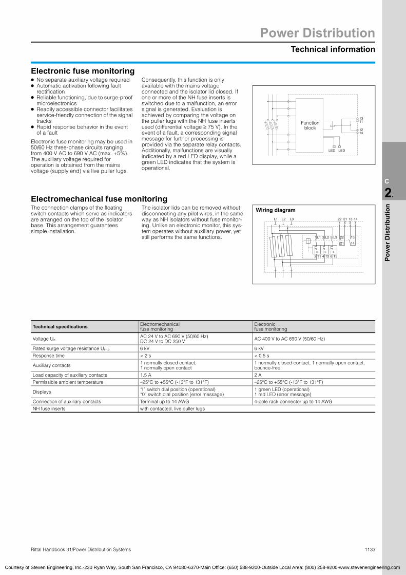
Technical information
Power Distribution
1133Rittal Handbook 31/Power Distribution Systems
C
2.
Pow
er D
istr
ibut
ion
22 21 13 14
22 13
21 14
1 3 5
2 4 6
L1 L2 L3
T1 T2 T3
L1 L2 L3
Wiring diagram
1214
1311
LED LED
Function block
Courtesy of Steven Engineering, Inc.-230 Ryan Way, South San Francisco, CA 94080-6370-Main Office: (650) 588-9200-Outside Local Area: (800) 258-9200-www.stevenengineering.com
Electronic fuse monitoring● No separate auxiliary voltage required Consequently, this function is only
● Automatic activation following faultrectification● Reliable functioning, due to surge-proof
microelectronics● Readily accessible connector facilitates
service-friendly connection of the signal tracks
● Rapid response behavior in the event of a fault
Electronic fuse monitoring may be used in 50/60 Hz three-phase circuits ranging from 400 V AC to 690 V AC (max. +5%). The auxiliary voltage required for operation is obtained from the mains voltage (supply end) via live puller lugs.
available with the mains voltage connected and the isolator lid closed. If one or more of the NH fuse inserts is switched due to a malfunction, an error signal is generated. Evaluation is achieved by comparing the voltage on the puller lugs with the NH fuse inserts used (differential voltage ≥ 75 V). In the event of a fault, a corresponding signal message for further processing is provided via the separate relay contacts. Additionally, malfunctions are visually indicated by a red LED display, while a green LED indicates that the system is operational.
Electromechanical fuse monitoringThe connection clamps of the floating switch contacts which serve as indicators are arranged on the top of the isolator base. This arrangement guarantees simple installation.
The isolator lids can be removed without disconnecting any pilot wires, in the same way as NH isolators without fuse monitor-ing. Unlike an electronic monitor, this sys-tem operates without auxiliary power, yet still performs the same functions.
Technical specifications Electromechanical fuse monitoring
Electronic fuse monitoring
Voltage Ue AC 24 V to AC 690 V (50/60 Hz)DC 24 V to DC 250 V AC 400 V to AC 690 V (50/60 Hz)
Rated surge voltage resistance Uimp 6 kV 6 kV
Response time < 2 s < 0.5 s
Auxiliary contacts 1 normally closed contact, 1 normally open contact
1 normally closed contact, 1 normally open contact, bounce-free
Load capacity of auxiliary contacts 1.5 A 2 A
Permissible ambient temperature –25°C to +55°C (-13°F to 131°F) –25°C to +55°C (-13°F to 131°F)
Displays “I” switch dial position (operational)“0” switch dial position (error message)
1 green LED (operational)1 red LED (error message)
Connection of auxiliary contacts Terminal up to 14 AWG 4-pole rack connector up to 14 AWG
NH fuse inserts with contacted, live puller lugs

Power DistributionTechnical information
1134 Rittal Handbook 31/Power Distribution Systems
C
2.
Pow
er D
istr
ibut
ion
Courtesy of Steven Engineering, Inc.-230 Ryan Way, South San Francisco, CA 94080-6370-Main Office: (650) 588-9200-Outside Local Area: (800) 258-9200-www.stevenengineering.com
NH fused isolators, sizes 00 to 3Pages 336, 349, 353
● The cable outlet – top or
bottom – is selected directly during assembly on the same device. The switch cover unit is rotated by 180° (sizes 1 to 3)● Reliable isolated or off-load position of the switch cover unit, due to the integral multi-function key
● Switch locking can be achieved with the installation of padlocks in the closed and isolated position
● For inspection purposes, there are viewing windows with integrated holes in the switch cover unit or sliding viewing windows
● Simple external/internal-mounting of microswitches to indicate the switch position of the NH unit (lid unit)
Technical specificationsto VDE 0660, part 107/IEC 60 947-3Size(NH fuse inserts to DIN 43 620) 00 1 2 3
Rated operating current Ie Conventional thermal current Ith
160 A160 A
250 A250 A
400 A400 A
630 A630 A
Voltage Ue AC 690 V
Rated insulation voltage Ui 800 V
Rated surge voltage resistance Uimp 8 kV
Conditional rated short-circuit current when protected with fuses 50 kA 50 kA 50 kA 50 kA
Rated breaking capacity to VDE 0660, part 107/IEC 60 947-3 (utilization category)
400 V AC-22BIe = 160 A
AC-22BIe = 250 A
AC-22BIe = 400 A
AC-22BIe = 630 A
690 V AC-21BIe = 160 A
AC-21BIe = 250 A
AC-21BIe = 400 A
AC-21BIe = 630 A
Mechanical life (switching cycles) 1600 1000 1000 1000
Permissible ambient temperature –25°C to +55°C (-13°F to 131°F)
Fire protection corresponding to UL 94-V0
Pv max./fuse insert 12 W 23 W 34 W 48 W
Use of semi-conductor fuses in Rittal NH switchgearThe overload and short-circuit protection of
semi-conductor components places very high demands on the fuse inserts, due to the time pattern for effective protection of the defective or damaged sub-circuit. Because semi-conductor components have a low thermal capacity, the integrated disconnect value (I2t-value) of the semi-conductor fuse inserts type aR, gR or gRL must match the integral limit value of the semi-conductor cell being protected. Consequently, the tripping characteristic of the fuse inserts must be very fast, and over-voltage during the disconnection process (switching or arc voltage) must be as minimal as possible. Compared with fuse inserts for cable and line protection and transformer protection, the particular features of semi-conductor fuse inserts produce a comparatively high heat loss. The high heat loss is dissipated to the environment in the form of thermal energy. Because NH switchgear has a limited capacity to dissipate thermal energy to the environment, the maximum heat loss (Pv max./fuse insert) is listed in the technical specifications of the NH switchgear. If the values exceed the heat loss specified by the manufacturer, the rated current should be reduced in accordance with the table opposite, or the minimum connection cross-section increased accordingly to encourage heat dissipation.Semi-conductor fuses type aR/gR/gRLMinimum cross-
section (Cu)AWG
Reduction factor for
rated currentSize IN[A]
Operating category
Heat loss[W]
00 25 gR 6 10 AWG 1.00
00 35 gR 9 8 AWG 1.00
00 50 gR 12 6 AWG 0.87
00 63 gR 15 4 AWG 0.87
00 80 aR 19 3 AWG 0.85
00 100 aR 21 1 AWG 0.85
00 125 aR 26 1/Ø AWG 0.80
00 160 aR 34 3/Ø AWG 0.75
1 160 gR 24 3/Ø AWG 1.00
1 200 gR 27 4/Ø AWG 1.00
1 250 gR 30 250 MCM 1.00
2 250 aR 105 250 MCM 0.77
2 315 aR 120 400 MCM 0.75
2 450 aR 140 2 x 300 MCM 0.75
3 150 gR 40 3/Ø AWG 0.90
3 200 gR 55 4/Ø AWG 0.90
3 250 gR 72 250 MCM 0.88
3 350 gR 95 500 MCM 0.81
3 500 gR 130 2 x 300 MCM 0.76

Technical information
Power Distribution
1135Rittal Handbook 31/Power Distribution Systems
C
2.
Pow
er D
istr
ibut
ion
65 65
210
11.5
256
270 24
1
6060
62.5
60
84
91
333
5 – 10 128.5
36.5
8023
256
270 24
1
6060
62.5
11.5
5 – 10
128.5
333
80
84
91
6036.5
23
210
65 65 11.5
72.5
256
270
241
6060
60
84
91
333
5 – 10 128.5
36.5
8023
207
62.5
256
270
241
6060
62.5
11.5
5 – 10
128.5
207
333
84
80
84
91
60
23
36.5
6062
.560
256
270
11.5
60
36.5
128.5
1605 – 10
80
84
91
333
23
241 60
60
256
270
6011
.5 128.5
1605 – 10
241
36.5
84
80
91
23
333
62.5
NH bus-mounting on-load isolator, size 2Page 340
SV 3415.020 SV 3415.030
SV 3415.120 SV 3415.130 SV 3415.210 SV 3415.230
8080
250
11.5
256
270
241
6060
62.5
60
84
91
335
5 – 10 133.5
36.5
8023
256
270
241
6060
62.5
11.5
5 – 10 133.5
335
80
84
91
60
36.5
23
250
80 80 11.5
76.5
256
270
241
6060
60
84
91
335
5 – 10 133.5
36.5
8023
211
62.5
256
270
241
6060
62.5
11.5
5 – 10
133.5
211
335
88
80
84
91
60
23
36.5
6062
.560
256
270
11.5
60
36.5
133.5
1655 – 10
80
84
91
335
23
241 60
60
256
270
6011
.5 133.5
1655 – 10
241
36.5
84
80
91
23
335
62.5
NH bus-mounting on-load isolator, size 3Page 341
SV 3095.020 SV 3095.030
SV 3095.120 SV 3095.130 SV 3095.210 SV 3095.230
Courtesy of Steven Engineering, Inc.-230 Ryan Way, South San Francisco, CA 94080-6370-Main Office: (650) 588-9200-Outside Local Area: (800) 258-9200-www.stevenengineering.com

Power DistributionTechnical information
1136 Rittal Handbook 31/Power Distribution Systems
C
2.
Pow
er D
istr
ibut
ion
NH on-load isolator, size 2Pages 347 and 359
210
65 65
128.5
36.5
84
80
91
333
6025
660
270
241
6565
210
256
60
333
36.5
128.5
203
84
270
91
84
80
60
241
65 65
210
270
256
60 44
36.5
128.5
160
91
241
84
333
60
80
SV 3415.010 SV 3415.110 SV 3415.310
NH on-load isolator, size 3Pages 348 and 359
8080
25091
335
84
36.5
80
133.5
270 241
6025
660
8080
250
335
241
88
80
84
91
133.5
207
270
36.5
6025
660
80 80
250
270
256
60 49
36.5
133.5
165
91
241
84
335
6080
SV 3095.010 SV 3095.110 SV 3095.310
NH on-load isolator, size 000 to 3Hole size Pages 358 and 359
64.5
50
7
110
75
180
150
SV 3488.000, SV 3488.310,SV 3489.000, SV 3489.310
SV 3431.000
Ø11
118
150
SV 3409.000,SV 3409.310
11
65 65
100
13
50
80 80
14
50
SV 3415.010SV 3415.110SV 3415.310
SV 3095.010SV 3095.110SV 3095.310
Courtesy of Steven Engineering, Inc.-230 Ryan Way, South San Francisco, CA 94080-6370-Main Office: (650) 588-9200-Outside Local Area: (800) 258-9200-www.stevenengineering.com

Technical information
Power Distribution
1137Rittal Handbook 31/Power Distribution Systems
C
2.
Pow
er D
istr
ibut
ion
Continuous currents for busbarsMade from E-Cu with square cross-section in indoor locations at 35°C (95°F) air temperature and 65°C (149°F) bar temperature, vertical position or horizontal position of the bar width.
Rittal PLS current loadAccording to DIN 43 671, the correction factor k2 (correction factor diagram) is used to correct the basic rated current with reference to the existing temperatures of the ambient air and the busbar.In accordance with DIN 43 671, the load figures of the Rittal PLS special bars have been determined on the basis of measurement trials, as follows:
Widthx
Thicknessmm
Cross-sectionmm2 Weight1) Material2)
Continuous current in A
AC current up to 60 Hz
DC current + AC current
16 Hz
Bare bar
Coated bar
Bare bar
Coated bar
12 x 2 23.5 0.209 108 123 108 123
15 x 2 29.5 0.262 128 148 128 148
15 x 3 44.5 0.396 162 187 162 187
20 x 2 39.5 0.351 162 189 162 189
20 x 3 59.5 0.529 204 237 204 237
20 x 5 99.1 0.882 274 319 274 320
20 x 10 199.0 1.770 427 497 428 499
25 x 3 74.5 0.663 245 287 245 287
25 x 5 124.0 1.110 327 384 327 384
30 x 3 89.5 0.796 285 337 286 337
30 x 5 149.0 1.330E-CuF30
379 447 380 448
30 x 10 299.0 2.660 573 676 579 683
40 x 3 119.0 1.060 366 435 367 436
40 x 5 199.0 1.770 482 573 484 576
40 x 10 399.0 3.550 715 850 728 865
50 x 5 249.0 2.220 583 697 588 703
50 x 10 499.0 4.440 852 1020 875 1050
60 x 5 299.0 2.660 688 826 696 836
60 x 10 599.0 5.330 985 1180 1020 1230
80 x 5 399.0 3.550 885 1070 902 1090
80 x 10 799.0 7.110 1240 1500 1310 15901) Calculated with a density of 8.9 kg/dm3
2) Reference basis for the continuous current levels (figures taken from DIN 43 671)
PLS special busbars
Basic rated current WS 50/60 Hz
For 35/75°C (95/167°F)
For 35/65°C (95/149°F)
E-Cu 800 A 800 A 684 A
E-Cu 1600 A 1600 A 1368 A
50 60 70 80 90 100 110 120
0.4
0.6
0.8
1.0
1.2
1.4
1.6
1.8
2.0
2.2 0
10
20
30
40
50
60
Fact
or k
2
Am
bien
t tem
pera
ture
[°C
]Busbar temperature [°C]
Correction factor diagramto DIN 43 671
0.6
0.8
1.0
1.2
0.4
1.4
1.6
2.0
1.8
50 60 70 80 90 100 110
0
10
20
30
40
50
60
70
Fact
or k
2
Ambi
ent t
empe
ratu
re [°
C]
Busbar temperature [°C]
Correction factor diagram for PLS
Courtesy of Steven Engineering, Inc.-230 Ryan Way, South San Francisco, CA 94080-6370-Main Office: (650) 588-9200-Outside Local Area: (800) 258-9200-www.stevenengineering.com
Rated currents of busbars E-Cu (DIN 43 671)DIN 43 671 specifies the continuous For the continuous temperatures specified in Example:
currents of busbars at an ambient temperature of 35°C (95°F) and an average busbar temperature of 65°C (149°F). The continuous currents specified in the following table may be adjusted to alternative operating temperatures using a correction factor (k2).For safe operation with thermal reserve, it is desirable to limit the busbar temperature to a maximum of 85°C (185°F). However, the decisive factor is the lowest permissible continuous temperature of the components which directly contact the busbar system (fuse bases, outgoing cables, etc.). The ambient air temperature of the busbars or the busbar system should not be more than 40°C (104°F); an average of 35°C (95°F) maximum is recommended.
the table, an emission level of 0.4 applies, equivalent to an oxidating copper bar. In modern busbar systems – built into enclosures with a protection category of IP 54 and above – a more favorable emission level can be assumed. The lower emission level facilitates an additional increase in continuous currents compared with the figures in DIN 43 671, irrespective of the specified air and busbar temperature. Experience has shown an increase in the continuous current of 6 – 10% compared with the table figures for bare copper bars, and 60% surface-oxidized copper bars.
For a Cu bar 30 x 10 mm (E-Cu F30), DIN 43 671 specifies a continuous current of IN65 = 573 A.The correction factor diagram for square cross-sections indicates a correction factor k2 = 1.29 at an air temperature of 35°C (95°F) and a busbar temperature of 85°C (185°F). Due to the favorable emission level, the continuous current is increased by a further 6 – 10%. In this example, a mean value of 8% is used. Compared with the table figure from DIN 43 671, the Rittal rated current specification for a Cu bar 30 x 10 mm is:
IN85 = IN65 · k2 + 8 % = 573 A · 1.29 · 1.08
IN85 = 800 A

Power DistributionRittal Maxi-PLS
1138 Rittal Handbook 31/Power Distribution Systems
C
2.
Pow
er D
istr
ibut
ion
2.8 System componentsMaxi-PLS 2000 A Page 376
51
2565
51
25
65
45.5
98.5
45
99.5
25
105
55
75
55 8
99.5
37
36
22
51
38
59
Maxi-PLS 3200 A Page 390
51
8025
60.5
60
80
148
25
70 50
70
130
100 50
8
434 50
54.5
L3 L2 L1
148
42.5
56
23
51
38
65.5
Courtesy of Steven Engineering, Inc.-230 Ryan Way, South San Francisco, CA 94080-6370-Main Office: (650) 588-9200-Outside Local Area: (800) 258-9200-www.stevenengineering.com
Busbar supports Part no. SV 9640.000, SV 9649.000
45.5
Busbar support, suitable for top-mountingPart no. SV 9640.160
50
End supportsPart no. SV 9640.010, SV 9649.010
51146
Busbar supports Part no. SV 9650.000, SV 9659.000
Busbar support, suitable for top-mountingPart no. SV 9650.160
60.5
End supportsPart no. SV 9650.010, SV 9659.010
Stabilizer Part no. SV 9650.140

Rittal Maxi-PLS
Power Distribution
1139Rittal Handbook 31/Power Distribution Systems
C
2.
Pow
er D
istr
ibut
ion
2.8 Connection componentsMaxi-PLS 2000 A Page 377
Maxi-PLS 3200 A Page 391
64
DD
BA
C E
22.5
723
RITTAL
M12 = 25Nm
M10 = 20Nm
90
58
45
11.3
24.8
14.8
B
8.3
17.8
10.8
A
405
A
B
C41
M10
40
9.5
A
M12
45
12.5
B
Courtesy of Steven Engineering, Inc.-230 Ryan Way, South San Francisco, CA 94080-6370-Main Office: (650) 588-9200-Outside Local Area: (800) 258-9200-www.stevenengineering.com
Isolator chassis
Connection clampPart no. SV 9640.320, SV 9650.320Part No. SV A B C D E
9640.020 89 61 346 100 89
9650.020 89 61 479 150 94
9650.030 129 101 479 150 94
Connection plates
Terminal studs(2000 A)T(
erminal studs3200 A)Sliding nuts(2000 A)
Sliding nuts(3200 A)
Part No. SV Size A B C T-head
screwsTightening
torque
9640.330 1 81 73 46 M10 177 in-lbs
9640.340 2 112 104 77 M10 211 in-lbs
9640.350 3 149 141 114 M10 266 in-lbs
9650.330 1 81 73 46 M12 211 in-lbs
9650.340 2 112 104 77 M12 266 in-lbs
9650.350 3 149 141 114 M12 310 in-lbs
Part No. SV A B
9640.370 M12 –
9640.380 M16 –
9650.370 – M12
9650.380 – M16
Part No. SV A B
9640.900 M6 –
9640.910 M8 –
9640.920 M10 –
9650.900 – M6
9650.910 – M10
9650.920 – M12

Power DistributionRittal Maxi-PLS
1140 Rittal Handbook 31/Power Distribution Systems
C
2.
Pow
er D
istr
ibut
ion
2.8 SV-TS8 enclosuresFor incoming/outgoing circuit 3-pole, page 392, 4-pole, page 393
2000
368.
5
468.
5
568.
5
693.
5
800
2000
368.
5
468.
5
568.
5
693.
5
268.
5
800
For NH fused isolators 3-pole, page 396
997
2000
1550
151.
527
3
225
225
300
300
300
525
553 ± 1
1197
2000
1550
151.
527
3
225
225
300
300
300 525
553 ± 1
Courtesy of Steven Engineering, Inc.-230 Ryan Way, South San Francisco, CA 94080-6370-Main Office: (650) 588-9200-Outside Local Area: (800) 258-9200-www.stevenengineering.com
3-pole
4-polePart No. SV
Widthmm (inches)
Depthmm (inches) Door(s)
9660.665 600 (23.6) 600 (23.6) 1
9660.675 600 (23.6) 600 (23.6) 3
9660.865 800 (31.5) 600 (23.6) 1
9660.875 800 (31.5) 600 (23.6) 3
Part No. SV
Widthmm (inches)
Depthmm (inches) Door(s)
9649.625 800 (31.5) 600 (23.6) 1
9649.635 800 (31.5) 600 (23.6) 3
9659.625 800 (31.5) 800 (31.5) 1
9659.635 800 (31.5) 800 (31.5) 3
Part No. SV Depthmm (inches) For1)
9660.515 600 (23.6) A
9660.415 600 (23.6) B1) NH fused isolators brand
A = ABB SlimLine B = Jean Müller SASIL
Part No. SV Depthmm (inches) For1)
9660.545 600 (23.6) A
9660.445 600 (23.6) B

Rittal Maxi-PLS
Power Distribution
1141Rittal Handbook 31/Power Distribution Systems
C
Pow
er
2.8 SV-TS8 enclosuresFor NH fused isolators 4-pole, page 397
JM
JM
JM
JM
JM
JM
1197
300
225
300
300
225
525
553 ± 1
1550
2000
151.
527
3
JM
JM
997
JM
JM
JM
JM
300
225
300
300
225
525
553 ± 1
1550
2000
151.
527
3
997
1550
2000
151.
527
3
300
300
300
225
225
525
553 ± 1
1197
1550
2000
151.
527
3
300
300
300
225
225
525
553 ± 1
12 45.5
4.240.2
138
14.2
50.2
140
35.212
75
45
75
45
10
10
T-bar supports up to 800 APart no. SV 9660.000/.010, SV 9649.100/.110
T-bar supports up to 1600 APart no. SV 9660.100/.110, SV 9659.100/.110
T-busbars E-Cu up to 800 A Part no. SV 9660.020/.030, SV 9649.120/.130
T-busbars E-Cuup to 1600 A Part no. SV 9660.120/.130, SV9659.120/.130
Courtesy of Steven Engineering, Inc.-230 Ryan Way, South San Francisco, CA 94080-6370-Main Office: (650) 588-9200-Outside Local Area: (800) 258-9200-www.stevenengineering.com
Part No. SV
Depthmm (inches) For1)
9649.645 600 (23.6) B
9659.645 800 (31.5) B1) NH-fused isolators brand A = ABB SlimLine, B
Part SV
9649.
9659.
= Jean Müller SASIL
No. Depthmm (inches) For1)
655 600 (23.6) B
655 800 (31.5) B
Part NoSV
9649.66
9659.66
Part NoSV
9649.675
9659.675
. Depthmm (inches) For1)
5 600 (23.6) A
5 800 (31.5) A
2.
Dis
trib
utio
n
. Depthmm (inches) For1)
600 (23.6) A
800 (31.5) A
For coupling sets Page 399
B
800
693.
5
997
712
2000
AA
693.
5
800
B
797
512
2000
Part No. SV
Depthmm (inches)
Amm
Bmm
9660.305 600 (23.6) 418.5 418.5
Part No. SV
Depthmm (inches)
Amm
Bmm
9660.355 600 (23.6) 443.5 468.5
9649.685 600 (23.6) 418.5 418.5
9659.695 800 (31.5) 443.5 468.5
System components for NH fused isolators panels Page 398
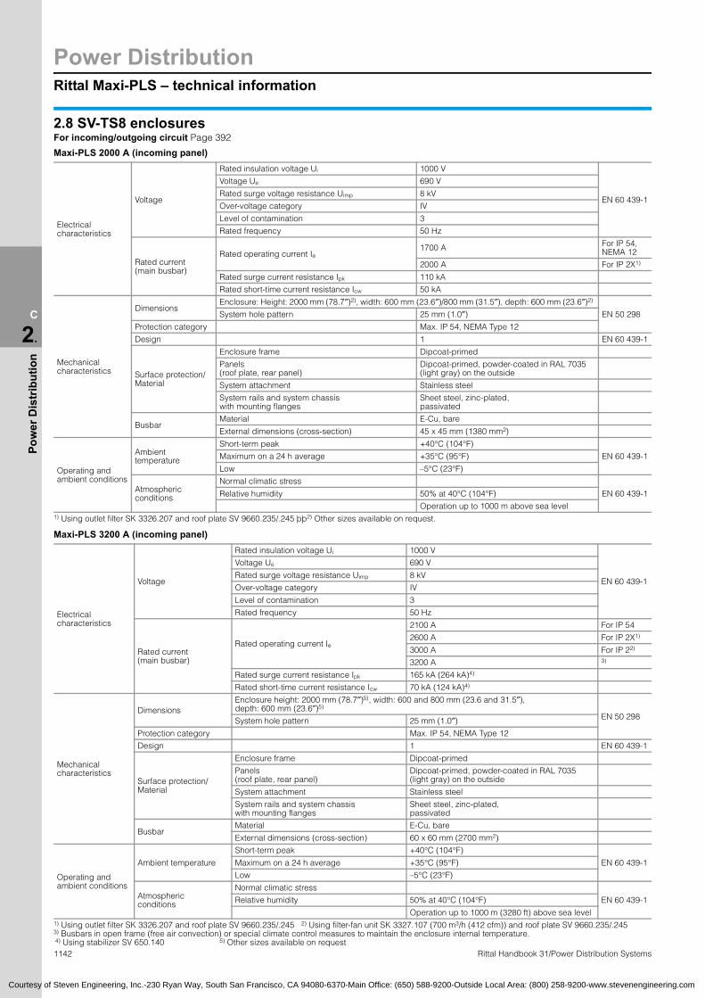
Power DistributionRittal Maxi-PLS – technical information
1142 Rittal Handbook 31/Power Distribution Systems
C
2.
Pow
er D
istr
ibut
ion
2.8 SV-TS8 enclosuresFor incoming/outgoing circuit Page 392
Maxi-PLS 2000 A (incoming panel)
Maxi-PLS 3200 A (incoming panel)
Electrical characteristics
Voltage
Rated insulation voltage Ui 1000 V
EN 60 439-1
Voltage Ue 690 V
Rated surge voltage resistance Uimp 8 kV
Over-voltage category IV
Level of contamination 3
Rated frequency 50 Hz
Rated current(main busbar)
Rated operating current Ie 1700 A For IP 54,
NEMA 12
2000 A For IP 2X1)
Rated surge current resistance Ipk 110 kA
Rated short-time current resistance Icw 50 kA
Mechanical characteristics
DimensionsEnclosure: Height: 2000 mm (78.7″)2), width: 600 mm (23.6″)/800 mm (31.5″), depth: 600 mm (23.6″)2)
EN 50 298System hole pattern 25 mm (1.0″)
Protection category Max. IP 54, NEMA Type 12
Design 1 EN 60 439-1
Surface protection/Material
Enclosure frame Dipcoat-primed
Panels (roof plate, rear panel)
Dipcoat-primed, powder-coated in RAL 7035 (light gray) on the outside
System attachment Stainless steel
System rails and system chassis with mounting flanges
Sheet steel, zinc-plated, passivated
BusbarMaterial E-Cu, bare
External dimensions (cross-section) 45 x 45 mm (1380 mm2)
Operating and ambient conditions
Ambient temperature
Short-term peak +40°C (104°F)
EN 60 439-1Maximum on a 24 h average +35°C (95°F)
Low –5°C (23°F)
Atmospheric conditions
Normal climatic stress
EN 60 439-1Relative humidity 50% at 40°C (104°F)
Operation up to 1000 m above sea level1) Using outlet filter SK 3326.207 and roof plate SV 9660.235/.245 þþ2) Other sizes available on request.
Electrical characteristics
Voltage
Rated insulation voltage Ui 1000 V
EN 60 439-1
Voltage Ue 690 V
Rated surge voltage resistance Uimp 8 kV
Over-voltage category IV
Level of contamination 3
Rated frequency 50 Hz
Rated current(main busbar)
Rated operating current Ie
2100 A For IP 54
2600 A For IP 2X1)
3000 A For IP 22)
3200 A 3)
Rated surge current resistance Ipk 165 kA (264 kA)4)
Rated short-time current resistance Icw 70 kA (124 kA)4)
Mechanical characteristics
DimensionsEnclosure height: 2000 mm (78.7″)5), width: 600 and 800 mm (23.6 and 31.5″), depth: 600 mm (23.6″)5)
EN 50 298System hole pattern 25 mm (1.0″)
Protection category Max. IP 54, NEMA Type 12
Design 1 EN 60 439-1
Surface protection/Material
Enclosure frame Dipcoat-primed
Panels (roof plate, rear panel)
Dipcoat-primed, powder-coated in RAL 7035 (light gray) on the outside
System attachment Stainless steel
System rails and system chassis with mounting flanges
Sheet steel, zinc-plated, passivated
BusbarMaterial E-Cu, bare
External dimensions (cross-section) 60 x 60 mm (2700 mm2)
Operating and ambient conditions
Ambient temperature
Short-term peak +40°C (104°F)
EN 60 439-1Maximum on a 24 h average +35°C (95°F)
Low –5°C (23°F)
Atmospheric conditions
Normal climatic stress
EN 60 439-1Relative humidity 50% at 40°C (104°F)
Operation up to 1000 m (3280 ft) above sea level1) Using outlet filter SK 3326.207 and roof plate SV 9660.235/.245 2) Using filter-fan unit SK 3327.107 (700 m3/h (412 cfm)) and roof plate SV 9660.235/.245 3) Busbars in open frame (free air convection) or special climate control measures to maintain the enclosure internal temperature. 4) Using stabilizer SV 650.140 5) Other sizes available on request
Courtesy of Steven Engineering, Inc.-230 Ryan Way, South San Francisco, CA 94080-6370-Main Office: (650) 588-9200-Outside Local Area: (800) 258-9200-www.stevenengineering.com

Rittal Maxi-PLS – technical information
Power Distribution
1143Rittal Handbook 31/Power Distribution Systems
C
2.
Pow
er D
istr
ibut
ion
2.8 SV-TS8 enclosuresFor NH fused isolators Page 394
Maxi-PLS 2000 A (185 mm (7.3″) busbar system in the rear section of the enclosure)
Maxi-PLS 3200 A (185 mm busbar system in the rear section of the enclosure)
Electrical characteristics
Voltage
Rated insulation voltage Ui 1000 V
EN 60 439-1
Voltage Ue 690 V
Rated surge voltage resistance Uimp 8 kV
Over-voltage category IV
Level of contamination 3
Rated frequency 50 Hz
Rated current(main busbar)
Rated operating current Ie 1700 A For IP 54
2000 A For IP 2X1)
Rated surge current resistance Ipk 143 kA2)
Rated short-time current resistance Icw 65 kA2)
Mechanical characteristics
DimensionsEnclosure height: 2000 mm (78.7″)3), widths: 600, 800, 1000 and 1200 mm (23.6, 31.5, 39.4 and 47.2″), depths: 500, 600 and 800 mm (19.7, 23.6 and 31.5″)
EN 50 298System hole pattern 25 mm (1.0″)
Protection category Max. IP 54, NEMA Type 12
Design 1 EN 60 439-1
Surface protection/Material
Enclosure frame Dipcoat-primed
Panels (roof plate, rear panel)
Dipcoat-primed, powder-coated in RAL 7035 (light gray) on the outside
System attachment Stainless steel
System rails and system chassis with mounting flanges
Sheet steel, zinc-plated, passivated
BusbarMaterial E-Cu, bare
External dimensions (cross-section) 45 x 45 mm (1380 mm2)
Operating and ambient conditions
Ambient temperature
Short-term peak +40°C (104°F)
EN 60 439-1Maximum on a 24 h average +35°C (95°F)
Low –5°C (23°F)
Atmospheric conditions
Normal climatic stress
EN 60 439-1Relative humidity 50% at 40°C (104°F)
Operation up to 1000 m above sea level
Electrical characteristics
Voltage
Rated insulation voltage Ui 1000 V
EN 60 439-1
Voltage Ue 690 V
Rated surge voltage resistance Uimp 8 kV
Over-voltage category IV
Level of contamination 3
Rated frequency 50 Hz
Rated current(main busbar)
Rated operating current Ie
2100 A For IP 54
2600 A For IP 2X1)
3000 A For IP 2X4)
3200 A 5)
Rated surge current resistance Ipk 176 kA6)
Rated short-time current resistance Icw 80 kA6)
Mechanical characteristics
DimensionsEnclosure height: 2000 mm (78.7″)3), widths: 600, 800, 1000 and 1200 mm (23.6, 31.5, 39.4 and 47.2″), depths: 500, 600 and 800 mm (19.7, 23.6 and 31.5″)
EN 50 298System hole pattern 25 mm (1.0″)
Protection category Max. IP 54, NEMA Type 12
Design 1 EN 60 439-1
Surface protection/Material
Enclosure frame Dipcoat-primed
Panels (roof plate, rear panel)
Dipcoat-primed, powder-coated in RAL 7035 (light gray) on the outside
System attachment Stainless steel
System rails and system chassis with mounting flanges
Sheet steel, zinc-plated, passivated
BusbarMaterial E-Cu, bare
External dimensions (cross-section) 60 x 60 mm (2,700 mm2)
Operating and ambient conditions
Ambient temperature
Short-term peak +40°C (104°F)
EN 60 439-1Maximum on a 24 h average +35°C (95°F)
Low –5°C (23°F)
Atmospheric conditions
Normal climatic stress
EN 60 439-1Relative humidity 50% at 40°C (104°F)
Operation up to 1000 m above sea level1) Using outlet filter SK 3326.207 and roof plate SV 9660.235/.245/.255/.265 2) Using busbar support, suitable for top-mounting SV 9640.160 3) Enclosure height 1800 and 2200 mm (70.9 and 86.6″) available on request 4) Using filter-fan unit SK 3327.107 (700 m3/h (412 cfm)) and roof plate SV 9660.235/.245/.255/.265 5) Busbars in open frame (free air convection) or special climate control measures to maintain the enclosure internal temperature 6) Using busbar support, suitable for top-mounting SV 9650.160
Courtesy of Steven Engineering, Inc.-230 Ryan Way, South San Francisco, CA 94080-6370-Main Office: (650) 588-9200-Outside Local Area: (800) 258-9200-www.stevenengineering.com

Power DistributionRittal Maxi-PLS – technical information
1144 Rittal Handbook 31/Power Distribution Systems
C
2.
Pow
er D
istr
ibut
ion
2.8 SV-TS8 enclosuresFor NH fused isolators Page 396
T-bar system 800 A
T-bar system 1600 A
Electrical characteristics
Voltage
Rated insulation voltage Ui 1000 V
EN 60 439-1
Voltage Ue 690 V
Rated surge voltage resistance Uimp 8 kV
Over-voltage category IV
Level of contamination 3
Rated frequency 50 Hz
Rated current(main busbar)
Rated operating current Ie 1000 A For IP 3X
Rated surge current resistance Ipk 110 kA
Rated short-time current resistance Icw 50 kA
Mechanical characteristics
DimensionsEnclosure height: 2000 mm (78.7″)1), width: 1000 mm (39.4″) and 1200 mm (47.2″), depth: 600 mm (23.6″)1)
EN 50 298System hole pattern 25 mm (1.0″)
Protection category IP 3X
Design 1 EN 60 439-1
Surface protection/Material
Enclosure frame Dipcoat-primed
Panels (roof plate, rear panel)
Dipcoat-primed, powder-coated in RAL 7035 (light gray) on the outside
System rails and system chassis with mounting flanges
Sheet steel, zinc-plated, passivated
System attachment Stainless steel
Busbar
Material E-Cu, bare
Width contact strip 10 mm
Cross-section 470 mm2
Operating and ambient conditions
Ambient temperature
Short-term peak +40°C (104°F)
EN 60 439-1Maximum on a 24 h average +35°C (95°F)
Low –5°C (23°F)
Atmospheric conditions
Normal climatic stress
EN 60 439-1Relative humidity 50% at 40°C (104°F)
Operation up to 1000 m above sea level1) Other sizes available on request
Electrical characteristics
Voltage
Rated insulation voltage Ui 1000 V
EN 60 439-1
Voltage Ue 690 V
Rated surge voltage resistance Uimp 8 kV
Over-voltage category IV
Level of contamination 3
Rated frequency 50 Hz
Rated current(main busbar)
Rated operating current Ie 1600 A For IP 3X
Rated surge current resistance Ipk 110 kA
Rated short-time current resistance Icw 50 kA
Mechanical characteristics
DimensionsEnclosure height: 2000 mm (78.7″)1), width: 1000 mm (39.4″) and 1200 mm (47.2″), depth: 600 mm (23.6″)1)
EN 50 298System hole pattern 25 mm (1.0″)
Protection category IP 3X
Design 1 EN 60 439-1
Surface protection/Material
Enclosure frame Dipcoat-primed
Panels (roof plate, rear panel)
Dipcoat-primed, powder-coated in RAL 7035 (light gray) on the outside
System rails and system chassis with mounting flanges
Sheet steel, zinc-plated, passivated
System attachment Stainless steel
Busbar
Material E-Cu, bare
Width contact strip 10 mm
Cross-section 910 mm2
Operating and ambient conditions
Ambient temperature
Short-term peak +40°C (104°F)
EN 60 439-1Maximum on a 24 h average +35°C (95°F)
Low –5°C (23°F)
Atmospheric conditions
Normal climatic stress
EN 60 439-1Relative humidity 50% at 40°C (104°F)
Operation up to 1000 m above sea level1) Other sizes available on request
Courtesy of Steven Engineering, Inc.-230 Ryan Way, South San Francisco, CA 94080-6370-Main Office: (650) 588-9200-Outside Local Area: (800) 258-9200-www.stevenengineering.com

Rittal Maxi-PLS – technical information
Power Distribution
1145Rittal Handbook 31/Power Distribution Systems
C
2.
Pow
er D
istr
ibut
ion
2.8 SV-TS8 enclosuresFor coupling sets Page 399
Maxi-PLS 2000 A (coupling section)
Maxi-PLS 3200 A (coupling section)
Electrical characteristics
Voltage
Rated insulation voltage Ui 1000 V
EN 60 439-1
Voltage Ue 690 V
Rated surge voltage resistance Uimp 8 kV
Over-voltage category IV
Level of contamination 3
Rated frequency 50 Hz
Rated current(main busbar)
Rated operating current Ie 1700 A For IP 54
2000 A For IP 2X1)
Rated surge current resistance Ipk 110 kA
Rated short-time current resistance Icw 50 kA
Mechanical characteristics
DimensionsEnclosure height: 2000 mm (78.7″)2), width: 800 mm (31.5″)2), depth: 600 mm (23.6″)2)
EN 50 298System hole pattern 25 mm (1.0″)
Protection category Max. IP 54, NEMA Type 12
Design 1 EN 60 439-1
Surface protection/Material
Enclosure frame Dipcoat-primed
Panels (roof plate, rear panel)
Dipcoat-primed, powder-coated in RAL 7035 (light gray) on the outside
System attachment Stainless steel
System rails and system chassis with mounting flanges
Sheet steel, zinc-plated, passivated
BusbarMaterial E-Cu, bare
External dimensions (cross-section) 45 x 45 mm (1380 mm2)
Operating and ambient conditions
Ambient temperature
Short-term peak +40°C (104°F)
EN 60 439-1Maximum on a 24 h average +35°C (95°F)
Low –5°C (23°F)
Atmospheric conditions
Normal climatic stress
EN 60 439-1Relative humidity 50% at 40°C (104°F)
Operation up to 1000 m above sea level1) Using outlet filter SK 3326.207 and roof plate SV 9660.2452) Other sizes available on request
Electrical characteristics
Voltage
Rated insulation voltage Ui 1000 V
EN 60 439-1
Voltage Ue 690 V
Rated surge voltage resistance Uimp 8 kV
Over-voltage category IV
Level of contamination 3
Rated frequency 50 Hz
Rated current(main busbar)
Rated operating current Ie
2100 A For IP 54
2600 A For IP 2X1)
3000 A For IP 2X2)
3200 A 3)
Rated surge current resistance Ipk 110 kA
Rated short-time current resistance Icw 50 kA
Mechanical characteristics
DimensionsEnclosure: height: 2000 mm (78.7″)4), width: 1000 mm (39.4″)4), depth: 600 mm (23.6″)4)
EN 50 298System hole pattern 25 mm (1.0″)
Protection category Max. IP 54, NEMA Type 12
Design 1 EN 60 439-1
Surface protection/Material
Enclosure frame Dipcoat-primed
Panels (roof plate, rear panel)
Dipcoat-primed, powder-coated in RAL 7035 (light gray) on the outside
System attachment Stainless steel
System rails and system chassis with mounting flanges
Sheet steel, zinc-plated, passivated
BusbarMaterial E-Cu, bare
External dimensions (cross-section) 60 x 60 mm (2700 mm2)
Operating and ambient conditions
Ambient temperature
Short-term peak +40°C (104°F)
EN 60 439-1Maximum on a 24 h average +35°C (95°F)
Low –5°C (23°F)
Atmospheric conditions
Normal climatic stress
EN 60 439-1Relative humidity 50% at 40°C (104°F)
Operation up to 1000 m above sea level1) Using outlet filter SK 3326.207 and roof plate SV 9660.255 2) Using filter-fan unit SK 3327.107 (700 m3/h (412 cfm)) and roof plate SV 9660.255 3) Busbars in open frame (free air convection) or special climate control measures to maintain the enclosure internal temperature 4) Other sizes available on request
Courtesy of Steven Engineering, Inc.-230 Ryan Way, South San Francisco, CA 94080-6370-Main Office: (650) 588-9200-Outside Local Area: (800) 258-9200-www.stevenengineering.com

Power DistributionRittal Maxi-PLS – technical information
C
2.
Pow
er D
istr
ibut
ion
Courtesy of Steven Engineering, Inc.-230 Ryan Way, South San Francisco, CA 94080-6370-Main Office: (650) 588-9200-Outside Local Area: (800) 258-9200-www.stevenengineering.com
Planning and project management in line with regulationsAs a general principle, low-voltage switchgear and distributors should be planned to meet the operating conditions of their final installation site. The operator of the plant should therefore, in collaboration with the manufacturer, stipulate the operating and ambient conditions. As a general rule, the operator or planning office should also supply the manufacturer with full electrical specifications of both the mains supply end and the distributor outlet end. This makes it possible to plan and manufacture a cost-effective system with optimum adaptation to the technical requirements.
Important operating and ambient conditions● Voltage Ue ● Mains frequency fN ● Rated insulation voltage Ui ● Busbar rated current Isas ● Rated current for the supply end Izu ● Rated surge current resistance Ipk ● Rated short-time current resistance Icw ● Ambient temperature condition ϑ ● Atmospheric climatic stress, specifying
the relative humidity and temperature● Protection category of the overall system
IP . . . ● Specification to DIN EN 60 529 ● Protection category
Important basic data for planning and project management● Applicable regulations and standards,
both regional and international● Electric supply company conditions● Operator-specific regulations● Mains-specific protective measures/mains
type● Voltage and frequency● Rated current with regard for the number
of conductors (infeed and busbars)● Rated insulation voltage● Short-circuit current at the point of
installation● Location of incoming cables, from above
or below● Number of incoming cables and wires,
specifying the type and cross-section● Number of outlets, specifying the
operating load and the envisaged outgoing cables with type and cross-section
● For the outlet side, specification of the simultaneity factor and rated load factor of the relevant equipment items
Rated load factorThe rated load factor of a switchgear Number of
enclosure or part thereof (e.g. a field) comprising several main circuits refers to the ratio between the largest sum total of all currents anticipated at any given time in the affected main circuits and the sum total of the rated currents of all main circuits of the switchgear enclosure or observed part thereof.main circuits Load factor
2 and 3 0.9
4 and 5 0.8
6 and 7 0.7
10 or more 0.6
1146 Rittal Handbook 31/Power Distribution Systems
Rated currents and short-circuit currents of standard transformers Voltage
UN = 400 V 400 V
Short-circuit voltage Uk 4%1) 6%2)
Power consumption SNT [kVA]
Rated current IN [A]
Short-circuit current Ik''3) [kA]
50 72 1.89 1.20
100 144 3.61 2.41
160 230 5.77 3.85
200 288 7.22 4.81
250 360 9.02 6.01
315 455 11.36 7.58
400 589 14.43 9.62
500 722 18.04 12.03
630 910 22.73 15.15
800 1156 28.86 19.24
1000 1444 36.08 24.05
1250 1805 45.09 30.06
1600 2312 57.72 38.48
2000 2882 72.15 48.101) Uk = 4% standardized to DIN 42 503 for SNT = 50 . . . 630 kVA2) Uk = 6% standardized to DIN 42 511 for SNT = 100 . . . 1600 kVA3) Ik'' = Initial symmetrical short-circuit current of transformer when connecting to a mains supply with unlimited short-circuit lead
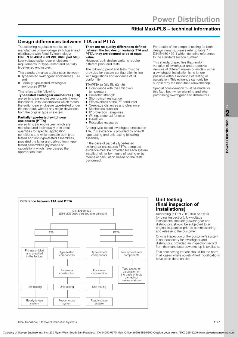
Rittal Maxi-PLS – technical information
Power Distribution
1147Rittal Handbook 31/Power Distribution Systems
C
2.
Pow
er D
istr
ibut
ion
Courtesy of Steven Engineering, Inc.-230 Ryan Way, South San Francisco, CA 94080-6370-Main Office: (650) 588-9200-Outside Local Area: (800) 258-9200-www.stevenengineering.com
The following regulation applies to the There are no quality differences defined For details of the scope of testing for both Design differences between TTA and PTTA
manufacture of low-voltage switchgear and distributors with Rittal SV technology: DIN EN 60 439-1 (DIN VDE 0660 part 500)Low-voltage switchgear enclosures – requirements for type-tested and partially type-tested enclosures.This standard makes a distinction between● Type-tested switchgear enclosures (TTA)
and● Partially type-tested switchgear
enclosures (PTTA)
This refers to the following: Type-tested switchgear enclosures (TTA) are switchgear enclosures or parts thereof (functional units, assemblies) which match the switchgear enclosure type-tested under the standard, without any major deviations from the original type or system.
Partially type-tested switchgear enclosures (PTTA)are switchgear enclosures which are manufactured individually or in small quantities for specific application conditions and which contain both type-tested and non-type-tested assemblies, provided the latter are derived from type-tested assemblies (by means of calculation) which have passed the appropriate tests.
between the two design variants TTA and PTTA, they are deemed to be of equal value.However, both design variants require different proof and tests.
The following proof and tests must be provided for system configuration in line with regulations and evidence of CE conformity:
TTA/PTTA to DIN EN 60 439-1● Compliance with the limit over-
temperature● Dielectric strength● Short-circuit resistance ● Effectiveness of the PE conductor● Creepage distances and clearance● Mechanical function● IP protection categories● Wiring, electrical function● Insulation● Protective measures
Among type-tested switchgear enclosures TTA, this evidence is provided by one-off type testing and unit testing following assembly.
In the case of partially type-tested switchgear enclosures PTTA, complete evidence must be provided for each system installed, either by means of testing or by means of calculation based on the tests performed.
design variants, please refer to table 7 in DIN EN 60 439-1 which contains references to the standard section number.
This standard specifies that random variation of switchgear and protective devices of different makes or models within a switchgear installation is no longer possible without evidence of testing or calculation. This evidence can only be supplied by the manufacturer/workshop.
Special consideration must be made for this fact, both when planning and when purchasing switchgear and distributors.
Difference between TTA and PTTA
DIN EN 60 439-1 (DIN VDE 0660 part 500 and part 504)
TTA
PTTAPre-assembled and prewired in the factory
Type-tested components
Type-tested components
Non-type-tested components
Enclosure construction
Enclosure construction
Type testing or calculation on
the basis of tests carried out
(extrapolation)
Unit testing
Unit testing Unit testingReady-to-use system
Ready-to-use system
Ready-to-use system
Unit testing(final inspection of installations)According to DIN VDE 0100 part 610 (original inspection), low-voltage installations, including switchgear and distributors, should be subjected to an original inspection prior to commissioning and release to the customer.
On-site inspection of the customer’s system is not necessary for switchgear and distributors, provided an inspection record from the manufacturer/workshop is available.
This cost-saving variant should be the norm in all cases where no retrofitted modifications have been done on site.

Power DistributionISV distribution enclosure
1148 Rittal Handbook 31/Power Distribution Systems
C
2.
Pow
er D
istr
ibut
ion
2.9 ISV-TS8 enclosuresFor ISV installation distribution enclosure up to 630 A Page 409
Width measurements Part No. SVB1 B2 B3 B4 B5 B6 B7 B8 B9
597 592 512 606 475 455 605 512 440 9665.905847 842 762 856 725 705 605 512 690 9665.9151097 1092 1012 1106 975 955 605 512 940 9665.925597 592 512 606 475 455 405 312 440 9665.945847 842 762 856 725 705 405 312 690 9665.9551097 1092 1012 1106 975 955 405 312 940 9665.965
Technical specifications Rated current up to 400 A 630 A
Rated surge current resistance Ipk at a maximum busbar sup-port centre distance of 300 mm
30 kA 45 kA
Rated insulation voltage Ui to VDE 0110 690 V AC
cos phi 0.3
Cross-section of phase conductor L1 – L3 30 x 5 mm 30 x 10 mm
Cross-section of neutral conductor N 25 x 10 mm 25 x 10 mm
Cross-section of ground wire 12 x 10 mm 12 x 10 mm
Protective measures Protection category 1(with ground wire)
Over-voltage category 3 3
IP protection categoryIP 20 (NEMA Type1)
without door, IP 55 (NEMA Type 12) with door
B1 B1
B7
1912
100
150
203
B5
30 61
61 30
B3
B2
B9
B7
B8
B4
Top view with side panels shown (B4).
appr
ox. 2
000
(78.
7″)
For ISV distribution enclosures up to 1600 A Page 410
61
30
725
605
690
61
30
512
762
842
847
605
317
705
705
640
1518
.5
1293
.5
643.
5
518.
5
475 61
3030
61
592
512
605
440
512
597
appr
ox. 2
000
(78.
7″)
appr
ox. 2
000
(78.
7″)
Courtesy of Steven Engineering, Inc.-230 Ryan Way, South San Francisco, CA 94080-6370-Main Office: (650) 588-9200-Outside Local Area: (800) 258-9200-www.stevenengineering.com
SV 9665.975
SV 9665.985
Electronic Packaging
1149Rittal Handbook 31/Electronic Systems
C
3.
Elec
Pac
kagi
ng
FRONT BOARD(8 U x 2800 (110.2″) x 6 HP)
RTM
(8 U
x 7
00 (2
7.6″
) x 6
HP)
Courtesy of Steven Engineering, Inc.-230 Ryan Way, South San Francisco, CA 94080-6370-Main Office: (650) 588-9200-Outside Local Area: (800) 258-9200-www.stevenengineering.com
3.1 ATCAAdvancedTCA Shelf Pages 426/427
Front view, version VA
Rear view, version VA/VBAir routing, version VA/VB
tron
ic
EMC provision, version VA/VB
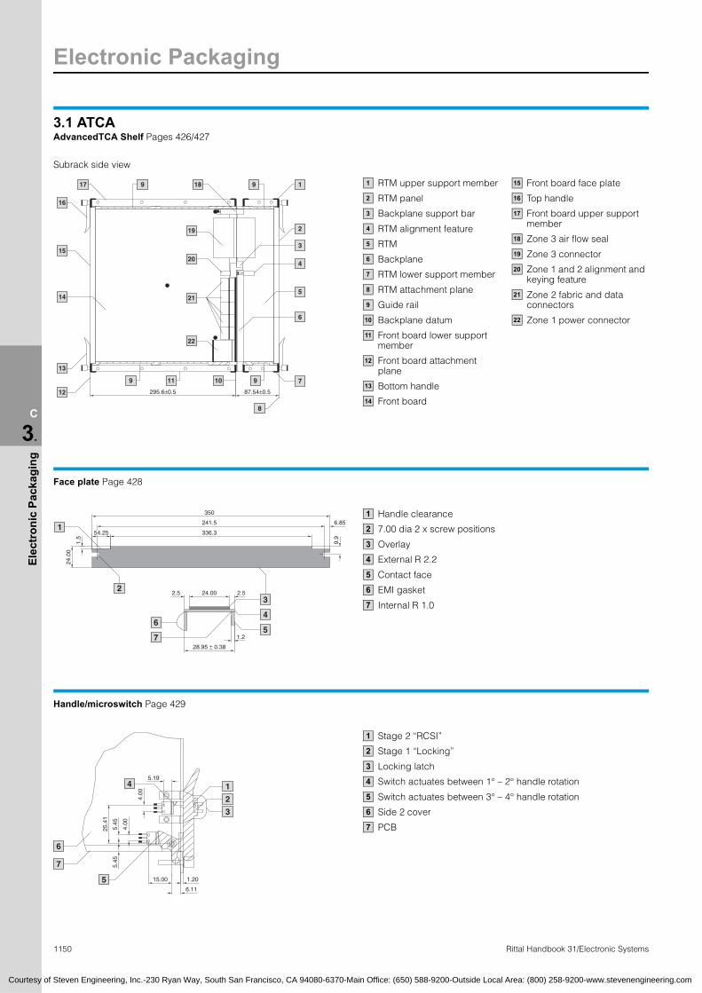
Electronic Packaging
1150 Rittal Handbook 31/Electronic Systems
C
3.
Elec
tron
ic P
acka
ging
295.6±0.5 87.54±0.5
17 9 18
19
20
21
22
9 1
2
3
4
5
6
7
8
9109 11
12
13
14
15
16
350
241.5
336.3
6.85
54.25
28.95 ± 0.38
1.2
24.00 2.52.5
24.0
0
1.5
9.9
1
3
4
5
2
6
7
15.00
5.19
25.4
1
6.11
1.20
4.00
4.00
5.45
5.45
1
3
2
4
5
6
7
Courtesy of Steven Engineering, Inc.-230 Ryan Way, South San Francisco, CA 94080-6370-Main Office: (650) 588-9200-Outside Local Area: (800) 258-9200-www.stevenengineering.com
3.1 ATCAAdvancedTCA Shelf Pages 426/427
Subrack side view
RTM upper support member
RTM panel
Backplane support bar
RTM alignment feature
RTM
Backplane
RTM lower support member
RTM attachment plane
Guide rail
Backplane datum
Front board lower support member
Front board attachment plane
Bottom handle
Front board
Front board face plate
Top handle
Front board upper support member
Zone 3 air flow seal
Zone 3 connector
Zone 1 and 2 alignment and keying feature
Zone 2 fabric and data connectors
Zone 1 power connector
1
2
3
4
5
6
7
8
9
10
11
12
13
14
15
16
17
18
19
20
21
22
Face plate Page 428
Handle clearance
7.00 dia 2 x screw positions
Overlay
External R 2.2
Contact face
EMI gasket
Internal R 1.0
1
2
3
4
5
6
7
Handle/microswitch Page 429
Stage 2 “RCSI”
Stage 1 “Locking”
Locking latch
Switch actuates between 1° – 2° handle rotation
Switch actuates between 3° – 4° handle rotation
Side 2 cover
PCB
1
2
3
4
5
6
7
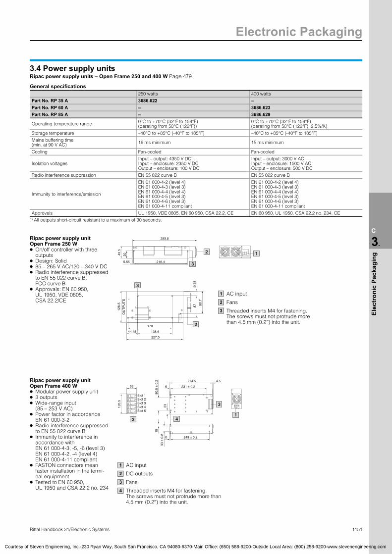
Electronic Packaging
1151Rittal Handbook 31/Electronic Systems
C
3.
Elec
tron
ic P
acka
ging
178
19.7
5
OU
TP
UT
S
227.5
138.6
126.
5
44.45
87 90.7
3
2
149.5
5.55 216.4
30
2
3
Slot 1
63
126.
5 Slot 2Slot 3Slot 4Slot 5
2
23
80.5
± 0
.2
6 231 ± 0.2
274.5 4.5
33 ±
0.2 6 249 ± 0.2
15
3
4
N L
1
Courtesy of Steven Engineering, Inc.-230 Ryan Way, South San Francisco, CA 94080-6370-Main Office: (650) 588-9200-Outside Local Area: (800) 258-9200-www.stevenengineering.com
3.4 Power supply unitsRipac power supply units – Open Frame 250 and 400 W Page 479
General specifications 250 watts 400 watts
Part No. RP 35 A 3686.622 –
Part No. RP 60 A – 3686.623
Part No. RP 85 A – 3686.629
Operating temperature range 0°C to +70°C (32°F to 158°F)(derating from 50°C (122°F))
0°C to +70°C (32°F to 158°F) (derating from 50°C (122°F), 2.5%/K)
Storage temperature –40°C to +85°C (-40°F to 185°F) –40°C to +85°C (-40°F to 185°F)
Mains buffering time (min. at 90 V AC) 16 ms minimum 15 ms minimum
Cooling Fan-cooled Fan-cooled
Isolation voltagesInput – output: 4350 V DCInput – enclosure: 2350 V DCOutput – enclosure: 100 V DC
Input – output: 3000 V ACInput – enclosure: 1500 V ACOutput – enclosure: 500 V DC
Radio interference suppression EN 55 022 curve B EN 55 022 curve B
Immunity to interference/emission
EN 61 000-4-2 (level 4) EN 61 000-4-3 (level 3) EN 61 000-4-4 (level 4) EN 61 000-4-5 (level 3) EN 61 000-4-6 (level 3) EN 61 000-4-11 compliant
EN 61 000-4-2 (level 4) EN 61 000-4-3 (level 3) EN 61 000-4-4 (level 4) EN 61 000-4-5 (level 3) EN 61 000-4-6 (level 3) EN 61 000-4-11 compliant
Approvals UL 1950, VDE 0805, EN 60 950, CSA 22.2, CE EN 60 950, UL 1950, CSA 22.2 no. 234, CE1) All outputs short-circuit resistant to a maximum of 30 seconds.
Ripac power supply unit 259.5
Open Frame 250 W ● On/off controller with three
outputs● Design: Solid● 85 – 265 V AC/120 – 340 V DC● Radio interference suppressed
to EN 55 022 curve B, FCC curve B
● Approvals: EN 60 950, UL 1950, VDE 0805, CSA 22.2/CE
Ripac power supply unit Open Frame 400 W ● Modular power supply unit● 3 outputs● Wide-range input
(85 – 253 V AC)● Power factor in accordance
EN 61 000-3-2● Radio interference suppressed
to EN 55 022 curve B● Immunity to interference in
accordance with EN 61 000-4-3, -5, -6 (level 3) EN 61 000-4-2, -4 (level 4) EN 61 000-4-11 compliant
● FASTON connectors mean faster installation in the termi-nal equipment
● Tested to EN 60 950, UL 1950 and CSA 22.2 no. 234
AC input
Fans
Threaded inserts M4 for fastening. The screws must not protrude more than 4.5 mm (0.2″) into the unit.
1
2
3
AC input
DC outputs
Fans
Threaded inserts M4 for fastening. The screws must not protrude more than 4.5 mm (0.2″) into the unit.
1
2
3
4

Electronic Packaging
Rittal Handbook 31/Electronic Systems
C
3.
Elec
tron
ic P
acka
ging
23
80.5
± 0
.2
6 267 ± 0.2
318.5
4.5
33 ±
0.2 6 267 ± 0.2
15
3
4
63
126.
5
Slot 1Slot 2Slot 3Slot 4Slot 5
2
N L
1
216
248
3725
11015
50
6
115.
530
2794.5
2
4
4
3
4
63
175.
5
1
Courtesy uth San Francisco, CA 94080-6370-Main Office: (650) 588-9200-Outside Local Area: (800) 258-9200-www.stevenengineering.com
3.4 Power suppliesRipac power supply units – Open Frame 600 and 1000 W Page 479
General specifications 600 watts 1000 watts
Part No. RP 85 A 3686.624 –
Part No. RP 110 A – 3686.625
Operating temperature range 0°C to +70°C (32°F to 158°F)(derating from 50°C (122°F)), 2.5%/K)
0°C to +70°C (32°F to 158°F)(derating from 50°C (122°F)), 2.5%/K)
Storage temperature –40°C to +85°C (-40°F to 185°F) –40°C to +85°C (-40°F to 185°F)
Mains buffering time (min. at 90 V AC) 15 ms minimum 13 ms minimum
Cooling Fan-cooled Fan-cooled
Isolation voltagesInput – output: 3000 V ACInput – enclosure: 1500 V ACOutput – enclosure: 500 V DC
Input – output: 3000 V ACInput – enclosure: 1500 V ACOutput – enclosure: 500 V DC
Radio interference suppression EN 55 022 curve B EN 55 022 curve A
Immunity to interference/emission
EN 61 000-4-2 (level 4) EN 61 000-4-3 (level 3) EN 61 000-4-4 (level 4) EN 61 000-4-5 (level 3) EN 61 000-4-6 (level 3) EN 61 000-4-11 compliant
EN 61 000-4-2 (level 4) EN 61 000-4-3 (level 3) EN 61 000-4-4 (level 4) EN 61 000-4-5 (level 3) EN 61 000-4-6 (level 3) EN 61 000-4-11 compliant
Approvals EN 60 950, UL 1950, CSA 22.2 no. 234, CE EN 60 950, UL 1950, CSA 22.2 no. 234, CE
Ripac power supply unit Open Frame 600 W ● Module power supply unit● 3 outputs● Long-range input
(85 – 253 V AC)● Power factor in accordance
EN 61 000-3-2● Radio interference suppressed
to EN 55 022 curve B● Immunity to interference in
accordance with: EN 61 000-4-3, -5, -6 (level 3) EN 61 000-4-2, -4 (level 4) EN 61 000-4-11 compliant
● FASTON connectors mean faster installation in the termi-nal equipment
● Tested to EN 60 950, UL 1950 and CSA 22.2 no. 234
1152
Ripac power supply unit Open Frame 1000 W ● Ultra-compact units with
3 outputs● Suitable for universal applica-
tions, as the outputs can be set within a broad range
● No base load required● Peak current may be loaded for
start-up operation of drives (up to 3 times the rated current for 10 seconds)
● Immunity to interference in accordance with: EN 61 000-4-3, -5, -6 (level 3) EN 61 000-4-2, -4 (level 4) EN 61 000-4-11 compliant
● Power factor correction to EN 61 000-3-2
● Long-range input: 85 – 265 V AC
● Radio interference suppressed to EN 55 022 curve A
● EN 60 950, EN 41 003, IEC 950, UL 1950, CSA 234 M 90, BS 6301
● SELV (all models < 48 V UA)● 48 V DC input for telecom appli-
cations available on request
of Steven Engineering, Inc.-230 Ryan Way, So
AC input
DC outputs
Fans
Threaded inserts M4 for fastening. The screws must not protrude more than 4.5 mm into the unit.
1
2
3
4
3412
AC input
DC outputs
Fans
Threaded inserts M4 for fastening. The screws must not protrude more than 4.5 mm into the unit.
1
2
3
4

Electronic Packaging
1153Rittal Handbook 31/Electronic Systems
C
3.
Elec
tron
ic P
acka
ging
261.
8
233.
4
174.43
2.5
80
128.
6
100
174.43
2.5
Ua/% 50
100
00 110
Pa/%
100
00 50 70
40
Courtesy of Steven Engineering, Inc.-230 Ryan Way, South San Francisco, CA 94080-6370-Main Office: (650) 588-9200-Outside Local Area: (800) 258-9200-www.stevenengineering.com
3.4 Power supply unitsRipac power supply units for VME, plug-in Page 480
General specifications Height 3U 6U
Width (HP) 10 12 8 12
Part No. RP power supply 3686.469 3686.470 3686.471 3685.306
Part No. RP front panel 3685.304 3685.305 3686.472 3685.307
Operating temperature range 0°C to +70°C (32°F to 158°F) with free convection 0°C to +70°C (32°F to 158°F) with free convection
Storage temperature –20°C to +85°C (-4°F to 185°F) 0°C to +85°C (32°F to 185°F)
Output reduction 3%/K from +50°C (122°F) 3%/K from +50°C (122°F)
Size/weight 10 HP: 0.7 kg (1.5 lb), 12 HP: 0.8 kg (1.8 lb) 8 HP: 1.2 kg (2.6 lb), 12 HP: 2 kg (4.4 lb)
Mains buffering > 20 ms at 100% load > 20 ms at 100% load
Radio interference suppression EN 50 081-1, EN 55 011/EN 55 022 curve B Interfering radiation depending on installation
EN 50 081-1, EN 55 011/EN 55 022 curve B Interfering radiation depending on installation
Immunity to interference/emission
EN 50 082-2EN 61 000-4-2 level 4EN 61 000-4-3 EN 61 000-4-4 level 4EN 61 000-4-5 level 4EN 61 000-4-11 compliant
EN 50 082-2EN 61 000-4-2 level 4EN 61 000-4-3 EN 61 000-4-4 level 4EN 61 000-4-5 level 4EN 61 000-4-11 compliant
Connection Connector H15, IEC 60 603-2 keyable 2 connectors H15, IEC 60 603-2 keyable
Approvals LGA design-tested
IEC 950/EN 60 950/VDE 0805 Protection category I/VDE 0100 EN 61 000-4-3 interference level 10 V/m EN 61 000-4-11
IEC 950/EN 60 950/VDE 0805 Protection category I/VDE 0100 EN 61 000-4-3 interference level 10 V/m EN 61 000-4-11
● 482.6 mm (19″) module to IEC 60 297-3
● Automatic changeover 115/230 V AC
● All outputs are continuously short-circuit resistant
● Over-temperature protection.● AC-FAIL and SYSRESET
signals● Integrated VME bus signals
(AC-FAIL, SYSRESET)● Design-tested:
EN 60 950/VDE 0805 protection category I, VDE 0100
● EMC standards EN 50 081-1 and 50 082-2
PE grounding contact: Must be connected to the ground conductor of the mains supply network.L1/N: Mains conductorsL: Load connection F: Sensor connection (sense) 0 VL: Common ground foroutputs 1 – 3.
With sensor lead operation (5 V only):Max. voltage compensation per lead 0.25 V.The sensor lead must be connected to the load.
Without sensor lead operation:For safe operation of the unit, +5 VL must be connected to +5 VF and 0 VL to 0 VF.
Caution: Fire protection must be provided via the superordinate enclosure system.
3U
HP
6U
HP
Connector assignment H15, IEC 60 603-2 (DIN 41 612)
3U 6U
Pin Function Function (P1) Function (P2)
4 +5 VF +5 VL AC-FAIL
6 0 VF +5 VL SYSRESET
8 +5 VF +5 VL assigned internally
10 0 VF +5 VL assigned internally
12 +5 VF +5 VF assigned internally
14 0 VL +5 VF assigned internally
16 SYSRESET –12 VL assigned internally
18 0 VL 0 VL mains-related
20 +12 VL 0 VL mains-related
22 –12 VL 0 VL mains-related
24 AC-FAIL 0 VL mains-related
26
assigned internally(mains-related)
0 VL mains-related
28 L1 +12 VL L1
30 N +12 VL N
32 PE 0 VF PE
Current limiting characteristic
la/%
Tu/°C
Temperature-dependentpower reduction

Electronic Packaging
C
3.
Elec
tron
ic P
acka
ging
CPCIAC INPUT
®
1
A
A
2
1
3
10.0
6.61
4
Courtesy of Steven Engineering, Inc.-230 Ryan Way, South San Francisco, CA 94080-6370-Main Office: (650) 588-9200-Outside Local Area: (800) 258-9200-www.stevenengineering.com
3.4 Power supply unitsRipac power supply units for CPCI, plug-in Page 481
General specifications Height 3U 6U
Width (HP) 8 HP 8 HP
Part No. RP AC power supply 3688.534 3688.694 3688.695 3688.528
Part No. RP DC power supply 3688.537 3688.655 3688.696 3688.530
Current splitting/N+1 with parallel connection (redundancy) U1, U2 and U3, internal diodes, “hotswap”-compatible
Operating temperature range 0°– 70°C (32°– 158°F) (0°– 50°C (32°– 158°F) full load), 50°– 70°C (122°– 158°F) linear derating
Cooling Min. 15 cfm for full load Min. 90 cfm for full load
Storage temperature –40° to +85°C (-40° to 185°F)
Rel. humidity < 90% non-condensed
Weight approx. 1 kg (2.2 lb) approx. 2.4 kg (5.3 lb)
MTBF 150,000 h at an ambient temperature of 25°C (77°F)
Handle Type VII, Part No. RP 3686.135
Guide rail 2.54 mm (0.1″) offset, Part No. RP 3687.832
EMC FCC Level B, EN 55 022 Level B (conducted) FCC Level A, EN 55 022 Level A
Connector Positronic 47-pin, PICMG 2.11
Approvals EN 60 950 A1 – A4, CSA 22.2, UL 1950, CE
3U 6U2.5 171.91
8 HP (40.34)
8 HP
3 U
LED display
Injector/extractor handle IEEE 1101.10-compatible
For 160 mm (6.3″) insertion depth
Power supply connector Positronic
1
2
3
4
POWERGOOD
6 U
(261
.85)
233.
35 OPT. (4), Guide railoffset:STD. PSU – 6.60 mm (0.3″), STD. CPCI – 4.06 mm (0.2″)
1
1154
Connector assignment 3U
Pin# SEQ1) FUNCTION01 – 04 2 +5.0 V V 1 Output05 – 12 2 GND V 1 + V 2 Return13 – 18 2 +3.3 V V 2 Output19 2 GND V 3 Return20 2 +12.0 V V 3 Output21 2 –12.0 V V 4 Output22 2 RTN Signal Return23 2 N/C No Connection (reserved)24 2 GND V 4 Return25, 26 2 N/C No Connection (reserved)27 3 R/EN Remote Enable, Close circuit to GND28, 29 2 N/C No Connection (reserved)30 2 + S 1 +5.0 V (V 1) Remote Sense31, 32 2 N/C No Connection (reserved)33 2 + S 2 +3.3 V (V 2) Remote Sense34 2 S-RTN Sense Return for V 1, V 2, V 335 3 N/C No Connection (reserved)36 2 + S 3 +12.0 V (V 3) Remote Sense37 2 N/C No Connection (reserved)38 2 DEG Over-temperature39 2 R/INH Remote Inhibit, Close circuit to GND40 2 N/C No Connection (reserved)41 3 N/C No Connection (reserved)42 2 PF Power Fail Signal43 2 N/C No Connection (reserved)44 3 N/C No Connection (reserved)45 1 PE Protective Earth (chassis) Safety Ground46 2 ACC Neutral (N) AC Power Input3) 47 2 AC Line (L) AC Power Input3)
1) Contact mating sequence 1 = First to make/Last to break 3) DC to DC version
C
P0011222222222333333333344444444
3)
Rittal Handbook 31/Electronic Systems
onnector assignment 6U
in# SEQ1) FUNCTION1 – 04 2 +5.0 V V 1 Output5 – 12 2 GND V 1 + V 2 Return3 – 18 2 +3.3 V V 2 Output9 2 GND V 3 Return0 2 +12.0 V V 3 Output1 2 –12.0 V V 4 Output2 2 RTN Signal Return3 2 N/C No Connection (reserved)4 2 GND V 4 Return5, 26 2 N/C No Connection (reserved)7 3 R/EN Remote Enable, Close circuit to GND8 2 N/C No Connection (reserved)9 2 V 1-ADJ +5.0 V Remote Voltage Adjust0 2 + S 1 +5.0 V (V 1) Remote Sense1 2 N/C No Connection (reserved)2 2 V 2-ADJ +3.3 V Remote Voltage Adjust3 2 + S 2 +3.3 V (V 2) Remote Sense4 2 S-RTN Sense Return for V 1, V 2, V 35 3 ISHR-1 +5.0 V (V 1) Current Share6 2 + S 3 +12.0 V (V 3) Remote Sense7 2 N/C No Connection (reserved)8 2 DEG Over-temperature9 2 R/INH Remote Inhibit, Close circuit to GND0 2 N/C No Connection (reserved)1 3 ISHR-2 +3.3 V (V 2) Current Share2 2 PF Power Fail Signal3 2 N/C No Connection (reserved)4 3 ISHR-3 +12.0 V (V 3) Current Share5 1 PE Protective Earth (chassis) Safety Ground6 2 ACC Neutral AC Power Input3) 7 2 AC Line AC Power Input3)
DC to DC version

Electronic Packaging
1155Rittal Handbook 31/Electronic Systems
C
3.
Elec
tron
ic P
acka
ging
3.5 SubracksKey to all Ripac subrack drawings Pages 488 – 494
B1 482.6 mm (19″)
B2 HP horizontal pitch (with 19″: 84 HP)
T1 Side panel depth
T2 Mounting position depth
T3 12.5 mm (0.5″) (position of the front horizontal rail)
Attachment holes ∅ 4.1 mm (0.2″)for screws M4 x 12 (0.5″)
10
B2B1
6 H
E1
HE
T2T1
T3
4.1
8
7
6
1 2 3
4
5
9
10
Ripac Vario EMC 7U taken as an example
HE = U
Ripac ECO 3U, 6U – configuration Page 488
124
T2
74
T1
124
74
265.
35
6 H
E3
HE
T2
124
74
T113
2
Height units U 3 6 Page
D (T1)
mm (inches)
D(T2)
mm (inches)PU
Side panels175 (6.9) 150 (5.9) 1 3688.100 3688.102
496 235 (9.3) 210 (8.3) 1 3688.101 3688.103
Flanges 3U 3688.110 1 2 –497
Flanges 6U 3688.111 1 – 2
Side panels see above 1 2 2 496
A Horizontal rails, front 3684.562 1 2 2 499
I Threaded inserts 3684.610 1 4 4 504
C4 Horizontal rails, rear 3688.104 1 2 2 501
D1 Horizontal rails, rear, center 3684.582 1 – 1 502
Assembly screws M4 x 12 (0.47″) 3684.881 1 8 10 –
2
1
2
4
5
6
10
T2
10
12.5
265.
35
1874110
121.
68
133.
35
11
Ø 4.1
Ø 2
Ø 4.1
Ø 2
T2
10
12.5
74110
132
18
11
T2
10
12.5
1874110
121.
68
133.
35
11
266.
7
398.
7
Ø 4.1
Ø 2
10
176.
4574110
1144
.45
1.1
18
Ø 4.1 2
T2
176.
45
10
12.5
1874110
1122.2
3
154.
45
Ø 4.1 2
T2
10
12.5
309.
8
1874110
121.
68
133.
35
21.7
544.4
5
11
Ø 4.1
Ø 2
T2
10
12.5
117411
0
121.
6822
.23
133.
35
309.
8
18
132.
23
Ø 4.1
Ø 2
Courtesy of Steven Engineering, Inc.-230 Ryan Way, South San Francisco, CA 94080-6370-Main Office: (650) 588-9200-Outside Local Area: (800) 258-9200-www.stevenengineering.com
Ripac Vario, Ripac Vario EMC Pages 489 – 492 3U 9U4U (3 + 2 x 1/2) 4U (3 + 1)
T1 T1 T1T2 12.5
T1
T1
6U
Ø
T1
7U (8 + 2 x 1/2)
2 Ø
T1
7U (6 + 1)
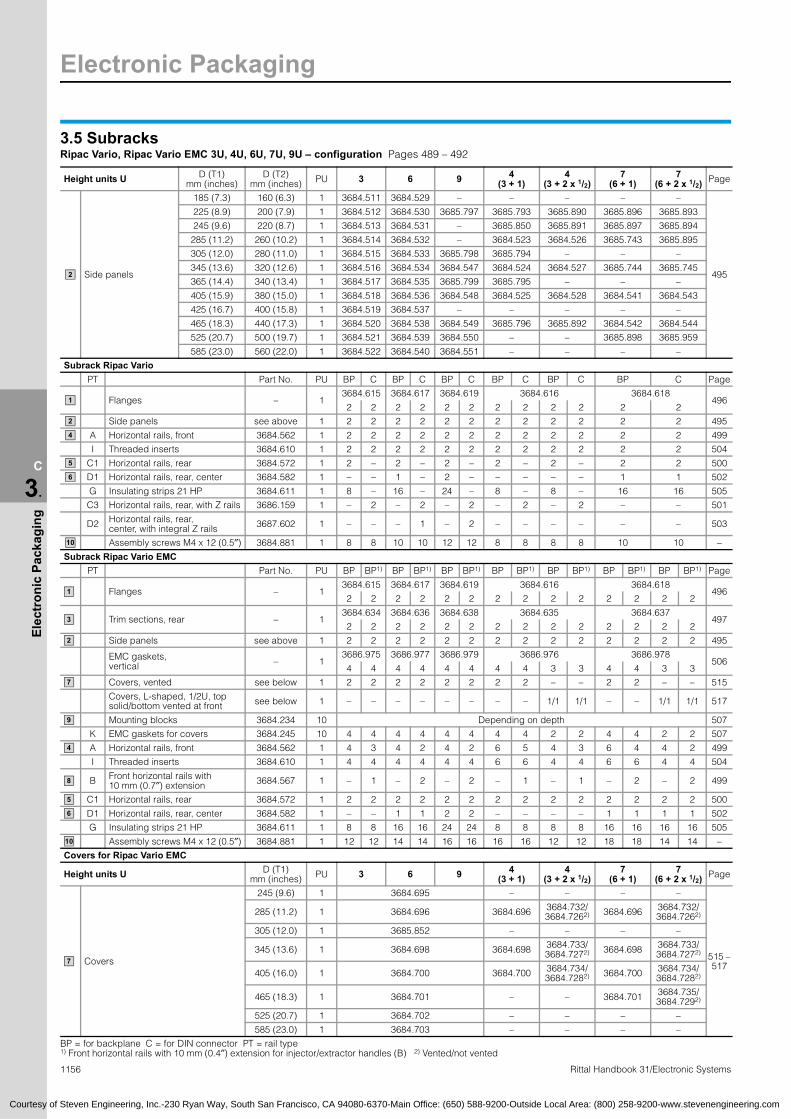
Electronic Packaging
1156 Rittal Handbook 31/Electronic Systems
C
3.
Elec
tron
ic P
acka
ging
3.5 SubracksRipac Vario, Ripac Vario EMC 3U, 4U, 6U, 7U, 9U – configuration Pages 489 – 492
Height units U D (T1)mm (inches)
D (T2)mm (inches) PU 3 6 9 4
(3 + 1)4
(3 + 2 x 1/2)7
(6 + 1)7
(6 + 2 x 1/2) Page
Side panels
185 (7.3) 160 (6.3) 1 3684.511 3684.529 – – – – –
495
225 (8.9) 200 (7.9) 1 3684.512 3684.530 3685.797 3685.793 3685.890 3685.896 3685.893
245 (9.6) 220 (8.7) 1 3684.513 3684.531 – 3685.850 3685.891 3685.897 3685.894
285 (11.2) 260 (10.2) 1 3684.514 3684.532 – 3684.523 3684.526 3685.743 3685.895
305 (12.0) 280 (11.0) 1 3684.515 3684.533 3685.798 3685.794 – – –
345 (13.6) 320 (12.6) 1 3684.516 3684.534 3684.547 3684.524 3684.527 3685.744 3685.745
365 (14.4) 340 (13.4) 1 3684.517 3684.535 3685.799 3685.795 – – –
405 (15.9) 380 (15.0) 1 3684.518 3684.536 3684.548 3684.525 3684.528 3684.541 3684.543
425 (16.7) 400 (15.8) 1 3684.519 3684.537 – – – – –
465 (18.3) 440 (17.3) 1 3684.520 3684.538 3684.549 3685.796 3685.892 3684.542 3684.544
525 (20.7) 500 (19.7) 1 3684.521 3684.539 3684.550 – – 3685.898 3685.959
585 (23.0) 560 (22.0) 1 3684.522 3684.540 3684.551 – – – –
Subrack Ripac VarioPT Part No. PU BP C BP C BP C BP C BP C BP C Page
Flanges – 13684.615 3684.617 3684.619 3684.616 3684.618
4962 2 2 2 2 2 2 2 2 2 2 2
Side panels see above 1 2 2 2 2 2 2 2 2 2 2 2 2 495
A Horizontal rails, front 3684.562 1 2 2 2 2 2 2 2 2 2 2 2 2 499
I Threaded inserts 3684.610 1 2 2 2 2 2 2 2 2 2 2 2 2 504
C1 Horizontal rails, rear 3684.572 1 2 – 2 – 2 – 2 – 2 – 2 2 500
D1 Horizontal rails, rear, center 3684.582 1 – – 1 – 2 – – – – – 1 1 502
G Insulating strips 21 HP 3684.611 1 8 – 16 – 24 – 8 – 8 – 16 16 505
C3 Horizontal rails, rear, with Z rails 3686.159 1 – 2 – 2 – 2 – 2 – 2 – – 501
D2 Horizontal rails, rear, center, with integral Z rails 3687.602 1 – – – 1 – 2 – – – – – – 503
Assembly screws M4 x 12 (0.5″) 3684.881 1 8 8 10 10 12 12 8 8 8 8 10 10 –
Subrack Ripac Vario EMCPT Part No. PU BP BP1) BP BP1) BP BP1) BP BP1) BP BP1) BP BP1) BP BP1) Page
Flanges – 13684.615 3684.617 3684.619 3684.616 3684.618
4962 2 2 2 2 2 2 2 2 2 2 2 2 2
Trim sections, rear – 13684.634 3684.636 3684.638 3684.635 3684.637
4972 2 2 2 2 2 2 2 2 2 2 2 2 2
Side panels see above 1 2 2 2 2 2 2 2 2 2 2 2 2 2 2 495
EMC gaskets, vertical – 1
3686.975 3686.977 3686.979 3686.976 3686.978506
4 4 4 4 4 4 4 4 3 3 4 4 3 3
Covers, vented see below 1 2 2 2 2 2 2 2 2 – – 2 2 – – 515
Covers, L-shaped, 1/2U, top solid/bottom vented at front see below 1 – – – – – – – – 1/1 1/1 – – 1/1 1/1 517
Mounting blocks 3684.234 10 Depending on depth 507
K EMC gaskets for covers 3684.245 10 4 4 4 4 4 4 4 4 2 2 4 4 2 2 507
A Horizontal rails, front 3684.562 1 4 3 4 2 4 2 6 5 4 3 6 4 4 2 499
I Threaded inserts 3684.610 1 4 4 4 4 4 4 6 6 4 4 6 6 4 4 504
B Front horizontal rails with 10 mm (0.7″) extension 3684.567 1 – 1 – 2 – 2 – 1 – 1 – 2 – 2 499
C1 Horizontal rails, rear 3684.572 1 2 2 2 2 2 2 2 2 2 2 2 2 2 2 500
D1 Horizontal rails, rear, center 3684.582 1 – – 1 1 2 2 – – – – 1 1 1 1 502
G Insulating strips 21 HP 3684.611 1 8 8 16 16 24 24 8 8 8 8 16 16 16 16 505
Assembly screws M4 x 12 (0.5″) 3684.881 1 12 12 14 14 16 16 16 16 12 12 18 18 14 14 –
Covers for Ripac Vario EMC
Height units U D (T1)mm (inches) PU 3 6 9 4
(3 + 1)4
(3 + 2 x 1/2)7
(6 + 1)7
(6 + 2 x 1/2) Page
Covers
245 (9.6) 1 3684.695 – – – –
515 – 517
285 (11.2) 1 3684.696 3684.696 3684.732/3684.7262) 3684.696 3684.732/
3684.7262)
305 (12.0) 1 3685.852 – – – –
345 (13.6) 1 3684.698 3684.698 3684.733/3684.7272) 3684.698 3684.733/
3684.7272)
405 (16.0) 1 3684.700 3684.700 3684.734/3684.7282) 3684.700 3684.734/
3684.7282)
465 (18.3) 1 3684.701 – – 3684.701 3684.735/3684.7292)
525 (20.7) 1 3684.702 – – – –
585 (23.0) 1 3684.703 – – – –
BP = for backplane C = for DIN connector PT = rail type 1) Front horizontal rails with 10 mm (0.4″) extension for injector/extractor handles (B) 2) Vented/not vented
2
1
2
4
5
6
10
1
3
2
7
9
4
8
5
6
10
7
Courtesy of Steven Engineering, Inc.-230 Ryan Way, South San Francisco, CA 94080-6370-Main Office: (650) 588-9200-Outside Local Area: (800) 258-9200-www.stevenengineering.com

Electronic Packaging
1157Rittal Handbook 31/Electronic Systems
C
3.
Elec
tron
ic P
acka
ging
251.64/144.96
190.
5
57.1
537
.43
57.1
5
213.64/106.96
269.64/162.96
2.75 2.75T1
T2
251.64/144.96
37.4
357
.15
213.64/106.96
269.64/162.96
T2
2.75 2.75T1
T1 2.752.75
T2
132
(3 H
E)
7.5 213.64/106.96
3.5 SubracksRipac Compact, 3U, 6U– configuration Page 493
EMC version Page
Height units U 3 3 3 3 6 3 3 3 3 6Horizontal pitch HP 21 21 42 42 42 21 21 42 42 42
D (T1)mm (inches)
D (T2)mm (inches) PU HS MP HS MP MP HS MP HS MP MP
Side panels225 (8.9) 200 (7.9) x 3684.512 3684.530 3684.512 3684.530
495 285 (11.2) 260 (10.2) x 3684.514 3684.532 3684.514 3684.532
PT Attachment PU For backplane
Side panels see above x 2 2 2 2 2 1 1 1 1 1 495
Side panels for cable entry x – – – – – 1 1 1 1 1 –
EMC PG cable gland x – – – – – 1 1 1 1 1 –
Trim sections, rear x 4 2 4 2 2 4 2 4 2 2 497
Flanges with keyhole x – 2 – 2 2 – 2 – 2 2 –
EMC front/rear panels x – – – – – – 1 – 1 1 –
EMC rear panel for rail adaptor x – – – – – 1 – 1 – – –
Rear panel for rail adaptor x 1 – 1 – – – – – – – –
Rail adaptor x 1 – 1 – – 1 – 1 – – –
EMC gaskets, vertical x – – – – – 3 3 3 3 3 506
Covers, vented see below x – – – – – 2 2 2 2 2 517
A Horizontal rails, front x 4 2 4 2 2 4 4 4 4 4 499
C1 Horizontal rails, rear x 2 2 2 2 2 2 2 2 2 2 500
I Threaded inserts x 4 2 4 2 2 4 4 4 4 4 504
G Insulating strips 21 HP x 2 2 4 4 8 2 2 4 4 8 505
D1 Horizontal rails, rear, center x – – – – 1 – – – – 1 502
Covers for Ripac CompactLP
mm (inches) PU 3 3 3 3 6 3 3 3 3 6 Page
Covers, vented 160 (6.3) 1 3687.624 3687.625 3687.6241) 3687.6251) 517
Covers, vented 220 (8.7) 1 3687.692 3687.677 3687.6921) 3687.6771) 517
F Z rails IEC 60 603-2 (DIN 41 612) 1 3684.599 3684.600 3684.599 3684.600 504
HS = top hat rail MP = mounting plate PT = rail type LP = PCB depth1) Included with the supply
2
2
3
1
7
4
5
6
7
For top hat rail For mounting plate
132
(3 H
E) 26
5.35
(6 H
E)
HE = U
Courtesy of Steven Engineering, Inc.-230 Ryan Way, South San Francisco, CA 94080-6370-Main Office: (650) 588-9200-Outside Local Area: (800) 258-9200-www.stevenengineering.com

Electronic Packaging
1158 Rittal Handbook 31/Electronic Systems
C
3.
Elec
tron
ic P
acka
ging
124
12.5
12.5
124
124
T2
T1
4.1
T1
T2
4.1
482.6 (19˝)
482.6 (19˝)
132
265.
35
3.5 SubracksRipac Vario Mobil 3U, 6U – configuration Page 494
EMC EMC Page
Height units U 3 3 3 6 6 6D (T1)
mm (inches)D (T2)
mm (inches) PU BP C BP BP C BP
Side panels 245 (9.6) 220 (8.7) 1 3684.513 3684.531 495
PT Part no. PU
Flanges – 13684.615 3684.617
496 2 2 2 2 2 2
Trim sections, rear – 1 – –2
– –2
497 3684.634 3684.636
Side panels see above 1 2 2 2 2 2 2 495
EMC gaskets, vertical – 1 – –2
– –2
506 3686.975 3686.977
Covers, vented 3684.695 1 – – 2 – – 2 515
Mounting blocks 3684.234 10 – – 20 (0.8) – – 20 (0.8) 507
K EMC gaskets for covers 3684.245 10 – – 4 – – 4 507
A Horizontal rails, front 3684.562 1 4 4 4 4 4 4 499
I Threaded inserts 3684.610 1 4 4 4 4 4 4 504
C1 Horizontal rails, rear 3684.572 1 2 – 2 2 – 2 500
D1 Horizontal rails, rear, center 3684.582 1 – – 1 – 1 502
G Insulating strips 21 HP 3684.611 1 8 – 8 16 – 16 505
C3 Horizontal rails, rear, with integral Z rails 3686.159 1 – 2 – – 2 – 501
D2 Horizontal rails, rear, center, with integral Z rails 3687.602 1 – – – 1 – 503
Assembly screws M4 x 12 (0.5″) 3684.881 1 12 12 12 14 14 14 –
Assembly screws M3 x 6 (0.3″) 3684.883 1 – – 60 – – 60 –
BP = for backplane C = for DIN connector PT = rail type
2
1
3
2
7
9
4
5
63U
6U
84 HP
84 HP
Courtesy of Steven Engineering, Inc.-230 Ryan Way, South San Francisco, CA 94080-6370-Main Office: (650) 588-9200-Outside Local Area: (800) 258-9200-www.stevenengineering.com
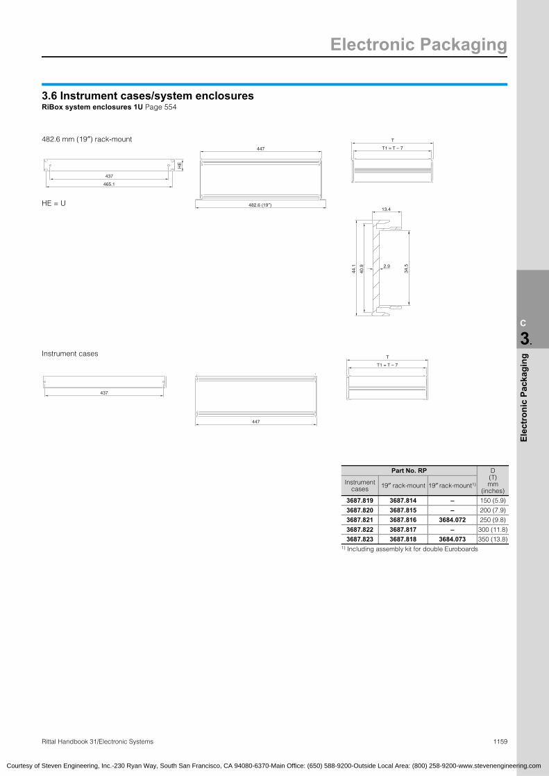
Electronic Packaging
1159Rittal Handbook 31/Electronic Systems
C
3.
Elec
tron
ic P
acka
ging
437
465.1
T
482.6 (19″)
T1 = T – 7
34.52.9
40.9
44.1
13.4
HE
437
447
T
T1 = T – 7
Part No. RP D(T) mm
(inches)Instrument
cases 19″ rack-mount 19″ rack-mount1)
3687.819 3687.814 – 150 (5.9)
3687.820 3687.815 – 200 (7.9)
3687.821 3687.816 3684.072 250 (9.8)
3687.822 3687.817 – 300 (11.8)
3687.823 3687.818 3684.073 350 (13.8)1) Including assembly kit for double Euroboards
HE = U
Courtesy of Steven Engineering, Inc.-230 Ryan Way, South San Francisco, CA 94080-6370-Main Office: (650) 588-9200-Outside Local Area: (800) 258-9200-www.stevenengineering.com
3.6 Instrument cases/system enclosuresRiBox system enclosures 1U Page 554
447
482.6 mm (19″) rack-mount
Instrument cases

Electronic Packaging
1160 Rittal Handbook 31/Electronic Systems
C
3.
Elec
tron
ic P
acka
ging
122.
45
e x 10 = f
3 H
E
132.
5
57.1
5
TE
168.
5
122.
45
33.6
5
e x 10 = f
300.
4
122.
4512
2.45
33.6
5
e x 10 = f
7 H
E
310.
4
57.1
588
.988
.9
248
TE
122.
4512
2.45
255.
9
e x 10 = f
4 H
E
17711
4.5
101.
6
TE
6 H
E
265.
9
248
190.
5
TE
Courtesy of Steven Engineering, Inc.-230 Ryan Way, South San Francisco, CA 94080-6370-Main Office: (650) 588-9200-Outside Local Area: (800) 258-9200-www.stevenengineering.com
3.6 Instrument cases/system enclosuresRipac Vario-Module Pages 555 – 558
Part No. VM
U (HE)
HP(TE)
D (T) mm
(inches)e
W (B1)mm
(inches)
W (B2)mm
(inches)
3982.040 3 42 250.4(9.9) 22 235.6
(9.3)251.6(9.9)
3982.070 3 42 310.4(12.2) 28 235.6
(9.3)251.6(9.9)
3982.050 3 63 250.4 (9.9) 22 342.3
(13.5)358.3 (14.1)
3982.080 3 63 310.4 (12.2) 28 342.3
(13.5)358.3 (14.1)
3982.060 3 84 250.4 (9.9) 22 449.0
(17.7)465.1 (18.3)
3982.090 3 84 310.4 (12.2) 28 449.0
(17.7)465.1 (18.3)
3982.100 3 84 370.4 (14.6) 34 449.0
(17.7)465.1 (18.3)
3982.110 4 84 250.4 (9.9) 22 449.0
(17.7)465.1 (18.3)
3982.120 4 84 310.4 (12.2) 28 449.0
(17.7)465.1 (18.3)
3982.130 4 84 370.4 (14.6) 34 449.0
(17.7)465.1 (18.3)
3982.140 6 84 310.4 (12.2) 28 449.0
(17.7)465.1 (18.3)
3982.150 6 84 370.4 (14.6) 34 449.0
(17.7)465.1 (18.3)
3982.160 6 84 430.4 (16.9) 40 449.0
(17.7)465.1 (18.3)
3982.170 7 84 310.4 (12.2) 28 449.0
(17.7)465.1 (18.3)
3982.190 7 84 430.4 (16.9) 40 449.0
(17.7)465.1 (18.3)
Part No. VM
(EMC)U
(HE)HP (TE)
D (T) mm
(inches)e
W (B1)mm
(inches)
W (B2)mm
(inches)
3983.040 3 42 250.4 (9.9) 22 235.6
(9.3)251.6 (9.9)
3983.070 3 42 310.4 (12.2) 28 235.6
(9.3)251.6 (9.9)
3983.050 3 63 250.4 (9.9) 22 342.3
(13.5)358.3 (14.1)
3983.080 3 63 310.4 (12.2) 28 342.3
(13.5)358.3 (14.1)
3983.060 3 84 250.4 (9.9) 22 449.0
(17.7)465.1 (18.3)
3983.090 3 84 310.4 (12.2) 28 449.0
(17.7)465.1 (18.3)
3983.100 3 84 370.4 (14.6) 34 449.0
(17.7)465.1 (18.3)
3983.110 4 84 250.4 (9.9) 22 449.0
(17.7)465.1 (18.3)
3983.120 4 84 310.4 (12.2) 28 449.0
(17.7)465.1 (18.3)
3983.130 4 84 370.4 (14.6) 34 449.0
(17.7)465.1 (18.3)
3983.140 6 84 310.4 (12.2) 28 449.0
(17.7)465.1 (18.3)
3983.150 6 84 370.4 (14.6) 34 449.0
(17.7)465.1 (18.3)
3983.160 6 84 430.4 (16.9) 40 449.0
(17.7)465.1 (18.3)
3983.170 7 84 310.4 (12.2) 28 449.0
(17.7)465.1 (18.3)
3983.190 7 84 430.4 (16.9) 40 449.0
(17.7)465.1 (18.3)
T B1
B2
3U
T B1
B2
4U
T B1
B2
6U
T B1
B2
7U

Electronic Packaging
C
3.
Elec
tron
ic P
acka
ging
Ba
b
c
HEH
9.5
6.3
31.7
5
44.4
5 12.7
B
A
B
HE
(H
1)
T
5050
63.5
120
100
d x
120
40
30
67.5
12.5
30
7.5
353
5
3.6 Instrument cases/system enclosuresRittal RiCase 269.2 mm (1/2 19″) Page 562
Rittal RiCase 482.6 mm (19″) Page 563
Detail X
Section B – B
HE = U
Courtesy of Steven Engineering, Inc.-230 Ryan Way, South San Francisco, CA 94080-6370-Main Office: (650) 588-9200-Outside Local Area: (800) 258-9200-www.stevenengineering.com
XRittal RiCase 269.2 mm (1/2 19″) – in RAL colors: RAL 5018 (teal), RAL 5012 (light blue), RAL 7030 (stone gray)
Not ventedPart No. RC, RAL 5018 3750.100 – 3750.200 – 3750.210 3750.300 – 3750.400 –
Part No. RC, RAL 5012 3750.102 – 3750.202 – 3750.212 3750.302 – 3750.402 –
Part No. RC, RAL 7030 3750.104 – 3750.204 – 3750.214 3750.304 – 3750.404 –
VentedPart No. RC, RAL 5018 – 3750.110 – 3750.220 – 3750.350 3750.360 – 3750.450
Part No. RC, RAL 5012 – 3750.112 – 3750.222 – 3750.352 3750.362 – 3750.452
Part No. RC, RAL 7030 – 3750.114 – 3750.224 – 3750.354 3750.364 – 3750.454
U 1 2 3 4
Height (H) in mm (inches) 77.5 (3.1) 77.5 (3.1) 121.9 (4.8) 121.9 (4.8) 166.4 (6.6) 166.4 (6.6) 166.4 (6.6) 210.8 (8.3) 210.8 (8.3)
H1 (HE) in mm (inches) 45.0 (1.8) 45.0 (1.8) 89.4 (3.5) 89.4 (3.5) 133.8 (5.3) 133.8 (5.3) 133.8 (5.3) 178.3 (7.0) 178.3 (7.0)
Width (B) in mm (inches) 348.6 (13.7) 348.6 (13.7) 348.6 (13.7) 348.6 (13.7) 348.6 (13.7) 348.6 (13.7) 348.6 (13.7) 348.6 (13.7) 348.6 (13.7)
Depth (T) in mm (inches) 300.0 (11.8) 420.0 (16.5) 300.0 (11.8) 540.0 (21.3) 300.0 (11.8) 420.0 (16.5) 540.0 (21.3) 420.0 (16.5) 540.0 (21.3)
a in mm (inches) 280.6 (11.0) 280.6 (11.0) 280.6 (11.0) 280.6 (11.0) 280.6 (11.0) 280.6 (11.0) 280.6 (11.0) 280.6 (11.0) 280.6 (11.0)
b in mm (inches) 251.6 (9.9) 251.6 (9.9) 251.6 (9.9) 251.6 (9.9) 251.6 (9.9) 251.6 (9.9) 251.6 (9.9) 251.6 (9.9) 251.6 (9.9)
c in mm (inches) 237.2 (9.3) 237.2 (9.3) 237.2 (9.3) 237.2 (9.3) 237.2 (9.3) 237.2 (9.3) 237.2 (9.3) 237.2 (9.3) 237.2 (9.3)
d in mm (inches) – 1 – 2 – 1 2 1 2
1161Rittal Handbook 31/Electronic Systems
Rittal RiCase 482.6 mm (19″) – in RAL colors: RAL 5018 (teal), RAL 5012 (light blue), RAL 7030 (stone gray)
Not ventedPart No. RC, RAL 5018 3750.310 3750.320 3750.410 3750.420 3750.600 3750.610 3750.620 3750.700 3750.710 3750.900 3750.910 3750.000
Part No. RC, RAL 5012 3750.312 3750.322 3750.412 3750.422 3750.602 3750.612 3750.622 3750.702 3750.712 3750.902 3750.912 3750.002
Part No. RC, RAL 7030 3750.314 3750.324 3750.414 3750.424 3750.604 3750.614 3750.624 3750.704 3750.714 3750.904 3750.914 3750.004
VentedPart No. RC, RAL 5018 3750.330 3750.340 3750.430 3750.440 3750.630 3750.640 3750.650 3750.720 3750.730 3750.920 3750.930 3750.030
Part No. RC, RAL 5012 3750.332 3750.342 3750.432 3750.442 3750.632 3750.642 3750.652 3750.722 3750.732 3750.922 3750.932 3750.032
Part No. RC, RAL 7030 3750.334 3750.344 3750.434 3750.444 3750.634 3750.644 3750.654 3750.724 3750.734 3750.924 3750.934 3750.034
U 3 4 6 7 9 12
Height (H) in mm (inches) 166.4 (6.6) 166.4 (6.6) 210.8 (8.3) 210.8 (8.3) 299.7 (11.8) 299.7 (11.8) 299.7 (11.8) 344.2 (13.6) 344.2 (13.6) 433.1 (17.1) 433.1 (17.1) 566.5 (22.3)
H1 (HE) in mm (inches) 133.8 (5.3) 133.8 (5.3) 178.3 (7.0) 178.3 (7.0) 267.2 (10.5) 267.2 (10.5) 267.2 (10.5) 311.7 (12.3) 311.7 (12.3) 400.6 (15.8) 400.6 (15.8) 534.0 (21.0)
Width (B) in mm (inches) 562.0 (22.1) 562.0 (22.1) 562.0 (22.1) 562.0 (22.1) 562.0 (22.1) 562.0 (22.1) 562.0 (22.1) 562.0 (22.1) 562.0 (22.1) 562.0 (22.1) 562.0 (22.1) 562.0 (22.1)
Depth (T) in mm (inches) 300.0 (11.8) 420.0 (16.5) 300.0 (11.8) 420.0 (16.5) 300.0 (11.8) 420.0 (16.5) 540.0 (21.3) 420.0 (16.5) 540.0 (21.3) 420.0 (16.5) 540.0 (21.3) 540.0 (21.3)
a in mm (inches) 494.0 (19.4) 494.0 (19.4) 494.0 (19.4) 494.0 (19.4) 494.0 (19.4) 494.0 (19.4) 494.0 (19.4) 494.0 (19.4) 494.0 (19.4) 494.0 (19.4) 494.0 (19.4) 494.0 (19.4)
b in mm (inches) 465.0 (18.3) 465.0 (18.3) 465.0 (18.3) 465.0 (18.3) 465.0 (18.3) 465.0 (18.3) 465.0 (18.3) 465.0 (18.3) 465.0 (18.3) 465.0 (18.3) 465.0 (18.3) 465.0 (18.3)
c in mm (inches) 450.6 (17.7) 450.6 (17.7) 450.6 (17.7) 450.6 (17.7) 450.6 (17.7) 450.6 (17.7) 450.6 (17.7) 450.6 (17.7) 450.6 (17.7) 450.6 (17.7) 450.6 (17.7) 450.6 (17.7)
d in mm (inches) – 1 – 1 – 1 2 1 2 1 2 2

Electronic Packaging
1162 Rittal Handbook 31/Electronic Systems
C
3.
Elec
tron
ic P
acka
ging
A
44.4
5
12.
7
31.7
5
6.5
HEH
251.5
295.5
270.5
320.5
236.5
9.5 A
320.5
3
251.5
269.3
295.5
12.
5
12.
5
k x
12.5
= I
dY
Z
B
B
f x 2
5 =
g 5
0
T
h x
12.5
= i
62.
5 6
2.5
236.5
251.5
12.
5
50
3
R 3
320.5
295.5
270.5
6.25
62.
5
15
18.75
3.6 Instrument cases/system enclosuresRittal Vario-Case iS 269.2 mm (1/2 19″) Page 569
Part No. VC without vent slots 3710.000 3720.000 3730.000 3731.000 3740.000 3741.000
U 1 2 3 4
Height (H) in mm (inches) 74.75 (2.9) 119.20 (4.7) 163.65 (6.4) 163.65 (6.4) 208.10 (8.2) 208.10 (8.2)
Depth (T) in mm (inches) 300 (11.8) 300 (11.8) 300 (11.8) 400 (15.7) 300 (11.8) 400 (15.7)
d in mm (inches) 64.75 (2.5) 109.20 (4.3) 153.65 (6.0) 153.65 (6.0) 198.10 (7.8) 198.10 (7.8)
f in mm (inches) 8 (0.3) 8 (0.3) 8 (0.3) 12 (0.5) 8 (0.3) 12 (0.5)
g in mm (inches) 200 (7.9) 200 (7.9) 200 (7.9) 300 (11.8) 200 (7.9) 300 (11.8)
h in mm (inches) 20 (0.8) 20 (0.8) 20 (0.8) 28 (1.1) 20 (0.8) 28 (1.1)
i in mm (inches) 250 (9.7) 250 (9.7) 250 (9.7) 350 (9.8) 250 (9.7) 350 (9.8)
k in mm (inches) 22 (0.9) 22 (0.9) 22 (0.9) 30 (1.2) 22 (0.9) 30 (1.2)
l in mm (inches) 275 (10.8) 275 (10.8) 275 (10.8) 375 (14.8) 275 (10.8) 375 (14.8)
Detail YSection A – A
Section B – B
Detail Z
HE = U
Courtesy of Steven Engineering, Inc.-230 Ryan Way, South San Francisco, CA 94080-6370-Main Office: (650) 588-9200-Outside Local Area: (800) 258-9200-www.stevenengineering.com
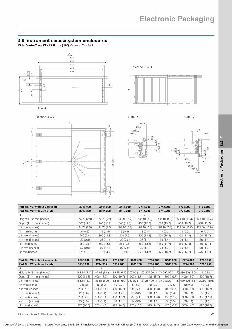
Electronic Packaging
1163Rittal Handbook 31/Electronic Systems
C
3.
Elec
tron
ic P
acka
ging
A
A
450
465
509
484
534
9.
5
44.4
5HEH
12.
7
31.7
5
6.5
d
f x 2
5 =
g
T
50
Z
62.
5
h x
12.5
= i
62.
5
XB
B
3.6 Instrument cases/system enclosuresRittal Vario-Case iS 482.6 mm (19″) Pages 570 – 571.
Part No. VC without vent slots 3713.000 3714.000 3743.000 3744.000 3745.000 3774.000 3775.000
Part No. VC with vent slots 3713.200 3714.200 3743.200 3744.200 3745.200 3774.200 3775.200
U 1 4 7
Height (H) in mm (inches) 74.75 (2.9) 74.75 (2.9) 208.10 (8.2) 208.10 (8.2) 208.10 (8.2) 341.40 (13.4) 341.40 (13.4)
Depth (T) in mm (inches) 300 (11.8) 400 (15.7) 300 (11.8) 400 (15.7) 500 (19.7) 400 (15.7) 500 (19.7)
d in mm (inches) 64.75 (2.5) 64.75 (2.5) 198.10 (7.8) 198.10 (7.8) 198.10 (7.8) 331.40 (13.0) 331.40 (13.0)
f in mm (inches) 8 (0.3) 12 (0.5) 8 (0.3) 12 (0.5) 16 (0.6) 12 (0.5) 16 (0.6)
g in mm (inches) 200 (7.9) 300 (11.8) 200 (7.9) 300 (11.8) 400 (15.7) 300 (11.8) 400 (15.7)
h in mm (inches) 20 (0.8) 28 (1.1) 20 (0.8) 28 (1.1) 36 (1.4) 28 (1.1) 36 (1.4)
i in mm (inches) 250 (9.8) 350 (13.8) 250 (9.8) 350 (13.8) 450 (17.7) 350 (13.8) 450 (17.7)
k in mm (inches) 22 (0.9) 30 (1.1) 22 (0.9) 30 (1.1) 38 (1.5) 30 (1.1) 38 (1.5)
l in mm (inches) 275 (10.8) 375 (14.7) 275 (10.8) 375 (14.7) 475 (18.7) 375 (14.7) 475 (18.7)
Section B – B
Detail Z
320.5
3
251.5
269.3
295.5
12.
5
12.
5
k x
12.5
= I
236.5
251.5
12.
5
50
3
R 3
320.5
295.5
270.5
6.25
62.
5
15
18.75
Section A – A Detail Y
Part No. VC without vent slots 3733.000 3734.000 3735.000 3763.000 3764.000 3765.000 3794.000 3795.000
Part No. VC with vent slots 3733.200 3734.200 3735.200 3763.200 3764.200 3765.200 3794.200 3795.200
U 3 6 9
Height (H) in mm (inches) 163.65 (6.4) 163.65 (6.4) 163.65 (6.4) 297.00 (11.7) 297.00 (11.7) 297.00 (11.7) 430.50 (16.9) 430.50
Depth (T) in mm (inches) 300 (11.8) 400 (15.7) 500 (19.7) 300 (11.8) 400 (15.7) 500 (19.7) 400 (15.7) 500 (19.7)
d in mm (inches) 153.65 (6.0) 153.65 (6.0) 153.65 (6.0) 287.00 (11.3) 287.00 (11.3) 287.00 (11.3) 420.50 (16.6) 420.50 (16.6)
f in mm (inches) 8 (0.3) 12 (0.5) 16 (0.6) 8 (0.3) 12 (0.5) 16 (0.6) 12 (0.5) 16 (0.6)
g in mm (inches) 200 (7.9) 300 (11.8) 400 (15.7) 200 (7.9) 300 (11.8) 400 (15.7) 300 (11.8) 400 (15.7)
h in mm (inches) 20 (0.8) 28 (1.1) 36 (1.4) 20 (0.8) 28 (1.1) 36 (1.4) 28 (1.1) 36 (1.4)
i in mm (inches) 250 (9.8) 350 (13.8) 450 (17.7) 250 (9.8) 350 (13.8) 450 (17.7) 350 (13.8) 450 (17.7)
k in mm (inches) 22 (0.9) 30 (1.1) 38 (1.5) 22 (0.9) 30 (1.1) 38 (1.5) 30 (1.1) 38 (1.5)
l in mm (inches) 275 (10.8) 375 (14.7) 475 (18.7) 275 (10.8) 375 (14.7) 475 (18.7) 375 (14.7) 475 (18.7)
HE = U
Courtesy of Steven Engineering, Inc.-230 Ryan Way, South San Francisco, CA 94080-6370-Main Office: (650) 588-9200-Outside Local Area: (800) 258-9200-www.stevenengineering.com

Climate ControlClimate controlled enclosures
1164 Rittal Handbook 31/Climate Control Systems
C
4.
Clim
ate
Con
trol
605
157
461
0
31
1
1800
(20
00)
797
min
. 100
157
605
661
0
31
1
1800
(20
00)
597
min
. 100
461
80
T2
1800
/200
0
1197
T1
1197
1800
/200
0
461
80
T2
T1
900
250
686.5
Courtesy of Steven Engineering, Inc.-230 Ryan Way, South San Francisco, CA 94080-6370-Main Office: (650) 588-9200-Outside Local Area: (800) 258-9200-www.stevenengineering.com
4.1 Climate controlled enclosuresSingle-door, useful cooling capacity 1100/1500 W (3756/5123 BTU) Page 582
1100 W (3756 BTU) 1500 W (5123 BTU)
8512
max. installation depth = 478 mm (18.8″)
1
8712
max. installation depth = 478 mm (18.8″)
1
Two-door, useful cooling capacity 2000/2500 W (6830/8538 BTU) Page 583
Device positionleft
Device positionright
min
.100
min
.100
2000 W (6830 BTU) 2500 W (8538 BTU)
D (T1) max. 445 mm (17.5″) 415 mm (16.3″)
D (T2) 190 mm (7.5″) 220 mm (8.7″)

Climate control doors
Climate Control
1165Rittal Handbook 31/Climate Control Systems
C
4.
Clim
ate
Con
trol
1777
.5 (
1977
.5)
592
1777
.5 (
1977
.5)
592
190
90
461
480
80
157
57
461
592
1777
.5 (
1977
.5)
1777
.5 (
1977
.5)
592
900
250
190
90
461
220
120461
For installing in 800 mm (31.5″) wide TS8 modular enclosures, useful cooling capacity 1500 W (5123 BTU) Page 585
480
80
157
57
661
1777
.5 (
1977
.5)
792
592
1777
.5 (
1977
.5)
1777
.5 (
1977
.5)
592
900
25017
77.5
(19
77.5
)
592
220
120461
190
90
461
1777
.5 (
1977
.5)
592
157
57
461
190
90
461
Courtesy of Steven Engineering, Inc.-230 Ryan Way, South San Francisco, CA 94080-6370-Main Office: (650) 588-9200-Outside Local Area: (800) 258-9200-www.stevenengineering.com
4.1 Climate control doorsFor installing in 600 mm (23.6″) wide TS8 modular enclosures, useful cooling capacity 1100/1500 W (3756/5123 BTU) Page 584
For installing in 600 mm (23.6″) wide TS8 modular enclosures, useful cooling capacity 2000/2500 W (6830/8538 BTU) Page 586
1100 W (3756 BTU) 1500 W (5123 BTU) 2000 W (6830 BTU) 2500 W (8538 BTU)
For installing in 1200 mm (47.2″) wide TS8 modular enclosures, useful cooling capacity 1100/1500 W (3756/5123 BTU) Page 587
For installing in 1200 mm (47.2″) wide TS8 modular enclosures, useful cooling capacity 2000/2500 W (6830/8538 BTU) Page 588
1100 W (3756 BTU) 1500 W (5123 BTU) 2000 W (6830 BTU) 2500 W (8538 BTU)

Climate ControlRoof-mounted air conditioners
1166 Rittal Handbook 31/Climate Control Systems
C
4.
Clim
ate
Con
trol
597
415
365
Ø 80
30
1
375
415
326
1701
475
260
326
375
597
597
415
380
Ø 100 27
1
475
415
420
2801
490
597
420
390
475
470
796
538
Ø 150
38.5
1
580
238
Ø 150
1580 52
0
392
796
692
Courtesy of Steven Engineering, Inc.-230 Ryan Way, South San Francisco, CA 94080-6370-Main Office: (650) 588-9200-Outside Local Area: (800) 258-9200-www.stevenengineering.com
4.1 Roof-mounted air conditionersUseful cooling capacity 500/750 W (1708/2561 BTU) Page 590
Mounting cutout
Condensate discharge 1/2″, flexible1
Useful cooling capacity 1000 W (3415 BTU) Page 591
Useful cooling capacity 1100 W (3756 BTU) Page 592
Useful cooling capacity 1500/2000 W (5123/6830 BTU) Page 593
Mounting cutout
Condensate discharge 1/2″, flexible1
Useful cooling capacity 3000/4000 W (10,246/13,661 BTU) Page 594
Mounting cutout
Condensate discharge 1/2″, flexible1

Wall-mounted air conditioners
Climate Control
1167
C
4.
Clim
ate
Con
trol
6
340
27
281
471
525
499
(483)
9
30°
10517
525
4
25
25
Ø 7 (4x)
340
333
4 9
17
314
525
340
15355
280
550
140 42
550
501
251
18 x 45°(230)
200
524
Ø 8 (4x)
Ø 15 (2x)
266
2549
2
518
550
280
550
T1 T
T5
T4
262
266
480
15.5
550
Ø 8 (4x)
532
200
18 x 45°
Ø 8 (4x)
(230)
524 266 49
225
518
550
Ø 19 (2x)
254
266
18 x 45°
Ø 8 (4x)
(230)
524 49
225
518
550
Courtesy of Steven Engineering, Inc.-230 Ryan Way, South San Francisco, CA 94080-6370-Main Office: (650) 588-9200-Outside Local Area: (800) 258-9200-www.stevenengineering.com
4.1 Wall-mounted air conditionersMini in horizontal format, useful cooling capacity 300 W (1025 BTU) Page 596
Mounting cutoutexternal mounting
Mounting cutoutinternal mounting
External mounting
Internal mounting
98
98
Useful cooling capacity 300 W (1025 BTU) Page 597
280
Mounting cutoutexternal mounting
Mounting cutoutinternal mounting
Internal mounting
External mounting
280
254Useful cooling capacity 500 W (1708 BTU) Page 597
Useful cooling capacity 750 W (2561 BTU) Page 598
Partial internal
External mounting
Internal mounting
Mounting cutoutexternal mounting
Mounting cutoutpartial internal
Mounting cutoutinternal mounting
T3
2
mounting
280
mo
280
unting
254
280
Rittal Handbook 31/Climate Control Systems
D (T1) D (T2) D (T3) D (T4) D (T5)
500 W(1708 BTU)
200 mm(7.9″)
100 mm(3.9″)
100 mm(3.9″)
158 mm(6.2″)
42 mm(1.7″)
750 W(2561 BTU)
280 mm(11.0″)
125 mm(4.9″)
155 mm(6.1″)
235 mm(9.3″)
45 mm(1.8″)

Climate ControlWall-mounted air conditioners
1168 Rittal Handbook 31/Climate Control Systems
C
4.
Clim
ate
Con
trol
950
400 260 210 370
330
Ø 9.5 (4x)
380950
920
920
25 x 45°
380
Ø 9.5 (4x)
370
R6 (4x) 25
920
920
950
2
25 x
45°
400
345
280
235
255
950
15
350
25
Ø
385
1580
400 50145290
370
320
320
Ø 13 (4x)
1558
1554
1540
1580
Ø 9.5 (2x)
25
Ø 9.5 (2x)
376
280
350
Ø 13 (10x)
400
3529
5
380
1580
260
2555
0
320
275
340
325
500
1580
145 195
153015
50
25
474
Ø 13 (4x)
1580
500
380
440
440
Ø 13 (10x)
4533
0
1580
164
360
380
500
375
380
275
25
Courtesy of Steven Engineering, Inc.-230 Ryan Way, South San Francisco, CA 94080-6370-Main Office: (650) 588-9200-Outside Local Area: (800) 258-9200-www.stevenengineering.com
4.1 Wall-mounted air conditionersUseful cooling capacity 1500/2000 W (5123/6830 BTU) Page 599
Mounting cutout Mounting cutoutMounting cutoutExternal Internal Partial
mounting im
mnternalounting155105
ounting
50
external mounting pm
inteartial internal ounting
400
rnal mounting
400
Useful cooling capacity 1500/2000 W (5123/6830 BTU) Page 600
External mounting
145
Inm
Partial internal mounting
240
ternal ounting1)
Mounting cutoutexternal mounting
Mounting cutoutpartial internal mounting, internal mounting
400
1) For installation in 600 mm (23.6″) wide doors, move the mounting cutout from the center of the door to the hinged side by at least 10 mm (0.4″).
Useful cooling capacity 4000 W (13,661 BTU) Page 601
340
External mounting
Partial internal mounting
Mounting cutoutexternal mounting
Mounting cutoutpartial internal mounting
500
362
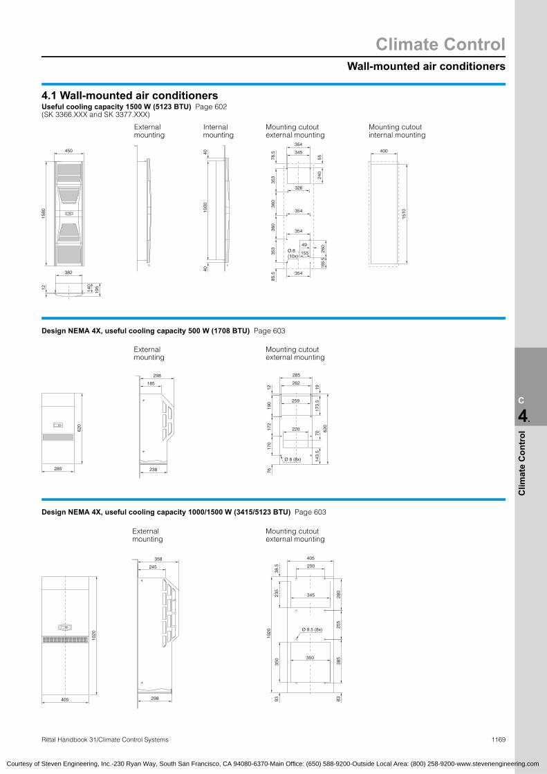
Wall-mounted air conditioners
Climate Control
1169Rittal Handbook 31/Climate Control Systems
C
4.
Clim
ate
Con
trol
450
1580
382
12 140
195
4040
1500
Ø 8 (10x)
155
345
326
354
240
5526
016
5.5
353
360
85.5
360
353
78.5
354
354
49
1510
400
285
620
238
298
185
285
262
1219
017
217
076
1917
3.5259
220
7014
3.5
620
Ø 8 (8x)
405
1020
358
245
298
38.5
235
1020
350
93
350
Ø 9.5 (8x)
8338
525
5
345 280
250
Courtesy of Steven Engineering, Inc.-230 Ryan Way, South San Francisco, CA 94080-6370-Main Office: (650) 588-9200-Outside Local Area: (800) 258-9200-www.stevenengineering.com
4.1 Wall-mounted air conditionersUseful cooling capacity 1500 W (5123 BTU) Page 602 (SK 3366.XXX and SK 3377.XXX)
Mounting cutoutexternal mounting
Mounting cutoutinternal mounting
Internal mounting
External mounting
354
Design NEMA 4X, useful cooling capacity 500 W (1708 BTU) Page 603
External mounting
Mounting cutoutexternal mounting
Design NEMA 4X, useful cooling capacity 1000/1500 W (3415/5123 BTU) Page 603
External Mounting cutout
mounting405
external mounting

Climate ControlWall-mounted air conditioners
1170 Rittal Handbook 31/Climate Control Systems
C
4.
Clim
ate
Con
trol
405
1650
388
275
328
3729
5
1650
260
408
320
Ø 13 (10x)
550
380
405
280
350
9327
532
5
Courtesy of Steven Engineering, Inc.-230 Ryan Way, South San Francisco, CA 94080-6370-Main Office: (650) 588-9200-Outside Local Area: (800) 258-9200-www.stevenengineering.com
4.1 Wall-mounted air conditionersDesign NEMA 4X, useful cooling capacity 2000/2500 W (6830/8538 BTU) Page 604
External mounting Mounting cutout
external mounting
Chillers
Climate Control
1171Rittal Handbook 31/Climate Control Systems
C
4.
Clim
ate
Con
trol
4.2 Options for chillers
Pre
ssur
e-se
aled
sys
tem
Op
en s
yste
m w
ith ta
nk
Des
igne
d a
s a
once
-thr
oug
h co
oler
with
out t
ank
Hot
gas
byp
ass
cont
rol i
n th
e co
olin
g c
ircui
t
Mor
e p
ower
ful p
ump
(s)
Hea
ter
in th
e ta
nk (
1000
W)
Wat
er le
vel s
witc
h
Flow
mon
itor
Wat
er fi
lter/
oil f
ilter
Wat
er-c
oole
d c
ond
ense
r
Up
stre
am p
ipew
ork,
free
from
non
-fer
rous
met
als
Aut
omat
ic ta
nk fi
lling
Faul
t sig
nal w
ith in
div
idua
l mes
sag
es
Am
bie
nt te
mp
erat
ure
cont
rol
Aut
omat
ic b
ypas
s
Man
ual b
ypas
s
Har
ting
con
nect
or
Out
doo
r si
ting
Sp
ecia
l sp
ray
finis
h
Sp
ecia
l vol
tag
e
Met
al fi
lter
mat
Cas
tors
Ref
riger
ant R
134a
Dou
ble
pum
p u
nit
Filte
r m
at m
onito
ring
Bas
e tr
ay
Tank
(st
ainl
ess
stee
l 1.4
301)
Ad
diti
onal
med
ium
con
nect
ions
Chillers mini and mini for wall-mountingSK 3318.600 � – � – ▫ – – � – ▫ ▫ – – ▫ – ▫ ▫ ▫ ▫ ▫ ▫ ▫ � – � – – –
SK 3318.610 – � – – ▫ – – � – ▫ ▫ – – ▫ – ▫ ▫ ▫ ▫ ▫ ▫ ▫ � – � – – –
SK 3319.600 � – � – ▫ – – � – ▫ ▫ – – ▫ – ▫ ▫ ▫ ▫ ▫ ▫ ▫ � – � – – –
SK 3319.610 – � – – ▫ – – � – ▫ ▫ – – ▫ – ▫ ▫ ▫ ▫ ▫ ▫ ▫ � – � – – –
SK 3320.600 – � – ▫ ▫ ▫ ▫ � – ▫ ▫ – – ▫ ▫ ▫ ▫ ▫ ▫ ▫ ▫ ▫ � – � – � –
SK 3334.600 – � – ▫ ▫ ▫ ▫ � – ▫ ▫ – – ▫ ▫ ▫ ▫ ▫ ▫ ▫ ▫ ▫ � – � – � –
SK 3360.100 – � – ▫ ▫ – ▫ � – ▫ ▫ – – ▫ – ▫ ▫ – ▫ ▫ ▫ – � – � – – –
SK 3360.250 – � – ▫ ▫ – ▫ � – ▫ ▫ – – ▫ – ▫ ▫ – ▫ ▫ ▫ – � – � – – –
SK 3360.400 – � – ▫ ▫ – ▫ � – ▫ ▫ – – ▫ – ▫ ▫ – ▫ ▫ ▫ – � – � – – –
Chillers freestanding and industrial enclosureSK 3336.100 – � ▫ ▫ ▫ ▫ � ▫ ▫ ▫ ▫ ▫ ▫ ▫ ▫ ▫ ▫ ▫ ▫ ▫ ▫ ▫ � – – – � ▫
SK 3336.200 – � ▫ ▫ ▫ ▫ � ▫ ▫ ▫ ▫ ▫ ▫ ▫ ▫ ▫ ▫ ▫ ▫ ▫ ▫ ▫ � – – – � ▫
SK 3336.300 – � ▫ ▫ ▫ ▫ � ▫ ▫ ▫ ▫ ▫ ▫ ▫ ▫ ▫ ▫ ▫ ▫ ▫ ▫ ▫ � – – – � ▫
SK 3336.500 – � ▫ ▫ ▫ ▫ � ▫ ▫ ▫ ▫ ▫ ▫ ▫ ▫ ▫ ▫ ▫ ▫ ▫ ▫ ▫ � – – – � ▫
SK 3336.600 – � ▫ ▫ ▫ ▫ � ▫ ▫ ▫ ▫ ▫ ▫ ▫ ▫ ▫ ▫ ▫ ▫ ▫ ▫ ▫ � – – – � ▫
SK 3336.650 – � ▫ ▫ ▫ ▫ � ▫ ▫ ▫ ▫ ▫ ▫ ▫ ▫ ▫ ▫ ▫ ▫ ▫ ▫ ▫ � – – – � ▫
SK 3336.700 – � ▫ ▫ ▫ ▫ ▫ � ▫ ▫ ▫ ▫ ▫ ▫ ▫ ▫ ▫ ▫ ▫ ▫ ▫ ▫ – – – – � ▫
SK 3336.710 – � ▫ ▫ ▫ ▫ ▫ � ▫ ▫ ▫ ▫ ▫ ▫ ▫ ▫ ▫ ▫ ▫ ▫ ▫ ▫ – – – – � ▫
SK 3336.720 – � ▫ ▫ ▫ ▫ ▫ � ▫ ▫ ▫ ▫ ▫ ▫ ▫ ▫ ▫ ▫ ▫ ▫ ▫ ▫ – – – – � ▫
SK 3336.730 – � ▫ ▫ ▫ ▫ ▫ � ▫ ▫ ▫ ▫ ▫ ▫ ▫ ▫ ▫ ▫ ▫ ▫ ▫ ▫ – – – – � ▫
SK 3336.740 – � ▫ ▫ ▫ ▫ ▫ � ▫ ▫ ▫ ▫ ▫ ▫ ▫ ▫ ▫ ▫ ▫ ▫ ▫ ▫ – – – – � ▫
SK 3336.750 – � ▫ ▫ ▫ ▫ ▫ � ▫ ▫ ▫ ▫ ▫ ▫ ▫ ▫ ▫ ▫ ▫ ▫ ▫ ▫ – – – – � ▫
SK 3339.100 – � ▫ ▫ ▫ ▫ ▫ � ▫ ▫ ▫ ▫ ▫ ▫ ▫ ▫ ▫ ▫ ▫ ▫ ▫ ▫ – – – – � ▫
SK 3339.200 – � ▫ ▫ ▫ ▫ ▫ � ▫ ▫ ▫ ▫ ▫ ▫ ▫ ▫ ▫ ▫ ▫ ▫ ▫ ▫ – – – – � ▫
SK 3339.300 � – � ▫ ▫ ▫ ▫ � ▫ ▫ ▫ ▫ ▫ ▫ ▫ ▫ ▫ ▫ ▫ ▫ ▫ ▫ – – – – – ▫
SK 3339.400 � – � ▫ ▫ ▫ ▫ � ▫ ▫ ▫ ▫ ▫ ▫ ▫ ▫ ▫ ▫ ▫ ▫ ▫ ▫ – – – – – ▫
SK 3339.500 � – � ▫ ▫ ▫ ▫ � ▫ ▫ ▫ ▫ ▫ ▫ ▫ ▫ ▫ ▫ ▫ ▫ ▫ ▫ – – – – – ▫
Chillers freestanding enclosure for oilSK 3337.200 � ▫ � ▫ ▫ ▫ – ▫ ▫ – – – ▫ ▫ – – ▫ ▫ ▫ ▫ ▫ ▫ – – – – ▫ ▫
SK 3337.300 � ▫ � ▫ ▫ ▫ – ▫ ▫ – – – ▫ ▫ – – ▫ ▫ ▫ ▫ ▫ ▫ – – – – ▫ ▫
SK 3337.500 � ▫ � ▫ ▫ ▫ – ▫ ▫ – – – ▫ ▫ – – ▫ ▫ ▫ ▫ ▫ ▫ – – – – ▫ ▫
SK 3337.600 � ▫ � ▫ ▫ ▫ – ▫ ▫ – – – ▫ ▫ – – ▫ ▫ ▫ ▫ ▫ ▫ – – – – ▫ ▫
SK 3337.650 � ▫ � ▫ ▫ ▫ – ▫ ▫ – – – ▫ ▫ – – ▫ ▫ ▫ ▫ ▫ ▫ – – – – ▫ ▫
SK 3337.700 � ▫ � ▫ ▫ ▫ – ▫ ▫ – – – ▫ ▫ – – ▫ ▫ ▫ ▫ ▫ ▫ – – – – ▫ ▫
SK 3337.710 � ▫ � ▫ ▫ ▫ – ▫ ▫ – – – ▫ ▫ – – ▫ ▫ ▫ ▫ ▫ ▫ – – – – ▫ ▫
SK 3337.720 � ▫ � ▫ ▫ ▫ – ▫ ▫ – – – ▫ ▫ – – ▫ ▫ ▫ ▫ ▫ ▫ – – – – ▫ ▫
SK 3337.730 � ▫ � ▫ ▫ ▫ – ▫ ▫ – – – ▫ ▫ – – ▫ ▫ ▫ ▫ ▫ ▫ – – – – ▫ ▫
SK 3337.740 � ▫ � ▫ ▫ ▫ – ▫ ▫ – – – ▫ ▫ – – ▫ ▫ ▫ ▫ ▫ ▫ – – – – ▫ ▫
SK 3337.750 � ▫ � ▫ ▫ ▫ – ▫ ▫ – – – ▫ ▫ – – ▫ ▫ ▫ ▫ ▫ ▫ – – – – ▫ ▫
Chillers in the TS8 modular systemSK 3335.060 – � – ▫ ▫ ▫ ▫ ▫ ▫ ▫ ▫ ▫ ▫ ▫ ▫ ▫ ▫ ▫ ▫ ▫ ▫ ▫ ▫ ▫ ▫ ▫ ▫ –
SK 3335.075 – � – ▫ ▫ ▫ ▫ ▫ ▫ ▫ ▫ ▫ ▫ ▫ ▫ ▫ ▫ ▫ ▫ ▫ ▫ ▫ ▫ ▫ ▫ ▫ ▫ –
SK 3335.100 – � – ▫ ▫ ▫ ▫ ▫ ▫ ▫ ▫ ▫ ▫ ▫ ▫ ▫ ▫ ▫ ▫ ▫ ▫ ▫ ▫ ▫ ▫ ▫ ▫ –
SK 3335.120 – � – ▫ ▫ ▫ ▫ ▫ ▫ ▫ ▫ ▫ ▫ ▫ ▫ ▫ ▫ ▫ ▫ ▫ ▫ ▫ ▫ ▫ ▫ ▫ ▫ –
SK 3335.150 – � – ▫ ▫ ▫ ▫ ▫ ▫ ▫ ▫ ▫ ▫ ▫ ▫ ▫ ▫ ▫ ▫ ▫ ▫ ▫ ▫ ▫ ▫ ▫ ▫ –
SK 3335.200 – � – ▫ ▫ ▫ ▫ ▫ ▫ ▫ ▫ ▫ ▫ ▫ ▫ ▫ ▫ ▫ ▫ ▫ ▫ ▫ ▫ ▫ ▫ ▫ ▫ –
SK 3335.250 – � – ▫ ▫ ▫ ▫ ▫ ▫ ▫ ▫ ▫ ▫ ▫ ▫ ▫ ▫ ▫ ▫ ▫ ▫ ▫ ▫ ▫ ▫ ▫ ▫ –
� Standard ▫ Optional
Courtesy of Steven Engineering, Inc.-230 Ryan Way, South San Francisco, CA 94080-6370-Main Office: (650) 588-9200-Outside Local Area: (800) 258-9200-www.stevenengineering.com

Climate ControlChillers
1172 Rittal Handbook 31/Climate Control Systems
C
4.
Clim
ate
Con
trol
4.2 Options for chillers
Wat
er-c
oole
d c
ond
ense
r
Rad
ial f
an
Hot
gas
byp
ass
cont
rol i
n th
e co
olin
g c
ircui
t
Har
ting
con
nect
or
Sp
ecia
l sp
ray
finis
h
Sp
ecia
l vol
tag
e
Am
bie
nt te
mp
erat
ure
cont
rol
Con
trol v
olta
ge
24 V
DC
Liq
uid
inje
ctio
n va
lve
Faul
t sig
nal “
Filte
r m
at d
irty”
Imm
ersi
on d
epth
650
mm
(25
.6″)
Imm
ersi
on d
epth
750
mm
(29
.5″)
Imm
ersi
on d
epth
850
mm
(33
.5″)
Imm
ersi
on d
epth
100
0 m
m (
39.4
″)
Immersible chillersSK 3338.020 ▫ ▫ ▫ ▫ ▫ ▫ ▫ � ▫ ▫ ▫ ▫ ▫ ▫
SK 3338.040 ▫ ▫ ▫ ▫ ▫ ▫ ▫ � ▫ ▫ ▫ ▫ ▫ ▫
SK 3338.060 ▫ ▫ ▫ ▫ ▫ ▫ ▫ � ▫ ▫ ▫ ▫ ▫ ▫
SK 3338.080 ▫ ▫ ▫ ▫ ▫ ▫ ▫ � ▫ ▫ ▫ ▫ ▫ ▫
SK 3338.100 ▫ ▫ ▫ ▫ ▫ ▫ ▫ ▫ ▫ ▫ ▫ ▫ ▫ ▫
SK 3338.120 ▫ ▫ ▫ ▫ ▫ ▫ ▫ ▫ ▫ ▫ ▫ ▫ ▫ ▫
SK 3338.140 ▫ ▫ ▫ ▫ ▫ ▫ ▫ ▫ ▫ ▫ ▫ ▫ ▫ ▫
SK 3338.160 ▫ ▫ ▫ ▫ ▫ ▫ ▫ ▫ ▫ ▫ ▫ ▫ ▫ ▫
SK 3338.180 ▫ ▫ ▫ ▫ ▫ ▫ ▫ ▫ ▫ ▫ ▫ ▫ ▫ ▫
SK 3338.200 ▫ ▫ ▫ ▫ ▫ ▫ ▫ ▫ ▫ ▫ ▫ ▫ ▫ ▫
SK 3338.220 ▫ ▫ ▫ ▫ ▫ ▫ ▫ ▫ ▫ ▫ ▫ ▫ ▫ ▫
SK 3338.240 ▫ ▫ ▫ ▫ ▫ ▫ ▫ ▫ ▫ ▫ ▫ ▫ ▫ ▫
SK 3338.260 ▫ ▫ ▫ ▫ ▫ ▫ ▫ ▫ ▫ ▫ ▫ ▫ ▫ ▫
SK 3338.280 ▫ ▫ ▫ ▫ ▫ ▫ ▫ ▫ ▫ ▫ ▫ ▫ ▫ ▫
SK 3338.300 ▫ ▫ ▫ ▫ ▫ ▫ ▫ ▫ ▫ ▫ ▫ ▫ ▫ ▫
SK 3338.320 ▫ ▫ ▫ ▫ ▫ ▫ ▫ ▫ ▫ ▫ ▫ ▫ ▫ ▫
SK 3338.340 ▫ ▫ ▫ ▫ ▫ ▫ ▫ ▫ ▫ ▫ ▫ ▫ ▫ ▫
SK 3338.360 ▫ ▫ ▫ ▫ ▫ ▫ ▫ ▫ ▫ ▫ ▫ ▫ ▫ ▫
SK 3338.500 ▫ ▫ ▫ ▫ ▫ ▫ ▫ � ▫ ▫ ▫ ▫ ▫ ▫
SK 3338.520 ▫ ▫ ▫ ▫ ▫ ▫ ▫ � ▫ ▫ ▫ ▫ ▫ ▫
SK 3338.540 ▫ ▫ ▫ ▫ ▫ ▫ ▫ � ▫ ▫ ▫ ▫ ▫ ▫
SK 3338.560 ▫ ▫ ▫ ▫ ▫ ▫ ▫ � ▫ ▫ ▫ ▫ ▫ ▫
SK 3338.580 ▫ ▫ ▫ ▫ ▫ ▫ ▫ ▫ ▫ ▫ ▫ ▫ ▫ ▫
SK 3338.600 ▫ ▫ ▫ ▫ ▫ ▫ ▫ ▫ ▫ ▫ ▫ ▫ ▫ ▫
SK 3338.620 ▫ ▫ ▫ ▫ ▫ ▫ ▫ ▫ ▫ ▫ ▫ ▫ ▫ ▫
SK 3338.640 ▫ ▫ ▫ ▫ ▫ ▫ ▫ ▫ ▫ ▫ ▫ ▫ ▫ ▫
SK 3338.660 ▫ ▫ ▫ ▫ ▫ ▫ ▫ ▫ ▫ ▫ ▫ ▫ ▫ ▫
SK 3338.680 ▫ ▫ ▫ ▫ ▫ ▫ ▫ ▫ ▫ ▫ ▫ ▫ ▫ ▫
SK 3338.700 ▫ ▫ ▫ ▫ ▫ ▫ ▫ ▫ ▫ ▫ ▫ ▫ ▫ ▫
SK 3338.720 ▫ ▫ ▫ ▫ ▫ ▫ ▫ ▫ ▫ ▫ ▫ ▫ ▫ ▫
SK 3338.740 ▫ ▫ ▫ ▫ ▫ ▫ ▫ ▫ ▫ ▫ ▫ ▫ ▫ ▫
SK 3338.760 ▫ ▫ ▫ ▫ ▫ ▫ ▫ ▫ ▫ ▫ ▫ ▫ ▫ ▫
SK 3338.780 ▫ ▫ ▫ ▫ ▫ ▫ ▫ ▫ ▫ ▫ ▫ ▫ ▫ ▫
SK 3338.800 ▫ ▫ ▫ ▫ ▫ ▫ ▫ ▫ ▫ ▫ ▫ ▫ ▫ ▫
SK 3338.820 ▫ ▫ ▫ ▫ ▫ ▫ ▫ ▫ ▫ ▫ ▫ ▫ ▫ ▫
SK 3338.840 ▫ ▫ ▫ ▫ ▫ ▫ ▫ ▫ ▫ ▫ ▫ ▫ ▫ ▫
� Standard ▫ Optional
Courtesy of Steven Engineering, Inc.-230 Ryan Way, South San Francisco, CA 94080-6370-Main Office: (650) 588-9200-Outside Local Area: (800) 258-9200-www.stevenengineering.com

Chillers
Climate Control
1173Rittal Handbook 31/Climate Control Systems
C
4.
Clim
ate
Con
trol
Courtesy of Steven Engineering, Inc.-230 Ryan Way, South San Francisco, CA 94080-6370-Main Office: (650) 588-9200-Outside Local Area: (800) 258-9200-www.stevenengineering.com
4.2 ChillersMini, cooling capacity 960/1490 W (3279/5089 BTU) Page 608Key to the adjacent drawing:
Compressor
Condenser
Condenser fan
Evaporator coil
Expansion valve
Filter dryer
Filling
Vent valve
Temperature sensor
Pump
Flow monitor
Overpressure valve
Pressure relief valve
High-pressure switch
5
25
20
35
50
55
61
45
15
10
70
1
60
65
P
T
S
Layout diagram1
5
10
15
20
25
35
45
50
55
60
61
65
70
Note:With a lockable external cooling cycle, a bypass (overpressure valve) should be provided in the external water pipes.
50 Hz
Characteristic curves of pumpPart no. SK 3318.600/3318.610/ 3319.600/3319.610
2.50 5.0 7.5 100
10
20
30
40
H
Q.
60 Hz
64 8 10 12
H
Q
0
10
20
30
40
.
H = Delivery head H [m]Q = Delivery flow Q [l/min].
Mini, cooling capacity 3000/4500 W (10,246/13,661 BTU) Page 609Key to the adjacent drawing:
Compressor
Condenser
Condenser fan
Evaporator coil
Expansion valve
Filter dryer
Tank
Filling
Tank drain
Water level switch, optional
Temperature sensor
Pump
Flow monitor
High-pressure switch
55
4030
60
1
7010
15
5
35
46
50
20
25
P
S
Layout diagram1
5
10
15
20
25
30
35
40
46
50
55
60
70
Note:With a lockable external cooling cycle, a bypass (overpressure valve) should be provided in the external water pipes.
50 Hz
Characteristic curves of pump Part no. SK 3320.600/3334.600
0
15
30
45
60
H
Q
200 40 60 80.
60 Hz
0
15
30
45
60
H
Q
200 40 60 80.
H = Delivery head H [m]Q = Delivery flow Q [l/min].

Climate ControlChillers
1174 Rittal Handbook 31/Climate Control Systems
C
4.
Clim
ate
Con
trol
Courtesy of Steven Engineering, Inc.-230 Ryan Way, South San Francisco, CA 94080-6370-Main Office: (650) 588-9200-Outside Local Area: (800) 258-9200-www.stevenengineering.com
4.2 ChillersMini, for wall-mounting, cooling capacity 1000/2500/4000 W Page 610(3415/8538/13,661 BTU) Key to the adjacent drawing:
Compressor
Condenser
Condenser fan
Evaporator coil
Expansion valve
Filter dryer
Tank
Filling
Tank drain
Water level switch, optional
Temperature sensor
Pump
Flow monitor
High-pressure switch
5
15
10
1
70
60
55
35
4030
50
46
25
20
P
S
Layout diagram
1
5
10
15
20
25
30
35
40
46
50
55
60
70
Note:With a lockable external cooling cycle, a bypass
(overpressure valve) should be provided in the external water pipes.Characteristic curves of pumpPart no. SK 3360.100/3360.250/ 3360.400
50 Hz
H
Q
0
10
20
30
100 20 30 40.
60 Hz
H
Q
0
10
20
30
40
100 20 30 40.
H = Delivery head H [m]Q = Delivery flow Q [l/min].
Freestanding enclosure, cooling capacity 2100 to 7700 W Page 611
(7172 to 26,267 BTU) Key to the adjacent drawing:
Compressor
Condenser
Condenser fan
Multi-coil vaporizer
Capillary tube/expansion valve1)
Filter dryer
Tank
Pressure gauge
Filling
Tank drain
Level indicator
Pump
High-pressure switch
Thermostat1) from SK 3336.500
5
10
25
35
40
48
19
55301631
1
80
70P
Layout diagram
1
5
10
16
19
25
30
31
35
40
48
55
70
80
Note:With a lockable external cooling cycle, a bypass
(overpressure valve) should be provided in the external water pipes.Characteristic curves of pumpPart no. SK 3336.100/3336.200/3336.300/ 3336.500/3336.600/3336.650
50 Hz
H
Q
20
0
25
30
35
3020 40 50 60.
H = Delivery head H [m]Q = Delivery flow Q [l/min].
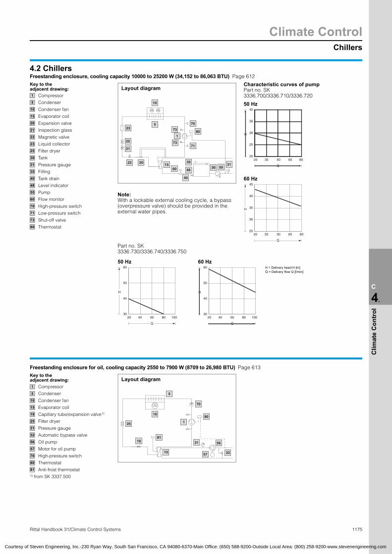
Chillers
Climate Control
1175Rittal Handbook 31/Climate Control Systems
C
4.
Clim
ate
Con
trol
Freestanding enclosure for oil, cooling capacity 2550 to 7900 W (8709 to 26,980 BTU) Page 613Key to the adjacent drawing:
Compressor
Condenser
Condenser fan
Evaporator coil
Capillary tube/expansion valve1)
Filter dryer
Pressure gauge
Automatic bypass valve
Oil pump
Motor for oil pump
High-pressure switch
Thermostat
Anti-frost thermostat1) from SK 3337.500
5
180
31 56
3257
8119
25
15
10
70P
Layout diagram1
5
10
15
19
25
31
32
56
57
70
80
81
Courtesy of Steven Engineering, Inc.-230 Ryan Way, South San Francisco, CA 94080-6370-Main Office: (650) 588-9200-Outside Local Area: (800) 258-9200-www.stevenengineering.com
Characteristic Part no. SK 3336.700/3336.
4.2 ChillersFreestanding enclosure, cooling capacity 10000 to 25200 W (34,152 to 86,063 BTU) Page 612Key to the adjacent drawing:
Compressor
Condenser
Condenser fan
Evaporator coil
Expansion valve
Inspection glass
Magnetic valve
Liquid collector
Filter dryer
Tank
Pressure gauge
Filling
Tank drain
Level indicator
Pump
Flow monitor
High-pressure switch
Low-pressure switch
Shut-off valve
Thermostat
2022
21
25
23
553031
35
48
40
6015
80
71
70573
73
1
10
Layout diagram1
5
10
15
20
21
22
23
25
30
31
35
40
48
55
60
70
71
73
80
60 Hz
3520 50
H
Q
25
30
35
40
45
.
50 Hz
3520 50
H
Q
20
25
30
35
40
.
Part no. SK 3336.730/3336.740/3336.750
Note:With a lockable external cooling cycle, a bypass (overpressure valve) should be provided in the external water pipes.
curves of pump
710/3336.720
65 80
65 80
650 Hz
4020 60 80 100
H
Q
30
40
50
60
.
0 Hz
4020 60 80 100
H
Q
30
40
50
60
.
H = DeliveQ = Delive.
ry head H [m]ry flow Q [l/min]

Climate ControlChillers
1176 e Control Systems
C
4.
Clim
ate
Con
trol
4.2 ChillersFreestanding enclosure for oil, cooling capacity 10600 to 26100 W (36,201 to 89,136 BTU) Page 614Key to the adjacent drawing:
Compressor Pressure gauge
Condenser Automatic bypass valve
Condenser fan Oil pump
Evaporator coil Motor for oil pump
Expansion valve High-pressure switch
Inspection glass Low-pressure switch
Magnetic valve Shut-off valve
Liquid collector Thermostat
Filter dryer Anti-frost thermostat
31
73
152022
21
25
23
81
73
1
70
80
71
56
5732
5
10
M
Layout diagram1 31
5 32
10 56
15 57
20 70
21 71
22 73
23 80
25 81
Courtesy of Steven Engineering, Inc.-230 Ryan Way, South San Francisco, CA 94080-6370-Main Office: (650) 588-9200-Outside Local Area: (800) 258-9200-www.stevenengineering.com
In TS8 modular enclosure system, cooling capacity 6000/7500 W (20,491/25,614 BTU) Page 615Key to the adjacent drawing:
Compressor
Condenser
Condenser fan
Multi-coil vaporizer
Expansion valve
Inspection glass
Liquid collector
Filter dryer
Tank
Pressure gauge
Fixed pump bypass
Filling
Tank drain
Level switch
Pump
High-pressure switch
Thermostat
33
351647
70
201
80
31
5540
30
21
23
25
10
5
Layout diagram1
5
10
16
20
21
23
25
30
31
33
35
40
47
55
70
80
Characteristic curves oPart no. SK 3335.060/3335.075
50 Hz
H = Delivery head H [m]Q = Delivery flow Q [l/min]
3020 40 50
H
Q
12
16
20
24
28
.
.
f pump
60
In TS8 modular enclosure system, cooling capacity 10000 to 25000 W (34,152 to 85,379 BTU) Page 616Key to the adjacent drawing:
Compressor
Condenser
Condenser fan
Multi-coil vaporizer
Expansion valve
Inspection glass
Liquid collector
Filter dryer
Tank
Pressure gauge
Fixed pump bypass
Filling
Tank drain
Level switch
Pump
High-pressure switch
Thermostat
33
351647
70
201
80
31
5540
30
21
23
25
10
5
Layout diagram1
5
10
16
20
21
23
25
30
31
33
35
40
47
55
70
80
Characteristic curves of pPart no. SK
50 Hz 3335.200/3335.250
6030 90 120 150
H
Q
20
26
32
38
44
50
.
50 Hz 3335.100/3335.120/ 3
3020 40 50 60
H
Q
20
26
32
38
44
50
.
H = Delivery head H [m]Q = Delivery flow Q [l/min].
ump
335.150
Rittal Handbook 31/Climat

Chillers/Immersible chillers
Climate Control
1177Rittal Handbook 31/Climate Control Systems
C
4.
Clim
ate
Con
trol
4.2 Immersible chillersUseful cooling capacity 2400 to 77900 W (8196 to 266,042 BTU) Pages 618 – 623Key to the adjacent drawing:
Compressor
Condenser
Condenser fan
Evaporator coil
Expansion valve
Inspection glass
Magnetic valve
Liquid collector
Filter dryer
Tank, to be supplied by the customer
Temperature sensor
High-pressure switch
Low-pressure switch
Thermostat
Stirrer
5
80
70
1
71
30
50822022
23
21
25
10
15
Layout diagram1
5
10
15
20
21
22
23
25
30
50
70
71
80
82
Courtesy of Steven Engineering, Inc.-230 Ryan Way, South San Francisco, CA 94080-6370-Main Office: (650) 588-9200-Outside Local Area: (800) 258-9200-www.stevenengineering.com
4.2 ChillersIn industrial enclosure, cooling capacity 32 kW to 172 kW (109,286 to 587,411 BTU) Page 617
1) Layout diagram SK 3339.300 – .500 available on request.
Key to the adjacent drawing:
Compressor
Condenser
Condenser fan
Evaporator coil
Expansion valve
Inspection glass
Magnetic valve
Liquid collector
Filter dryer
Tank
Pressure gauge
Filling
Tank drain
Level indicator
Pump
Flow monitor
High-pressure switch
Low-pressure switch
Shut-off valve
Thermostat
313060
15
71
80
70
73
10
523
25
21
22 20
73
1
48
35
4055
Layout diagram SK 3339.100/.2001) 1
5
10
15
20
21
22
23
25
30
31
35
40
48
55
60
70
71
73
80
50 Hz 3339.100/3339.200 60 Hz 3339.100/3339.200
907050 110 150130 170
H
Q
35.0
37.5
40.0
42.5
45.0
.8050 110 140 170
H
Q
15
20
25
30
.
Characteristic curves of pumpPart no. SK
50 H
25
30
35
40
H
50 Hz 3339.300/3339.400
1000 200 300 400
H
Q
18
23
28
33
38
.
5
H
0 Hz 3339.500
0 200 400 600 800
Q
20
25
30
35
40
.
H = Delivery head H [m]Q = Delivery flow Q [l/min].z 3339.250, 3339.280
80 120 160 200 250
Q.
50 Hz 3339.450
0 100 200 300 40015
20
25
30H
Q.
35
40
50
45

Climate ControlAir/water heat exchangers
1178 Rittal Handbook 31/Climate Control Systems
C
4.
Clim
ate
Con
trol
85
18
55
1 2
300
150
60
300
276
232
41
150
125
102
Ø 7 (4x)30
0
276
102
150
Ø 7 (4x)
420
200
500
150
Ø 7
80
500
200
420
500
170
503030
133
150
150
160
200
130
145
160
34Ø 74x
18
75
100
12
298
240
475
520
Ø 7
298
520
50
520
298
272
240
475
230
120
127
33
208
Ø 7
135
9321
Courtesy of Steven Engineering, Inc.-230 Ryan Way, South San Francisco, CA 94080-6370-Main Office: (650) 588-9200-Outside Local Area: (800) 258-9200-www.stevenengineering.com
4.3 Air/water heat exchangerMicro, wall-mounted, useful cooling capacity 300 W (1025 BTU) Page 626
Mounting cutout Cooling water connection1Mounting holes
for internal mounting for external mounting Condensate discharge2Wall-mounting, useful cooling capacity 600 W (2049 BTU) Page 627
1
Mounting holes for internal mountingMounting cutoutfor external mounting
Condensate discharge /2″
Cooling water connection 1/2″
1
2
Wall-mounting, useful cooling capacity 1000 W (3415 BTU) Page 627
1
Mounting holes for internal mountingMounting cutoutfor external mounting
Condensate discharge /2″Cooling water connection 1/2″
1
2

Air/water heat exchangers
Climate Control
1179Rittal Handbook 31/Climate Control Systems
C
4.
Clim
ate
Con
trol
Ø 7
(4x)
1192
0
200
140100
18
75
21
80
950
200
175
170 15
475
250
24
126
96
1992
0
950
164
140
Ø 7 (6x)
825
765
350
380
Ø 8
105
45
85
825
380
1
2
30013
3
85
470
200
320
35
75
750
825
25
40
380
Ø 8
400
950
Ø 7
340
340
400
280
112
463
6028
0
904
950
200
21
Courtesy of Steven Engineering, Inc.-230 Ryan Way, South San Francisco, CA 94080-6370-Main Office: (650) 588-9200-Outside Local Area: (800) 258-9200-www.stevenengineering.com
4.3 Air/water heat exchangerWall-mounting, useful cooling capacity 1250 W (4269 BTU) Page 628
Mounting holes Mounting cutout Condensate discharge 1/2″1
for internal mounting for external mounting 2 Cooling water connection 1/2″Wall-mounting, useful cooling capacity 1540 W (5259 BTU) Page 628
Mounting holes for internal mounting
Mounting cutoutfor external mounting
Condensate discharge 1/2″
Cooling water connection 1/2″
1
2
Wall-mounting, useful cooling capacity 2250/3000 W (7684/10,246 BTU) Page 629
Mounting cutoutfor external/internal mounting
Only the 4 mounting holes, 7 mm (0.3″) diameter, are required for internal mounting.
Condensate discharge 1/2″
Cooling water connection 1/2″
1
2
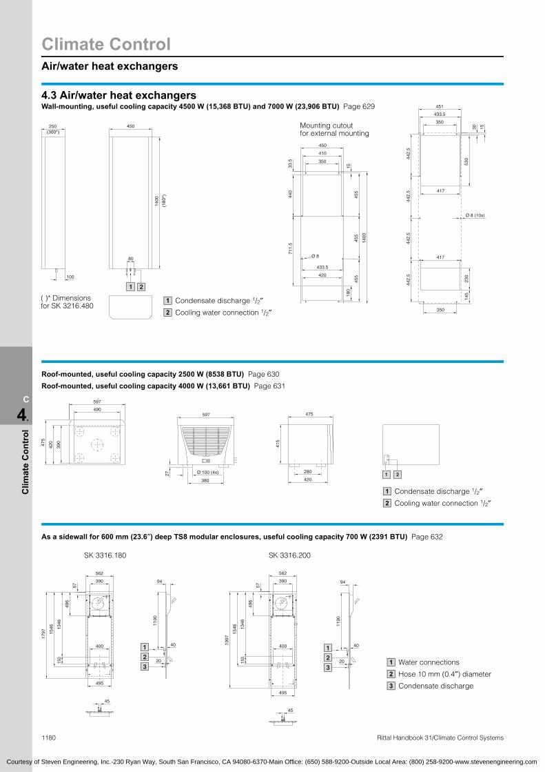
Climate ControlAir/water heat exchangers
1180 Rittal Handbook 31/Climate Control Systems
C
4.
Clim
ate
Con
trol
100
350
410
1533.5
440
711.
5
180
455
455
1400
455
433.5
Ø 8
420
Ø 8 (10x)
350
417
417
442.
5
230
145
442.
544
2.5
442.
5
530
1400
80
21
(300*)
(180
*)
( )* Dimensions for SK 3216.480
490
390
420475
597
380
27 Ø 100 (4x)
475
280
420
415
1 2
1
3
2
1190
40
20
94
1
3
2
1190
40
20
94390
562
57
496
150
1346
1546
1797
495
400
45
390
562
57
496
150
1346
1546
1997
495
400
45
Courtesy of Steven Engineering, Inc.-230 Ryan Way, South San Francisco, CA 94080-6370-Main Office: (650) 588-9200-Outside Local Area: (800) 258-9200-www.stevenengineering.com
250
451
433.5
350
30 15
4.3 Air/water heat exchangersWall-mounting, useful cooling capacity 4500 W (15,368 BTU) and 7000 W (23,906 BTU) Page 629
Mounting cutout450
450
for external mounting
Condensate discharge 1/2″
Cooling water connection 1/2″
1
2
Roof-mounted, useful cooling capacity 2500 W (8538 BTU) Page 630
Roof-mounted, useful cooling capacity 4000 W (13,661 BTU) Page 631
597
Condensate discharge 1/2″
Cooling water connection 1/2″
1
2
As a sidewall for 600 mm (23.6″) deep TS8 modular enclosures, useful cooling capacity 700 W (2391 BTU) Page 632
SK 3316.180 SK 3316.200
Water connections
Hose 10 mm (0.4″) diameter
Condensate discharge
1
2
3

TopTherm air/air heat exchangers
Climate Control
1181Rittal Handbook 31/Climate Control Systems
C
4.
Clim
ate
Con
trol
280
550
501
251
18 x 45°
280
(230)
200
254
524
Ø 8 (4x)
Ø 15 (2x)
266
2549
2
518
550
280
550
150 42
108
4.3 TopTherm air/air heat exchangerWall-mounted, specific thermal capacity 17.5 W/C Page 633
Mounting cutoutfor external mounting
Mounting cutoutfor internal mounting
Internal mounting
External mounting
400
250
345 280
36.5
235
255
950
15
350
25
Ø 9.5 (8x)
385
350
380
Ø 9.5 (4x)
400
370
R6 (4x) 25
920
920
950
2
25 x
45°
950
400 205 (225)
50
155 (175)
Wall-mounting, specific thermal capacity 30 – 60 W/C Page 633
Mounting cutoutfor external mounting
Mounting cutoutfor internal mounting
External mounting
Internalmounting
Dimensions in brackets for 45 W/C and 60 W/C
280
350
Ø 13 (8x)
400
3529
5
380
1580
260
2587
5
320
275
340
400
370
324
324
Ø 13 (4x)
1558
1554
1535
1580
Ø 12 (2x)
25
R6 (2x)
3761580
400 215 50
165
Wall-mounted, specific thermal capacity 90 W/C Page 634
Mounting cutoutfor external mounting
Mounting cutoutfor internal mounting
External mounting
Internal mounting
Courtesy of Steven Engineering, Inc.-230 Ryan Way, South San Francisco, CA 94080-6370-Main Office: (650) 588-9200-Outside Local Area: (800) 258-9200-www.stevenengineering.com

Climate ControlAir/air heat exchangers/rack-mounted climate control
1182 Rittal Handbook 31/Climate Control Systems
C
4.
Clim
ate
Con
trol
200
32.5
130
135.
5
1
147
36
159
400
1 378
1360
3 2
295
380
110
325
275
(655
)
1360
25
30.5
75
350
210
340
280
400
Ø 13
(8x)
Ø 30
Side view
Optional cable pass-through1
542
38
445
3
4.5 Rack-mounted air conditionerFor 482.6 mm (19″), useful cooling capacity 1000 W (3415 BTU) Page 644
482.6 (19″)
190.
5
6 H
E =
265
.9
6.8 x 10.3 220
8032
View of the rear of the unit
Air duct, extendible to any length
Service flap (thermostat)1
1
HE = U
1
2
465.1
482.6 (19″)
76.2
88
380
163
7560
Courtesy of Steven Engineering, Inc.-230 Ryan Way, South San Francisco, CA 94080-6370-Main Office: (650) 588-9200-Outside Local Area: (800) 258-9200-www.stevenengineering.com
400
110
280
5 5
4.5 Air/air heat exchangerWall-mounted Page 633
SK 3129.800 Mounting cutoutfor external mounting
External mounting
Back side
164
Mounting cutoutfor external and internal mounting
4.5 Rack-mounted fanFor 482.6 mm (19″), air displacement 320/480 m3/h (188/283 cfm) Page 645
Rack-mounted fan mounted between Vario rack-mounted fan Vario rack-mounted fan mounted between
a pair of 482.6 mm (19″) rails mounted in subracks 84 HP a pair of 482.6 mm (19″) rails4.5 Centrifugal fanAir displacement 320 m3/h (188 cfm) Page 646
17
Front grille

Climate control tailored to enclosures/heaters
Climate Control
1183Rittal Handbook 31/Climate Control Systems
C
4.
Clim
ate
Con
trol
250
345
265
360
280
Ø 8
With fan
□ 260 x 340
15
50
44420
340
550
500
99
125
20
370
290
475 + 1
260
+ 1
T1
D
36.5
133
223.
5
3
C
B2
110
45 64
185
6445
75
4535
80
125
4535
130
80118
140
25 5.2
8.25
162
100
168
□ 120
Courtesy of Steven Engineering, Inc.-230 Ryan Way, South San Francisco, CA 94080-6370-Main Office: (650) 588-9200-Outside Local Area: (800) 258-9200-www.stevenengineering.com
4.5 Roof-mounted fanAir displacement 360 m3/h (212 cfm) Page 647
Mounting cutout
Without fan
4.5 Roof-mounted fan and vent attachmentAir displacement (unimpeded air flow) 400/800 m3/h (235/471 cfm) Page 647
Mounting cutout
B1
4.5 Fan roof, modular, two-piece for TS/FR(i)Air displacement per fan (unimpeded air flow) 160/180 mm3/h (94/106 cfm) at 50/60 Hz Page 651
For enclosures Cover plate Roof dimensions
C D Part No.TSW (B)mm
(inches)
D (T) mm
(inches)Solid Vented
W(B1)
W(B2)
D(T1)
mm (inches)
600(23.6)
600 (23.6) 2102.180 2102.400
567.5(22.3)
435(17.1)
567.5 (22.3)
400(15.7)
224 (8.8) 7826.366800 (31.5) 2102.190 2102.410 767.5 (30.2)
424 (16.7)
7826.368900 (35.4) 2102.190 2102.410 867.5 (34.2) 7826.3691000 (39.4) 2102.190 2102.410 967.5 (38.1) 7826.360
800(31.5)
600 (23.6) 7885.100 7885.200
767.5(30.2)
635(25.0)
567.5 (22.3)
600(23.2)
224 (8.8) 7826.486800 (31.5) 7886.100 7886.200 767.5 (30.2)
424 (16.7)
7826.488900 (35.4) 7886.100 7886.200 867.5 (34.2) 7826.4891000 (39.4) 7886.100 7886.200 967.5 (38.1) 7826.480
4.6 Enclosure heatersContinuous thermal output 10 – 300 W (40 – 1030 BTU) Page 655
SK 3105.000 SK 3106.000 SK 3107.000 SK 3115.000 SK 3116.000SK 3102.000
including fan
Climate ControlAccessories for climate control
1184 Rittal Handbook 31/Climate Control Systems
C
4.
Clim
ate
Con
trol
79.5
6
71.5
71.5
4.3310
3 3
1
125
132.
5
42
6
280 400
125
42
132.
5
6
Ø 6
258
75
5025
1
32
378
45
6025
Ø 61
3
2
B
A
140
100
160
50 110
90
4.5
10
1.5
8
10
150
210
190
80 40 100
B
A
1.5
8
4.5
10
4.5
270
330
310
50 110
90
B
A
1.5
8
Courtesy of Steven Engineering, Inc.-230 Ryan Way, South San Francisco, CA 94080-6370-Main Office: (650) 588-9200-Outside Local Area: (800) 258-9200-www.stevenengineering.com
79.5 38
4.6 Axial fanFor heater SK 3107.000 Page 655
Grounding lug for M4 or 8 – 32 UNC
1
4.7 Electronic condensate evaporatorPage 665
SK 3301.560/.580 SK 3301.570/.590
258Ø
378ØCondensate hoseSK 3301.608 for SK 3302.XXX SK 3301.610 for SK 3303.XXX
Suggestion for position of cable entry
Hose Length as required
1
2
3
Condensate hose SK 3301.612
Suggestion for position of cable entry
Hose Length as required
1
2
3
4.7 Integrated louversPage 666
SK 2541.235 SK 2542.235 SK 2543.235

Communication Systems
1185
C
6.
Com
mun
icat
ion
Syst
ems
A
1200
800
A
350
1220
1200
800
1200
B B
1200
690
Ø 14
160
B
A
t = 15
10
12.5
90
10
X
A
18
C
12.5
D
B
3
Ø 14
160
1020
.0
.3
.5
.8
.0
.3
.5
.8
.0
.3
.5
.8
.0
.3
.5
1:00
114:00
204:50
219:12
309:36
300:00
414:24
504:48
519:12
609:36
700:00
3
1
4
2
.0
.5
.0
.5
.0
.5
.0
.5
.0
.5
.0
.5
.0
.5
.0
.5
.0
.5
.0
14:00
308:36
503:12
621:48
816:24
1011:00
1205:36
1400:12
1518:48
1713:24
1908:00
2
1
Courtesy of Steven Engineering, Inc.-230 Ryan Way, South San Francisco, CA 94080-6370-Main Office: (650) 588-9200-Outside Local Area: (800) 258-9200-www.stevenengineering.com
6.1 Compact enclosures, outdoorPage 820
1620.000, 1620.100 1621.000, 1621.100 1622.000, 1622.100
820 390
Mounting panelHard masonite
Mounting panelSheet steel
Detail X
Part No. A B C D
1616.200 1133 (44.6)
670 (26.4)
1103 (43.4)
534 (21.0)
1616.210 733 (28.8)
1070 (42.1)
703(27.7)
934(36.8)
1616.220 1133(44.6)
1070 (42.1)
1103 (43.4)
934(36.8)
1616.230 1070 (42.1) ±1
670 (26.4) ±1 – –
1616.240 1070 (42.1) ±1
1070 (42.1) ±1 – –
6.2 Geothermal heat exchangerTerravent Page 831
45
43
41
39
38
36
34
32
31
29
27
25
24
22
20
18Day
Tem
p. °
C
.8
08Time
Internal temperature = Terravent inlet temperature
Terravent outlet temperature
1
2
Night-time operation
Day-time operation
3
4
Rittal Handbook 31/Enclosure Systems
Operating status – cooling: 1300 W (4440 BTU) heat loss from 8 am – 4 pm800 W (2732 BTU) heat loss from 4 pm – 8 amCS Outdoor modular enclosure, thermally insulatedEnclosure size: H x W x D = 1200 x 800 x 500 mm (47.2 x 31.5 x 19.7″)
302725222017151210
7520
– 2– 5– 7
– 10– 12– 15– 17– 20
Day
Tem
p. °
C
.5
.0
1Time
Internal temperature = Enclosure internal temperature
External temperature
1
2
Operating status – heating: No heat loss installed in the enclosureExternal temperature below –10°C (14°F)CS Outdoor modular enclosure, not thermally insulatedEnclosure size:H x W x D = 1200 x 800 x 500 mm (47.2 x 31.5 x 19.7″)

Industrial EnclosuresCommand panels
1186 Rittal Handbook 31/Enclosure Systems
C
1.
Indu
stria
l Enc
losu
res F2F3
F5
F2 F4
F5
F2 F4F3 F2 F4F3
F5
F3 F2 F4 F3 F2 F4
F5
1.5 Command Panel VIP 6000Load specifications for installed equipment Page 160
Permissible installed weightF1 = TotalF2 = Enclosure part
(with support arm connection)F3 = Front partF4 = Rear partF5 = Keyboard housing
Figures in brackets are for hinged version (see 3.1 installation depth, page 161). Enclosures for larger weights available on request.
F2 F2
F5
F2 F4F2F3
F1 = 500 N(112.4 lbf)
F1 = 500 N(112.4 lbf)
F1 = 500/470 N(112.4/105.6 lbf)
F1 = 500/470 N(112.4/105.6 lbf)
F1 = 500/470 N(112.4/105.6 lbf)
F1 = 500/470 N(112.4/105.6 lbf)
F1 = 600/570 N(134.9/128.1 lbf)
F1 = 600/570 N(134.9/128.1 lbf)
F1 = 600/570 N(134.9/128.1 lbf)
F1 = 600 N(570 N)
500 N(112.4 lbf)
450 N(101.1 lbf)
180/150N(40.5/33.7 lbf)
320 N(71.9 lbf)
320 N(71.9 lbf)
130/100 N(29.2/22.5 lbf)
350 N(78.7 lbf)
150/120 N(33.7/
27.0 lbf)
300 N(67.4 lbf)
150/120 N(33.7/
27.0 lbf)
50 N(11.2 lbf)
50 N(11.2 lbf)
50 N(11.2 lbf)
50 N(11.2 lbf)
50 N(11.2 lbf)
180/150 N(40.5/33.7 lbf)
300 N(67.4 lbf)
120 N(27.0 lbf)
130 N(100 N)
300 N(67.4 lbf)
120 N(27.0 lbf)
180 N(150 N)
300 N(67.4 lbf)
120 N(27.0 lbf)
130 N(100 N)
300 N(67.4 lbf)
120 N(27.0 lbf)
Courtesy of Steven Engineering, Inc.-230 Ryan Way, South San Francisco, CA 94080-6370-Main Office: (650) 588-9200-Outside Local Area: (800) 258-9200-www.stevenengineering.com