HERCULES Hercules Incorporated · HERCULES Hercules Incorporated 1010 Marshall Road Jacksonville,...
219
HERCULES Hercules Incorporated 1010 Marshall Road Jacksonville, AR 72076 (501) 982-9481 September 19, 1989 Mr. M. S. Ramesh Project Coordinator Superfund Enforcement Branch (6H-E) United States Environmental Protection Agency - Region VI 1445 Ross Avenue Dallas, Texas 75202-2733 Dear Mr. Ramesh: RE: ADMINISTRATIVE ORDER ON CONSENT DOCKET NO. CERCLA VI-20-89 ^ CO 0 f- Please find enclosed final draft copies of the Quality Assurance ^ Project Plan and the Health and Safety Plan for the Vertac Site RI/FS.O These documents have been revised to be consistent with comments received from the Environmental Protection Agency. Sincerely, HERCULES INCORPORATED Vertac Site Operation Michael J. Faico Project Coordinator MJF: bb cc R. Blanz, w/attachments CHSHill T. Salveter, w/attachments A.D.P.C.E. VT3.4.2 , 03,-OC(,oi 40r7
Transcript of HERCULES Hercules Incorporated · HERCULES Hercules Incorporated 1010 Marshall Road Jacksonville,...

HERCULES Hercules Incorporated1010 Marshall RoadJacksonville, AR 72076(501) 982-9481
September 1 9 , 1989
Mr. M. S. RameshProject CoordinatorSuperfund Enforcement Branch (6H- E )United States EnvironmentalProtection Agency - Region VI1445 Ross AvenueDallas, Texas 75202-2733Dear Mr. Ramesh:RE: ADMINISTRATIVE ORDER ON CONSENT DOCKET NO. CERCLA VI-20-89
^CO0f-
Please find enclosed final draft copies of the Quality Assurance Project Plan and the Health and Safety Plan for the Vertac Site RI/FS.OThese documents have been revised to be consistent with commentsreceived from the Environmental Protection Agency.
Sincerely,HERCULES INCORPORATEDVertac Site Operation
Michael J. FaicoProject Coordinator
MJF: bbcc R. Blanz, w/attachments
CHSHillT. Salveter, w/attachmentsA . D . P . C . E .
VT3.4.2 , 03,-OC(,oi 40r7

QUALITY ASSURANCE PROJECT PLANVERTAC SITE
JACKSONVILLE, ARKANSAS
September 1989
Prepared by:Roy F. Weston, Inc.
West Chester, PennsylvaniaforHercules Incorporated
( W . 0 . # 0267-12-01)
^34,2 ^ 03400001 4018

TABLE OF CONTENTS
SECTION TITLE PAGE1 INTRODUCTION 1-1
1.1 Project Description1.2 Purpose and Scope1.3 Applicability1.4 Data Quality Objectives1.5 Project Schedule
2 ORGANIZATION AND RESPONSIBILITIES2.1 Project Organization2.2 Hercules Responsibilities2. 3 WESTON Responsibilities
2 . 3 . 1 Project Responsibilities2 . 3 . 2 Laboratory Responsibilities
3 SAMPLE COLLECTION
1-11-11-31-41-8
2-1
2-1 vo
2:5-2-5 °2-6 r"~
03-1 0
3 . 1 Operable Unit I 3-23 . 1 . 1 Contents of Process Vessels 3-23 . 1 . 2 Spent Carbon 3-93 . 1 . 3 Containerized Materials 3-113 . 1 . 4 Process Equipment, Building, and 3-15
Structures3 . 1 . 5 Containerized Soils 3-203 . 1 . 6 Trash and Pallets 3-233 . 1 . 7 Electrical Equipment 3-25_
3 . 2 Operable Unit II 3-293 . 2 . 1 Surface Soils 3-293 . 2 . 2 Subsurface Soils 3-343 . 2 . 3 Groundwater , 3-39
3 . 3 Equipment Decontamination 3-473 . 3 . 1 Sampling Equipment 3-473 . 3 . 2 Drilling Equipment 3-49
3 . 4 Sample Containers and Sample Preservation 3-503 . 4 . 1 Sample Containers 3-503 . 4 . 2 Sample Preservation and Holding 3-50
Times3 . 4 . 3 Reagents 3-55
3. 5 Field Quality Control Samples 3-553 . 5 . 1 Field Sample Batches 3-553 . 5 . 2 Duplicate Samples 3-563 . 5 . 3 Field Blanks 3-57
3 . 5 . 3 . 1 Water Field Blank 3-573 . 5 . 3 . 2 Sampling Equipment Field 3-57
Blank
03400001 4C19

TABLE OF CONTENTS (Continued)
SECTION
5
TITLE PAGE3. 5 . 4 Trip Blanks 3-583 . 5 . 5 Matrix Spikes 3-593 . 5 . 6 Split Samples 3-59
3 . 6 Sample Packing and Shipping 3-603 . 6 . 1 Hazardous Material Samples 3-613 . 6 . 2 Environmental Samples 3-63
3.7 Sample Location and Identification 3-64Procedures
3.8 Preventative Maintenance and Calibration 3-65Procedures for Field Equipment
4-1 r-00
4-1 04-3 (4-3 04-64-6 °4-84-84-84-94-94-104-134-13
4-134-15
SAMPLE CUSTODY AND FIELD DOCUMENTATION4.1 Sample Custody Documentation
4. 1 . 1 Responsiblities and Procedures4 . 1 . 2 Sample Custody in the Field4 . 1 . 3 Sample Custody in the Laboratory
4 . 1 . 3 . 1 Sample Receipt4 . 1 . 3 . 2 Sample Storage4 . 1 . 3 . 3 Sample Tracking4 . 1 . 3 . 4 Recordkeeping
4.2 Field Documentation4 . 2 . 1 Field Sample Identification Codes4 . 2 . 2 Field Logbooks4 . 2 . 3 Annotation of Maps4.2 . 4 Chain-of-Custody/Sample Analysis
Request Forms4 . 2 . 5 Sample Labels4 . 2 . 6 Data Collection Forms
LABORATORY CALIBRATION PROCEDURES AND QC 5-1SAMPLES5.1 Glossary 5-25.2 Materials 5-7
5 . 2 . 1 Stock Standard Solutions 5-75 . 2 . 1 . 1 Semi-volatile Analyses 5-75 . 2 . 1 . 2 Volatile Analyses 5-85 . 2 . 1 . 3 Inorganic Analyses 5-85 . 2 . 1 . 4 Secondary Standards 5-8
5.3 Matrix Spike Standards 5-95 . 3 . 1 CLP Organic Analyses 5-95 . 3 . 2 CLP Inorganic Analyses 5-95 . 3 . 3 BTX Analyses 5-95 . 3 . 4 Mon-CLP Semi-volatile Analyses 5-10
5.4 Surrogate Standards 5-105 . 4 . 1 CLP Organic Analyses 5-10
ll
03400001 4020

TABLE OF CONTENTS (Continued)
SECTION TITLE PAGE5 . 4 . 2 CLP Inorganic Analyses 5-105 . 4 . 3 BTX Analyses 5-115 . 4 . 4 Non-CLP Semi-volatile Analyses 5-11
5.5 Internal Standards 5-115 . 5 . 1 CLP Organic Analyses 5-115 . 5 . 2 CLP Inorganic Analyses 5-115 . 5 . 3 Non-CLP Semi-volatile Analyses 5-12
5 . 6 Instrument Calibration 5-125 . 6 . 1 Gas Chromatography/Mass 5-12
Spectroscopy (GC/MS)5 . 6 . 1 . 1 GC/MS Instrument 5-12 r>Calibration -°5 . 6 . 1 . 2 GC/MS Method Performance 5-13°0
Documentation 05 . 6 . 1 . 3 GC/MS Detection and 5-141 .
Quantitation Limits Q5 . 6 . 2 Gas Chromatography (GC) 5-14
5 . 6 . 2 . 1 GC Instrument Calibration 5-14°5 . 6 . 2 . 2 GC Quality Control 5-15
5 . 6 . 3 Atomic Absorption (AA) Spectro- 5-16photometry5 . 6 . 3 . 1 AA Spectrophotometry 5-16
Calibration5 . 6 . 3 . 2 AA Method Performance 5-18
Documentat ion5 . 6 . 3 . 3 AA Detection and Quanti- 5-19
tation Limits5 . 6 . 4 Inductively Coupled Plasma (ICP) 5-19
Spectroscopy5 . 6 . 4 . 1 ICP Calibration 5-195 . 6 . 4 . 2 ICP Quallity Control 5-205 . 6 . 4 . 3 ICP Detection and Quanti- 5-21
tation Limits5 . 6 . 5 Cold Vapor Mercury Analysis: 5-21
Flameless AA (CVAA)5 . 6 . 5 . 1 CVAA Initial Calibration 5-215 . 6 . 5 . 2 CVAA Continuing Cali- 5-22
bration5 . 6 . 5 . 3 CVAA Quality Control 5-225 . 6 . 5 . 4 CVAA Detection and 5-23Quantitation Limits
5 . 6 . 6 Infrared Spectrophotometry (IR) 5-245 . 6 . 6 . 1 IR Calibration 5-245 . 6 . 6 . 2 IR Method Performance 5-25
Documentation5 . 6 . 6 . 3 IR Detection and Quanti- 5-26
tation Limitsill
4C2103400001

TABLE OF CONTENTS (Continued)
SECTION TITLE6 SAMPLE ANALYSIS
6 . 1 Analytical Methods6 . 2 Method Quantification Limits6 . 3 Method Validation
6-16-16-56-5
7 RECORD KEEPING/DOCUMENTATION 7-17.1 Project Documentation 7-1
7 . 1 . 1 Project Document Control 7-17.2 Laboratory Documentation 7-2 0
7.2. 1 Internal Record Keeping 7-3 QQ7 . 2 . 1 . 1 Sample Receipt 7-4 0
tion" "—"—' ———— • - r--7 . 2 . 1 . 2 Sample Tracking Informa- 7-57 . 2 . 1 . 3 Sample Storage Information 7-5 07. 2 . 1 . 4 Sample Extraction Informa- 7-5 0
tion .7 . 2 . 1 . 5 Instrument Calibration 7-57 . 2 . 1 . 6 Analysis Data Sheet 7-67 . 2 . 1 . 7 Copies of Chromatograms 7-67 . 2 . 1 . 8 Data Summary 7-77 . 2 . 1 . 9 Raw QC Data 7-77.2. 1 . 1 0 Laboratory Chronicle 7-7
7 . 2 . 2 Data Reporting 7-77 . 2 . 3 Laboratory Document Control 7-87 . 2 . 4 Field Sampling Document Control 7-9 -
8 DATA MANAGEMENT 8-18.1 Field and Technical Data
. 8 . 1 . 1 Data Reduction8 . 1 . 2 Data Review
8.2 Laboratory Data Internal Procedures8 . 2 . 1 Sample Log-in8 . 2 . 2 Analytical Data8 . 2 . 3 Data Reduction8 . 2 . 4 Data Review8 . 2 . 5 Data Reporting8 . 2 . 6 Data Deliverable Package8 . 2 . 7 Data Archiving
8.3 Data Validation/Usability Review8.4 Data Reporting8.5 Data Archiving
8-18-28-38-48-48-58-68-78-88-98-108-108-128-12
iv
4(2203400001

TABLE OF CONTENTS (Continued)
SECTION TITLE PAGE9 INTERVAL QUALITY CONTROL CHECKS 9-1
9 . 1 Internal Quality Control Samples 9-29 . 1 . 1 Method (Reagent) Blank 9-29 . 1 . 2 Fortified Method (Reagent) Blank 9-29 . 1 . 3 Fortified Sample (Matrix Spike) 9-29 . 1 . 4 Surrogates 9-39 . 1 . 5 Duplicate Field Samples 9-5
9 . 2 Other Internal Quality Control Checks 9-59 . 2 . 1 Laboratory Control Standard 9-59 . 2 . 2 Blind Performance Sample 9-79 . 2 . 3 Known Performance Sample 9-7 °
9 . 3 Field Blanks 9-8 09 . 4 QC Monitoring 9-8 o
10 PERFORMANCE AND SYSTEM AUDITS 10-1r"010.1 General 10-1010.2 Internal System Audits 10-1
10.2.1 Field Audits 10-110.2.2 Laboratory Audits 10-3
10.3 Interval Performance Audits ' 10-410.4 External Systems Audits 10-4
10.4.1 Field Audits 10-410.4.2 Laboratory System Audits 10-5
10.5 External Performance Audits 10-511 PREVENTATIVE MAINTENANCE 11-1
11.1 General Equipment Maintenance and Repair 11-111.2 Field Equipment 11-111.3 Laboratory Equipment 11-2
11.3.1 Introduction 11-211.3.2 Instrument Maintenance Logbooks 11-311.3.3 Instrument Calibration and Main- 11-3
tenance11.3.4 Spare Parts 11-6
12 SPECIFIC ROUTINE PROCEDURES FOR ASSESSING DATA 12-1QUALITY12.1 General Background12.2 Criteria for Acceptance of Data12.2.1 Acceptable Data
12.2 . 2 Unacceptable Data12 . 2 . 3 Historical Data
12-112-212-212-412-4
v
"„ 4C23oa^ooooa?19^

TABLE OF CONTENTS (Continued)
SECTION TITLE PAGE12.3 Procedures for Determining Data Quality 12-5
12.3.1 Statistical Analysis 12-512.3.2 Data Completeness 12-812.3.3 Data Tracking 12-8
13 FEEDBACK AND CORRECTIVE ACTION 13-113.1 Quality Assurance Management 13-113.2 Audits 13-2
13.2.1 Responsibility, Authority, and 13-2Timing
13.2.2 Reports and Distribution 13-3 •'—1 3 . 2 . 3 Forms and Checklists 13-4 u\13.2. 4 System Audits 13-5Q13.2.5 Performance Audits 13-61 3 . 2 . 6 Data Audits 13-7'13.2.7 Feedback Mechanisms 13-80
13.3 Corrective Action 13-9013.3.1 Criteria for Data Acceptability 13-91 3 . 3 . 2 Corrective Action, Responsibility, 13-10
and Authority1 3 . 3 . 2 . 1 Nonlaboratory Activities 13-111 3 . 3 . 2 . 2 Laboratory Activities 13-12
1 3 . 3 . 3 Documentation and Distribution 13-1414 CONTRACTOR QUALITY ASSURANCE REPORTS TO 14-1
MANAGEMENT14.1 Responsbility 14-114.2 Audit Reports 14-214.3 Corrective Action Results 14-2
15 REFERENCES 15-1
VI
"" 402403400001 Q9^

LIST OF FIGURES
NUMBER FIGURE PAGE2-1 Overall Organization Lines of Communication 2-22-2 Laboratory Organization Structure 2-73-1 Process Vessel Inventory Confirmation Checklist 3-33-2 Drum Inventory Confirmation Checklist 3-133-3 Electrical Equipment Inventory Checklist 3-273-4 Monitor Well Constructions 3-42C\J3-5 Typical Groundwater Sampling Form 3-44
04-1 Chain-of-Custody Form 4-2 p-4-2 Sample Flow Chart 4-4 °04-3 Sample Label 4-1413-1 Typical Critical Path for Laboratory Corrective 13-15
Action
vii
:. 40250340C001 ^

LIST OF TABLES
NUMBER TABLES PAGE
1-1 Data Quality Objectives for Each Media and 1-5Material as Outlined in the Work Plan
3-1 Operable Unit I - Analytical Summary 3-53-2 Operable Unit II - Analytical Summary 3-303-3 Sample Containers, Preservation, and Holding 3-51
Time for Operable Unit I3-4 Sample Containers, Preservation, and Holding 3-53
Times for Operable Unit II —6-1 Analytes and Methods for Operable Unit I 6-2 °r-6-2 Analytes and Methods for Operable Unit II 6-3 o6-3 Target Compound List and Quantitation Limits 6-6
for Analyses Performed in Accordance with CLP-SOW6-4 Inorganic Constituents and Quantitation Limits 6-11
for Analyses Performed in Accordance with CLP-SOW6-5 Method Quantitation Limits for 2,3,7,8-TCDD, 6-12
Chlorophenols, Phenoxyherbicides, and Chloro-benzenes
9-1 QA Objectives for Precision of Laboratory 9-4Chemical Analyses
9-2 QA Objectives for Accuracy ( % ) of Laboratory 9-6Chemical Analyses
10-1 Summary of External Performance and System 10-6Audits - WESTON Analytical Laboratories
11-1 Instrument Maintenance Schedule 11-411-2 Calibration Frequency and Mechanism for Major 11-5
Instruments
viii
. 4F2603400001 ^94

Section No. 1Revision No. 0Date: September 14, 1989Page 1 of 8
SECTION 1
INTRODUCTION
1.1 PROJECT DESCRIPTIONf
CTHercules Incorporated (Hercules) and the U. S . Environmental—r-Protection Agency ( U . S . EPA) signed an Administrative Ordeo
0(AO) on 12 July 1989 for conducting a Site investigation at thelocation of the former Vertac Chemical Corporation (Vertac)Facility, Jacksonville, Arkansas (Site). Previous investiga-tions showed that some organic compounds, including toluene,chlorophenols, chlorophenoxyherbicides, and tetrachlorodi-benzo-p-dioxin (TCDD), were found in drums, vessels, processequipment, soils, and groundwater. A detailed description ofthe project and the Site background are contained in Sections1, 2 , and 3 of the AO, Attachment A (Work Plan). Hercules hasretained Roy F. Weston, Inc. (WESTON) to prepare this document.
1.2 PURPOSE AND SCOPE
This document is a quality assurance project plan (QAPP) asrequired by the AO and discussed in Section 3 . 6 . 2 of the WorkPlan. The primary objective of this document is to provide a
4C.2703400001 ^

Section No. 1Revision No. 0Date: September 14, 1989Page 2 of 8
high level of confidence that the environmental data obtainedduring performance of activities described in the Work Plan areof known quality and suitable to address the objective(s) forwhich the data were collected. The sampling rationale,quantity(s), locations, and methodologies are given in the WorkPlan. This QAPP is prepared in compliance with the AO and inaccordance with guidance provided by:
LHON
• U . S . EPA, 1980, U . S . Environmental Protection Agency.r~-Interim Guidelines and Specifications for PreparincQ
0Quality Assurance Proiect Plans. Office ofMonitoring Systems and Quality Assurance,QAMS-005/80.
U . S . EPA, 1985a. Regional Technical Assistance forPreparing Quality Assurance Project and LaboratoryPlans, ROQZ-005/85.
U . S . EPA, September 1987, U . S . EnvironmentalProtection Agency. OTS Guidance Document for thePreparation of Quality Assurance Proiect Plans.Contract No. 68-02-4243.
U . S . EPA, July 1988a with revisions through February1989, Contract Laboratory Program (CLP), Statement ofWork for Organic Analyses. Multimedia. Multiconcen-trations.
4C.2803400001 ^SS£

Section No. 1Revision No. 0Date: September 14, 1989Page 3 of 8
U . S . EPA, February 1988b with revisions through May1989, Contract Laboratory Program (CLP ) , Statement ofWork for Inorganic Analyses. Multimedia. Multiconcen-trations.
• U.S. EPA, 1986, Environmental Protection Agency.Test Methods for Evaluating Solid Waste. SW-846.
00
The scope of this document is to provide for appropriate^r-quality assurance procedures and quality control measures to be^applied throughout the entire program, including:
" • Sample collection, handling, and preservation;• Laboratory analysis of samples;• Data transfer and interpretation; and• Data presentation.
1.3 APPLICABILITY
This QAPP is applicable to activities described in the WorkPlan which is site-specific. It is intended to establishoverall project quality assurance.
This QAPP presents the project organization, objectives,functional activities, and specific quality assurance (QA) andquality control (QC) activities associated with the project.
40290340000i fsw

Section No. 1Revision No. 0Date: September 14, 1989Page 4 of 8
The QAPP is designed to achieve specific data quality objec-tives and to present the general requirements associated withvarious sampling and analysis activities, data generation, datareduction, and reporting. The QAPP is applicable to projectmanagement and field activities performed in accordance withthe Work Plan. The requirements of this QAPP are applicable toaffiliated project personnel, project support groups,r--contractors, and subcontractors. 0
0r-Changes to this QAPP will be submitted to the U . S . EPA by^
0Hercules for review and approval by submitting a marked copy ofthe page(s) indicating the requested changes. U . S . EPA willnotify Hercules within forty-five (45) days of receiptindicating approval or disapproval. Hercules will providecopies of the approved revised pages to the appropriatedocument holders.
1.4 DATA QUALITY OBJECTIVES
Data quality objectives (DQOs) developed for this project attheir broadest level are to assure that the data generated areof a known and suitable level of quality. The DQOs for theRI/FS as outlined in the Work Plan are listed for each mediaand material in Table l-l. The sampling rationale, quan-tity(s), locations, and methodologies are specified in the WorkPlan. These have been based upon historical data which arealso presented in the Work Plan.
03400001', 4030

Section No. 1Revision No. 0Date: September 14, 1989Page 5 of 8
Table 1-1
Data Quality Objectives for Each Media and Materialas Outlined in the Work Plan
MediaOrganic liquids/solids
MixedMan-made Surfaces
Soils
Data QualityObiective(s)1
aMaterial
Contents of Process VesselsPotentially F-listedPotentially non-F-listedand unknown
Spent CarbonFrench drain oily leachateElectrical EquipmentShredded Trash and PalletsProcess EquipmentBuildings and StructuresAsbestosUnderground PipingContainerized SoilsSurface SoilsSubsurface Soils- Source- TCDD Volume- UST
a , b , d , eb , d , eb , d , ec,dcb , d , eb , d , eb , d , e
00CT^0r~-oo
Aqueous Groundwater b, e, fEmpty Process Vessel Rinsate b , d , e
Data Quality Objectives in alphabetical ordera - Characterizing potential organic hazardous constituents
(POHCs) for incinerability and/or assessing materialshandling characteristics.
b - Assessing potential for hazardous chemical constituentsor extent of such constituents, if presence is alreadyindicated.Inventorying and characterizing nature of material.Evaluating potential for onsite landfilling.Supporting Risk Assessment.Monitoring.
^ 403103-iOOOGl81®9

Section No. 1Revision No. 0Date: September 14, 1989Page 6 of 8
To assure that the data generated are of a known and acceptablelevel of quality, the QAPP establishes or makes provisions for:
• Developing standards for performance related tovarious elements of the Work Plan;
Monitoring actual performance in comparison to and in0compliance with the established standards; o\
0r-
Reporting the monitored performance; and 00
• Rectifying performance not conforming to theestablished standards.
Data quality criteria, elements of the DQOs, are described interms of the following:
• Accuracy -'the degree of agreement of a measurement(or an average of measurements), X, with an acceptedreference or true value, T, usually expressed as thedifference between the two values, X-T, or thedifference as a percentage of the reference or truevalue, 100 (X-T/T), and sometimes expressed as aratio, X/T. Accuracy is a measure of the bias in asystem.
403203400001 SS^
Section No. 1Revision No. 0Date: September 14, 1989Page 7 of 8
• Precision - a measure of mutual agreement amongindividual measurements of the same property, usuallyunder prescribed similar conditions. Precision isbest expressed in terms of the relative percentdifference between duplicate measurements or relativestandard deviation between three or more measure-ments. Various measures of precision exist dependingupon the "prescribed similar conditions." 0
0s—
• Representativeness - expresses the degree to which1""'0data accurately and precisely represent aocharacteristic of a population, parameter variationsat a sampling point, a process condition, or anenvironmental condition.
• Comparability - expresses the confidence with whichone data set can be compared to another.
• Completeness - a measure of the amount of valid dataobtained from a measurement system compared to theamount that was expected to be obtained.
Quality assurance measures will be implemented throughout theproject to assure the data have known and suitable qualitycharacteristics such as accuracy, precision, representative-ness, comparability, and completeness. In terms of such
" 4C3303/woooi' ewi

Section No. 1Revision No. 0Date: September 14, 1989Page 8 of 8
characteristics, the quality of data collected must be of asuitable level prior to being reported. Data generated outsidethe constraints of this QAPP, such as split samples andpreviously collected data, must conform to the data qualitycharacteristics listed above to be strictly comparable to datagenerated by activities discussed in this QAPP.
1.5 PROJECT SCHEDULE0
Project activities will be performed according to the scheduleand time requirements as presented in the AO or in Attachment 3'of the AO.
403403400001 0§W-

Section No. 2Revision No. 0Date: September 14, 1989Page 1 of 10
SECTION 2
ORGANIZATION AND RESPONSIBILITIES
2.1 PROJECT ORGANIZATION
C\JThis section describes the organizational structure, lines oOauthority, and responsibilities of key individuals for tha<project. Project activities will be performed within the-0framework of the organization and functions described in thissection. Emphasis is placed on the organization and entitiesresponsible for implementation and administration of this QAPP.The project organization structure showing relationships ofpersons with key responsibilities for this project are shown inFigure 2-1.
The organization for the project is designed to provide clearlines of responsibility and authority, supported-by a managementcontrol structure. This control structure provides for thefollowing:
• Identifying lines of communication and coordination;
• Monitoring project schedules and performance;
'. 4(3503400GC1 08©3

HerculesIncorporated
USEPA Roy F. Weston, Inc.
RegionalAdministrator
Region VI
DirectorEnvironmental
Affairs
ProjectDirector
QualityAssurance
Coordinators
QA Officer CorporateHealth and
Safety
RemedialProject
Manager
Site Manager ProjectManager
Engineeringand Geological
ManagersLaboratory
Engineeringand Geological
Resources
Risk AnalysisManager
Site Contact/Representative
Site OperationsPersonnel
Field TeamLeader
Field Teams
FIGURE 2-1 OVERALL ORGANIZATION LINES OF COMMUNICATION
2-2
4C360340C001 «<?§

Section No. 2Revision No. 0Date: September 14, 1989Page 3 of 10
Managing key technical resources;
Providing periodic progress reports;
Coordinating support functions such as laboratory ordata management; and
• Rectifying deficiencies. r0
In the overall project organization, the management and successof the quality assurance program is attained primarily throughthe responsibilities of the position of the Director ofEnvironmental Affairs. The Director is responsible foractivities performed at the Site in accordance with the AO.
The primary vertical reporting lines within organizations ( U . S .EPA, Hercules, and WESTON) are shown in Figure 2-1 and reflectlevels of authority, responsibility, and communication. Thehorizontal dashed lines connecting organizations reflect theprimary levels and channels of communication. Communicationsat the higher levels will be more issue-related andcommunications at the lower levels will be more activity-specific.
The project organization is supplemented by contractor,administrative, external resource, and support functions.
. 4£303400001 —

Section No. 2Revision No. 0Date: September 14, 1989Page 4 of 10
The administrative structure for each group is the frameworkfor coordinating project activities and manpower, supportfunctions, and other resources including subcontractors andothers, as required. Subcontractor personnel providingservices in support of this project will perform work in strictcompliance with the appropriate contract specifications for theactivity. In addition to project quality assurance, WESTONcorporate-level QA functions (independent of the project) mayinreview, audit, document compliance, identify deficiencies, ancfc)recommend corrective action, if required.
00Quality assurance personnel will have sufficient authority,
organizational freedom, and ability to:
Identify quality assurance problems;
Initiate, recommend, or provide solutions to qualitycontrol problems through designated channels;
Ensure that project activities, including anyprocessing of information, delivery of products, andinstallation or use of equipment is reviewed inaccordance with quality assurance objectives;
Ensure that deficiencies and nonconformances arecorrected; and
^ 403803400003. 6-

Section No. 2Revision No. 0Date: September 14, 1989Page 5 of 10
• Ensure that further processing, delivery, or use ofdata is controlled until the proper disposition of anonconfonnance, deficiency, or unsatisfactoryconduction has occurred.
2 . 2 HERCULES RESPONSIBILITIES
Hercules personnel within the organization structure hold<0overall management responsibility for the project. Herculesopersonnel are the primary contacts with the U . S . EPA. Herculespersonnel are responsible for overall project control ,0
0policies, and strategies.
2 . 3 WESTON RESPONSIBILITIES
2 . 3 . 1 Project Responsibilities
Under direction of Hercules, WESTON is responsible for workassignments encompassing: sample collection; sample analyses;data processing, interpretation, and presentation; and qualityassurance and quality control measures associated with theseactivities. The descriptions of project responsibilities forthe functional roles presented in Section 3.2 of the Work Planrefer to positions contained within WESTON^s organizationstructure.
"_ 4039oa^ooo^L-^<"\sv9V I

Section No. 2Revision No. 0Date: September 14, 1989Page 6 of 10
2 . 3 . 2 Laboratory Responsibilities
The functional roles for some of the key laboratory personnelare described in this section and shown on Figure 2-2. Fromthe project perspective, the structure is designed tofacilitate information exchange between the laboratory and theproject. This exchange includes: planning, technicalrequirements, schedules, and quality assurance and qualityr-control measures. Information exchange with the projectspecifically includes: sample identification, preservation"t -procedures, sample container and glassware requirements, sampIO
0collection procedures, chain-of-custody requirements, cleaningsolvents, sample labeling, packing, holding times, andshipping.
Responsibilities for the key functional titles are described asfollows:
Laboratory Project Director
Earl M. Hansen, Ph.D. will be the Laboratory Project Directorwho will be responsible for ensuring that project needs asreported by the Laboratory Project Manager are identified todivision and laboratory management. The Laboratory ProjectDirector will provide direction/support for administrative andtechnical project staff, interface with laboratory project
. 4(4003/300001^8

WESTON ANALYTICSDIVISION MANAGER
LABORATORYPROJECT DIRECTOR
LABORATORY MANAGER
00
0i—
r-oo
LABORATORYQA COORDINATOR
LABORATORYPROJECT MANAGER
SUBCONTRACTING COORDINATOR LABORATORY REPORT MANAGER SAMPLE CUSTODIAN
FIGURE 2-2 LABORATORY ORGANIZATION STRUCTURE
2-7. 4041
03400001 6BH§Q

Section No. 2Revision No. 0Date: September 14, 1989Page 8 of 10
staff on technical issues, and provide QA oversight foranalytical data.
Laboratory Pro-iect Manager
Ms. Judith L. Stone will be the Laboratory Project Manager whowill be responsible for scheduling project analytical require-ments, monitoring analytical status/deadlines, approving^laboratory reports, and coordinating data revisions/corrections
1—and resubmitting packages to project staff. The Laboratory-Project Manager will prepare/review analytical work and assure.that laboratory personnel understand and conform with elementsof this QAPP related to their activities.
Laboratory QA Coordinator
Ms. Dianne S. Therry is the Laboratory QA Coordinator and willassure conformance with authorized policies, procedures, "soundpractices, and recommend improvements, as necessary. TheLaboratory QA Coordinator will inform the Laboratory ProjectManager of nonconformance to the QA program, introduce controlsamples into the sampling train. In addition, the LaboratoryQA Coordinator will approve laboratory data before reporting ortransmittal to permanent storage and be responsible forretention of supporting information such as control charts and
40420340000:Tx^)

Section No. 2Revision No. 0Date: September 14, 1989Page 9 of 10
other performance indicators to demonstrate that the systemswhich produced the data were in control. The Laboratory QACoordinator will also review results of internal QA audits andrecommend corrective actions and time schedules for theirimplementation.
Laboratory Reports Manager
0The primary responsibility of the Laboratory Reports Manager is—to review analytical reports for format, completeness and typo-"graphical errors. The Laboratory Reports Manager will als<0
0provide technical direction/instruction for the electronictransfer of laboratory data.
Sample Custodian
The on-duty Sample Custodian will be responsible to receivesamples from the field, sign and date shipping .manifests,record date and time of sample receipt, including recordingcondition of both shipping containers and sample containers.
The Sample Custodian will verify and record agreement ornonagreement of information on sample documents such as thesample labels and chain-of-custody forms. If there isnonagreement, the sample custodian will record the
7 4C4303400001-^®^

Section No. 2Revision No. 0Date: September 14, 1989Page 10 of 10
problems/inconsistencies and inform the Laboratory ProjectManager who will resolve the inconsistencies with the ProjectManager or the Field Team Leader.
The Sample Custodian will also label samples with laboratorysample numbers, place samples, and spent samples intoappropriate storage and/or secure areas, and monitor storageconditions. The sample custodian will also release samples toanalysts upon request and replace samples into proper storage"and assure that the chain-of-custody forms have the prope}s-signature and dates.
40440340C001 @@fe

Section No. 3Revision No. 0Date: September 14, 1989Page 1 of 67
SECTION 3
SAMPLE COLLECTION
Samples will be collected and analyzed as specified in the WorkPlan (Sections 4 and 5 ) . Field activities will be performed in jaccordance with the Health and Safety Plan (HASP). Require-^"ments for sampling the following types of materials ara"-
0discussed in this section: Q
• Contents of process vessels• Spent carbon• French drain leachate• Process equipment, buildings, and structures• Containerized soils• Trash and pallets• Electrical equipment• Surface soils• Subsurface soils• Groundwater
This section describes the quality assurance measures necessaryfor the sample collection required by the Work Plan. Protocolsfor collecting samples from most of these materials are
4045034000(4^®

Section No. 3Revision No. 0Date: September 14, 1989Page 2 of 67
specified in Sections 4 or 5 of the Work Plan. Those samplingprotocols are supplemented by some additional aspects ofsampling as described in this section. While the aspects ofsampling presented here are generally focused on qualityassurance, some additional sampling protocols are presentedwhere such protocols are not given in the Work Plan oradditional subsequent clarification may be needed. Qualityassurance measures contained in the Work Plan are incorporated^in this QAPP by reference to the Work Plan.
C-0
3 . 1 OPERABLE UNIT I , Q
3 . 1 . 1 Contents of Process Vessels
Investigation of the contents of process vessels involves thecharacterization of the contents for incineration. Thesampling strategies, as discussed in Section 4.2 of the WorkPlan, are designed to characterize the contents of the vesselsaccording to the process which generated the contents. Thecharacterization of the contents of process vessels willinvolve the confirmation of previous inventory data, assessmentof phases present (liquid or solid), estimation of volume foreach phase, and collection of samples from each such phase. Anexample of an inventory confirmation checklist is shown inFigure 3-1.
4C4603400001^1^

Section No. 3Revision No. 0Date: September 14, 1989Page 3 of 67
Figure 3-1PROCESS VESSEL INVENTORY CONFIRMATION CHECKLIST
I.D. No. ________________ Date Inspected
Size __________________ Inspected By _
Shape __________________ Vessel Grouping
Vessel Contents ________________________
Exterior Conditions _________________________________"^
Previously Sampled (Y/N) _______________________________,—
Insulation Present (Y/N) _____________________________^
Accessibility: 0
Health and Safety __________________________________
Ports ____________________________________________
Pressure __________________________________________
Interior Conditions (Linings) __________________________
Content Volume _______________________________________
Content Phase(s)
Volume of each phase: Liquid ___________ Solid
Type of Entry ______________________________
Potential for Sampling:
Contents _________
Rinsate ________Interior Wipe
Comments:
404703^00003JS»

Section No. 3Revision No. 0Date: September 14, 1989Page 4 of 67
The frequency, protocols, and analytes for the sampling of thecontents of process vessels will be performed as specified inSection 4.2 of the Work Plan and are summarized on Table 3-1 ofthis QAPP. The protocols will be performed in accordance withproper field operations procedures. These procedures willcontain, as a minimum, the following elements to assureappropriate collection, handling, and presentation ofrepresentative samples of the contents of process vessels: ip>
Prior to the commencement of sampling, the vessele-0identified for sampling, as a result of the inven^
tory, will be inspected for accessibility, structuralintegrity, and internal pressure to evaluate whethersampling can be performed safely. Internal pressurewill be checked by reading tank pressure gauges,where present and checking the vessels for anomalousbulges.
Vessels within a common group will be sampledsuccessively.
In addition to the sampling devices identified inSection 4 . 2 . 1 . 1 . 2 of the Work Plan, a peristalticpump using a disposable suction line may be used tosample the liquid contents of process vessels.
4(4803400001 '

Table 3-1
Operable Unit I - Analytical Summary
Analytes
Ultimate Analysis (C,",N,0)Metals (Cf,Pb,Hg,As,Be.Cd,Ba,
Na,K,Mg,Ca)Melting Point (Solids only)Percent ashMoisture content
>5X GS w/thennal conductivityi ) Total chlorine^ Heating value (BTU)
Chlorinated phenolsPhenoxyherbicidesChlorinated benzenes
Priority pollutant metals
AsbestosTCODVolatile OrganicsBase/Neutral/Acid ExtractableOrganochlorine PesticidesToluene
1Analytical Methods
ASTM D3176-D3179EPA 6010 ICAP andSU846 • Method 7471
ASTM D87ASTM D3174<5X Karl Fiseher
ASTM 808 or 2361PASTM D2382-83SU846 • Method 8270SU846 - Method 8150SU846 - Method 8270
SU846 - Series 6000/7000
c Polarized Light MicroscopyCLP SOU • Modified MethodSU846 • Method 8240PSU846 - Method 8270SU846 - Method 8080SU846 - Method 8020
ContentsPotentially
F-Listedf
10-2010-20
0-1010-2010-20
10-2010-20
82o0d
of Process VesPotentiallyNon-F-Listed
9
10-2010-20
0-1010-2010-20
10-2010-20
10-20
10-2010-2010-2010-20
Numfc
sels8
UnknownOrganic
h
7-147-14
0-77-147-14
7-147-14
7-14
7-14®7-147-147-14
er of Fi<
Spent I
Bulki
3
333
33
»ld Samples
:arbon P
Drumi
3
333
33
1^
1^1^\f^
/Material
rocess Equipment,BuiIdings, Cor
and Structuresk
6(R)6(10
6-106(R),46(U),5(D)
6(10
itaSoilslinerize
I
8
88
88888
8
8
Trash Id and
Palletsm
21
2121
2121212121
21
21
French DrainDrummedUastesP
n
11
111
1
1
1111
Notes: a 5 Nurober of samples analyzed will depend on the phases present (liquid solid).b = Number of asbestos sanples collected will be a field determination.c s Analyses for asbestos will be performed in accordance with "Interim Method for the Deterannation of Asbestos in Bulk Samples,'d = 2,3,7,8-TCDD Semi -isomer specific method.e = Analyses may not be performed if EPA sampling data exist.
(Continued on following page.)
0 0 7 1 1 6
EPA-600/M4-92-020.

Table 3-1 (Continued)
f « One composite sample from each phase (liquid/solid) representing about 25X of the nunber of vessels uithin each of the ten groups of conmon processvessels listed in Table 4-2 of the Uork Plan.
g « One composite sample from each phase representing about 2SX of the number of vessels In each group listed in Table 4-4 of the Uork Plan.h » One sample from each vessel identified in Section 4.2.3.i » One composite sample from each of three bulk storage containers.j « Each composite will be formed from samples from ten drums so that about 10X of the approximately 300 drums will be sanpled.k » Rinsate (R): Composite rinse sample from an empty process vessel from each cannon process vessel group Section 4.5.1.1 of the Uork Plan.
Uipe (U): Conposite wipe samples froin process vessels and buildings Section 4.5.1.1 of the Uork Plan.Dust (D): Vacuum samples from five buildings specified in Section 4.5 .1 .1 of the Uork Plan.
I * Each composite formed from sampling about 20 bags. About 10X of the total of 1,600 bags will be sampled as described in Section 4.6 of the Uork Plan.m » Each conposite formed from sanpling about ten bags. About 20X of the total number of bags will be sanpled as described in Section 4.7 of the Uork Plan.n » One composite representing about 25X of the drums.p = Modified frw Table 4-3 of the Uork Plan.
0 0 7 1 1 7

Section No. 3Revision No. 0Date: September 14, 1989Page 7 of 67
• Samples of each vessel will be collected in separatebottles of similar size, labeled, and identified forlater compositing, if appropriate.
• Where appropriate, compositing will be performed bycombining the individual samples of each phase andmixing them. Mixing will be accomplished bystirring. The numbers and services of vessels wherey-composite samples will be collected are specified iri~Section 4.2 of the Work Plan. r—
00
• A representative sample will be collected from themixture, placed into appropriate bottles (Section3 . 4 ) and prepared for shipment to the laboratory.
• The composite sample will be collected for analysesof compounds as listed in Table 4-3 of the Work Plan.
• Preparation for shipment to the laboratory willinclude:
- Sample Identification (Section 4 . 2 . 1 )- Sample Labeling (Section 4 . 2 . 5 )- Sample Preservation (Section 3 . 4 . 2 )- Chain-of-Custody procedures (Section 4 . 1 . 2 and
4 . 2 . 4 )- Packing and Shipping (Section 3 . 6 ) .
03400003

Section No. 3Revision No. 0Date: September 14, 1989Page 8 of 67
• Field QC samples will be collected, including fieldblanks, trip blanks (VOCs only), matrix spikesamples, and duplicates, as specified in Section 3 . 5 .
• Sampling equipment will be discarded or cleaned aftercollecting the sample from each vessel. The cleaningprocedures are described in Section 3 . 3 . CT
• Appropriate information for each sample (individual.and composite) will be recorded in a field logbook.0This will include:
Individual sample identification code
Composite sample identification code
Date, vessel number or composite number, and timeof collection
Physical description ( i . e . , color)
Phase description ( i . e . , liquid or solid)
Preservation and analyses required.
03400001

Section No. 3Revision No. 0Date: September 14, 1989Page 9 of 67
Other field documentation requirements are addressed inSection 4 . 2 . Comments and other relevant observations,such as sampling technique and any modification ofprocedures, will be noted.
3 . 1 . 2 Spent Carbon
Investigation of the stored spent carbon involves the charac-0terization of the carbon for incineration. The frequency <\1protocols, and analytes for the sampling of the carbon are_presented in detail in Section 4.2 of the Work Plan. The
0sampling will be performed in accordance with provisions ofthat section. The protocols will be performed in accordancewith good field operations procedures. These procedures willcontain, as a minimum, the following elements to assureappropriate collection, handling, and preservation ofrepresentative samples of spent carbon:
• Containers of spent carbon to be sampled (both bulkand drummed carbon) will be labeled using indeliblepaint markers.
• Sampling equipment such as a stainless steel scoopsor bucket will be used to collect the carbon samples.
^ 405303^00001^^

Section No. 3Revision No. 0Date: September 14, 1989Page 10 of 67
• A sample from each container which is to be sampled,will be collected in separate bottles of the samesize, labeled, and identified for later compositing.Once samples of each container to be composited arecollected, compositing will be performed by combiningthe individual samples and mixing them. The compo-site sample (s ) to be analyzed will be collected fromthe mixture. —
CM• The composite sample will be collected for analyses
of compounds as listed in Table 4-3 of the Work Plan^0
• Preparation for shipment to the laboratory willinclude:
- Sample Identification (Section 4 . 2 . 1 )- Sample Labeling (Section 4 . 2 . 5 )- Sample Preservation (Section 3 . 4 . 2 )- Chain-of-Custody procedures (Sections 4 . 1 . 2 and
4 . 2 . 4 )- Packing and Shipping (Section 3 . 6 ) . .
• If sampling equipment is not disposable, it will becleaned between samples as described in Section 3 . 3 .
. 4C5403400001 eiss.

Section No. 3Revision No. 0Date: September 14, 1989Page 11 of 67
• Field QC samples will be collected including fieldblanks, trip blanks, and duplicate samples asspecified in Section 3 . 5 .
• Appropriate information for each sample (individualand composite) will be recorded in a field logbook.This will include:
<M- Container I . D . 0- Individual sample identification code s—
r~-- Composite sample identification code 0
0- Date, location, and time of sample collection- Physical description- Preservation and analysis required
Comments and other relevant observations, such assampling technique, will be noted. Field documen-tation requirements are in S-ection 4.
3 . 1 . 3 Containerized Materials (French Drain Oily PhaseMaterial)
The characterization of the containerized materials willinvolve the confirmation of previous inventory data, assessmentof phases present and estimation of volume for each phase.

Section No. 3Revision No. 0Date: September 14, 1989Page 12 of 67
Drums containing oily phase material recovered from the Frenchdrain will be sampled in accordance with Section 4.4 of theWork Plan. An example of a Drum Inventory Confirmationchecklist is shown in Figure 3-2.
The frequency, protocols, and analytes for the sampling of theliquid contents of drums containing oily phase material fromthe French drain are presented in detail in .Section 4.4 of themWork Plan. The sampling will be performed in accordance withc\iprovisions of that section. The protocols will be performed inaccordance with good field operations procedures. The proce-0
0dures will contain, as a minimum, the following elements toassure appropriate collection, handling, and preservation ofrepresentative samples:
• Drums designated to be sampled will be labeled withindelible paint markers. The drums which will besampled will be determined based upon the results ofthe inventory.
• Sampling equipment such as a glass drum thief orstainless steel scoop/bucket will be used to collectsamples.
. 4F>5603^00001 JH |-
Section No. 3Revision No. 0Date: September 14, 1989Page 13 of 67
Figure 3-2DRUM INVENTORY CONFIRMATION CHECKLIST
Label __________________ Date Inspected
Size _________________ Inspected By _
Exterior Condition ______________________
.« -C\jContent Volume
Content Phase ___________;____________________________r^"——————————————————————————————————————————0
Comments: 0
405703400001-8085

Section No. 3Revision No. 0Date: September 14, 1989Page 14 of 67
A sample from the drum which is to be sampled, willbe collected in separate bottles of the same size,labeled, and identified for later compositing. Oncesamples from the designated drums are collected,compositing will be performed by combining theindividual samples from each drum and mixing them.The composite sample(s) to be analyzed will becollected from the mixture. ln
C\lI*--.The composite sample will be collected for analyses
of compounds as listed in Table 4-3 of the Work P.lanQ
Preparation for shipment to the laboratory willinclude:
- Sample Identification (Section 4 . 2 . 1 )- Sample Labeling (Section 4 . 2 . 5 )- Sample Preservation (Section 3 . 4 . 2 )- Chain-of-Custody procedures (Sections 4 . 1 . 2 and
4 . 2 . 4 )- Packing and Shipping (Section 3 . 6 ) .
If sampling equipment is not disposable, it will becleaned between sample locations as described inSection 3 . 3 .
„ 405803400ooi-ea»6

Section No. 3Revision No. 0Date: September 14, 1989Page 15 of 67
• QC samples will be collected including field blanks,trip blanks, and duplicate samples as specified inSection 3 . 5 .
Appropriate information for each sample (individualand composite) will be recorded in a field logbook.
0This will include: (^J—r-
- Drum I.D. 00- Individual sample identification code
- Composite identification code- Date, location, and time of sample collection- Physical description- Preservation and analysis required.
Comments and other relevant observations, such assampling technique, will be noted. Field documen-tation requirements are in Section 4.
3 . 1 . 4 Process Equipment. Buildings, and Structures
Investigation of the process equipment, building, and struc-tures involves the characterization of these materials forremediation. The sampling strategies, as discussed in Section
. 4059O'?/!00r»d ft^a^
Section No. 3Revision No. 0Date: September 14, 1989Page 16 of 67
4.5 of the Work Plan, are designed to determine the extent towhich pieces of equipment and/or buildings:
• Contain residue which may contain contaminantsrelated to past industrial operations.
Contain asbestos. r-(M
The characterization of the process equipment, buildings, and^,structures will involve collecting: ^
0
• Wipe samples from the interior and exterior of selectempty process vessels.
• Rinsate samples from the interior of sample processvessels.
• Wipe samples from buildings.
• Vacuum (dust) samples for TCDD from buildings.
• Samples for asbestos analysis from buildings (andpossibly some process piping).
The rationale, frequency, protocols (with the exception of dustsamples), and analytes for the samples collected from process
0340000103400001

Section No. 3Revision No. 0Date: September 14, 1989Page 17 of 67
equipment, buildings, and structures are presented in detail inSection 4.5 of the Work Plan. The protocols for collectingdust samples are described in this section. The protocols willbe performed in accordance with good field operationsprocedures. These procedures will contain the followingelements to assure appropriate collection, handling, andpreservation of representative samples of the contents of
CDprocess vessels: (\J
r~-• Before any asbestos sampling takes place, ai0
0inventory of buildings and process piping will beperformed to identify potential asbestos contamina-tion. This inventory will identify sample locations,quantity(s), and types. Asbestos samples will beanalyzed in accordance with the method identified inTable 6-1.
Asbestos characterization will be performed byindividuals certified in accordance with the AsbestosHazard Emergency Response Act, 40 CFR 763 (AHERA).
Special handling and shipping requirements forasbestos are provided in Sections 3 . 4 and 3 . 5 .
4(G103^00001 -0^9

Section No. 3Revision No. 0Date: September 14, 1989Page 18 of 67
Wipe samples to be composited will be placed in abottle and labeled after selected areas have beenwiped. The area to be wiped will be determined basedon field conditions and discussions with U . S . EPA.
Three rinsate samples will be collected while drain-ing the water from the third rinse of the selectedoempty process vessels. The individual bottles wilIM
—be labeled and identified for later compositing. ^00
Rinsate samples will be composited by combining theindividual samples and mixing them. The compositesample (s ) to be analyzed will be collected from themixture.
The composite sample will be collected for analysesof compounds as listed in Table 4-3 of the Work Plan.
A vacuum (dust) sample will be collected in a hightraffic area of each of five buildings as describedin Section 4 . 5 . 1 . 1 of the Work Plan. The method usedto collect the dust samples will be consistent withthe following method which was previously used tocollect vacuum samples at office buildings near thesite.
, 4C6203400001 68SQ

Section No. 3Revision No. 0Date: September 14, 1989Page 19 of 67
"Samples were collected with Black and Decker handheld "Dust Busters." Individual "Dust Busters"were used for each office and each vacuum filterconstituted one sample. Dust was collected in hightraffic areas in each office for approximately tenminutes (the duration of the battery life for thevacuums)." (Jacobs, 1 9 8 9 ) .
N t—
Preparation for shipment to the laboratory willyo-include: _0
- Sample Identification (Section 4 . 2 . 1 )- Sample Labeling (Section 4 . 2 . 5 )- Sample Preservation (Section 3 . 4 . 2 )- Chain-of-Custody procedures (Sections 4 . 1 . 2 and
4 . 2 . 4 )- Packing and Shipping (Section 3 . 6 ) .
If sampling equipment is not disposable, it will becleaned between samples as described in Section 3 . 3 .
QC samples will be collected including field blanks,trip blanks, and duplicate samples as specified inSection 3 . 5 .
. 4C6303400001 es l

Section No. 3Revision No. 0Date: September 14, 1989Page 20 of 67
• Appropriate information for each sample (individualand composite) will be recorded in a field logbook.This will include:
- Individual sample identification code- Composite sample identification code- Date, location, and time of sample collection- Physical description _- Preservation and analysis required
r-0Comments and other relevant observations, such as
sampling technique, will be noted. Fielddocumentation requirements are in Section 4.
3 . 1 . 5 Containerized Soils
Investigation of the containerized soils involves the charac-terization of the soils for remediation. The frequency,protocols, and analytes for the sampling of the containerizedsoils are presented in detail in Section 4 . 6 of the Work Plan.The sampling will be performed in accordance with provisions ofthat section. The protocols will be performed in accordancewith good field operations procedures. These procedures willinclude as a minimum, the following elements to assureappropriate collection, handling, and preservation ofrepresentative samples of containerized soil:
4(6403400001@g8

Section No. 3Revision No. 0Date: September 14, 1989Page 21 of 67
Bags of soil which are accessible will be randomlyselected for sampling. Representative samples willbe selected. Bags which are sampled will be labeledwith unique identification codes. The number of bagsto be sampled (160) and the number of composites ( 8 )to be analyzed are specified in Section 4 . 6 . 1 . 1 ofthe Work Plan.
CM^
Sampling equipment (Section 3 . 3 ) such as a stainless""( --steel scoop or bucket will be used to collect theO
0soil samples.
Samples from each bag will be collected in separatebottles of similar size, labeled, and identified forlater compositing. Once samples from each bag to becomposited are collected, compositing will beperformed by combining the individual samples andstirring to mix them. A representative sample(s) tobe analyzed will be collected from the mixture.
The composite sample will be collected for analysesof compounds as listed in Table 4-3 of the Work Plan.
Preparation for shipment to the laboratory willinclude:
. 4(6503/5000010^

Section No. 3Revision No. 0Date: September 14, 1989Page 22 of 67
- Sample Identification (Section 4 . 2 . 1 )- Sample Labeling (Section 4 . 2 . 5 )- Sample Preservation (Section 3 . 4 . 2 )- Chain-of-Custody procedures (Sections 4 . 1 . 2 and
4 . 2 . 4 )- Packing and Shipping (Section 3 . 6 ) .
mIf sampling equipment is not disposable, it will ba<cleaned between samples as described in Section 3 . 3 .
00
QC samples will be collected including field blanks,trip blanks, and duplicate samples as specified inSection 3 . 5 .
Appropriate information for each sample (individualand composite) will be recorded in a field logbook.This will include:
- Bag I . D . number(s)- Composite identification code- Date, location, and time of sample collection- Physical description- Preservation and analysis required
^ 406603400001 w^

Section No. 3Revision No. 0Date: September 14, 1989Page 23 of 67
Comments and other relevant observations, such assampling technique, will be noted. Field docu-mentation requirements are described in Section 4.
3 . 1 . 6 Trash and Pallets
Investigation of the containerized trash and pallets involvestheir characterization for remediation. The frequency,,protocols, and analytes for the sampling of the containerizefOtrash and pallets are presented in detail in Section 4.7 of thp.,Work Plan. The sampling will be performed in accordance witn0provisions of that section. The protocols will be performed inaccordance with good field operations procedures. Theseprocedures will contain as a minimum, the following elements toassure appropriate collection, handling, and preservation ofrepresentative samples of trash and pallets:
Bags of trash and pallets to be sampled will belabeled with unique sample identification codes.
A stainless steel scoop or bucket will be used tocollect the trash and pallet samples.
Samples from each bag will be collected in separatebottles of similar size, labeled, and identified forlater compositing. Once samples from each bag to be
4(6703400001 esss

Section No. 3Revision No. 0Date: September 14, 1989Page 24 of 67
composited are collected, compositing will be per-formed by combining the individual samples and mixingthem. The composite sample(s) to be analyzed will becollected from the mixture.
The composite sample will be collected for analysesof compounds as listed in Table 4-3 of the Work Plan.
inPreparation for shipment to the laboratory will"include: 1 -
00
- Sample Identification (Section 4 . 2 . 1 )- Sampl-e Labeling (Section 4 . 2 . 5 )- Sample Preservation (Section 3 . 4 . 2 )- Chain-of-Custody procedures (Sections 4 . 1 . 2 and
4 . 2 . 4 )- Packing and Shipping (Section 3 . 6 ) .
If sampling equipment is not disposable, it will becleaned between samples as described in Section 3 . 3 .
QC samples will be collected including field blanksand duplicate samples as specified in Section 3 . 5 .
Appropriate information for each sample (individualand composite) will be recorded in a field logbook.This will include:
03400001 tSU8

Section No. 3Revision No. 0Date: September 14, 1989Page 25 of 67
- Bag I . D . number(s)- Individual sample identification code- Composite sample identification code- Date, location, and time of sample collection- Physical description- Preservation and analysis required
v0Comments and other relevant observations, such ast—sampling technique, will be noted. Fiel -
0documentation requirements are in Section 4. —
3 . 1 . 7 Electrical Equipment
The characterization of the electrical equipment onsite willinvolve an inventory of the transformers and capacitors presentat the Site. Before sampling strategies for electrical equip-ment are established, onsite records, utility records andmanufacturers data will be investigated in an attempt todetermine if PCBs were used in the electrical equipment. Anexample of the electrical equipment inventory checklist isshown in Figure 3-3.
If, as a result of the inventory, oil-filled electricalequipment cannot be evaluated as to its PCB content or if thisequipment is identified to contain PCBs, the piece of equipment
03400001 Q^9

Section No. 3Revision No. 0Date: September 14, 1989Page 26 of 67
will be sampled. Electrical equipment will be non-destructive-ly sampled. Sampling will be performed in accordance with goodfield operations procedures. These procedures will contain, asa minimum, the following elements to assure appropriatecollection, handling, and preservation of representativesamples from electrical equipment:
The power source will be cut. >.m—
Plastic sheeting will be used on the ground tct"-0contain spills. Q
A unique indelible code will be assigned toelectrical equipment which is not otherwiseidentified.
The transformer/capacitor will be sampled by removingthe cover of the equipment, if possible, using handtools. The drain plug will not be removed.
^A glass drum thief or vacuum tube will be used tocollect the oil samples.
Samples from each transformer/capacitor will beplaced into bottles and labeled.
\^A[7003400001 - 8-

Section No. 3Revision No. 0Date: September 14, 1989Page 27 of 67
Figure 3-3ELECTRICAL EQUIPMENT INVENTORY CHECKLIST
Date InspectedInspected By _Equipment Type
Serial Number
Site Location
Owner ______
Manufacturer
Date Installed
Oil Present (Y/N)
Records indicated the presence of PCBs (Y/N)
Access for sampling (Y/N) _______________
Comments:
. 4(7103400001 (%^9

Section No. 3Revision No. 0Date: September 14, 1989Page 28 of 67
Preparation for shipment to the laboratory willinclude:
- Sample Identification (Section 4 . 2 . 1 )- Sample Labeling (Section 4 . 2 . 5 )- Sample Preservation (Section 3 . 4 . 2 )- Chain-of-Custody procedures (Sections 4 . 1 . 2 and
4 . 2 . 4 ) 0\m
- Packing and Shipping (Section 3 . 6 ) . .—r-0
If sampling equipment is not disposable, it will b£5
cleaned between samples as described in Section 3 . 3 .
QC samples will be collected including field blanksand duplicate samples as specified in Section 3 . 5 .
Appropriate information for each sample (individualand composite) will be recorded in a field logbook.This will include:
- Sample identification code- Date, location, and time of sample collection- Physical description- Preservation and analysis required
407203400001 0«W

Section No. 3Revision No. 0Date: September 14, 1989Page 29 of 67
Comments and other relevant observations, such assampling technique, will be noted. Fielddocumentation requirements are in Section 4.
3 . 2 OPERABLE UNIT II
3 . 2 . 1 Surface Soils0
Surface soil samples will be collected in accordance withrequirements of Section 5.2 of the Work Plan. The analyticar"-
0methods, analytes, and estimated numbers of samples are showo-on Table 3-2. To characterize the extent of contamination thatmay exist in surface soils at the Site, samples will becollected from points derived from a grid process as describedin Section 5.2 of the Work Plan. The area to be sampled willbe gridded to provide for sample location and identification.Sample collection, compositing and mixing will be performedconsistent with methods described by Jacobs 1989 and other U . S .EPA work on the site. The surface soil sampling procedure willcontain, as a minimum, the following elements to assureappropriate collection of representative samples and tomaintain the integrity of samples that are collected:
Prior to the commencement of surface soil sampling,the corners of the proposed sample grids will beclearly identified on annotated maps and staked so
" 4(7303400001 Wl

U)1
l*>0
Total Petroleum Hydrocarbons SU-9071/E418.1
0U^000-
j.^" /-•».
SM rt^
Analytes
2.3,7,8-TCDO
Chlorophenols
Chlorophenoxyherbicides
Tet rachIorobenzene
Priority Pollutant Metals
Benzene, Toluene, Xylene
Lead
Toluene
Notes:a ' Sampling rationale, frequency, and analytes are db ' Samples from an estimated 120 to 145, 5,000 squar
Three TCDD samples w i l l be collected from each grc « Samples from an estimated 50 to 70, 40,000 squared = Composite samplese = Discrete samples.
Analytical Method(s)
SU-846, Modified Method 8280 360-435
SU-846, Method 8270
SU-8A6, Method 8150
SU-846, Method 8270
SU-846; Series 6000/7000
SU-846. Method 8020
SU-846. SU-6010
SU-846, Method 8020
from soil borings and discrete
Operable uni
SurfaceCentral C
Process Areab
120-145
120-145
escribed in Sece foot, samplinid; one samplefoot, sampling
samples where discoloration
Table :
t I I - Are
Soilslutside CeiProcess Ai
c
50-70
tion 4.2 of the Work Pig grids. Each sample ifor other analytes wi l lgrids. Each sample is
i-2
alyt
itrtrea Process Area Process Area Storage Tank
d d e
:ical Summa
Number o
il Insid
observed.
irya
if Field
Ie Centra
30-75
60-170
60-170
an.s a conp<be eacha compof
1Sanples/
5"b^I Out*
Mite ofgrid.iit< of
Material
irface Soiilde Centr
8-16
8-16
15-20
11 aliquots collected wi th in each grid.
11 aliquots collected within each grid.
I?al Underground
45-60
45-60
45-60
Grounduatere
27-30
27-30
27-30
27-30
0 0 7 1 4 1

Section No. 3Revision No. 0Date: September 14, 1989Page 31 of 67
that individual grid node locations can be accuratelyidentified and marked with pin flags.
• For surface soil samples to be collected in areasinside the central process area (Section 5 . 2 . 2 of theWork Plan), individual soil samples will be collectedat three orthogonal positions located about five feet
(Mfrom each of the eleven nodes in each 5,000 square.foot grid (see Figure 5-2 of the Work Plan)T~rIndividual samples located uniformly at a positio®
0( i . e . , east) will be mixed together and a compositesample for that position will be collected. The sameprocedure will be followed for the other two posi-tions ( i . e . , north and west). Each of the threecomposite samples will be analyzed for 2,3,7,8-TCDDand one of three samples will be analyzed for chloro-phenols and chlorophenoxyherbicides. Analyses willbe .performed using methods described in Section 6 .
• For surface soil samples to be collected in areasoutside the central process area (Section 5 . 2 . 3 ofthe Work Plan) , individual soil samples will becollected from each of the eleven nodes within each40,000 square foot grid. Individual samples will bemixed together and a composite sample will be

Section No. 3Revision No. 0Date: September 14, 1989Page 32 of 67
collected for analysis of 2,3,7,8-TCDD. Sampleanalysis will be performed using methods described inSection 6 .
Surface soils in the area of the tetrachlorobenzenespill will be collected as grab samples to charac-terize the extent of the spill. Samples will bemanalyzed for tetrachlorobenzene using methods^.described in Section 6 . "—
r-00Any sample location that is relocated due to
obstruction will be clearly documented in a fieldlogbook and shown on annotated maps.
Surface soil sample cores will be collected from 0 to6 inches using a cleaned piston corer, King-tubesampler, bucket auger, stainless steel scoop, spoon,or similar device.
The sample will be placed in a clean stainless steel,tempered glass, or aluminum container and will bemixed. Large rock or organic fragments will beremoved from the soil from which the sample will becollected.
407603400001 .e r

Section No. 3Revision No. 0Date: September 14, 1989Page 33 of 67
• Composite samples will be collected for samples to beanalyzed for compounds identified in Section 5 . 2 . 2 or5 . 2 . 3 of the Work Plan, as appropriate. An equalvolume or weight of soil will be collected from eachpoint and the composite will be carefully mixed priorto filling sample bottles.
<• Preparation for shipment will include: •;^-
<;—r-~
- Sample Identification (Section 4 . 2 . 1 ) 0- Sample Labeling (Section 4 . 2 . 5 )- Sample Preservation (Section 3 . 4 . 2 )- Chain-of-Custody procedures (Sections 4 . 1 . 2 and
4 . 2 . 4 )- Packing and Shipping (Section 3 . 6 ) .
• Field QC samples including field blanks and duplicatesamples will be collected as specified in Section3 . 5 .
• Appropriate information for each sample (individualand composite) will be recorded in a field logbook.This information will include:
- Individual sample identification code- Composite sample identification code

Section No. 3Revision No. 0Date: September 14, 1989Page 34 of 67
- Date, location, and time of sample collection- Physical description- Preservation and analysis required.
Conunents and other relevant observations, such assampling technique, will be noted. Fielddocumentation requirements are in Section 4.
in•^
Samples being shipped to the laboratory must follow—r--proper sample custody procedures. These procedures—
are provided in Section 4. ^
3. 2 . 2 Subsurface Soils
Subsurface soil samples will be collected in accordance withSections 5.3 and 5.5 of the Work Plan. The frequency, depth,sample interval(s), analytes and compositing requirements aredescribed in these sections. The subsurface soil samplingprocedure will contain, as a minimum, the following elements toassure appropriate collection of representative samples and tomaintain the integrity of samples that are collected:
• Prior to the commencement of soil boring sampling,the proposed sample locations will be accuratelyidentified and located using annotated maps. Thesample identification system will' be clearly
03400001 4078

Section No. 3Revision No. 0Date: September 14, 1989Page 35 of 67
documented in a manner so that sample locations canbe accurately recalled and surveyed.
Boring locations will be staked at locations mutuallyagreed to by Hercules and the U. S . EPA.
Utility clearance will be obtained by Hercules for a10-foot radius prior to any intrusive activities. \0
t
—Boreholes will be drilled using a hollow-stem auger"0drilling rig. 0
A detailed drilling log and record of samples will bemaintained by the field geologist/soil scientist.
Soil borings will be advanced using an auger with asplit-spoon sampler, split-barrel sampler, or similarsampling device.
Soil samples will be continuously collected from theboreholes that are drilled. These subsurface sampleswill be obtained with a sampling device, driven inadvance of the bottom of the auger hole according tothe ASTM (D-1586) standard penetration test.
03400001 (»^9

Section No. 3Revision No. 0Date: September 14, 1989Page 36 of 67
The sample depth, blow count, and driller's commentswill be recorded in the field log.
Recovered soils will be examined and descriptionswill be recorded in the field log, including samplerecovery, color, grain size distribution, plasticity,and moisture content based on visual observation.Organic vapor detector readings will also ber--
c -recorded. These data will be transferred to a boringlog form. r^"
00
For borings where chlorophenols and chlorophenoxy-herbicides are to be analyzed, a channel samplerepresenting the interval from land surface to split-spoon refusal or groundwater, whichever is shallower,will be collected. A channel sample of soil recover-ed in the sampling device will be removed, placed ina stainless steel, tempered glass, or aluminumcontainer, and mixed. Large fragments and organic•material will be removed prior to mixing. Randomportions of the mixed soil in the container will beplaced in sample bottles for analysis. Duplicate
samples, if required, will be collected from the samemixture.
. 4(8003^0001 98^8

Section No. 3Revision No. 0Date: September 14, 1989Page 37 of 67
If organic staining is observed in subsurface soilsrecovered in these borings, a separate discretesample of the stained soil will be collected andanalyzed. Samples will be analyzed for chlorophenolsand chlorophenoxyherbicides as described inSection 6 .
For borings where 2,3,7,8-TCDD is to be analyzedRO'=1
samples will be collected from soil recovered from-each 12-inch depth interval (12 to 24 inches, 24 to"36 inches, and 36 to 48 inches). Soils recoveredfrom each 12-inch interval will be placed in astainless steel, tempered glass or aluminum containerand mixed. A sample will be collected from themixture for analysis of 2,3,7,8-TCDD using methodsdescribed in Section 6 .
For underground fuel storage tank (UST) borings wherebenzene, toluene, and xylene (BTX) are to beanalyzed, samples will be collected directly from thesampling device and not mixed so that volatilizationis minimized.
The boreholes will be backfilled with cement andbentonite grout and marked with a stake.

Section No. 3Revision No. 0Date: September 14, 1989Page 38 of 67
Preparation for sample shipment will include:
- Sample Identification (Section 4 . 2 . 1 )- Sample Labeling (Section 4 . 2 . 5 )- Sample Preservation (Section 3 . 4 . 2 )- Chain-of-Custody procedures (Sections 4 . 1 . 2 and
4 . 2 . 4 )- Packing and Shipping (Section 3 . 6 ) . 0\
^
Field QC samples will be collected including fieldblanks, trip blanks, and duplicate samples as0specified in the Section 3 . 5 .
Sampling and drilling equipment will be cleaned usingprocedures described in Section 3 . 3 .
Appropriate information for each sample (individualand.composite) will be recorded in a field logbook.This information will include:
- Individual sample identification code- Composite sample identification code- Date, location, and time of sample collection- Physical description- Preservation and analysis required.
4C8?

Section No. 3Revision No. 0Date: September 14, 1989Page 39 of 67
Comments and other relevant observations, such assampling technique, will be noted. Field documen-tation requirements are in Section 4.
3 . 2 . 3 Groundwater
Monitor wells will be installed as described in Section 5.4 ofthe Work Plan. Groundwater samples will be collected in—accordance with Section 5.4 of the Work Plan. The frequence—and analytes of the groundwater samples are described in tha-tf-section also. The groundwater sampling procedure will contain,as a minimum, the following elements to assure appropriatecollection of representative samples and to maintain theintegrity of samples that are collected.
Drilling
• Drilling procedures are discussed in Section 5.4 ofthe Work Plan.
• Drilling equipment will be cleaned prior to use asdescribed in Section 3 . 3 . 2 .
• Drilling locations will be cleared for utilities byHercules for a radius of ten feet around staked welllocations.

Section No. 3Revision No. 0Date: September 14, 1989Page 40 of 67
When coring is necessary, the following protocols will befollowed:
• With the auger flight still in the borehole, abentonite plug will be added to the bottom of theborehole after auger refusal is reached to seal offshallow zones before coring the bedrock. •<—
LH^—
• Drilling rate and water production zones will bodocumented during coring. 0
• As the core is removed from the core barrel, it willbe placed in the core box, beginning at the bottom ofthe core box (this will be the lower right inmulti-sectional core boxes).
• The core will be pieced together so fractures fittogether.
• Core will be washed with water and a brush.
• Core will be allowed to dry.
• Core will be striped with a continuous, vertical red(on right) and black (on left) indelible ink lines.
4081
Section No. 3Revision No. 0Date: September 14, 1989Page 43 of 67
Development will include the removal of three to fivewell volumes, if practical, based on well yields.Development will be completed when pH, temperature,and specific conductance readings have stabilized forthe development water.
Development water will be treated in the onsite wastetreatment plant. c\t
mre-sampling equipment will be cleaned prior to use as-
described in Section 3 . 3 . °
• Wells suspected of having low contaminant concentra-tions will be sampled prior to those suspected ofhaving medium or high contaminant concentrations.
• Record measurements on well sampling forms (Figure3-5..
• Each well will be purged and sampled in accordancewith procedures described in Section 5.4 of the WorkPlan.
• Preparation for shipment to the laboratory willinclude:
Z 408703 00001 WSQ

GENERAL INFORMATIONDate: -_Weather.
Well Number (Purge Well):Reported by: ——————Sampling Team: ————
WELL MEASUREMENTSOther Conunente:
protective Casing: Intact/DamagedLocked: Yea/No Key*.Concrete Base: Intact/DamagedCasing Diameter. ———————Slick-Up Height ———————
HNu/OVA ReadingsInitial:____During Purging; -During Sampling: .
Floating Layer. Yes/NoThickness: ———
Sampled: Yes/No
Depth to Water4
Depth to Wed Bottom4
Column of Standing WaterWefl Volume: ______
(4-A65.6":1.47, S-Aei)Well Evacuation Method: -
(Bailer. Pump, Other)Pump Setting Depth(s)*: ___
Begin Purge Time: -Purging Rate (gpm):
•From Top o< CasingOther Comments: _
FIGURE 3-5 TYPICAL GROUNDWATER SAMPLING FORM
3-44

Observation Well(«)Date: _Weil No..
Purge Well: 1 Well #: 2 Well»-. 3 Well »:Pre-Purge:Depth to Water*/TimeDuring Purging:
Depth to Water'/TimeDepth to Water'/TimeDepth to Waters/Time
End of Purge Time: ————Volume of Water Evacuated:» of Drums Filled: _____
Recovery Rate After Purging: Purge Welb IWefKh 2Wefl«: 3Wefl«:"i "
Depth to Water'/Time —————— —————— —————— —————— L^Depth to Waters/Time —————— —————— —————— —————— ,-Depth to Waters/Time —————— —————— —————— —————— ^Estimated Yield (gpm) —————— —————— —————— —————— '
00
SAMPLE INFORMATION (Pre-Purge) (During Purging) (End Purge)
TimeTemperature °C:pH:Specific ConductOdor Yes/No:Turbid: Yes/No:ColorOther Comments:.
FIGURE 3-5 TYPICAL GROUNDWATER SAMPLING FORM (CONT.)
3-45" 4(>89
03400001W*?

Date: _Well No.Sampling Method:
Bailer (» ) /Pump/Other———————Dedicated to Well: Yes/No
parameters Sampled
PinnrCr Pr—cyth* co^l^Mr ^T SJSSS P"0*^11 Bot Low
__VOA - 0 40 2 Y/N__TOC »fSO^ AQ 00 1 Y/N__ PCa/PMt - AO 1000 1 Y/N__AE/BNA - AG 1000 2 Y/N__ Metal** HN03 P 1000 1 Y/N__CH NtOM P 1000 1 Y/N__Wet Own. - P 1000 1 Y/N__NOj-NOg H2S04 P 250 1 Y/N
•Fittfd: Yn/No
Client Sample »: ——————————————Duplicate: Yes/NoMatrix Spike/Matrix Spike Duplicate: Yes/NoField Blank: Yes/No
Other Comments:
FIGURE 3-5 TYPICAL GROUNDWATER SAMPLING FORM (CONT.)
4090034000016^6
3-46
Section No. 3Revision No. 0Date: September 14, 1989Page 47 of 67
Sample Identification (Section 4 . 2 . 1 )Sample Labeling (Section 4 . 2 . 5 )Sample Preservation (Section 3 . 4 . 2 )Chain-of-Custody procedures (Sections 4 . 1 . 2 and4 . 2 . 4 )Packing and Shipping (Section 3 . 6 ) .
3.3 EQUIPMENT DECONTAMINATION
3 . 3 . 1 Sampling Equipment r -00
After contact with the sample matrix, sampling equipment otherthan disposable sampling equipment, will be cleaned prior tocollecting subsequent samples using the cleaning methodsdescribed in this section. Cleaning will be performed tominimize the potential for cross-contamination of subsequentsamples caused by transfer of contaminants among samples due tosampling equipment. Sampling equipment required to be cleanedis equipment used to collect samples and that came into contactwith the sample matrix.
Disposable sampling equipment will be used to the extentpractical, particularly to collect samples of concentratedliquid materials, such as the contents of process vessels andoily material from the French drain. Contaminant residues fromsuch materials may be difficult to remove.
. 409103400001 SSQ

Section No. 3Revision No. 0Date: September 14, 1989Page 48 of 67
Where cleaning is required for non-disposable samplingequipment (excluding drilling equipment, see Section 3 . 3 . 2 )which has been in direct contact with concentrated liquidmaterials or solids containing visible contaminant staining,the following cleaning method will be used:
Method 1 „
• Rinse in sequence with- 50% methanol/50% water mixture- hexane- methane 1- potable water
• Wash with Alconox solution;• Rinse with DI water; and• Methanol rinse;• Air. dry.
If oily residues are apparent after this cleaning method isperformed, the sequence will be repeated.
Where cleaning is required for non-disposable sample equipmentused to collect samples where no visible organic staining isobserved, the following cleaning method will be used:
. 409203400001 (1SW

Section No. 3Revision No. 0Date: September 14, 1989Page 49 of 67
Method 2
Wash in sequence with- potable water- Alconox solution, scrub with bristle brush, ifnecessary.
Rinse with;- potable water COin- DI water, and _Air dry. r-
00
If a visible oily residue is observed subsequent to performingcleaning using Method 2, then the cleaning process described inMethod 1 will be performed.
3 . 3 . 2 Drilling Equipment
Drilling equipment will arrive onsite in a clean condition.Drilling equipment including the back of the rig, augers, rods,bits, core barrels, and subassemblies will be steam-cleanedusing high pressure hot water upon arrival onsite, betweendrilling each borehole, and before leaving the Site. Split-spoons will be cleaned by scrubbing with a strong Alconoxsolution, and rinsing sequentially with potable water and DIwater. Liquids and solids generated during the steam cleaningwill be collected in a plastic-lined collection area. Liquids
409303400001 9 81

Section No. 3Revision No. 0Date: September 14, 1989Page 50 of 67
will be treated in the waste water treatment plant and solidswill be placed in a drum for subsequent disposal. Theintegrity of the plastic will be maintained where the rig isbacked onto the plastic.
3.4 SAMPLE CONTAINERS AND SAMPLE PRESERVATION
3 . 4 . 1 Sample Containers Cinr--
WESTON's laboratories will provide the sample containers .0I-Chem Level 200 or equivalent bottles will be used as suppliedand will be discarded after use. Sample bottle source andbatch number will be documented.
3 . 4 . 2 Sample Preservation and Holding Times
Samples will be preserved to assure their stability from thetime of collection ' in the field until laboratory analysisbegins.
Tables 3-3 and 3-4 provide a listing of the appropriate samplecontainers, preservation requirements and holding times foreach analyte. Samples will not be held any longer than twodays in the field before shipment to the laboratory. Thelength of time that samples are held in the field prior toshipment will be determined based upon the rate that samples

Table 3-3Sample Containers, Preservation, and Holding Times
for Operable Unit I1
t*»Ln>—
Moisture
Total Chlorine
Heating Value
0&5^00c*s
Jk,
^ 0 0 7 1 6 0
Analyte
Ultimate Analysi(C,H,N,0)
Melting Point(solids)
Percent Ash
(BTU)
Priority Pollutant PMetals
28 days.
Selected MetalsIncinerabilityBa,Be,Ca,Cd,Cr,
'K,Mg,Ng,Pb)
Container
.s G
G
G
G
G
G
except Mercury,
for P(As, except Mercury,Hg, 28 days.
Volume
250 ml
250 ml
250 ml
250 ml
250 ml
250 ml
250 ml
250 ml
rPreservation E>
or
NA
NA
NA
NA
NA
NA
Cool, 40C
Cool, 4°C
laxiaum H<fractionDigestioi
NA
NA
NA
NA
NA
NA
NA
NA
siding Time2
i Analysis
NA
NA
NA
NA
NA
NA
180 days
180 days

Analyte
Chlorophenols
ChlorinatedBenzenes
Chlorophenoxy-herbicides
y 2,3,7,8-TCDDLntsl
VOCssilicone rubber septum
BNAs
OrganochlorinePesticides
0fc? PCBs£-002 Asbestos0U. ,
Container
G
G
G
G
G, with Teflon-lined
G
G
G
P, Air-tight
Table 3-3Containers
Volume ]
250 ml1 Liter3
250 ml1 Liter3
250 ml1 Liter3
250 ml1 Liter3
2 x 40 ml
250 ml
250 ml
250 ml
1 x 125 ml
Preserv
Cool,
Cool,
Cool,
Cool,
Cool,
Cool,
Cool,
Cool,
NA
ation
4°C
4°C
4°C
4°C
4°C
4°C
4°C
40c
Max innExtrad
or Digei
7
7
7
7
7
7
7
im Holdibionstion
days
days
days
days
NA
days
days
days
NA
ng Time2
Analysis
40 days
40 days
40 days
40 days
14 days
40 days
40 days
40 days
NA
G = Glass, Amber wide-mouth with Teflon-lined cap, except as noted for VOCs.| P = Plastic.I-", 1 = For analytes as described in accordance with Section 4 of the Work Plan.»^ 2 = That is the maximum holding time in days from date of collection.
3 = Volume for aqueous samples such as rinsate samples. Q 0 7 1 61NA = Not applicable, v f i u i

Table 3-4
Sample Containers, Preservation, and Holding TimesFor Operable Unit II1
Soil Samples
L»l
»J11 >
Chlorinated
Chloroph«
2,3,7,8-TCDD
Tetrochlorobenzene
8&0000»-»^' 1
3{ ich-n oCO1
Analyte
BenzeneXylene
Phenols
TPH
Lead
0 0 7 1
iSilicone Rubber
Toluene,
anoxyherbic
Container
G.W/TefIon-lined
Septum
G
sides G
G
G
G
G
Volume
2x40 ml
500 ml
500 ml
500 ml
500 ml
500 ml
500 ml
Prese
Cool,
Cool,
Cool,
Cool,
Cool,
Cool,
Cool,
rvation
4°C
40c
4°C
4°C
4°C
4°C
4°C
MaxirnuiExtraction
or Digestior
NA
7 days
7 days
7 days
7 days
7 days
NA
62
i Holding Time2
i Analysis
14 days
40 days
40 days
40 days
40 days
40 days
180 days

L_
Table 3-4 (Continued)Aqueous Samples
Analyte ContainerMaximum Holding Time2
Volume Preservation Extractionor Digestion Analysis
Toluene
Chlorinated
G.W/TefIon-linedSilicone RubberSeptum
G'? Chlorophenoxyherbicides G
2,3,7,8-TCDD G
Priority Pollutant P, with screw capMetals
2x40 ml
1 Liter1 Liter1 Liter1 Liter
Cool, 4°C
Cool, 40CCool, 4°CCool, 4°CCool. 4°CFilterHN03 pH < 2
NA
7 days7 days7 daysNA
7 days
40 days40 days28 days180 days exceptMercury which is28 days.
GP12
NA
Glass, Amber, wide-mouth. Teflon-lined cap, except as noted for BTX and Toluene.Plastic. •-For analytes as described in accordance with Section 5 of the Work Plan.That is the maximum holding time in days from date of collection.Not applicable.
^0W00 0 0 7 1 6 5

Section No. 3Revision No. 0Date: September 14, 1989Page 55 of 67
can be collected so that utilization of QC samples can bemaximized. Field personnel will assure that adequate supplies,such as ice and coolers, are on hand to preserve the samples.The chemical preservatives required will be provided with thesample containers.
3 . 4 . 3 Reagents
Reagents for field decontamination activities will be^.pesticide-grade and supplied by the laboratory. —0
3 . 5 FIELD QUALITY CONTROL SAMPLES
3 . 5 . 1 Field Sample Batches
Field samples will be segregated by matrix. Each field samplewill be part of a field sample batch. Each batch will consistof approximately 20 field samples and will have a sufficientnumber of quality control samples collected to assure that theappropriate quality control measures described in the sectionsthat follow may be attained. Field and laboratory qualitycontrol samples are not included in the 20 field samples in abatch. Quality control samples will be handled and preservedin the same manner as those of the sample batch.
03400001 409903400001 es y

Section No. 3Revision No. 0Date: September 14, 1989Page 56 of 67
A separate chain-of-custody will be completed for each matrix.Samples from different matrices may be shipped to the labora-tory in the same cooler as long as the sample packing andshipping procedures are in accordance with the most restrictiverequirements (Section 3 . 6 ) .
3 . 5 . 2 Duplicate Samples inv0
One duplicate sample will be collected for each batch of 20 oir--0fewer field samples to be analyzed. This frequency i
consistent with the frequency of other quality control samplesrequired by U . S . EPA, SW-846 ( 1 9 8 6 ) .
A duplicate field sample will be collected in the same manneras the field sample. For samples of organic liquids/solids,trash, pallets, leachate, and soils where compositing isrequired, duplicates will be collected directly from thecomposited material, as soon as is practical after collectingthe field sample. For wipe sample and asbestos samples,duplicates will be collected by sampling an area adjacent tothat where the field sample was collected. For aqueoussamples, duplicates will be collected by filling samplecontainers as soon as is practical after collecting the fieldsample.
o::TCtCi .03400001 0880'
-. 4100

Section No. 3Revision No. 0Date: September 14, 1989Page 57 of 67
3 . 5 . 3 Field Blanks
A sufficient volume of field blank material will be collectedin appropriate bottles to provide for the maximum range ofcompounds to be analyzed for the batch. Field blanks will behandled in the same manner as indicated for the field samplesand will be stored and shipped at 4°C.
0v0
3 . 5 . 3 . 1 Water Field Blank ^00A field blank of each source of DI water, distilled water, or
other rinse material used in the final rinse step (Section3 . 3 . 1 ) will be collected. If no sampling equipment is requiredto be cleaned, a water field blank will not be collected. Thefield blank monitors the quality of the final rinse materialused in the cleaning process and will be collected at leastonce, where applicable, per batch of water.
3 . 5 . 3 . 2 Sampling Equipment Field Blank
A sampling equipment field blank will consist of laboratory-grade water poured over or through sampling equipment followingthe cleaning process. This blank provides a check on thecleanliness of sampling equipment. One equipment field blankwill be collected at least once per day during each samplingprogram requiring cleaning of sampling equipment. Where
" 410103400001 oags
Section No. 3Revision No. 0Date: September 14, 1989Page 58 of 67
disposable sampling equipment is used, a field blank from thedisposable equipment will be collected to show the cleanlinessof the equipment. As a target, the overall frequency forcollecting field blanks will be about 1% of the total quantityof disposable sampling equipment used and at least once pertype of disposable sampling equipment.
r--The wipe sample equipment field blanks monitor sample contamOination originating from sample materials and handling at the.Site and will be collected at least once per day during the0wipe sampling program. .
• A wipe sample field equipment blank will be obtainedby donning clean gloves and wiping the cleanedtemplate. The wipe will then be placed in the samplecontainer for analysis.
3 . 5 . 4 Trip Blanks
A trip blank is a sample of laboratory reagent water that isplaced in the appropriate sample bottle and accompanies thesample container (cooler) from the time it is shipped to thefield until it is returned with samples for analysis. Forsamples requiring analysis for volatile organic compounds(VOCs), the trip blank will serve to monitor contaminationduring the course of sample shipment and sample collection, andwill be analyzed for VOCs only. "" 4-1 no
03400001 OS^O
Section No. 3Revision No. 0Date: September 14, 1989Page 59 of 67
Trip blank samples will be supplied by the laboratory and behandled in the same manner as collected field samples. Therewill be at least one trip blank per sampling shipmentcontaining samples for VOC or benzene, toluene, and xylene(BTX) analysis.
003 . 5 . 5 Matrix Spikes v0
(--Sufficient sample volume will be collected so that for eac P
0batch of 20 or fewer field samples for each matrix, thefollowing can be prepared:
• For organic analyses, two fortified (matrix spike)samples to be spiked with appropriate compounds(Section 5 . 3 ) .
• For inorganic analyses, one fortified (matrix spike)sample to be spiked with appropriate compounds(Section 5 . 3 ) .
3 . 5 . 6 Split Samples
Split samples may be collected by U . S . EPA representatives.Representatives will supply the container, container labels,and shipping container (cooler), and they will be present when
410303400001' w^

Section No. 3Revision No. 0Date: September 14, 1989Page 60 of 67
the samples are obtained. Agency codes for these split sampleswill be cross-referenced in the field logbook with the fieldsample identification code described in Section 3 . 7 . Ifavailable, the Agency codes will be recorded in the fieldlogbook when separate samples are collected by Agencyrepresentatives.
CThe split sample for organic liquids, trash, pallets and soil's?T-will be taken from the same mixture as the field sample. Fqt~groundwater samples, the split sample bottle will be filled asnearly coincident as practical with the field sample. The U . S .EPA has represented that 5% will be their overall target forthe number of split samples and that the number of splitsamples would not exceed 10% of the number of field samples.(Personal communications, M . S . Rauesh, August 1 9 8 9 ) .
3 . 6 SAMPLE PACKING AND SHIPPING
The procedures for packaging and transporting samples from ahazardous waste site are dependent upon the degree of hazardassociated with the sample matrix. Environmental samplesobtained from streams, sediments, soils, and groundwater aregenerally considered low hazard. As a general rule, samplesfrom waste sources, drums, tanks, or lagoons are consideredhigh hazard and must be packed, marked, labelled and shipped ashazardous materials according to U . S . DOT regulations. The
r 43,0403400001 0

Section No. 3Revision No. 0Date: September 14, 1989Page 61 of 67
packing and transport of samples obtained during the investiga-tion of the Site will conform to WESTON OP 11-01-008, Shipmentof Hazardous Materials, as outlined below.
3 . 6 . 1 Hazardous Material Samples
Hazardous material samples should be prepared for shipment in0the following manner: ^<;—r-
• Collect sample in specified container and providaocomplete sample identification information requiredon the label. Seal container with custody tape.
• Place labelled sample container in Ziploc bag andseal. Use only one bag per sample container.
• Place sealed Ziploc inside metal paint can andcushion it with vermiculite to prevent breakage andabsorb leakage. Pack one Ziploc per can. Secure lidof can with two strips of tape across the top.
• Place the following labels on each paint can:
- Laboratory address label with sample identificationcode.
430503400001 QSS»
'"" f (J

Section No. 3Revision No. 0Date: September 14, 1989Page 62 of 67
- IATA - Other Regulated Substances UN#8027, Class#9.
- Custody seal on lid.
- "Cargo Aircraft Only" sticker.
Place cans in cooler. Surround cans with vermiculite""for stability during transport. The total sample-volume shall not exceed 40 liters per cooler.
Place sufficient ice in cooler for samplepreservation, if necessary.
• Place completed chain-of-custody form (Section 4)inside plastic bag and attach to the inside coolerlid.
• Secure the cooler lid with packing tape.
• Place completed custody seal on two opposite sidesof the lid.
• Place upward pointing arrow label on the fourvertical sides of the cooler.
03400001 Q8^°6

Section No. 3Revision No. 0Date: September 14, 1989Page 63 of 67
Place the following labels on the top of the cooler:
"Other Regulated Substance, UN#8027, Class # 9 . "
"Cargo Aircraft Only."
- "Inside Packages Comply with PrescribedSpecifications." f"
r -00- "This End U p . "
3 . 6 . 2 Environmental Samples
Samples, which in the field are not considered to be highhazard, may be shipped as environmental samples and handled as *follows:
Collect sample in specified container and providecomplete sample identification information requiredon the label. Seal container with custody tape.
Place labelled sample container in Ziploc bag andseal. Use one bag per sample container.
Place samples in a cooler. Surround samples withvermiculite for stability during transport.
430703400001 eess

Section No. 3Revision No. 0Date: September 14, 1989Page 64 of 67
• Place sufficient ice (approximately 10 pounds) in thecooler for sample preservation.
• Place completed chain-of-custody form (Section 4)inside plastic bag and attach bag to the insidecooler lid. ,_r<i
r-s—
• Secure the cooler lid with packing tape. y-_00
• Place completed custody seal on two opposite sides ofthe lid.
• Place upward pointing arrow label on the fourvertical sides of the cooler.
3 . 7 SAMPLE LOCATION AND IDENTIFICATION PROCEDURES
To define where each sample was collected and to providecontrol and tracking of sample results, sample location andfield identification procedures will be carefully followed.The field sample identification will include:
• Site;
Sample type/matrix;_ 4108
03400001 e®W
Section No. 3Revision No. 0Date: September 14, 1989Page 65 of 67
Sample location; and
Distinction of sample type, such as duplicate, spike,or blank.
In order to relocate a sample location at a future time, key,^.grid points will be staked and surveyed. If locations are•t—changed because of field conditions, the new sample location"-
0will be noted on the map and this will be described in the-field logbook.
3 . 8 PREVENTATIVE MAINTENANCE AND CALIBRATION PROCEDURES FOR
FIELD EQUIPMENT
Proper field equipment and instrument performance is essentialto obtaining reliable data. An inventory control systemgoverning equipment maintenance and instrumentation calibrationwill be maintained. The inventory control documentationincludes, but is not limited to the following:
Description of instrument;
Manufacturer, model number, and serial number;
• Identification number (if different from the above) ;
410903400001 wSy

Section No. 3Revision No. 0Date: September 14, 1989Page 66 of 67
Name, address, and telephone number of company thatservices the instrument or equipment;
Type of service policy; and
• Timing and frequency of routine maintenance,inservicing, and calibration, r--
\—r-
Procedures for field instrumentation and equipment maintenance ,00repair, and calibration are in accordance with the manufac-
turer's specifications. Preventive maintenance will also beaddressed by daily checks of equipment prior to initiation offield operations to allow time for replacement of malfunction-ing meters or other parts. The Field Team Leader will beresponsible for implementing and documenting the calibrationprocedures used while conducting field operations.
Field equipment requiring preventive maintenance andcalibration may include, but is not limited to, the following:
• Field pH meter;• Specific conductance meter;• Water level probe.
. 411003400001 (W8-

Section No. 3Revision No. 0Date: September 14, 1989Page 67 of 67
It is anticipated that some or all of these types of equipmentmay be utilized for the field operations. Maintenance of suchequipment, where required, will be in accordance withmanufacturers specifications.
Calibration of the pH meter will utilize a pH 4 and pH 7 buffersolution each time the instrument is turned on. The use ofO
f-these buffers is based upon a review of groundwater data_presented in Appendix E of the Work Plan which indicates thatthe groundwater pH ranges from approximately 4 to 7. 0
Calibration of the specific conductance meter will be checkedeach time the instrument is turned on by performing a standardred line calibration check which utilizes an internalcalibration standard.
. 411103400001 WS9

Draft - Do Not Cite or Quote Section No. 4Revision No. 0Date: September 12, 1989Page 1 of 16
SECTION 4
SAMPLE CUSTODY AND FIELD DOCUMENTATION
4.1 SAMPLE CUSTODY DOCUMENTATION r"~r~-
Chain-of-custody is a term that identifies the sequential1*""0
history of individuals who were in control or possession of asample or group of samples. The chain-of-custody record is awritten record that is used to identify and track the samplefrom the time it is collected. It includes such information asthe date, time, and location of sample collection, name(s) ofsampler, and any transfer of custody.
WESTON personnel will follow the chain-of-custody procedures toassure preservation of the integrity of each sample. Chain-of-custody records will be used for sample manifesting on theproject. The chain-of-custody records will be initiated in thefield at the time of sample collection and will follow eachbottle through completion of chemical analysis. A copy of thisform is included as Figure 4-1.

WESTON Analytic* Us* Only Custody Transfer Record/Lab Work RequestWESTON Analytic* Use Only
Client ——Work OrderOaf Rec'd..RFW ContactClient Contx
MA use OnlyLab ID
Matrix: W • Water OS • Orum Solid*S-Soll 0-011 DL • Drum LiquidsSE-Sedlment A-AIr F-FlahSO-Solld X-Othf
Item/Reason
•rt/Dhftn»
Client ID/0—criptlon
Rifnwl^ by Received bv
Custod
Special Inatmctlona:
Date Tim*
y Transfer Record/Lab Work Request NJC^TOKJRefrigerator*•TTyp* ContainerContalnw/Volum*Pra—rvatlva
ANALYSES ^.REQUESTED '
Matrix DataCollected
Item/Reason Rdinouished bv
— 0 0 7 1 3 - 0 — — — — —
Received bv Date
•
Tim*
WESTON AnalyticsUse OnlySamples Were:
1 Shipped or Hand-OeXvered
NOTES:
2 Ambient or ChilledNOTES:
3 Received Broken/Leaking (ImproperlySealed)Y N
NOTES:
4 Properly PreservedY N
NOTES:
5 Received WithinHolding TimesY N
NOTES:
COC Tape Was:1 Present on Outer
Package Y N2 Unbroken on Outer
Package Y N3 Present on Sample
Y N4 Unbroken on SampleNOTES: Y N
COC Record Was:1 Present Upon Receipt
o( Samples Y NDiscrepancies BetweenSample Labels and COCRecord? Y NNOTES:
RFW21-21-001/A-5/88
FIGURE 4-1 CHAIN-OF-CUSTODY FORM

Draft - Do Not Cite or Quote Section No. 4Revision No. 0Date: September 12, 1989Page 3 of 16
4 . 1 . 1 Responsibilities and Procedures
The Field Team Leader is responsible for the samples from thetime they are collected until they are shipped to the labora-tory. A copy of the shipping invoice will be attached to thechain-of-custody. The Sample Custodian receives the samples atthe laboratory and initiates the laboratory custody protocol.0The Laboratory Project Manager has ultimate responsibility for~-the samples once they are received in the laboratory. A^typical sample flow chart (Figure 4-2) outlines the responsi0bilities pertaining to field and laboratory custody proceduresbased upon the specific related activities.
4 . 1 . 2 Sample Custody in the Field
A written record of the chain-of-custody facilitates theidentification and tracking of a sample throughout thecollection/analysis process.
The chain-of-custody protocol will follow U . S . EPA NationalEnforcement Investigation Center (NEIC) procedures described inthe document NEIC Policies and Procedures. Revised June 1985b,EPA-330/9-78-110-R. A single form is permissible for bothchain-of-custody and sample analysis request purposes.Individual samples will be entered on the form followingcollection. The following information will be included on thechain-of-custody form(s): " " AIIA
03400001 o®^.
Sampling •nd Analysis Plan Lab Director and Supervisors: Projaci Manag«r and Field Team Supervisors(co Oar Managament Coordinator and QA/QC Coordinator)
Chain of Custody'Sampling •nd Transportation
Sample Racalpt
tLOQ In
Flald Team
Oala Managamant Coordlnalor and QA/QG Coodlnalor
(Holding llm*: QA; Promlfd complaUon date) Oala ManaganrniCoordination •nd QA/QC Coordinator
- •Priorlly A Paraonnal Scheduling Lab Director •nd Suparvliora11 riacarary
ConacllvAcllon
(Lab DIraclor •ndSupafvJiora)
QA/QC Report(QA/QC Coordlnalor)
Ana yala and QC (QA •piking) Lab paraonnal (QG control chart*)
Data ManagamenI Coordinator(•IgnlllcMil llguraa •nd cornpleteneia)
Raiulla
QA/QG Check QA/QO CoordinatorI Paw
Invoice Oala ManagamenI Coordinator
Supervlaor Check L«b Director •nd 8up«ntoor«
tRaaulf Releaaad
Sample Olipoaal
Data ManagamenI Coordinator
Data Management Coordinator; Lab Director and Supervisors
0 0 7 1 8 0
FIGURE 4-2 LABORATORY SAMPLE FLOW CHART

Draft - Do Not Cite or Quote Section No. 4Revision No. 0Date: September 12, 1989Page 5 of 16
• Project site;
• Date of collection;
• Field sample identification codes;
• Sample type and description (organic liquid or sol id^wipe, dust, soil, water, or other) ; "r-
Is-0
• Analyses requested; and
• Special handling and storage requirements.
This information will also be reflected on the individualsample labels as specified in Section 4 . 2 . 5 . Furthermore,appropriate sample information will be recorded in the fieldlogbooks as described in Section 4 . 2 . 2 . Each shipment ofsamples will be accompanied by the completed, signed and datedchain-of-custody/sample analysis request form(s).
Custody seals will be placed on each sample at the time ofcollection and on each shipping container prior to shipment.Collected samples will be under lock and key or under visualcontrol until their shipment to the laboratory. The Field Team
; 411603400001 9 4

Draft — Do Not Cite or Quote Section No. 4Revision No. 0Date: September 12, 1989Page 6 of 16
Leader will act as sample custodian and document controlofficer to monitor the location of collected samples and toassure that appropriate sample information is recorded in fieldlogbooks•
After sample collection and prior to shipment, samples will bepackaged and labeled (Section 3 . 6 ) according to DOT shipping
CMregulations and preserved (Section 3 . 4 ) in such a manner tgassure sample integrity during shipment. The chain-of-custodyT"n-sample analysis request form(s) will be securely attached t®
0the shipping container. The lids of the shipping containerwill be secured with strapping tape and sealed with custodytape. Shipments will be delivered to the laboratory bydedicated vehicle or common carrier in accordance with theappropriate Federal DOT shipping regulations.
4 . 1 . 3 Sample Custody in the Laboratory
The following sections describe chain-of-custody proceduresassociated with sample receipt, storage, preparation, andanalysis and general laboratory security procedures.
4 . 1 . 3 . 1 Sample Receipt
A designated sample custodian is responsible for samplesreceived at the laboratory. This individual is aware of
" 4117034000010»

Draft - Do Not Cite or Quote Section No. 4Revision No. 0Date: September 12, 1989Page 7 of 16
custody requirements and the potential hazards of dealing withenvironmental samples. In addition to receiving samples, thesample custodian will also be responsible for documentingsample receipt, storage before and after sample analysis, andthe proper disposal of samples. Upon sample receipt, theSample Custodian will:
m• Inspect the sample container for integrity. Th®opresence of leaking or broken containers will be~noted on the chain-of-custody/sample analysis requesO
0form(s). The Sample Custodian will sign (with dateand time of receipt) the chain-of-custody/sampleanalysis request form(s), thus assuming custody ofthe samples, and will assign the laboratory sampleidentification numbers;
• Compare the information of the chain-of-custody/sample analysis request form(s) with the sample tagsand labels to verify sample identity. Any inconsis-tencies will be resolved with a field samplingrepresentative before sample analysis proceeds;
• ' Store samples in accordance with Section 4 . 1 . 3 . 2 ; and
• Alert the project manager, laboratory managers, andsection managers of analyses requiring immediateattention because of short holding times. - ..no•'•J-JLo
03400001 08SB

Draft - Do Not Cite or Quote Section No. 4Revision No. 0Date: September 12, 1989Page 8 of 16
4 . 1 . 3 . 2 Sample Storage
Samples will be maintained in a locked storage refrigerator at4°C ± 2°C. Provisions will be in place to handle emergencyconditions, such as power outages. The laboratory willmaintain controlled building access. •^
004 . 1 . 3 . 3 Sample Tracking ^
00
Each sample will receive a unique WESTON sample number at thelaboratory when it is logged into the laboratory computer.Each person handling a sample batch will note the locationchange, time, date, and reason for movement.
For samples that require extraction or digestion prior toanalysis, a sample extraction or digestion record will beprepared at the time of extraction or digestion. Laboratorydata will be entered on the sample extraction form via computerand permanently recorded in a bound laboratory logbook.
4 . 1 . 3 . 4 Rccordkeeping
Data related to sample preparation and analysis, as well asobservations by laboratory analysts will be permanentlyrecorded in bound laboratory logbooks. Laboratory logbook
411903400001 OW7

Draft - Do Not Cite or Quote Section No. 4Revision No. 0Date: September 12, 1989Page 9 of 16
pages will be signed and dated daily by laboratory analysts.Corrections to logbook entries will be made by drawing asingle line through the erroneous entry and writing the correctentry next to the one crossed out. Corrections will beinitialed and dated by the analyst.
4.2 FIELD DOCUMENTATIONinCO
Documentation of field sampling will be performed to assure"^r"~data validity and facilitate analysis and evaluation. Thaspecific documentation .requirements are identified in thefollowing sections.
4 . 2 . 1 Field Sample Identification Codes
The field sample identification code provides the tracing ofthe sample from the location in the field, through laboratoryanalysis, and finally to data evaluation and presentation. Itis essential that the integrity of the field sample identifica-tion code not be compromised.
Each sample will be assigned a unique field sample identifica-tion code and labeled accordingly. This field sample identi-fication code will contain information traceable to the type,location where the sample was collected, and other informationappropriate to that sample. This code will be used for
" 41 003400001tg®

Draft - Do Not Cite or Quote Section No. 4Revision No. 0Date: September 12, 1989Page 10 of 16
references to this particular sample in field and projectdocumentation and reports.
4 . 2 . 2 Field Logbooks
Field logbooks will be maintained containing informationpertinent to the field sampling program and the equipment
\0preparation efforts. Field logbooks will be bound and entrieswill be made in ink. Correction will be made by drawing a line"^"r-through the incorrect entry and writing in the correct entry .QThe person making the correction will date and initial thecorrection. The Field Team Leader will review field logentries daily and initial each page of entries. Field logbookswill be maintained by the Field Team Leader or anotherdesignated field team member during field activities andtransferred to the project files to provide a record ofsampling. Field logbooks will contain the following:
Name and location of site;
Date(s) and time(s) of sample collection;
Name of Field Team Leader and other field teammembers ;
Field observations;
' 412103400001 (% 9

Draft - Do Not Cite or Quote Section No. 4Revision No. 0Date: September 12, 1989Page 11 of 16
• Summary of equipment preparation procedures;
• Number and type of samples taken and sampleidentification codes;
• A cross-reference of sample identification codes tosampling points composites or grids that may ber~-indicated on annotated maps or sketches; 00
—r-
• A description of sampling methodology, or reference0to the QAPP and/or Work Plan;
• A description of the method used for mixing orcompositing; and
• A cross-reference to photographs, if photographs aretaken.
In addition, the following observations about each samplecollected for analysis will be recorded in the logbooks, asappropriate:
• Sample depth;
• Color and texture;
"- "" 45,2203400001 ffi»a

Draft - Do Not Cite or Quote Section No. 4Revision No. 0Date: September 12, 1989Page 12 of 16
• Physical description;
• Type(s) of laboratory analyses requested; and
• Any changes in sampling locations (these changes arealso to be indicated on annotated maps, if
00appropriate). OQ
r--A separate logbook of information pertinent to health and?
0safety may be maintained. Examples of this informationinclude:
• Real-time personnel air monitoring results, whenapplicable;
• Heat/cold stress monitoring data, if applicable;
• Upgrades or downgrades of personnel protectiveequipment; and
• Reason(s) for upgrades or downgrades (documentingappropriate approvc.ls) .
412303400001 0 @a

Draft - Do Not Cite or Quote Section No. 4Revision No. 0Date: September 12, 1989Page 13 of 16
4 . 2 . 3 Annotation of Maps
Copies of the base maps or sketches will be used by the fieldteams to record key site conditions and to show approximatelocation of: vessels; drums; buildings, and structures; bagsof trash, pallets, and soils; surface soil grids; monitoringwells; and other appropriate sampling sites. The maps or.-^sketches will be maintained by the Field Team Leader during30
field activities and transferred to the project files for af -0record of sampling locations. —
4 . 2 . 4 Chain-of-Custody/Sample Analysis Request Forms
Chain-of-custody/sample analysis request form(s) become anessential part of the field documentation. A description ofthe forms and procedures for their use is presented in Section4 . 1 .
4 . 2 . 5 Sample Labels
Samples will be labeled appropriately. Figure 4-3 illustratestypical sample labels to be used during sampling activities.Sample labels will provide the project site, time, and date ofcollection, analysis requested, preservation method, and thesample code unique to the sample.
412403400001 0§^

^Vl^h^^ as< WELSH POOIROAO\JL4AUFl*JsJ UONV1UA PA 1B3S3
-.SBV /W.SSS..-? (21 S) 524.01 M
PROJECT:Sample 10
RFW»
Comments:
Date Time Sampler
FIGURE 4-3 SAMPLE LABEL
4-14 ' 412503400001 0888

Draft - Do Not Cite or Quote Section No. 4Revision No. 0Date: September 12, 1989Page 15 of 16
4 . 2 . 6 Data Collection Forms
In addition to the documentation required in previous sections,some field activities will be documented on data collectionforms. Examples of some of these forms are included in samplecollection discussions in Sections 3 . 1 and 3 . 2 . The datacollection forms used depend on the type of activity or
—sampling such as monitoring well installation, surface soilo\sampling, or subsurface soil samples. The sampleidentification used on the data collection form will be^
0consistent with Section 4 . 2 . 1 guidelines for field sampleidentification codes.
Data collection forms provide the means to record data thatwill be used to assess sampling conditions, material proper-ties, and/or the composition of environmental samples. Byillustrating the methods to be adhered to in the reporting ofdata, as well as identifying appropriate units of measure oroptional test procedures, the data collection forms willprovide a measure of quality control in the sample collectioneffort.
The detailed and explicit nature of the forms will serve toassure that data are measured in a consistent format, therebyreducing individual interpretations or preferences. Thisapproach overcomes many difficulties that may be anticipated innotetaking among field personnel. " 41,26
03 00001 068.1
Draft - Do Not Cite or Quote Section No. 4Revision No. 0Date: September 12, 1989Page 16 of 16
Data collection efforts are also guided toward completeness bythe nature of the information required to adequately representan observation. From the organization and layout of each datacollection form, the data necessary to accurately characterizea particular property or relationship are apparent. Thisreduces the likelihood of initiating field sampling or o.laboratory analyses, only to discover that key pieces of 0\
information have not been collected and further sampling is r-~-0required. Q
03400001 W&5

Section No. 5Revision No. 0Date: September 14, 1989Page 1 of 26
SECTION 5
LABORATORY CALIBRATION PROCEDURES AND QC SAMPLES
Analytical procedures cited in this QAPP reference themfollowing: ON
r-• U . S . EPA, July 1988a with revisions through FebruaryO
01989, Contract Laboratory Program (CLP), Statement ofWork for Organic Analyses. Multimedia. Multiconcen-trations. ( U . S . EPA CLP-SOW, Organic Analyses).
U . S . EPA, February 1988b with revisions through May1989, Contract Laboratory Program (CLP), Statement ofWork for Inorganic Analyses. Multimedia. Multiconcen-trations. ( U . S . EPA CLP-SOW, Inorganic Analyses) .
U . S . EPA, November 1986, Environmental ProtectionAgency, Test Methods for Evaluation Solid Waste.Physical/Chemical Methods. Third Edition, Revision 0,SW-846.
American Society for Testing and Materials (ASTM)Methods, D3176-D3179, D87, D3174, D2389-D2383.
43.2S03400001 (,m;

Section No. 5Revision No. 0Date: September 14, 1989Page 2 of 26
• U . S . EPA, 1982, Interim Method for Determination ofAsbestos in Bulk Samples. EPA-600/M4-82-020.
The analytical procedures for each matrix and sample type arelisted in Section 6 .
5.1 GLOSSARY
r -Batch - A group of twenty or fewer field samples, exclusive o0quality control samples, segregated by matrix. In certaincases, due to unusual sampling conditions, a batch may begreater than twenty field samples. A batch will haveassociated with it the appropriate quality control samples asdefined in Section 9 (Internal Quality Control Checks) andSection 3.5 (Field Quality Control Samples).
Calibration - "The establishment of an analytical curve ofinstrument response (absorbance, etc.) plotted as a function ofconcentration. It is developed by measuring the response of ananalytical system to a series of standards of knownconcentration.
CLP SOW - Contract Laboratory Program Statement of Work.
'., 412903/300001 Q89iy

Section No. 5Revision No. 0Date: September 14, 1989Page 3 of 26
Continuing Calibration - Standards analyzed at specifiedintervals to verify initial calibration of the analyticalsystem. Frequency, type, and criteria for continuingcalibration analyses are specified in the appropriateanalytical methods.
Holding Time - The elapsed time expressed in days from the dateinof collection of the sample or laboratory receipt ( i . e . , U.S.c^EPA-CLP) until the date of its preparation (digestion, distil-^lation, extraction) or analysis. °0
Initial Calibration - Analysis of standards which have beenprepared at different specified concentrations; used to definethe quantitative response, linearity, and dynamic range of theinstrument to the target compounds. Initial calibration isperformed whenever results of continuing calibration do notconform to requirements of the analytical method or at afrequency specified in the analytical method.
Internal Standards - Compounds added to every standard, blank,matrix spike, matrix spike duplicate, sample (for volatileanalyses), and sample extract (for semi-volatile analyses) at aknown concentration prior to analysis. Internal standards areused as the basis for quantitation of the target compoundsas specified in the analytical method.
03400003, 43 3003400001 W»6

Section No. 5Revision No. 0Date: September 14, 1989Page 4 of 26
Matrix Spike - Aliquot of a field sample that is fortified(spiked) with known quantities of specific target compounds andanalyzed; used to assess the method performance for the matrixby measuring recovery (accuracy).
Matrix Spike Duplicate - A second aliquot of the same fieldsample as the matrix spike (above) that is spiked and analyzed;
0may be used with results of the analysis of the matrix spike to^determine the precision of the method relative to field sample.'^~(^~
00Method (Reagent) Blank - An analytical control sample
consisting of the reagents used in a particular analyticalmethod and which is analyzed with a group of samples. Themethod blank is analyzed as a sample and is used to monitor thelevel of laboratory or other background contamination in theassociated sample batch.
Fortified Method (Reagent) Blank - A method blank which hasbeen spiked with a known quantity of the analyte(s) ofinterest and analyzed with the samples. This blank is used tomonitor the accuracy of the analytical system.
Quality Control Check Standards - Primary standards availablefrom U . S . EPA.
- 413103400001 o^o

Section No. 5Revision No. 0Date: September 14, 1989Page 5 of 26
Duplicate - A separate aliquot ( s ) of the same sample that istreated the same as the original sample to assess the precisionof the method.
Response Factor fRF) - A measure of the response of a knownamount of analyte. Response factors are determined by analysisof standards and are used in the calculation of concentrations r-of analytes in samples. RF is determined by the following^
w "equation:00
RF = Ax/Cx
Where: A = responseC = concentrationx = analyte of interest
Relative Response Factor fRRF) - A measure of the relativeresponse of an analyte compared to an internal standard.Relative Response Factors are determined by analysis ofstandards and are used in the calculation of concentrations ofanalytes in samples. RRF is determined by the followingequation:
" 413203400001 esoo

Section No. 5Revision No. 0Date: September 14, 1989Page 6 of 26
RRF = Ax x CjsAis Cx~
Where: A = responseC = concentrationis = internal standardx = analyte of interest
00Semi-volatile Compounds - Compounds amenable to analysis by^extraction of the sample with an organic solvent. 's;—t ~
00Stock Standard Solution - A standard solution which can be
diluted to derive other standards known as secondary or workingstandards.
Surrogates - Compounds that may be added to each blank, sample,matrix spike, matrix spike duplicate and standard; used toevaluate analytical accuracy by measuring analyte recovery.Surrogates are typically organic compounds which are chemicallysimilar to the analytes of interest but are not expected to bedetected in environmental media. Surrogate compounds aretypically specified in .the analytical method.
Volatile Organic Compounds (VOC^ - Compounds amenable to•i
stripping from water or soil by a stream of inert gas.
' 4133034000010^1

Section No. 5Revision No. 0Date: September 14, 1989Page 7 of 26
5.2 MATERIALS
5 . 2 . 1 Stock Standard Solutions
Stock standard solutions will be prepared from pure commercialmaterials or purchased from commercial sources at appropriateconcentrations. Standards will be certified by the manufac-turer and traceable to U . S . EPA or NBS Standards. If the0compound purity is greater than 9 6 % , the weight of the standard^-r~-can be used without correction to calculate concentrations.QThe supplier, batch number, preparation procedure, concentrationcalculations, and preparation date will be recorded in anappropriate standards logbook.
5 . 2 . 1 . 1 Semi-volatile Analyses (including base/neutral/acidextractable compounds (BNAs). pesticides, poly-chlorinated biphenvis fPCBs) .____2 . 3 . 7 . 8-TCDD.chlorophenols._____chlorophenoxvherbicides._____andchlorobenzenes)
Stock standard solutions for semi-volatile analyses will bestored in amber glass- containers with Teflon-lined seals.Solutions will be replaced every six months or sooner ifcomparison with quality control check standards indicates aproblem.
' 413403400001 09 2

Section No. 5Revision No. 0Date: September 14, 1989Page 8 of 26
5 . 2 . 1 . 2 Volatile Analysis (including BTX)
Stock standard solutions for volatile analyses will be storedin amber glass containers with Teflon-lined seals. Workingstandards will be used for only one week after opening thecontainer and stock solutions will be replaced every six monthsor sooner if comparison with quality control check standards
0indicates a problem. QCMr-
5 . 2 . 1 . 3 Inorganic Analyses 00
Stock standard solutions for inorganic (elemental) analyseswill be stored at ambient temperatures in polyethylene bottleswith Teflon-lined screw caps.
5 . 2 . 1 . 4 Secondary Standards
Secondary standards will be prepared from stock solutions at afrequency specified in the appropriate method reference. Thestandards will be checked for signs of degradation or evapora-tion. Standard concentrations are specified in the appropriatemethod .reference.
"' 413503400001 0888

Section No. 5Revision No. 0Date: September 14, 1989Page 9 of 26
5.3 MATRIX SPIKE STANDARDS
5 . 3 . 1 CLP Organic Analyses
Matrix spike standard solutions for VOC, BNA, and organo-chlorine pesticide/PCB analyses will be prepared as specifiedin U. S . EPA CLP-SOW, Organics Analyses (1988a). Samples willbe spiked at the concentrations described in the appropriate^,sections of the U . S . EPA CLP-SOW, Organic Analyses (1988a). osj
I"-005. 3 . 2 CLP Inorganic Analyses
Samples will be spiked before digestion and prior todistillation at the concentrations specified in U . S . EPACLP-SOW, Inorganic Analyses (1988b).
5 . 3 . 3 BTX Analyses
Samples will be spiked with a standard of benzene, toluene, andxylene at concentrations of two to five times the backgroundlevel in the sample or at two to five times the practicalquantitation limit as specified in U . S . EPA SW-846, Method8020 ( 1 9 8 6 ) .
03400001 "08W6

Section No. 5Revision No. 0Date: September 14, 1989Page 10 of 26
5 . 3 . 4 Non-CLP Semi-volatile Analyses
Matrix spike standard solutions for the analytes listed belowwill be prepared as specified in U . S . EPA, SW-846 (198 6 ) .Samples will be spiked at concentrations described in theappropriate method. Analyses and methods are as follows:
CM0C\J
Analvte Method
r-2,3,7,8-TCDD SW-846, Method 8280 0
0Chlorophenoxyherbicides .SW-846, Method 8150Chlorophenols SW-846, Method 8270Chlorobenzene SW-846, Method 8270
5.4 SURROGATE STANDARDS
5 . 4 . 1 CLP Organic Analyses
Surrogate standard solutions for VOC, BNA, and pesticides/PCBanalyses will be prepared as specified in U . S . EPA CLP SOW,Organics Analyses (1988a). Acceptance criteria for surrogaterecovery for these analyses are also specified in U . S . EPACLP-SOW, Organic Analyses (1988a).
5 . 4 . 2 CLP Inorganic Analyses
Surrogate standards are not used for these analyses.4^C7
034000019^5

Section No. 5Revision No. 0Date: September 14, 1989Page 11 of 26
5 . 4 . 3 BTX Analyses
The compound o(, 0, CK-trifluorotoluene will be used to spikeblanks, volatile and quality control samples at a concentrationspecified in U . S . EPA SW-846, Method 8020 ( 1 9 8 6 ) .
m5 . 4 . 4 Non-CLP Semi-volatile Analyses QOJr-
Surrogate standard solutions will be prepared as specified inO0the appropriate methods in SW-846 ( U . S . EPA, 1 9 8 6 ) . Samples
will be spiked for each analyte at concentrations required bythe method (Section 5 . 3 . 4 ) and acceptance criteria will bethose specified in the appropriate method.
5.5 INTERNAL STANDARDS
5 . 5 . 1 CLP Organic Analyses
Internal standard solutions will be prepared as specified inbromofluorbenzene, U . S . EPA CLP SOW, Organic Analyses ( 1 9 8 9 a ) .
5 . 5 . 2 CLP Inorganic Analyses
Internal standards are not required.
3 413803400001 t t

Section No. 5Revision No. 0Date: September 14, 1989Page 12 of 26
5 . 5 . 3 Non-CLP Semi-volatile Analyses
Internal standards will be used for each analyte as listedbelow.
Analvte Method InternaX Standard2,3,7,8-TCDD SW-846, Method 8280 13 Ci2-2,3,7,8-TCDDChlorophenoxy- SW-846, Method 8150 External Standardherbicides method will be used "^
0Chlorophenols SW-846, Method 8270 As specified in U . S . c\J
EPA, CLP-SOW ^Chlorobenzene SW-846, Method 8270 As specified in U . S . °
EPA, CLP-SOW 05 . 6 INSTRUMENT CALIBRATION
5 . 6 . 1 Gas Chromatography/Mass Spectroscopy (GC/MS)
5 . 6 . 1 . 1 GC/MS Instrument Calibration
Mass spectrometers are calibrated with perfluorotributylamine(FC-43), as required to assure correct mass assignment. Inaddition, once per shift these instruments are tuned withdecafluorotriphenylphosphine (DFTPP) or. 4-bromo-fluorobenzene(BFB) for semi-volatiles and volatiles, respectively. Ionabundances will be within the windows dictated by the specificprogram requirements. Once an instrument has been tuned,initial calibration curves for analytes (appropriate to theanalyses to be performed) are generated for at least five
3 413903400001 98tf7

Section No. 5Revision No. 0Date: September 14, 1989Page 13 of 26
solutions containing known concentrations of authenticstandards of compounds of concern. The calibration curve willbracket the anticipated working range of analyses.
Calibration data, that include linearity verificationdetermined by response factor evaluation will be maintained inthe laboratory's permanent records of instrument calibrations.
in0
5 . 6 . 1 . 2 GC/MS Method Performance Documentation c\r -0
During each 12-hour operating shift, a midpoint calibrationstandard is analyzed to verify that the instrument responsesare still within the initial calibration determinations. Thecalibration check compounds will be those analytes described inSection 5 . 5 .
The response factor drift (%D, i . e . , percent differencecompared to the average response factor from the initialcalibration) will be calculated and recorded. If significant(>30 percent) response factor drift is observed, appropriatecorrective actions will be taken to restore confidence in theinstrumental measurement.
GC/MS analyses will include analysis of a method blank, amatrix spike, and a matrix spike duplicate in each batch of 20 orfewer field samples. The matrix spike solutions will be thosedescribed in Section 5 . 3 . In addition, appropriate surrogate
4140034000010888

Section No. 5Revision No. 0Date: September 14, 1989Page 14 of 26
compounds specified in Section 5.4 will be spiked into eachsample. Recovery criteria for surrogate compounds will be asspecified in the appropriate method and summarized inSection 9 .
5 . 6 . 1 . 3 GC/MS Detection and Quantitation Limits
The sample quantitation limits (QLs) described in Section 6 . 2will be used for reporting GC/MS data. These QLs are compared^r-with laboratory-determined instrument detection limits t< >assure that the reported values are attainable. Instrumentdetection limits are calculated as three times the standarddeviation of a triplicate analysis of the target compoundsmeasured at a concentration of three to five times the methodQL.
5 . 6 . 2 Gas Chromatocrraphy (GO
5 . 6 . 2 . 1 GC Instrument Calibration
Gas chromatographs will be calibrated prior to each day of use.Calibration standard mixtures will be prepared from appropriatereference materials and will contain analytes appropriate forthe method of analysis (Section 5 . 5 ) .
0340000108^41

Section No. 5Revision No. 0Date: September 14, 1989Page 15 of 26
Working calibration standards will be prepared fresh daily.The working standards will include a blank and a minimum offive concentrations to cover the anticipated range ofmeasurement. At least one of the calibration standards will beat or below the desired instrument detection limit. Thecorrelation coefficient of the plot of known versus foundconcentrations (or response) must be at least 0.990 in order to
re-consider the responses linear over a range. If a correlation^,coefficient of 0.990 cannot be obtained, additional standardsr--must be analyzed to define the calibration curve. A midpointO
0calibration check standard will be analyzed each shift toconfirm the validity of the initial calibration curve. Thecheck standard must be within 20 percent of the initialresponse curve to demonstrate that the initial calibrationcurve is still valid.
Calibration data, including the correlation coefficient, willbe entered into laboratory logbooks to maintain a permanentrecord of instrument calibrations.
5 . 6 . 2 . 2 GC Quality Control
At least one method blank and two method spikes will beincluded in each laboratory batch of 20 or fewer field samples.Regardless of the matrix being processed, the method spikes andblanks will be in aqueous media. Method spikes will be at a

Section No. 5Revision No. 0Date: September 14, 1989Page 16 of 26
concentration of approximately five times the quantitationlimits (Section 6 . 2 ) . The method blanks will be examined todetermine if contamination is being introduced in thelaboratory.
The method spikes will be examined to determine both precisionand accuracy. Accuracy will be measured by the percent
00recovery of the spikes. These recoveries will be plotted ono
(Mcontrol charts to monitor method accuracy. Precision will b&measured by the reproducibility of both method spikes and wilf0be calculated as relative percent difference (percent RPD) .These percent RPDs will be plotted on control charts to monitormethod precision.
5 . 6 . 3 Atomic Absorption (AA) Spectrophotometrv
5 . 6 . 3 . 1 AA Spectrophotometer Calibration
AA spectrophotometers will be calibrated prior to each day ofuse. Calibration standards will be prepared from appropriatereference materials as required by the Method, and workingcalibration standards will be prepared fresh daily. Theworking standards will include a blank and a minimum of threeconcentrations to cover the anticipated range of measurement.
3 414303400001 «9 L
Section No. 5Revision No. 0Date: September 14, 1989Page 17 of 26
Duplicate injections will be made for each concentration. Atleast one of the calibration standards will be at or below thedesired instrument detection limit. The correlationcoefficient of the plot of known versus found concentrationswill be at least 0 . 9 9 6 in order to consider the responseslinear over a range. If a correlation coefficient of 0 . 9 9 6cannot be achieved, the instrument will be recalibrated prior
0>to analysis of samples. •(Mr-
Prior to analysis of samples, the initial calibration will beo0verified using a mid-range calibration standard from a source
other than that used for initial calibration, and an initialcalibration verification blank (ICS). The analysis result forthe initial calibration verification standard (ICV) must be ±ten percent (10%) recovery of the true value. The ICS must befree of target analytes at the above the reporting limit. Ifthe ICV of ICB are outside these criteria, the initialcalibration must be repeated.
Calibration data, including the correlation coefficient, willbe entered into laboratory logbooks to maintain a permanentrecord of instrument calibrations.

Section No. 5Revision No. 0Date: September 14, 1989Page 18 of 26
5 . 6 . 3 . 2 AA Method Performance Documentation
At least one method blank and two method blank spike(laboratory control samples - LCSs) will be included in eachlaboratory batch of samples. Regardless of the matrix beingprocessed, the LCSs and blanks will be in aqueous media. TheLCSs will be at a concentration of approximately five times the
0quantitation limit (Section 6 . 2 ) , in conformance with CLt
C\Jrequirements.00
The method blanks will be examined to determine whethercontamination is being introduced in the laboratory, and willbe introduced at a frequency of one per analytical batch or five( 5 ) percent of the samples, whichever is more. The LCS will beexamined to determine method accuracy and will be measured bythe percent recovery (percent R) of the LCSs. The recoverymust be within the range of 80-120 percent to be consideredacceptable, with the exception of antimony and. silver becauseof documented method deficiencies in achieving reliableresults for these elements.
Precision will be measured by the reproducibility of duplicateLCS results and will be calculated as relative percentdifference (percent RPD). Results must agree within 20 percentRPD for waters and 30 percent RPD.

Section No. 5Revision No. 0Date: September 14, 1989Page 19 of 26
Sample accuracy will be measured using matrix spikes andreported a %R. Results must be within ±25 percent todemonstrate no matrix interference.
5 . 6 . 3 . 3 AA Detection and Quantitation Limits
\—The quantitation limits (QLs) as described in Section 6 . 2 will^-
<Mbe used to report AA data. These limits are compared with^laboratory-determined instrument detection limits (IDLs) on a0quarterly basis to assure that the reported values areattainable. IDLs are determined from three nonconsecutivedays' analyses of seven consecutive measurements of targetcompounds at three to five times the IDL. Each day, sevenmeasured values are averaged and the respective standarddeviations are calculated. Three times the standard deviationof the average of the standard deviations obtained from thethree days' analyses is defined as the IDL. The IDL must be ator below the QLs.
5 . 6 . 4 Inductively Coupled Plasma (ICP) Spectroscopy
5 . 6 . 4 . 1 ICP Calibration
The (ICP) spectrometer will be calibrated prior to each day ofuse. Calibration standards will be prepared from reliablereference materials and will contain each metal being analyzed.
\ 434G03400001 09 4

Section No. 5Revision No. 0Date: September 14, 1989Page 20 of 26
On a daily basis, the instrument will be calibrated using astandard at the high end of the calibration range and a blank.The standard must not deviate more than ±5 percent from thequarterly established value. Prior to analysis of samples, thecalibration is verified with a midrange continuing calibrationverification standard that is prepared from a different source(Mthan the instrument calibration standard. This standard muste—
(Mnot deviate more than ±10 percent from the target value. Ii .addition, a linear range check at approximately two times the^quantitation limit will be analyzed to verify linearity nearthe quantitation limit.
5 . 6 . 4 . 2 ICP Quality Control
At least one method blank and two method blank spikes (LCSs)will be included in each laboratory batch of samples. Regardlessof the matrix being processed, the LCSs and blanks will be inan aqueous media. The LCSs will be at a concentration ofapproximately five times the detection limit, in accordancewith CLP criteria.
The method blanks will be examined to determine whethercontamination is being introduced in the laboratory.
\ 414703400001 99 6

Section No. 5Revision No. 0Date: September 14, 1989Page 21 of 26
The LCS results will be examined to determine method accuracyand precision. Accuracy will be measured by percent recovery(%R) of the spike. The recovery must be within the range80-120 percent to be considered acceptable. The LCS %RPD mustbe <20%.
5 . 6 . 4 . 3 ICP Detection and Quantitation Limits
CMThe sample quantitation limits (QLs) described in Section 6 . 2will be used for reporting ICP data. These limits are comparedQ
0with laboratory-determined IDLs on a quarterly basis to assurethat the reported values are attainable. IDLs are determinedfrom three nonconsecutive days' analyses of seven consecutivemeasurements of target compounds at three to five times theIDL. Each day's seven measured values are averaged and therespective standard deviation is calculated. Three times thestandard deviation of the average of the standard deviationsobtained from the three days' analysis is defined as the IDL.The IDLs must be at or below the QLs.
5 . 6 . 5 Cold Vapor Mercury Analysis: Flameless AA (CVAA)
5 . 6 . 5 . 1 CVAA Initial Calibration
The initial calibration procedures are as described in Section5 . 6 . 3 . 1 except that initial calibration requires analyses of a
03400001 • e 8

Section No. 5Revision No. 0Date: September 14, 1989Page 22 of 26
calibration blank and five ( 5 ) working standards. Thecorrelation coefficient of the standard curve must be equal toor greater than 0 . 9 9 6 . The initial calibration is verified byanalysis of a calibration standard from an independent sourceprior to sample analysis. The response of the initialcalibration verification standard must be within ± twentypercent (20%) recovery of the true value. If it is outside•^these limits, the instrument is recalibrated. <—
CMr-
5 . 6 . 5 . 2 CVAA Continuing Calibration °0
After every ten (10) samples, a continuing calibration blank(CCB) and continuing calibration verification standard (CCV)are analyzed. The response of the CCV must be within ± twentypercent (20%) recovery of the true value. The CCB must be freeof target analyte at and above the reported detection limit.
5 . 6 . 5 . 3 CVAA Quality Control
At least one method blank and two method blank spikes will beincluded in each laboratory batch of samples. Regardless ofthe matrix being processed, the matrix spikes and blanks willbe in aqueous media. The LCS will be at a concentration ofapproximately five ( 5 ) times the detection limit.
414903400001 Q9ty

Section No. 5Revision No. 0Date: September 14, 1989Page 23 of 26
The method blanks will be examined to determine if contamina-tion is being introduced in the laboratory and will be analyzedat a frequency of one per analytical batch or five ( 5 ) percentof the samples, whichever is more frequent. The LCS will beexamined to determine both precision and accuracy. Accuracywill be measured by the percent recovery (% R) of the spikes.The recovery must be within the range 70-130 percent to beconsidered acceptable. '~
C\J1 -
Precision will be measured by the reproducibility of bothmethod spikes and will be calculated as relative percentdifference (% RPD). Results must agree within thirty ( 3 0 )percent RPD in order to be considered acceptable. The LCS RPDwill be plotted on control charts to monitor performance.
5 . 6 . 5 . 4 CVAA Detection and Quantitation Limits
The laboratory^ routinely reported detection limits arecompared with laboratory-determined Instrument Detection Limits(IDL's) on a quarterly basis to assure that the reported valuesare attainable. IDL^s are determined from three nonconsecutiveday's analysis of seven consecutive measurements of targetcompounds at three to five times the IDL. Each day's sevenmeasured values are averaged and the respective standarddeviation calculated. Three times the standard deviation ofthe average of the standard deviations obtained from the three
415003400001 0 8

Section No. 5Revision No. 0Date: September 14, 1989Page 24 of 26
days' analysis is defined as the IDL. The IDL's must be at orbelow the routinely reported detection limits.
5 . 6 . 6 Infrared Spectrophotometrv fIR)
5 . 6 . 6 . 1 IR Calibration
0Infrared spectrophotometers will be calibrated prior to eacH~
CsJday of use. r"~
00
Calibration standards will be prepared from appropriatereference materials, and working calibration standards will beprepared fresh daily. The working standards will include ablank and a minimum of three ( 3 ) concentrations to cover theanticipated range of measurement. At least one of thecalibration standards will be at or below the desiredinstrument detection limit.
The correlation coefficient of the plot of known versus foundconcentrations will be at least 0.990 in order to consider theresponses linear over a range. If this correlation coefficientcannot be achieved, the instrument will be recalibrated priorto analysis of samples.
Before sample analysis an initial calibration verificationstandard is analyzed. The response calculated as response
^ 415103400001 QQ^
Section No. 5Revision No. 0Date: September 14, 1989Page 25 of 26
recovery of this standard must be within ± 15% of the truevalue or the instrument is recalibrated.
5 . 6 . 6 . 2 IR Method Performance Documentation
At least one method blank and two method blank spikes will beincluded in each laboratory batch of samples. Regardless of thematrix being processed, the method spikes and blanks will be in r~-aqueous media, r-
C\Jr-
The method blanks will be examined to determine if contamina-00tion is being introduced in the laboratory and will be intro-duced at a frequency of one per analytical batch or five ( 5 )percent of the samples, whichever is more. The method spikeswill be examined to determine both precision and accuracy.Accuracy will be measured by the percent recovery (%R) of thespikes. The recovery must be within the range 70-130 percentto be considered acceptable. Additionally, the %R will beplotted on control charts to monitor method performance.
Precision will be measured by the reproducibility of bothmethod spikes and will be calculated as relative percentdifference (%RPD). Results must agree within thirty (30)percent RPD in order to be considered acceptable.
7 41503400001 0» 0

Section No. 5Revision No. 0Date: September 14, 1989Page 26 of 26
5 . 6 . 6 . 3 IR Detection and Quantitation Limits
The quantitation limit for petroleum hydrocarbon analysis usingIR Spectrophotometry is 1 mg/kg for soil samples.
"" 415303400001 ttag^

Section No. 6Revision No. 0Date: September 14, 1989Page 1 of 14
SECTION 6
SAMPLE ANALYSIS
6 . 1 ANALYTICAL METHODS
0As stated in Section 5, analytical procedures cited in this'~QAPP reference the following: r"-
00
• U . S . EPA CLP-SOW, Organic Analyses.
U . S . EPA CLP-SOW, Inorganic Analyses,
U . S . EPA, SW-846.
• ASTM, Methods D3176-D3179, D87, D3174, D2382-D2383.
• U . S . EPA, 1982, Interim Method for Determination ofAsbestos in Bulk Samples. EPA-600/M4-82-020.
The analytes and analytical methods are specified in the WorkPlan (Sections 4 and 5) for each material to be sampled. Thematerials and analytical methods currently anticipated in thefield program are summarized in Table 6-1 and 6-2. Formethods which are described in the U . S . EPA CLP-SOW (1988a),
" " 41540340000l58{»g

Section No. 6Revision No. 0Date: September 14, 1989Page 2 of 14
Table 6-1Analytes and Methods for Operable Unit 1^
(including organic liquids/solids, spent carbon, wipe and dustsamples, containerized soils, trash and pallets)
Analyte Method(s)
Ultimate Analysis ( C , H , N , 0 )Selected Metals (for inciner-ability) (Cr, Pb, Hg, As, Be,Cd, Ba, Na, K, Mg, Ca)
Priority Pollutant (PP) MetalsMelting Point (Solids Only)Percent AshMoisture
Total ChlorineHeating Value (BTU)ChlorophenolsChlorophenoxyherbicidesChlorinated BenzenesAsbestos2,3,7,8-TCDDVOCsBNAS
Organochlorine PesticidesPCBs (Transformer Oil)
ASTM D3176 - D3179EPA 6010 ICP, SW-846,Method 7471 (Hg only)
SW-846, Series 6000/7000ASTM D87ASTM D3174
<5% Karl Fischer>5% GC with Thermal Con-ductivity
ASTM D4377 - D4388
ASTM 808 or 2361ASTM D2382 - D2383
SW-846, Method 8270SW-846, Method 8150SW-846, Method 8270Polarized Light MicroscopySW-846, Modified Method 8280SW-846, Method 8240SW-846, Method 8270SW-846, Method 8080EPA-600/4-81-045
a = As specified in Section 4 of the Work Plan.b = Method revised from the one listed in Section 4 of the Work
Plan.
415503400001
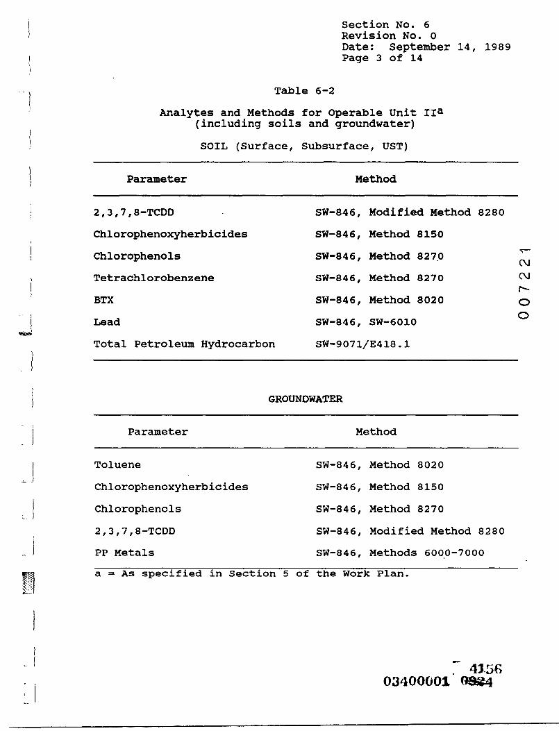
Section No. 6Revision No. 0Date: September 14, 1989Page 3 of 14
Table 6-2
Analytes and Methods for Operable Unit II3(including soils and groundwater)SOIL (Surface, Subsurface, UST)
Parameter Method
2,3,7,8-TCDD SW-846, Modified Method 8280Chlorophenoxyherbicides SW-846, Method 8150Chlorophenols SW-846, Method 8270 v ,Tetrachlorobenzene SW-846, Method 8270 <M
( --BTX SW-846, Method 8020 QLead SW-846, SW-6010Total Petroleum Hydrocarbon SW-9071/E418.1
GROUNDWATER
0
Parameter Method
Toluene SW-846, Method 8020Chlorophenoxyherbicides SW-846, Method 8150Chlorophenols SW-846, Method 82702,3,7,8-TCDD SW-846, Modified Method 8280PP Metals SW-846, Methods 6000-7000a = As specified in Section 5 of the Work Plan.
F" 4l5fi03400001 0884

Section No. 6' Revision No. 0Date: September 14, 1989Page 4 of 14
quality assurance, documentation and reporting procedures willbe in accordance with guidelines provided in the CLP. Formethods not included in the CLP, but described in SW-846 ( U . S .EPA, 1 9 8 6 ) , quality assurance, documentation and reportingprocedures will parallel those required for methods covered inthe CLP. For ASTM methods, the quality assurance procedureswill be those specifically described in the methods. Themethods to be used are the standard analyses in the industry.The quantitation limits for some compounds using these methodsPsIr~-may be higher than that necessary to estimate risk at theIxlO""6 level and will be used to support the risk assessment.
No standard method is available for analysis of 2,3,7,8-TCDDcollected by wipe or dust sampling. A simple extraction asdescribed in Verification of PCB Cleanup bv Sampling andAnalysis. EPA-560/5-85-026, August 1985c, may be used. Alter-nately, the samples may be extracted by Soxhiet ( U . S . EPA,SW-846 Method 3540) or by sonication ( U . S . EPA, SW-846 Method3550) with gas chromatographic - mass spectrometric analysis(Method 8 2 8 0 ) ( 1 9 8 6 ) .
Samples to be analyzed for BTX will be analyzed by a purge-and-trap method, ( U . S . EPA, SW-846 Method 5030) and followed bygas chromatography with photoionization detection ( U . S . EPA,SW-846 Method 8020). Alternatively, a purge-and-trap GC/MSmethod will be used to analyze BTX samples ( U . S . EPA, SW-846Method 8240) ( 1 9 8 6 ) .

Section No. 6Revision No. 0Date: September 14, 1989Page 5 of 14
Samples of transformer oil, if collected for analysis, will beextracted as described in The Determination of PolychlorinatedBiphenyls in Transformer Fluid and Waste Oils. EPA-600/4-81-045, followed by analysis with gas chromatographic-electron capture detection.
To avoid ambiguity in reporting results, it will be thepractice to use "significant figures" as described in Standard!^*
C\JMethods for the Examination of Water and Wastewater. 16th(-vJEdition, 1985, unless specifically noted.
06 . 2 METHOD QUANTIFICATION LIMITS
Tables 6-3, 6-4, and 6-5 provide the method quantificationlimits for compounds to be analyzed using the methods listed inTables 6-1 and 6-2. Quantitation limits are listed for water,soil, and organic liquid and solid matricies.
6 . 3 METHOD VALIDATION
In the event it becomes apparent that method performance ofsome samples ( e . g . , organic liquids/solids) does not meet theDQO^S for data usability then some alternative may need to bedeveloped and validated. In general, the validation processincludes:
. 415803400001 6

Table 6-3Target Compound List and Quantitation Limits for AnalysesPerformed in Accordance with CLP-SOW, Organic Analyses
Volatiles (Method 8240)
1.2.3.4.5.
6.7.8.9.
10.
11.12.13.14.15.
16.17.18.19.20.
21.22.23.24.25.
26.27.28.29.30.
Compound
ChloromethaneBromomethaneVinyl ChlorideChloroethaneMethylene Chloride
AcetoneCarbon Disulfide1,1-Dichloroethene1,1-Dichloroethanetrans-1,2-Dichloroethane
Chloroform1,2-Dichloroethane2-Butanone1,1,1-TrichloroethaneCarbon Tetrachloride
Vinyl AcetateBromodichloromethane1,1,2,2-Tetrachloroethane1,2-Dichloropropanetrans-l,3-Dichloropropane
TrichloroetheneDibroroochloromethane1,1,2-TrichloroethaneBenzenecis-1,3-Dichloropropane
2-Chloroethyl Vinyl EtherBromoform2-Hexanone4-Methyl-2-PentanoneTetrachloroethene
0Waterug/L
10101010
5
105555
55
1055
105555
55555
105
1010
5
uantitatjSoilug/kg
10101010
5
105555
55
1055
105555
55555
105
1010
5
Lon LimitsOrganicSolids
100100100100
50
10050505050
5050
1005050
10050505050
5050505050
10050
100100
50
aLiquids/mg/kg
^tC\JC\Jr-00
6-6 03400001 "oag^

Table 6-3(Continued)
Compound
31. Toluene32. Chlorobenzene33. Ethyl Benzene3 4. Styrene35. Total Xylenes
Semivolatiles method 8270)
3 6. N-Nitrosodimethylamine37. Phenol38. Aniline39. bis(2-Chloroethyl) ether40. 2-Chlorophenol
41. 1,3-Dichlorobenzene42. 1,4-Dichlorobenzene43. Benzyl Alcohol44. 1,2-Dichlorobenzene45. 2-Methylphenol
46. bis(2-Chloroisopropyl)ether
47. 4-Methylphenol48. N-Nitroso-Dipropylamine49. Hexachloroethane50. Nitrobenzene51. Isophorone52. 2-Nitrophenol53. 2,4-Dimethylphenol54. Benzoic Acid55. bis(2-Chloroethoxy) methane 10
56. 2,4-Dichlorophenol57. 1,2,4-Trichlorobenzene58. Naphthalene59. 4-Chloroaniline60. Hexachlorobutadiene
cWaterug/L
55555
1010101010
1010101010
101010101010101050
10101010
' 10
?uantitatjSoil^ug/kg
55555
330330330330330
330330330330330
330330330330330330330330
1,600330
330330330330330
LonOrgani
Soli
Limitsac Liquids/ds mg/kg
5050505050
100100100100100
100100100100100
100100100100100100100100500100
100100100100100
mC\JCMr~-00
6-7 416003400001 oagg
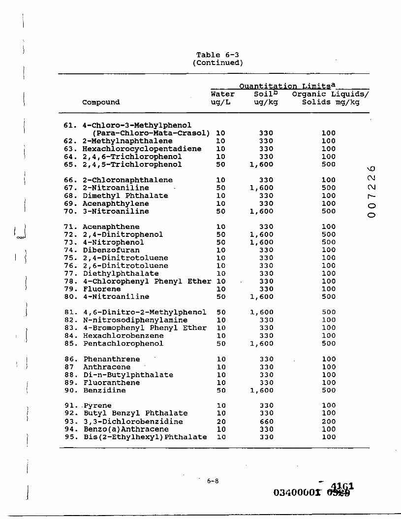
Table 6-3(Continued)
61.
62.63.64.65.
66.67.68.69.70.
71.72.73.74.75.76.77.78.79.80.
81.82.83.84.85.
86.8788.89.90.
91.92.93.94.95.
VCompound i;
4-Chloro-3-Methylphenol(Para-Chloro-Mata-Crasol)
2-MethylnaphthaleneHexachlorocyclopentadiene2,4,6-Trichlorophenol2,4,5-Trichlorophenol
2-Chloronaphthalene2-NitroanilineDimethyl PhthalateAcenaphthylene3-Nitroaniline
Acenaphthene2,4-Dinitrophenol4-NitrophenolDibenzofuran2,4-Dinitrotoluene2,6-DinitrotolueneDiethylphthalate4-Chlorophenyl Phenyl EtherFluorene4-Nitroaniline
4,6-Dinitro-2-MethylphenolN-nitrosodiphenylamine4-Bromophenyl Phenyl EtherHexachlorobenzenePentachlorophenol
PhenanthreneAnthraceneDi-n-ButylphthalateFluorantheneBenzidine
•PyreneButyl Benzyl Phthalate3,3-DichlorobenzidineBenzo(a)AnthraceneBis(2-Ethylhexyl)Phthalate
ratelig/L
1010101050
1050101050
10505010101010101050
5010101050
1010101050
1010201010
Ouantitation L.• Soil" Org<
ug/kg S(
330330330330
1,600
3301,600
330330
1,600
3301,6001,600
330330330330330330
1,600
1,600330330330
1,600
330330330330
1,600
330330660330330
imitsaanic Liquids/slids mg/kg
100100100100500
v0
100 (^500 CM100 r-100 o500 ^
100500500100100100100100100500
500100100100500
100100100100500
100100200100100
6-8
03400003; dtS&1

Table 6-3(Continued)
Compound
96. Chrysene97. Di-n-octyl Phthalate98. Benzo(b)Fluoranthene99. Benzo(k)Fluoranthene
100. Benzo(a)Pyrene
101. Indeno(l,2,3-cd)Pyrene102. Dibenz(a,h)Anthracene103. Benzo(g,h,i)Perylene
Pesticides /Method 8080)
104. Alpha-BHC105. Beta-BHC
106. Delta-BHC107. Gamma-BHC (Lindane)108. Heptachlor109. Aldrin110. Heptachlor Epoxide
111. Endosulfan I112. Dieldrin113. 4 ,4^-DDE114. Endrin115. Endosulfan II
116. 4 ,4^ -DDD117. Endrin Aldehyde118. Endosulfan Sulfate119. 4 ,4^-DDT120. Endrin Ketone
121. Methoxychior122. Chlordane12.3. Toxaphene
OlWaterug/L
1010101010
101010
0.050.05
0.050.050.050.050.05
0.050.100.100.100.10
0.100.100.100.100.10
0.50.51.0
lantitatjSoil^ug/kg
330330330330330
330330330
88
88888
816161616
1616161616
8080
160
Lon LimitsOrganic
Solids
100100100100100
100100100
1.21.2
1.21.21.21.21.2
1.22.42.42.42.4
2.42.42.42.42.4
1.21.2
24.0
aLiquids/mg/kg
r-C\JCMr-00
6-9

Table 6-3(Continued)
Quantitation Limits^Compound
Water Soil" Organic Liquids/ug/L ug/kg Solids mg/kg
124.125.126.127.128.129130.
Aroclor-1016Aroclor-1221Aroclor-1232Aroclor-1242Aroclor-1248Aroclor-1254Aroclor-1260
0000011
.5
.5
.5
.5
.5
.0
.0
8080808080
160160
55555
1010
•
•
•
•
•
•
•
0000000 00
C\J(Ma = Specific sample quantitation limits are highly matrix- i.^.
dependent. The quantitation limits listed herein are providecLfor guidance and may not always be achievable due to high —concentrations of target analytes or interterents in the 0samples. This will be especially true for the organicliquids/solids.
b = Quantitation limits listed for soil and organic solids arebased on wet weight. The quantitation limits calculated by thelaboratory for soil and organic solids, calculated on dryweight basis, will be higher.
6-10 G "" 416303400001 0^

Table 6-4
Inorganic Constituents and Quantitation Limits for AnalysesPerformed in Accordance with the CLP-SOW, Inorganic Analysis
_____Quantitation Limits^_____Water Soil" Organic Liquids/
Compound ug/L ug/kg Solids13 (ug/kg)
Inorqanics (Method 6000/7000 Series)AntimonyArsenicBariumBerylliumCadmiumCalciumChromiumCopperLeadMagnesiumMercuryNickelPotassiumSeleniumSilverSodiumThalliumZinc
. 6010
20055
5,0001025
55,000
0.240
5,0005
105,000
1020
12.2.
40.1.1.
1,002.5.1.
1,000.8.
1,001.2.
1,002.4.
000000000020000000
244
8022
2,0004
102
2,0000
162,000
24
2,00048
.0
.0
.0
.0
.0
.0
.0
.0
.4
.0
.0
.0
.0
.0
ONCMCMr-00
a = Specific sample quantitation limits are highly matrix-dependent. The quantitation limits listed herein areprovided for guidance and may not always be achievable.
b = Quantitation limits listed for soil and organic solids arebased on wet weight. The quantitation limits calculated bythe laboratory for soil and organic solids, calculated on dryweight basis, will be higher.
6-1103400001 -^&i^
^^w^^^

Table 6-5Method Quantitation Limits for 2,3,7,8-TCDD, Chlorophenols,
Chlorophenoxyherbicides, and Chlorobenzenes
Compound
____Quantitation Limits3_____W a t e r S o i l ^ O r g a n i c Liquids/ug/L ug/kg Solids13 (mg/kg)
Chlorinated Dioxins2,3,7,8-TCDD (Modified .005Method 8280)
Chlorophenols (Method 8270)2-Chlorophenol 104-Chlorophenol 102,4-Dichlorophenol 102,6-Dichlorophenol 102,3,6-Trichlorophenol 502.4.5-Trichlorophenol 502.4.6-Trichlorophenol 10Chlorophenoxvherbicides (Method 8150)2,4-Dichlorophenoxyacetic acid 1
(2, 4 - D )2,6-Dichlorphenoxyacetic acid® 12.4.5-Trichlorophenoxyacetic 0.50acid
2.4.6-Trichlorophenoxyacetic Iacid®
Silvex 2-(2,4,5-TP) 0.50Chlorobenzenes (Method 8270)Tetrachlorobenzene 10
0.3 0.003
330330330330
1,6001,600330
2020102010
330
100100100100500500100
lO'3-
IQt^5d
10^
5d
100
0^C\Jr^00
a = Specific sample quantitation limits are highly matrix-dependent. The quantitation limits listed herein areprovided for guidance and may not always be achievable.
b = Quantitation limits listed for soil and organic solids arebased on wet weight. The quantitation limits calculated bythe laboratory for soil and organic solids, calculated on dryweight basis, will be higher.
c = This quantitation limit is based on a Method 8280quantitation limit reported for more than 500 2,3,7,8-TCDDanalyses performed on Site soils by U . S . EPA. Actualquantitation limits are sample-specific and may vary from thelisted minimum quantitation limits due to variations assample size, dilutions, percent moisture, background noise,and matrix effects.
6-12 ^. 416503400001 oaaa

Table 6-5 (Continued)
d = The sample preparation method reference for analysis of thesecompounds in organic liquids and solids is not 8150. Themethod will utilize a 1 g sample aliquot dissolved in anappropriate solvent and analyzed using the same chromoto-graphic conditions as described in 8150.
e = These compounds are not routinely analyzed. An attempt willbe made to quantify these compounds. Method for herbicidesdoes not include procedure for organic solids/liquids. Datawill be QA'd by comparing with related compounds in samesample.
mCMr-00
6-13 03400001 ®^$
Draft - Do Not Cite or Quote Section No. 6Revision No. 0Date: July 30, 1989Page 14 of 14
• Selection of a method that is capable of producingmeasurements of the type and quality needed toaddress the DQOs;
• The verification that the method selected is based onsound technical principles; and
C\j• The method has been reduced to practice for practicalpurposes ( i . e . , U . S . EPA, CLP-SOW; U . S . EPA, SW-846C\1r"~or ASTM). ' 0
0
The initial method selection will be based on these measurementneeds.
Limited confirmatory testing to verify the method may need tobe performed. The primary purpose of confirmatory testing isto provide confirmation of the method performance. Theselaboratory tests would provide method information related to:
• Routinely achievable quantitation limits;• Useful dynamic range;• Typical spike recoveries in samples of interest; and• Accuracy and precision.
Such additional method validation procedures, if needed, willbe described to U . S . EPA in future correspondence and will beincluded in this QAPP by reference, if necessary.
03400001 ( 67

Section No. 7Revision No. 0Date: September 14, 1989Page 1 of 9
SECTION 7
RECORD KEEPING/DOCUMENTATION
7 . 1 PROJECT DOCUMENTATION mK\Records are the means by which an organization documents its1 -operations and activities. Records, final and revisedD
0documents, and information relating to the performance of thework pursuant to the Administrative Order will be preserved.This includes but is not limited to: sample analyses,chain-of-custody records, receipts, contracts, bills of lading,correspondence, and other documents produced during the work.
7 . 1 . 1 Protect Document Control
This Quality Assurance Project Plan will have the followinginformation on each page:
• Section number?
• Revision number; and
.. 416803400001 <[3i§^

Section No. 7Revision No. 0Date: September 14, 1989Page 2 of 9
Revision date.
Page number/total number of pages in the section.
When this document is revised, the affected pages will bereissued to applicable personnel listed as document holders
•^with updated revision numbers and dates. Issuance of revisions^
CMwill be accompanied by instructions as to which documents orportions of documents have been superseded. °
0
Control of, and accounting for the documents generated will beachieved by assigning the responsibility for document issuanceand archiving through Hercules.
7.2 LABORATORY DOCUMENTATION
Records are an integral part of the laboratory qualitycontrol program since they provide evidence that the analysishas been performed correctly and they provide the necessaryinformation for audits of an analytical process. The processof keeping records can be divided into three sections:internal record keeping, data reporting, and document control.
416903400001 08^

Section No. 7Revision No. 0Date: September 14, 1989Page 3 of 9
7 . 2 . 1 Internal Record Keeping
During the analytical process, certain essential data will bemaintained to document an analysis. This includes informationon the following laboratory related items:
• Sample receipt;• Sample tracking information;• Sample storage;• Sample extraction;• Instrument calibration;• Analysis;• Data review;• QC summary; and• Summary of analytical results.
Raw data, including chromatograms and standards data, will alsobe retained. .Data from an analysis or a set of analyses willbe maintained in a data package or in laboratory logbook(s).The data package and associated logbook(s) will contain theinformation necessary to reconstruct how the data from theanalysis of a batch of samples, including QC results, werederived. Entries will be made in ink, signed, dated, andfilled out by the preparer. Notes will be made if the informa-tion requested is non-applicable for the specific analysis orbatch. Errors will be corrected by making a single line
417003400001 Q9&S

Section No. 7Revision No. 0Date: September 14, 1989Page 4 of 9
through the error and initialing and dating the correction atthe time of the discovery of the error.
7 . 2 . 1 . 1 Sample Receipt
This is a record containing information about the samples whenthey were received by the laboratory. Items to be included^
m.CMr-o
• Data samples were received; 0
• Whether the samples were received in good condition;
• Whether they were chilled or at ambient temperature;
• Whether the chain-of-custody/sample analysis requestform(s) were present; and
• If the chain-of-custody seal(s) was intact.
This information is included on WESTO^s chain-of-custody formshown in Figure 4-1.
41710340000108 8

Section No. 7Revision No. 0Date: September 14, 1989Page 5 of 9
7 . 2 . 1 . 2 Sample Tracking Information
This will include, at a minimum, a copy of thechain-of-custody/sample analysis form(s), appropriate sampledigestion and extraction forms, and notes on subsequent uses ofthe sample in the laboratory.
r-7 . 2 . 1 . 3 Sample Storage Information ro
CMr -
This is a record of the sample storage conditions subsequent to0receipt in the laboratory. Sample storage information recordswill be maintained by the laboratory.
7 . 2 . 1 . 4 Sample Extraction Information
Sample extraction records will describe the extraction processand include the analyses initials, date of extraction andsample weights or volumes. A record of dilutions, ifperformed, and observations about the sample will also beincluded, when applicable.
7 . 2 . 1 . 5 Instrument Calibration
Instrument calibration records will contain the results of theinitial calibrations of the instrument used in the analysis aswell as a record of the results obtained from the analysis of
1" 417203400001 6340

Section No. 7Revision No. 0Date: September 14, 1989Page 6 of 9
continuing calibration standards which are analyzed as speci-fied in the calibration procedures described in Section 5. Therecords will include the calculated percent difference betweenthe average response factor from the initial calibration andthe continuing calibration check standard.
7 . 2 . 1 . 6 Analysis Data Sheet 00l tCM
The analysis data sheet is a report of the sample analysis.1""1'0
Information which will be provided on this sheet includes:osample number, matrix type, sample weight or volume, datereceived, date extracted, date analyzed, and concentrationsfound.
7 . 2 . 1 . 7 Copies of Chromatograms
Copies of chromatograms generated during organic analyses,including QC samples, will be provided and maintained.Chromatographic peaks will be labelled. Chromatographic peaksof standards will also be labelled. Retention times and peakareas or heights, date, time and amount of injection, GC columnidentification and GC instrument identification will berecorded.
1 417303400001 QS^a.

Section No. 7Revision No. 0Date: September 14, 1989Page 7 of 9
7 . 2 . 1 . 8 Data Summary
The results of the analyses will be tabulated and included as aportion of the data package.
7 . 2 . 1 . 9 Raw QC DataCT
The raw QC data will include information on blanks, matrixspikes and duplicates, and instrument tuning and performance.r"'
0It may be tabulated as a summary. 0
7.2. 1 . 1 0 Laboratory Chronicle
This is a record which will be included in the data packagecontaining a summary of dates of sample receipt, preparation,and analysis.
7 . 2 . 2 Data Reporting
Full CLP packages will be supplied to the independent datavalidator and will be available to U . S . EPA upon request. Oncevalidated, data summary reports will be supplied to projectpersonnel. If questions occur during this review, the reportwill be re-routed to the Laboratory Project Manager forexplanation or clarification of the questions. When questionshave been resolved, the data will be reported. Items whichwill be included in the report of analysis are: a laboratory
03400001 ( S£?4

Section No. 7Revision No. 0Date: September 14, 1989Page 8 of 9
chronicle, data summary, and a QC summary. These items willcontain, at a minimum, the following information:
• Laboratory chronicle - a compilation of the samples/
progress through the laboratory delineating the dateof sample collection, receipt, extraction, andanalysis.
0t-
• Case Narrative - includes a descriptive account ofany unusual events encountered in the processing of0
0the samples or any corrective action taken as well asthe resolution of the problem. Abbreviations anddata reporting qualifiers used in the reporting ofthe data will also be defined here.
• Data summary - an accumulation of the analyticalresults for each batch of samples.
• QC summary - information on blanks, surrogates,matrix spikes and duplicates, and instrument tuningand performance.
7 . 2 . 3 Laboratory Document Control
Raw data, including chromatograms and standards data, will beretained. Data contained in laboratory logbooks such as
03400001 ($218"". 4175

Section No. 7Revision No. 0Date: September 14, 1989Page 9 of 9
instrument calibrations, reagent purity confirmations, andother documentation relevant to the analysis but not requiredfor reconstruction of the analytical process will be maintainedby the laboratory.
Data will be made available to the U . S . EPA at the place ofretention upon request. U.S. EPA may audit the performance ofthe laboratory in conjunction with the review of these records.^
CMr-
7 . 2 . 4 Field Sampling Document Control °
Raw field sampling data, including field logbooks, will be,retained. Other field sampling documentation relevant to theproject such as field instrument calibration but not requiredin reconstructing the sample location will also be maintained.
^ 417603400001 0 4

Section No. 8Revision No. 0Date: September 14, 1989Page 1 of 12
SECTION 8
DATA MANAGEMENT
8.1 FIELD AND TECHNICAL DATA
C\JThe field and technical (nonlaboratory) data that will be
CMcollected can generally be characterized as either "objective"or "subjective" data. °0
Objective data include direct measurements made in the fieldsuch as well depths, grid measurements, and vessel dimensions.Subjective data include descriptions and visual observations.Some technical data, such as soil boring logs for instance,include both subjective and objective data in that the datarecorded in the field are descriptive but can be reduced usinga standardized lithologic coding system.
Field Logs
Data collection activities, including inventories and samplecollection, performed at the Site will be documented either ina field logbook or on appropriate forms or maps. Entries willbe detailed and descriptive so that a particular situation canbe recalled without reliance solely on the collector's memory.
- -C- -417703400001 8&4S

Section No. 8Revision No. 0Date: September 14, 1989Page 2 of 12
Field log entries will be dated. Field logbooks will be boundbooks and will be assigned to individual field personnelperforming specified tasks. Field log forms will be kept inbinders assigned to individual field personnel for each task.
Each logbook or binder will contain the following information:
• Project name.• Task description.• Start date.• End date.
8 . 1 . 1 Data Reduction
mi-
(Mr"-o0
As described in Section 6 . 1 , field data will be recorded byfield personnel in bound field logbooks and on the appropriateforms in binders. For example, during drilling activities, thefield team member supervising a rig will keep a chronologicallog of drilling activities, a descriptive log of lithologiesencountered, other pertinent drilling information (staining,odors, field screening, atmospheric measurements, water levels,geotechnical data), and a labor and materials accounting in thebound logbook. Upon completion of each test boring or monitorwell, a form in a binder will be completed that will includelithologic codes along with descriptive data.
_ 41^7803400001 4W6

Section No. 8Revision No. 0Date: September 14, 1989Page 3 of 12
After checking the data in the field notes and forms (Section6 . 1 . 2 ) , the data will be reduced to tabular form, whereverpossible, by entering it in data files. Where appropriate, thedata files will be set up for direct input into the database.For example, the form for a test boring or well log will bechecked against the field notes and then may be keypuncheddirectly into a database. Other objective data may be set uptin spreadsheet-type tabular files ( e . g . , water level data) .^
CVJSubjective data will be filed as hard copies for later review^.by the Engineering or Geological Manager(s) and foi"incorporation into technical reports, as appropriate.
8 . 1 . 2 Data Review
Review of objective field and technical data will be performedat two different levels. On the first level, data will bereviewed at the time of collection by review of the Field TeamLeader. At the second level, data will be reviewed at the timeof data reduction which will assure that the correct codes andunits have been included.
After data reduction into tables or arrays, the data will bereviewed for anomalous values. Inconsistencies or anomaliesdiscovered will be resolved immediately by the Engineering orGeological Manager(s), if possible, by seeking clarificationfrom the field personnel responsible for collecting the data.
417903400001 Oft^

Section No. 8Revision No. 0Date: September 14, 1989Page 4 of 12
Subjective field and technical data will be reviewed by theappropriate Engineering or Technical Managers who will checkfield reports for reasonableness and completeness. Inaddition, random checks of sampling and field conditions willbe made by the Quality Assurance Coordinator(s), who will checkrecorded data at that time to confirm the recorded observa-tions. Whenever possible, peer review will also be incor-,^porated into the data review process, particularly for subjec-(Mtive data, to maximize consistency among field personnel. Fort--
0example, during drilling activities, the Field Team Leader wilL-<,schedule periodic reviews of archived lithologic samples toassure that the appropriate lithologic descriptions and codesare being consistently applied by field personnel.
8 . 2 LABORATORY DATA INTERNAL PROCEDURES
8 . 2 . 1 Sample Log-in
The sample custodian, upon receipt of samples for analysisaccompanied by a completed request for analysis and/or chain-of-custody form, will do the following:
• Verify completeness of submitted documents, includingthe chain-of-custody forms.
~ 418003400001 9948

Section No. 8Revision No. 0Date: September 14, 1989Page 5 of 12
Log in samples, assign unique batch numbers, andattach the numbers to the sample container(s).
Open the project file and enter data on thelaboratory computer.
• Store samples in refrigerated sample bank.v01-
8 . 2 . 2 Analytical Data CMr--oData describing the processing of samples will be accumulatedin the laboratory and recorded in laboratory logbooks.Laboratory logbooks will contain the following:
Date of processing.Sample numbers.Client (optional).Analyses or operation performed.Calibration data.Quality control samples included.Concentrations/dilutions required.Instrument readings.Special observations (optional).Analyst's signature.
~L 438103/iOOOOl Q6SQQ

Section No. 8Revision No. 0Date: September 14, 1989page 6 of 12
8 . 2 . 3 Data Reduction
Data reduction is performed by the individual analysts andconsists of calculating concentrations in samples from the rawdata obtained from the measuring instruments. The complexity ofthe data reduction will be dependent on the specific analyticalI"-method and the number of discrete operations (extractions,"^
C\Jdilutions, and concentrations) involved in obtaining a sample^that can be measured. _0
For those methods using a calibration curve, sample responsewill be applied to the linear regression line to obtain aninitial raw result, which is then factored into equations toobtain the estimate of the concentration in the sample.Rounding will not be performed until after the final result isobtained to minimize rounding errors, and results will notnormally be expressed in more than two ( 2 ) significant figures.
Copies of raw data and the calculations used to generate thefinal results will be retained on file to allow reconstructionof the data reduction process at a later date.
03400001 S950..41Q2

Section No. 8Revision No. 0Date: September 14, 1989Page 7 of 12
8 . 2 . 4 Data Review
System reviews are performed at each level. The individualanalyst constantly reviews the quality of data throughcalibration checks, quality control sample results, andperformance evaluation samples. These reviews are performedprior to submission to the Laboratory Project Manager, oo
^(M
The Laboratory Project Manager will review data for the1""0
consistency and reasonableness with other generated data andodetermine if program requirements have been satisfied.Selected hard copy output of data (chromatograms, spectra,etc.) will be reviewed to assure that results are correctlyinterpreted. Unusual or unexpected results will be reviewed,and a resolution will be made as to whether the analysis shouldbe repeated. In addition, the Laboratory Project Manager willrecalculate selected results to verify the calculationprocedure.
The Laboratory QA Coordinator independently conducts a reviewof selected projects to determine if laboratory qualityassurance/quality control requirements have been met.Discrepancies will be reported to the appropriate LaboratoryProject Manager for resolution.
1" 418303400001 oast
Section No. 8Revision No. 0Date: September 14, 1989Page 8 of 12
The final routine review is performed by the Laboratory Managerprior to reporting the results to the client. Nonroutine auditsare performed by regulatory agencies and client representa-tives. The level of detail and the areas of concern duringthese reviews are dependent on the specific programrequirements.
c•^8 . 2 . 5 Data Reporting ^r—0
Reports will contain final results (uncorrected for blanks andC)recoveries), methods of analysis, levels of detection, surro-gate recovery data, and method blank data. In addition, specialanalytical problems and/or any modifications of referencedmethods will be noted. The number of significant figuresreported will be consistent with the limits of uncertaintyinherent in the analytical method. Consequently, most analyti-cal results will be reported to no more than two ( 2 ) signifi-cant figures. Data are normally reported in units commonly usedfor the analyses performed. Concentrations in liquids areexpressed in terms of weight per unit volume ( e . g . , microgramsper liter). Concentrations in solid or semisolid matrices areexpressed in terms of weight per unit weight of sample ( e . g . ,milligrams per kilogram).
;'. 43-8403400001 ea&a

Section No. 8Revision No. 0Date: September 14, 1989Page 9 of 12
Reported quantitation limits will be the concentration in theoriginal matrix corresponding to the low level instrumentcalibration standard after concentration, dilution, and/orextraction factors are accounted for, unless otherwise specifiedby program requirements.
The final data report provided for organic and inorganicanalyses by WESTON Analytics will conform to a full U . S . EPff
(MCLP report. r~~
00
8 . 2 . 6 Data Deliverable Package
Upon completion of the data reporting for a batch of samples, adeliverable package will be assembled for Hercules and U . S . EPAreview. The type and content of each deliverable package willdepend on the data objectives from the samples being analyzed.
The data deliverable packages for analyses of compoundsincluded in the U . S . EPA, CLP-SOW or U . S . EPA SW-846 willconform to requirements of the reporting requirements describedin the U . S . EPA, CLP-SOW.
1""418503400001 0^3

Section No. 8Revision No. 0Date: September 14, 1989Page 10 of 12
8 . 2 . 7 Data Archiving
The laboratories will maintain on file the raw data, laboratorylogbooks, and other documentation pertinent to the work on agiven project. This file will be maintained by WESTON for sixyears from the date of invoice unless a written request isreceived for an extended retention time.
inCMData retrieval from archives will be handled in a similar^
fashion as a request for analysis. Specifically, a written worg,request to include a quotation must be submitted for retrievalof data. Client confidentiality will be maintained withretrieved data. Consequently, the laboratory can honor onlythose requests for data authorized by the original client.
Data will be made available to U . S . EPA for a period of sixyears at the place of retention.
8 . 3 DATA VALIDATION/USABILITY REVIEW
Separate from the laboratory's internal data review/datavalidation, a review of the final data package will be per-formed to validate results and to determine usability. Criteriato assess usability will be taken from:
. 43LQ603400001 '08^4

Section No. 8Revision No. 0Date: September 14, 1989Page 11 of 12
U.S. EPA
Functional
Analyses.
HQ-8410-01
U.S. EPA
Functional
Analyses,
HQ-8410-01
U.S. EPA
i
•
/
•
/
1988C,
Guidelines
Technical
1988d,
Guidelines
Technical
1988e,
Laboratory
i for Evaluating
Directive
Laboratory
for Evaluating
Directive
Laboratory
Data
Document No.
Data
DOCUB
Data
Validation
Orcranic
Validation
Inoraanic
»ent No.
Validation
CMinCMr-00
Functional Guidelines for Evaluating Pesticides/PCBsAnalyses. Technical Directive Document No.HQ-8410-01.
Validation of data for analyses of compounds performed inaccordance with methods contained in U . S . EPA SW-846, but notincluded in the U . S . EPA CLP-SOW, will be performed usingsimilar validation guidelines to those used for CLP data.Analyses which will be validated using similar validationguidelines include:
Chlorophenols, Method 8270Chlorobenzenes, Method 8270Chlorophenoxyherbicides, Method 81502,3,7,8-TCDD, Modified Method 8280
-. 418703400001 0§§5

Section No. 8Revision No. 0Date: September 14, 1989Page 12 of 12
8.4 DATA REPORTING
Data once reviewed will be reported to U . S . EPA in accordancewith provisions in the Work Plan (Sections 4 . 9 and 5 . 7 ) .
8.5 DATA ARCHIVING ^LT\C\J
At the conclusion of this study, the files for this projects-CDwill be placed in "dead storage" at WESTON's West Chestero
office. Prior to this time, the files will be active and open.
"" 418803400001 ®8&6-

Section No. 9Revision No. 0Date: September 14, 1989Page 1 of 8
SECTION 9
INTERNAL QUALITY CONTROLS CHECKS
A quality control program is a systematic process that controlsthe validity of sampling and analytical results by measuring.^-
LT\the accuracy and precision of each method and matrix, develop-ing expected control limits, using these to detect anomalous^"
0events, and requiring corrective action techniques to preventoor minimize the recurrence of these events.
The accuracy and precision of sample analyses are influenced byboth internal and external factors. Internal factors are thoseassociated with sample preparation and analysis. Internalfactors are monitored by the use of laboratory quality controlsamples. External factors are associated with sample collec-tion. They are monitored by the use of field QC samples whichare identified as trip and field blanks.
This section describes the type of information provided by eachof the QC samples analyzed. Steps to be followed in thepreparation and spiking of samples are described in theanalytical methods referenced in Section 6 . The analyticalresults obtained from analyses of these QC samples will be usedto qualify results for field samples, where necessary.
0340000r ( ^

Section No. 9Revision No. 0Date: September 14, 1989Page 2 of 8
9 . 1 INTERNAL QUALITY CONTROL SAMPLES
9 . 1 . 1 Method (Reagent) Blank
The method (reagent) blank is used to monitor laboratorycontamination. This is usually a sample of laboratory reagentwater, treated with the reagents and in the same manner as theinsample ( i . e . , digested, extracted, distilled). One method^
04blank is prepared and analyzed with each batch of field sampler00
9. 1 . 2 Fortified Method (Reagent) Blank
Fortified method blank samples generally consist of thereagents used for a specific analysis, fortified with theanalytes of interest according to the appropriate analyticalmethod. They are prepared and analyzed with the associatedsample batch. The analyte recovery from each is used tomonitor accuracy of the analytical system and the duplicaterecovery values are used to monitor precision of the analyticalsystem. One fortified method blank will be analyzed for eachbatch of field samples.
9 . 1 . 3 Fortified Sample (Matrix Spiked
A fortified sample (matrix spike, MS) is an aliquot of a fieldsample which is fortified with the analyte(s) of interest and
41900340000X" 08s&—^^^^vJ

Section No. 9Revision No. 0Date: September 14, 1989Page 3 of 8
analyzed to monitor matrix effects associated with a particularsample. Duplicate fortified samples (matrix spike duplicate,MSD) will also be analyzed. One MS and MSD will be analyzedfor each chemical class of compounds, such as VOCs, BTX, BNAs,chlorophenols, chlorophenoxyherbicides, chlorobenzenes, or2,3,7,8-TCDD, in each batch of field samples. Matrix spikerecoveries will be used to assess the accuracy and precision of
vOthe laboratory chemical analyses in accordance with established^
CMranges (Table 9-1) and recoveries for matrix spike and matrix^spike duplicate will be used to assess the analytical preci^
0sion. If the recoveries or relative percent difference for aspecific sample fall outside these ranges, no sample reanalyseswill be performed unless it is clearly due to laboratory error.
9 . 1 . 4 Surrogates
Surrogates are organic compounds which are similar to analytesof interest in chemical composition, extraction efficiency, andchromatography, but are not normally found in environmentalsamples. These compounds are spiked into each standard, sampleblank, and fortified sample prior to analysis. Percentrecoveries are calculated for each surrogate. Surrogates willbe spiked into samples according to the appropriate analyticalmethod (Section 6 ) . Surrogate spike recoveries will fallwithin the control limits set in accordance with proceduresspecified in the method. Surrogate recoveries will not be
03400001 dSsS-

Table 9-1
QA Objectives for Precision ofLaboratory Chemical Analyses
Fraction
VOCVOCVOCVOCVOC
Matrix SpikeCompound3
1,1-DichloroetheneTrichlocoetheneChlorobenzeneTolueneBenzene
Recovery L i m i t s (X)Water Soil Organic6
61-145 59-172 60-17071-120 62-137 60-1*075-130 60-133 60-13076-125 59-139 60-15076-127 66-142 60-140
RPO L i m i t s (X)Water Soil Organic13
14 22 5014 24 5013 21 5013 21 5011 21 50
BN 1,2,4-Trichloro-benzene
BN AcenaphtheneBN 2,4-DinitrotolueneBN Di-n-butyl phthalateBN PyreneBN N-Nitroso-di-n-
propylamineBN 1,4-Dichlorobenzene
Acid PentachlorophenolAcid PhenolAcid 2-ChlorophenolAcid 4-Chloro-3-methyl-
phenolAcid 4-Nftrophenol
39- 98
4 6 - 1 1 824- 961 1 - 1 1 726-1274 1 - 1 1 6
38-107
3 1 - 1 3 728- 8929-13535-1424 1 - 1 2 6
40 -110
30-14030- 9030-14030-14040-130
28
3138403138
23
1947473638
50
5050505050
r"-LHCM("~-00
36- 97 28-104 30-100 28 27 50
9-10312- 8927-12323- 97
17-10926- 9025-10226-103
2 0 - 1 1 020- 9020-10030-100
50424042
47355033
50505050
10- 80 1 1 - 1 1 4 10 -120 50 50 50
Pest.Pest.Pest.Pest.Pest.Pest.
LindaneHeptachlorAldrinDieldrinEndrin4.4 ' -DOT
56-12340-13140-12052-12656-12138-127
46-12735-13034-1323 1 - 1 3 442-13923-134
40-13030-13030-13030-14040-14020-130
152022182127
503143384550
505050505050
PCB Aroclor 1254 Not Established6 50-150 30 50 50
Phenoxys 2,4-0Phenoxys 2 , 4 , 5 - TPhenoxys 2,4,5-TP
Not Established1' 25-132Mot Established6 27-116Not Established6 24-133
60b 60'' 6060'' 60b 6060l> 60'' 60
PCOD 2 , 3 , 7 , 8 - T C D D 60-140 60-140 60-140 50 50 50
The list provided includes those compounds most commonly used to fortifysamples based on current U . S . EPA Contract Laboratory Program and U . S . EPA,sw-846 Methods as identified in Tables 6-1 and 6-2.These recoveries and RPD l i m i t s are advisory only. They w i l l not be usedto determine if a sample requires reanalysis. These performance data werederived where available from the U . S . EPA CLP-SOW "Organics Analysis,M u l t i m e d i a , High/Medium Concentration" 4/85.
9-4 ~ 419203400001 0^9

Section No. 9Revision No. 0Date: September 14, 1989Page 5 of 8
calculated if sample dilution causes the surrogate concen-tration to fall below the quantitation limit. Surrogaterecoveries will be used to assess the accuracy of thelaboratory organic analyses in accordance with establishedranges (Table 9-2). Sample reanalysis criteria because ofunacceptable surrogate recoveries will be in accordance withthe requirements of applicable U.S . EPA SOW.
00inC\J9 . 1 . 5 Duplicate Field Samples ^00
Duplicate samples will be prepared by mixing the sample orcollecting sequentially a sample into two or more separatealiquots. Duplicate samples will be collected as specified inSection 3 . 1 1 . 2 . There will be one duplicate field sample foreach analyte in each batch of field samples.
9 . 2 OTHER INTERNAL QUALITY CONTROL CHECKS
In addition to the QC samples described in Section 9 . 1 ,additional independent types of quality control check sampleswill be routinely analyzed in the laboratory.
9 . 2 . 1 Laboratory Control Standard
A laboratory control standard is a solution with a certifiedconcentration which is analyzed as a sample and is used to
" " 419303400003T

Table 9-2QA Objectives for Accuracy ( % ) ofLaboratory Chemical Analyses
FractionSurrogateCompound^
Low/mediumWater Soil
Medium/HicrhOrgan ica
VOC Toluene-ds 88-100 81-117VOC 4-Bromo-fluorobenzene 86-115 74-121VOC l,2-Dichloroethane-d4 76-114 70-121VOC Bromchloromethane 60-140 40-130VOC o(, c<,o<-Trifluorotoluene 60-140 40-130BNA Mitrobenzene-ds 35-114 23-120BNA 2-Fluorobiphenyl 43-116 30-115BNA p-Terphenyl-di4 33-114 18-137BNA Phenol-ds 10- 94 24-113BNA 2-Fluorophenol 21-100 25-121BNA 2,4,6-Tribromophenol 10-123 19-122Pest. Dibutylchlorendate 24-154b 20-150bPCDD " 2,3,7,8-TCDD 60-140 60-140
50-16050-16050-160
0^inCM
20-149-.20-140^20-156^20-14?20-14010-14010-160
60-140
*These recoveries are advisory only.a - These recoveries are advisory only. They will not be used
to determine if a sample requires reanalysis. These perform-ance data were derived where available from the U . S . EPACLP-SOW "Organics Analysis, Multimedia, High/MediumConcentration" 4/85.
b - Since some of the organic samples have low pH, an alternatesurrogate to dibutylchlorendate may be used.
9-6 „ 419403400001 o&e%

Section No. 9Revision No. 0Date: September 14, 1989Page 7 of 8
monitor analytical accuracy. An appropriate frequency forrunning laboratory control standards will be based upon themethod and the specific analysis.
9 . 2 . 2 Blind Performance Sample
This is a QC sample of known concentration obtained from U . S .EPA, NBS, or commercial source and submitted for analysis by"0
CMthe Laboratory QA Coordinator. These samples are blind to the-~analyst and the results monitor analytical accuracy. Thes^samples are run by the laboratory as part of CLP and othercertifications but will not be specifically included in theanalytical program for the Site.
9 . 2 . 3 Known Performance Samples
These are obtained from the same sources as those described in9 . 2 . 2 except that the analyst uses these to check the accuracyof an analytical procedure prior to analysis of any samples.These are particularly applicable when a minor revision hasbeen made to an analytical procedure or instrument and will not
be specifically included in the analytical program for theSite.
" 419503400001 os 3

Section No. 9Revision No. 0Date: September 14, 1989Page 8 of 8
9 . 3 FIELD BLANKS
These samples are not included specifically as laboratoryquality control samples but are routinely analyzed whensubmitted. Data for these QC samples are reported withassociated samples. Field blanks are specifically discussedand will be collected as specified in Section 3 . 5 . Analyticalresults of the field blanks will be used to assess the
C\Jintegrity of the field samples during collection, handling, and -shipping. ^
9 . 4 PC MONITORING
Unless otherwise indicated, the analyses of laboratory qualitycontrol samples will be tabulated chronologically and enteredonto a quality control chart specifically maintained for eachanalytical procedure. These control charts will be labelledwith upper and lower warning limits, the analysis which isbeing charted and the value ( i . e . , concentration, precision,accuracy) which is being monitored. Control charts will beupdated monthly and will be used to demonstrate methodperformance and help identify system anomalies.
_ 419603400001 .Q»64
Section No. 10Revision No. 0Date: September 14, 1989Page 1 of 6
SECTION 10
PERFORMANCE AND SYSTEM AUDITS
10.1 GENERAL
CMEvaluation or assessment activities, known as audits, provide aC\Jmechanism for both a qualitative and a quantitative review off"-
0the project to assure that the data generated are of acceptable-^quality with respect to accuracy, precision, completeness,representativeness, and comparability. Audits take the form ofsystem or performance audits. System audits provide an onsiteinspection and an overall review of the quality controlsystems. Performance audits constitute an evaluation of thedata produced and are considered a check on the performance ofthe laboratory analysts. Audits will be performed usingcriteria given in this QAPP as the basis for the audit andstandard for comparison.
10.2 INTERNAL SYSTEM AUDITS
10.2.1 Field Audits
An audit of the field activities pertaining to conformancewith -QA/QC procedures described in this QAPP may be performedby designated WESTON personnel. ~ /11Q>-»
034000010 5

Section No. 10Revision No. 0Date: September 14, 1989Page 2 of 6
Items to be audited will include:
Review reference to or incorporation of acceptedsampling techniques in the Work Plan;
Review procedures for documenting and justifying anyfield actions contrary to this QAPP;
\0C\JReview pre-field activities such as equipment^.
check-out, calibrations, container storage an€r
preparation, and associated documentation;
Review documentation of field activities includingfield logbooks;
Observe field sampling including cleaning procedures;
Review post-field activities such as sample shipmentand receipt, field team debriefing, equipmentcheck-in, and associated documentation;
Review results from field blanks, sampling equipmentblanks, and trip blanks; and
Review documentation of training and experience for
field sampling technicians, where applicable.Z. 4198
03400001 0866

Section No. 10Revision No. 0Date: September 14, 1989Page 3 of 6
10.2.2 Laboratory Audits
An audit of laboratory activities pertaining to conformancewith QA/QC procedures described in this QAPP may be performedby designated WESTON personnel.
Items to be audited may include:
• General laboratory facilities;
• Instrumentation;
• Data handling and review;
• Record keeping;
• Quality Control Manual and documentation; and
• Laboratory performance in external evaluationprograms.
A written report on the results of the audit and nonconforroancenotification, if necessary, will be issued.
419003400001" 09^

Section No. 10Revision No. 0Date: September 14, 1989Page 4 of 6
10.3 INTERNAL PERFORMANCE AUDITS
Internal laboratory evaluation programs provide a means ofdetermining the quality of a laboratory's work. Externalevaluation programs provide an objective means of assessing theoverall effectiveness of the quality control through the use ofperformance evaluation samples. A written report on ther\results of the audit and nonconformance notification, inecessary, will be issued. r"'
00
10.4 EXTERNAL SYSTEM AUDITS
10.4.1 Field Audits
Independent audits of field sampling, preservation, shipping,and equipment cleaning procedures conducted by U . S . EPA ortheir representatives during the course of the project.Audits, if conducted, will be during actual field operationsand will use the criteria given in this QAPP as the basis forthe a^idit and standard for comparison.
After such an audit has taken place, the auditor will berequested to brief the Field Team Leader to discuss anynonconforming actions or procedures observed. A written reporton the results of the audit and nonconformance notification, ifnecessary, will be issued.
r 420003400001 W

Section No. 10Revision No. 0Date: September 14, 1989Page 5 of 6
WESTON Analytical Laboratories is currently evaluated throughperiodic, external system audits, listed in Table 10-1, inaccordance with various certifications maintained by thelaboratory.
10.4.2 Laboratory System Audits 0v0CM
U . S . EPA or their representatives may perform independent""0
audits of the laboratory activities instrumental in generatingDdata required by this QAPP. These audits may be similar tothose described in Section 1 0 . 2 . 2 . A written report on theresults of the audit and nonconformance notification, ifnecessary, will be issued.
10.5 EXTERNAL PERFORMANCE AUDITS
U . S . EPA or their representatives may perform independentexternal performance audits of laboratory generated data, attheir discretion. A written report on the results of the auditand nonconformance notification, if necessary, will be issued.
WESTON Analytical Laboratories is currently evaluated throughperiodic, external performance audits, listed in Table 10-1, inaccordance with various certifications maintained by thelaboratory.
». ^)1
03400001 OSfe&9

Table 10-1
Summary of External Performance and Systems AuditsUESTON Analytical Laboratories'
Agency
I l l i n o i s EPA
NY Departmentof Health
NY State Depart-ment of EnergyConservation
NJ Departmentof EnvironmentalProtection
Oklahoma WRB
PA OepartMent ofEnvironmentalResources
U.S. EPA
•
U.S. Army Corpsof Engineers
Parameters
US/MP
US/UP
Inorganic/Organic TCL
US/UP
Haz . Waste
WS/UP
us
Haz. Uaste
Inorganic /Organ ic TCL
Inorgan ic /Organic
Type
PerformanceSystem
Performance
PerformanceSystem
PerformanceSystem
Performance
Performance
PerformanceSystemPerformance
PerformanceSystem
PerformanceSystem
Frequency
Semi annually
Semi annually
EPA CLP Qtrly.Blind
Annua11yEvery two years
EPA CLP Q t r l y .
Semiannually
AnnuallyEvery 2 yearsEPA CLP Qtr ly.
Quar te r lyEvery two years
As contractrequires
Purpose
Water/Uastewater Cert.
Uater/Uastewater Cert.
State A n a l y t i c a l Contract
Uater/Uastewater Cert.
Haz . Uaste Approval
Uater/Uastewater Cert .
Water Cert.
State Ana ly t i ca l Contract
Superfund Re l a t edA n a l y t i c a l work
Uater /Uas tewater , Super-fund A n a l y t i c a l Work
r"-
(Mr-00
a - This is not an exhaustive list but is representative of major audit activities of WESTON'slaboratories.
US- Water Supply (Drinking Water).WP- Water Pollution (Wastewater).
Last on-site by U . S . EPA was performed in Hay 1989 in UESTON Lionville and Stockton labora-tories. Last PAOER on-site was performed in May 1987, and last IEPA on-site was performedin September 1988.
10-6
4202fMjhtri*"».— CT^^yr?

Section No. 11/ Revision No. 0Date: September 14, 1989Page l of 6
SECTION 11
PREVENTIVE MAINTENANCE
11.1 GENERAL EQUIPMENT MAINTENANCE AND REPAIR
00Instruments will be maintained in accordance with manufac-^0
CMturer^s specifications. More frequent maintenance may be,^.dictated depending on operational performance. Instrument logs—0will be maintained to document the date and type of maintenanceperformed.
Contracts on major instruments with manufacturers and serviceagencies will be used to provide routine preventive maintenanceand to ensure rapid response for emergency repair service.Minimal instrument downtime should be experienced through theuse of these contracts.
11.2 FIELD EQUIPMENT
An inventory control system governing field equipment andinstrumentation will be maintained by the equipment storeroomsupervisor as the basis for maintenance and calibrationcontrol. The inventory control documentation includes thefollowing:
4!?0303400001 0 1

Section No. 11Revision No. 0Date: September 14, 1989Page 2 of 6
Description of instrument.
Manufacturer, model number, and serial number.
Identification number.
cName, address, and telephone number of company that
CMservices the instrument or equipment, (s-
00
Type of service policy.
• Timing and frequency of routine maintenance, servic-ing, and calibration.
11.3 LABORATORY EQUIPMENT
11. 3 . 1 Introduction
The ability to generate valid analytical data requires thatanalytical instrumentation be properly and regularlymaintained. The WESTON Analytical Laboratory maintains fullservice contracts on each major instrument. These servicecontracts not only provide routine preventative maintenance butalso emergency repair service. The elements of the maintenanceprogram are discussed in the following sections.
420403400001 WfZ

Section No. 11Revision No. 0Date: September 14, 1989Page 3 of 6
11.3.2 Instrument Maintenance Logbooks
Each analytical instrument is assigned an instrument logbook.Maintenance activities are recorded in the instrument logbook.The information entered in the instrument logbook includes:
1. date of service,02. person performing service, l _
3. type of service performed and reason for service, (^-4. replacement parts installed (if appropriate), and 0
05. miscellaneous information.
If service is performed by the manufacturer, a copy of theservice record is taped into the page facing the logbook pagewhere the above information is entered.
11.3 . 3 Instrument Calibration and Maintenance
The routine calibration procedures and for analytical instru-mentation are described in Section 5 and shown in Table 11-1.Preventive maintenance and calibration by manufacturer servicerepresentatives are provided on a routine basis.
The maintenance procedures and frequencies for major analyticalinstrumentation are given in Table 11-2.
,. 4^0503400001 OQS3

Section No. 11Revision No. 0Date: September 14, 1989Page 4 of 6
TABLE 11-1CALIBRATION FREQUENCY AND MECHANISM FOR MAJOR INSTRUMENTS
Instrument
GC/MS
CalibrationFrequencyDaily (or every12 hours)
GC (Hall, PID, EC, Daily (or moreNPD, FID, FPD) frequently as
required)
HPLC
AA
ICP
ICP
Daily
Daily (or morefrequently)
Daily (or morefrequently)
Daily (or morefrequently)
Ion Chromatograph Daily
, Spectrophotometers Daily
Autoanalyzer Daily
Conductivity Meter Daily
Analytical Balance Daily, whenused
Ovens Quarterly
StandardStandard solutionof analytes to bemeasuredStandard solutionof analytes to bemeasuredStandard solutionof analytes to bemeasuredStandard solutionof analytes to bemeasuredInterelementInterferenceCheckStandard solutionof aniaytes to bemeasuredStandard solutionof analytes to bemeasuredStandard solutionof analytes to bemeasuredStandard solutionof analytes to bemeasuredStandard solutionof analytes to bemeasuredClass S weights(NBS Certified)NBS Thermometer
ParametersResponse/Sensitivity
RetentionTime/Response/SensitivityRetentionTime/Response/SensitivityResponse/Linear Range
WavelengthInterference
Response/T.inoa-r Range
RetentionTime/Response
Response/Linear Range
Response/Linear Range
Response
Accuracy
Accuracy
03400001 OsS 06

Section No. 11Revision No. 0Date: September 14, 1989Page 5 of 6
TABLE 11-2
LABORATORY INSTRUMENT MAINTENANCE SCHEDULE
Instrument
Gas Chromatograph/Mass Spectrometer
Gas Chromatographs
GC Detectors (FID, EC, ELD, Hall, NPD, FPD)
High Performance Liquid Chromatographs (HPLC)
Atonic Absorption Spectrometer (AA)(Flame and Furnace)
Inductively Coupled Plasma Spectrometer (ICP)
Analytical Balance
Ion Chromatograph
Spectrophototneters
Cold Vapor Mercury AA
Autoanalyzer
Conductivity Meter
Ovens
pH/Specific Ion Meter
PreventiveMaintenance
Semi-annually
Semi-annual ly
a
a
Semi-annually
Semi-annually
Annually
Annually
a
a
a
a
a
a
ServicOpPtca
Yes
Yes
Yes
No
Yes
Yes
Yes
Yes
No
No
No
No
No
No
eict
CM(---CMr-~00
Notes:a = As needed based on method and instrument performance criteria as determined
by the method.
^ 4^0703400001 f?9S5

Draft - Do Not Cite or Quote Section No. 11Revision No. 0Date: July 30, 1989Page 6 of 6
WESTON service agreements provide for preventative maintenance,emergency service, and emergency shipping of spare parts. Foremergency response, service contracts on the Gas Chromato-graphs, GC/MS instruments and AA-ICP require on-site responsewithin 48-72 hours. (Typically, service representatives are onsite within 24 hours of a service call.) The service contractsalso provide for 24-hour delivery of critical spare parts inresponse to a service request, t"-
C\Jr-
11.3.4 Spare Parts °
WESTON Laboratory maintains an inventory of routinely requiredspare parts (for example, spare sources, vacuum pumps andfilaments for GC/MS, spare torches, burner heads for AA-ICP).
The instrument operators have the responsibility, with theappropriate Section Manager, to ensure that an acceptableinventory of spare parts is maintained.

Section No. 12Revision No. 0Date: September 14, 1989Page 1 of 9
SECTION 12
SPECIFIC ROUTINE PROCEDURES FOR ASSESSING DATA QUALITY
12.1 GENERAL BACKGROUND
< -Some of the factors that affect data quality have been *
C\Jdescribed in other sections of this QAPP as follows: p .
00
• Data quality objectives (Section 1 ) ;
• Quality assurance mechanisms (Sections 2 , 13, 1 4 ) ;
• Sample collection (Section 3 ) ;
• Documentation and record keeping (Sections 4, 7 , and11) ;
• Internal quality control checks, including the use ofcontrol samples and control charts for evaluation ofaccuracy and precision (Sections 5, 6 , - a n d 9 ) ; and
• External quality control audits, including systems,performance, and data audits (Section 10).

Section No. 12Revision No. 0Date: September 14, 1989Page 2 of 9
This section is intended primarily to address quality assurancerequirements for the statistical processing and analysis ofreported data values. The reported data may go through severaldata processing steps, such as acquisition, entry, transfer,and storage in a database, before being analyzed to makestatistical estimates or to test hypotheses, .p.
r~-C\J
Reported data from the field, laboratory, and cartographic0sources will be validated at the respective data-generating^
sources before the data may be accepted. If the data areentered into a database, they will be further verified forconsistency with the originally recorded or reported valuesbefore they are subjected to statistical analysis.
12.2 CRITERIA FOR ACCEPTANCE OF DATA
12.2. 1 Acceptable Data
Several criteria will be used to determine the acceptability orqualification of data within a database. These may include butare not limited to:
• Conformance to applicable data collection forms;
• Presence of proper sample identification;Z 4 10
03400001 WW
Section No. 12Revision No. 0Date: September 14, 1989Page 3 of 9
Presence of documentation of chain-of-custody;
Relevancy of data with respect to DQOS;
Absence of obvious errors;v0r--
Comparability of data sets; and C\J(^-0
Consistency in unit of expression, for example: >
- mg/L for water samples- mg/Kg (ppm) for organic liquid/solid, soil, anddust samples.
- ug/2,500 cm2 for 2,3,7,8-TCDD in wipe samples.
In addition, "acceptability" of data will be assessed in termsof the data quality objectives as defined in Sections 1 . 4 , 6 ,and 9 . Data which meet the criteria listed above will beconsidered acceptable and may be qualified in accordance withU . S . EPA functional guidelines (Section 8 . 3 ) . Acceptabilitywill also be based upon advice to the Project Manager anddiscussions with the U . S . EPA Project Manager.

Section No. 12Revision No. 0Date: September 14, 1989Page 4 of 9
1 2 . 2 . 2 . Unacceptable Data
Any data that do not meet the criteria described under Section12.2,1 will be classified as "unacceptable" and thereforecannot be considered "verified" for certain data analyses.
Data may be unacceptable without being invalid. A judgement of^r-the sufficiency of data requires an evaluation of thec\J
I-*-availability and adequacy of the data record.0
12.2.3 Historical Data
U . S . EPA has accepted all data generated by U . S . EPA on theVertac Site as validated and acceptable for purposes ofcompleting the project (personal communication, M . S . Ramesh -U . S . EPA, August, 1 9 8 9 ) . Other historical data that existprior to the effective date of this QAPP may be accepted onlyif they meet the same criteria as defined in Section 1 2 . 2 . 1 forthe data to be strictly comparable. Historical data will bequalified in accordance with appropriate functional guidelines( U . S . EPA, 1988c, d, and e) and may be used as a guide inestablishing the sampling plan for the Site. Historical datawhich indicates contamination will be assessed using criteriaincluded in this QAPP and additional sampling, if any, will bebased upon negotiations with the U . S . EPA Project Manager.
. 4?"r03400001 0980

Section No. 12Revision No. 0Date: September 14, 1989Page 5 of 9
Separate files (aside from the verified) will be used to retainthe ^invalidated or unverified historical data which may be ofuse to the investigative program.
12.3 PROCEDURES FOR DETERMINING DATA QUALITY
12.3.1 Statistical Analysis 00r-CM
For application in the site characterization, determination ofthe mean or the range of parameter concentration values fo£>samples taken from a particular location has major significanceonly when compared to the environmental quality standards forthat parameter. However, from a practical standpoint, any testof hypothesis about the sample mean has little significancewith respect to data quality since the population mean ofparameter concentration values at a specific sampling locationis rarely fixed or known. Therefore, the variability of a dataset and the significance of extreme values which may bereported by analytical laboratories (after passing the routinequality control procedures with respect to data qualityobjectives for accuracy and precision) will be evaluated.
In order to adequately apply statistical analysis, themethodology presented below will be used for a set of data ifthe following assumptions are met:
-I 4 1303400001 eso
Section No. 12Revision No. 0Date: September 14, 1989Page 6 of 9
• Samples were taken within a reasonable period of timeduring which conditions were unchanged.
• Samples for the data set were taken from the samesampling point at random (to avoid the possibility ofbias).
0r-The statistical method used to evaluate the variability of a/\j
data set involves the calculations of the sample mean and0standard deviation. Both "normal distribution" andO"logarithmic normal distribution" will be tested for fitness,but only one will be chosen and so indicated in the report.
For a data set of normal distribution, the following equationswill be used:
X = (£Xj.)/nS = (((^Xi 2) - C2:Xi)2/n)/(n - 1 ) ) 0 . 5
Where:n = Number of samplesXi = Individual sample observation (i = 1, 2 , . . . , n)X = Sample meanS = Sample standard deviation
-., 421403400001 ®2
Section No. 12Revision No. 0Date: September 14, 1989Page 7 of 9
For a data set of logarithmic normal distribution, thefollowing equations will be used:
log Xg = (^.log Xi)/nlog Sg = (((-S(log Xi)2) - (^log Xj.)2/n)/(n - 1 ) ) 0 . 5
Where:Xg = Sample logarithmic (or geometric) mean
0Sg = Sample logarithmic (or geometric) standard deviation^CM
Data outside of two ( 2 ) standard deviations from the mean will I^"0be flagged. 0
For normal distribution:
(X ± 2S)
For logarithmic normal distribution:
Antilog of (log Xg ± 2 log Sg)
It is possible that some of these extreme values could still belegitimate and valid. They should be examined and interpretedcarefully by the technical staff.
The above statistical methods will not be applied to data setsfor samples whose analytical results are unrelated and a clearrationale exists for further separating the data set intorelated parts. More sophisticated software packages may be
1,4?1503400001 903

Section No. 12Revision No. 0Date: September 14, 1989Page 8 of 9
used to provide interrelated statistical and least squareanalysis and to plot the results on a map to show the contourof concentration distribution.
12.3.2 Data Completeness
To comply with the completeness requirements, routine checking"CD
procedures will be implemented to assure that no fewer then 15 \Jr~~of the samples collected and selected for analyses are analyzed^
and considered as "verified". °
In addition, "data sufficiency" will be considered in the sensethat sufficient data are needed to confirm the conceptualmodel, risk assessment or remedial design to a desired level ofconfidence. Data sufficiency will be achieved throughcollection of enough data to acquire a valid data set that willallow identification of existing and potential environmentalproblems with a high degree of confidence. Data sufficiency oradditional data needs will be evaluated by appropriatetechnical staff.
1 2 . 3 . 3 Data Tracking
A data tracking system will be provided to serve the followingfunctions:
4!?!l603400001" OSS4

Section No. 12Revision No. 0Date: September 14, 1989Page 9 of 9
Analytical data within the database will be readilytraceable to the original data by the sampleidentification number.
The chain-of-custody for samples and the status ofrequired data from field, laboratory, and cartographicsources will be readily traceable.- CD
CMr~00

Section No. 13Revision No. 0Date: September 14, 1989Page 1 of 16
SECTION 13
FEEDBACK AND CORRECTIVE ACTION
13.1 QUALITY ASSURANCE MANAGEMENTm00A quality assurance program is an assemblage of management^
policies, objectives, principles, and general procedures whichoutline how data of known and accepted quality are produced. 0
Quality assurance is attained through utilization of amanagement system that contains mechanisms to monitor andregulate its performance so that the present standards ofquality are maintained and that DQOs are met. This monitoringis accomplished through feedback mechanisms consistingprimarily of audits, corrective action procedures, and reportsto management.
Quality assurance audits are a key mechanism for ensuring thetechnical and procedural accuracy of project results. Auditsto be conducted as part of the quality assurance program mayinclude system audits, performance audits, and data audits.The individual functions for these types of audits aredescribed in the following sections. Corrective actionprocedures will be implemented when nonconformances or
Z, 4 1803400001 OQ©6

Section No. 13Revision No. 0Date: September 14, 1989Page 2 of 16
deficiencies are identified during a formal audit or duringother routine feedback mechanisms.
13.2 AUDITS
13.2.1 Responsibility. Authority, and Timing•^coQuality assurance audits to be conducted for the project may \jf>«.include system, performance, and data audits. Audits will be
conducted at appropriate times and intervals so as to maintainOquality. The audits may be conducted more frequently for aspecific task or activity. The Project QA Coordinator(s) willkeep on record a tentative schedule that lists the number andtypes of internal audits, both scheduled and unscheduled and acurrent list of the dates of completed audits. U . S . EPA ortheir representatives will be responsible for initiatingexternal audits.
Audits will be conducted by teams that consist of, at aminimum, the Audit Team Leader and the Auditor, who will havedirect responsibility for the audit. The Audit Team Leaderwill be responsible for the activities of a specified auditincluding organization, implementation, completion, andreporting. The audit team may also include a technicalassistant who will provide technical expertise and assistanceto the team on a specific task or function. r 4 19
03400001 e^

Section No. 13Revision No. 0Date: September 14, 1989Page 3 of 16
Specific audits will be planned, organized, and clearly definedbefore they are initiated. Procedures for the auditingactivities will be identified prior to implementation of theaudit, and will be designed to meet requirements for thespecific audit. In general, auditor(s) will identifynonconformances or deficiencies, report and document them,initiate corrective action through appropriate channels, and follow up with a compliance review. CM
1 -0
Records will be kept of auditing tasks and findings, o
13.2 . 2 Reports and Distribution
Following each internal system, performance, or data audit, areport will be prepared to document the findings of thespecific internal audit. In general, the format of theinternal audit quality assurance reports will consist of thefollowing:
• Description and date of audit;
• Name of Auditor;
• Copies of completed, signed, and dated audit form(s)and/or checklist;
^ 4^2003/S00001 08^8

Section No. 13Revision No. 0Date: September 14, 1989Page 4 of 16
• Summary of findings of the audit including anynonconformances or deficiencies;
• Where appropriate, photographs to further illustratesituations;
• Specific distribution list; 0COC\Jr»~• Date of report and appropriate signatures; and0
• . Description of corrective action, if necessary.
A signed and dated report on each audit will be maintained inthe project files.
1 3 . 2 . 3 Forms and Checklists
A form or checklist may be completed during each internalaudit. Audit forms or checklists will be prepared usingrequirements of this QAPP. At a minimum, the checklists willallow space for the following information:
• Date and type of audit;
• Name and title of Auditor;
_ 4 2103400001 o»89

Section No. 13Revision No. 0Date: September 14, 1989Page 5 of 16
Description of task or facility being audited;
Name(s) of lead technical personnel present at audit;
• Checklist of audit items according to scope of audit;and,
r-oo• Deficiencies or nonconformances. OJIs-0
13.2.4 System Audits 0
A system audit is an overall evaluation of components of theprogram^s data acquisition and management system to determinethat the program meets quality assurance standards throughproper design. This audit will entail checking of the projectfiles and documentation relating to both field and laboratoryquality control procedures. System audits may include, but arenot limited to, review and/or evaluation of the followingfactors:
• Technical personnel conducting the project;
• Project management structure;
• Reports and other documentation including chain-of-custody;
422203400001 ©a^.

Section No. 13Revision No. 0Date: September 14, 1989Page 6 of 16
Field and laboratory logbooks;
• Calculations;
Field and laboratory protocols;
• Data entry; and 0000C\J
• Training records and health and safety records.0
13.2.5 Performance Audits
The objective of a performance audit is to determine theaccuracy of the projects total measurement system or of itscomponents through evaluation of the field and laboratoryactivities related to data generation. This audit, whenconducted, will be performed by an audit team that goes to thefield (or office) and observes that the procedures beingfollowed are in accordance with this QAPP and that proper QCmeasures are being performed. Performance audits may include,but are not limited to, observation, review, and/or evaluationof the following factors:
• Execution of the field or laboratory data generationtasks such as sample collection, sample custody, andlaboratory procedures including use of performanceevaluation samples;
r\Ti r»r»r>r»-» 4^2303400001 088.1

Section No. 13Revision No. 0Date: September 14, 1989Page 7 of 16
Compliance with the field and laboratory analysisprotocols; and
• Performance of internal quality control checks thatare utilized within the sampling and analysis processor task; ^
00(N1-Performance audits may be conducted in separate segments to
cover field and laboratory activities. 0
13 . 2 . 6 Data Audits
The objective of a data audit is to ensure that systematicerror are not being introduced into the data during datameasurement, processing, or analysis procedures. Data auditstrace from generation of raw data at the laboratory analysisstep, through the data processing steps including computer datafiles and generation of reported data and data presentation.An internal data audit may include, but is not limited to,quantitative evaluation of the following items based on arandom selection of a few samples:
• Field sample logbooks and chain-of-custody records 7
• Raw data results from laboratory analyses?
03400001 Q99Z_ 4224

Section No. 13Revision No. 0Date: September 14, 1989Page 8 of 16
• Data from laboratory data summary sheets;
Computer data files;
Final data displays and summarizes (such as samplingresult reports) or parameter estimates based on thedata; and Oslr~-
oRoutine quality control reviews of data packages.
1 3 . 2 . 7 Feedback Mechanisms
In addition to formal audits, mechanisms exist within theproject structure that allow for identification, feedback, andcontrol of any nonconformances or deficiencies. In general,the technical staff involved with the project are responsiblefor reporting suspected technical nonconformances throughstandard communication channels set by the organizationstructure. The individual will initiate a nonconformancereport, if appropriate, as described in Section 1 3 . 3 . In thesame manner, staff are responsible for reporting suspectedquality assurance nonconformances.
For example, a suspected nonconformance with the properprocedures observed by the field team member during sampling
^ 422503400001 »a@

Section No. 13Revision No. 0Date: September 14, 1989Page 9 of 16
activities will be reported to the Field Team Leader andultimately the Project Manager. In this case, the ProjectManager or the Field Team Leader would be responsible forevaluation of the situation and decision of action to be taken,if any, after following the proper reporting procedures, asdescribed in Section 1 3 . 3 . 2 .
013.3 CORRECTIVE ACTION ( J
r-o
13.3.1 Criteria for Data Acceptability 0
Quality assurance procedures are incorporated into the projectto assure the generation of quality and representative data.Monitoring adherence to these procedures forms a basis foracceptability of the data. The major project review for dataacceptability falls under routine procedures for assessing dataquality, performed in accordance with the criteria discussed inSection 12.
The other criteria for data acceptability are based on theproper implementation of the quality assurance procedures asdesigned for the project and as discussed in this QAPP. Aspreviously discussed in this section, proper implementation ofstated procedures will be monitored by audits and otherfeedback mechanisms. Data acceptability is, in part, dependenton the outcome of these audits and feedback mechanisms, asdetermined by the corrective action taken. _
^ 4?2603400001 ( &4

Section No. 13Revision No. 0Date: September 14, 1989Page 10 of 16
Identification of nonconfonnances or deficiencies during routineformal audits or from observations and feedback by technicalstaff and project personnel will result in the initiation ofcorrective action procedures. These procedures are outlined inthe following sections.
CM013.3.2 Corrective Action. Responsibility, and Authority ^I---0
When a nonconformance or deficiency is identified during 0formal audit, during routine quality control review procedures,or during routine observations by technical staff and projectpersonnel, corrective action will be initiated by the ProjectQA Coordinators or the appropriate manager such as theLaboratory QA Manager. The auditing team or initiator of anonconformance report will complete documentation ofnonconformance and provide this information to the appropriateProject Manager or U . S . EPA Site Manager and the project files.
The schedule and timing for corrective action will be inaccordance with the implementation procedures described below.No staff member will initiate corrective action without priorcommunication of their findings through the proper channels, asspecified by this QAPP. A nonconformance report will be filedfor deficiencies that are assessed to have potential impact onthe quality of the data, as described below.
3,4Z2703400001 tN

Section No. 13Revision No. 0Date: September 14, 1989Page 11 of 16
1 3 . 3 . 2 . 1 Nonlaboratorv Activities
Technical staff and project personnel will be responsible forreporting suspected technical or quality assurance nonconfor-mances or suspected deficiencies of an activity or issueddocument by reporting the situation to the Project Manager. rn
0^This manager will be responsible for assessing the suspectedC\J
c~-problems and making a decision based on the potential for thesituation to impact the quality of the data. If it isOdetermined that the situation warrants a reportable noncon-formance requiring corrective action, then a nonconformancereport will be initiated by the Project Manager.
The Project Manager will be responsible for assuring thatcorrective actions for nonconformances are initiated by:
• Evaluating reported nonconformances;
• Controlling additional work on nonconforming items;
Determining disposition or action to be taken;
Maintaining a log of nonconformances;

Section No. 13Revision No. 0Date: September 14, 1989Page 12 of 16
Reviewing nonconformance reports and correctiveactions taken;
Evaluating disposition or action taken; and
• Ensuring nonconformance reports are included in thefinal site documentation in project files.
'=1C
If appropriate, the Project Manager will ensure that no^r .additional work that is dependent on the nonconforming activity
is performed until the corrective actions are completed. O
The Project Manager will be responsible for carrying outcorrective action. The Project Manager will evaluate eachnonconformance report and will provide a disposition describingthe action to be taken.
1 3 . 3 . 2 . 2 Laboratory Activities
The laboratory has quality assurance programs in place andfunctioning. Principally, the quality control records from thelaboratory(s) will be reviewed by the Laboratory QACoordinator(s).
The initial responsibility to monitor the quality of ananalytical system lies with the laboratory analyzing the
1 4?29c¥BW?

Section No. 13Revision No. 0Date: September 14, 1989Page 13 of 16
sample. The laboratory will verify that quality controlprocedures are followed and results of analysis of qualitycontrol samples are within acceptance criteria. This requiresthat the laboratory assess the following items, as appropriate:
• Sample preparation procedure;• Initial calibration;• Calibration verification;• Method blank result;• Fortified method blank result;• Laboratory replicate analysis;• Laboratory control standard; and• Fortified sample result.
If the assessment reveals that the quality control acceptancecriteria are not met, the analyst must immediately assess theanalytical system to correct the problem. The analyst willnotify the unit leader. Section Manager and Laboratory QACoordinator of the problem and, if possible, identify potentialcauses and corrective action.
The nature of the corrective action obviously depends on thenature of the problem. For example, if a continuing calibra-tion verification is determined to be out of control, thecorrective action may require recalibration of the analyticalsystem and reanalysis of samples since the last acceptablecalibration standard. "" 4;?,30
03400001 oase
Section No. 13Revision No. 0Date: September 14, 1989Page 14 of 16
When the appropriate corrective action measures have beendefined and the analytical system is determined to by "incontrol," the analyst will document the problem, the correctiveaction, and the data demonstrating that the analytical systemis in control. Copies of the documentation will be provided tothe Laboratory Project Manager and Laboratory QA Coordinator.
\0The critical path for assessing the correctness and sacceptability of analytical data is shown in Figure 13-1.
00
13.3.3 Documentation and Distribution
Documentation of corrective action will be done by the fillingof nonconformance reports and audit quality assurance reports.These reports will be filed for formal audits and nonconfor-mances, as described in Section 1 3 . 3 . 2 . Following theexecution of corrective action, the reports will be completedto include the events of the corrective action. The Audit TeamLeader will document the completion of the audit by indicatingsuch on the audit guality assurance report, described inSection 1 3 . 2 . 2 . For corrective action not originating fromaudits, the action will be documented by completion of thenonconformance report by the project staff member responsiblefor execution or supervision of the respective corrective
~" '."'"- 4^3103400001 Q^9

Out of ControlSystem
•Alert Lab Managerand QA Coordinator
Review Proceduresand Assess Problem
Reanalyze Sample
Define CorrectiveAction Alternatives
Take Corrective Action
^System in^J10-.Control
/Sample'Y«« /Reanalvsis)
'<Requ i re<
r--ONC\Jr-oo
RedefineCorrective
Alternatives
Document CorrectiveAction and Result
Release Datafor Report
FIGURE 1 3 - 1 TYPICAL CRITICAL PATH FOR LABORATORY CORRECTIVE ACTION
4^3213-15 03400001 WfO

Section No. 13Revision No. 0Date: September 14, 1989Page 16 of 16
action. Nonconformance reports will consist of, at a minimum,the following information:
• Name and title of reporter;
• Date of filing of report;CD0• Description of nonconformance; _ .r-o
• Description and date of follow-up action and/oocorrective action, if necessary;
• Quality assurance approval signature(s) (indicatingcompletion of follow-up/corrective action) and date;and
• Specific distribution list.
Documentation demonstrating execution of corrective action willbe, at a minimum, distributed to the following personnel:
• Project Manager;• Project QA Coordinators;• Appropriate EPA Site Manager(s);• Field Team Leader (Field Audits);• Project files
4^.T03400001 881

Section No. 14Revision No. 0Date: September 14, 1989Page 1 of 2
SECTION 14
CONTRACTOR QUALITY ASSURANCE REPORTS TO MANAGEMENT
14.1 RESPONSIBILITY ((C\J
The maintenance of quality assurance records is essential to"provide support in evidentiary proceedings and to assure thOoverall quality of the investigation. Quality control recordswill maintained in the project files to provide evidence of thequality assurance activities. Records of quality controlprogram implementation will be written and retained on file.Quality assurance documents will be archived in the projectfiles. Pertinent information, including that received fromsubcontractors and other outside sources of developed duringthe project, will be maintained.
The Project QA Coordinators will compile information relativeto quality assurance objectives, audits, nonconformancereports, and any significant quality control deficiencies. TheProject QA Coordinators will be responsible for ensuring thatquality control records are filed and stored. Qualityassurance reports to management will also be part of theproject.
:" 4?3403400001 le P

Section No. 14Revision No. 0Date: September 14, 1989Page 2 of 2
14.2 AUDIT REPORTS
Performance, system, and data audit quality assurance reportswill be prepared when internal audits are executed and willbecome part of the appropriate monthly quality assurancereport. Audit reports will be prepared and distributedaccording to the guidelines described in Section 1 3 . 2 . 2 . Theoresults of audits will be reviewed by the Project Manager to.-assess the need for corrective actions. r>'"0
014.3 CORRECTIVE ACTION RESULTS
Corrective action results will be reported to management bymeans of the audit quality assurance reports of nonconformancereports. These reports will be prepared and distributedaccording to the guidelines described in Section 1 3 . 3 . 3 .
1 4235o?/* ooool i ea

Section No. 15Revision No. 0Date: September 14, 1989Page 1 of 2
SECTION 15REFERENCES
Jacobs Engineering Group, Inc., 1989. Work Assignment No. 6 4 9 ,Vertac Chemical Site Jacksonville, Arkansas, Project No.05-B649-00.
U . S . EPA, 1980. U . S . Environmental Protection Agency. InterimGuidelines and Specifications for Preparing QualityAssurance Proiect Plans. Office of Monitoirng Systems andQuality Assurance, QAMS-005/80.
U . S . EPA, 1981. The Determination of Polychlorinated Biphenols^in Transformer Fluid and Waste Oils; EPA-600/4-81-045. ^
r-U . S . EPA, 1982. Interim Method for Determination of Asbestos Qin Bulk Samples. EPA-600/M4-82-020. ^
U . S . EPA, 1985a. Regional Technical Assistance for PreparingQuality Assurance Project and Laboratory Plans,ROQZ-005/85.
U . S . EPA NEIC, 1985b. U . S . Environmental Protection AgencyNational Enforcement Investigation Center Policies andprocedures; EPA-330/9-78-110-R, June 1985.
U . S . EPA, August 1985c. Verification of PCB Cleanup by Samplingand Analysis, EPA-560/5-85-026.
U . S . EPA, November 1986. Environmental Protection Agency, TestMethods for Evaluation Solid Waste. Physical/ChemicalMethods. Third Edition, Revision 0, SW-846.
U . S . EPA, September 1987. U . S . Environmental ProtectionAgency. OTS Guidance Document for the Preparation ofQuality Assurance Project Plans, Contract No. 68-02-4243.
U . S . EPA, July 1988a with revisions through February 1989.Contract Laboratory Program ( C L P ) , Statement of Work forOrganic Analyses. Multimedia. Multiconcentrations.
U . S . EPA, February 1988b with revisions through May 1989,Contract Laboratory Program ( C L P ) , Statement of Work forInorganic Analyses. Multimedia. Multiconcentrations.

Section No. 15Revision No. 0Date: September 14, 1989Page 2 of 2
U . S . EPA, 1988c. Laboratory Data Validation FunctionalGuidelines for Evaluating Organic Analyses, TEchnicalDirective Document No. HQ-8410-01.
U . S . EPA, 1988d. Laboratory Data Validation FunctionalGuidelines for Evaluating Inorganic Analyses, TechnicalDirective Document No. HQ-8410-01.
U . S . EPA, 1988e. Laboratory Data Validation FunctionalGuidelines for Evaluating Pesticides/PCBs Analyses,Technical Directive Document No. HQ-8410-01.
WESTON, 1987. A Quick Guide to Shipping Hazardous Materials, c\JRoy F. Weston, Inc. Q
WESTON, 1989. Work Plan for Remedial Investigation/Feasibility^Study - Vertac Site, Jacksonville, Arkansas; July 1989. r ~
00