Herakles Eos Promethee TAD v0300 - Belgium ©200ç Siemens IT Solutions and Services -1/58-...
58
Herakles ©200ç Siemens IT Solutions and Services -1/58- STDDOC-013 – 01/06/2007 Herakles_Eos_Promethee_TAD_v0300.doc Technical Architecture Guidelines Herakles Herakles – Eos - Prométhée (PR1 – PR2) Release 1 – Personne Release 2 – Marchandise Accepted by: Customer: SPF Finances, Decision Maker Siemens Siemens, Decision Maker Representative SPF Finance: Veronique Vandamme – Program Manager Representative Siemens: Stefan Verplaetse – Program Manager Date + Signature: Date + Signature:
-
Upload
duongkhanh -
Category
Documents
-
view
215 -
download
1
Transcript of Herakles Eos Promethee TAD v0300 - Belgium ©200ç Siemens IT Solutions and Services -1/58-...

Herakles
©200ç Siemens IT Solutions and Services -1/58- STDDOC-013 – 01/06/2007 Herakles_Eos_Promethee_TAD_v0300.doc
Technical Architecture Guidelines
Herakles Herakles – Eos - Prométhée
(PR1 – PR2) Release 1 – Personne
Release 2 – Marchandise Accepted by:
Customer: SPF Finances, Decision Maker
Siemens Siemens, Decision Maker
Representative SPF Finance:
Veronique Vandamme – Program Manager
Representative Siemens:
Stefan Verplaetse – Program Manager
Date + Signature: Date + Signature:

Herakles
©200ç Siemens IT Solutions and Services -2/58- STDDOC-013 – 01/06/2007 Herakles_Eos_Promethee_TAD_v0300.doc
T A B L E O F C O N T E N T S
1. INTRODUCTION ........................................................................................................................................................ 6
1.1. OBJECTIVES.............................................................................................................................................................. 6 1.2. MOTIVATION ............................................................................................................................................................ 6 1.3. TARGET AUDIENCE................................................................................................................................................... 6 1.4. SCOPE....................................................................................................................................................................... 7 1.5. EVOLUTION............................................................................................................................................................... 8 1.6. PREREQUISITES.........................................................................................................................................................9 1.7. REFERENCES........................................................................................................................................................... 10 1.8. LIST OF ACRONYMS................................................................................................................................................ 11
2. ARCHITECTURAL OVERVIEW ........................................................................................................................... 12
3. ARCHITECTURAL COMPONENTS ..................................................................................................................... 17
3.1. STORAGE................................................................................................................................................................ 19 3.1.1. General overview............................................................................................................................................ 19 3.1.2. Databases ....................................................................................................................................................... 21
3.1.2.1. Framework Repository ................................................................................................................................................21 3.1.2.1.1. Design time repository (SAD) tables ...................................................................................................................21 3.1.2.1.2. Run time repository (SAR) tables ........................................................................................................................23
3.1.2.2. Datawarehouse ............................................................................................................................................................25 3.1.2.2.1. Adding technical fields.........................................................................................................................................25 3.1.2.2.2. Primary keys ........................................................................................................................................................25 3.1.2.2.3. Referential integrity .............................................................................................................................................25 3.1.2.2.4. Indexing strategy..................................................................................................................................................26
3.1.3. File Systems .................................................................................................................................................... 27 3.1.3.1. Ftp zone.......................................................................................................................................................................27 3.1.3.2. Landing Zone ..............................................................................................................................................................27 3.1.3.3. Staging Area ................................................................................................................................................................27
3.1.3.3.1. Herakles Working Directory ................................................................................................................................27 3.1.3.3.2. Signatures Directory.............................................................................................................................................27 3.1.3.3.3. Jobs directory .......................................................................................................................................................27 3.1.3.3.4. Staging Area Outbox............................................................................................................................................29
3.2. CONTROL................................................................................................................................................................ 30 3.2.1. Herakles Master Scheduler............................................................................................................................. 30 3.2.2. Ftp-zone scheduler.......................................................................................................................................... 30 3.2.3. Herakles scheduler ......................................................................................................................................... 30 3.2.4. Sequence starter and monitoring .................................................................................................................... 32
3.2.4.1. Detailed Operational en functional monitoring ...........................................................................................................32 3.3. PROCESSING............................................................................................................................................................ 33
3.3.1. General overview............................................................................................................................................ 33 3.3.2. Processing framework .................................................................................................................................... 35
3.3.2.1. Technical grouping of job types ..................................................................................................................................35 3.3.2.1.1. Sequence level 1: load-id creation or evaluation..................................................................................................35 3.3.2.1.2. Sequence level 2: file evaluation..........................................................................................................................36 3.3.2.1.3. Sequence level 3: functional job execution ..........................................................................................................38 3.3.2.1.4. Sequence level 4: generic implementations.........................................................................................................39
3.3.2.2. Error handling and execution tracing...........................................................................................................................40 3.3.2.2.1. Record count tracing ............................................................................................................................................40
3.3.2.3. Data passing between jobs...........................................................................................................................................41 3.3.2.4. Stateful jobs.................................................................................................................................................................41 3.3.2.5. Evaluators....................................................................................................................................................................42 3.3.2.6. Consolidators...............................................................................................................................................................42

Herakles
©200ç Siemens IT Solutions and Services -3/58- STDDOC-013 – 01/06/2007 Herakles_Eos_Promethee_TAD_v0300.doc
3.3.2.7. Synchronisation ...........................................................................................................................................................42 3.3.2.8. Cleaning ......................................................................................................................................................................42
3.3.3. Landing zone................................................................................................................................................... 43 3.3.3.1. INTAKE......................................................................................................................................................................43
3.3.4. Staging Area ................................................................................................................................................... 44 3.3.4.1. EXTRC_SRC ..............................................................................................................................................................44 3.3.4.2. TRANSL .....................................................................................................................................................................47 3.3.4.3. TRANSF_SRC ............................................................................................................................................................50 3.3.4.4. LOAD_SA...................................................................................................................................................................51
3.3.5. Datawarehouse ............................................................................................................................................... 53 3.3.5.1. LOAD_DWH ..............................................................................................................................................................53
4. ARCHITECTURAL PROPERTIES ........................................................................................................................ 56
4.1. RECOVERABLILITY / RESTARTABILITY ................................................................................................................... 56 4.2. DATA INTEGRITY / RECONCILIATION ...................................................................................................................... 56 4.3. MONITORING.......................................................................................................................................................... 56 4.4. ERROR HANDLING................................................................................................................................................... 56 4.5. BACKUP / ARCHIVING............................................................................................................................................. 56
5. APPENDICES............................................................................................................................................................. 57
5.1. POC OVERVIEW...................................................................................................................................................... 57 5.2. PERFORMANCE FIGURES......................................................................................................................................... 58

Herakles
©200ç Siemens IT Solutions and Services -4/58- STDDOC-013 – 01/06/2007 Herakles_Eos_Promethee_TAD_v0300.doc
Document history
Version State / Modifications Date Author
00.01 First draft 22/06/2007 A. D’haene, C. Le Gall, C.Scheers
00.02 Insertion feedback experts ; adding/changing information on all sections
29/06/2007 A. D’haene, C. Le Gall, T. Mason, J.Reece, C.Scheers,
00.03 Version 00.02 with adapted approach and structure as agreed upon with Fodfin on 30/07/2007 and tackling Fodfin review issues as defined in “Herakles_Eos_Promethee_TAD_issue_list_Fodfin_20070730.xls”. See also meeting report “Herakles_Eos_I1_verdere_aanpak_vv_evaluatie_architectuur_20070730.htm”
07/08/2007 A. D’haene, C. Le Gall, C. Scheers, A. Van De Velde
00.04 Version 00.03 tackling SBS internal review issues as defined in “Herakles_Eos_Promethee_TAD_issue_list_SBS_v0003.xls” and as presented in information session on 10/08/2007. See also meeting report “Herakles_Eos_I1_verdere_aanpak_vv_evaluatie_architectuur_20070810.htm”
10/08/2007 A. D’haene, C. Le Gall, C. Scheers, S. Timmermans, A. Van De Velde
00.05 Version 00.04 tackling Fod Fin including QC/ICT and SBS internal high priority review issues as defined in “Herakles_Eos_Promethee_TAD_issue_list_Fodfin_v0004” and “Herakles_Eos_Promethee_TAD_issue_list_SIS_v0004” and presented to Fodfin ICT Tactic Committee on 12/09/2007
11/09/2007 A. D’haene, D. Defourny, C. Le Gall, C. Scheers, S. Timmermans, A. Van De Velde, S. Verplaetse
01.00 Final version, version 00.05 tackling Fodfin ICT and Tactic Committee remaining issues as defined in “Herakles_Eos_Promethee_TAD_issue_list_Fodfin_v0004”.
18/09/2007 A. D’haene, D. Defourny, C. Le Gall, C. Scheers, S. Timmermans, A. Van De Velde, S. Verplaetse
01.01 Version stabilized based upon build Eos Iteration 1. 31/01/2008 A. D’haene, D. Defourny, C. Le Gall, C. Scheers, S. Timmermans, A. Van De Velde, S. Verplaetse
01.02 Version extending the framework repository for the conversion of old NIS – INS city codes
22/02/2008 A. D’haene, D. Defourny, C. Le Gall, C. Scheers, S. Timmermans, A. Van De Velde, S. Verplaetse

Herakles
©200ç Siemens IT Solutions and Services -5/58- STDDOC-013 – 01/06/2007 Herakles_Eos_Promethee_TAD_v0300.doc
02.00 Version updated with extensions of Eos iteration 2:
- reorganisation of the TRANSL sequences:
- processing for all load ids together instead of per load id to improve the performance.
- addition of a level for the IDENT part, for readability and maintainability reasons.
31/07/2008 A. D’haene, D. Defourny, C. Scheers, S. Timmermans, A. Van De Velde, S. Verplaetse
02.01 Re-introduction of an evaluator (TECH_EVAL_LOAD_NOSRC) in the SEQ_1_TRANSL, to freeze the list of load ids that will be processed during one occurrence of this sequence.
Extension of the functionality of the cleaning, with the truncation of the SA Outbox, to improve the performance of the LOAD_DWH.
19/12/2008 A. D’haene, D. Defourny, C. Scheers, S. Timmermans, A. Van De Velde, S. Verplaetse
03.00 Version updated with extensions of Prométhée iteration 1:
- repository tables added
- sequences extended
31/03/2009 A. D’haene, D. Defourny, C. Scheers, S. Timmermans, A. Van De Velde, S. Verplaetse
Document location:
http://sharepoint/sites/Herakles/Shared%20Documents/PR1%20-%20Eos/PR123%20-%20Définition%20use%20cases%20et%20implémentation%20pré-étude%20release%201/03%20Output/Build
Herakles
©200ç Siemens IT Solutions and Services -6/58- STDDOC-013 – 01/06/2007 Herakles_Eos_Promethee_TAD_v0300.doc
1. Introduction
1.1. Objectives
Objective of this document (work product) is to describe the technical architecture guidelines for the Herakles Eos and Prometheus build, where needed supported by Proof-Of-Concepts (POC), and thereby defining solutions for the issues raised by different parties (SIS, NRB with build experience and lessons learnt, IBM/Ascential experts with best practices and references, Fodfin including Fodfin architects and QC/ICT) during the evaluation phase started in June 2007 (see issue lists and expert reports listed in the reference table in chapter 1.6 of this document).
Approach and objectives for the Eos evaluation phase and the related Eos-Prometheus technical architecture guidelines have been presented and agreed upon in the PMG of 16/05/2007, the PMG of 23/05/2007 (see reference [R02] in reference table) and the Strategic Committee DWH of 06/06/2007.
After FodFin agreement in Strategic Committee of 19/09/2007 this document has become the technical architecture guidelines for the Eos and Prometheus build phases.
1.2. Motivation
The ‘no-go’ decision about the Eos iteration 1 build bug fixing taken on 08/05/2007 (see meeting report in [R03]) had led to the PMG decision on 16/05/2007 to make an evaluation and review of the Herakles technical architecture in cooperation between all parties involved, including tool experts, thereby taken into account the lessons learned from build until so far. The result of this profound evaluation can be found in the technical architecture guidelines expressed in this document. As a side effect this document will also serve as guideline to decide which parts of Eos iteration 1 need to be rebuilt, to be adapted or might be re-used in the next build phases. In the meantime this document has further evolved through the build of Eos Iteration 1 as asked for by the Strategic Committee of 19/09/2007.
1.3. Target audience
Target audience for this technical architecture guidelines document are
• Herakles Fodfin and SIS decision makers
• Herakles Fodfin and SIS program management
• Herakles Fodfin Business/ICT and SIS project management
• Herakles Fodfin en SIS project team leads
• Herakles SIS solution architect
• Herakles Fodfin and SIS technical architects
• Herakles Fodfin coordinator other projects and SIS integration coordinator
• Herakles Fodfin data representatives, user representatives, functional representatives
• Herakles Fodfin and SIS functional and technical consultants
• Herakles Fodfin analyst-programmers

Herakles
©200ç Siemens IT Solutions and Services -7/58- STDDOC-013 – 01/06/2007 Herakles_Eos_Promethee_TAD_v0300.doc
• Herakles Fodfin en SIS configuration coordinators
• Herakles Fodfin QC/ICT, QC/PMO and SIS QAC
• Fodfin ICT-DCC and other ICT services involved.
1.4. Scope
Approach and structure of this document has been discussed and agreed upon in a specific SIS-Fodfin workgroup. The document describes technical architecture guidelines for the different Herakles Eos and Prometheus internal components and dependencies to Herakles external components.
It does not describe architectural aspects of those external components: where applicable reference will be made from within this document to other documents describing external components.
The purpose of this document is to define guidelines on technical architecture level but sometimes explanation is given on technical specification level. The details on technical specification level are given to clarify the document with practical examples and can be adapted in the further build phases.
The document gives a solution for the shortcomings identified during the Eos iteration 1 build bug fixing and the evaluation phase
- concerning the identified missing elements
• clear technical architecture guidelines: are provided by this document and related proof of concepts with no blocking issues left (see appendix 5.1 “POC overview”)
• DB2 tuning: the concept allows DB2 tuning; it can be done (see e.g. section 3.3.5.1) and will only be needed from iteration 2 onwards (see appendix 5.2 “Performance figures”)
• Herakles master schedule for automatic end-to-end processing (VTOM): see the Herakles scheduler by SIS (section 3.2.1) and the Ftp Zone scheduler by DCC description (section 3.2.2)
• active reconciliation: see consolidation components and record counting component (section 4.2)
• job prioritization: see extensible dynamic basic prioritization (chapter 2) and evaluation components (sections 3.3.2.3 and 3.3.2.4).
- concerning the identified needed adaptations
• optimization performance and maintainability of ETL processes
– performance: see re-engineering of all individual jobs, better synchronization between individual jobs and obtained indications (appendix 5.2 “Performance figures”)
– maintainable: see structured top-down parameterized approach (sections 3.1.2 and 3.3.2)
• improving restartability, recoverability and availability: see the clear separation of transformation and load steps (section 4.1)
• optimization Datastage parallel processing to avoid bottle neck on lower file level: see partitioning optimizations (section 3.2.3)
• improving error handling: see watchdog (section 4.2.1) and error handling components (section 4.4)

Herakles
©200ç Siemens IT Solutions and Services -8/58- STDDOC-013 – 01/06/2007 Herakles_Eos_Promethee_TAD_v0300.doc
• clear SLA’s concerning interface structure including time and frequency aspects, scope, responsibility and related procedures: see related specification documents including agreements between DCC and source providers (section 3.2.2).
To avoid that the described concept is only a theoretical solution, the technical concept was based on ‘best practices’ by employing all available expertise and references. Moreover all parts of the technical concept were tested ‘end to end’ on their feasibility by proof of concepts (see appendix 5.1 “POC overview”).
Theses proof of concepts also give a good indication about the performance that will be attained (see appendix 5.2 “Performance figures”). It shows that the performance will be such that the first Herakles iteration will not need further DB2 tuning to respect the requirements as discussed in the past (see [R06] and [R07]).
1.5. Evolution
The basis of this document has been worked out during the first evaluation phase in June. The Herakles technical architecture was discussed in several workshops with different experts and viewpoints including technical architects of SIS-NRB and Fodfin, IBM tool experts and the build experience of the past. The result was the identification of issues, possible options and solutions with their advantages and disadvantages (versions 00.01 and 00.02).
Till august the document was under revision by the Fodfin and SIS project team in view of a project team approval by end of August. In parallel proof of concepts were executed to support choices made. This phase included two rounds of systematic reviews and feedback. The result was a consolidated version of the technical architecture guidelines (versions 00.03 and 00.04).
End of August / begin September the document was presented to different groups, including
• presentations to Fodfin on 10/08/2007 and 07/09/2007
• a presentation to the Fodfin ICT Tactic Committee on 12/09/2007,
and further finalized (version 00.05).
A final version (version 01.00) has been distributed before the Fodfin Strategic Committee planned on 19/09/2007.
In the meantime after agreement on the technical architecture guidelines described in this document the project team has elaborated technical specifications as part of the build phase. Technical specification documents are:
• A global Technical Specification.
• 16 Mappingstype Technical Specifications (see template “Herakles_Eos_Promethee_MTS_Mappingstypeafkorting_vppss.doc” – approach and structure already approved by SIS and Fodfin project team and by Fodfin Supdev).
Where applicable, reference is made to these technical specification documents.
.

Herakles
©200ç Siemens IT Solutions and Services -9/58- STDDOC-013 – 01/06/2007 Herakles_Eos_Promethee_TAD_v0300.doc
1.6. Prerequisites
To be able to understand all concepts presented in this document, it's recommended to have read and understood the following documents, stored on Sharepoint under http://sharepoint/sites/Herakles/Shared Documents/PR1 - Eos/PR113 - Définition use cases et implémentation pré-étude release 1/03 Output/Analyse/
# Title Author Version Date
P01 Herakles_Eos_Prométhée_Structuur_DWH_ETL_v0101.doc
A. D’haene 01.01 17/08/2006
P02 Herakles_Eos_Sequentielijst_v0102.xls Eos team 01.02 20/03/2007
P03 Herakles_Eos_Prométhée_Mappingstypeslijst_v0101.xls
Eos team 01.01 17/08/2006
P04 Herakles_Eos_Mappingslijst_v0102.xls Eos team 01.02 09/10/2006
P05 Mappingstypes/Herakles_Eos_Prométhée_Mappingstype logische specificatie_*_v0101.doc (17 documents)
Eos team 01.01 17/08/2006

Herakles
©200ç Siemens IT Solutions and Services -10/58- STDDOC-013 – 01/06/2007 Herakles_Eos_Promethee_TAD_v0300.doc
1.7. References
# Title Author Version Date
R01 Herakles_Eos_I1_evaluatievoorbereiding_inputelementen_20070606.xls
Fodfin, IBM/Ascential experts, NRB, SBS
nvt 06/06/2007
R02 Herakles_Eos_I1_plan_verdere_aanpak_v0006.doc
T. Beerens, D. Defourny, Ch. Franchimont, S. Timmermans, V. Vandamme, S. Verplaetse
00.06 07/06/2007
R03 Herakles_Eos_I1_vv_Go-Nogo_20070508.doc
S. Timmermans, S. Verplaetse
nvt 08/05/2007
R04 FODFIN/QC Geïntegreerd Systeem Technische Kwaliteitscontrole / Definitie van de Aanpak
IBM 01.00 25/05/2006
R05 Geïntegreerd Systeem Technische Kwaliteitscontrole / Aaanvullingen bij de Definitie van Aanpak Herakles Project
K. Berton 01.00 08/05/2006
R06 Herakles_Eos_PR113_PR114_Evaluatie_QC_070511-V01-01.doc
K. Berton 01.01 11/05/2007
R07 Herakles_Eos_QCICT_Exit_Criteria_V0002 KB.doc
K. Berton 00.02
R08 Inventaris van inputdocumenten voor Herakles Eos/I1 verdere aanpak – fase “Evaluatie”
S. Timmermans, A. Van De Velde
00.01 31/05/2007
R09 Herakles_Themis_extensions_technisch_design
C.Scheers, Oumar Djigo, Imad Tatar, W Goffin, Dan Benaouis
01.01 05/09/2006
R10 Herakles DB2 report
Terry Mason 01.00 30/06/2007
R11 IBM DataStage Evaluation For Herakles Project
John Reece 01.00 26/06/2007
R12 AUDIT DES DEVELOPPEMENTS DATASTAGE
Oumar Djigo 01.00 08/06/2007
R13 Herakles_Eos_Prométhée_TAD_v0100_Ftp.doc
DCC 01.00 01/2008
R14 Herakles_Backup_Plan_v0100.doc F. Slembrouck 01.00 11/04/2007

Herakles
©200ç Siemens IT Solutions and Services -11/58- STDDOC-013 – 01/06/2007 Herakles_Eos_Promethee_TAD_v0300.doc
1.8. List of Acronyms
Acronym Meaning
CCD Coding conventions document
CR Change Request
ETL Extract Transfom Load
FTP File transfer Protocol
ICT Informatie- en Communicatietechnologie
LZ Landing zone
POC Proof of concept
QC Quality Control
SA Staging Area
SAD Staging area Design-time
SAR Staging area Run-time
V-Tom Visual Tom Scheduler
GTS Global Technical Specification
DWH Datawarehouse
OVOW OpenView Operations for Windows
ESM Enterprise Systems Management

Herakles
©200ç Siemens IT Solutions and Services -12/58- STDDOC-013 – 01/06/2007 Herakles_Eos_Promethee_TAD_v0300.doc
2. Architectural overview
The following diagram gives an overview of the system context surrounding Herakles.
Internal FOD Finance
Data
Legacyapplications
Integratedprocessing
Applications
Other internal data
External FOD Finance
Data
ExternalApplications
Other external data
CCFF/RDC
IntegratedprocessingApplications
(ex: STIR)
FTPZone
IDmanagement
FOD FinanceMaster Schedule
(VTOM)
FOD FinanceMonitoring(HP Openview)
Delivering pre-processed data to FTP ZoneRetrieving Feedback data from FTP Zone (Pull or Push events)
Extraction of data from Source systems (Pull of Push events)Sending feedback information to (internal) Source systems
Sending Security configuration to Herakles componentsRetrieving audit information from Herakles components
Sending information to monitoring application Receiving commands from FOD
Finance master schedule
Sending Herakles risk information to integrated processing
Herakles
Herakles
©200ç Siemens IT Solutions and Services -13/58- STDDOC-013 – 01/06/2007 Herakles_Eos_Promethee_TAD_v0300.doc
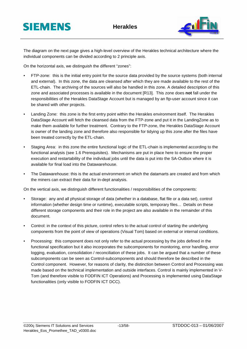
The diagram on the next page gives a high-level overview of the Herakles technical architecture where the individual components can be divided according to 2 principle axis.
On the horizontal axis, we distinguish the different “zones”:
• FTP-zone: this is the initial entry point for the source data provided by the source systems (both internal and external). In this zone, the data are cleansed after which they are made available to the rest of the ETL-chain. The archiving of the sources will also be handled in this zone. A detailed description of this zone and associated processes is available in the document [R13]. This zone does not fall under the responsibilities of the Herakles DataStage Account but is managed by an ftp-user account since it can be shared with other projects.
• Landing Zone: this zone is the first entry point within the Herakles environment itself. The Herakles DataStage Account will fetch the cleansed data from the FTP-zone and put it in the LandingZone as to make them available for further treatment. Contrary to the FTP-zone, the Herakles DataStage Account is owner of the landing zone and therefore also responsible for tidying up this zone after the files have been treated correctly by the ETL-chain.
• Staging Area: in this zone the entire functional logic of the ETL-chain is implemented according to the functional analysis (see 1.6 Prerequisites). Mechanisms are put in place here to ensure the proper execution and restartability of the individual jobs until the data is put into the SA-Outbox where it is available for final load into the Datawarehouse.
• The Datawarehouse: this is the actual environment on which the datamarts are created and from which the miners can extract their data for in-dept analysis.
On the vertical axis, we distinguish different functionalities / responsibilities of the components:
• Storage: any and all physical storage of data (whether in a database, flat file or a data set), control information (whether design time or runtime), executable scripts, temporary files... Details on these different storage components and their role in the project are also available in the remainder of this document.
• Control: in the context of this picture, control refers to the actual control of starting the underlying components from the point of view of operations (Visual Tom) based on external or internal conditions.
• Processing: this component does not only refer to the actual processing by the jobs defined in the functional specification but it also incorporates the subcomponents for monitoring, error handling, error logging, evaluation, consolidation / reconciliation of these jobs. It can be argued that a number of these subcomponents can be seen as Control-subcomponents and should therefore be described in the Control component. However, for reasons of clarity, the distinction between Control and Processing was made based on the technical implementation and outside interfaces. Control is mainly implemented in V-Tom (and therefore visible to FODFIN ICT Operations) and Processing is implemented using DataStage functionalities (only visible to FODFIN ICT DCC).

Herakles
©2009 Siemens IT Solutions and Services -14/58- STDDOC-013 – 01/06/2007 Herakles_Eos_Promethee_TAD_v0300.doc
Herakles Working Directory
HP Openview
Herakles Master Scheduler (Visual Tom Project)
Framework Repository
Herakles Scheduler
V-Tom Application
FtpZone Scheduler
V-Tom Application
Con
trol
P
roce
ssin
g S
tora
ge
DWH
FTP-Zone Landing Zone (LZ) Staging Area (SA) Datawarehouse (DWH)
EXTRC_SRC TRANSL TRANSF_SRC LOAD_SA LOAD_DWH
PRTRT_... INTAKE
MANAGE_ FTP
EXTRC_SPLIT
IDENT_...
MREF_...
MERGE_RECID
LOAD_PREP
LOAD_SA
LZ File System
LOAD_DWH
TRANS_DECTRT
CP_FTP_TO_LZ
EVAL CONSOL
EVAL CONSOL
EVAL CONSOL EVAL CONSOL
EVAL CONSOL
EVAL CONSOL
WATCHDOG
WATCHDOG WATCHD WATCHDOG CLEAN
Outbox
SYNC
WATCHD SYNC
WATCHD SYNC
(Sub-)component Zone Symbolic link

Herakles
©2009 Siemens IT Solutions and Services -15/58- STDDOC-013 – 01/06/2007 Herakles_Eos_Promethee_TAD_v0300.doc
The processing component is divided into the following subcomponents:
- MANAGE_FTP, described in [R13], and,
- INTAKE,
- EXTRC_<SRC> (one per source),
- TRANSL,
- TRANSF_<SRC> (one per source),
- LOAD_SA,
- LOAD_DWH,
- the subcomponents for monitoring, error handling, error logging, evaluation, consolidation / reconciliation, all described in the next chapter.
The job types (mapping types) described in the functional specifications (see [P03] and [P04] ) are grouped as follows:
- The “PRTRT_CLEAN” jobs will be implemented in the “MANAGE_FTP” subcomponent.
- The other “PRTRT_...” jobs (“PRTRT_SPLIT”, “PRTRT_LOAD”, “PRTRT_DELTA”, “PRTRT_PIVOT”, “PRTRT_UNION”), the “EXTRC_SPLIT “ jobs and the “TRANS_DECTRT” are grouped in the “EXTRC_<SRC>” subcomponents (one per source).
- The “IDENT_...” jobs (“IDENT_LOAD”, “IDENT_TKSEARCH”) and “MREF_...” jobs (“MREF_LOAD”, “MREF_TKSEARCH”, “MREF_TKSEARCH_CONTACT”) are grouped in the “TRANSL” subcomponent.
- The “MERGE_RECID” and “LOAD_PREP” jobs are grouped in “TRANSF_<SRC>” subcomponents (one per source),
- For performance reasons, the functionalities of the “LOAD” and “LOAD_CUR” jobs will be integrated and for recoverability / restartability reasons and to limit the data warehouse load as much as possible, the process will be executed in two phases:
� the “LOAD_SA” jobs (“LOAD_SA” subcomponent) executing all the logic and preparing data for the data warehouse in the staging area. These jobs will also integrate the logic implied by the “Late arriving records” change request that will be described in another document.
� the “LOAD_DWH” jobs (“LOAD_DWH” subcomponent) transferring the prepared data to the data warehouse. This subcomponent will also transfer the data prepared by the “TRANSL” subcomponent.

Herakles
©2009 Siemens IT Solutions and Services -16/58- STDDOC-013 – 01/06/2007 Herakles_Eos_Promethee_TAD_v0300.doc
The remainder of this document is divided into 2 main parts. The first part, chapter 3 Architectural components, is structured according to the subdivisions mentioned above. For reasons of clarity, it was agreed to treat the functionalities (vertical axis) in the following order: Storage – Control – Processing. Within each of these components the natural order of the zones are followed, from FTP to DWH.
In the second part, chapter 4 Architectural properties, we will clarify / proof how the proposed architecture meets the requirements of restarting, monitoring, error handling, logging and data integrity. In this chapter, frequent references will be made to the first part but no new concepts will be introduced. The approach for documenting the first part should assure that all components are covered.

Herakles
©2009 Siemens IT Solutions and Services -17/58- STDDOC-013 – 01/06/2007 Herakles_Eos_Promethee_TAD_v0300.doc
3. Architectural components The following diagram depicts the components of Herakles and their interfaces, which will be described in more detail in the following sections.
Control
Processing Storage
Scheduler (Visual TOM)
Sequence Starter (Unix script)
Monitoring (HP Openview)
FtpZone Manager (Unix script)
Sequences (DataStage)
Jobs (DataStage)
Watchdog
Monitoring, Technical error handling,
Reconciliation (measurement) (DataStage Sequence & Jobs)
Functional error handling / logging
(DataStage Container)
File System
DB2
FTP
LZ
SA
DWH
Framework
Repository
Cleaning LZ / SA (DataStage Sequence &
Jobs)
Evaluator / Consolidator (DataStage Jobs)
Synchronisation SA-DWH (Unix Scripts)
(3)
(Sub-)component Symbolic link
(16)
(11) (17)
(18)
(7)
(14)
(15)
(12)
(20)
(2)
(1) (4)
(5)
(6)
(8)
(9)
(10)
(21)
(19)
(13)

Herakles
©2009 Siemens IT Solutions and Services -18/58- STDDOC-013 – 01/06/2007 Herakles_Eos_Promethee_TAD_v0300.doc
1) V-Tom jobs executes control jobs in a cyclic mode
2) FTPZone Manager checks the FTP storage zone
3) FTPZone Manager scripts insert status records in the SAR_INCOMING table (see section 3.1.2.1 Framework Repository).
4) V-Tom launches the Sequence starter in a cyclic mode (see section 3.2.3 Herakles scheduler).
5) V-Tom sends messages to HP Openview (see section 3.2.3 Herakles scheduler).
6) The Sequence starter starts the level 1 DataStage Sequences (see section 3.2.4 Sequence starter and monitoring).
7) Subsequences are initiated and started
8) Sequences and subsequences call the Watchdog and retrieve the status of subsequences or jobs (see section 3.3.2.2 Error handling and execution tracing).
9) The Watchdog fills the Framework Repository runtime information (status, time,...) (see section 3.3.2.2 Error handling and execution tracing).
10) Sequences call the Evaluator and Consolidator components and process the returned information (see section 3.3.2 Processing framework).
11) The Evaluator, Consolidator, Synchronization components consult and update the Framework Repository (see section 3.3.2 Processing framework).
12) The Synchronization components move or copy datasets from SA working directory to the SA Outbox
13) DataStage job execution.
14) Copy files from FtpZone (see section 3.3.3 Landing zone).
15) Copy files to LZ (see section 3.3.3 Landing zone).
16) Jobs use / create datasets in the Staging area (see section 3.3.4 Staging Area).
17) DataStage LOAD DWH jobs update the data warehouse (see section 3.3.5.1 LOAD_DWH).
18) Jobs use container for functional error handling (3.3.2.2 Error handling and execution tracing).
19) DataStage functional error handler container logs functional errors in the Framework Repository (see section 3.3.2.2 Error handling and execution tracing).
20) Cleaning LZ/SA (see section 3.3.2.8 Cleaning).
21) Queries the framework repository to determine elements to be cleaned (see section 3.3.2.8 Cleaning).

Herakles
©2009 Siemens IT Solutions and Services -19/58- STDDOC-013 – 01/06/2007 Herakles_Eos_Promethee_TAD_v0300.doc
3.1. Storage
3.1.1. General overview
In general, the storage functionality consists of 2 different types of storage, namely databases and file systems, which are used to store different kinds of information in the different zones. This section will list and briefly describe the structure and function of the individual storage components of both types. We will however not describe the underlying storage-structures of the databases themselves (data files, san-volumes) since these are considered to be an integral part of the database and from a Herakles point of view to be a single component. Recommendations for optimizing this part can be found in the document [R10].
This way, we first identify the file systems:
• Ftp Zone file system: file system where the arriving data is stored. Also the intermediate files used in the cleansing process and finally the cleansed data can be found here. For the exact structure of this file system please refer to [R13].
• Landing Zone file system: when the data are made available to Herakles they will be copied from the ftp-zone into the Landing zone. This Landing Zone is a file system that, contrary to the Ftp Zone, is owned by the Herakles DataStage Account and is a specific file system with a large enough volume to hold the incoming flat files. Apart from these files, no other data will be held here. This file system is cleaned up when the data has been successfully loaded into the Datawarehouse.
• Herakles Working Directory: this is the directory that on one hand provides storage for all datasets in the ETL-process and on the other hand stores the executables (shell scripts), database definitions (sql-files), a temporary directory, a location for the log files, and so on. This directory is explicitly not called the Staging Area File System since it does not merely contain structures related to the staging area (the executables, logging, etc are also applicable to the Landing Zone and the Datawarehouse). This directory will be very light-weight since it only contains references to the actual data files, either stored in the Landing Zone and referenced by a UNIX symbolic link (i.e. a special kind of file that points to another file, much like a shortcut in Windows. A symbolic link does not contain the data in the target file. It simply points to another entry somewhere in the file system), or .ds-files containing references to the scratch and resource directories defined in the DataStage project). These resource and scratch directories are the ones containing the real data. For every node used, a different file system can be foreseen but for one node these 2 directories should reside on the same file system for performance reasons. A single file system (sufficiently large) is foreseen to hold these directories.
• Staging Area Outbox: this storage component holds the input for the final stage of the ETL-chain, namely the LOAD_DWH component and is generated by different job types depending on the type of table:
o Dimension and bridge tables: the new state to be inserted into the DWH is generated by the LOAD_SA-jobs.
o Reference tables: here, the new state is generated by the MREF-jobs belonging to that reference.

Herakles
©2009 Siemens IT Solutions and Services -20/58- STDDOC-013 – 01/06/2007 Herakles_Eos_Promethee_TAD_v0300.doc
o Fact tables (not applicable to Eos): for these tables, there does not exist any interdependency between the records within the same table. The data is generated by either a MERGE or a LOAD_PREP job type but no prioritization or update of other records is to be applied.
o Identification tables: Here, it is the IDENT-jobs that are responsible for generating the last state.
To maximize the performance of the final load into the DWH as well as as the performance of the jobs generating these data without forgetting the restarting/recovering capabilities, the choice has been made to use datasets to store these data.
Apart from these file systems; a number of database storage components can be identified. We can distinguish the following components:
• Framework repository: the framework repository is the component that contains a number of tables facilitating the execution of the individual sequences and jobs. The repository consists of two parts namely the “Design-time” and the “Run-time” tables, aptly named SAD (Staging area Design-time) and SAR (Staging area Run-time) tables. The design-time tables (SAD’s) serve to define all the functional components (jobs, signatures, sources and source-files) and their dependencies and can be viewed as a complete listing of the integrated functional code-base (all transformations defined by the functional analysis for the sources retained in an iteration). The run-time tables (SAR’s) serve to trace the execution of these functional components, allowing for a dynamic execution based upon available data (e.g. the SAR’s trace the number of records in and the validity of the datasets which allows the Sequences (see 3.3 Processing) to evaluate which jobs to run. Both the SAD and the SAR tables will be discussed in more detail in the following sections. In the following sections, contrary to the order of this section, this framework repository is discussed first because it is referred to when discussing the other components. The structure of the repository has already been elaborated in detail in the present document, but could be refined in the final global technical specification.
• The Datawarehouse (DWH): this is the actual environment on which the datamarts are created and from which the miners can extract their data for in-dept analysis. The logical model is already defined in the functional analysis and will not be altered at that level. This logical model is persisted in a straightforward manner following RDC (for storage) and SupDev (for naming) standards. However, a number of modifications (add-ons) are made at a technical level.
o Adding Fields to all tables to hold the LOAD_ID and timestamp of the first insertion and last update of any record in the Datawarehouse to facilitate the LOAD_DWH step and improve the traceability of the data.
o Setting up the indexing strategy to facilitate loading, querying and maintaining the data warehouse.
o The possibility of defining a partitioning strategy to allow for highly optimized load’s is not applicable yet, since this would require a DPF installation at the database level.

Herakles
©2009 Siemens IT Solutions and Services -21/58- STDDOC-013 – 01/06/2007 Herakles_Eos_Promethee_TAD_v0300.doc
3.1.2. Databases
3.1.2.1. Framework Repository
3.1.2.1.1. Design time repository (SAD) tables
The functional analysis applies an extremely rigid naming approach towards definition of jobs, sources, source files, signatures, and signature instances. One could say that the ensemble of these definitions also defines the entire code-base (for the functional part) since for every component it is strictly defined what his input-, output- and auxiliary-signatures or signature instances are and which job implementation supports this transformation. There are some exceptions were the implementation of the jobs will differ from the functional analysis, like the merge of the load_cur and the load, but there is no impact on the naming approach.
In order to support the desired run-time flexibility and avoid the hard-coding of this functional structure, the sequences (see 3.3 Processing) will need to have access to this (design-time) information. This information is stored in the SAD-tables which are structured as depicted in the following figure.
SAD_BRON
T_I_BRON_NOM
T_I_EIGNR
T_I_DESCR_NL
T_I_DESCR_FR
T_I_DESCR_DE
C_TIJD_LOAD_TK
SAD_BRON_TABLE
T_I_TABLE_NOM
T_BRON_BRON_NOM
T_I_TABLE_TYPE
N_I_MAX_STAP
SAD_SIGNATURE_INSTANCE
T_I_SIGNAT_INST_NOM
T_BRON_BRON_NOM
T_BRONTABLE_TABLE_NOM
T_SIGNAT_SIGNAT_NOM
SAD_UTILISATION
T_I_UTILS
T_SIGNATINST_SIGNAT_INST_NOM
T_BRON_BRON_NOM
T_BRONTABLE_TABLE_NOMT_JOB_JOB_NOM
T_SIGNAT_SIGNAT_NOM
T_I_STAP
SAD_ERROR_DESCRIPTION
C_I_ERR_CODE
T_I_ERR_TYPE
T_I_ERR_DESCR_EN
T_I_ERR_DESCR_NL
T_I_ERR_DESCR_FR
T_I_ERR_DESCR_DE
SAD_PRIORITEIT_A0301
T_BRON_BRON_NOM
N_I_PRIOR_VORM_JUR_TKT2
N_I_PRIOR_SIT_JUR_TKT2
N_I_PRIOR_ENTRP_CESS_RAIS_TKT2N_I_PRIOR_STATU_TKT2
N_I_PRIOR_MUNT_TKT2
N_I_PRIOR_REGIM_TVA_TKT2
N_I_PRIOR_FORF_TVA_TKT2
N_I_PRIOR_CCZE_TKT2
N_I_PRIOR_PERS_MORAL_TYPE_TKT2
N_I_PRIOR_DATE_INSCR_KBO_TK
N_I_PRIOR_DATE_AANV_TK
N_I_PRIOR_DATE_CESS_TK
N_I_PRIOR_DATE_CLOT_TK
N_I_PRIOR_DATE_TVA_HOEDA_TK
N_I_PRIOR_DATE_REGIM_TVA_TK
N_I_PRIOR_BOEK_AN_EXC_DEBUT_TK
N_I_PRIOR_BOEK_AN_EXC_FIN_TK
N_I_PRIOR_TVA_HOEDA
N_I_PRIOR_TVA_MENSL_REMBS
N_I_PRIOR_TVA_BEZW_REMBS
N_I_PRIOR_LIJST678
N_I_PRIOR_DROIT_TRCT_CEE
N_I_PRIOR_CAPIT
N_I_PRIOR_DUREE
N_I_PRIOR_BOEKH_ANNEE_FIN_JOUR
N_I_PRIOR_BOEKH_ANNEE_FIN_MOIS
N_I_PRIOR_JAARL_ASS_MOIS
N_I_PRIOR_NUM_BANK_KBO
N_I_PRIOR_IBAN_NUM
SAD_PRIORITEIT_A0201
T_BRON_BRON_NOM
N_I_PRIOR_AMBTR_EURO_TKT2
N_I_PRIOR_BIJK_ACTIV_TKT2
N_I_PRIOR_TAAL_TKT2
N_I_PRIOR_RAD_TKT2
N_I_PRIOR_REF_NUM
N_I_PRIOR_EEUW_NAISS
SAD_PRIORITEIT_A0117
T_BRON_BRON_NOM
N_I_PRIOR_PERS_PERS_TK
N_I_PRIOR_ENTRP_CESS_RAIS_TKT2
N_I_PRIOR_STATU_TKT2
N_I_PRIOR_DATE_INSCR_KBO_TK
N_I_PRIOR_DATE_AANV_TK
N_I_PRIOR_DATE_CESS_TK
N_I_PRIOR_DATE_CLOT_TK
SAD_PRIORITEIT_A0202
T_BRON_BRON_NOM
N_I_PRIOR_PERS_TK
N_I_PRIOR_REGIM_TVA_TKT2
N_I_PRIOR_SIT_JUR_TKT2
N_I_PRIOR_ENTRP_CESS_RAIS_TKT2
N_I_PRIOR_STATU_TKT2
N_I_PRIOR_FORF_TVA_TKT2
N_I_PRIOR_DATE_INSCR_KBO_TK
N_I_PRIOR_DATE_AANV_TK
N_I_PRIOR_DATE_CESS_TK
N_I_PRIOR_DATE_CLOT_TK
N_I_PRIOR_DATE_TVA_HOEDA_TK
N_I_PRIOR_DATE_REGIM_TVA_TK
N_I_PRIOR_TVA_HOEDA
N_I_PRIOR_TVA_MENSL_REMBS
N_I_PRIOR_TVA_BEZW_REMBS
N_I_PRIOR_LIJST678
N_I_PRIOR_DROIT_TRCT_CEE
N_I_PRIOR_DUREE
N_I_PRIOR_DENOM_SOCN_I_PRIOR_AFKOR
N_I_PRIOR_DENOM_HANDL
SAD_SEQUENCE
T_I_SEQ_NOM
T_I_CONFIG_FILE
SAD_PRIORITEIT_A0310
T_BRON_BRON_NOM
N_I_PRIOR_BOEKH_ANNEE_DEBUT_TK
N_I_PRIOR_BOEKH_ANNEE_FIN_TK
N_I_PRIOR_DATE_JAARL_ASS_TK
N_I_PRIOR_ACPT_CPT_DEPOT_TKN_I_PRIOR_DATE_BILAN
N_I_PRIOR_TAAL_TKT2
N_I_PRIOR_CPT_DEPOS_AARD_TKT2
SAD_PRIORITEIT_A0311
T_BRON_BRON_NOM
N_I_PRIOR_TAAL_TKT2
N_I_PRIOR_DENOM_SOC
N_I_PRIOR_AFKOR
N_I_PRIOR_DENOM_HANDL
SAD_OVERLAPPING
T_I_DOEL
T_I_INST
L_I_CHEV
SAD_REF_PREFIXE
T_I_DOEL
T_I_INST
T_I_PREFIX
SAD_REF_NOM_CHAMP
T_I_DOEL
T_I_NOM_CHAMP_CODE_NATUR
T_I_NOM_CHAMP_CODE_TECH
SAC_CONVERSION_COMMUNE
C_I_COM_CODE_ANC
C_I_COM_CODE_NIEUW
SAD_PRIORITEIT_A0110
T_BRON_BRON_NOM
N_I_PRIOR_TOELA_PHASE_TKT2
N_I_PRIOR_TOELA_RAIS_FIN_TKT2
N_I_PRIOR_DUREE
SAD_JOB_IMPLEMENTATION
T_I_JOB_IMPL_NOM
T_I_STAP
SAC_CONVERSION_BUREAU
C_I_BUR_CODE_ANC
C_I_BUR_CODE_NIEUW
SAD_JOB
T_I_JOB_NOM
T_JOBIMPL_JOB_IMPL_NOM
T_SEQ_SEQ_1_NOM
T_SEQ_SEQ_2_NOM
T_SEQ_SEQ_3_NOM
T_SEQ_SEQ_4_NOM
T_I_STAP
SAD_SIGNATURE
T_I_SIGNAT_NOM
SAD_REF_BRON_TABLE_VENTILATION
T_I_CAT
T_BRON_BRON_NOM
T_BRONTABLE_TABLE_NOM
T_I_JOB_NOM
T_I_SIGNAT_INST_NOM
T_I_SIGNAT_NOM

Herakles
©2009 Siemens IT Solutions and Services -22/58- STDDOC-013 – 01/06/2007 Herakles_Eos_Promethee_TAD_v0300.doc
Most of the concepts used in this schema are those that come directly from the functional analysis and will be discussed briefly here:
• SAD_BRON: contains the defined sources (with the version included in its name), description and owner. Other decorative fields can be added when necessary.
• SAD_BRON_TABLE: the tables that belong to a certain source. These are not actual files merely the logical table names of files that are to be expected.
• SAD_SIGNATURE: collection of all the signatures (i.e. the definition of the characteristics (fields, data types) of a table or file, on a functional level, independently from the effective persistence of the data) defined in the functional analysis.
• SAD_SIGNATURE_INSTANCE: the different instances of signatures linked to the source (group of source files) and specific source file that generates them.
• SAD_JOB: collection of all the functional jobs (mappings) defined in the functional analysis, and of some technical jobs for initialization purpose.
• SAD_JOB_IMPLEMENTATION: contains the actual DataStage job name that implements a certain functional job. There will be a difference between the functional job and its implementation in the case of a generic implementation of several functional jobs.
• SAD_ UTILISATION: contains the roles (Input, Output, Auxiliary, Reject) of the signature instances with respect to the jobs.
• SAD_SEQUENCE: contains the name of all sequences and permits specifying for level 1 sequences the Data Stage configuration file that will be used.
• SAD_ERROR_DESCRIPTION: contains the codes and messages related to the errors and warnings trapped in the ETL-process.
Moreover, some tables were added to parameterize some processes
• SAD_OVERLAPPING: specifies, according to the source and target of bridge tables, if time overlapping is allowed between records of the table. This information will be used by the “LOAD_SA” jobs.
• SAD_PRIORITEIT_*: specifies, per field of a specific target, the sources feeding this field and the related priority. . This information will also be used by the “LOAD_SA” jobs.
• SAD_REF_NOM_CHAMP: allows a generic implementation of “LOAD_DWH” jobs of generic referential tables, by specifying the name of the specific fields of these tables.
• SAD_REF_PREFIXE: allows to treat on a generic way referential tables fed by several source tables. This treatment is localised in the “MREF_*” jobs.
• SAD_REF_BRON_TABLE_VENTILATION allows to treat on a generic way several referential tables fed by only one source table.
At least, a special table has been added to support conversion
• SAC_CONVERSION_COMMUNE, conversion of old NIS – INS city codes
• SAC_CONVERSION_BUREAU, conversion of old customs office codes to the new codes.

Herakles
©2009 Siemens IT Solutions and Services -23/58- STDDOC-013 – 01/06/2007 Herakles_Eos_Promethee_TAD_v0300.doc
3.1.2.1.2. Run time repository (SAR) tables
Contrary to the design-time information in the SAD-tables, which is defined at roll-out and does not change during execution, there is also a lot of information that is generated at run-time (e.g. which sources arrived, which files, record counts, jobs executed, files generated by them, error trapping,…) and will also be used by the sequences to determine which jobs to run or which files to process. These tables form the basis for the communication between sequences and the synchronisation of these sequences. It is also here that the concept of the load-id (i.e. a unique number attribute to the delivery of a source) is first introduced (see 3.3.3 Landing zone).
The most important tables in this SAR-schema are:
• SAR_INCOMING: implements the interface with the Ftp-zone. The ftp-zone manager will insert in this table a record per available file (see also [R13]).
• SAR_LOAD: holds all the sources that were transferred from the landing zone to the staging area and their status at source level (i.e. “Ready for Extraction”, “Ready for Translation”, …, “Ready for Load DWH”). This table can be seen as an aggregate of what is in the SAR_LOAD_TABLE table. It is at this level that the LOAD_ID is a key field, resulting in the fact that any LOAD_ID applies only to one source delivered on one moment.
• SAR_LOAD_TABLE: the table SAR_LOAD is used to define the list of data sources. The table SAR_LOAD_TABLE is used to define per data source the list of files and their status. There is a relation 1:n between the table SAR_LOAD and SAR_LOAD_TABLE because one entry in the table SAR_LOAD has one or more entries in the table SAR_LOAD_TABLE.
• SAR_FILE: contains all the signature-instances that were actually generated for a certain LOAD_ID. It contains also record counts of the files in order to facilitate validation of a run. If jobs are restarted, the entries in this table are not overwritten but new records are inserted.
• SAR_SYNCHRONISATIE: supports the synchronisation between the staging area outbox and the data warehouse. The goal of this synchronisation is to avoid that data of the staging area outbox are modified while other SA processes are using it of while the data warehouse is loading.
These tables are referred to as the decisional tables since they are used by the sequences to evaluate if they actually have something available for treatment. This evaluation bases itself primarily on a field of the tables SAR_LOAD and SAR_LOAD_TABLE, indicating how far the processing of a source or a source table respectively, has advanced through the ETL-chain (i.e. “Ready for Extraction”, “Ready for Translation”, …, “Ready for Load DWH”).

Herakles
©2009 Siemens IT Solutions and Services -24/58- STDDOC-013 – 01/06/2007 Herakles_Eos_Promethee_TAD_v0300.doc
Apart from these tables, two more tables exist, serving more for a monitoring purpose:
• The SAR_RUN contains the log information of the job start time, stop time, duration and the status (success, warning, error) with which they finished.
• The SAR_ERROR_LOG contains the log information of the logical errors and warnings that are trapped within the jobs themselves (key not filled in, date converted to default, …).
SAD_BRON
T_I_BRON_NOM
T_I_EIGNR
T_I_DESCR_NL
T_I_DESCR_FR
T_I_DESCR_DE
C_TIJ D_LOAD_TK
SAD_BRON_TABLE
T_I_TABLE_NOM
T_BRON_BRON_NOM
T_I_TABLE_TYPE
N_I_M AX_STAP
SAR_RUN
C_I_RUN_TK
T_J OBIMPL_J OB_IM PL_NOM
C_LOAD_LOAD_TK
T_I_DOEL
T_I_INST
N_I_J OB_STATU
S_I_DEBUT
S_I_FIN
N_I_DUREE
SAR_LOAD
C_I_LOAD_TK
T_BRON_BRON_NOM
S_I_EXTRC
S_I_ARRIV
S_I_TRANS
S_I_LOAD
N_I_STAP
T_I_STATU
SAR_LOAD_TABLE
C_LOAD_LOAD_TK
T_BRON_BRON_NOM
T_BRONTABLE_TABLE_NOM
N_I_STAP
T_I_STATU
SAR_INCOM ING
T_I_FILE_NOM
T_BRON_BRON_NOM
T_BRONTABLE_TABLE_NOM
S_I_EXTRC
S_I_ARRIV
S_I_TRANS
N_I_REC_NBR
T_I_STATU
SAR_ERROR_LOG
C_ERRDESCR_ERR_CODE
T_J OBIM PL_J OB_IM PL_NOM
C_LOAD_LOAD_TK
T_I_DOEL
T_I_INST
S_I_ERROR
C_I_REC
T_I_DATA
SAR_FILE
T_I_FILE_NOM
C_LOAD_LOAD_TK
C_RUN_RUN_TK
T_SIGNATINST_SIGNAT_INST_NOM
T_BRON_BRON_NOM
T_BRONTABLE_TABLE_NOM
S_I_INS
N_I_REC_NBR
SAD_UTILISATION
T_I_UTILS
T_SIGNATINST_SIGNAT_INST_NOM
T_BRON_BRON_NOM
T_BRONTABLE_TABLE_NOM
T_J OB_J OB_NOM
T_SIGNAT_SIGNAT_NOM
T_I_STAP
SAD_JOB_IMPLEM ENTATION
T_I_J OB_IM PL_NOM
T_I_STAP
SAR_SYNCHRONISATIE
T_SIGNAT_SIGNAT_NOM
T_I_STAP
L_I_SA_LEZEN_CLOT
L_I_DWH_OVERS_CLOT
L_I_SA_OVERS_CLOT
SAD_ERROR_DESCRIPTION
C_I_ERR_CODE
T_I_ERR_TYPE
T_I_ERR_DESCR_EN
T_I_ERR_DESCR_NL
T_I_ERR_DESCR_FR
T_I_ERR_DESCR_DE
SAD_PRIORITEIT_A0201
T_BRON_BRON_NOM
N_I_PRIOR_AMBTR_EURO_TKT2
N_I_PRIOR_BIJK_ACTIV_TKT2
N_I_PRIOR_TAAL_TKT2
N_I_PRIOR_RAD_TKT2
N_I_PRIOR_REF_NUM
N_I_PRIOR_EEUW_NAISS
SAD_PRIORITEIT_A0117
T_BRON_BRON_NOM
N_I_PRIOR_PERS_PERS_TK
N_I_PRIOR_ENTRP_CESS_RAIS_TKT2
N_I_PRIOR_STATU_TKT2
N_I_PRIOR_DATE_INSCR_KBO_TK
N_I_PRIOR_DATE_AANV_TK
N_I_PRIOR_DATE_CESS_TK
N_I_PRIOR_DATE_CLOT_TK
SAD_PRIORITEIT_A0202
T_BRON_BRON_NOM
N_I_PRIOR_PERS_TK
N_I_PRIOR_REGIM _TVA_TKT2
N_I_PRIOR_SIT_J UR_TKT2
N_I_PRIOR_ENTRP_CESS_RAIS_TKT2
N_I_PRIOR_STATU_TKT2
N_I_PRIOR_FORF_TVA_TKT2
N_I_PRIOR_DATE_INSCR_KBO_TK
N_I_PRIOR_DATE_AANV_TK
N_I_PRIOR_DATE_CESS_TK
N_I_PRIOR_DATE_CLOT_TK
N_I_PRIOR_DATE_TVA_HOEDA_TK
N_I_PRIOR_DATE_REGIM _TVA_TK
N_I_PRIOR_TVA_HOEDA
N_I_PRIOR_TVA_M ENSL_REM BS
N_I_PRIOR_TVA_BEZW_REM BS
N_I_PRIOR_LIJ ST678
N_I_PRIOR_DROIT_TRCT_CEE
N_I_PRIOR_DUREE
N_I_PRIOR_DENOM _SOC
N_I_PRIOR_AFKOR
N_I_PRIOR_DENOM _HANDL
SAD_SEQUENCE
T_I_SEQ_NOM
T_I_CONFIG_FILE
SAD_PRIORITEIT_A0310
T_BRON_BRON_NOM
N_I_PRIOR_BOEKH_ANNEE_DEBUT_TK
N_I_PRIOR_BOEKH_ANNEE_FIN_TK
N_I_PRIOR_DATE_J AARL_ASS_TK
N_I_PRIOR_ACPT_CPT_DEPOT_TK
N_I_PRIOR_DATE_BILAN
N_I_PRIOR_TAAL_TKT2
N_I_PRIOR_CPT_DEPOS_AARD_TKT2
SAD_PRIORITEIT_A0311
T_BRON_BRON_NOM
N_I_PRIOR_TAAL_TKT2
N_I_PRIOR_DENOM _SOC
N_I_PRIOR_AFKOR
N_I_PRIOR_DENOM _HANDL
SAD_OVERLAPPING
T_I_DOEL
T_I_INST
L_I_CHEV
SAD_REF_PREFIXE
T_I_DOEL
T_I_INST
T_I_PREFIX
SAD_REF_NOM _CHAM P
T_I_DOEL
T_I_NOM_CHAM P_CODE_NATUR
T_I_NOM_CHAM P_CODE_TECH
SAD_PRIORITEIT_A0110
T_BRON_BRON_NOM
N_I_PRIOR_TOELA_PHASE_TKT2
N_I_PRIOR_TOELA_RAIS_FIN_TKT2
N_I_PRIOR_DUREE
SAD_SIGNATURE_INSTANCE
T_I_SIGNAT_INST_NOM
T_BRON_BRON_NOM
T_BRONTABLE_TABLE_NOM
T_SIGNAT_SIGNAT_NOM
SAD_SIGNATURE
T_I_SIGNAT_NOM
SAD_JOB
T_I_J OB_NOM
T_J OBIM PL_J OB_IM PL_NOM
T_SEQ_SEQ_1_NOM
T_SEQ_SEQ_2_NOM
T_SEQ_SEQ_3_NOM
T_SEQ_SEQ_4_NOM
T_I_STAP
SAD_REF_BRON_TABLE_VENTILATION
T_I_CAT
T_BRON_BRON_NOM
T_BRONTABLE_TABLE_NOM
T_I_J OB_NOM
T_I_SIGNAT_INST_NOM
T_I_SIGNAT_NOM
SAC_CONVERSION_COM M UNE
C_I_COM_CODE_ANC
C_I_COM_CODE_NIEUW
SAD_PRIORITEIT_A0301
T_BRON_BRON_NOM
N_I_PRIOR_VORM _J UR_TKT2
N_I_PRIOR_SIT_J UR_TKT2
N_I_PRIOR_ENTRP_CESS_RAIS_TKT2
N_I_PRIOR_STATU_TKT2
N_I_PRIOR_M UNT_TKT2
N_I_PRIOR_REGIM _TVA_TKT2
N_I_PRIOR_FORF_TVA_TKT2
N_I_PRIOR_CCZE_TKT2
N_I_PRIOR_PERS_M ORAL_TYPE_TKT2
N_I_PRIOR_DATE_INSCR_KBO_TK
N_I_PRIOR_DATE_AANV_TK
N_I_PRIOR_DATE_CESS_TK
N_I_PRIOR_DATE_CLOT_TK
N_I_PRIOR_DATE_TVA_HOEDA_TK
N_I_PRIOR_DATE_REGIM _TVA_TK
N_I_PRIOR_BOEK_AN_EXC_DEBUT_TK
N_I_PRIOR_BOEK_AN_EXC_FIN_TK
N_I_PRIOR_TVA_HOEDA
N_I_PRIOR_TVA_M ENSL_REM BS
N_I_PRIOR_TVA_BEZW_REM BS
N_I_PRIOR_LIJ ST678
N_I_PRIOR_DROIT_TRCT_CEE
N_I_PRIOR_CAPIT
N_I_PRIOR_DUREE
N_I_PRIOR_BOEKH_ANNEE_FIN_J OUR
N_I_PRIOR_BOEKH_ANNEE_FIN_M OIS
N_I_PRIOR_J AARL_ASS_M OIS
N_I_PRIOR_NUM _BANK_KBO
N_I_PRIOR_IBAN_NUM
SAC_CONVERSION_BUREAU
C_I_BUR_CODE_ANC
C_I_BUR_CODE_NIEUW

Herakles
©2009 Siemens IT Solutions and Services -25/58- STDDOC-013 – 01/06/2007 Herakles_Eos_Promethee_TAD_v0300.doc
3.1.2.2. Datawarehouse
3.1.2.2.1. Adding technical fields
To facilitate maintenance by augmenting the traceability of the data on one hand and to be able to minimize load-volumes on the other a number of technical fields were added to the Datawarehouse storage. The following fields were uniformly added to all tables:
• C_LOAD_LOAD_INS_TK (Bigint): contains the value of the load-id that initially created the record. This is actually not a new field but is the rename of the original C_I_LOAD_TK that was already present in most (but not all) tables.
• C_LOAD_LOAD_UPD_TK (Bigint): contains the value of the load-id that last updated the record.
• S_I_INS (Timestamp): date and time of the initial creation of the record.
• S_I_UPD (Timestamp): date and time of the last update of the record.
• S_I_DB_UPD (Timestamp): date and time of the last insertion / update of the record in the database.
It can be argued that the UPD-fields have no meaning for tables were by definition no updates will be done (contacts, white Identification…). For reasons of code-base uniformity and ease of development, these fields will be added anyway.
3.1.2.2.2. Primary keys
To guarantee in-table data integrity, a primary key is defined on every table. More in detail, we again have to distinguish between the different types of tables we have:
• Dimension-tables: for the dimension tables (T1, T2 and actual tables) The primary keys follow directly from the functional analysis (_TK for T1 and actual, _TKT2 for T2-tables)
• Bridge tables: these tables have interdependency between the records and in some cases a date chaining. The primary key can be derived from the functional analysis on a table by table basis. The exact definition of the key per table will be available in the Global Technical Specification.
• Reference tables: since, according to the functional analysis, the reference tables are a special (simplified) case of the dimensions the same reasoning applies here resulting in a primary key on the TKT2-field.
• Identification tables: here, the primary keys can also be derived from the analysis and will also be available in the global specification.
• Fact tables (not in release 1): where the previous keys can be seen as functional keys (real business meaning) the primary key of a fact table is a strictly technical one.
3.1.2.2.3. Referential integrity
It is common practice in datawarehouses not to implement foreign key constrains (see among others [R10]). The referential integrity of the database is managed at the application level (in this case the ETL-process). However, one may not have too much confidence in an implementation. Therefore, an integrity validation process could be foreseen that checks the data integrity between the tables. This process (implemented in db2-stored procedures) could be run at regular intervals when the data warehouse usage is low (e.g. once a week during the weekend). The integration of such a procedure is out of implementation scope.

Herakles
©2009 Siemens IT Solutions and Services -26/58- STDDOC-013 – 01/06/2007 Herakles_Eos_Promethee_TAD_v0300.doc
Referential integrity is not the only reason why one would want to implement foreign key constraints. Another reason would be to support the query optimizer to increase performance. For this, DB2 offers the concept of “informational constraints”. These “constrains” are not continuously checked so no overhead is added during loading but they do serve provide the necessary information for the query optimizer. All foreign references present in any table in the Datawarehouse will have such an informational constraint defined.
3.1.2.2.4. Indexing strategy
Apart from the indexes that where automatically created to support the primary keys, indexes can be created to support the following. In this document, we only describe which indexes could serve which goal without actually defining them in detail. This will be described in the technical specification. Also the mechanism for maintaining them will be chosen on a case by case basis and described in that document.
• Optimizing query performance: for this, indexes can be defined on the foreign key fields of dimension, bridge and fact tables. These indexes will be defined in function of actual usage statistics (black box) or based on the definition of the data marts that are to be rolled out.
• Optimizing load performance: for the fact tables, no additional indexes are required since no fact insertion will give rise to an update (no record interdependency). For the dimensions, bridges and reference tables, where updates are possible, the primary key index will suffice so no additional indexes are needed for the load.
• Supporting maintenance: for manual interventions, indexes on the 4 technical fields are foreseen on all tables. Apart from that, to support the referential integrity validation process, additional indexes can be foreseen for the high-cardinality-links.

Herakles
©2009 Siemens IT Solutions and Services -27/58- STDDOC-013 – 01/06/2007 Herakles_Eos_Promethee_TAD_v0300.doc
3.1.3. File Systems
3.1.3.1. Ftp zone
As stated above, a description of the directory structure of the Ftp-zone can be found in the document [R13].
3.1.3.2. Landing Zone
The landing zone itself does not have an elaborated directory structure. In fact, the Intake component (see 3.3.3 Landing zone) will place the incoming files in a directory named LandingZone/YYYYMMDDHHMM/ where YYYYMMDDHHMM contains the extraction date and time as it was inserted in the SAR_INCOMING table.
Cleaning this LZ is done together with the cleaning of the Staging area when a certain source was successfully treated and all intermittent datasets are being deleted (see 3.3.2.8 Cleaning). As already mentioned, it is not the responsibility of the LZ to construct and maintain an archive of all the data that was delivered. This source archiving is part of the Ftp zone since this zone is shared between multiple projects (see [R13]).
3.1.3.3. Staging Area
3.1.3.3.1. Herakles Working Directory
The Herakles Working Directory contains the main subdirectories described in the following sections. More technical subdirectories will be described in detail in the global technical specification.
3.1.3.3.2. Signatures Directory
The signatures directory holds a subdirectory for every signature defined in the functional analysis (and listed in the SAD_SIGNATURE table). Within this directory, all the signature instances (.ds files) for the different LOAD_ID’s are stored (the LOAD_ID is contained in the name of the file). This signature directory allows for all the files that belong to a certain signature to be located in the same place. This has multiple advantages ranging from ease of cleaning the datasets when a load has successfully finished to facilitating unit tests because one always knows where the files will be located. This mechanism, together with the symbolic linking described in the next section, also eliminates the need for moving files in between jobs.
3.1.3.3.3. Jobs directory
The jobs directory likewise holds a subdirectory for every functional job that has been defined in the analysis (mappings) with the name of the functional job for which it was created. These directories correspond with the entries in the SAD_JOB table. Every one of these subdirectories contains in its turn the following 4 subdirectories: in, out, aux, and rej in which symbolic links are stored towards the signature directories and which play the role of respectively input, output, auxiliary (like a lookup, or delta-current dataset) and reject depending on what has been defined in the SAD_UTILISATION table.
This way, any job will always go looking for his input data and putting his output data in the correct location without the necessity of moving the .ds files themselves.

Herakles
©2009 Siemens IT Solutions and Services -28/58- STDDOC-013 – 01/06/2007 Herakles_Eos_Promethee_TAD_v0300.doc
The picture below describes a typical case of this mechanism. The EXTRC_SPLIT job has as one of its outputs the signature NK_Y0211_CODE_ACTIVITE_PROFESSIONNELLE which serves also as input for the MREF_TKSEARCH_Y0211 job. Instead of moving the file from one OUT to the other IN, which would imply that we would have to foresee some scripting to support this and an some of control logic in the case of failure for resetting the system in its initial state, we create two UNIX symbolic link in both the OUT and the IN directories that point towards the signature directory where the actual data are stored. This mechanism combined with DataStage’s full restartability, where an output file is not overwritten but placed on stand-by until the job has correctly finished, adds a great deal to the restartability of the entire system.
The following screenshot gives an example of a directory structure that will be automatically generated a roll-out time on the basis of the SAD repository tables.
Signatures-directory
EXTRC_SPLIT_KBOBCE_FEKBO_070_570 MREF_TKSEARCH_Y0211
NK_Y0211_CODE_ACTIVITE_PROFESSIONNELLE NK_...
IN REJ AUX OUT IN REJ AUX OUT
Jobs-directory

Herakles
©2009 Siemens IT Solutions and Services -29/58- STDDOC-013 – 01/06/2007 Herakles_Eos_Promethee_TAD_v0300.doc
3.1.3.3.4. Staging Area Outbox
As already described in the introduction of this chapter, the SA Outbox can be divided in 4 “types” storage components each with his own specificities.
• The Dimension and Bridge tables: with this we mean the (rather large) tables where there exists a dependency between the records due to some prioritization or chaining mechanism. Examples of such tables are the A0201_PERSONNE_PHYSIQUE, A0301_PERSONNE_MORALE but also the A0108_ACTIVITEIT (bridge table) where the insertion of a record may also mean an update (closure) of a previous one.
• The Reference tables (Ynnnn, A0120, …): these are similar to the dimension tables in a sense that an insertion may also give rise to an update on that table but one difference with the dimensions can already be found in the volumes of the tables: where the dimensions are expected to have a number of records in the order of magnitude of 1E6 to 1E7, the reference tables will be limited to 1E3 or 1E4 and most of them will not even contain that much. Apart from that, these tables will need to be available to the ETL-process to facilitate the lookup of the technical keys of referential code values.
• The Identification tables (A0102, B0107): these are similar to the dimensions in a way that they will contain large volumes. On the other hand, they resemble the reference tables in that they require look-ups on the current state.
• The Fact tables (not in release 1): here, there is not interdependency between records so they can be inserted without any bother with respect to functional logic.
Based upon these and taking into account the performance and restart capabilities discussed above, as well as the results of the executed POC’s the datasets have been chosen as physical storage. Extreme care must be taken in the management of the “current state” (see 3.3.2.4 Stateful jobs). A mechanism with one memory position (i.e. a current and a new state are available with the possibility to revert to the previous version in case of execution-failure) is foreseen.

Herakles
©2009 Siemens IT Solutions and Services -30/58- STDDOC-013 – 01/06/2007 Herakles_Eos_Promethee_TAD_v0300.doc
3.2. Control
3.2.1. Herakles Master Scheduler
The scheduler utility Visual Tom is used to automate the ETL process. The main responsibility of the usage of this utility resides in the scheduling of the ETL process with an overall visual status reporting towards the Data warehouse administrator.
3.2.2. Ftp-zone scheduler
See document [R13].
3.2.3. Herakles scheduler
SEQ_1_TRANSL
SEQ_1_LOAD_SA
SEQ_1_LOAD_DWH
SEQ_1_EXTRC_HARCODED
SEQ_1_EXTRC_KBOBCE
SEQ_1_EXTRC_BTWTVA
SEQ_1_EXTRC_NPP
...
SEQ_1_INTAKE
SEQ_1_TRANSF_HARCODED
SEQ_1_TRANSF_KBOBCE
SEQ_1_TRANSF_BTWTVA
SEQ_1_TRANSF_NPP
...
Herakles scheduler
Cyclic launch LZ SA DWH

Herakles
©2009 Siemens IT Solutions and Services -31/58- STDDOC-013 – 01/06/2007 Herakles_Eos_Promethee_TAD_v0300.doc
As explained in the section 3.3 Processing, the sequences have been structured in several levels, each with its own responsibility. The sequences of level 1 will be exposed to the Herakles scheduler.
V-Tom launches the Sequence starter (see 3.2.4) for each individual level 1 sequence every X minutes (adaptable V-Tom Parameter, which can be specific for each sequence). In the case of a technical error (all logical errors are trapped in the DataStage jobs) raised by the level 1 sequence and returned by the Sequence starter, the execution loop is halted and will be in “EN ERREUR” modus till manual intervention.
The level 1 sequences are the following:
- 1 “SEQ_1_INTAKE” sequence, which fetches the available source-files from the Ftp-Zone,
- 1 “SEQ_1_EXTRC_<SRC>” extraction sequence for each data source,
- 1 “TRANSL” sequence, which translates the natural keys to technical data warehouse keys and also loads the Staging Area outbox with the referential and identification data.
- 1 “SEQ_1_TRANSF_<SRC>” transformation sequence for each data source,
- 1 “SEQ_1_LOAD_SA” sequence, which loads the Staging Area outbox,
- 1 “SEQ_1_LOAD_DWH” sequence, which loads the data warehouse, on the basis of the Staging Area outbox.
Although the sequences are executed every X minutes they will only start executing actual jobs when there is actual data available. This decision is taken by the Evaluator-component that is integrated in the level 1 and 2 sequences, and bases itself on the information available in the SAR-tables (SAR_BRON or SAR_BRON_TABLE depending on the sequence level).
For the specific case of the “SEQ_1_LOAD_DWH” sequence, the decision of whether or not to update the data warehouse is taken within the SEQ_1_LOAD_DWH at a global level (i.e. not for every source individually). There are 2 cases in which the load can be started:
- all sources that have been delivered are in a state ready for loading (advancement field in the SAR_BRON table).
- not all sources present in the SAR are in a state ready for loading but a certain “last acceptable time for loading” (also known as drop dead time and defined at system level) has been reached. In this case the load will start, treating those sources that are in the correct state. If no sources are available in the correct state, no load is done since no changes took place.
When we arrive in the second case and a load is done, the V-Tom component will stop executing the sequence and no more evaluations will be done. Sources that arrive later will be automatically loaded the next day.
All sequences can be run in parallel, but the implementation of the V-Tom processes is so defined that only 1 instance of a sequence can be executed at once. If needed, V-Tom will put a process in wait status and start the process again after the termination of the sequence. The actual time frame in which the V-Tom processes will be executed will be defined during the production setup.
According to recent developments of the V-Tom team, the interface to HP Openview is implemented at the V-Tom level and there is no more need of a specific implementation.

Herakles
©2009 Siemens IT Solutions and Services -32/58- STDDOC-013 – 01/06/2007 Herakles_Eos_Promethee_TAD_v0300.doc
3.2.4. Sequence starter and monitoring
The Sequence starter component, implemented as a Unix script is responsible for
- executing the level 1 DataStage sequences, on the basis of the parameters sent by V-Tom (DataStage project, sequence name, DB2 instance, DB2 schema).
- returning the status (success or error) raised by the sequence to V-Tom
As stated in the previous section, the HP Openview monitoring is implemented at the V-Tom level. The goal of this level of monitoring is to better control the FodFin distributed environment.
The operational monitoring is done via HP Openview and on a more detailed level within the SAR tables.
3.2.4.1. Detailed Operational en functional monitor ing
Via HP Openview, the sanity of the Herakles can be monitored and dependencies can be traced between application and infrastructural problems.
In addition to this monitoring, a more detailed logging mechanism has been made available to the DWH Administrator, through the SAR tables:
• The SAR_RUN monitors the job start time, stop time, duration and the status (success, warning, error) with which they finished.
• The SAR_ERROR_LOG monitors the logical errors and warnings that are trapped within the jobs themselves (key not filled in, date converted to default, …).

Herakles
©2009 Siemens IT Solutions and Services -33/58- STDDOC-013 – 01/06/2007 Herakles_Eos_Promethee_TAD_v0300.doc
3.3. Processing
3.3.1. General overview
In essence, the architecture that is described here attempts to describe a run-time environment that allows for the implementation of the logic described in the functional analysis. In this functional analysis, care has been taken in defining a uniform mechanism consisting of a number of job types that would be applicable to any source. This mechanism is described at a high level in the functional analysis (see 1.6 Prerequisites) and is further applied to the different sources during the individual iterations.
This architecture will describe a framework that allows for running this mechanism applied to a number of sources, where every source has the same files arriving at regular intervals, in a way as to achieve maximum performance and reusability, furthermore allowing for the prioritization of components to execute and full restart capabilities in case of individual or collective job failure.
To achieve this, first of all, the functional analysis has been studied in detail since it describes the structure of the framework that is to be implemented. However, the structure defined in the analysis is a logical / functional one which not necessarily means that a 1 to 1 translation of this structure towards a technical implementation is the optimal choice. After careful examination of the dependencies between the different job types, we technically grouped them into a number of execution steps which form coherent units of work. These steps will appear (tailored to a specific source) for every source that is to be implemented and are described in more detail in the section 3.3.2.1 Technical grouping of job types.
Apart from the structural aspects that find their origin in the functional analysis, the architectural framework also has an important responsibility in managing the actual execution of the functional jobs. Since for every source new data arrive on a regular basis, all these different loads for all these sources have to be distinguished, traced, and possibly prioritized. This can be seen as a functional tracing of the jobs executed where we monitor the files that where created, record counts, reconciliation information, and so on. On the other hand there is also a need for technical tracing of the jobs by which we mean, the verification (and logging) that a job finished OK or, if not, that the error is trapped, reported, propagated to the higher levels and steps are taken to ensure the job context is put in its initial state again so that it can be re-executed at a later time.
To fulfill these requirements with respect to execution and tracing, there are 2 main mechanisms put in place. For all that concerns tracing (functional and technical) and logging aspects, a component (WatchDog) was introduced which is implemented as a DataStage sequence and which follows every subsequence and functional job execution to trap the necessary errors, count the number of records on input and output, and insert into the SAR_RUN table. A full description of this WatchDog component and its responsibilities can be found in section 3.3.2.2 Error handling and execution tracing.
A second mechanism that was put in place to ensure the proper execution of the functional jobs for a given source and load is the definition of DataStage sequence levels, each with its own responsibility. This structuring of sequences does not change the functional dependencies defined in the functional specifications (see [P02]), but increase the manageability of the development, the readability and maintainability. The sequence levels will be briefly described here, discussed in detail in section 3.3.2 Processing framework and finally applied to the different steps in the section 3.3.3 Landing zone, 3.3.4 Staging Area, 3.3.5 Datawarehouse. For a detailed description of the jobs themselves, we refer to the technical specifications and to the POC implementations.

Herakles
©2009 Siemens IT Solutions and Services -34/58- STDDOC-013 – 01/06/2007 Herakles_Eos_Promethee_TAD_v0300.doc
• Sequence Level 1: SEQ_1_INTAKE and SEQ_1_<STEP>[_<SRC>] where <STEP> corresponds to the technical grouping of jobs (see 3.3.2.1) and _<SRC> corresponds to the source and is only added for level 1 extraction (EXTRC) and transformation (TRANSF) sequences (e.g. SEQ_1_EXTRC_KBOBCE and SEQ_1_TRANSF_KBOBCE, but SEQ_1_TRANSL). Extraction and transformation (and their associated subsequences and jobs) are called “source centric”, because they are specific for a given source. The other sequences (and their associated subsequences and jobs) are called “target centric”, because they focus on the target (i.e. one or more table of the data warehouse) and are not specific for a given source). SEQ_1_INTAKE is a special case and only consists in this level and is responsible for creating the load-id’s of new source files. In all other cases, this level is responsible for finding the load-id’s that are in a state “ready” for treatment for this step. For the extractions and transformation, this is source-specific, for the others, this is done “cross-source”.
• Sequence Level 2: the main responsibility of this level is to evaluate the actual files (some files may be optional) that are present and ready for treatment by this step. The main difference with level 1 sequences is that level 1 treats the load-id’s (actual source level, cf. SAD_BRON table) where the level 2 sequences treat the different files (level SAD_BRON_TABLE).
• Sequence level 3: this level does the actual execution of the functional jobs and all that this implies with respect to error handling, rejects, record counting, state-management. In some cases, the generic implementation of a job for several files of a source will be implemented at this level (e.g. PRTRT_LOAD_HARDCODED_*, MREF_*). In other cases, like the LOAD_SA, this third level can be used to make the sequences less complex and more manageable.
• Sequence level 4: for some functional jobs that have a generic implementation, a fourth sequence level is foreseen which controls the parameterization of such a generic job for the different functional jobs. The fourth level is added when the generic job follows other jobs (e.g. the PRTRT_PIVOT_CODE_GENERAL_* that follows the PRTRT_SPLIT_CODE_GENERAL). As for the third level, this level can also be used to make the sequences less complex and more manageable.

Herakles
©2009 Siemens IT Solutions and Services -35/58- STDDOC-013 – 01/06/2007 Herakles_Eos_Promethee_TAD_v0300.doc
3.3.2. Processing framework
3.3.2.1. Technical grouping of job types
As explained in the General Overview, the different functional job types (mapping types) are regrouped in a number of technical steps or “units of work” that will be implemented in DataStage sequences. On one hand this was done to diminish the visible granularity at the V-Tom level where there is no need to disclose underlying functionalities that are part of one logical unit. On the other hand, it permits to insert certain “validation” or “reconciliation” points in the chain (see sections 3.3.2.1.1, 3.3.2.1.2 and 3.3.2.2.1 for more details).
• EXTRC_<SRC>: the Extraction step, implemented for every source individually, groups the job types of the groups PRTRT, EXTRC, and TRANS_DECTRT.
• TRANSL: the Translation step (source independent) is responsible for the natural key to technical key translations. It groups the jobs types of the groups IDENT and MREF (both loads and tksearches). It also loads the Staging Area Outbox with referential and identification data.
• TRANSF_<SRC>: the transformation step, implemented for every source individually, to increase the extensibility (a new source will not have impact on a existing TRANSF sequence), groups the MERGE_RECID and the LOAD_PREP job types.
• LOAD_SA: this step loads the Staging Area Outbox and contains only the LOAD_SA jobs.
• LOAD_DWH: the actual loading into the Datawarehouse from the data prepared in the Staging Area Outbox. This step allows for the clear separation between the staging area and the data warehouse itself so that they become separately scalable. This clear separation increases the recoverability and minimize the load of the data warehouse
3.3.2.1.1. Sequence level 1: load-id creation or ev aluation
The level 1 INTAKE sequence is responsible for creating load-ids for new sources files, declared in the SAR_INCOMING table by the FtpZone manager. This table defines the interface between the Ftp zone and the landing zone. This sequence also defines, based on the SAR_INCOMING table, the symbolic links between the staging area signature directories and the landing zone.
As depicted beneath, the other level 1 sequences first execute a load-id evaluator (EVAL_LOAD), which will generate a list of load-ids that are ready for treatment. The bases for this evaluation are the Staging Area Run-time tables. More in particular, this EVAL_LOAD bases itself on the table SAR_LOAD (since it is load-id centric) to generate the list of load-id’s, which are subsequently used to execute the level 2 sequence one after the other.
SEQ_2_EXTRC_KBOBCE EVAL_LOAD
SEQ_1_EXTRC_KBOBCE
CONSOL_LOAD
loop dependency

Herakles
©2009 Siemens IT Solutions and Services -36/58- STDDOC-013 – 01/06/2007 Herakles_Eos_Promethee_TAD_v0300.doc
The consolidate component (CONSOL_LOAD) exists to update the SAR_LOAD table when the execution of the level sequence for a particular load-id succeeded. For this, it does not base itself on the output of the jobs but rather on the contents of the SAR_LOAD_TABLE where he verifies that all source-files have augmented their advancement field so that he may augment the advancement in the SAR_LOAD table (the advancement field in the SAR_LOAD_TABLE is managed one level lower in the level 2 sequences).
This consolidation is a form of reconciliation at source instance level.
In the case of target centric sequences, the EVAL_LOAD component can be replaced by the EVAL_TARGET component, which generate for all load ids the targets and instances for the sequence, and the CONSOL_LOAD component by the CONSOL_ALL component, which consolidates all processed load ids. When the level 1 sequence splits the processing in several independent level 2 sequences, the EVAL_TARGET component can also be placed in these level 2 sequences.
For sequences feeding the staging area outbox (TRANSL and LOAD_SA) and the LOAD_DWH sequence, the level 1 sequence will also contain a synchronisation component. This component, implemented as a Unix shell script bases itself on the SAR_SYNCHRONISATIE table. The goal of this synchronisation is to avoid that data of the staging area outbox are modified while other staging area processes use them or while the data warehouse is loading.
3.3.2.1.2. Sequence level 2: file evaluation
Any level 2 sequence has a load-id as parameter. The fact that the level 1 sequence passes it a load-id does not necessarily mean that all files for that source (belonging to the load-id) were actually delivered. The EVAL_LOAD_TABLE component also bases itself on the SAR tables, more in particular the SAR_LOAD_TABLE table.
There exists at this level a consolidate component (CONSOL_LOAD_TABLE), which bases itself on the SAR_FILE table (which was filled in by the Watchdog), checks that all necessary files are present in this table, which means they were correctly created and updates the advancement field of the SAR_LOAD_TABLE table (so that also the consolidator of the level 1 sequence may use it). This consolidation is a form of reconciliation at source file instance level.
In the case of a generic implementation of a job for multiple files of a source, the EVAL_LOAD_TABLE component will be replaced by the EVAL_LOAD_TABLE_TARGET component and the consolidation will be moved to the third sequence level.
SEQ_2_EXTRC_KBOBCE
SEQ_3_EXTRC_KBOBCE_FEKBO
EVAL_LOAD_TABLE
SEQ_3_EXTRC_KBOBCE_NCOD01
SEQ_3_KBOBCE_NCOD09
SEQ_3_EXTRC_KBOBCE_...
CONSOL_LOAD_TABLE
CONSOL_LOAD_TABLE
CONSOL_LOAD_TABLE
CONSOL_LOAD_TABLE

Herakles
©2009 Siemens IT Solutions and Services -37/58- STDDOC-013 – 01/06/2007 Herakles_Eos_Promethee_TAD_v0300.doc
In the case of target-centric sequences, the EVAL_LOAD_TABLE component will be replaced by the EVAL_LOAD_TARGET (per load-id) or EVAL_TARGET (over all load-ids) component, which generate the targets and instances for the sequence, where target refers to the functional job that is to be executed and instance specifies the source that generated its input. In this case, no consolidation is needed.
In the picture above, the different level 3 sequences are started in a serial modus, to avoid an overload of the system, which DataStage is currently not able to manage.

Herakles
©2009 Siemens IT Solutions and Services -38/58- STDDOC-013 – 01/06/2007 Herakles_Eos_Promethee_TAD_v0300.doc
3.3.2.1.3. Sequence level 3: functional job executi on
This third sequence level is where the functional jobs are actually executed. Since the level 2 sequence verifies if all needed files are present before calling the level 3 sequence, there is no more need to have an evaluator at this level.
Once again a serial execution of the jobs has been chosen to avoid an overload of the system.
In the case of a generic implementation of a job for multiple files of a source (e.g. PRTRT_LOAD_HARDCODED_*), the consolidation component will be present at this level.
Generic implementations will also be defined for the reference tables. There exist quit a large number of reference tables Ynnnn that have exactly the same signature (except name of the code and TKT2 field) so the accompanying TKSEARCH’s are also identical except for this field. That is also correct for the MREF_LOAD’s but will imply a standardisation of the names of the fields of the input signatures of these jobs (adaptation request) . We were able to identify 4 generic types of references which pair 2 by 2 the following properties.
o Without date chaining in the source
o With date chaining in the source
o Only 6 descriptive fields (long descriptions in French, Dutch and German, short descriptions in French, Dutch and German)
o 9 descriptive fields (long and short descriptions plus acronyms in French, Dutch and German)
SEQ_3_EXTRC_KBOBCE_FEKBO
JA_PRTRT_SPLIT_KBOBCE_FEKBO
JA_PRTRT_PIVOT_KBOBCE_FEKBO_020_520
JA_EXTRC_SPLIT_KBOBCE_FEKBO_020_520
JA_TRANSDECTRT_KBOBCE_FEKBO_020_520
JA_EXTRC_SPLIT_KBOBCE_FEKBO_000_500
JA_TRANSDECTRT_KBOBCE_FEKBO_000_500
...

Herakles
©2009 Siemens IT Solutions and Services -39/58- STDDOC-013 – 01/06/2007 Herakles_Eos_Promethee_TAD_v0300.doc
This gives us the four combinations NOACRONYM-NODATE, ACRONYM-NODATE, NOACRONYM-DATE, ACRONYM-DATE which applied to the TKSEARCH’s. For the LOAD’s, the two combinations NOACRONYM-DATE and ACRONYM-DATE are sufficient, because in case of absence of dates in the source, default dates will be used and the logic will remain the same.
A generic implementation of a number of functional jobs will always have the following components:
• A generic job that is capable of executing the functional logic of all the specific jobs linked to it.
• A EVAL_LOAD_TARGET component which actually defines the specific functional job to be executed. As described above, this evaluator will be executed at the level 2.
In other cases, like the LOAD_SA, this third level can be used to make the sequences less complex and more manageable.
3.3.2.1.4. Sequence level 4: generic implementatio ns
For some functional jobs that have a generic implementation, a fourth sequence level is foreseen which controls the parameterization of such a generic job for the different functional jobs. The fourth level is added when the generic job follows other jobs (e.g. the PRTRT_PIVOT_CODE_GENERAL_* that follows the PRTRT_SPLIT_CODE_GENERAL).
As for the third level, this level can also be used to make the sequences less complex and more manageable.

Herakles
©2009 Siemens IT Solutions and Services -40/58- STDDOC-013 – 01/06/2007 Herakles_Eos_Promethee_TAD_v0300.doc
3.3.2.2. Error handling and execution tracing
For every sequence or unitary job that is executed within DataStage we’re required to keep a technical trace. The log records contain the job/sequence name, instance (in the case of multiple signature instances or generic jobs), start time, stop time, duration, status (success, warning, error), and the LOAD_ID it treated. This information is to be inserted into the SAR_RUN table.
Apart from that, every unitary job execution uses and / or generates actual datasets so as a functional trace, the generated datasets with their record counts are to be inserted into the SAR_FILE table.
These logging functionalities are all embedded into the “WatchDog” component. This component is present in every sequence and called after each subsequence or job execution.
Since we do not let DataStage “automatically handle activities that fail” all handling of errors and warning is done explicitly by using the DataStage $UserStatus variable to capture and propagate the errors and warnings.
With respect to error handling, we can distinguish 2 possible types of errors. First of all, we have the technical errors which are raised when a job or sequence actually return a status “FAILED” to its caller. These errors indicate that there’s something structurally wrong. This may be due to the unavailability of some system resource (database not accessible, file system full…) or even a bug in some job implementation that was not detected during the test phase. The WatchDog component traps those technical errors and the logic of error handling is defined in the sequences. A global exception handler will be also be placed in every sequence to trap all the errors different from execution errors (e.g. a job is not compiled).
Apart from these technical errors, we define functional errors and functional warnings. A functional error does not make a job crash so no exit status “FAILED” will be visible. Functional errors are raised when a certain record could not be processed for some reason (primary key not filled in, wrong structure of a record in a flat file). The job will continue and finish without technical error but the records that generated the functional error will be rejected into a reject file belonging to the specific job. The SAR_ERROR_LOG will also be filled with information about this error. These rejects have to be taken into account when comparing the number of input and output records of a certain job.
Where the functional errors give rise to a rejected record that is not propagated any further, the functional warnings indicate a quality issue in the data that could be resolved during execution. The most common example of this is an absent or ill formatted date that was replaced by a default value (e.g. PARLoadDate). The record is not rejected but a functional warning is inserted in the table SAR_ERROR_LOG. These functional warnings are not to be taken into account when comparing the number of input and output records of a certain job.
3.3.2.2.1. Record count tracing
For a true validation of the correct execution of a functional job, a mechanism of reconciliation is introduced which permits to verify the number of records generated by the different jobs. Like in any control-system, we can distinguish 2 unique parts which are the measurement on one hand and the actual control on the other. The measurement is the component responsible for counting the number of records and the control permits to check if all prerequisites are present (based on the results of measurement). It is important not to mix these two functionalities since the measurement can be seen as truly generic and applicable to all

Herakles
©2009 Siemens IT Solutions and Services -41/58- STDDOC-013 – 01/06/2007 Herakles_Eos_Promethee_TAD_v0300.doc
components in a uniform way whereas the control is much more specific and the internal logic here may depend on the type of sequence it has to validate.
Since it is applicable to all jobs in a uniform manner, the measurement component is incorporated into the WatchDog as to make sure it runs after each job execution. Records counts of the generated datasets are being taken and inserted into the SAR_FILE table.
Two levels of control are automated in the evaluate and consolidate components described in the sections 3.3.2.1.2and 3.3.2.1.3. A more elaborated control, based on record counts will remain a manual operation based on the consultation of SAR_FILE table. It could be interesting but out of implementation scope to define a Microsoft semantic layer and some reports on the SAR tables to support these activities.
3.3.2.3. Data passing between jobs
As discussed in section 3.1.3.3 Staging Area, every signature and every functional job has its own directory and within a job directory, symbolic links are made (automated at roll-out time) towards the signature directory. This means that there we will never need to move datasets from one job’s output to the next job’s input. This mechanism, in combination with the “overwrite” mode at the output of a job also implies that upon a failed execution of a job, no special actions are to be taken to place the job and its surrounding components back into its initial state. There will no longer exist the need to move or rename files (biggest advantage for restart).
Apart from the passing of actual “mass data” between the jobs, there also exists the need to pass some “control data” between the evaluate components and the jobs that are executed afterwards. Since, for reasons of uniformity and simplicity, these evaluate components are implemented as DataStage jobs and DataStage is incapable of generating data on the standard ouput “stdout” (or some equivalent), another mechanism is put in place to pass this control-data: The Evaluator generates a number of temporary files (in ${PARHeraWork}/tmp which are picked up by a UNIX shell script and passed to the actual job (or loop) using its “stdout”. This script is generic for all communication of this type.
3.3.2.4. Stateful jobs
In general, all functionally defined jobs can be distinguished into two main categories. First of all, we have the jobs that execute a “direct transformation”. This means they only have input and output signatures and the calculation of the output is done solely on what was presented at the input. Apart from that, there also exist jobs that generate their output based on the current input and a “state” that was generated or updated by all previous executions of that job. This applies to the following job types:
• PRTRT_DELTA: the state is the “current” file that is used to compare the input with.
• MREF (_LOAD and _TKSEARCH): for every reference table, its load and tksearch jobs use the same state which holds the current content of the reference table (dataset in SA).
• IDENT (_LOAD and _TKSEARCH): the same reasoning as for the reference tables applies here for every individual identification type.
• LOAD_SA: for the dimensions and bridge-tables (where we have an interdependency at record level) the new values are generated based upon the inputs and the current content of the table (again, a dataset in the SA).

Herakles
©2009 Siemens IT Solutions and Services -42/58- STDDOC-013 – 01/06/2007 Herakles_Eos_Promethee_TAD_v0300.doc
It is imperative that this state is strictly managed for several reasons:
• Pollution of a state would result in invalid outputs for all following executions.
• The previous state is to be held available for the possible re-execution of a job in case of errors or unsuccessful reconciliation.
All implementations will follow the following general principles.
• If a job finishes OK, no further action is taken with respect to the state.
• If any state related action is needed, like a move of the newly generated state to make it accessible at the input of the job, this will be done before job execution.
The careful handling of states also contributes to the full restart capability of the system.
3.3.2.5. Evaluators
As described in the previous sections, a number of evaluators will be needed to evaluate:
• Which load-ids have to be treated (EVAL_LOAD)
• Which files have to be treated (EVAL_LOAD_TABLE)
• Which files have to be treated and which target they will generate (EVAL_LOAD_TABLE_TARGET)
• Which targets will be generated (EVAL_LOAD_TARGET and EVAL_TARGET).
All these evaluators will be described in detail in the global technical specification.
3.3.2.6. Consolidators
On a similar way, different consolidators will be defined at:
• At load-id level (CONSOL_LOAD)
• At file level (CONSOL_LOAD_TABLE)
• Or higher levels for target-centric sequences.
These evaluators will also be described in detail in the global technical specification.
3.3.2.7. Synchronisation
Synchronisation is needed to avoid that:
• A TRANSL process changes the SA outbox while a LOAD_SA or LOAD_DWH process is using it.
• A LOAD_SA process uses the SA outbox while a TRANSL process is changing it.
• A LOAD_SA process changes the SA outbox while a LOAD_DWH process is using it.
• A LOAD_DWH process uses the SA outbox while a TRANSL or LOAD_SA process is changing it.
3.3.2.8. Cleaning
In case of successful load, the landing zone and staging area will be cleaned, on the basis of the information stored in the SAR_LOAD table:
• In the landing zone, the processed source flat files will be removed
• In the staging area, file system, the SA Outbox will be truncated and the intermediary datasets will be removed
• In the staging area, framework repository, the SAR tables will be archived and purged, according to rules defined with the Business and DCC.

Herakles
©2009 Siemens IT Solutions and Services -43/58- STDDOC-013 – 01/06/2007 Herakles_Eos_Promethee_TAD_v0300.doc
3.3.3. Landing zone
In the landing zone there exists only one level 1 sequence named SEQ_1_INTAKE
3.3.3.1. INTAKE
The level 1 INTAKE sequence is responsible for creating load-ids for new sources files, declared in the SAR_INCOMING table by the FtpZone manager. This table defines the interface between the Ftp zone and the landing zone. This sequence also defines, based on the SAR_INCOMING table, the symbolic links between the staging area signature directories and the landing zone.
This sequence has the following logic:
• Read from the table SAR_INCOMING all records that have T_I_STATU = ‘R’ (ready for intake) and update the status to ‘I’ (intake in progress)
• For every distinct T_BRON_BRON_NOM returned:
o Generate a new load-id
o For every record returned within that source
� Copy the file in the field T_I_FILE_NOM to the landing zone in a directory named YYYYMMDDHHMM (extracted from S_I_EXTRC).
� Create a symbolic link from the correct signature directory with the correct name and containing the load-id and pointing to the copied file.
� If successful
• update the status in SAR_INCOMING to ‘O’ (intake OK)
• insert a record in the tables SAR_BRON (only 1 per source), SAR_BRON_TABLE, SAR_FILE
� Otherwise
• Update the status in SAR_INCOMING to ‘F’ (intake FAILED)
o End record loop
• End source loop

Herakles
©2009 Siemens IT Solutions and Services -44/58- STDDOC-013 – 01/06/2007 Herakles_Eos_Promethee_TAD_v0300.doc
3.3.4. Staging Area
3.3.4.1. EXTRC_SRC
This step was used in section 3.3.2 as an example by means of which the Processing framework was explained. As stated before, there will exist 1 level 1 sequence per source (SEQ_1_EXTRC_<SRC>). At level 0 (V-Tom application) this translates into the following:
1. At level 1, the load-id-Evaluator (EVAL_LOAD) and the source instance level consolidation (CONSOL_LOAD) are introduced:
SEQ_2_EXTRC_KBOBCE EVAL_LOAD
SEQ_1_EXTRC_KBOBCE
CONSOL_LOAD
loop
SEQ_1_EXTRC_HARCODED
SEQ_1_EXTRC_KBOBCE
SEQ_1_EXTRC_BTWTVA
SEQ_1_EXTRC_NPP
...
Herakles scheduler
Cyclic launch SA

Herakles
©2009 Siemens IT Solutions and Services -45/58- STDDOC-013 – 01/06/2007 Herakles_Eos_Promethee_TAD_v0300.doc
The evaluator will present to the level 2 sequence all load-id’s (select all files available) relevant for this source and ordered by the extraction date. More elaborated algorithms including source priorities and/or machine load statistics,... could be introduced in the future, but are out of implementation scope.
2. The level 2 introduces the file-Evaluator (EVAL_LOAD_TABLE), since not all files are mandatory: only those level 3 sequences, for which there really exists a file to be treated will be started.
Also at this level, the dependency between the different files is taken into account and the source file level instance consolidation (CONSOL_LOAD_TABLE) is introduced.
In the case of a generic implementation of a job for multiple files of a source, the EVAL_LOAD_TABLE component will be replaced by the EVAL_LOAD_TABLE_TARGET component and the consolidation will be moved to the third sequence level.
SEQ_2_EXTRC_HARDCODED
SEQ_3_EXTRC_HARDCODED_ACRONYM
EVAL_LOAD_TABLE_TARGET
SEQ_3_EXTRC_ HARDCODED_NOACRONYM
SEQ_3_EXTRC_ HARDCODED_SPECIFIC
SEQ_2_EXTRC_KBOBCE
SEQ_3_EXTRC_KBOBCE_FEKBO
EVAL_LOAD_TABLE
SEQ_3_EXTRC_KBOBCE_NCOD01
SEQ_3_KBOBCE_NCOD09
SEQ_3_EXTRC_KBOBCE_...
CONSOL_LOAD_TABLE
CONSOL_LOAD_TABLE
CONSOL_LOAD_TABLE
CONSOL_LOAD_TABLE
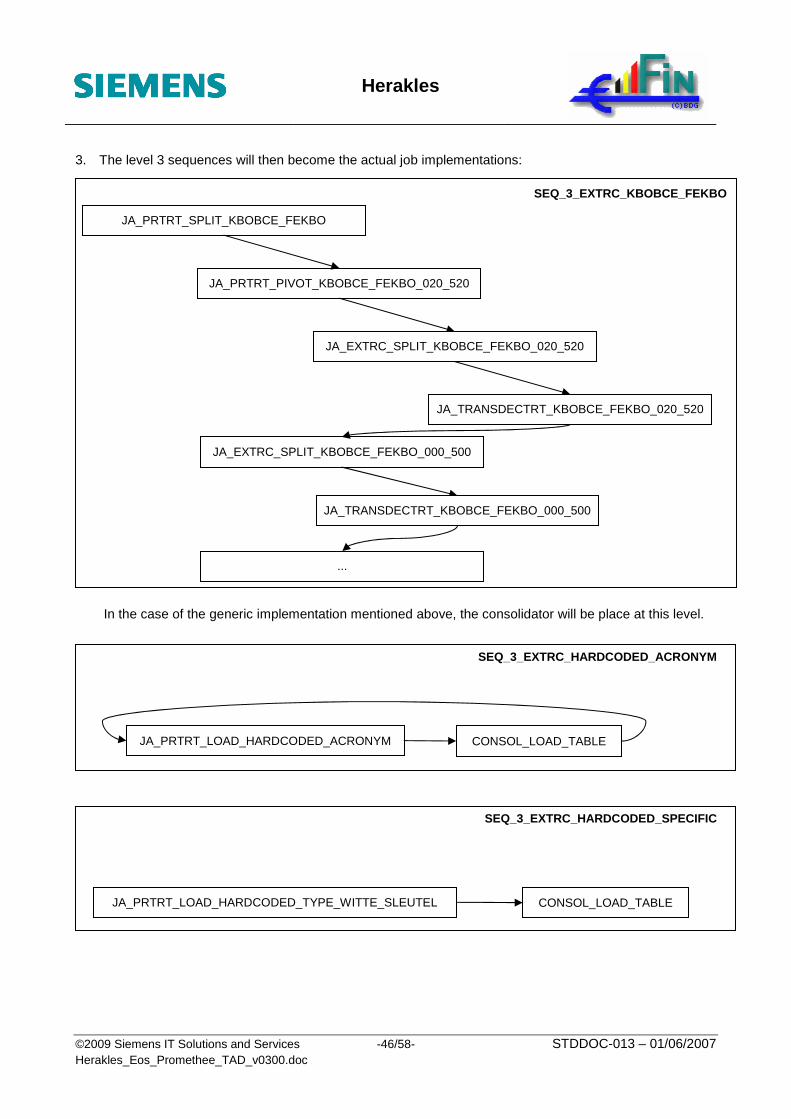
Herakles
©2009 Siemens IT Solutions and Services -46/58- STDDOC-013 – 01/06/2007 Herakles_Eos_Promethee_TAD_v0300.doc
3. The level 3 sequences will then become the actual job implementations:
In the case of the generic implementation mentioned above, the consolidator will be place at this level.
SEQ_3_EXTRC_HARDCODED_SPECIFIC
JA_PRTRT_LOAD_HARDCODED_TYPE_WITTE_SLEUTEL CONSOL_LOAD_TABLE
SEQ_3_EXTRC_HARDCODED_ACRONYM
JA_PRTRT_LOAD_HARDCODED_ACRONYM CONSOL_LOAD_TABLE
SEQ_3_EXTRC_KBOBCE_FEKBO
JA_PRTRT_SPLIT_KBOBCE_FEKBO
JA_PRTRT_PIVOT_KBOBCE_FEKBO_020_520
JA_EXTRC_SPLIT_KBOBCE_FEKBO_020_520
JA_TRANSDECTRT_KBOBCE_FEKBO_020_520
JA_EXTRC_SPLIT_KBOBCE_FEKBO_000_500
JA_TRANSDECTRT_KBOBCE_FEKBO_000_500
...

Herakles
©2009 Siemens IT Solutions and Services -47/58- STDDOC-013 – 01/06/2007 Herakles_Eos_Promethee_TAD_v0300.doc
4. The following level 4 sequence is called PRTRT in stead of EXTRC since it concerns the generic implementation of the jobs PRTRT_PIVOT_KBOBCE_CODE_GENERAL_*. In this level 4 sequence, the generic job is called multiple times, one after the other for the different “Targets” which define the actual functional job to be executed.
The component “EVAL_TARGET” will only generate the parameters for the looped execution of the generic job.
3.3.4.2. TRANSL
This translation step is the first target-centric step in the ETL-chain. At level 0 (V-Tom) there exists only one sequence:
Within this level 1 sequence, distinction will be made between the different identification and reference components. For the reference components, we came to generic implementations as discussed in 3.3.2.1.3 Sequence level 3: functional job execution. One more time a serial execution has had to be chosen.
SEQ_1_TRANSL
SEQ_2_IDENT_PERS
SEQ_2_IDENT_...
SEQ_2_MREF_GENERIC
SEQ_2_MREF_SPECIFIC
SEQ_2_MREF_CONTACT
SYNC_SA_DWH
CONSOL_ALL
EVAL_LOAD
JA_PRTRT_PIVOT_KBOBCE_CODE_GENERAL EVAL_TARGET
SEQ_4_PRTRT_PIVOT_KBOBCE_CODE_GENERAL
SEQ_1_TRANSL
Herakles scheduler
Cyclic launch SA

Herakles
©2009 Siemens IT Solutions and Services -48/58- STDDOC-013 – 01/06/2007 Herakles_Eos_Promethee_TAD_v0300.doc
Since the TRANSL is target-centric, no file evaluator or file consolidator is necessary at the level 2 but a target generator will be present (EVAL_TARGET).
The level 2 sequence for the identifications of individuals becomes:
The level 2 sequence for the generic reference components becomes:
SEQ_3_MREF_GENERIC_LOAD_ACRONYM
EVAL_TARGET
SEQ_3_MREF_GENERIC_TKSEARCH_ACRONYM_DATE
SEQ_2_MREF_GENERIC
SEQ_3_MREF_GENERIC_LOAD_NOACRONYM
SEQ_3_MREF_GENERIC_TKSEARCH_ACRONYM_NODATE
SEQ_3_MREF_GENERIC_TKSEARCH_NOACRONYM_DATE
SEQ_3_MREF_GENERIC_TKSEARCH_NOACRONYM_NODATE
SEQ_3_MREF_GENERIC_LOAD_4LANG SEQ_3_MREF_GENERIC_TKSEARCH_4LANG
SEQ_3_MREF_GENERIC_LOAD_4LANG_NATIO SEQ_3_MREF_GENERIC_TKSEARCH_4LANG_NATIO
SEQ_3_IDENT_ NPP EVAL_TARGET
SEQ_2_IDENT_PERS
SEQ_3_IDENT_RPM
SEQ_3_IDENT_...

Herakles
©2009 Siemens IT Solutions and Services -49/58- STDDOC-013 – 01/06/2007 Herakles_Eos_Promethee_TAD_v0300.doc
Level 3 sequences will be introduced for readability and manageability reasons.
JA_IDENT_LOAD_NPP_RRNN EVAL_LOAD_TARGET
SEQ_3_IDENT_NPP
JA_IDENT_LOAD_...
JA_IDENT_TKSEARCH_NPP_RRNN
JA_IDENT_TKSEARCH_...
JA_MREF_LOAD_ACRONYM
SEQ_3_MREF_GENERIC_LOAD_ACRONYM

Herakles
©2009 Siemens IT Solutions and Services -50/58- STDDOC-013 – 01/06/2007 Herakles_Eos_Promethee_TAD_v0300.doc
3.3.4.3. TRANSF_SRC
The transformation step is implemented for every source individually to increase the extensibility (a new source will not have impact on an existing TRANSF sequence). The level 0 (V-Tom) looks like:
In these SEQ_1_TRANSF_<SRC>, the load-id’s are determined and presented to the appropriate order.
When such a level 2 sequence is elaborated, this results in the following:
SEQ_3_TRANSF_KBOBCE_FEKBO EVAL_LOAD_TABLE
SEQ_2_TRANSF_KBOBCE
CONSOL_LOAD_TABLE
SEQ_2_TRANSF_KBOBCE EVAL_LOAD
SEQ_1_TRANSF_KBOBCE
CONSOL_LOAD
SEQ_1_TRANSF_HARCODED
SEQ_1_TRANSF_KBOBCE
SEQ_1_TRANSF_BTWTVA
SEQ_1_TRANSF_NPP
...
Herakles scheduler
Cyclic launch SA

Herakles
©2009 Siemens IT Solutions and Services -51/58- STDDOC-013 – 01/06/2007 Herakles_Eos_Promethee_TAD_v0300.doc
The level 3 sequence SEQ_3_TRANSF_KBOBCE_FEKBO then becomes (again in a serial modus):
3.3.4.4. LOAD_SA
Since the LOAD_SA step is target-centric, only 1 level 1 sequence will be disclosed towards V-Tom resulting in the following at the V-Tom level.
Also, because this is a target-centric step, we no longer have a source level granularity in the level 1 sequence itself.
The following picture depicts the chosen grouping of the sequences at the first sequence level where the differentiation is made between dimensions (DIM), bridges (BRIDGE) and facts (FACT) because of the dependencies that exist between them.
Since the LOAD_SA is target-centric, no file evaluator or file consolidator is necessary at the level 2 but a target generator will be present (EVAL_TARGET).
SEQ_1_LOAD_SA
SEQ_2_LOAD_SA_DIM
EVAL_TARGET
SEQ_2_LOAD_SA_BRIDGE SYNC_SA_DWH
CONSOL_ALL
SYNC_SA
SEQ_2_LOAD_SA_FACT
JA_LOAD_PREP_KBOBCE_FEKBO_000_500 JA_MERGE_KBOBCE_FEKBO_000_500
SEQ_3_TRANSF_KBOBCE _FEKBO
JA_LOAD_PREP_KBOBCE_FEKBO_010_510 JA_MERGE_KBOBCE_FEKBO_010_510
JA_LOAD_PREP_KBOBCE_FEKBO_... JA_MERGE_KBOBCE_FEKBO_...
SEQ_1_LOAD_SA
Herakles scheduler
Cyclic launch SA

Herakles
©2009 Siemens IT Solutions and Services -52/58- STDDOC-013 – 01/06/2007 Herakles_Eos_Promethee_TAD_v0300.doc
For readability and manageability reasons,
• the level 2 sequences split the dimensions, brigdes and facts per subject.
• the level 3 sequences starts level 4 sequences
• the level 4 sequences loop, for a particular job and target, over all inputs that are feeding it
SEQ_3_LOAD_SA_B_FACT
…
SEQ_2_LOAD_SA_ FACT
SEQ_3_LOAD_SA_G_FACT
JA_LOAD_SA_A0101_PERSONNE
SEQ_4_LOAD_SA_A0101_PERSONNE
SEQ_4_LOAD_SA_A0201_PERSONNE_PHYSIQUE
SEQ_4_LOAD_SA_A0202_PERSONNE_PHYSIQUE_ENTREPRISE
SEQ_4_LOAD_SA_A0301_PERSONNE_MORALE
SEQ_4_LOAD_SA_A0117_ETABLISSEMENT
SEQ_3_LOAD_SA_A_DIM
EVAL_TARGET
SEQ_4_LOAD_SA_A0101_PERSONNE
SEQ_3_LOAD_SA_A_BRIDGE
…
SEQ_2_LOAD_SA_ BRIDGE
SEQ_3_LOAD_SA_C_BRIDGE
SEQ_3_LOAD_SA_A_DIM
…
SEQ_2_LOAD_SA_ DIM

Herakles
©2009 Siemens IT Solutions and Services -53/58- STDDOC-013 – 01/06/2007 Herakles_Eos_Promethee_TAD_v0300.doc
3.3.5. Datawarehouse
3.3.5.1. LOAD_DWH
The final step in the chain is the actual loading of the data into the Datawarehouse. Contrary to the LOAD_SA, here the reference and identification tables are included.
From the point of view of V-Tom, we still have only one component.
Within this level 1 sequence we still have an evaluator containing the logic described in section 3.2.1 Herakles Master Scheduler and a consolidator. Following components are also present at this level: the synchronization between the Staging Area Outbox and the data warehouse and the cleaning of the landing zone and staging area in case of successful load.
SEQ_1_LOAD_DWH
SEQ_2_LOAD_DWH_ BRIDGE
SYNC_SA_DWH
SEQ_2_LOAD_DWH_DIM
CONSOL_LOAD SEQ_2_LOAD_DWH_IDENT
SEQ_2_LOAD_DWH_REF
EVAL_LOAD
CLEAN
SYNC_SA_DWH SEQ_2_LOAD_DWH_ FACT
SEQ_1_LOAD_DWH
Herakles scheduler
Cyclic launch DWH

Herakles
©2009 Siemens IT Solutions and Services -54/58- STDDOC-013 – 01/06/2007 Herakles_Eos_Promethee_TAD_v0300.doc
For readability and manageability reasons,
• the level 1 sequence split the jobs per identifications, referentials, dimensions, bridges and facts.
• the level 2 sequences, executes the jobs for the identifications, split the referential jobs according to their generic, not generic or contact character and split the dimensions and bridges per subject.
SEQ_3_LOAD_DWH_REF_GENERIC
SEQ_3_LOAD_DWH_REF_SPECIFIC
SEQ_3_LOAD_DWH_REF_CONTACT
SEQ_2_LOAD_DWH_REF
SEQ_3_LOAD_DWH_A_DIM
…
SEQ_2_LOAD_DWH_DIM
JA_LOAD_DWH_A0102_EXTERNE_IDENTIFICATIE_PERSONNE_MORALE
JA_LOAD_DWH_A0102_EXTERNE_IDENTIFICATIE_PERSONNE_PHYSIQUE
JA_LOAD_DWH_A0102_EXTERNE_IDENTIFICATIE_MANUEEL_PERSONNE
SEQ_2_LOAD_DWH_IDENT
SEQ_1_LOAD_DWH
SEQ_2_LOAD_DWH_ BRIDGE
SYNC_SA_DWH
SEQ_2_LOAD_DWH_DIM
CONSOL_LOAD SEQ_2_LOAD_DWH_IDENT
SEQ_2_LOAD_DWH_REF
EVAL_LOAD
CLEAN
SYNC_SA_DWH SEQ_2_LOAD_DWH_ FACT

Herakles
©2009 Siemens IT Solutions and Services -55/58- STDDOC-013 – 01/06/2007 Herakles_Eos_Promethee_TAD_v0300.doc
• the level 3 executes the jobs exept in the case of generic implementations where a level 4 is used
SEQ_3_LOAD_DWH_B_FACT
SEQ_3_LOAD_DWH_G_FACT
…
SEQ_2_LOAD_DWH_FACT
JA_LOAD_DWH_REF_GENERIC_ACRONYM_DATE
SEQ_4_LOAD_DWH_REF_GENERIC_ACRONYM
JA_LOAD_DWH_A0201_PERSONNE_PHYSIQUE
JA_LOAD_DWH_A0202_PERSONNE_PHYSIQUE_ENTREPRISE
JA_LOAD_DWH_A0301_PERSONNE_MORALE
JA_LOAD_DWH_A0117_ETABLISSEMENT
SEQ_3_LOAD_DWH_A_DIM
SEQ_4_LOAD_DWH_REF_GENERIC_ACRONYM
SEQ_4_LOAD_DWH_REF_GENERIC_NOACRONYM
SEQ_3_LOAD_DWH_REF_GENERIC
EVAL_TARGET
SEQ_3_LOAD_DWH_A_BRIDGE
SEQ_3_LOAD_DWH_C_BRIDGE
…
SEQ_2_LOAD_DWH_BRIDGE

Herakles
©2009 Siemens IT Solutions and Services -56/58- STDDOC-013 – 01/06/2007 Herakles_Eos_Promethee_TAD_v0300.doc
4. Architectural properties
4.1. Recoverablility / Restartability
These aspects are covered in the sections 3.1.3.3.3 Jobs directory, 3.1.3.3.4 Staging Area Outbox, 3.3.2.3 Data passing between jobs and 3.3.2.4 Stateful jobs.
4.2. Data Integrity / Reconciliation
These aspects are covered in the sections 3.1.2.2.3 Referential integrity, 3.3.2.1.1 Sequence level 1: load-id creation or evaluation, 3.3.2.1.2 Sequence level 2: file evaluation, 3.3.2.2.1 Record count tracing.
4.3. Monitoring
This aspect is covered in the sections 3.2.3 Herakles scheduler and 3.2.4 Sequence starter and monitoring.
4.4. Error handling
This aspect is covered in the section 3.3.2.2 Error handling and execution tracing.
4.5. Backup / Archiving
The backup aspect: see document [R14].
The archiving of the source files: see documents [R13] en [R14].

Herakles
©2009 Siemens IT Solutions and Services -57/58- STDDOC-013 – 01/06/2007 Herakles_Eos_Promethee_TAD_v0300.doc
5. Appendices
5.1. POC overview Section POC implemented ?
1. Introduction N/A2. Architectural overview N/A3. Architectural components
3.1. Storage Yes3.1.1. General overview N/A3.1.2. Framework Repository Yes
3.1.2.1. Design time repository (SAD) tables Yes3.1.2.2. Run time repository (SAR) tables Yes
3.1.3. File Systems Yes3.1.3.1. Ftp zone DCC3.1.3.2. Landing Zone Yes3.1.3.3. Staging Area Yes
3.1.3.3.1. Signatures Directory Yes3.1.3.3.2. Jobs directory Yes3.1.3.3.3. Staging Area Outbox Yes
3.1.4. Datawarehouse Yes3.1.4.1. Adding technical fields Yes3.1.4.2. Primary keys Yes3.1.4.3. Referential integrity Yes3.1.4.4. Indexing strategy No (first implement, test on actual volumes and ask DBA input)
3.2. Control Yes3.2.1. Herakles Master Scheduler Yes3.2.2. Ftp-zone scheduler DCC3.2.3. Herakles scheduler Yes3.2.4. Sequence starter and monitoring Yes
3.2.4.1. HP Openview Operations for Windows Yes3.2.4.2. Detailed Operational en functional monitoring Yes
3.3. Processing Yes3.3.1. General overview Yes3.3.2. Processing framework Yes
3.3.2.1. Technical grouping of job types Yes3.3.2.2. Sequence/Job execution tracing Yes3.3.2.3. Sequence level 1: Load ID Evaluation Yes3.3.2.4. Sequence level 2: File Evaluation Yes3.3.2.5. Sequence level 3: Functional Job execution Yes
3.3.2.5.1. Error handling and execution tracing Yes3.3.2.5.2. Record count tracing Yes3.3.2.5.3. Data passing between jobs Yes3.3.2.5.4. State full jobs Yes
3.3.2.6. Sequence level 4: Generic implementations Yes3.3.3. Landing zone Yes3.3.4. Staging Area Yes
3.3.4.1. EXTRC_SRC Yes3.3.4.2. TRANSL Yes3.3.4.3. TRANSF Yes3.3.4.4. LOAD_SA Yes
3.3.5. Datawarehouse Yes3.3.5.1. LOAD_DWH Yes
4. Architectural properties4.1. Recoverablility / Restartability Yes4.2. Data Integrity (reconciliation) Yes4.3. Monitoring Yes4.4. Error handling Yes4.5. Backup / Archiving Legato Team / DCC

Herakles
©2009 Siemens IT Solutions and Services -58/58- STDDOC-013 – 01/06/2007 Herakles_Eos_Promethee_TAD_v0300.doc
5.2. Performance figures
All jobs have been tuned (see also executed POC’s and mapping type technical specifications).
This tuning results in a significant improvement of the performance.
As an example, on 11/06/2007, after several enhancements, the initial extraction of KBO/BCE took 3 hours and 25 minutes.
The current initial extraction of KBO/BCE (implemented on a subset representing 40 % of the required processing power) runs in 30 minutes.
This means an improvement factor of more than 2.5 has been reached.
The same or higher gains have also been reached for other components.
Here has to be noted that the machine used in June 2007 (englfar3) was equipped with 24 processors, while the one used for the current runs (englfar2) is equipped with 8 processors.
For the daily incremental load of the first iteration of Eos, an improvement factor of minimum 2 is expected.
This factor has to be applied to the last figures of the incremental load, namely 8 hours and 6 minutes on 06/06/2007.