hengstler katalog
392
Encoders ■ Incremental ■ Absolute ■ Motor Feedback Systems Innovative products from your competent partner. Worldwide
-
Upload
vanja-durakovic -
Category
Documents
-
view
581 -
download
5
Transcript of hengstler katalog

Encoders■ Incremental
■ Absolute
■ MotorFeedback Systems
Innovative products from yourcompetent partner. Worldwide
E N C O D E R S C O U N T E R S I N D I C A T O R S R E L A Y S P R I N T E R S C U T T E R S
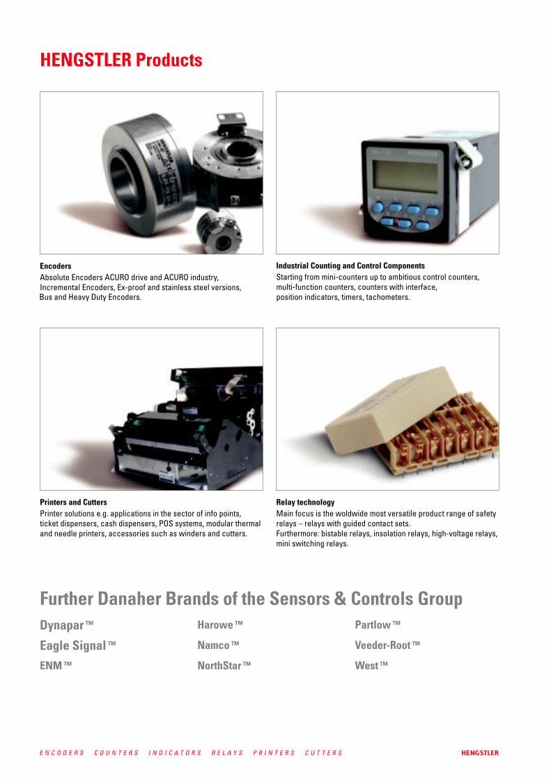
Bus and Heavy Duty Encoders.
1E N C O D E R S C O U N T E R S I N D I C A T O R S R E L A Y S P R I N T E R S C U T T E R S
Contents
Page
■ Variety and competence - HENGSTLER today 2■ Our service for you 4■ HENGSTLER produces worldwide 5
■ Products in this catalogue 6■ Applications 40
■ Incremental 44■ Absolute 72
■ Solid shaft versions 85■ Hollow shaft versions 104
■ ACURO industry 142BiSS/ SSI, Field bus systems, Parallel
■ Incremental 199■ Absolute 202
■ Incremental 236■ Absolute 241
■ Incremental 256
■ Incremental kit encoders 272
■ Hollow shaft encoders 281
■ Incremental encoders 283■ Absolute encoders 304■ Sine-wave encoders 317■ Resolvers 320
■ Position indicator for absolute encoders 323■ Encoder with shock module 326■ Flexible couplings, Mounting elements 327■ Connectors, cables 334■ Measuring wheels 341■ Displays, Technical Manuals, Software 343
■ Encoders basics: Output signals incremental encoders, 344maximum speed, protection class, examples of flange mounting
■ Basics of incremental encoders - output 349■ Basics of sine-wave encoders 354■ Basics of absolute encoders ACURO - interfaces 356■ Glossery of technical terms 378
■ Sales and Services International 384■ Terms and Conditions 387
GENERAL ASPECTS
PRODUCTS
HEAVY DUTY ENCODERS
STANDARD INDUSTRIALENCODERS INCREMENTAL
STANDARD INDUSTRIALENCODERS ABSOLUTESingle and Multiturn
STAINLESS INDUSTRIAL ENCODERS
EEX INDUSTRIAL ENCODERS
LIGHT DUTY ENCODERS
MOTOR FEEDBACK SYSTEMSFor Miniature DC & Stepper MotorsFor Asynchronous& DC MotorsFor AC Synchronous& BLDC Motors
ACCESSORIES
TECHNICAL BASICS
CONTACT & OTHERS
Gene
ral
aspe
cts

2 E N C O D E R S C O U N T E R S I N D I C A T O R S R E L A Y S P R I N T E R S C U T T E R S

3E N C O D E R S C O U N T E R S I N D I C A T O R S R E L A Y S P R I N T E R S C U T T E R S
TÜV-certified to ISO 9001:2000
ment and manufacturing.
printers since 1970, encoders since 1987,
Hengstler: Your Technology Partner
ders and relays. The product range is complemented by printers and cutters, withHengstler being the leading manufacturerfor cutters in Europe.

4 E N C O D E R S C O U N T E R S I N D I C A T O R S R E L A Y S P R I N T E R S C U T T E R S
(page 384).help. See chapter “Contact” (page 384).
is TÜV-certified to DIN EN ISO 9001:2000Reg.No. 12 100/104 32249 TMS.
Please visit also our website atwww.hengstler.com
(page 384).

5E N C O D E R S C O U N T E R S I N D I C A T O R S R E L A Y S P R I N T E R S C U T T E R S
HENGSTLER produces worldwideGermany – HENGSTLER GmbHAldingen
Slovakia – HENGSTLER sroKezmarok
USA – Danaher ControlsGurnee, Illinois
Brasil – Veeder Root do BrasilSao Paulo
China – Danaher ICG ChinaTianjin
Japan – Danaher ICG Japan Co.Osaka
6 E N C O D E R S C O U N T E R S I N D I C A T O R S R E L A Y S P R I N T E R S C U T T E R S
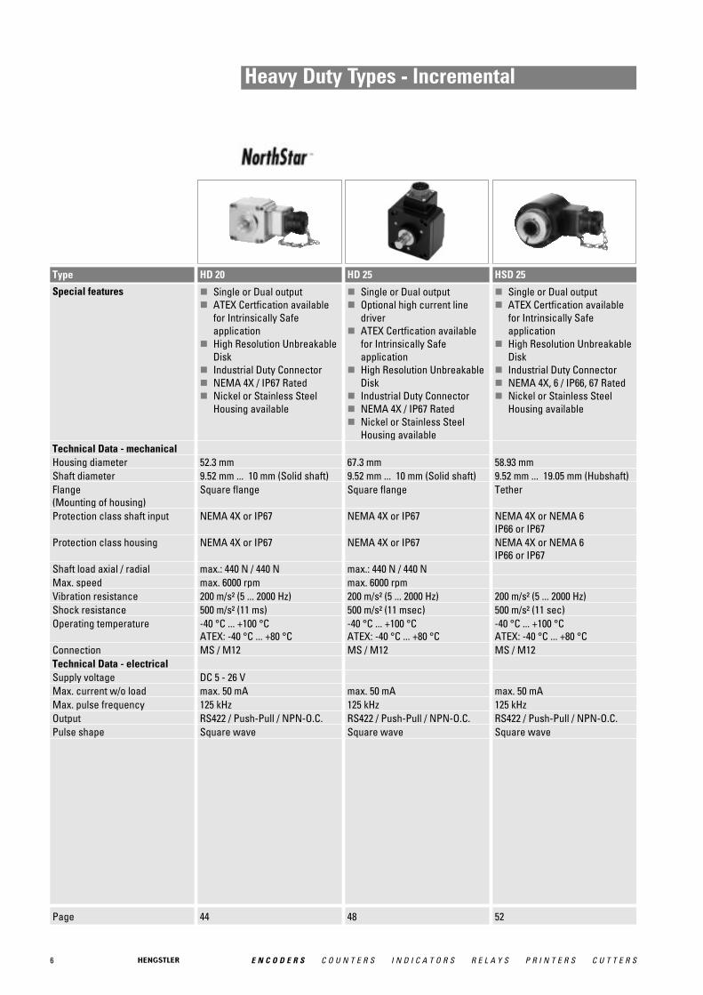
Heavy Duty Types - Incremental
Page 44 48 52
Type HD 20 HD 25 HSD 25
Special features � Single or Dual output� ATEX Certfication available
for Intrinsically Safe application
� High Resolution UnbreakableDisk
� Industrial Duty Connector� NEMA 4X / IP67 Rated� Nickel or Stainless Steel
Housing available
� Single or Dual output� Optional high current line
driver� ATEX Certfication available
for Intrinsically Safe application
� High Resolution UnbreakableDisk
� Industrial Duty Connector� NEMA 4X / IP67 Rated� Nickel or Stainless Steel
Housing available
� Single or Dual output� ATEX Certfication available
for Intrinsically Safe application
� High Resolution UnbreakableDisk
� Industrial Duty Connector� NEMA 4X, 6 / IP66, 67 Rated� Nickel or Stainless Steel
Housing available
Technical Data - mechanical Housing diameter 52.3 mm 67.3 mm 58.93 mmShaft diameter 9.52 mm ... 10 mm (Solid shaft) 9.52 mm ... 10 mm (Solid shaft) 9.52 mm ... 19.05 mm (Hubshaft)Flange (Mounting of housing)
Square flange Square flange Tether
Protection class shaft input NEMA 4X or IP67 NEMA 4X or IP67 NEMA 4X or NEMA 6IP66 or IP67
Protection class housing NEMA 4X or IP67 NEMA 4X or IP67 NEMA 4X or NEMA 6IP66 or IP67
Shaft load axial / radial max.: 440 N / 440 N max.: 440 N / 440 NMax. speed max. 6000 rpm max. 6000 rpmVibration resistance 200 m/s² (5 ... 2000 Hz) 200 m/s² (5 ... 2000 Hz) 200 m/s² (5 ... 2000 Hz)Shock resistance 500 m/s² (11 ms) 500 m/s² (11 msec) 500 m/s² (11 sec)Operating temperature -40 °C ... +100 °C
ATEX: -40 °C ... +80 °C-40 °C ... +100 °CATEX: -40 °C ... +80 °C
-40 °C ... +100 °CATEX: -40 °C ... +80 °C
Connection MS / M12 MS / M12 MS / M12Technical Data - electrical Supply voltage DC 5 - 26 VMax. current w/o load max. 50 mA max. 50 mA max. 50 mAMax. pulse frequency 125 kHz 125 kHz 125 kHzOutput RS422 / Push-Pull / NPN-O.C. RS422 / Push-Pull / NPN-O.C. RS422 / Push-Pull / NPN-O.C.Pulse shape Square wave Square wave Square wave
7E N C O D E R S C O U N T E R S I N D I C A T O R S R E L A Y S P R I N T E R S C U T T E R S
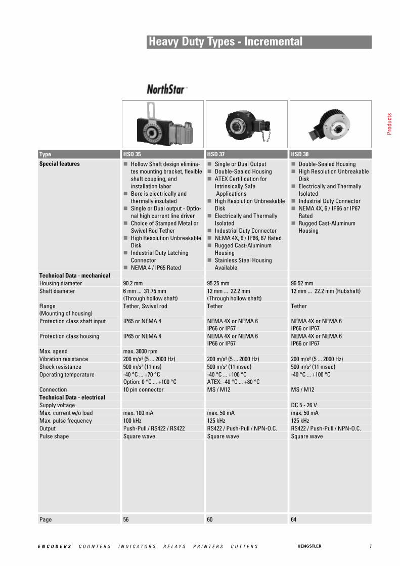
Heavy Duty Types - Incremental
Page 56 60 64
Type HSD 35 HSD 37 HSD 38
Special features � Hollow Shaft design elimina-tes mounting bracket, flexibleshaft coupling, and installation labor
� Bore is electrically and thermally insulated
� Single or Dual output - Optio-nal high current line driver
� Choice of Stamped Metal orSwivel Rod Tether
� High Resolution UnbreakableDisk
� Industrial Duty LatchingConnector
� NEMA 4 / IP65 Rated
� Single or Dual Output� Double-Sealed Housing� ATEX Certification for
Intrinsically SafeApplications
� High Resolution UnbreakableDisk
� Electrically and ThermallyIsolated
� Industrial Duty Connector� NEMA 4X, 6 / IP66, 67 Rated� Rugged Cast-Aluminum
Housing� Stainless Steel Housing
Available
� Double-Sealed Housing� High Resolution Unbreakable
Disk� Electrically and Thermally
Isolated� Industrial Duty Connector� NEMA 4X, 6 / IP66 or IP67
Rated� Rugged Cast-Aluminum
Housing
Technical Data - mechanical Housing diameter 90.2 mm 95.25 mm 96.52 mmShaft diameter 6 mm ... 31.75 mm
(Through hollow shaft)12 mm ... 22.2 mm (Through hollow shaft)
12 mm ... 22.2 mm (Hubshaft)
Flange (Mounting of housing)
Tether, Swivel rod Tether Tether
Protection class shaft input IP65 or NEMA 4 NEMA 4X or NEMA 6IP66 or IP67
NEMA 4X or NEMA 6IP66 or IP67
Protection class housing IP65 or NEMA 4 NEMA 4X or NEMA 6IP66 or IP67
NEMA 4X or NEMA 6IP66 or IP67
Max. speed max. 3600 rpmVibration resistance 200 m/s² (5 ... 2000 Hz) 200 m/s² (5 ... 2000 Hz) 200 m/s² (5 ... 2000 Hz)Shock resistance 500 m/s² (11 ms) 500 m/s² (11 msec) 500 m/s² (11 msec)Operating temperature -40 °C ... +70 °C
Option: 0 °C ... +100 °C-40 °C ... +100 °CATEX: -40 °C ... +80 °C
-40 °C ... +100 °C
Connection 10 pin connector MS / M12 MS / M12Technical Data - electrical Supply voltage DC 5 - 26 VMax. current w/o load max. 100 mA max. 50 mA max. 50 mAMax. pulse frequency 100 kHz 125 kHz 125 kHzOutput Push-Pull / RS422 / RS422 RS422 / Push-Pull / NPN-O.C. RS422 / Push-Pull / NPN-O.C.Pulse shape Square wave Square wave Square wave
Prod
ucts
8 E N C O D E R S C O U N T E R S I N D I C A T O R S R E L A Y S P R I N T E R S C U T T E R S
Heavy Duty Types - Incremental
Page 68
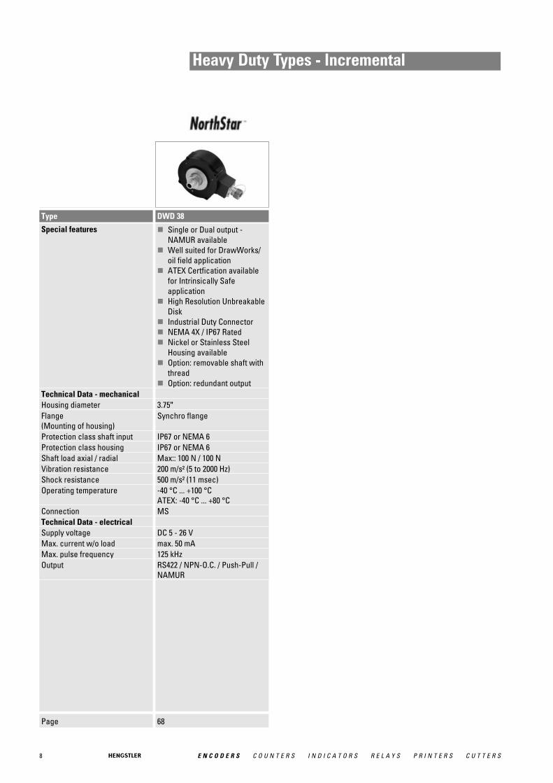
Type DWD 38
Special features � Single or Dual output -NAMUR available
� Well suited for DrawWorks/oil field application
� ATEX Certfication availablefor Intrinsically Safe application
� High Resolution UnbreakableDisk
� Industrial Duty Connector� NEMA 4X / IP67 Rated� Nickel or Stainless Steel
Housing available� Option: removable shaft with
thread� Option: redundant output
Technical Data - mechanical Housing diameter 3.75"Flange (Mounting of housing)
Synchro flange
Protection class shaft input IP67 or NEMA 6Protection class housing IP67 or NEMA 6Shaft load axial / radial Max:: 100 N / 100 NVibration resistance 200 m/s² (5 to 2000 Hz)Shock resistance 500 m/s² (11 msec)Operating temperature -40 °C ... +100 °C
ATEX: -40 °C ... +80 °CConnection MSTechnical Data - electrical Supply voltage DC 5 - 26 VMax. current w/o load max. 50 mAMax. pulse frequency 125 kHzOutput RS422 / NPN-O.C. / Push-Pull /
NAMUR
9E N C O D E R S C O U N T E R S I N D I C A T O R S R E L A Y S P R I N T E R S C U T T E R S
Heavy Duty Types - Absolute
Page 72 76 80
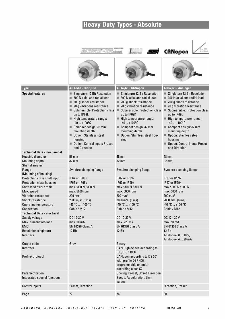
Type AR 62/63 - BiSS/SSI AR 62/63 - CANopen AR 62/63 - Analogue
Special features � Singleturn 12 Bit Resolution� 300 N axial and radial load� 200 g shock resistance� 20 g vibrations resistance� Submersible: Protection class
up to IP69k� High temperature range:
-40 ... +100°C� Compact design: 32 mm
mounting depth� Option: Stainless steel
housing� Option: Control inputs Preset
and Direction
� Singleturn 12 Bit Resolution� 300 N axial and radial load� 200 g shock resistance� 20 g vibration resistance� Submersible: Protection class
up to IP69K� High temperature range:
-40 ... +100°C� Compact design: 32 mm
mounting depth� Option: Stainless steel hou-
sing
� Singleturn 12 Bit Resolution� 300 N axial and radial load� 200 g shock resistance� 20 g vibration resistance� Submersible: Protection class
up to IP69k� High temperature range:
-40 ... +100°C� Compact design: 32 mm
mounting depth� Option: Stainless steel
housing� Option: Control inputs Preset
and DirectionTechnical Data - mechanical Housing diameter 58 mm 58 mm 58 mmMounting depth 32 mm 32 mm 32 mmShaft diameter Flange (Mounting of housing)
Synchro clamping flange Synchro clamping flange Synchro clamping flange
Protection class shaft input IP67 or IP69k IP67 or IP69k IP67 or IP69kProtection class housing IP67 or IP69k IP67 or IP69k IP67 or IP69kShaft load axial / radial max.: 300 N / 300 N max.: 300 N / 300 N max.: 300 N / 300 NMax. speed max. 5000 rpm max. 5000 rpm max. 5000 rpmVibration resistance 200 m/s² 200 m/s² 200 m/s²Shock resistance 2000 m/s² (6 ms) 2000 m/s² (6 ms) 2000 m/s² (6 ms)Operating temperature -40 °C ... +100 °C -40 °C ... +100 °C -40 °C ... +100 °CConnection Cable / M12 Cable / M12 Cable / M12Technical Data - electrical Supply voltage DC 10-30 V DC 10-30 V DC 17 - 30 VMax. current w/o load max. 50 mA max. 220 mA max. 50 mAEMC EN 61326 Class A EN 61326 Class A EN 61326 Class AResolution singleturn 12 Bit 12 Bit 12 BitInterface Analogue: 0 ... 10 V,
Analogue: 4 ... 20 mAOutput code Gray BinaryInterface CAN High-Speed according to
ISO/DIS 11898Profile/ protocol CANopen according to DS 301
with profile DSP 406, programmable encoder according class C2
Parametrization Scaling, Preset, Offset, DirectionIntegrated special functions Speed, Acceleration, Limit
valuesControl inputs Preset, Direction Direction, Preset
10 E N C O D E R S C O U N T E R S I N D I C A T O R S R E L A Y S P R I N T E R S C U T T E R S
Standard Industrial Types - IncrementalSolid Shaft
Page 85 90 94
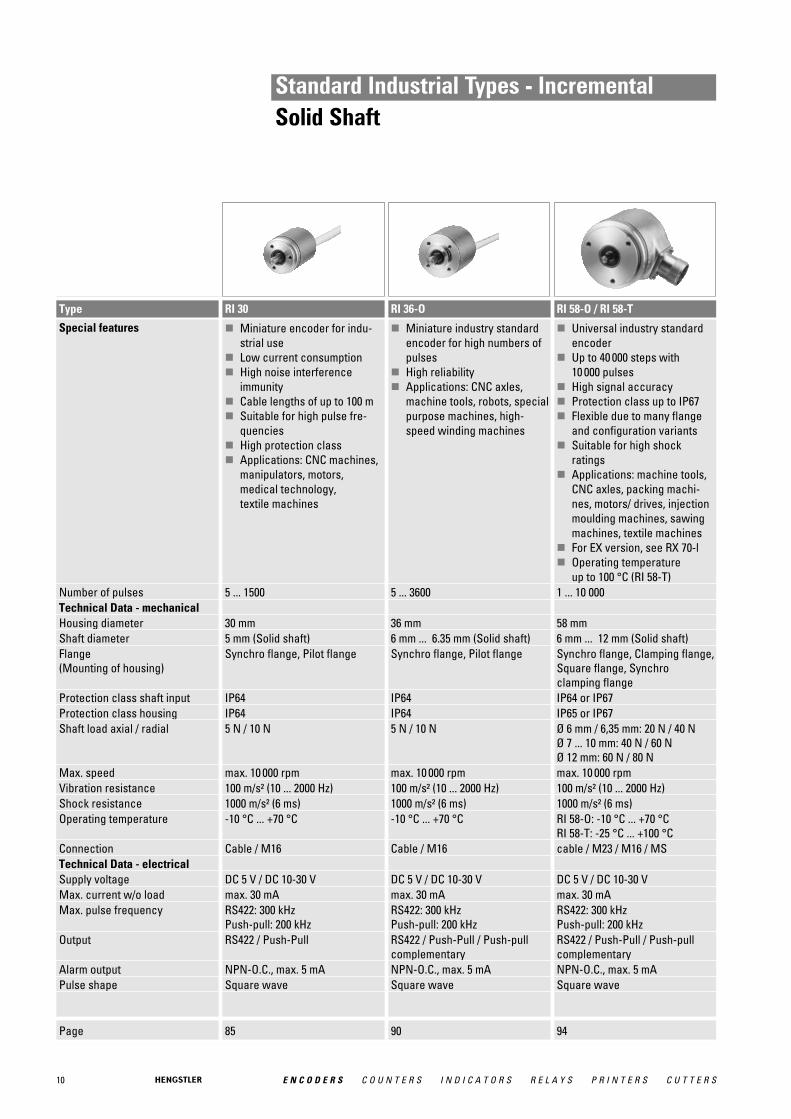
Type RI 30 RI 36-O RI 58-O / RI 58-T
Special features � Miniature encoder for indu-strial use
� Low current consumption� High noise interference
immunity� Cable lengths of up to 100 m� Suitable for high pulse fre-
quencies� High protection class� Applications: CNC machines,
manipulators, motors, medical technology, textile machines
� Miniature industry standardencoder for high numbers ofpulses
� High reliability� Applications: CNC axles,
machine tools, robots, specialpurpose machines, high-speed winding machines
� Universal industry standardencoder
� Up to 40 000 steps with 10 000 pulses
� High signal accuracy� Protection class up to IP67� Flexible due to many flange
and configuration variants� Suitable for high shock
ratings� Applications: machine tools,
CNC axles, packing machi-nes, motors/ drives, injectionmoulding machines, sawingmachines, textile machines
� For EX version, see RX 70-l� Operating temperature
up to 100 °C (RI 58-T)Number of pulses 5 ... 1500 5 ... 3600 1 ... 10 000Technical Data - mechanical Housing diameter 30 mm 36 mm 58 mmShaft diameter 5 mm (Solid shaft) 6 mm ... 6.35 mm (Solid shaft) 6 mm ... 12 mm (Solid shaft)Flange (Mounting of housing)
Synchro flange, Pilot flange Synchro flange, Pilot flange Synchro flange, Clamping flange,Square flange, Synchro clamping flange
Protection class shaft input IP64 IP64 IP64 or IP67Protection class housing IP64 IP64 IP65 or IP67Shaft load axial / radial 5 N / 10 N 5 N / 10 N Ø 6 mm / 6,35 mm: 20 N / 40 N
Ø 7 ... 10 mm: 40 N / 60 NØ 12 mm: 60 N / 80 N
Max. speed max. 10 000 rpm max. 10 000 rpm max. 10 000 rpmVibration resistance 100 m/s² (10 ... 2000 Hz) 100 m/s² (10 ... 2000 Hz) 100 m/s² (10 ... 2000 Hz)Shock resistance 1000 m/s² (6 ms) 1000 m/s² (6 ms) 1000 m/s² (6 ms)Operating temperature -10 °C ... +70 °C -10 °C ... +70 °C RI 58-O: -10 °C ... +70 °C
RI 58-T: -25 °C ... +100 °CConnection Cable / M16 Cable / M16 cable / M23 / M16 / MSTechnical Data - electrical Supply voltage DC 5 V / DC 10-30 V DC 5 V / DC 10-30 V DC 5 V / DC 10-30 VMax. current w/o load max. 30 mA max. 30 mA max. 30 mAMax. pulse frequency RS422: 300 kHz
Push-pull: 200 kHzRS422: 300 kHzPush-pull: 200 kHz
RS422: 300 kHzPush-pull: 200 kHz
Output RS422 / Push-Pull RS422 / Push-Pull / Push-pullcomplementary
RS422 / Push-Pull / Push-pullcomplementary
Alarm output NPN-O.C., max. 5 mA NPN-O.C., max. 5 mA NPN-O.C., max. 5 mAPulse shape Square wave Square wave Square wave

11E N C O D E R S C O U N T E R S I N D I C A T O R S R E L A Y S P R I N T E R S C U T T E R S
Standard Industrial Types - IncrementalHollow Shaft
Page 104 109 113
Type RI 36-H RI 58-H RI 58-D / RI 58TD
Special features � Miniature industry encoderfor high number of pulses
� Short mounting length� Easy mounting procedure� Applications: motors,
machine tools, robots, automated SMD equipment
� Through hollow shaft� High accuracy by means of
integrated flexible coupling� Safe shaft mounting� Applications: textile machi-
nes, motors, drives, copiers
� Direct mounting without coupling
� Flexible hollow shaft designup to diameter 14 mm
� Through hollow shaft or asend shaft (blind shaft)
� Easy installation by means ofclamping shaft or blind shaft
� Short overall length of 33 mm� Fixing of flage by means of a
stator coupling or set screw� Various shaft versions� Applications: actuators,
motors� Operating temperature up to
100 °C (RI 58TD)Number of pulses 5 ... 3600 1 ... 5000 1 ... 5000Technical Data - mechanical Housing diameter 36 mm 58 mm 58 mmShaft diameter 4 mm ... 10 mm (Hubshaft) 10 mm ... 12 mm (Hubshaft) 10 mm ... 12 mm
(Through hollow shaft)10 mm ... 14 mm (Hubshaft)
Flange (Mounting of housing)
Tether Synchro flange Synchro flange
Protection class shaft input IP64 IP64 IP64Protection class housing IP64 IP64 Through hollow shaft - D: IP64
Hubshaft - E,F: IP65Max. speed max. 10 000 rpm max. 3000 rpm max. 4000 rpmVibration resistance 100 m/s² (10 ... 2000 Hz) 10 g = 100 m/s² (10 ... 2000 Hz) 10 g = 100 m/s² (10 ... 2000 Hz)Shock resistance 1000 m/s² (6 ms) 100 g = 1000 m/s² (6 ms) 100 g = 1000 m/s² (6 ms)Operating temperature -10 °C ... +70 °C -10 °C ... +70 °C RI 58-D: -10 °C ... +70 °C
RI 58TD: -25 °C ... +100 °CConnection Cable Cable Cable / M23Technical Data - electrical Supply voltage DC 5 V / DC 10-30 V DC 5 V / DC 10-30 V DC 5 V / DC 10-30 VMax. current w/o load max. 30 mA max. 30 mA max. 30 mAMax. pulse frequency RS422: 300 kHz
Push-pull: 200 kHzRS422: 300 kHzPush-pull: 200 kHz
RS422: 300 kHzPush-pull: 200 kHz
Output RS422 / Push-Pull / Push-pullcomplementary
RS422 / Push-Pull / Push-pullcomplementary
RS422 / Push-Pull / Push-pullcomplementary
Alarm output NPN-O.C., max. 5 mA NPN-O.C., max. 5 mAPulse shape Square wave Square wave Square wave

12 E N C O D E R S C O U N T E R S I N D I C A T O R S R E L A Y S P R I N T E R S C U T T E R S
Standard Industrial Types - IncrementalHollow Shaft
Page 122 128
Type RI 58-G / RI 58TG RI 58-F
Special features � Direct mounting without cou-pling
� Through hollow shaft Ø 14mm and 15 mm
� Easy installation by means ofclamping ring
� Fixing of flage by means of astator coupling or set screw
� Applications: actuators,motors
� Incremental hollow shaftencoder
� Up to 10 000 ppr� Through hollow shaft and
hubshaft up to 12 mm (14 mm optional)
� Optimized stator coupling� Applications: Feedback for
asynchronous motors, industrial applications
Number of pulses 50 ... 2500 1 ... 10 000Technical Data - mechanical Housing diameter 58 mm 58 mmShaft diameter 14 mm ... 15 mm
(Through hollow shaft)6 mm ... 12 mm (Hubshaft)6 mm ... 12 mm (Through hollow shaft)
Flange (Mounting of housing)
Synchro flange Tether
Protection class shaft input IP64 IP64Protection class housing IP64 Through hollow shaft - D: IP64
Hubshaft - F: IP67Max. speed max. 4000 rpm max. 6000 rpmVibration resistance 10 g = 100 m/s² (10 ... 2000 Hz) 100 m/s²Shock resistance 100 g = 1000 m/s² (6 ms) 1000 m/s²Operating temperature RI 58-G: -10 °C ... +70 °C
RI 58TG: -10 °C ... +100 °C-10 °C ... +70 °C
Connection Cable Cable / M23Technical Data - electrical Supply voltage DC 5 V / DC 10-30 V DC 5 V / DC 10-30 VMax. current w/o load max. 30 mA max. 30 mAMax. pulse frequency RS422: 300 kHz
Push-pull: 200 kHzOutput RS422 / Push-Pull / Push-pull
complementaryRS422 / Push-Pull / Push-pullcomplementary
Alarm output NPN-O.C., max. 5 mAPulse shape Square wave

13E N C O D E R S C O U N T E R S I N D I C A T O R S R E L A Y S P R I N T E R S C U T T E R S
Standard Industrial Types - IncrementalHollow Shaft
Page 132 136
Type RI 76TD RI 80-E
Special features � Through hollow shaft Ø 15 bis 42 mm
� Outside diameter only 76 mm� Easy installation by means of
clamping ring front or rear� Operating temperature up to
100 °C� Applications: motors, printing
machines, lifts
� Incremental� 30 - 45 mm hollow shaft� Rugged mechanical design� Unbreakable disc� Integrated diagnostic system� Wide voltage range
DC 5 - 30 V� Isolated shaft
Number of pulses 1 ... 10 000 1024, 2048, 2500, 4096, 5000, 10 000 (other number of pulseson request)
Technical Data - mechanical Housing diameter 76 mm 100 mmShaft diameter 15 mm ... 40 mm (Hub shaft) 10 mm ... 12 mm
(Through hollow shaft)Flange (Mounting of housing)
Tether Tether
Protection class shaft input IP40 or IP64 IP50 or IP64Protection class housing IP50 (IP65 optional) IP50 or IP64Max. speed max. 1800 rpm max. 1500 rpmVibration resistance 10 g = 100 m/s² (10 ... 2000 Hz)Shock resistance 100 g = 1000 m/s² (6 ms)Operating temperature -25 °C ... +100 °C -25 °C ... +85 °CConnection Cable Sub-DTechnical Data - electrical Supply voltage DC 5 V / DC 10-30 V DC 5 V ±10 % / DC 5-30 VMax. current w/o load max. 35 mA max. 35 mAMax. pulse frequency RS422: 300 kHz
Push-pull: 200 kHzRS422: 600 kHzPush-pull: 200 kHz
Output RS422 / Push-Pull / Push-pullcomplementary
RS422 / Push-Pull / Push-pullcomplementary
Alarm output NPN-O.C., max. 5 mA NPN-O.C., max. 5 mAPulse shape Square wave Square wave
14 E N C O D E R S C O U N T E R S I N D I C A T O R S R E L A Y S P R I N T E R S C U T T E R S
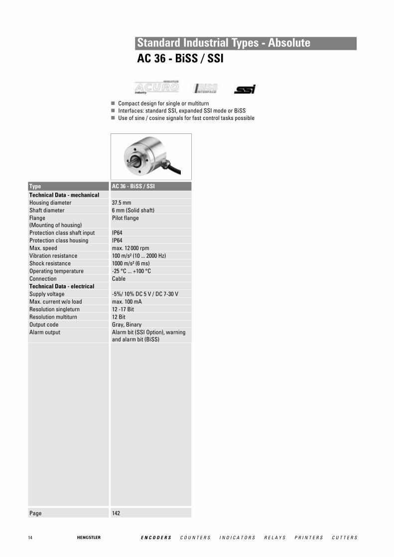
Standard Industrial Types - AbsoluteAC 36 - BiSS / SSI
� Compact design for single or multiturn� Interfaces: standard SSI, expanded SSI mode or BiSS� Use of sine / cosine signals for fast control tasks possible
Page 142
Type AC 36 - BiSS / SSITechnical Data - mechanical Housing diameter 37.5 mmShaft diameter 6 mm (Solid shaft)Flange (Mounting of housing)
Pilot flange
Protection class shaft input IP64Protection class housing IP64Max. speed max. 12 000 rpmVibration resistance 100 m/s² (10 ... 2000 Hz)Shock resistance 1000 m/s² (6 ms)Operating temperature -25 °C ... +100 °CConnection CableTechnical Data - electrical Supply voltage -5%/ 10% DC 5 V / DC 7-30 VMax. current w/o load max. 100 mAResolution singleturn 12 -17 BitResolution multiturn 12 BitOutput code Gray, BinaryAlarm output Alarm bit (SSI Option), warning
and alarm bit (BiSS)
15E N C O D E R S C O U N T E R S I N D I C A T O R S R E L A Y S P R I N T E R S C U T T E R S
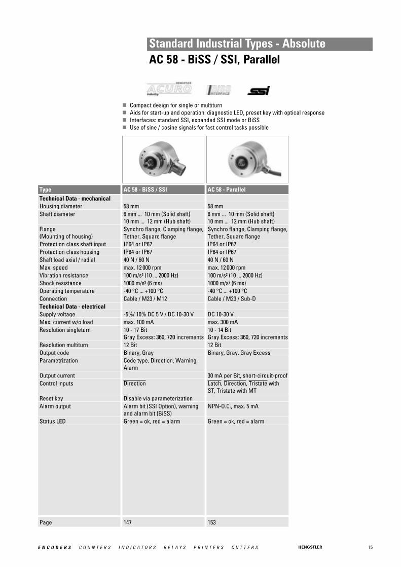
Standard Industrial Types - AbsoluteAC 58 - BiSS / SSI, Parallel
� Compact design for single or multiturn� Aids for start-up and operation: diagnostic LED, preset key with optical response� Interfaces: standard SSI, expanded SSI mode or BiSS� Use of sine / cosine signals for fast control tasks possible
Page 147 153
Type AC 58 - BiSS / SSI AC 58 - ParallelTechnical Data - mechanical Housing diameter 58 mm 58 mmShaft diameter 6 mm ... 10 mm (Solid shaft)
10 mm ... 12 mm (Hub shaft)6 mm ... 10 mm (Solid shaft)10 mm ... 12 mm (Hub shaft)
Flange (Mounting of housing)
Synchro flange, Clamping flange,Tether, Square flange
Synchro flange, Clamping flange,Tether, Square flange
Protection class shaft input IP64 or IP67 IP64 or IP67Protection class housing IP64 or IP67 IP64 or IP67Shaft load axial / radial 40 N / 60 N 40 N / 60 NMax. speed max. 12 000 rpm max. 12 000 rpmVibration resistance 100 m/s² (10 ... 2000 Hz) 100 m/s² (10 ... 2000 Hz)Shock resistance 1000 m/s² (6 ms) 1000 m/s² (6 ms)Operating temperature -40 °C ... +100 °C -40 °C ... +100 °CConnection Cable / M23 / M12 Cable / M23 / Sub-DTechnical Data - electrical Supply voltage -5%/ 10% DC 5 V / DC 10-30 V DC 10-30 VMax. current w/o load max. 100 mA max. 300 mAResolution singleturn 10 - 17 Bit
Gray Excess: 360, 720 increments10 - 14 BitGray Excess: 360, 720 increments
Resolution multiturn 12 Bit 12 BitOutput code Binary, Gray Binary, Gray, Gray ExcessParametrization Code type, Direction, Warning,
AlarmOutput current 30 mA per Bit, short-circuit-proofControl inputs Direction Latch, Direction, Tristate with
ST, Tristate with MTReset key Disable via parameterizationAlarm output Alarm bit (SSI Option), warning
and alarm bit (BiSS)NPN-O.C., max. 5 mA
Status LED Green = ok, red = alarm Green = ok, red = alarm
16 E N C O D E R S C O U N T E R S I N D I C A T O R S R E L A Y S P R I N T E R S C U T T E R S
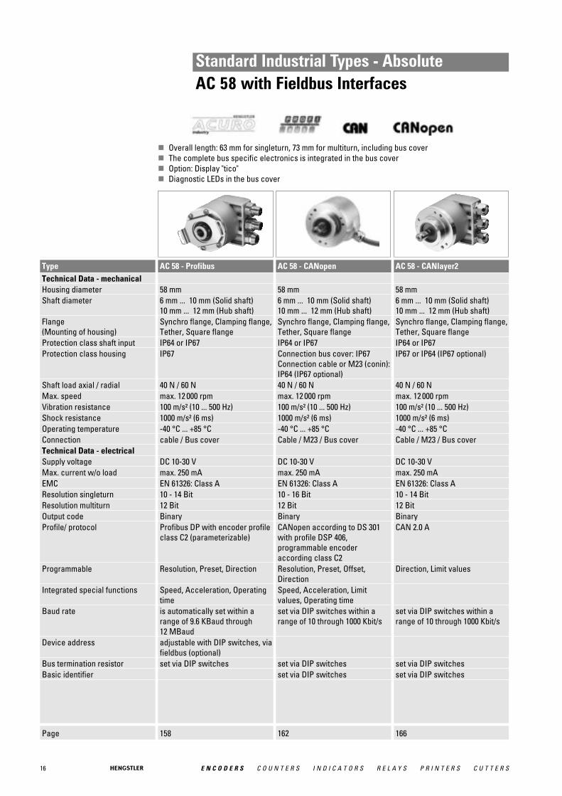
Standard Industrial Types - AbsoluteAC 58 with Fieldbus Interfaces
� Overall length: 63 mm for singleturn, 73 mm for multiturn, including bus cover� The complete bus specific electronics is integrated in the bus cover� Option: Display "tico"� Diagnostic LEDs in the bus cover
Page 158 162 166
Type AC 58 - Profibus AC 58 - CANopen AC 58 - CANlayer2Technical Data - mechanical Housing diameter 58 mm 58 mm 58 mmShaft diameter 6 mm ... 10 mm (Solid shaft)
10 mm ... 12 mm (Hub shaft)6 mm ... 10 mm (Solid shaft)10 mm ... 12 mm (Hub shaft)
6 mm ... 10 mm (Solid shaft)10 mm ... 12 mm (Hub shaft)
Flange (Mounting of housing)
Synchro flange, Clamping flange,Tether, Square flange
Synchro flange, Clamping flange,Tether, Square flange
Synchro flange, Clamping flange,Tether, Square flange
Protection class shaft input IP64 or IP67 IP64 or IP67 IP64 or IP67Protection class housing IP67 Connection bus cover: IP67
Connection cable or M23 (conin):IP64 (IP67 optional)
IP67 or IP64 (IP67 optional)
Shaft load axial / radial 40 N / 60 N 40 N / 60 N 40 N / 60 NMax. speed max. 12 000 rpm max. 12 000 rpm max. 12 000 rpmVibration resistance 100 m/s² (10 ... 500 Hz) 100 m/s² (10 ... 500 Hz) 100 m/s² (10 ... 500 Hz)Shock resistance 1000 m/s² (6 ms) 1000 m/s² (6 ms) 1000 m/s² (6 ms)Operating temperature -40 °C ... +85 °C -40 °C ... +85 °C -40 °C ... +85 °CConnection cable / Bus cover Cable / M23 / Bus cover Cable / M23 / Bus coverTechnical Data - electrical Supply voltage DC 10-30 V DC 10-30 V DC 10-30 VMax. current w/o load max. 250 mA max. 250 mA max. 250 mAEMC EN 61326: Class A EN 61326: Class A EN 61326: Class AResolution singleturn 10 - 14 Bit 10 - 16 Bit 10 - 14 BitResolution multiturn 12 Bit 12 Bit 12 BitOutput code Binary Binary BinaryProfile/ protocol Profibus DP with encoder profile
class C2 (parameterizable)CANopen according to DS 301with profile DSP 406, programmable encoder according class C2
CAN 2.0 A
Programmable Resolution, Preset, Direction Resolution, Preset, Offset, Direction
Direction, Limit values
Integrated special functions Speed, Acceleration, Operatingtime
Speed, Acceleration, Limitvalues, Operating time
Baud rate is automatically set within arange of 9.6 KBaud through 12 MBaud
set via DIP switches within arange of 10 through 1000 Kbit/s
set via DIP switches within arange of 10 through 1000 Kbit/s
Device address adjustable with DIP switches, viafieldbus (optional)
Bus termination resistor set via DIP switches set via DIP switches set via DIP switchesBasic identifier set via DIP switches set via DIP switches

17E N C O D E R S C O U N T E R S I N D I C A T O R S R E L A Y S P R I N T E R S C U T T E R S
Standard Industrial Types - AbsoluteAC 58 with Fieldbus Interfaces
� Overall length: 63 mm for singleturn, 73 mm for multiturn, including bus cover� The complete bus specific electronics is integrated in the bus cover� Option: Display "tico"� Diagnostic LEDs in the bus cover
Page 170 174 178
Type AC 58 - DeviceNet AC 58 - Interbus AC 58 - SUCOnetTechnical Data - mechanical Housing diameter 58 mm 58 mm 58 mmShaft diameter 6 mm ... 10 mm (Solid shaft)
10 mm ... 12 mm (Hub shaft)6 mm ... 10 mm (Solid shaft)10 mm ... 12 mm (Hub shaft)
6 mm ... 10 mm (Solid shaft)10 mm ... 12 mm (Hubshaft)
Flange (Mounting of housing)
Synchro flange, Clamping flange,Tether, Square flange
Synchro flange, Clamping flange,Tether, Square flange
Synchro flange, Clamping flange,Tether, Square flange
Protection class shaft input IP64 or IP67 IP64 or IP67 IP64 or IP67Protection class housing IP67 Connection bus cover: IP67
Connection cable or M23 (conin):IP64 (IP67 optional)
IP64
Shaft load axial / radial 40 N / 60 N 40 N / 60 N 40 N / 60 NMax. speed max. 12 000 rpm max. 12 000 rpm max. 12 000 rpmVibration resistance 100 m/s² (10 ... 500 Hz) 100 m/s² (10 ... 500 Hz) 100 m/s²Shock resistance 1000 m/s² (6 ms) 1000 m/s² (6 ms) 1000 m/s²Operating temperature -40 °C ... +85 °C -40 °C ... +70 °C -10 °C ... +60 °CConnection cable / Bus cover cable / Bus cover / M23 CableTechnical Data - electrical Supply voltage DC 10-30 V DC 10-30 V DC 10-30 VMax. current w/o load max. 250 mA max. 250 mA max. 200 mAEMC Noise emission according to
EN 50081-2, Immunity to inter-ference according to EN 50082-2
Noise emission according to EN 50081-2, Immunity to inter-ference according to EN 50082-2
EMC EN 61326: Class A EN 61326: class AResolution singleturn 10 - 14 Bit 10 - 12 Bit 10 - 13 BitResolution multiturn 12 Bit 12 Bit 12 BitOutput code Binary 32 Bit binary BinaryInterface CAN High-Speed according to
ISO/DIS 11898, CAN specifi-cation 2.0 A (11-Bit-Identifier)
Profile/ protocol DeviceNet according to Rev. 2.0,progammable encoder
ENCOM-Profil K3 = ID-Code 37,K2 = ID-Code 36
SUCOnet-K1 or Hengstler-G1
Programmable Resolution, Preset, Direction Resolution, Preset, Offset, Direction
Resolution, Direction
Output current max. 4.5 A for bus cover with 2xM23, max. 2 A for all otherconnections
Baud rate set via DIP switches to 125, 250,500 KBaud
500 KBaud
Address switch set via DIP switchesBus termination resistor set via DIP switches set via DIP switchesMAC-ID set via DIP switches
18 E N C O D E R S C O U N T E R S I N D I C A T O R S R E L A Y S P R I N T E R S C U T T E R S
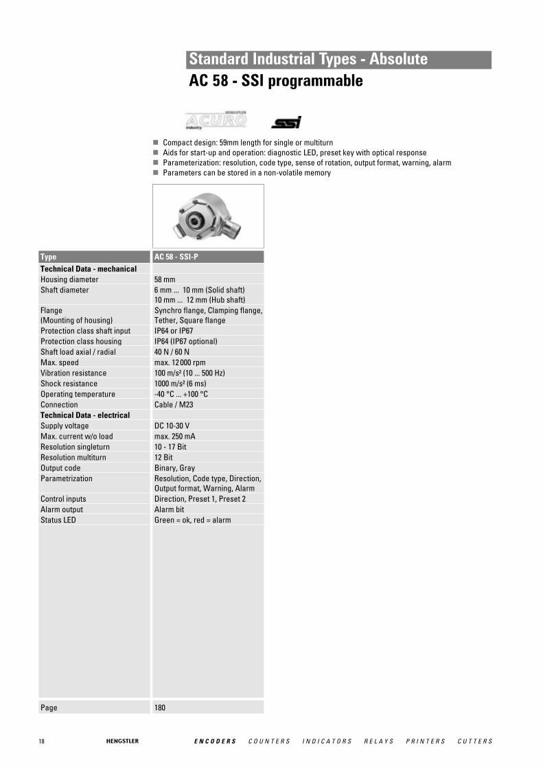
Standard Industrial Types - AbsoluteAC 58 - SSI programmable
� Compact design: 59mm length for single or multiturn� Aids for start-up and operation: diagnostic LED, preset key with optical response� Parameterization: resolution, code type, sense of rotation, output format, warning, alarm� Parameters can be stored in a non-volatile memory
Page 180
Type AC 58 - SSI-PTechnical Data - mechanical Housing diameter 58 mmShaft diameter 6 mm ... 10 mm (Solid shaft)
10 mm ... 12 mm (Hub shaft)Flange (Mounting of housing)
Synchro flange, Clamping flange,Tether, Square flange
Protection class shaft input IP64 or IP67Protection class housing IP64 (IP67 optional)Shaft load axial / radial 40 N / 60 NMax. speed max. 12 000 rpmVibration resistance 100 m/s² (10 ... 500 Hz)Shock resistance 1000 m/s² (6 ms)Operating temperature -40 °C ... +100 °CConnection Cable / M23Technical Data - electrical Supply voltage DC 10-30 VMax. current w/o load max. 250 mAResolution singleturn 10 - 17 BitResolution multiturn 12 BitOutput code Binary, GrayParametrization Resolution, Code type, Direction,
Output format, Warning, AlarmControl inputs Direction, Preset 1, Preset 2Alarm output Alarm bitStatus LED Green = ok, red = alarm

19E N C O D E R S C O U N T E R S I N D I C A T O R S R E L A Y S P R I N T E R S C U T T E R S
Standard Industrial Types - AbsoluteAC 110 - BiSS / SSI
� Hollow shaft up to 50 mm� Singleturn up to 17 Bit
Page 194
Type AC 110 - BiSS / SSITechnical Data - mechanical Housing diameter 110 mmShaft diameter 50 mm (Hub shaft)Protection class shaft input IP50 or IP64Protection class housing IP40 or IP64Max. speed max. 1500 rpmVibration resistance 100 m/s² (10 ... 500 Hz)Shock resistance 1000 m/s² (6 ms)Operating temperature -20 °C ... +70 °CConnection Cable / M23Technical Data - electrical Supply voltage -5%/ 10% DC 5 V / DC 10-30 VMax. current w/o load max. 120 mAResolution singleturn 10 - 17 BitOutput code Binary, GrayAlarm output Alarm bit (SSI Option), warning
and alarm bit (BiSS)
20 E N C O D E R S C O U N T E R S I N D I C A T O R S R E L A Y S P R I N T E R S C U T T E R S
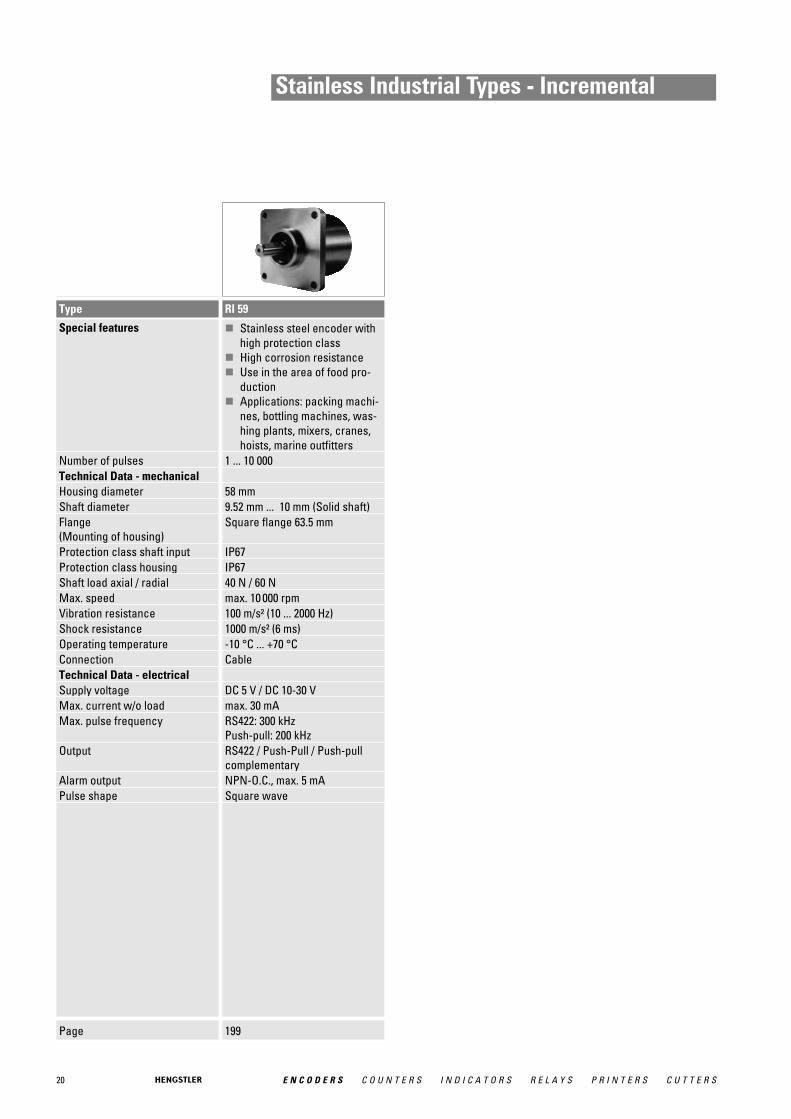
Stainless Industrial Types - Incremental
Page 199
Type RI 59
Special features � Stainless steel encoder withhigh protection class
� High corrosion resistance� Use in the area of food pro-
duction� Applications: packing machi-
nes, bottling machines, was-hing plants, mixers, cranes,hoists, marine outfitters
Number of pulses 1 ... 10 000Technical Data - mechanical Housing diameter 58 mmShaft diameter 9.52 mm ... 10 mm (Solid shaft)Flange (Mounting of housing)
Square flange 63.5 mm
Protection class shaft input IP67Protection class housing IP67Shaft load axial / radial 40 N / 60 NMax. speed max. 10 000 rpmVibration resistance 100 m/s² (10 ... 2000 Hz)Shock resistance 1000 m/s² (6 ms)Operating temperature -10 °C ... +70 °CConnection CableTechnical Data - electrical Supply voltage DC 5 V / DC 10-30 VMax. current w/o load max. 30 mAMax. pulse frequency RS422: 300 kHz
Push-pull: 200 kHzOutput RS422 / Push-Pull / Push-pull
complementaryAlarm output NPN-O.C., max. 5 mAPulse shape Square wave
21E N C O D E R S C O U N T E R S I N D I C A T O R S R E L A Y S P R I N T E R S C U T T E R S
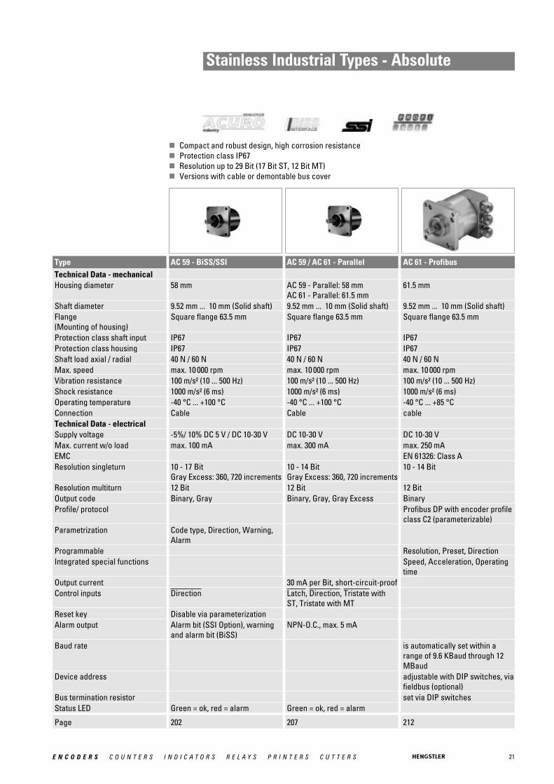
Stainless Industrial Types - Absolute
� Compact and robust design, high corrosion resistance� Protection class IP67� Resolution up to 29 Bit (17 Bit ST, 12 Bit MT)� Versions with cable or demontable bus cover
Page 202 207 212
Type AC 59 - BiSS/SSI AC 59 / AC 61 - Parallel AC 61 - ProfibusTechnical Data - mechanical Housing diameter 58 mm AC 59 - Parallel: 58 mm
AC 61 - Parallel: 61.5 mm61.5 mm
Shaft diameter 9.52 mm ... 10 mm (Solid shaft) 9.52 mm ... 10 mm (Solid shaft) 9.52 mm ... 10 mm (Solid shaft)Flange (Mounting of housing)
Square flange 63.5 mm Square flange 63.5 mm Square flange 63.5 mm
Protection class shaft input IP67 IP67 IP67Protection class housing IP67 IP67 IP67Shaft load axial / radial 40 N / 60 N 40 N / 60 N 40 N / 60 NMax. speed max. 10 000 rpm max. 10 000 rpm max. 10 000 rpmVibration resistance 100 m/s² (10 ... 500 Hz) 100 m/s² (10 ... 500 Hz) 100 m/s² (10 ... 500 Hz)Shock resistance 1000 m/s² (6 ms) 1000 m/s² (6 ms) 1000 m/s² (6 ms)Operating temperature -40 °C ... +100 °C -40 °C ... +100 °C -40 °C ... +85 °CConnection Cable Cable cableTechnical Data - electrical Supply voltage -5%/ 10% DC 5 V / DC 10-30 V DC 10-30 V DC 10-30 VMax. current w/o load max. 100 mA max. 300 mA max. 250 mAEMC EN 61326: Class AResolution singleturn 10 - 17 Bit
Gray Excess: 360, 720 increments10 - 14 BitGray Excess: 360, 720 increments
10 - 14 Bit
Resolution multiturn 12 Bit 12 Bit 12 BitOutput code Binary, Gray Binary, Gray, Gray Excess BinaryProfile/ protocol Profibus DP with encoder profile
class C2 (parameterizable)Parametrization Code type, Direction, Warning,
AlarmProgrammable Resolution, Preset, DirectionIntegrated special functions Speed, Acceleration, Operating
timeOutput current 30 mA per Bit, short-circuit-proofControl inputs Direction Latch, Direction, Tristate with
ST, Tristate with MTReset key Disable via parameterizationAlarm output Alarm bit (SSI Option), warning
and alarm bit (BiSS)NPN-O.C., max. 5 mA
Baud rate is automatically set within arange of 9.6 KBaud through 12MBaud
Device address adjustable with DIP switches, viafieldbus (optional)
Bus termination resistor set via DIP switchesStatus LED Green = ok, red = alarm Green = ok, red = alarm
22 E N C O D E R S C O U N T E R S I N D I C A T O R S R E L A Y S P R I N T E R S C U T T E R S
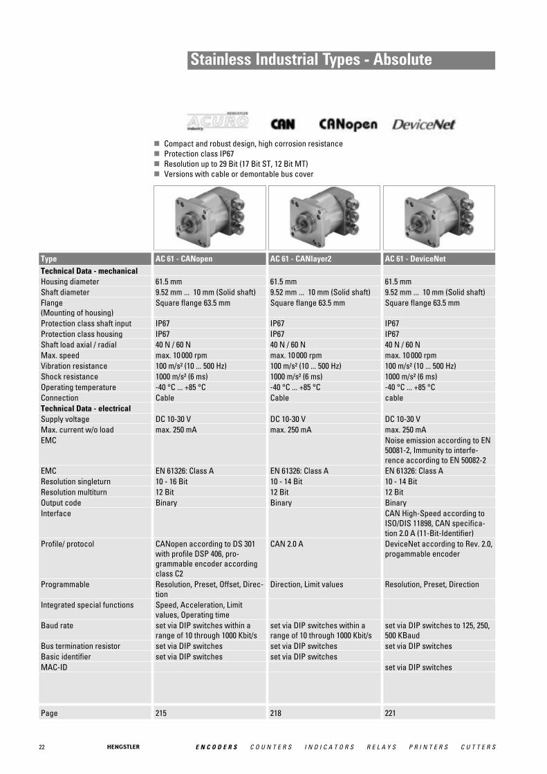
Stainless Industrial Types - Absolute
� Compact and robust design, high corrosion resistance� Protection class IP67� Resolution up to 29 Bit (17 Bit ST, 12 Bit MT)� Versions with cable or demontable bus cover
Page 215 218 221
Type AC 61 - CANopen AC 61 - CANlayer2 AC 61 - DeviceNetTechnical Data - mechanical Housing diameter 61.5 mm 61.5 mm 61.5 mmShaft diameter 9.52 mm ... 10 mm (Solid shaft) 9.52 mm ... 10 mm (Solid shaft) 9.52 mm ... 10 mm (Solid shaft)Flange (Mounting of housing)
Square flange 63.5 mm Square flange 63.5 mm Square flange 63.5 mm
Protection class shaft input IP67 IP67 IP67Protection class housing IP67 IP67 IP67Shaft load axial / radial 40 N / 60 N 40 N / 60 N 40 N / 60 NMax. speed max. 10 000 rpm max. 10 000 rpm max. 10 000 rpmVibration resistance 100 m/s² (10 ... 500 Hz) 100 m/s² (10 ... 500 Hz) 100 m/s² (10 ... 500 Hz)Shock resistance 1000 m/s² (6 ms) 1000 m/s² (6 ms) 1000 m/s² (6 ms)Operating temperature -40 °C ... +85 °C -40 °C ... +85 °C -40 °C ... +85 °CConnection Cable Cable cableTechnical Data - electrical Supply voltage DC 10-30 V DC 10-30 V DC 10-30 VMax. current w/o load max. 250 mA max. 250 mA max. 250 mAEMC Noise emission according to EN
50081-2, Immunity to interfe-rence according to EN 50082-2
EMC EN 61326: Class A EN 61326: Class A EN 61326: Class AResolution singleturn 10 - 16 Bit 10 - 14 Bit 10 - 14 BitResolution multiturn 12 Bit 12 Bit 12 BitOutput code Binary Binary BinaryInterface CAN High-Speed according to
ISO/DIS 11898, CAN specifica-tion 2.0 A (11-Bit-Identifier)
Profile/ protocol CANopen according to DS 301with profile DSP 406, pro-grammable encoder accordingclass C2
CAN 2.0 A DeviceNet according to Rev. 2.0,progammable encoder
Programmable Resolution, Preset, Offset, Direc-tion
Direction, Limit values Resolution, Preset, Direction
Integrated special functions Speed, Acceleration, Limitvalues, Operating time
Baud rate set via DIP switches within arange of 10 through 1000 Kbit/s
set via DIP switches within arange of 10 through 1000 Kbit/s
set via DIP switches to 125, 250,500 KBaud
Bus termination resistor set via DIP switches set via DIP switches set via DIP switchesBasic identifier set via DIP switches set via DIP switchesMAC-ID set via DIP switches

23E N C O D E R S C O U N T E R S I N D I C A T O R S R E L A Y S P R I N T E R S C U T T E R S
Stainless Industrial Types - Absolute
� Compact and robust design, high corrosion resistance� Protection class IP67� Resolution up to 29 Bit (17 Bit ST, 12 Bit MT)� Versions with cable or demontable bus cover
Page 224 227
Type AC 61 - Interbus AC 61 - SSI-PTechnical Data - mechanical Housing diameter 61.5 mm 61.5 mmShaft diameter 9.52 mm ... 10 mm (Solid shaft) 9.52 mm ... 10 mm (Solid shaft)Flange (Mounting of housing)
Square flange 63.5 mm Square flange 63.5 mm
Protection class shaft input IP67 IP67Protection class housing IP67 IP67Shaft load axial / radial 40 N / 60 N 40 N / 60 NMax. speed max. 10 000 rpm max. 10 000 rpmVibration resistance 100 m/s² (10 ... 500 Hz) 100 m/s² (10 ... 500 Hz)Shock resistance 1000 m/s² (6 ms) 1000 m/s² (6 ms)Operating temperature -40 °C ... +70 °C -40 °C ... +70 °CConnection cable CableTechnical Data - electrical Supply voltage DC 10-30 V DC 10-30 VMax. current w/o load max. 250 mA max. 250 mAEMC Noise emission according to EN
50081-2, Immunity to interfe-rence according to EN 50082-2
Resolution singleturn 10 - 12 Bit 10 - 17 BitResolution multiturn 12 Bit 12 BitOutput code 32 Bit binary Binary, GrayProfile/ protocol ENCOM-Profil K3 = ID-Code 37,
K2 = ID-Code 36Parametrization Resolution, Code type, Direction,
Output format, Warning, AlarmProgrammable Resolution, Preset, Offset, Direc-
tionOutput current max. 4.5 A for bus cover with 2x
M23, max. 2 A for all otherconnections
Control inputs Direction, Preset 1, Preset 2Alarm output Alarm bitBaud rate 500 KBaudStatus LED Green = ok, red = alarm
24 E N C O D E R S C O U N T E R S I N D I C A T O R S R E L A Y S P R I N T E R S C U T T E R S
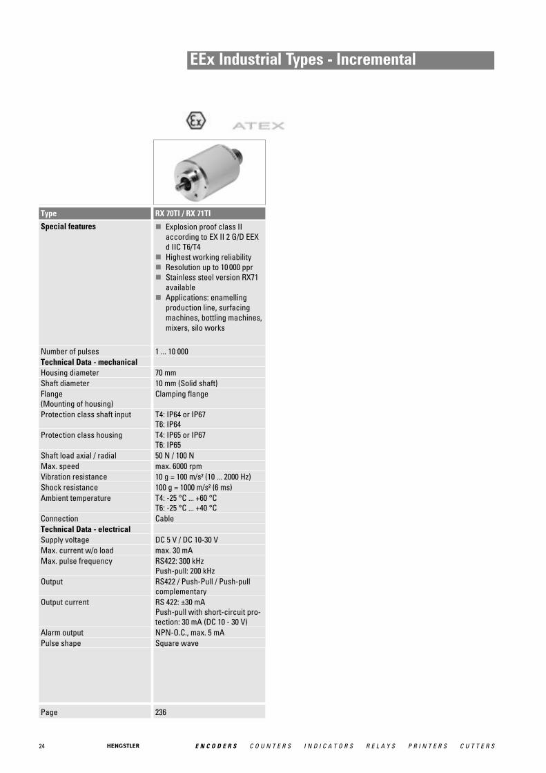
EEx Industrial Types - Incremental
Page 236
Type RX 70TI / RX 71TI
Special features � Explosion proof class IIaccording to EX II 2 G/D EEXd IIC T6/T4
� Highest working reliability� Resolution up to 10 000 ppr � Stainless steel version RX71
available� Applications: enamelling
production line, surfacingmachines, bottling machines,mixers, silo works
Number of pulses 1 ... 10 000Technical Data - mechanical Housing diameter 70 mmShaft diameter 10 mm (Solid shaft)Flange (Mounting of housing)
Clamping flange
Protection class shaft input T4: IP64 or IP67T6: IP64
Protection class housing T4: IP65 or IP67T6: IP65
Shaft load axial / radial 50 N / 100 NMax. speed max. 6000 rpmVibration resistance 10 g = 100 m/s² (10 ... 2000 Hz)Shock resistance 100 g = 1000 m/s² (6 ms)Ambient temperature T4: -25 °C ... +60 °C
T6: -25 °C ... +40 °CConnection CableTechnical Data - electrical Supply voltage DC 5 V / DC 10-30 VMax. current w/o load max. 30 mAMax. pulse frequency RS422: 300 kHz
Push-pull: 200 kHzOutput RS422 / Push-Pull / Push-pull
complementaryOutput current RS 422: ±30 mA
Push-pull with short-circuit pro-tection: 30 mA (DC 10 - 30 V)
Alarm output NPN-O.C., max. 5 mAPulse shape Square wave

25E N C O D E R S C O U N T E R S I N D I C A T O R S R E L A Y S P R I N T E R S C U T T E R S
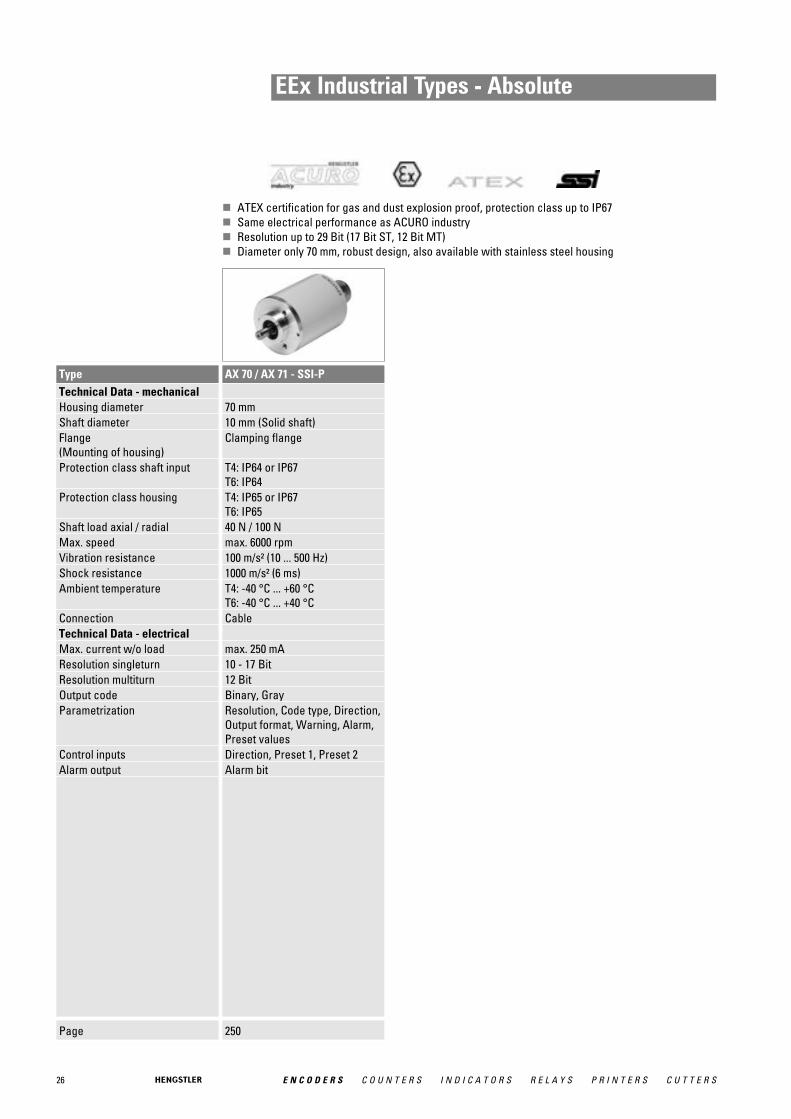
EEx Industrial Types - Absolute
� ATEX certification for gas and dust explosion proof, protection class up to IP67� Same electrical performance as ACURO industry� Resolution up to 29 Bit (17 Bit ST, 12 Bit MT)� Diameter only 70 mm, robust design, also available with stainless steel housing
Page 241 244 247
Type AX 70 / AX 71 - SSI AX 70 / AX 71 - Profibus AX 70 / AX 71 - CANopenTechnical Data - mechanical Housing diameter 70 mm 70 mm 70 mmShaft diameter 10 mm (Solid shaft) 10 mm (Solid shaft) 10 mm (Solid shaft)Flange (Mounting of housing)
Clamping flange Clamping flange Clamping flange
Protection class shaft input T4: IP64 or IP67T6: IP64
T4: IP64 or IP67T6: IP64
T4: IP64 or IP67T6: IP64
Protection class housing T4: IP65 or IP67T6: IP65
T4: IP65 or IP67T6: IP65
T4: IP65 or IP67T6: IP65
Shaft load axial / radial 40 N / 100 N 40 N / 100 N 40 N / 100 NMax. speed max. 6000 rpm max. 6000 rpm max. 6000 rpmVibration resistance 100 m/s² (10 ... 500 Hz) 100 m/s² (10 ... 500 Hz) 100 m/s² (10 ... 500 Hz)Shock resistance 1000 m/s² (6 ms) 1000 m/s² (6 ms) 1000 m/s² (6 ms)Ambient temperature T4: -40 °C ... +60 °C
T6: -40 °C ... +40 °CT4: -40 °C ... +60 °CT6: -40 °C ... +40 °C
T4: -40 °C ... +60 °CT6: -40 °C ... +40 °C
Connection Cable Cable CableTechnical Data - electrical Max. current w/o load max. 250 mA max. 250 mA max. 250 mAResolution singleturn 10 - 17 Bit 10 - 14 Bit 10 - 14 BitResolution multiturn 12 Bit 12 Bit 12 BitOutput code Binary, Gray Binary BinaryProfile/ protocol Profibus DP with encoder profile
class C2 (parameterizable)CANopen according to DS 301with profile DSP 406, pro-grammable encoder accordingclass C2
Parametrization Resolution, Preset, Direction Resolution, Preset, Offset, Direc-tion
Integrated special functions Speed, Acceleration, Operatingtime
Speed, Acceleration, Roteryaxis, Limit values, Operating time
Control inputs DirectionAlarm output Alarm bit (SSI Option)Baud rate is automatically set within a
range of 9.6 KBaud through 12MBaud
Device address set via BusBus termination resistor external mounting external mounting
26 E N C O D E R S C O U N T E R S I N D I C A T O R S R E L A Y S P R I N T E R S C U T T E R S
EEx Industrial Types - Absolute
� ATEX certification for gas and dust explosion proof, protection class up to IP67� Same electrical performance as ACURO industry� Resolution up to 29 Bit (17 Bit ST, 12 Bit MT)� Diameter only 70 mm, robust design, also available with stainless steel housing
Page 250
Type AX 70 / AX 71 - SSI-PTechnical Data - mechanical Housing diameter 70 mmShaft diameter 10 mm (Solid shaft)Flange (Mounting of housing)
Clamping flange
Protection class shaft input T4: IP64 or IP67T6: IP64
Protection class housing T4: IP65 or IP67T6: IP65
Shaft load axial / radial 40 N / 100 NMax. speed max. 6000 rpmVibration resistance 100 m/s² (10 ... 500 Hz)Shock resistance 1000 m/s² (6 ms)Ambient temperature T4: -40 °C ... +60 °C
T6: -40 °C ... +40 °CConnection CableTechnical Data - electrical Max. current w/o load max. 250 mAResolution singleturn 10 - 17 BitResolution multiturn 12 BitOutput code Binary, GrayParametrization Resolution, Code type, Direction,
Output format, Warning, Alarm,Preset values
Control inputs Direction, Preset 1, Preset 2Alarm output Alarm bit

27E N C O D E R S C O U N T E R S I N D I C A T O R S R E L A Y S P R I N T E R S C U T T E R S
Light Duty Types - Incremental
Page 256 259 262
Type PC 9 / PC 9S RI 32 RI 38
Special features � Provides digital control inputsfrom operators´s panel
� Bidirectional squarewavesignal outputs
� Up to 512 increments� Continuous and reversible
rotation� Non-contacting� Operating temperature
-40 ... 100 °C
� Replacement for type Typ RISand RI 31
� The economical encoder forsmall appliances
� High efficiency by means ofball bearing
� Small torque� Applications: laboratory
equipment, training equip-ment, crimping machines,tampon printing machines,miniature grinding machines
� Replacement for type RI 39� Encoder for universal instal-
lation by means of front/backpanel mounting
� High efficiency by means ofball bearing
� Small torque� Applications: FHP motors,
laboratory equipment, label-ling machines, plotters,length measuring machines
Number of pulses 100 ... 512 5 ... 1500 5 ... 1024Technical Data - mechanical Housing diameter PC 9: 22 mm
PC 9S: 22.86 mm30 mm 39 mm
Shaft diameter 3.175 mm ... 6.35 mm 5 mm ... 6 mm (Solid shaft) 6 mm (Solid shaft)Flange (Mounting of housing)
Pilot flange Square flange
Protection class shaft input IP40 IP40Protection class housing IP50 IP50Shaft load axial / radial 1/8" shaft: 4 N / 27 N
1/4" shaft: 4 N / 4 N5 N / 10 N 5 N / 10 N
Max. speed max. 6000 rpm max. 10 000 rpmVibration resistance 100 m/s² (10 ... 2000 Hz) 100 m/s² (10 ... 2000 Hz)Shock resistance 1000 m/s² (6 ms) 1000 m/s² (6 ms)Operating temperature -40 °C ... +100 °C -10 °C ... +60 °C -10 °C ... +60 °CConnection PC 9: 10 pole header
PC 9S: 5 pole headerCable Cable
Technical Data - electrical Supply voltage DC 5 V ±10 % DC 5 V / DC 10-30 V DC 5 V / DC 10-30 VMax. current w/o load max. 30 mA max. 30 mAMax. pulse frequency 200 kHz DC 5 V: 300 kHz
DC 10 - 30 V: 200 kHzDC 5 V: 300 kHzDC 10 - 30 V: 200 kHz
Output Push-Pull Push-PullOutput signals min. 2.5 V high (VOH), max. 0.5 V
low (VOL)Output current PC 9: 3 mA sink/source (25 °C),
2 mA (100 °C)PC 9S: 6 mA sink/source (25 °C),4 mA (100 °C)
Alarm output NPN-O.C., max. 5 mA NPN-O.C., max. 5 mAPulse shape Square wave Square wave Square wave
28 E N C O D E R S C O U N T E R S I N D I C A T O R S R E L A Y S P R I N T E R S C U T T E R S
Light Duty Types - Incremental
Page 265 268
Type RI 41 RI 42
Special features � Replacement for type RIM� Economical miniature enco-
der� Up to 14,400 steps with 3,600
pulses� High mechanical efficiency� Applications: wood working
machines, FHP motors, graphic machines, tablerobots
� Economical miniatureencoder
� High protection IP65� Output Push-pull or NPN-O.C.� High mechanical efficiency� Applications:
textile machinery
Number of pulses 5 ... 3600 5 ... 1024Technical Data - mechanical Housing diameter 40 mm 40 mmShaft diameter 6 mm (Solid shaft) 6 mm (Solid shaft)Flange (Mounting of housing)
Pilot flange Pilot flange
Protection class shaft input IP40 IP64Protection class housing IP50 IP65Shaft load axial / radial 5 N / 10 N 5 N / 10 NMax. speed max. 10 000 rpm max. 10 000 rpmVibration resistance 100 m/s² (10 ... 2000 Hz) 100 m/s² (10 ... 2000 Hz)Shock resistance 1000 m/s² (6 ms) 1000 m/s² (6 ms)Operating temperature -10 °C ... +70 °C 0 °C ... +60 °CConnection Cable CableTechnical Data - electrical Supply voltage DC 5 V / DC 10-30 V DC 5 V / DC 10-30 V / DC 10-24 VMax. current w/o load max. 30 mA max. 40 mAMax. pulse frequency DC 5 V: 300 kHz
DC 10 - 30 V: 200 kHzDC 5 V: 300 kHzDC 10 - 30 V: 200 kHzDC 10 - 24 V: 50 kHz
Output Push-Pull Push-Pull / Push-pull comple-mentary / NPN-O.C.
Alarm output NPN-O.C., max. 5 mA NPN-O.C., max. 5 mAPulse shape Square wave Square wave
29E N C O D E R S C O U N T E R S I N D I C A T O R S R E L A Y S P R I N T E R S C U T T E R S
Motor Feedback - Kit EncodersMiniature, DC & Stepper Motors
Page 272 275 278
Type E 9 M 9 M 14
Special features � Ideal for position and speedsensing in small machinesand actuators
� Low power standby mode isideal for battery powereddevices
� Max. output frequency: 200 kHz
� Resolution to 512 lines/rev
� Ideal for position and speedsensing in small machinesand actuators
� Max. output frequency: 200 kHz
� Resolution to 512 lines/rev
� Ideal economical feedbackdevice for servo and stepmotors
� Short axial length and compact 1.5 inch diameter
� Easy "snap-on" installation� High resolution to
1024 lines/rev and 200 kHzbandwidth
� Max. output frequency: 200 kHz
� Replacement for HP 5540� CE qualified
Number of pulses 100 ... 512 100 ... 512 200 ... 1024Technical Data - mechanical Housing diameter 22 mm 22 mm 38 mmMounting depth 20 mm 14.8 mm 17.2 mmShaft diameter 1.5 mm ... 3.962 mm (Hub shaft) 1.5 mm ... 3.962 mm (Hub shaft) 3 mm ... 19.05 mm (Hub shaft)Max. speed max. 12 000 rpm max. 12 000 rpm max. 12 000 rpmOperating temperature -40 °C ... +100 °C -40 °C ... +100 °C -40 °C ... +100 °CConnection 10 pole header 5 pole header 5 pole headerTechnical Data - electrical Supply voltage DC 5 V ±10 % DC 5 V ±10 % DC 5 V ±10 % Max. current w/o load max. 10 mA max. 10 mA max. 10 mAMax. pulse frequency 200 kHz 200 kHz 200 kHzOutput TTL TTL TTLOutput signals min. 2.5 V high (VOH),
max. 0.5 V low (VOL)min. 2.5 V high, max. 0.5 V low
min. 2.5 V high, max. 0.5 V low
Output current 3 mA sink/source (25°C), 2 mA (100°C)
6 mA (25°C), 4 mA (100°C) 6 mA (25°C), 4 mA (100°C)
Pulse shape Square wave
30 E N C O D E R S C O U N T E R S I N D I C A T O R S R E L A Y S P R I N T E R S C U T T E R S
Motorfeedback - Incremental TypesAsynchronous & DC Motors
Page 104 113 122
Type RI 36-H RI 58-D / RI 58TD RI 58-G / RI 58TG
Special features � Miniature industry encoderfor high number of pulses
� Short mounting length� Easy mounting procedure� Applications: motors,
machine tools, robots, automated SMD equipment
� Direct mounting without coupling
� Flexible hollow shaft designup to diameter 14 mm
� Through hollow shaft or asend shaft (blind shaft)
� Easy installation by means ofclamping shaft or blind shaft
� Short overall length of 33 mm� Fixing of flage by means of a
stator coupling or set screw� Various shaft versions� Applications: actuators,
motors� Operating temperature up to
100 °C (RI 58TD)
� Direct mounting without coupling
� Through hollow shaft Ø 14 mm and 15 mm
� Easy installation by means ofclamping ring
� Fixing of flage by means of astator coupling or set screw
� Applications: actuators,motors
Number of pulses 5 ... 3600 1 ... 5000 50 ... 2500Technical Data - mechanical Housing diameter 36 mm 58 mm 58 mmShaft diameter 4 mm ... 10 mm (Hubshaft) 10 mm ... 12 mm
(Through hollow shaft)10 mm ... 14 mm (Hubshaft)
14 mm ... 15 mm (Through hollow shaft)
Flange (Mounting of housing)
Tether Synchro flange Synchro flange
Protection class shaft input IP64 IP64 IP64Protection class housing IP64 Through hollow shaft - D: IP64
Hubshaft - E,F: IP65IP64
Max. speed max. 10 000 rpm max. 4000 rpm max. 4000 rpmVibration resistance 100 m/s² (10 ... 2000 Hz) 10 g = 100 m/s² (10 ... 2000 Hz) 10 g = 100 m/s² (10 ... 2000 Hz)Shock resistance 1000 m/s² (6 ms) 100 g = 1000 m/s² (6 ms) 100 g = 1000 m/s² (6 ms)Operating temperature -10 °C ... +70 °C RI 58-D: -10 °C ... +70 °C
RI 58TD: -25 °C ... +100 °CRI 58-G: -10 °C ... +70 °CRI 58TG: -10 °C ... +100 °C
Connection Cable Cable / M23 CableTechnical Data - electrical Supply voltage DC 5 V / DC 10-30 V DC 5 V / DC 10-30 V DC 5 V / DC 10-30 VMax. current w/o load max. 30 mA max. 30 mA max. 30 mAMax. pulse frequency RS422: 300 kHz
Push-pull: 200 kHzRS422: 300 kHzPush-pull: 200 kHz
RS422: 300 kHzPush-pull: 200 kHz
Output RS422 / Push-Pull / Push-pullcomplementary
RS422 / Push-Pull / Push-pullcomplementary
RS422 / Push-Pull / Push-pullcomplementary
Alarm output NPN-O.C., max. 5 mA NPN-O.C., max. 5 mA NPN-O.C., max. 5 mAPulse shape Square wave Square wave Square wave

31E N C O D E R S C O U N T E R S I N D I C A T O R S R E L A Y S P R I N T E R S C U T T E R S
Motorfeedback - Incremental TypesAsynchronous & DC Motors
Page 132 136
Type RI 76TD RI 80-E
Special features � Through hollow shaft Ø 15 bis 42 mm
� Outside diameter only 76 mm� Easy installation by means of
clamping ring front or rear� Operating temperature up to
100 °C� Applications: motors, printing
machines, lifts
� Incremental� 30 - 45 mm hollow shaft� Rugged mechanical design� Unbreakable disc� Integrated diagnostic system� Wide voltage range
DC 5 - 30 V� Isolated shaft
Number of pulses 1 ... 10 000 1024, 2048, 2500, 4096, 5000, 10 000 (other number of pulseson request)
Technical Data - mechanical Housing diameter 76 mm 100 mmShaft diameter 15 mm ... 40 mm (Hub shaft) 10 mm ... 12 mm
(Through hollow shaft)Flange (Mounting of housing)
Tether Tether
Protection class shaft input IP40 or IP64 IP50 or IP64Protection class housing IP50 (IP65 optional) IP50 or IP64Max. speed max. 1800 rpm max. 1500 rpmVibration resistance 10 g = 100 m/s² (10 ... 2000 Hz)Shock resistance 100 g = 1000 m/s² (6 ms)Operating temperature -25 °C ... +100 °C -25 °C ... +85 °CConnection Cable Sub-DTechnical Data - electrical Supply voltage DC 5 V / DC 10-30 V DC 5 V ±10 % / DC 5-30 VMax. current w/o load max. 35 mA max. 35 mAMax. pulse frequency RS422: 300 kHz
Push-pull: 200 kHzRS422: 600 kHzPush-pull: 200 kHz
Output RS422 / Push-Pull / Push-pullcomplementary
RS422 / Push-Pull / Push-pullcomplementary
Alarm output NPN-O.C., max. 5 mA NPN-O.C., max. 5 mAPulse shape Square wave Square wave

32 E N C O D E R S C O U N T E R S I N D I C A T O R S R E L A Y S P R I N T E R S C U T T E R S
Motorfeedback - Absolute TypesAsynchronous & DC Motors
Page 147 194
Type AC 58 - BiSS / SSI AC 110 - BiSS / SSI
Special features � Compact design: 50 mmlength for single or multiturn
� Aids for start up and opera-tion: diagnostic LED, presetkey with optical response,status information
� Use of sine/ cosine signalsfor fast control task possible
� Control input: Direction� Resolution up to 29 Bit
� Same electrical performanceas ACURO industry
� Robust bearings for long life� Hollow shaft up to 50 mm� Absolute singleturn� Revolution 11-17 Bit� BiSS or SSI interface� Optional: Sine-Cosine
4096 increments� DC 5 or 10 - 30 V� Integrated diagnostic system
Technical Data - mechanical Housing diameter 58 mm 110 mmShaft diameter 6 mm ... 10 mm (Solid shaft)
10 mm ... 12 mm (Hub shaft)50 mm (Hub shaft)
Flange (Mounting of housing)
Synchro flange, Clamping flange,Tether, Square flange
Protection class shaft input IP64 or IP67 IP50 or IP64Protection class housing IP64 or IP67 IP40 or IP64Shaft load axial / radial 40 N / 60 NMax. speed max. 12 000 rpm max. 1500 rpmVibration resistance 100 m/s² (10 ... 2000 Hz) 100 m/s² (10 ... 500 Hz)Shock resistance 1000 m/s² (6 ms) 1000 m/s² (6 ms)Operating temperature -40 °C ... +100 °C -20 °C ... +70 °CConnection Cable / M23 / M12 Cable / M23Technical Data - electrical Supply voltage -5%/ 10% DC 5 V / DC 10-30 V -5%/ 10% DC 5 V / DC 10-30 VMax. current w/o load max. 100 mA max. 120 mAResolution singleturn 10 - 17 Bit
Gray Excess: 360, 720 increments10 - 17 Bit
Resolution multiturn 12 BitOutput code Binary, Gray Binary, GrayParametrization Code type, Direction, Warning,
AlarmControl inputs DirectionReset key Disable via parameterizationAlarm output Alarm bit (SSI Option), warning
and alarm bit (BiSS)Alarm bit (SSI Option), warningand alarm bit (BiSS)
Status LED Green = ok, red = alarm

33E N C O D E R S C O U N T E R S I N D I C A T O R S R E L A Y S P R I N T E R S C U T T E R S
Motor Feedback - Incremental TypesAC-Synchronous & BLDC Motors
Page 283
Type M 53
Special features � Modular hollow shaft enco-der, ideal for BLDC, DC-Servoand Stepper feedback
� Through hollow shaft Ø 6 ... 12,7 mm
� Incremental + Commutation� Incremental signals A, B, N
and 4, 6 or 8 pole� Outside diameter 53 mm� Mounting depth: only 23 mm� Maximum speed: 12 000 rpm� Standard Operating tempera-
ture: -40 ... +120°C� Easy installation and
alignmentTechnical Data - mechanical Housing diameter 53 mmMounting depth 22.9 mmShaft diameter 6 mm ... 12.7 mm (Hub shaft)Protection class shaft input IP50Protection class housing with cover: IP50Max. speed max. 12 000 rpmVibration resistance 25 m/s² (5 ... 2000 Hz)Shock resistance 500 m/s² (11 msec)Operating temperature -40 °C ... +120 °CConnection Shielded cable or
dual row connectorTechnical Data - electrical Supply voltage DC 5 V or DC 12 V ±10 %Max. current w/o load max. 75 mAMax. pulse frequency 200 kHz

34 E N C O D E R S C O U N T E R S I N D I C A T O R S R E L A Y S P R I N T E R S C U T T E R S
Motor Feedback - ComcodersAC-Synchronous & BLDC Motors
Page 285 289 292
Type F 10 F 15 F 21
Special features � Compact hollowshaft motorencoder, ideal for BLDC, DC-Servo and Stepper feedback
� Through hollow shaft Ø 6 mm� Incremental signals A, B, N� Resolution up to 2048 ppr� 6 or 10 pole commutation
signals� Frequency response to
300 kHz� Resolver compatible
mounting� Operating temperature
up to 120 °C� Mounting depth: 22.4 mm
� Compact hollowshaft motorencoder, ideal for BLDC, DC-Servo and Stepper feedback
� Through hollow shaft Ø 9.52 mm
� Incremental signals A, B, N� Resolution up to 2048 ppr� 6, 8 or 10 pole commutation
signals� Frequency response to
300 kHz� Resolver compatible moun-
ting� Operating temperature
up to 120 °C� Mounting depth: 22.4 mm
� Compact hollowshaft motorencoder, ideal for BLDC, DC-Servo and Stepper feedback
� Through hollow shaft Ø 12.7 mm
� Incremental signals A, B, N� Resolution up to 2048 ppr� 6, 8, 10, 12 or 16 pole
commutation signals� Frequency response to
300 kHz� Resolver compatible moun-
ting� Operating temperature
up to 120 °C� Mounting depth max.: 26 mm
Number of pulses 1024, 2048 1024, 2048 1024, 2048Commutation optional additional 6 or 10 pole
commutation signalsoptional additional 6, 8 or 10 polecommutation signals
optional additional 6, 8, 10,12 or16 pole commutation signals
Technical Data - mechanical Housing diameter 31.7 mm 36.8 mm 53 mmMounting depth 22.5 mm 22.1 mm 26 mmShaft diameter 6 mm (Hub shaft) 9.52 mm (Through hollow shaft) 12.7 mm (Hub shaft)Flange (Mounting of housing)
Servo flange Servo flange Servo flange
Max. speed max. 12 000 rpm max. 12 000 rpm max. 12 000 rpmVibration resistance 2.5 g at 5 to 2000 Hz 2.5 g at 5 to 2000 Hz 2.5 g at 5 to 2000 HzShock resistance 50 g for 6 ms duration 50 g for 6 ms duration 50 g for 6 ms durationOperating temperature 0 °C ... +120 °C 0 °C ... +120 °C 0 °C ... +120 °CConnection Flying leads Flying leads Flying leadsTechnical Data - electrical Supply voltage DC 5 V ±10 % DC 5 V ±10 % DC 5 V ±10 % Max. current w/o load max. 100 mA max. 100 mA max. 100 mAMax. pulse frequency 300 kHz 300 kHz 300 kHzOutput current Incremental: ±40 mA (RS422)
Commutation: 8 mA (NPN-O.C) or±40 mA (RS 422)
Incremental: max. ±40 mA (RS 422)Commutation: max. ±8 mA (NPN-O.C) or ±40 mA (RS 422)
Incremental: ±40 mA (RS 422)Commutation: 8 mA (NPN-O.C) or±40 mA (RS 422)

35E N C O D E R S C O U N T E R S I N D I C A T O R S R E L A Y S P R I N T E R S C U T T E R S
Motor Feedback - Incremental TypesAC-Synchronous & BLDC Motors
Page 296 300
Type HC 20 RF 53
Special features � Compact hollowshaft motorencoder, ideal for BLDC, DCservo and Stepper feedback
� Incremental + commutation� Phased Array Technology� Frequency response to
500 kHz� Operating temperature up to
120 °C� Outside diameter 50 mm� Cable plug-in radial/axial
� Solid shaft motor encoder forBLDC and gearless elevatortraction machines
� Incremental + commutation� Up to 10 000 ppr� Operating temperature
up to 120 °C� IP54� Outside diameter 53 mm
Number of pulses 500 ... 10 000Technical Data - mechanical Housing diameter 50 mm 53 mmMounting depth 36"Shaft diameter 6 mm ... 9 mm Cone solid shaftFlange (Mounting of housing)
Tether Tether
Protection class shaft input IP50 IP54Protection class housing IP50 IP54Shaft load axial / radial 20 N / 90 NMax. speed max. 12 000 rpm max. 5000 rpmVibration resistance 25 m/s²Shock resistance 1000 m/s²Operating temperature 0 °C ... +120 °C -20 °C ... +120 °CConnection Cable Cable / Sub-D / PCBTechnical Data - electrical Supply voltage DC 5 V ±10 % Max. current w/o load max. 175 mA max. 100 mAMax. pulse frequency 500 kHz 100 kHzOutput NPN-O.C. / RS422
36 E N C O D E R S C O U N T E R S I N D I C A T O R S R E L A Y S P R I N T E R S C U T T E R S
Motor Feedback - Absolute TypesAsynchronous & DC Motors
Page 304 307 310
Type AD 34 AD 35 AD 36
Special features � For brushless servo motors� Light duty encoder� Notched shaft 6 mm� Mounting Depth: 25 mm� Up to 17 Bit Resolution� +120°C operating
temperature� 10 000 rpm continous
operation� BiSS or SSI interface� Sinewave 1 Vpp� Bandwidth 500 kHz
� Shortes absolute encoderworld wide
� Mounting depth: 23.65 mm� Hub shaft 8 mm� Resolution up to
22 Bit Singleturn� +120°C operating
temperature� 10 000 rpm continous
operation� BiSS or SSI interface� Bandwidth 500kHz
� For brushless servo motors� Resolver size 15 compatible� Through hollow shaft 8 mm� 19 Bit Singleturn
+ 12 Bit Multiturn� +120°C operating
temperature� 10,000 rpm continous
operation� Optical encoder with a true
geared multiturn� BiSS or SSI interface� Sinewave 1 Vpp� Bandwidth 500 kHz
Number of pulses 2048 2048 2048Technical Data - mechanical Housing diameter 37.5 mm 37.5 mm 37.5 mmShaft diameter 6 mm (Notched Shaft) 8 mm (Hubshaft) 8 mm (Through hollow shaft)
8 mm (Hubshaft)Flange (Mounting of housing)
Tether Tether Tether
Protection class shaft input IP40 IP40 IP40Protection class housing IP40 IP40 IP40Max. speed max. 12 000 rpm max. 12 000 rpm max. 12 000 rpmVibration resistance 100 m/s² (10 ... 2000 Hz) 100 m/s² (10 ... 2000 Hz) 100 m/s² (10 ... 2000 Hz)Shock resistance 1000 m/s² (6 ms) 1000 m/s² (6 ms) 1000 m/s² (6 ms)Operating temperature -15 °C ... +120 °C -15 °C ... +120 °C -15 °C ... +120 °CConnection Cable / PCB Cable / PCB Cable / PCBTechnical Data - electrical Supply voltage DC 5 V -5 %/+10 % or DC 7 - 30 V DC 5 V -5 %/+10 % or DC 7 - 30 V DC 5 V -5 %/+10 % or DC 7 - 30 VMax. current w/o load max. 50 mA max. 50 mA max. 100 mAResolution singleturn 12 -17 Bit 12 - 22 Bit 12 - 19 Bit (BiSS)
12 - 17 Bit (SSI)Resolution multiturn 12 Bit 12 BitOutput code Gray Gray GrayAlarm output Alarm bit (SSI Option), warning
bit and alarm bit (BiSS)Alarm bit (SSI Option), warningand alarm bit (BiSS)
Alarm bit (SSI Option), warningand alarm bit (BiSS)
37E N C O D E R S C O U N T E R S I N D I C A T O R S R E L A Y S P R I N T E R S C U T T E R S
Motor Feedback - Absolute TypesAC-Synchronous & BLDC Motors
Page 314
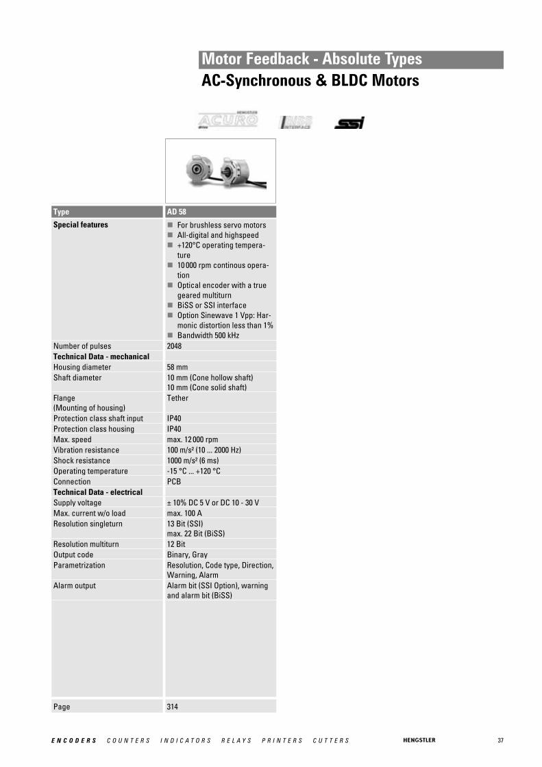
Type AD 58
Special features � For brushless servo motors� All-digital and highspeed� +120°C operating tempera-
ture� 10 000 rpm continous opera-
tion� Optical encoder with a true
geared multiturn� BiSS or SSI interface� Option Sinewave 1 Vpp: Har-
monic distortion less than 1%� Bandwidth 500 kHz
Number of pulses 2048Technical Data - mechanical Housing diameter 58 mmShaft diameter 10 mm (Cone hollow shaft)
10 mm (Cone solid shaft)Flange (Mounting of housing)
Tether
Protection class shaft input IP40Protection class housing IP40Max. speed max. 12 000 rpmVibration resistance 100 m/s² (10 ... 2000 Hz)Shock resistance 1000 m/s² (6 ms)Operating temperature -15 °C ... +120 °CConnection PCBTechnical Data - electrical Supply voltage ± 10% DC 5 V or DC 10 - 30 VMax. current w/o load max. 100 AResolution singleturn 13 Bit (SSI)
max. 22 Bit (BiSS)Resolution multiturn 12 BitOutput code Binary, GrayParametrization Resolution, Code type, Direction,
Warning, AlarmAlarm output Alarm bit (SSI Option), warning
and alarm bit (BiSS)
38 E N C O D E R S C O U N T E R S I N D I C A T O R S R E L A Y S P R I N T E R S C U T T E R S
Motor Feedback - Sine-wave TypesAC-Synchronous & BLDC Motors
Page 317
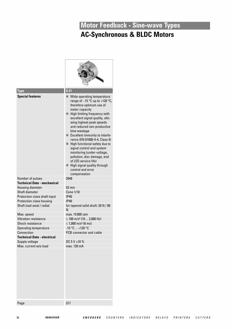
Type S 21
Special features � Wide operating temperaturerange of −15 °C up to +120 °C,therefore optimum use ofmotor capacity
� High limiting frequency withexcellent signal quality, allo-wing highest peak speedsand reduced non-productivetime wastage
� Excellent immunity to interfe-rence (EN 61000-4-4, Class 4)
� High functional safety due tosignal control and systemmonitoring (under-voltage,pollution, disc damage, end of LED service life)
� High signal quality throughcontrol and error compensation
Number of pulses 2048Technical Data - mechanical Housing diameter 53 mmShaft diameter Cone 1/10Protection class shaft input IP40Protection class housing IP40Shaft load axial / radial for tapered solid shaft: 20 N / 90
NMax. speed max. 15 000 rpmVibration resistance ≤ 100 m/s² (10 ... 2,000 Hz)Shock resistance ≤ 1,000 m/s² (6 ms)Operating temperature -15 °C ... +120 °CConnection PCB connector and cableTechnical Data - electrical Supply voltage DC 5 V ±10 % Max. current w/o load max. 120 mA
39E N C O D E R S C O U N T E R S I N D I C A T O R S R E L A Y S P R I N T E R S C U T T E R S
Motor Feedback - Resolvers
Page 320 321 321
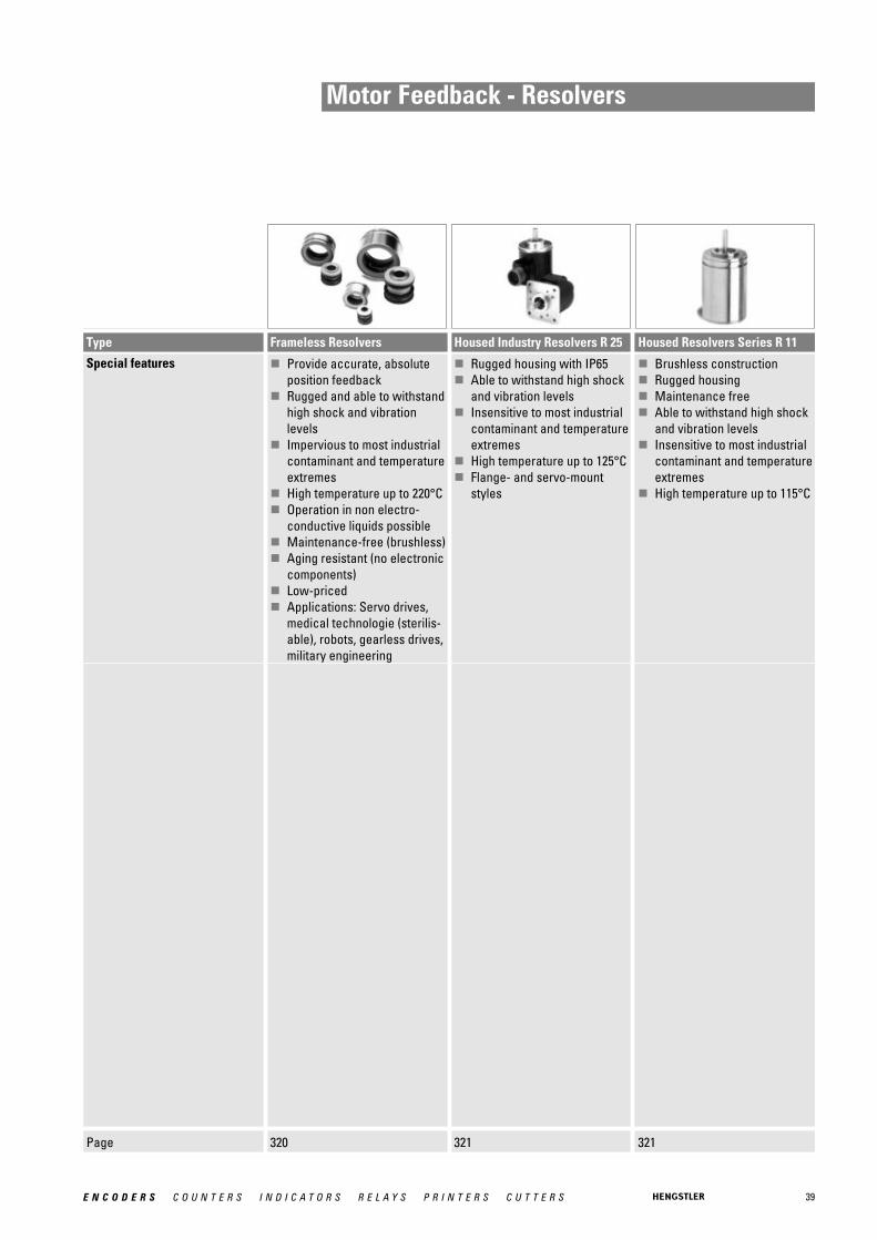
Type Frameless Resolvers Housed Industry Resolvers R 25 Housed Resolvers Series R 11
Special features � Provide accurate, absoluteposition feedback
� Rugged and able to withstandhigh shock and vibrationlevels
� Impervious to most industrialcontaminant and temperatureextremes
� High temperature up to 220°C� Operation in non electro-
conductive liquids possible� Maintenance-free (brushless)� Aging resistant (no electronic
components)� Low-priced� Applications: Servo drives,
medical technologie (sterilis-able), robots, gearless drives,military engineering
� Rugged housing with IP65� Able to withstand high shock
and vibration levels� Insensitive to most industrial
contaminant and temperatureextremes
� High temperature up to 125°C� Flange- and servo-mount
styles
� Brushless construction� Rugged housing� Maintenance free� Able to withstand high shock
and vibration levels� Insensitive to most industrial
contaminant and temperatureextremes
� High temperature up to 115°C

40 E N C O D E R S C O U N T E R S I N D I C A T O R S R E L A Y S P R I N T E R S C U T T E R S
Application Examples for Encoders
Encoder Applications:
■ Packaging industry■ Food industry■ Medical technology■ Elevators■ Conveyor systems■ Robotics■ Cranes■ Positioning control■ Electronics■ Baggage conveyor systems■ Metalworking
■ Motors■ Servo motors■ Vector drives■ Mechanical engineering■ Turning machines■ Stamping machines■ Bending machines■ Welding systems■ Sawing machinesetc.

41E N C O D E R S C O U N T E R S I N D I C A T O R S R E L A Y S P R I N T E R S C U T T E R S
Application Examples with Encoders
42 E N C O D E R S C O U N T E R S I N D I C A T O R S R E L A Y S P R I N T E R S C U T T E R S
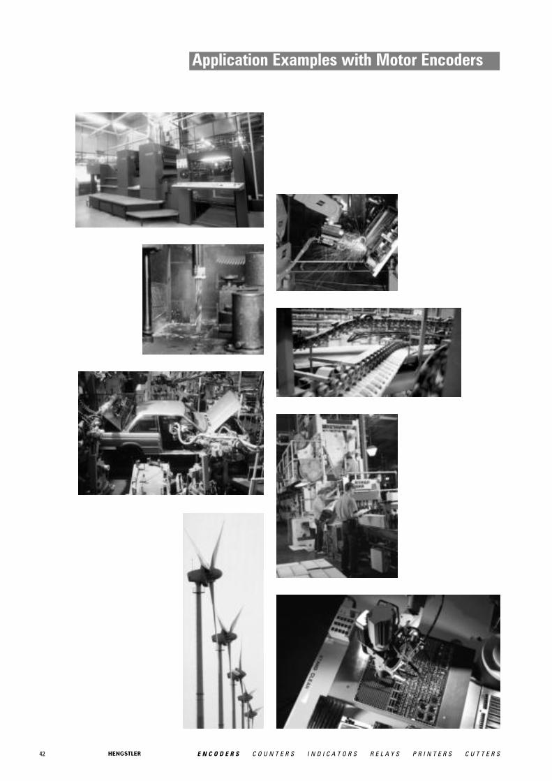
Application Examples with Motor Encoders

43E N C O D E R S C O U N T E R S I N D I C A T O R S R E L A Y S P R I N T E R S C U T T E R S
Heavy Duty Types
Hengstler offers a new series of incremental and absolute encodersin compact size that provide the ruggedness of big magnetic ring kitencoders. Choose from a growing line of Heavy Duty encoders designed to provide reliable operation in harsh duty industrial applications that will not corrode and can withstand temperatureextremes from -40ºC to +100ºC
Hengstler’s Heavy Duty product line offers extreme shock and vibration resistance, special labyrinth sealing options on selectmodels, hazardous environment ATEX certification as well asextreme corrosion and wash down resistant stainless and nickel plated models designed for the special application needs of the foodand beverage industry among others.
■ wind power plants■ commercial solar plants■ oil field exploration
- draw works- rough necks
■ construction machinery■ utility vehicles/ trucks■ steel mills■ paper mills■ saw mills
■ gantry cranes■ marine equipment■ offshore applications■ food & beverage ■ filling plants ■ paper processing■ converting machinery■ material handling■ your individual application
Examples of applications for Heavy Duty encoders:
Heav
y Du
ty
HEAVY DUTYHEAVY DUTHEAVY DUTY
RR
ACURO -XRobustACURO -XRobust

44 E N C O D E R S C O U N T E R S I N D I C A T O R S R E L A Y S P R I N T E R S C U T T E R S
Heavy Duty Types HD 20Incremental
� Single or Dual output� ATEX Certfication available for Intrinsically Safe application� High Resolution Unbreakable Disk� Industrial Duty Connector� NEMA 4X / IP67 Rated� Nickel or Stainless Steel Housing available
NUMBER OF PULSES 0001 / 0024 / 0025 / 0035 / 0040 / 0060 / 0100 / 0120 / 0192 / 0200 / 0240 / 0250 / 0256 / 0300 /0360 / 0500 / 0512 / 0600 / 0625 / 0720 / 1000 / 1024 / 1200 / 1250 / 1440 / 2000 / 2048 / 2500 /2540 / 3600
GENERAL INFORMATION HARSH-DUTY OPTICAL ENCODER
The HD20 Harsh-Duty Optical Encoder is a compact heavy-duty encoder designed toexceed IP66/IP67 and NEMA 6 enclosure requirements. It is also available in stainless steelthat exceeds NEMA 4X and NEMA 6P requirements and is ideal for stringent wash downenvironments, including those where high pressure steam or caustic chemicals are neededto meet regulatory requirements.
The HD20 features max. 440N Axial and Radial Bearings, −40° to +100°C temperature rangeand unique labyrinth double-sealed housing, and optional dual "redundant" outputs and iscovered by a two-year warranty (one year for bearings). NorthStar's traditional quality,reliability and value are built-in to every HD20 encoder.
Also available in this series, is an Intrinsically Safe version certified to ATEX EEx ia IIB T4 whenused with the appropriate IS Barrier. Accessory barriers can be supplied with the encoder.
APPLICATIONS The HD20 Harsh-Duty Optical Encoder is ideal for machine applications with corrosive envi-ronments that demand heavy washdown protection. This compact, special-duty encoder isdesigned to excede IP66/IP67 and NEMA 6 enclosure requirements with a PPR rangethrough 3600. ATEX certification is also available for intrinsically safe applications. • Converting Machinery • Material Handling • Packaging Equipment • Pickling Equipment • Processing Equipment
Industries
Chemical, Food & Beverage, Oil & Gas, Paper, Steel and any other where a precise encoderis needed to operate in harsh environments.
TECHNICAL DATA mechanical
Housing diameter 52.3 mm
Shaft diameter 9.52 mm / 10 mm (Solid shaft)
Flange (Mounting of housing)
Square flange
Protection class shaft input (EN 60529)
NEMA 4X or IP67
Protection class housing (EN 60529)
NEMA 4X or IP67
45E N C O D E R S C O U N T E R S I N D I C A T O R S R E L A Y S P R I N T E R S C U T T E R S
Heavy Duty Types HD 20Incremental
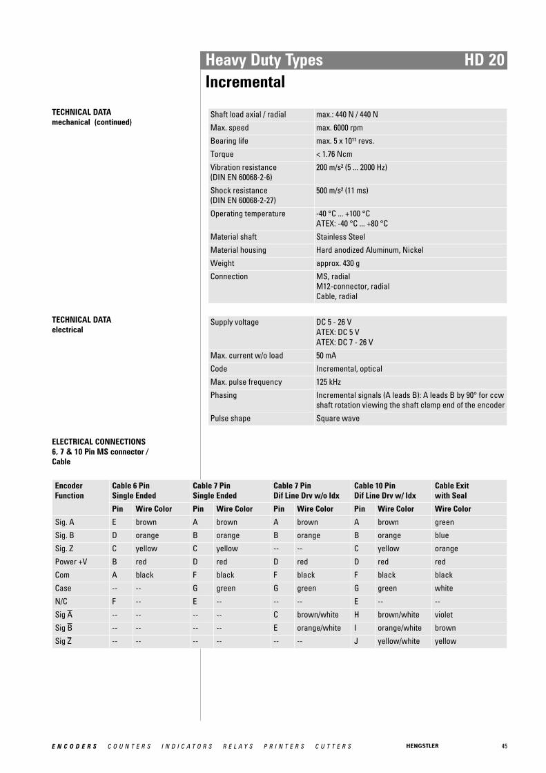
TECHNICAL DATA mechanical (continued)
Shaft load axial / radial max.: 440 N / 440 N
Max. speed max. 6000 rpm
Bearing life max. 5 x 10¹¹ revs.
Torque < 1.76 Ncm
Vibration resistance (DIN EN 60068-2-6)
200 m/s² (5 ... 2000 Hz)
Shock resistance (DIN EN 60068-2-27)
500 m/s² (11 ms)
Operating temperature -40 °C ... +100 °CATEX: -40 °C ... +80 °C
Material shaft Stainless Steel
Material housing Hard anodized Aluminum, Nickel
Weight approx. 430 g
Connection MS, radialM12-connector, radialCable, radial
TECHNICAL DATA electrical
Supply voltage DC 5 - 26 VATEX: DC 5 VATEX: DC 7 - 26 V
Max. current w/o load 50 mA
Code Incremental, optical
Max. pulse frequency 125 kHz
Phasing Incremental signals (A leads B): A leads B by 90° for ccwshaft rotation viewing the shaft clamp end of the encoder
Pulse shape Square wave
ELECTRICAL CONNECTIONS6, 7 & 10 Pin MS connector / Cable
Encoder Function
Cable 6 Pin Single Ended
Cable 7 Pin Single Ended
Cable 7 Pin Dif Line Drv w/o Idx
Cable 10 Pin Dif Line Drv w/ Idx
Cable Exit with Seal
Pin Wire Color Pin Wire Color Pin Wire Color Pin Wire Color Wire Color
Sig. A E brown A brown A brown A brown green
Sig. B D orange B orange B orange B orange blue
Sig. Z C yellow C yellow -- -- C yellow orange
Power +V B red D red D red D red red
Com A black F black F black F black black
Case -- -- G green G green G green white
N/C F -- E -- -- -- E -- --
Sig A -- -- -- -- C brown/white H brown/white violet
Sig B -- -- -- -- E orange/white I orange/white brown
Sig Z -- -- -- -- -- -- J yellow/white yellow

46 E N C O D E R S C O U N T E R S I N D I C A T O R S R E L A Y S P R I N T E R S C U T T E R S
Heavy Duty Types HD 20Incremental
DIMENSIONED DRAWINGS
<1> Standard Housing<2> Dual Redundant Outputs<3> Cable Exit
<4> Flat<5> Thru hole for 8-32<6> Shaft diameter Dimensions in inch [mm]
47E N C O D E R S C O U N T E R S I N D I C A T O R S R E L A Y S P R I N T E R S C U T T E R S
Heavy Duty Types HD 20Incremental
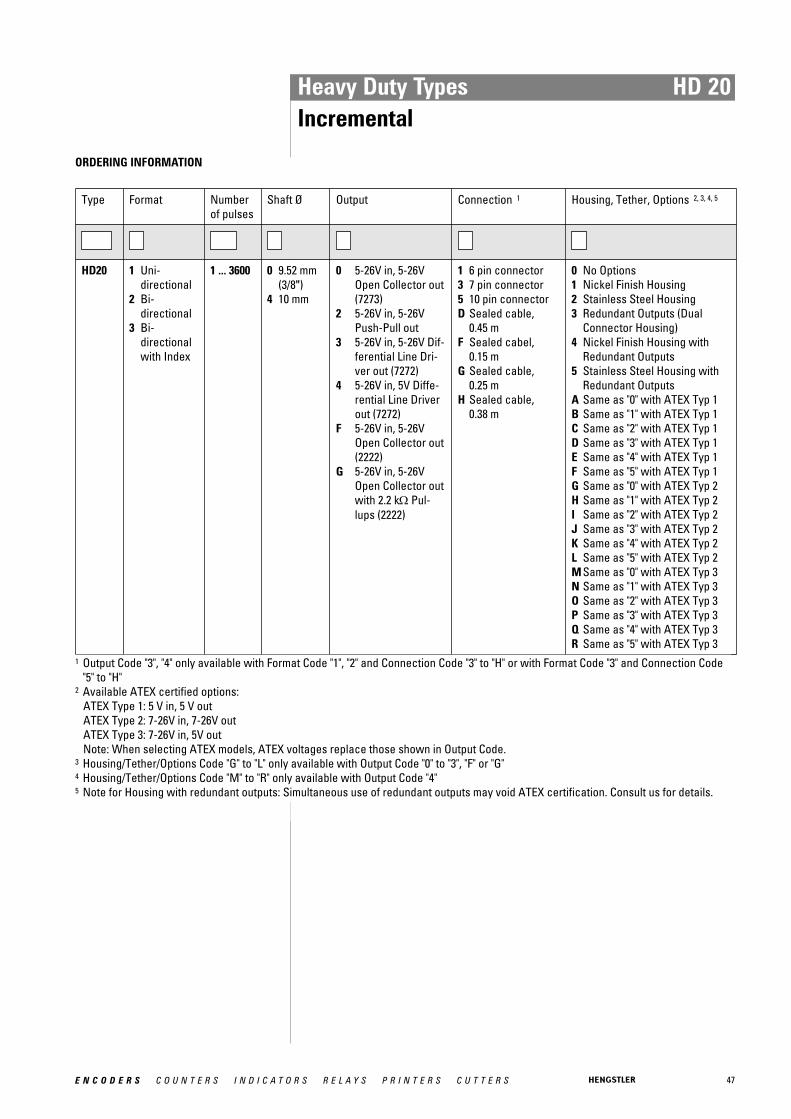
ORDERING INFORMATION
Type Format Numberof pulses
Shaft Ø Output Connection 1 Housing, Tether, Options 2, 3, 4, 5
HD20 1 Uni-directional
2 Bi-directional
3 Bi-directionalwith Index
1 ... 3600 0 9.52 mm(3/8")
4 10 mm
0 5-26V in, 5-26VOpen Collector out(7273)
2 5-26V in, 5-26VPush-Pull out
3 5-26V in, 5-26V Dif-ferential Line Dri-ver out (7272)
4 5-26V in, 5V Diffe-rential Line Driverout (7272)
F 5-26V in, 5-26VOpen Collector out(2222)
G 5-26V in, 5-26VOpen Collector outwith 2.2 kΩ Pul-lups (2222)
1 6 pin connector3 7 pin connector5 10 pin connectorD Sealed cable,
0.45 mF Sealed cabel,
0.15 mG Sealed cable,
0.25 mH Sealed cable,
0.38 m
0 No Options1 Nickel Finish Housing2 Stainless Steel Housing3 Redundant Outputs (Dual
Connector Housing)4 Nickel Finish Housing with
Redundant Outputs5 Stainless Steel Housing with
Redundant OutputsA Same as "0" with ATEX Typ 1B Same as "1" with ATEX Typ 1C Same as "2" with ATEX Typ 1D Same as "3" with ATEX Typ 1E Same as "4" with ATEX Typ 1F Same as "5" with ATEX Typ 1G Same as "0" with ATEX Typ 2H Same as "1" with ATEX Typ 2I Same as "2" with ATEX Typ 2J Same as "3" with ATEX Typ 2K Same as "4" with ATEX Typ 2L Same as "5" with ATEX Typ 2M Same as "0" with ATEX Typ 3N Same as "1" with ATEX Typ 3O Same as "2" with ATEX Typ 3P Same as "3" with ATEX Typ 3Q Same as "4" with ATEX Typ 3R Same as "5" with ATEX Typ 3
1 Output Code "3", "4" only available with Format Code "1", "2" and Connection Code "3" to "H" or with Format Code "3" and Connection Code"5" to "H"
2 Available ATEX certified options: ATEX Type 1: 5 V in, 5 V out ATEX Type 2: 7-26V in, 7-26V out ATEX Type 3: 7-26V in, 5V out Note: When selecting ATEX models, ATEX voltages replace those shown in Output Code.
3 Housing/Tether/Options Code "G" to "L" only available with Output Code "0" to "3", "F" or "G" 4 Housing/Tether/Options Code "M" to "R" only available with Output Code "4"5 Note for Housing with redundant outputs: Simultaneous use of redundant outputs may void ATEX certification. Consult us for details.

48 E N C O D E R S C O U N T E R S I N D I C A T O R S R E L A Y S P R I N T E R S C U T T E R S
Heavy Duty Types HD 25Incremental
� Single or Dual output� Optional high current line driver� ATEX Certfication available for Intrinsically Safe application� High Resolution Unbreakable Disk� Industrial Duty Connector� NEMA 4X / IP67 Rated� Nickel or Stainless Steel Housing available
NUMBER OF PULSES 0001 / 0025 / 0035 / 0040 / 0050 / 0060 / 0100 / 0120 / 0192 / 0200 / 0240 / 0250 / 0256 / 0300 /0360 / 0500 / 0512 / 0600 / 0625 / 0720 / 0900 / 1000 / 1024 / 1200 / 1250 / 1440 / 1524 / 1600 /1800 / 2000 / 2048 / 2500 / 2540 / 3000 / 3048 / 3600 / 4096 / 5000
GENERAL INFORMATION HARSH-DUTY OPTICAL ENCODER
The HD25 Harsh-Duty Optical Encoder is a compact heavy-duty encoder designed toexceed IP66/IP67 and NEMA 6 enclosure requirements. It is also available in stainless steelthat exceeds NEMA 4X and NEMA 6P requirements and is ideal for stringent wash downenvironments, including those where high pressure steam or caustic chemicals are neededto meet regulatory requirements.
The HD25 features max. 440N Axial and Radial Bearings, −40° to +100°C temperature rangeand unique labyrinth double-sealed housing, and optional dual "redundant" outputs and iscovered by a two-year warranty (one year for bearings). NorthStar's traditional quality,reliability and value are built-in to every HD25 encoder.
Also available in this series, is an Intrinsically Safe version certified to ATEX EEx ia IIB T4 whenused with the appropriate IS Barrier. Accessory barriers can be supplied with the encoder.
APPLICATIONS The HD25 Harsh-Duty Optical Encoder is ideal for machine applications with corrosive envi-ronments that demand heavy washdown protection. This compact, special-duty encoder isdesigned to excede IP66/IP67 and NEMA 6 enclosure requirements with a PPR rangethrough 5000. ATEX certification is also available for intrinsically safe applications.
• Converting Machinery • Material Handling • Packaging Equipment • Pickling Equipment • Processing Equipment
Industries
Chemical, Food & Beverage, Oil & Gas, Paper, Steel and any other where a precise encoderis needed to operate in harsh environments.
TECHNICAL DATA mechanical
Housing diameter 67.3 mm
Shaft diameter 3/8" / 10 mm (Solid shaft)
Flange (Mounting of housing)
Square flange
Protection class shaft input (EN 60529)
NEMA 4X or IP67

49E N C O D E R S C O U N T E R S I N D I C A T O R S R E L A Y S P R I N T E R S C U T T E R S
Heavy Duty Types HD 25Incremental
TECHNICAL DATA mechanical (continued)
Protection class housing (EN 60529)
NEMA 4X or IP67
Shaft load axial / radial max.: 440 N / 440 N
Max. speed max. 6000 rpm
Bearing life max. 5 x 10¹¹ revs.
Torque < 1.76 Ncm
Vibration resistance (DIN EN 60068-2-6)
200 m/s² (5 ... 2000 Hz)
Shock resistance (DIN EN 60068-2-27)
500 m/s² (11 msec)
Operating temperature -40 °C ... +100 °CATEX: -40 °C ... +80 °C
Material shaft Stainless Steel
Material housing Hard anodized Aluminum, Nickel, Stainless Steel
Weight approx. 430 g
Connection MS, radialM12-connector, radial
TECHNICAL DATA electrical
Supply voltage DC 5 - 26 VATEX: DC 5 VATEX: DC 7 - 26 V
Max. current w/o load 50 mA
Code Incremental, optical
Max. pulse frequency 125 kHz
Phasing Incremental signals (A leads B): A leads B by 90° for ccwshaft rotation viewing the shaft clamp end of the encoder
Pulse shape Square wave
ELECTRICAL CONNECTIONS6, 7 & 10 Pin MS connector / Cable
Encoder Function
Cable 6 Pin Single Ended
Cable 7 Pin Single Ended
Cable 7 Pin Dif Line Drv w/o Idx
Cable 10 Pin Dif Line Drv w/ Idx
Cable Exit with Seal
Pin Wire Color Pin Wire Color Pin Wire Color Pin Wire Color Wire Color
Sig. A E brown A brown A brown A brown green
Sig. B D orange B orange B orange B orange blue
Sig. Z C yellow C yellow -- -- C yellow orange
Power +V B red D red D red D red red
Com A black F black F black F black black
Case -- -- G green G green G green white
N/C F -- E -- -- -- E -- --
Sig A -- -- -- -- C brown/white H brown/white violet
Sig B -- -- -- -- E orange/white I orange/white brown
Sig Z -- -- -- -- -- -- J yellow/white yellow

50 E N C O D E R S C O U N T E R S I N D I C A T O R S R E L A Y S P R I N T E R S C U T T E R S
Heavy Duty Types HD 25Incremental
DIMENSIONED DRAWINGS
<1> Standard Housing<2> Dual Redundant Outputs<3> Cable Exit<4> Flat<5> Shaft diameter
<6> 10-32 UNF 2B x 0.38" deepon 1.875" bolt circle
Dimensions in inch [mm]

51E N C O D E R S C O U N T E R S I N D I C A T O R S R E L A Y S P R I N T E R S C U T T E R S
Heavy Duty Types HD 25Incremental
ORDERING INFORMATION
Type Format Numberof pulses
Shaft Ø Output Connection 1 Housing, Tether, Options 2, 3, 4, 5
HD25 1 Uni-directional
2 Bi-directional
3 Bi-directionalwith Index
1 ... 5000 0 9.52 mm(3/8")
4 10 mm
0 5-26V in, 5-26VOpen Collector out(7273)
2 5-26V in, 5-26VPush-Pull out
3 5-26V in, 5-26V Dif-ferential Line Dri-ver out (7272)
4 5-26V in, 5V Diffe-rential Line Driverout (7272)
6 5-15V in, 5-15V Dif-ferential Line Dri-ver out (4469)
F 5-26V in, 5-26VOpen Collector out(2222)
G 5-26V in, 5-26VOpen Collector outwith 2.2 kΩ Pul-lups (2222)
1 6 pin connector3 7 pin connector5 10 pin connectorD Sealed cable,
0.45 mF Sealed cabel,
0.15 mG Sealed cable,
0.25 mH Sealed cable,
0.38 m
0 No Options1 Nickel Finish Housing2 Stainless Steel Housing3 Redundant Outputs (Dual
Connector Housing)4 Nickel Finish Housing with
Redundant Outputs5 Stainless Steel Housing with
Redundant OutputsA Same as "0" with ATEX Typ 1B Same as "1" with ATEX Typ 1C Same as "2" with ATEX Typ 1D Same as "3" with ATEX Typ 1E Same as "4" with ATEX Typ 1F Same as "5" with ATEX Typ 1G Same as "0" with ATEX Typ 2H Same as "1" with ATEX Typ 2I Same as "2" with ATEX Typ 2J Same as "3" with ATEX Typ 2K Same as "4" with ATEX Typ 2L Same as "5" with ATEX Typ 2M Same as "0" with ATEX Typ 3N Same as "1" with ATEX Typ 3O Same as "2" with ATEX Typ 3P Same as "3" with ATEX Typ 3Q Same as "4" with ATEX Typ 3R Same as "5" with ATEX Typ 3
1 Output Code "3", "4", "6" only available with Format Code "1", "2" and Connection Code "3" to "H" or with Format Code "3" and ConnectionCode "5" to "H"
2 Available ATEX certified options:ATEX Type 1: 5 V in, 5 V outATEX Type 2: 7-26V in, 7-26V outATEX Type 3: 7-26V in, 5V outNote: When selecting ATEX models, ATEX voltages replace those shown in Output Code.
3 Housing/Tether/Options Code "G" to "L" only available with Output Code "0" to "3", "F" or "G"4 Housing/Tether/Options Code "M" to "R" only available with Output Code "4"5 Note for Housing with redundant outputs: Simultaneous use of redundant outputs may void ATEX certification. Consult us for details.

52 E N C O D E R S C O U N T E R S I N D I C A T O R S R E L A Y S P R I N T E R S C U T T E R S
Heavy Duty Types HSD 25Incremental
� Single or Dual output� ATEX Certfication available for Intrinsically Safe application� High Resolution Unbreakable Disk� Industrial Duty Connector� NEMA 4X, 6 / IP66, 67 Rated� Nickel or Stainless Steel Housing available
NUMBER OF PULSES 0001 / 0024 / 0035 / 0040 / 0050 / 0060 / 0100 / 0120 / 0192 / 0200 / 0240 / 0250 / 0256 / 0300 /0360 / 0500 / 0512 / 0600 / 0625 / 0720 / 1000 / 1024 / 1200 / 1250 / 1440 / 2000 / 2048 / 2500 /2540 / 3000 / 3600
GENERAL INFORMATION HARSH-DUTY OPTICAL HUB SHAFT ENCODER
NorthStar's HSD25 Harsh-Duty Optical Hub Shaft Encoder accepts up to 0.75" diametershafts and operates reliably from −40 to +100°C. The hard anodized finish encoder exceedsIP66/IP67 and NEMA 6 enclosure requirements.
This robust encoder is also available in Stainless Steel to meet NEMA 4x and 6P requirementsand its sealed housing allows the Encoder to be operated when regulatory washdown andhigh pressure steam or caustic chemicals are required. Utilization of an advanced OptoASIC with innovative packaging techniques enables the encoder to operate in high shock andvibration environments.
The HSD25 is also available in an Intrinsically Safe version certified to ATEX EEx ia IIB T4 whenused with the appropriate IS barrier.
APPLICATIONS The HSD25 Harsh-Duty Optical Encoder features simple installation on motor or machinehub shafts. It is often mounted on the back of motors where encoder feedback is needed inharsh environment applications. Available housing options make it ideal use in corrosiveenvironments that demand heavy washdown protection. ATEX certification is also availablefor intrinsically safe applications. • Converting Machinery • Material Handling • Packaging Equipment • Oil Field Exploration • Processing Equipment
INDUSTRIES
Chemical, Food & Beverage, Oil & Gas, Paper, Steel and any other where a precise encoderis needed to operate in harsh environments.
TECHNICAL DATA mechanical
Housing diameter 58.93 mm
Shaft diameter 3/8" / 10 mm / 12.7 mm / 5/8" / 3/4" (Hubshaft)
Flange (Mounting of housing)
Tether
Mounting of shaft Front clamping ring
Protection class shaft input (EN 60529)
NEMA 4X or NEMA 6IP66 or IP67

53E N C O D E R S C O U N T E R S I N D I C A T O R S R E L A Y S P R I N T E R S C U T T E R S
Heavy Duty Types HSD 25Incremental
TECHNICAL DATA mechanical (continued)
Protection class housing (EN 60529)
NEMA 4X or NEMA 6IP66 or IP67
Bearing life max. 5 x 10¹¹ revs.
Torque < 1.76 Ncm
Vibration resistance (DIN EN 60068-2-6)
200 m/s² (5 ... 2000 Hz)
Shock resistance (DIN EN 60068-2-27)
500 m/s² (11 sec)
Operating temperature -40 °C ... +100 °CATEX: -40 °C ... +80 °C
Material shaft Stainless Steel
Material housing Hard anodized Aluminum, Nickel, Stainless Steel
Weight approx. 600 g
Connection MS, radialM12-connector, radialCable, radial
TECHNICAL DATA electrical
Supply voltage DC 5 - 26 VATEX: DC 5 VATEX: DC 7 - 26 V
Max. current w/o load 50 mA
Code Incremental, optical
Max. pulse frequency 125 kHz
Phasing Incremental signals (A leads B): A leads B by 90° for ccwshaft rotation viewing the shaft clamp end of the encoder
Pulse shape Square wave
ELECTRICAL CONNECTIONS6, 7 & 10 Pin MS connector / Cable
Encoder Function
Cable 6 Pin Single Ended
Cable 7 Pin Single Ended
Cable 7 Pin Dif Line Drv w/o Idx
Cable 10 Pin Dif Line Drv w/ Idx
Cable 12 Pin CCW
Cable Exit with Seal
Pin Wire Color Pin Wire Color Pin Wire Color Pin Wire Color Pin Wire Color Wire Color
Sig. A E brown A brown A brown A brown 5 brown green
Sig. B D orange B orange B orange B orange 8 orange blue
Sig. Z C yellow C yellow -- -- C yellow 3 yellow orange
Power +V B red D red D red D red 12 red red
Com A black F black F black F black 10 black black
Case -- -- G green G green G green 9 -- white
N/C F -- E -- -- -- E -- 7 -- --
Sig. A -- -- -- -- C brown/white H brown/white 6 brown/white violet
Sig. B -- -- -- -- E orange/white I orange/white 1 orange/white brown
Sig. Z -- -- -- -- -- -- J yellow/white 4 yellow/white yellow
0 Volt Sense
-- -- -- -- -- -- -- -- 2 green --
5 Volt Sense
-- -- -- -- -- -- -- -- 11 black/white --

54 E N C O D E R S C O U N T E R S I N D I C A T O R S R E L A Y S P R I N T E R S C U T T E R S
Heavy Duty Types HSD 25Incremental
ELECTRICAL CONNECTIONS5 & 8 Pin M12 Accessory Cable
Encoder Function
Cable 5 Pin Single Ended
Cable 8 Pin Single Ended
Cable 8 Pin Differential
Pin Wire Color
Pin Wire Color
Pin Wire Color
Sig. A 4 black 1 brown 1 brown
Sig. B 2 white 4 orange 4 orange
Sig. Z 5 grey 6 yellow 6 yellow
Power +V 1 brown 2 red 2 red
Com 3 blue 7 black 7 black
Sig. A 3 brown/white
Sig. B 5 orange/white
Sig. Z 8 yellow/white
DIMENSIONED DRAWINGS
<1> Standard Housing<2> 8-32 UNC x .28 deep on 2.000 bolt circel 4 places 90° apart<3> Bore diameter<4> Hub shaft cavity maximum depth<5> Dual Redundant Outputs<6> Cable Exit
<7> 4-40 x .25 deep 4 places - 90° apart<8> 4-40 x .25 deep 90° apart<9> Slotted Tether� Single Point Tether� Ø 0.172 [43.7] ON Ø 2.00 [50.8] B.C.
Dimensions in inch [mm]

55E N C O D E R S C O U N T E R S I N D I C A T O R S R E L A Y S P R I N T E R S C U T T E R S
Heavy Duty Types HSD 25Incremental
ORDERING INFORMATION
Type Numberof pul-ses
Shaft Ø Format 2 4 Output Connection Safety 1 3 Housing, Tether, Options
HSD25 1 ... 3600 4 9.52 mm(3/8")
5 10 mm7 12.7 mm
(1/2")8 5/8"C 3/4"
0 single ended,undirectional(A)
1 single ended,bidirectional(AB)
2 single ended,bidirectionalwith index(ABZ)
3 differential,bidirectional (A¬A B¬B)
4 differential,bidirectionalwith index (A¬A B¬BZ¬Z)
5 Dual isolateddifferential,bidirectionalw/index (A¬AB¬B Z¬Z)
0 5-26V in, 5-26V OpenCollector out(7273)
2 5-26V in, 5-26V Push-Pull out
3 5-26V in, 5-26V Differen-tial Line Dri-ver out (7272)
4 5-26V in, 5VDifferentialLine Driverout (7272)
F 5-26V in, 5-26V OpenCollector out(2222)
G 5-26V in, 5-26V OpenCollector outwith 2.2 kΩPullups(2222)
0 6 pin connector
1 7 pin connector
2 10 pin connector
3 12 pin connector
5 6 pin connec-tor plus matingconnector
6 7 pin connec-tor plus matingconnector
7 10 pin connec-tor plus matingconnector
8 12 pin connec-tor plus matingconnector
A Cable 0,5 mB Cable 1 mC Cable 2 mD Cable 3mF 0.3 m cable
with 10 pinconnector plusmatingconnector
G Cable, 0.3 mH M12 connec-
tor, 5 poleJ M12 connec-
tor, 8 pole
0 NoATEX
1 ATEXType 1Option
2 ATEXType 2Option
3 ATEXType 3Option
0 Cast Aluminum Housing,Slotted Tether
1 Nickel Housing, slottedtether
2 Stainless Housing, slottedtether
3 Redundant Outputs (DualConnector Housing), slot-ted tether
4 Nickel Housing, Redun-dant Outputs, slottedtether
5 Stainless Housing,Redundant Outputs, slot-ted-tether
C Cast Aluminum Housing,Single-Point Tether Inclu-ded (NEMA 4.5" C-face)
D Nickel Housing, single-point tether
E Stainless Housing, single-point tether
F Redundant Outputs (DualConnector Housing),single-point tether
G Nickel Housing, Redun-dant Outputs, single-pointtether
H Stainless Housing,Redundant Outputs,single-point tether
6 Same as "0" but no tether7 Same as "1" but no tether8 Same as "2" but no tether9 Same as "3" but no tetherA Same as "4" but no tetherB Same as "5" but no tether
1 ATEX Type 1: 5 V in, 5 V outATEX Type 2: 7-26V in, 7-26V outATEX Type 3: 7-26V in, 5V out
2 Format Code "3" only available with Output Code "3" or "4" resp. Housing/ Tether Code "0", "1", "2" or "6", "7", "8"3 Safety Code "2" only available with Output Code "4"4 Format Code "4" and Code "5" only available with Output Code "3" or "4" resp. Connection Code "A" to "G" and Housing/ Tether Code "0", "1",
"2" or "6", "7", "8"

56 E N C O D E R S C O U N T E R S I N D I C A T O R S R E L A Y S P R I N T E R S C U T T E R S
Heavy Duty Types HSD 35Incremental
� Hollow Shaft design eliminates mounting bracket, flexible shaft coupling, and installa-tion labor
� Bore is electrically and thermally insulated� Single or Dual output - Optional high current line driver� Choice of Stamped Metal or Swivel Rod Tether� High Resolution Unbreakable Disk� Industrial Duty Latching Connector� NEMA 4 / IP65 Rated
NUMBER OF PULSES 0001 / 0002 / 0003 / 0005 / 0006 / 0007 / 0010 / 0012 / 0025 / 0050 / 0060 / 0064 / 0100 / 0120 /0128 / 0180 / 0200 / 0240 / 0250 / 0300 / 0360 / 0400 / 0500 / 0512 / 0600 / 0720 / 0800 / 0900 /1000 / 1024 / 1200 / 1270 / 1500 / 1800 / 2000 / 2048 / 2400 / 2500
GENERAL INFORMATION HEAVY DUTY SEALED HOLLOWSHAFT ENCODER
The NorthStar brand Series HSD35 Sealed Hollowshaft encoder is designed for easy instal-lation on motor or machine shafts. Its hollowshaft design eliminates the need for a flexibleshaft coupling, mounting bracket, flower pot, or flange adapter. This not only reduces theinstallation depth, but also lowers total cost.
The Series HSD35 Sealed Hollowshaft is equipped with an unbreakable disk that resistscontamination and meets the demands of the most severe shock and vibration generatingprocesses. Its floating shaft mount and spring tether eliminate bearing loads and flexibleshaft couplings to eliminate wear and maintenance.
Series HSD35 has complete electrical protection from overvoltage, reverse voltage, andoutput short circuits. In addition, the Series HSD35 is not only electrically & thermally isola-ted, but also environmentally sealed with shaft seals at both ends.
APPLICATIONS The HSD35 sealed hollow shaft encoder is ideal for motor and machine applications at reso-lutions to 2500 PPR. Choice of stamped metal or swivel rod tether provide flexible mountingfor a wide varity of installations • Vector Motor and Drive Feedback • Converting Machinery • Packaging Equipment • Paper Processing
INDUSTRIES
Manufacturing, Assembly, Material Handling and any other where a precise, reliable feed-back signal is required.
TECHNICAL DATA mechanical
Housing diameter 90.2 mm
Shaft diameter 6 mm / 8 mm / 10 mm / 12 mm / 15 mm / 25 mm / 28 mm /31.75 mm (Through hollow shaft)
Flange (Mounting of housing)
Tether, Swivel rod
Mounting of shaft Front clamping ring
Protection class shaft input (EN 60529)
IP65 or NEMA 4

57E N C O D E R S C O U N T E R S I N D I C A T O R S R E L A Y S P R I N T E R S C U T T E R S
Heavy Duty Types HSD 35Incremental
TECHNICAL DATA mechanical (continued)
Protection class housing (EN 60529)
IP65 or NEMA 4
Axial endplay of mounting shaft (hubshaft)
± 1.27 mm
Radial runout of mating shaft (hubshaft)
± 0.63 mm
Max. speed max. 3600 rpm
Bearing life 80 000 hours at 3600 rpm; 128 000 hours at 1800 rpm
Torque 3.53 Ncm (max.)
Vibration resistance (DIN EN 60068-2-6)
200 m/s² (5 ... 2000 Hz)
Shock resistance (DIN EN 60068-2-27)
500 m/s² (11 ms)
Operating temperature -40 °C ... +70 °COption: 0 °C ... +100 °C
Storage temperature -40 °C ... +90 °C
Weight max. 870 g
Connection 10 pin connector
TECHNICAL DATA electrical
Supply voltage DC 4,5 - 26 V
Max. current w/o load 100 mA
Code Incremental, optical
Max. pulse frequency 100 kHz
Phasing Incremental signals (A leads B): A leads B by 90° for ccwshaft rotation viewing the shaft clamp end of the encoder
Pulse shape Square wave

58 E N C O D E R S C O U N T E R S I N D I C A T O R S R E L A Y S P R I N T E R S C U T T E R S
Heavy Duty Types HSD 35Incremental
DIMENSIONED DRAWINGS
<1> Single Output Models<2> Dual Output Models<3> Tether Type & Fixing 4, 5, 6, 7, F, G, H, J (see ordering information)
<4> Cover option<5> 12.19 mm thru holes on 149 mm bolt circle (6 places)

59E N C O D E R S C O U N T E R S I N D I C A T O R S R E L A Y S P R I N T E R S C U T T E R S
Heavy Duty Types HSD 35Incremental
ORDERING INFORMATION
Type Numberof pulses
Shaft Ø Tether Type & Fixing 1, 2 Format 3 Output Seal Housing,Tether,Options
HSD35 1 ... 2500 0 6 mm1 1/4"2 5/16"3 8 mm4 9.52 mm
(3/8")5 10 mm6 12 mm7 12.7 mm
(1/2")8 5/8"9 15 mmA 16 mmB 19 mmC 3/4"D 20 mmE 7/8"F 24 mmG 1"H 1-1/8"J 14 mmK 18 mmM 25 mmN 28 mmP 1-1/4"
A Standard Tether C 180C TetherE 180C Tether with protective
guardB 56C TetherD 56C Tether with protective
guard0 None - customer suppliedH Same as 'A' w/ dual cover
kitF Same as 'A', w/ cover kitJ Same as 'B' w/ dual cover
kitG Same as 'B', w/ cover kit
0 single ended,undirectional(A)
1 single ended,bidirectional(AB)
2 single ended,bidirectionalwith index(ABZ)
3 differential,bidirectional (A¬A B¬B)
4 differential,bidirectionalwith index ( A¬A B¬BZ¬Z)
5 Dual isolateddifferential,bidirectionalw/index (A¬AB¬B Z¬Z)
0 5 - 26 V in, 5 -26 V OpenCollector out
0 5-26V in, 5-26V OpenCollector out(7273)
2 5 - 26 V in, 5 -26 V Push pullout
1 5-26V in, 5-26V opencollector outwith 2.2kΩpullups
2 5-26V in, 5-26V Push-Pullout
3 5 - 26 V in, 5 -26 V Differen-tial Line Driverout
4 5-26V in, 5VDifferentialLine Driverout
A same as '3'but up to+100°C
B same as '4'but up to+100°C
1 RuggedShaftSeals
0 Stan-dardShaftSeals
BlankNone
D LEDOutputIndica-tor
1 Tether Type & Fixing Code "F" or Code"G" only available with Format Code "0" to "4"2 Housing Tether & Fixing Code "H" or Code"J" only available with Format Code "5"3 Format Code "3" to Code "5" only available with Output Code "3" to Code "6" and Code "A" resp. "B"

60 E N C O D E R S C O U N T E R S I N D I C A T O R S R E L A Y S P R I N T E R S C U T T E R S
Heavy Duty Types HSD 37Incremental
� Single or Dual Output� Double-Sealed Housing� ATEX Certification for Intrinsically Safe Applications� High Resolution Unbreakable Disk� Electrically and Thermally Isolated� Industrial Duty Connector� NEMA 4X, 6 / IP66, 67 Rated� Rugged Cast-Aluminum Housing� Stainless Steel Housing Available
NUMBER OF PULSES 0015 / 0032 / 0100 / 0200 / 0240 / 0250 / 0500 / 0512 / 0600 / 1000 / 1024 / 1200 / 2000 / 2048 /2500 / 4000 / 5000
GENERAL INFORMATION EXTREME HEAVY DUTY HOLLOWSHAFT ENCODER
NorthStar's HSD37 Extreme Duty Industrial Hollowshaft Encoder accepts up to 1" diametershafts and operates reliably from −40 to +100°C. Its Hard Anodized finish enclosure exceedsIP66/IP67 and NEMA 6 enclosure requirements.
This robust encoder features a double-sealed housing that allows application where regu-latory washdown or caustic chemicals are present. Utilization of an advanced Opto ASICwith innovative packaging techniques enables the encoder to operate in high shock andvibration environments.
It is also available in an Intrinsically Safe version, certified to ATEX EEx ia IIB T4, when usedwith the appropriate IS Barrier.
APPLICATIONS The HSD37 extreme duty encoder features simple installation on motor or machine shafts. Itis often mounted on the back of motors where encoder feedback is needed in harsh envi-ronment applications. It is ideal for use in environments that demand heavy washdown pro-tection. • Converting Machinery • Material Handling • Packaging Equipment • Processing Equipment
Industries
Chemical, Food & Beverage, Oil & Gas, Paper, Steel and any other where a precise encoderis needed to operate in harsh environments.
TECHNICAL DATA mechanical
Housing diameter 95.25 mm
Shaft diameter 12 mm / 1/2" / 15 mm / 5/8" / 16 mm / 3/4" / 0.875" (Throughhollow shaft)
Flange (Mounting of housing)
Tether
Mounting of shaft Front clamping ring
Protection class shaft input (EN 60529)
NEMA 4X or NEMA 6IP66 or IP67
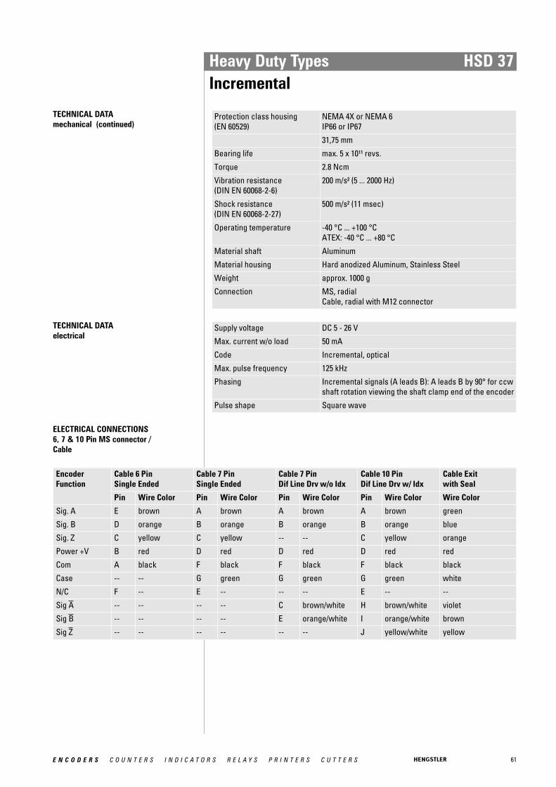
61E N C O D E R S C O U N T E R S I N D I C A T O R S R E L A Y S P R I N T E R S C U T T E R S
Heavy Duty Types HSD 37Incremental
TECHNICAL DATA mechanical (continued)
Protection class housing (EN 60529)
NEMA 4X or NEMA 6IP66 or IP67
31,75 mm
Bearing life max. 5 x 10¹¹ revs.
Torque 2.8 Ncm
Vibration resistance (DIN EN 60068-2-6)
200 m/s² (5 ... 2000 Hz)
Shock resistance (DIN EN 60068-2-27)
500 m/s² (11 msec)
Operating temperature -40 °C ... +100 °CATEX: -40 °C ... +80 °C
Material shaft Aluminum
Material housing Hard anodized Aluminum, Stainless Steel
Weight approx. 1000 g
Connection MS, radialCable, radial with M12 connector
TECHNICAL DATA electrical
Supply voltage DC 5 - 26 V
Max. current w/o load 50 mA
Code Incremental, optical
Max. pulse frequency 125 kHz
Phasing Incremental signals (A leads B): A leads B by 90° for ccwshaft rotation viewing the shaft clamp end of the encoder
Pulse shape Square wave
ELECTRICAL CONNECTIONS6, 7 & 10 Pin MS connector / Cable
Encoder Function
Cable 6 Pin Single Ended
Cable 7 Pin Single Ended
Cable 7 Pin Dif Line Drv w/o Idx
Cable 10 Pin Dif Line Drv w/ Idx
Cable Exit with Seal
Pin Wire Color Pin Wire Color Pin Wire Color Pin Wire Color Wire Color
Sig. A E brown A brown A brown A brown green
Sig. B D orange B orange B orange B orange blue
Sig. Z C yellow C yellow -- -- C yellow orange
Power +V B red D red D red D red red
Com A black F black F black F black black
Case -- -- G green G green G green white
N/C F -- E -- -- -- E -- --
Sig A -- -- -- -- C brown/white H brown/white violet
Sig B -- -- -- -- E orange/white I orange/white brown
Sig Z -- -- -- -- -- -- J yellow/white yellow

62 E N C O D E R S C O U N T E R S I N D I C A T O R S R E L A Y S P R I N T E R S C U T T E R S
Heavy Duty Types HSD 37Incremental
ELECTRICAL CONNECTIONS5 & 8 Pin M12 Accessory Cable
Encoder Function
Cable 5 Pin Single Ended
Cable 8 Pin Single Ended
Cable 8 Pin Differential
Pin Wire Color
Pin Wire Color
Pin Wire Color
Sig. A 4 black 1 brown 1 brown
Sig. B 2 white 4 orange 4 orange
Sig. Z 5 grey 6 yellow 6 yellow
Power +V 1 brown 2 red 2 red
Com 3 blue 7 black 7 black
Sig. A 3 brown/white
Sig. B 5 orange/white
Sig. Z 8 yellow/white
DIMENSIONED DRAWINGS
<1> 10-32 UNF x .38 deep on a Ø 3.000 bolt circle<2> 10-32 clamp screw<3> on 3.00 [76.20] bolt circle<4> 10-32 UNF x .38 deep on a Ø 3.000 bolt circle<5> Redundant Version
<6> Pigtail with MS Connector (K Option)<7> Single Point Tether<8> Slotted Tether
Dimensions in inch [mm]
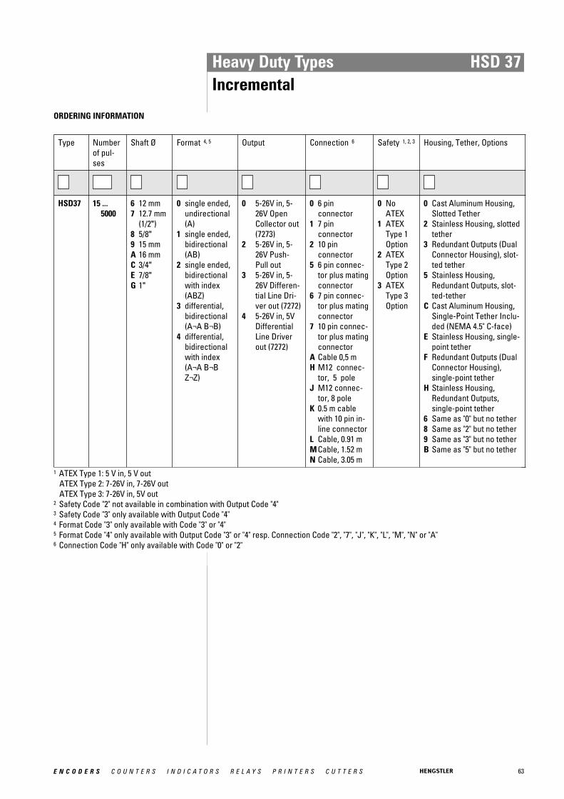
63E N C O D E R S C O U N T E R S I N D I C A T O R S R E L A Y S P R I N T E R S C U T T E R S
Heavy Duty Types HSD 37Incremental
ORDERING INFORMATION
Type Numberof pul-ses
Shaft Ø Format 4, 5 Output Connection 6 Safety 1, 2, 3 Housing, Tether, Options
HSD37 15 ...5000
6 12 mm7 12.7 mm
(1/2")8 5/8"9 15 mmA 16 mmC 3/4"E 7/8"G 1"
0 single ended,undirectional(A)
1 single ended,bidirectional(AB)
2 single ended,bidirectionalwith index(ABZ)
3 differential,bidirectional (A¬A B¬B)
4 differential,bidirectionalwith index (A¬A B¬BZ¬Z)
0 5-26V in, 5-26V OpenCollector out(7273)
2 5-26V in, 5-26V Push-Pull out
3 5-26V in, 5-26V Differen-tial Line Dri-ver out (7272)
4 5-26V in, 5VDifferentialLine Driverout (7272)
0 6 pin connector
1 7 pin connector
2 10 pin connector
5 6 pin connec-tor plus matingconnector
6 7 pin connec-tor plus matingconnector
7 10 pin connec-tor plus matingconnector
A Cable 0,5 mH M12 connec-
tor, 5 poleJ M12 connec-
tor, 8 poleK 0.5 m cable
with 10 pin in-line connector
L Cable, 0.91 mM Cable, 1.52 mN Cable, 3.05 m
0 NoATEX
1 ATEXType 1Option
2 ATEXType 2Option
3 ATEXType 3Option
0 Cast Aluminum Housing,Slotted Tether
2 Stainless Housing, slottedtether
3 Redundant Outputs (DualConnector Housing), slot-ted tether
5 Stainless Housing,Redundant Outputs, slot-ted-tether
C Cast Aluminum Housing,Single-Point Tether Inclu-ded (NEMA 4.5" C-face)
E Stainless Housing, single-point tether
F Redundant Outputs (DualConnector Housing),single-point tether
H Stainless Housing,Redundant Outputs,single-point tether
6 Same as "0" but no tether8 Same as "2" but no tether9 Same as "3" but no tetherB Same as "5" but no tether
1 ATEX Type 1: 5 V in, 5 V outATEX Type 2: 7-26V in, 7-26V outATEX Type 3: 7-26V in, 5V out
2 Safety Code "2" not available in combination with Output Code "4"3 Safety Code "3" only available with Output Code "4"4 Format Code "3" only available with Code "3" or "4"5 Format Code "4" only available with Output Code "3" or "4" resp. Connection Code "2", "7", "J", "K", "L", "M", "N" or "A"6 Connection Code "H" only available with Code "0" or "2"
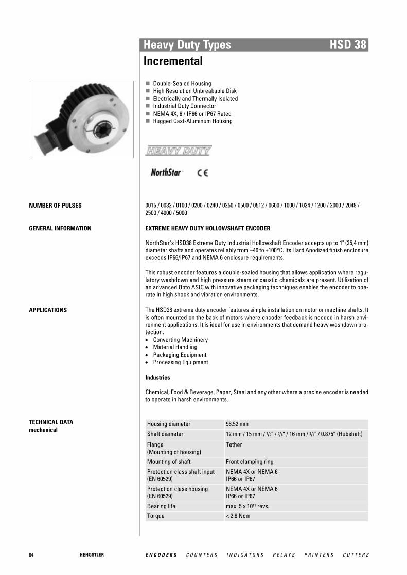
64 E N C O D E R S C O U N T E R S I N D I C A T O R S R E L A Y S P R I N T E R S C U T T E R S
Heavy Duty Types HSD 38Incremental
� Double-Sealed Housing� High Resolution Unbreakable Disk� Electrically and Thermally Isolated� Industrial Duty Connector� NEMA 4X, 6 / IP66 or IP67 Rated� Rugged Cast-Aluminum Housing
NUMBER OF PULSES 0015 / 0032 / 0100 / 0200 / 0240 / 0250 / 0500 / 0512 / 0600 / 1000 / 1024 / 1200 / 2000 / 2048 /2500 / 4000 / 5000
GENERAL INFORMATION EXTREME HEAVY DUTY HOLLOWSHAFT ENCODER
NorthStar's HSD38 Extreme Duty Industrial Hollowshaft Encoder accepts up to 1" (25,4 mm)diameter shafts and operates reliably from −40 to +100°C. Its Hard Anodized finish enclosureexceeds IP66/IP67 and NEMA 6 enclosure requirements.
This robust encoder features a double-sealed housing that allows application where regu-latory washdown and high pressure steam or caustic chemicals are present. Utilization ofan advanced Opto ASIC with innovative packaging techniques enables the encoder to ope-rate in high shock and vibration environments.
APPLICATIONS The HSD38 extreme duty encoder features simple installation on motor or machine shafts. Itis often mounted on the back of motors where encoder feedback is needed in harsh envi-ronment applications. It is ideal for use in environments that demand heavy washdown pro-tection. • Converting Machinery • Material Handling • Packaging Equipment • Processing Equipment
Industries
Chemical, Food & Beverage, Paper, Steel and any other where a precise encoder is neededto operate in harsh environments.
TECHNICAL DATA mechanical
Housing diameter 96.52 mm
Shaft diameter 12 mm / 15 mm / 1/2" / 5/8" / 16 mm / 3/4" / 0.875" (Hubshaft)
Flange (Mounting of housing)
Tether
Mounting of shaft Front clamping ring
Protection class shaft input (EN 60529)
NEMA 4X or NEMA 6IP66 or IP67
Protection class housing (EN 60529)
NEMA 4X or NEMA 6IP66 or IP67
Bearing life max. 5 x 10¹¹ revs.
Torque < 2.8 Ncm

65E N C O D E R S C O U N T E R S I N D I C A T O R S R E L A Y S P R I N T E R S C U T T E R S
Heavy Duty Types HSD 38Incremental
TECHNICAL DATA mechanical (continued)
Vibration resistance (DIN EN 60068-2-6)
200 m/s² (5 ... 2000 Hz)
Shock resistance (DIN EN 60068-2-27)
500 m/s² (11 msec)
Operating temperature -40 °C ... +100 °C
Storage temperature -40 °C ... +100 °C
Material shaft Aluminum
Material housing Hard anodized Aluminum
Weight approx. 800 g
Connection MS, radialCable, radial with M12 connector
TECHNICAL DATA electrical
Supply voltage DC 5 - 26 V
Max. current w/o load 50 mA
Code Incremental, optical
Max. pulse frequency 125 kHz
Phasing Incremental signals (A leads B): A leads B by 90° for ccwshaft rotation viewing the shaft clamp end of the encoder
Pulse shape Square wave
ELECTRICAL CONNECTIONS6, 7 & 10 Pin MS connector / Cable
Encoder Function
Cable 6 Pin Single Ended
Cable 7 Pin Single Ended
Cable 7 Pin Dif Line Drv w/o Idx
Cable 10 Pin Dif Line Drv w/ Idx
Cable Exit with Seal
Pin Wire Color Pin Wire Color Pin Wire Color Pin Wire Color Wire Color
Sig. A E brown A brown A brown A brown green
Sig. B D orange B orange B orange B orange blue
Sig. Z C yellow C yellow -- -- C yellow orange
Power +V B red D red D red D red red
Com A black F black F black F black black
Case -- -- G green G green G green white
N/C F -- E -- -- -- E -- --
Sig A -- -- -- -- C brown/white H brown/white violet
Sig B -- -- -- -- E orange/white I orange/white brown
Sig Z -- -- -- -- -- -- J yellow/white yellow
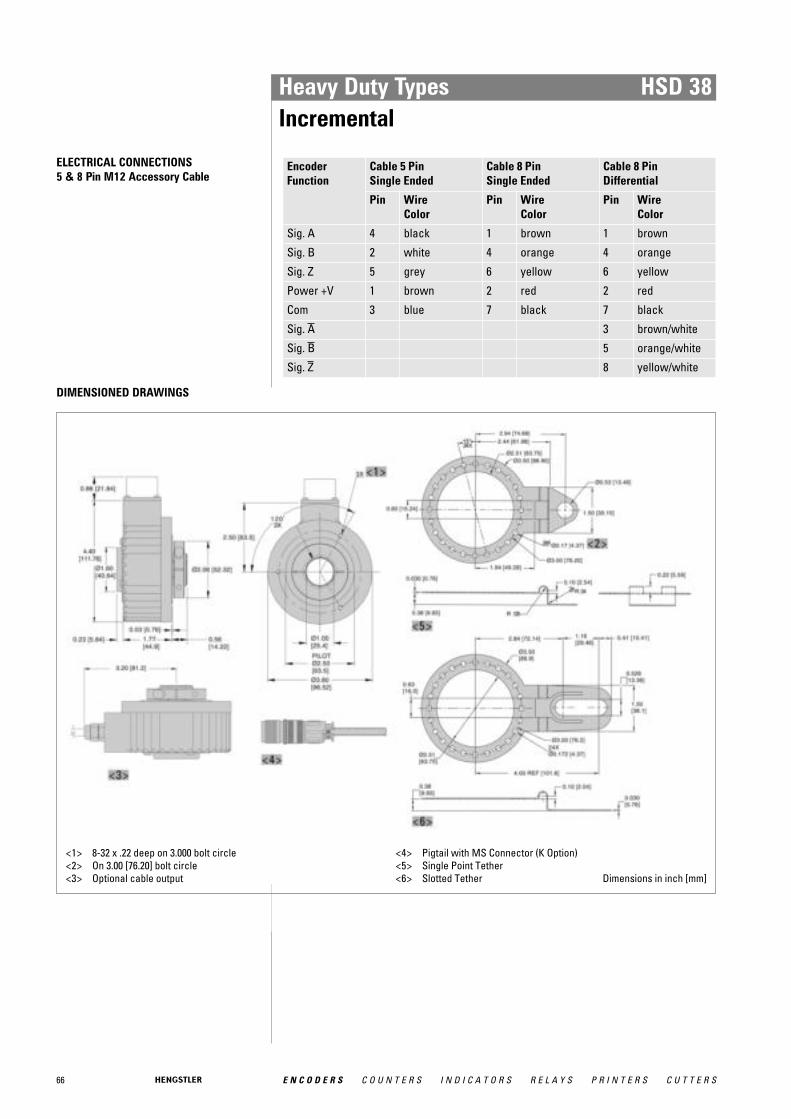
66 E N C O D E R S C O U N T E R S I N D I C A T O R S R E L A Y S P R I N T E R S C U T T E R S
Heavy Duty Types HSD 38Incremental
ELECTRICAL CONNECTIONS5 & 8 Pin M12 Accessory Cable
Encoder Function
Cable 5 Pin Single Ended
Cable 8 Pin Single Ended
Cable 8 Pin Differential
Pin Wire Color
Pin Wire Color
Pin Wire Color
Sig. A 4 black 1 brown 1 brown
Sig. B 2 white 4 orange 4 orange
Sig. Z 5 grey 6 yellow 6 yellow
Power +V 1 brown 2 red 2 red
Com 3 blue 7 black 7 black
Sig. A 3 brown/white
Sig. B 5 orange/white
Sig. Z 8 yellow/white
DIMENSIONED DRAWINGS
<1> 8-32 x .22 deep on 3.000 bolt circle<2> On 3.00 [76.20] bolt circle <3> Optional cable output
<4> Pigtail with MS Connector (K Option)<5> Single Point Tether<6> Slotted Tether Dimensions in inch [mm]

67E N C O D E R S C O U N T E R S I N D I C A T O R S R E L A Y S P R I N T E R S C U T T E R S
Heavy Duty Types HSD 38Incremental
ORDERING INFORMATION
Type Numberof pul-ses
Shaft Ø Format Output Connection Safety Housing, Tether, Options
HSD38 15 ...5000
6 12 mm7 12.7 mm
(1/2")8 5/8"9 15 mmA 16 mmC 3/4"E 7/8"G 1"
0 single ended,undirectional(A)
1 single ended,bidirectional(AB)
2 single ended,bidirectionalwith index(ABZ)
3 differential,bidirectional (A¬A B¬B)
4 differential,bidirectionalwith index (A¬A B¬BZ¬Z)
0 5-26V in, 5-26V OpenCollector out(7273)
2 5-26V in, 5-26V Push-Pull out
3 5-26V in, 5-26V Differen-tial Line Dri-ver out (7272)
4 5-26V in, 5VDifferentialLine Driverout (7272)
0 6 pin connector
1 7 pin connector
2 10 pin connector
5 6 pin connec-tor plus matingconnector
6 7 pin connec-tor plus matingconnector
7 10 pin connec-tor plus matingconnector
A Cable 0,5 mG Cable, 0.3 mH M12 connec-
tor, 5 poleJ M12 connec-
tor, 8 poleK 0.5 m cable
with 10 pin in-line connector
0 Reser-ved forFutureOptions
0 Cast Aluminum Housing,Slotted Tether
C Cast Aluminum Housing,Single-Point Tether Included (NEMA 4.5" C-face)
6 Cast Aluminum Housing,No Tether
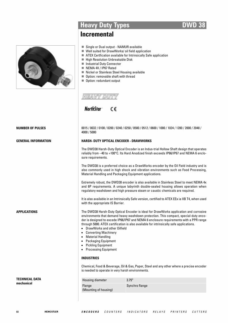
68 E N C O D E R S C O U N T E R S I N D I C A T O R S R E L A Y S P R I N T E R S C U T T E R S
Heavy Duty Types DWD 38Incremental
� Single or Dual output - NAMUR available� Well suited for DrawWorks/ oil field application� ATEX Certfication available for Intrinsically Safe application� High Resolution Unbreakable Disk� Industrial Duty Connector� NEMA 4X / IP67 Rated� Nickel or Stainless Steel Housing available� Option: removable shaft with thread� Option: redundant output
NUMBER OF PULSES 0015 / 0032 / 0100 / 0200 / 0240 / 0250 / 0500 / 0512 / 0600 / 1000 / 1024 / 1200 / 2000 / 2048 /4000 / 5000
GENERAL INFORMATION HARSH- DUTY OPTICAL ENCODER - DRAWWORKS
The DWD38 Harsh-Duty Optical Encoder is an Indus-trial Hollow Shaft design that operatesreliably from −40 to +100°C. Its Hard Anodized finish exceeds IP66/IP67 and NEMA 6 enclo-sure requirements.
The DWD38 is a preferred choice as a DrawWorks encoder by the Oil Field industry and isalso commonly used in high shock and vibration environments such as Food Processing,Material Handling and Packaging Equipment applications.
Extremely robust, the DWD38 encoder is also available in Stainless Steel to meet NEMA 4xand 6P requirements. A unique labyrinth double-sealed housing allows operation whenregulatory washdown and high pressure steam or caustic chemicals are required.
It is also available in an Intrinsically Safe version, certified to ATEX EEx ia IIB T4, when usedwith the appropriate IS Barrier.
APPLICATIONS The DWD38 Harsh-Duty Optical Encoder is ideal for DrawWorks application and corrosiveenvironments that demand heavy washdown protection. This compact, special-duty enco-der is designed to excede IP66/IP67 and NEMA 6 enclosure requirements with a PPR rangethrough 5000. ATEX certification is also available for intrinsically safe applications. • DrawWorks and other Oilfield • Converting Machinery • Material Handling • Packaging Equipment • Pickling Equipment • Processing Equipment
INDUSTRIES
Chemical, Food & Beverage, Oil & Gas, Paper, Steel and any other where a precise encoderis needed to operate in very harsh environments.
TECHNICAL DATA mechanical
Housing diameter 3.75"
Flange (Mounting of housing)
Synchro flange

69E N C O D E R S C O U N T E R S I N D I C A T O R S R E L A Y S P R I N T E R S C U T T E R S
Heavy Duty Types DWD 38Incremental
TECHNICAL DATA mechanical (continued)
Protection class shaft input (EN 60529)
IP67 or NEMA 6
Protection class housing (EN 60529)
IP67 or NEMA 6
Shaft load axial / radial Max:: 100 N / 100 N
Bearing life max. 5 x 10¹¹ revs.
Vibration resistance (DIN EN 60068-2-6)
200 m/s² (5 to 2000 Hz)
Shock resistance (DIN EN 60068-2-27)
500 m/s² (11 msec)
Operating temperature -40 °C ... +100 °CATEX: -40 °C ... +80 °C
Storage temperature -40 °C ... +100 °C
Material shaft Stainless Steel
Material housing Hard anodized Aluminum, Stainless Steel
Connection MS, radialCable, radial
TECHNICAL DATA electrical
Supply voltage DC 5 - 26 VATEX: DC 5 VATEX: DC 5 - 26 V
Max. current w/o load 50 mA
Code Incremental, optical
Max. pulse frequency 125 kHz
Standard output versions
RS422: A, B, N, A, B, NNPN-O.C.: A, B, NPush-pull: A, B, N
ELECTRICAL CONNECTIONS6, 7 & 10 Pin MS connector / Cable
Encoder Function
Cable 6 Pin Single Ended
Cable 7 Pin Single Ended
Cable 7 Pin Dif Line Drv w/o Idx
Cable 10 Pin Dif Line Drv w/ Idx
Cable Exit with Seal
Pin Wire Color Pin Wire Color Pin Wire Color Pin Wire Color Wire Color
Sig. A E brown A brown A brown A brown green
Sig. B D orange B orange B orange B orange blue
Sig. Z C yellow C yellow -- -- C yellow orange
Power +V B red D red D red D red red
Com A black F black F black F black black
Case -- -- G green G green G green white
N/C F -- E -- -- -- E -- --
Sig A -- -- -- -- C brown/white H brown/white violet
Sig B -- -- -- -- E orange/white I orange/white brown
Sig Z -- -- -- -- -- -- J yellow/white yellow

70 E N C O D E R S C O U N T E R S I N D I C A T O R S R E L A Y S P R I N T E R S C U T T E R S
Heavy Duty Types DWD 38Incremental
DIMENSIONED DRAWINGS
<1> With Convertable Shaft<2> With Non-Convertable Shaft<3> Redundant Version<4> 10-32 UNF x .38 deep on Ø 3.000 bolt circle<5> 5/8-18 UNF male thread
<6> 1"-14 UNS female internal thread O-ring sealed<7> 1 "-14 UNS male thread<8> Removable hollow shaft extension included with encoder
Dimensions in inch [mm]

71E N C O D E R S C O U N T E R S I N D I C A T O R S R E L A Y S P R I N T E R S C U T T E R S
Heavy Duty Types DWD 38Incremental
ORDERING INFORMATION
Type Format Numberof pulses
Shaft Ø Output 1, 2 Connection Housing, Tether, Options 3, 4, 5, 6
DWD38 1 Uni-directional
2 Bi-directional
3 Bi-directionalwith Index
15 ... 5000 0 1"-14 UNSx 5/8" - 18UNFThreadedShaft
1 1"-14 UNSThreadedShaft
0 5-26V in, 5-26VOpen Collectorout (7273)
2 5-26V in, 5-26VPush-Pull out
3 5-26V in, 5-26VDifferential LineDriver out (7272)
4 5-26V in, 5V Diffe-rential Line Driverout (7272)
F 5-26V in, 5-26VOpen Collectorout (2222)
G 5-26V in, 5-26VOpen Collectorout with 2.2 kΩPullups (2222)
N NAMUR 15 mAMaximum
1 6 pin connector3 7 pin connector5 10 pin connectorD Sealed cable,
0.45 mF Sealed cabel,
0.15 mG Sealed cable,
0.25 mH Sealed cable,
0.38 m
0 No Options1 Nickel Finish Housing2 Stainless Steel Housing3 Redundant Outputs (Dual
Connector Housing)4 Nickel Finish Housing with
Redundant Outputs5 Stainless Steel Housing with
Redundant OutputsA Same as "0" with ATEX Typ 1B Same as "1" with ATEX Typ 1C Same as "2" with ATEX Typ 1D Same as "3" with ATEX Typ 1E Same as "4" with ATEX Typ 1F Same as "5" with ATEX Typ 1G Same as "0" with ATEX Typ 2H Same as "1" with ATEX Typ 2I Same as "2" with ATEX Typ 2J Same as "3" with ATEX Typ 2K Same as "4" with ATEX Typ 2L Same as "5" with ATEX Typ 2M Same as "0" with ATEX Typ 3N Same as "1" with ATEX Typ 3O Same as "2" with ATEX Typ 3P Same as "3" with ATEX Typ 3Q Same as "4" with ATEX Typ 3R Same as "5" with ATEX Typ 3
1 Output Code "3", "4" only available with Format Code "1", "2" and Connection Code "3" to "H" or with Format Code "3" and Connection Code"5" to "H"
2 Output Code "N" only available with "Number of pulses" Code "0015"3 Available ATEX certified options:
ATEX Type 1: 5 V in, 5 V out ATEX Type 2: 7-26V in, 7-26V out ATEX Type 3: 7-26V in, 5V outNote: When selecting ATEX models, ATEX voltages replace those shown in Output Code.
4 Housing/Tether/Options Code "G" to "L" only available with Output Code "0" to "3", "F" or "G" 5 Housing/Tether/Options Code "M" to "R" only available with Output Code "4"6 Note for Housing with redundant outputs: Simultaneous use of redundant outputs may void ATEX certification. Consult us for details.

72 E N C O D E R S C O U N T E R S I N D I C A T O R S R E L A Y S P R I N T E R S C U T T E R S
Heavy Duty Types AR 62/63Absolute BiSS / SSI
AR 62 with cable outlet
AR 62 with M12 connector
� Singleturn 12 Bit Resolution� 300 N axial and radial load� 200 g shock resistance� 20 g vibrations resistance� Submersible: Protection class up to IP69k� High temperature range: -40 ... +100°C� Compact design: 32 mm mounting depth� Option: Stainless steel housing� Option: Control inputs Preset and Direction
GENERAL INFORMATION ACURO-XR - THE ROBUST ENCODER FOR ALL ENVIRONMENTAL CONDITIONS!
The special features of the new ACURO-XR series not only comprise its particularly ruggedenclosure, but also generously dimensioned, rigid ball-bearings. Capable of withstandingeven high axial and radial loads on its shaft axis, this encoder type easily achieves a mecha-nical life of 10 9 rotations at a permanent radial load of 200 N and simultaneously, an axial loadof 200N.
The newly designed ACURO-XR makes a difference. It easily withstands highest acceler-ations, extreme climatic fluctuations and even underwater operation. In this way, our rugged absolute encoder is ideally suitable for applications in wind farms, marine or utilityvehicle applications, as well as for use in presses or wood and stone processing machinery:applications where high resistance to harsh environments and maximum reliability arerequired at the same time.
The AR62 is electrically compatible with standard encoders and operates with the magne-tic technology. Available interfaces are SSI, BiSS, CANopen and Analogue (0 ... 10 V or 4 ... 20 mA).
With an installed depth of only 32 mm, this encoder is the most compact type in its class. Valuable space has been saved − to the benefit of the overall machinery design.
APPLICATIONS Fields of application that clearly unfold the benefits of ACURO-XR: • Construction machinery • Utility vehicles / trucks • Gantry cranes • Marine equipment • Offshore plants • Wind power plants • Commercial solar plants • Food & Beverage Industry • Filling plants • Presses • Your individual application

73E N C O D E R S C O U N T E R S I N D I C A T O R S R E L A Y S P R I N T E R S C U T T E R S
Heavy Duty Types AR 62/63Absolute BiSS / SSI
TECHNICAL DATA mechanical
Housing diameter 58 mm
Mounting depth 32 mm
Shaft diameter 10 mm / 12 mm (Solid shaft)
Flange (Mounting of housing)
Synchro clamping flange
Protection class shaft input (EN 60529)
IP67 or IP69k
Protection class housing (EN 60529)
IP67 or IP69k
Shaft load axial / radial max.: 300 N / 300 N
Max. speed max. 5000 rpm
Vibration resistance (DIN EN 60068-2-6)
200 m/s²
Shock resistance (DIN EN 60068-2-27)
2000 m/s² (6 ms)
Operating temperature -40 °C ... +100 °C
Connection Cable, radialM12-connector, radial
TECHNICAL DATA electrical
Supply voltage DC 10-30 V
Max. current w/o load 50 mA (24 V)
EMC EN 61326 Class A
Resolution singleturn 12 Bit
Output code Gray
Repeatability ±0,2°
Control inputs 1 Preset, Direction1 Preset, Direction optional available
ELECTRICAL CONNECTIONSCable
Color cable Signal
yellow Clock
pink Data
green Clock
grey Data
white UB
brown 0 V
Screen Screen
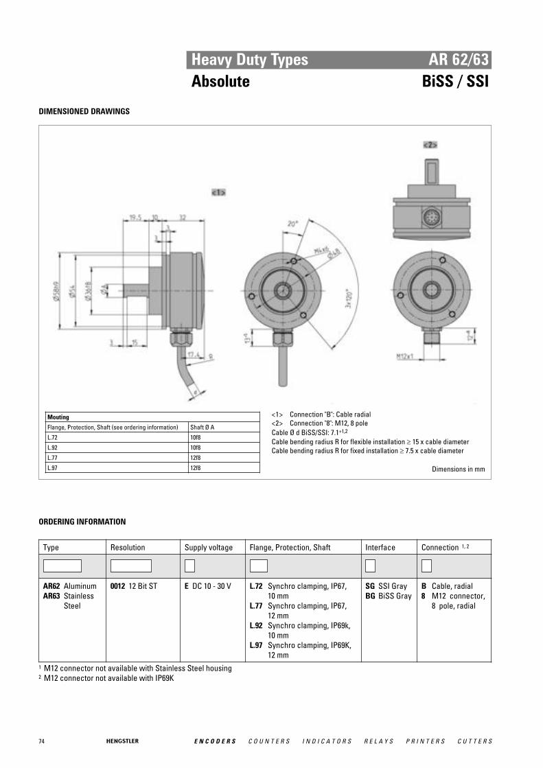
74 E N C O D E R S C O U N T E R S I N D I C A T O R S R E L A Y S P R I N T E R S C U T T E R S
Heavy Duty Types AR 62/63Absolute BiSS / SSI
DIMENSIONED DRAWINGS
Mouting
Flange, Protection, Shaft (see ordering information) Shaft Ø A
L.72 10f8
L.92 10f8
L.77 12f8
L.97 12f8
<1> Connection "B": Cable radial<2> Connection "8": M12, 8 poleCable Ø d BiSS/SSI: 7.1+1,2
Cable bending radius R for flexible installation ≥ 15 x cable diameterCable bending radius R for fixed installation ≥ 7.5 x cable diameter
Dimensions in mm
ORDERING INFORMATION
Type Resolution Supply voltage Flange, Protection, Shaft Interface Connection 1, 2
AR62 AluminumAR63 Stainless
Steel
0012 12 Bit ST E DC 10 - 30 V L.72 Synchro clamping, IP67, 10 mm
L.77 Synchro clamping, IP67, 12 mm
L.92 Synchro clamping, IP69k,10 mm
L.97 Synchro clamping, IP69K,12 mm
SG SSI GrayBG BiSS Gray
B Cable, radial8 M12 connector,
8 pole, radial
1 M12 connector not available with Stainless Steel housing2 M12 connector not available with IP69K

75E N C O D E R S C O U N T E R S I N D I C A T O R S R E L A Y S P R I N T E R S C U T T E R S
Heavy Duty Types AR 62/63Absolute BiSS / SSI
ORDERING INFORMATION Selection of cable length
Versions with cable outlet (connection A, B, E or F) are available with various lengths ofcable. To order your desired cable length, please add the respective code to the end ofyour ordering code. Further cable lengths on request.
Code Cable length
without code 1.5 m
-D0 3 m
-F0 5 m
-K0 10 m
-P0 15 m
-U0 20 m
-V0 25 m

76 E N C O D E R S C O U N T E R S I N D I C A T O R S R E L A Y S P R I N T E R S C U T T E R S
Heavy Duty Types AR 62/63Absolute CANopen
AR 62 with cable outlet
AR 62 with M12 connector
� Singleturn 12 Bit Resolution� 300 N axial and radial load� 200 g shock resistance� 20 g vibration resistance� Submersible: Protection class up to IP69K� High temperature range: -40 ... +100°C� Compact design: 32 mm mounting depth� Option: Stainless steel housing
GENERAL INFORMATION ACURO-XR - THE ROBUST ENCODER FOR ALL ENVIRONMENTAL CONDITIONS!
The special features of the new ACURO-XR series not only comprise its particularly ruggedenclosure, but also generously dimensioned, rigid ball-bearings. Capable of withstandingeven high axial and radial loads on its shaft axis, this encoder type easily achieves a mecha-nical life of 10 9 rotations at a permanent radial load of 200 N and simultaneously, an axial loadof 200N.
The newly designed ACURO-XR makes a difference. It easily withstands highest accelerati-ons, extreme climatic fluctuations and even underwater operation. In this way, our ruggedabsolute encoder is ideally suitable for applications in wind farms, marine or utility vehicleapplications, as well as for use in presses or wood and stone processing machinery: appli-cations where high resistance to harsh environments and maximum reliability are requiredat the same time.
The AR62 is electrically compatible with standard encoders and operates with the magne-tic technology. Available interfaces are SSI, BiSS, CANopen and Analogue (0 ... 10 V or 4 ... 20 mA).
With an installed depth of only 32 mm, this encoder is the most compact type in its class. Valuable space has been saved − to the benefit of the overall machinery design.
APPLICATIONS Fields of application that clearly unfold the benefits of ACURO-XR: • Construction machinery • Utility vehicles / trucks • Gantry cranes • Marine equipment • Offshore plants • Wind power plants • Commercial solar plants • Food & Beverage Industry • Filling plants • Presses • Your individual application

77E N C O D E R S C O U N T E R S I N D I C A T O R S R E L A Y S P R I N T E R S C U T T E R S
Heavy Duty Types AR 62/63Absolute CANopen
TECHNICAL DATA mechanical
Housing diameter 58 mm
Mounting depth 32 mm
Shaft diameter 10 mm / 12 mm (Solid shaft)
Flange (Mounting of housing)
Synchro clamping flange
Protection class shaft input (EN 60529)
IP67 or IP69k
Protection class housing (EN 60529)
IP67 or IP69k
Shaft load axial / radial max.: 300 N / 300 N
Max. speed max. 5000 rpm
Vibration resistance (DIN EN 60068-2-6)
200 m/s²
Shock resistance (DIN EN 60068-2-27)
2000 m/s² (6 ms)
Operating temperature -40 °C ... +100 °C
Connection Cable, radialM12-connector, radial
TECHNICAL DATA electrical
Supply voltage DC 10-30 V
Max. current w/o load 220 mA
EMC EN 61326 Class A
Resolution singleturn 12 Bit
Output code Binary
Interface CAN High-Speed according to ISO/DIS 11898
Profile/ protocol CANopen according to DS 301 with profile DSP 406, pro-grammable encoder according class C2
Repeatability ±0,2°
Parametrization Scaling, Preset, Offset, Direction
Integrated special functions Speed, Acceleration, Limit values
ELECTRICAL CONNECTIONSCable
Color cable Cable pairs Signal
yellow Pair 1 CAN in+
green CAN in-
pink Pair 2 CAN out+
grey CAN out-
blue n.c.
red n.c.
white Pair 3 UB
brown 0 V
Screen Screen Screen

78 E N C O D E R S C O U N T E R S I N D I C A T O R S R E L A Y S P R I N T E R S C U T T E R S
Heavy Duty Types AR 62/63Absolute CANopen
DIMENSIONED DRAWINGS
Mouting
Flange, Protection, Shaft (see ordering information) Shaft Ø A
L.72 10f8
L.92 10f8
L.77 12f8
L.97 12f8
<1> Connection "B": Cable radial<2> Connection "8": M12, 8 poleCable Ø d BiSS/SSI: 7.1+1,2
Cable bending radius R for flexible installation ≥ 15 x cable diameterCable bending radius R for fixed installation ≥ 7.5 x cable diameter
Dimensions in mm
ORDERING INFORMATION
Type Resolution Supply voltage Flange, Protection, Shaft Interface Connection 1, 2
AR62 AluminumAR63 Stainless
Steel
0012 12 Bit ST E DC 10 - 30 V L.72 Synchro clamping, IP67,10 mm
L.77 Synchro clamping, IP67,12 mm
L.92 Synchro clamping, IP69k,10 mm
L.97 Synchro clamping, IP69K,12 mm
OL CANopen B Cable, radial8 M12 connector,
8 pole, radial
1 M12 connector not available with Stainless steel housing (AR63)2 M12 connector not available with IP69K

79E N C O D E R S C O U N T E R S I N D I C A T O R S R E L A Y S P R I N T E R S C U T T E R S
Heavy Duty Types AR 62/63Absolute CANopen
ORDERING INFORMATION Selection of cable length
Versions with cable outlet (connection A, B, E or F) are available with various lengths ofcable. To order your desired cable length, please add the respective code to the end ofyour ordering code. Further cable lengths on request.
Code Cable length
without code 1.5 m
-D0 3 m
-F0 5 m
-K0 10 m
-P0 15 m
-U0 20 m
-V0 25 m
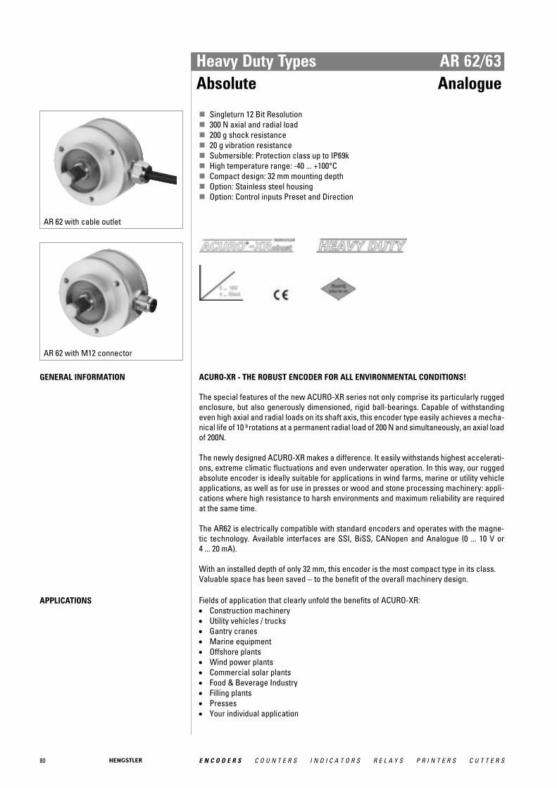
80 E N C O D E R S C O U N T E R S I N D I C A T O R S R E L A Y S P R I N T E R S C U T T E R S
Heavy Duty Types AR 62/63Absolute Analogue
AR 62 with cable outlet
AR 62 with M12 connector
� Singleturn 12 Bit Resolution� 300 N axial and radial load� 200 g shock resistance� 20 g vibration resistance� Submersible: Protection class up to IP69k� High temperature range: -40 ... +100°C� Compact design: 32 mm mounting depth� Option: Stainless steel housing� Option: Control inputs Preset and Direction
GENERAL INFORMATION ACURO-XR - THE ROBUST ENCODER FOR ALL ENVIRONMENTAL CONDITIONS!
The special features of the new ACURO-XR series not only comprise its particularly ruggedenclosure, but also generously dimensioned, rigid ball-bearings. Capable of withstandingeven high axial and radial loads on its shaft axis, this encoder type easily achieves a mecha-nical life of 10 9 rotations at a permanent radial load of 200 N and simultaneously, an axial loadof 200N.
The newly designed ACURO-XR makes a difference. It easily withstands highest accelerati-ons, extreme climatic fluctuations and even underwater operation. In this way, our ruggedabsolute encoder is ideally suitable for applications in wind farms, marine or utility vehicleapplications, as well as for use in presses or wood and stone processing machinery: appli-cations where high resistance to harsh environments and maximum reliability are requiredat the same time.
The AR62 is electrically compatible with standard encoders and operates with the magne-tic technology. Available interfaces are SSI, BiSS, CANopen and Analogue (0 ... 10 V or 4 ... 20 mA).
With an installed depth of only 32 mm, this encoder is the most compact type in its class. Valuable space has been saved − to the benefit of the overall machinery design.
APPLICATIONS Fields of application that clearly unfold the benefits of ACURO-XR: • Construction machinery • Utility vehicles / trucks • Gantry cranes • Marine equipment • Offshore plants • Wind power plants • Commercial solar plants • Food & Beverage Industry • Filling plants • Presses • Your individual application
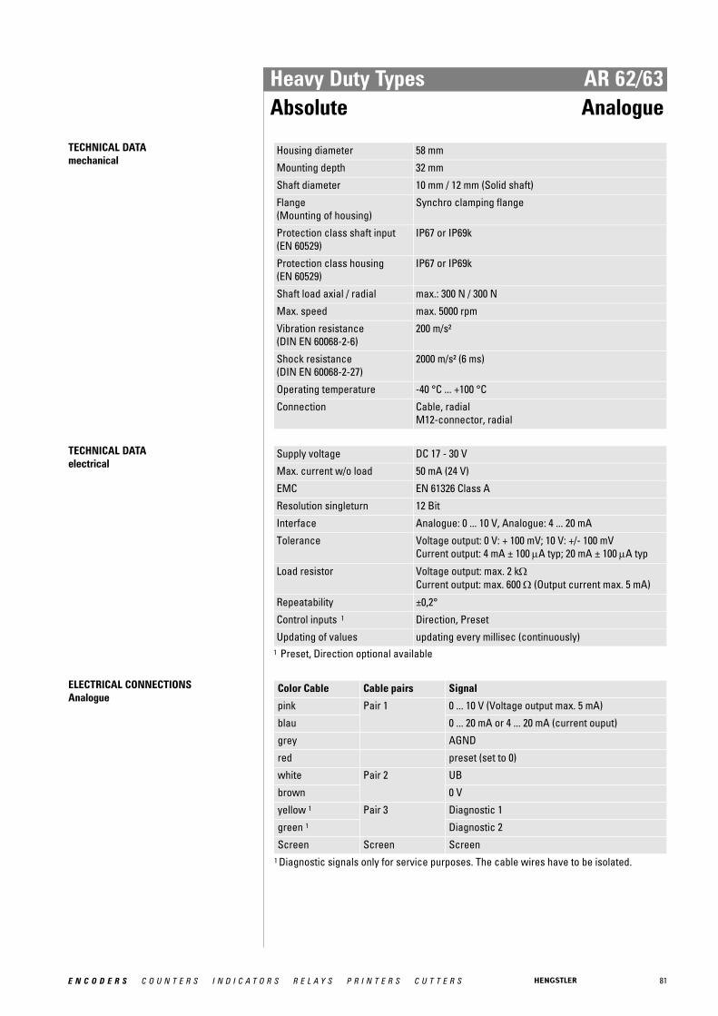
81E N C O D E R S C O U N T E R S I N D I C A T O R S R E L A Y S P R I N T E R S C U T T E R S
Heavy Duty Types AR 62/63Absolute Analogue
TECHNICAL DATA mechanical
Housing diameter 58 mm
Mounting depth 32 mm
Shaft diameter 10 mm / 12 mm (Solid shaft)
Flange (Mounting of housing)
Synchro clamping flange
Protection class shaft input (EN 60529)
IP67 or IP69k
Protection class housing (EN 60529)
IP67 or IP69k
Shaft load axial / radial max.: 300 N / 300 N
Max. speed max. 5000 rpm
Vibration resistance (DIN EN 60068-2-6)
200 m/s²
Shock resistance (DIN EN 60068-2-27)
2000 m/s² (6 ms)
Operating temperature -40 °C ... +100 °C
Connection Cable, radialM12-connector, radial
TECHNICAL DATA electrical
Supply voltage DC 17 - 30 V
Max. current w/o load 50 mA (24 V)
EMC EN 61326 Class A
Resolution singleturn 12 Bit
Interface Analogue: 0 ... 10 V, Analogue: 4 ... 20 mA
Tolerance Voltage output: 0 V: + 100 mV; 10 V: +/- 100 mVCurrent output: 4 mA ± 100 μA typ; 20 mA ± 100 μA typ
Load resistor Voltage output: max. 2 kΩCurrent output: max. 600 Ω (Output current max. 5 mA)
Repeatability ±0,2°
Control inputs 1 Direction, Preset
Updating of values updating every millisec (continuously)1 Preset, Direction optional available
ELECTRICAL CONNECTIONSAnalogue
Color Cable Cable pairs Signal
pink Pair 1 0 ... 10 V (Voltage output max. 5 mA)
blau 0 ... 20 mA or 4 ... 20 mA (current ouput)
grey AGND
red preset (set to 0)
white Pair 2 UB
brown 0 V
yellow 1 Pair 3 Diagnostic 1
green 1 Diagnostic 2
Screen Screen Screen 1 Diagnostic signals only for service purposes. The cable wires have to be isolated.
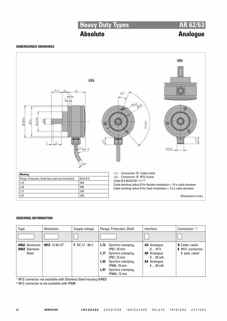
82 E N C O D E R S C O U N T E R S I N D I C A T O R S R E L A Y S P R I N T E R S C U T T E R S
Heavy Duty Types AR 62/63Absolute Analogue
DIMENSIONED DRAWINGS
Mouting
Flange, Protection, Shaft (see ordering information) Shaft Ø A
L.72 10f8
L.92 10f8
L.77 12f8
L.97 12f8
<1> Connection "B": Cable radial<2> Connection "8": M12, 8 poleCable Ø d BiSS/SSI: 7.1+1,2
Cable bending radius R for flexible installation ≥ 15 x cable diameterCable bending radius R for fixed installation ≥ 7.5 x cable diameter
Dimensions in mm
ORDERING INFORMATION
Type Resolution Supply voltage Flange, Protection, Shaft Interface Connection 1, 2
AR62 AluminumAR63 Stainless
Steel
0012 12 Bit ST F DC 17 - 30 V L.72 Synchro clamping,IP67, 10 mm
L.77 Synchro clamping,IP67, 12 mm
L.92 Synchro clamping,IP69k, 10 mm
L.97 Synchro clamping,IP69K, 12 mm
AV Analogue 0 ... 10 V
A0 Analogue 0 ... 20 mA
A4 Analogue 4 ... 20 mA
B Cable, radial8 M12 connector,
8 pole, radial
1 M12 connector not available with Stainless Steel housing (AR63)2 M12 connector is not available with IP69K

83E N C O D E R S C O U N T E R S I N D I C A T O R S R E L A Y S P R I N T E R S C U T T E R S
Heavy Duty Types AR 62/63Absolute Analogue
ORDERING INFORMATION Selection of cable length
Versions with cable outlet (connection A, B, E or F) are available with various lengths ofcable. To order your desired cable length, please add the respective code to the end ofyour ordering code. Further cable lengths on request.
Code Cable length
without code 1.5 m
-D0 3 m
-F0 5 m
-K0 10 m
-P0 15 m
-U0 20 m
-V0 25 m

Standard Industrial Types Incremental
84 E N C O D E R S C O U N T E R S I N D I C A T O R S R E L A Y S P R I N T E R S C U T T E R S
Incremental encoders are sensors capable of generating signals in response to rotary movement. In conjunction with mechanical conversion devices, such as rack-and-pinions, measuring wheels orspindles, incremental shaft encoders can also be used to measurelinear movement. The shaft encoder generates a signal for eachincremental change in position.
With the optical transformation, a line-coded disc made of metal,plastic or glass and positioned on a rotary bearing interrupts theinfra red light ray emitted by gallium arsenid sender diode. The number of lines determines the resolution, i.e. the measuring pointswithin a revolution. The interruptions of the light ray are sensed by thereceptor element and electronically processed. The information isthen made available as a rectangular signal at the encoder output.
■ Door closing devices for trains■ Desktop robots■ Lens grinding machines■ Plotters■ Testing machines
for optical waveguides■ Scattering machines■ Tampon printing machines
■ Ultrasonic welding■ Screwing machines■ Labelling machines■ x/y indication■ Analysis devices■ Drilling machines■ Mixing machines
Examples for typical applications of incremental encoders:
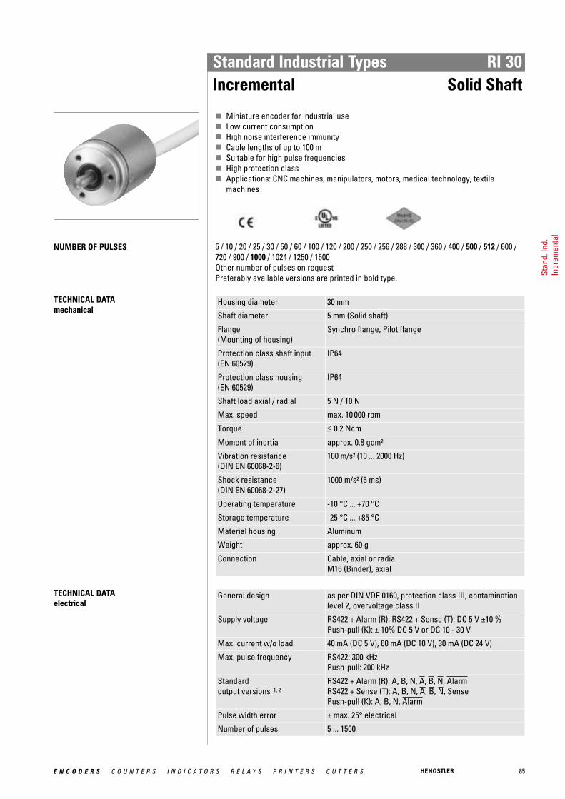
85E N C O D E R S C O U N T E R S I N D I C A T O R S R E L A Y S P R I N T E R S C U T T E R S
Standard Industrial Types RI 30Incremental Solid Shaft
� Miniature encoder for industrial use� Low current consumption� High noise interference immunity� Cable lengths of up to 100 m� Suitable for high pulse frequencies� High protection class� Applications: CNC machines, manipulators, motors, medical technology, textile
machines
NUMBER OF PULSES 5 / 10 / 20 / 25 / 30 / 50 / 60 / 100 / 120 / 200 / 250 / 256 / 288 / 300 / 360 / 400 / 500 / 512 / 600 /720 / 900 / 1000 / 1024 / 1250 / 1500 Other number of pulses on request Preferably available versions are printed in bold type.
TECHNICAL DATA mechanical
Housing diameter 30 mm
Shaft diameter 5 mm (Solid shaft)
Flange (Mounting of housing)
Synchro flange, Pilot flange
Protection class shaft input (EN 60529)
IP64
Protection class housing (EN 60529)
IP64
Shaft load axial / radial 5 N / 10 N
Max. speed max. 10 000 rpm
Torque ≤ 0.2 Ncm
Moment of inertia approx. 0.8 gcm²
Vibration resistance (DIN EN 60068-2-6)
100 m/s² (10 ... 2000 Hz)
Shock resistance (DIN EN 60068-2-27)
1000 m/s² (6 ms)
Operating temperature -10 °C ... +70 °C
Storage temperature -25 °C ... +85 °C
Material housing Aluminum
Weight approx. 60 g
Connection Cable, axial or radialM16 (Binder), axial
TECHNICAL DATA electrical
General design as per DIN VDE 0160, protection class III, contaminationlevel 2, overvoltage class II
Supply voltage RS422 + Alarm (R), RS422 + Sense (T): DC 5 V ±10 % Push-pull (K): ± 10% DC 5 V or DC 10 - 30 V
Max. current w/o load 40 mA (DC 5 V), 60 mA (DC 10 V), 30 mA (DC 24 V)
Max. pulse frequency RS422: 300 kHzPush-pull: 200 kHz
Standard output versions 1, 2
RS422 + Alarm (R): A, B, N, A, B, N, AlarmRS422 + Sense (T): A, B, N, A, B, N, SensePush-pull (K): A, B, N, Alarm
Pulse width error ± max. 25° electrical
Number of pulses 5 ... 1500
Stan
d. In
d.In
crem
enta
l
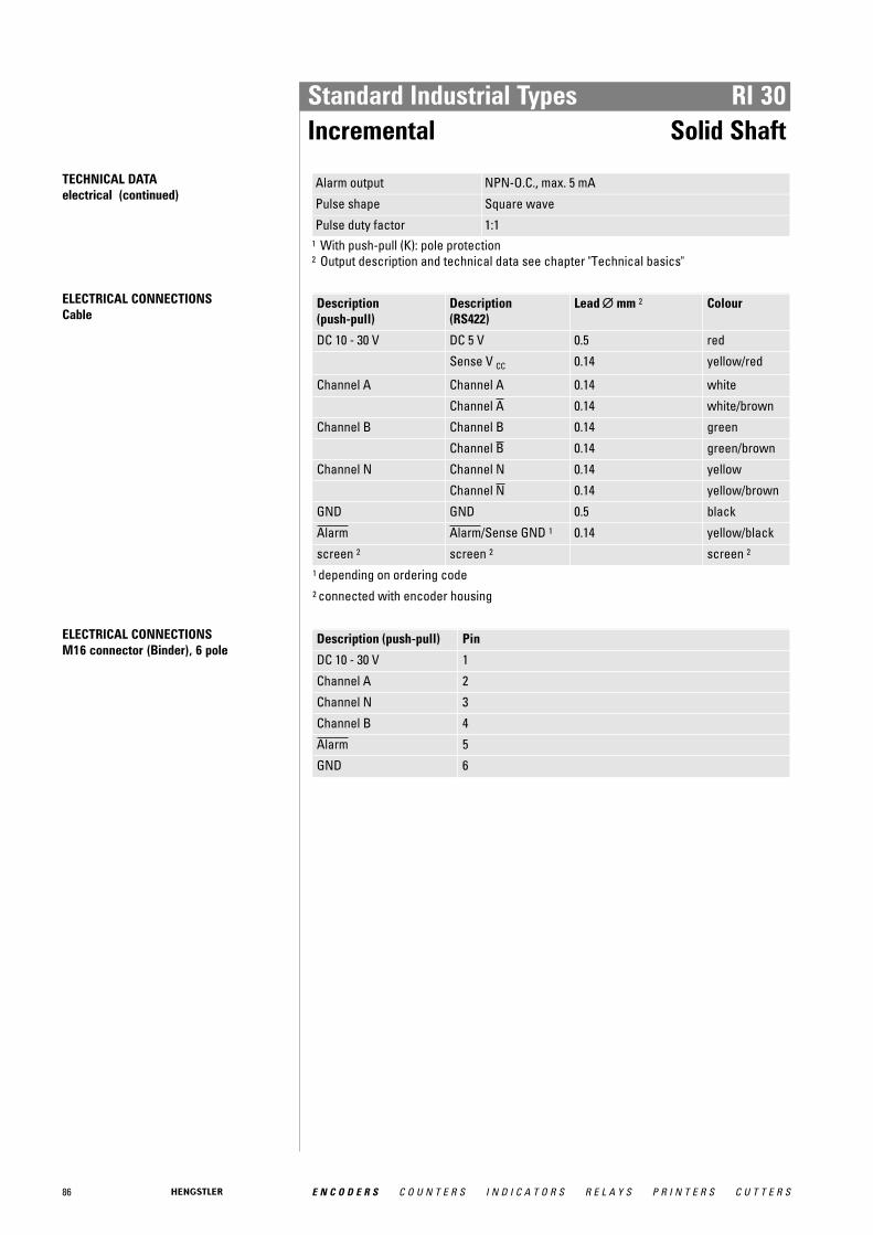
86 E N C O D E R S C O U N T E R S I N D I C A T O R S R E L A Y S P R I N T E R S C U T T E R S
Standard Industrial Types RI 30Incremental Solid Shaft
TECHNICAL DATA electrical (continued)
Alarm output NPN-O.C., max. 5 mA
Pulse shape Square wave
Pulse duty factor 1:11 With push-pull (K): pole protection2 Output description and technical data see chapter "Technical basics"
ELECTRICAL CONNECTIONSCable
Description (push-pull)
Description (RS422)
Lead ∅∅ mm 2 Colour
DC 10 - 30 V DC 5 V 0.5 red
Sense V CC 0.14 yellow/red
Channel A Channel A 0.14 white
Channel A 0.14 white/brown
Channel B Channel B 0.14 green
Channel B 0.14 green/brown
Channel N Channel N 0.14 yellow
Channel N 0.14 yellow/brown
GND GND 0.5 black
Alarm Alarm/Sense GND 1 0.14 yellow/black
screen 2 screen 2 screen 2
1 depending on ordering code 2 connected with encoder housing
ELECTRICAL CONNECTIONSM16 connector (Binder), 6 pole
Description (push-pull) Pin
DC 10 - 30 V 1
Channel A 2
Channel N 3
Channel B 4
Alarm 5
GND 6
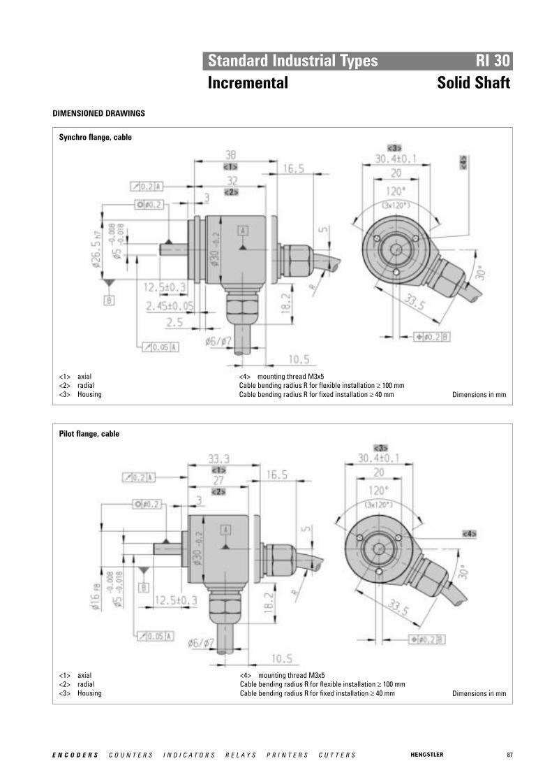
87E N C O D E R S C O U N T E R S I N D I C A T O R S R E L A Y S P R I N T E R S C U T T E R S
Standard Industrial Types RI 30Incremental Solid Shaft
DIMENSIONED DRAWINGS
Synchro flange, cable
<1> axial<2> radial<3> Housing
<4> mounting thread M3x5Cable bending radius R for flexible installation ≥ 100 mmCable bending radius R for fixed installation ≥ 40 mm Dimensions in mm
Pilot flange, cable
<1> axial<2> radial<3> Housing
<4> mounting thread M3x5Cable bending radius R for flexible installation ≥ 100 mmCable bending radius R for fixed installation ≥ 40 mm Dimensions in mm

88 E N C O D E R S C O U N T E R S I N D I C A T O R S R E L A Y S P R I N T E R S C U T T E R S
Standard Industrial Types RI 30Incremental Solid Shaft
DIMENSIONED DRAWINGS (continued)
Synchro flange, M16 (Binder)
<1> 6 pole (pins)<2> mounting thread M3x5
<3> HousingDimensions in mm
Pilot flange, M16 (Binder)
<1> 6 pole (pins)<2> mounting thread M3x5
<3> HousingDimensions in mm

89E N C O D E R S C O U N T E R S I N D I C A T O R S R E L A Y S P R I N T E R S C U T T E R S
Standard Industrial Types RI 30Incremental Solid Shaft
ORDERING INFORMATION Selection of cable length
Versions with cable outlet (connection A, B, E or F) are available with various lengths ofcable. To order your desired cable length, please add the respective code to the end ofyour ordering code. Further cable lengths on request.
Code Cable length
without code 1.5 m
-D0 3 m
-F0 5 m
-K0 10 m
-P0 15 m
-U0 20 m
-V0 25 m
ACCESSORIES see chapter "Accessories", starting page 322
ORDERING INFORMATION
Type Number ofpulses
Supply voltage1
Flange, Protection, Shaft Output 2 Connection 3
RI30-O 5 ... 1500 A DC 5 VE DC 10 - 30 V
S.34 Synchro, IP64, 5 mmR.34 Pilot, IP64, 5 mm
R RS422 +AlarmT RS422 +SenseK Push-pull
A Cable, axialB Cable, radialE-I M23 connector (Conin) at 1 m
TPE cable, cwE-D M23 connector (Conin) at 1 m
TPE cable, ccwN M16 connector (Binder), 6 pole,
axial1 DC 10 - 30 V only with push-pull2 Output code "K": short-circuit-proof3 For Output Code "N" (M16): only push-pull
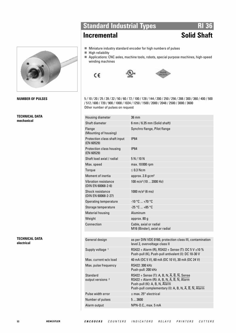
90 E N C O D E R S C O U N T E R S I N D I C A T O R S R E L A Y S P R I N T E R S C U T T E R S
Standard Industrial Types RI 36Incremental Solid Shaft
� Miniature industry standard encoder for high numbers of pulses� High reliability� Applications: CNC axles, machine tools, robots, special purpose machines, high-speed
winding machines
NUMBER OF PULSES 5 / 10 / 20 / 25 / 28 / 32 / 50 / 60 / 72 / 100 / 128 / 144 / 200 / 250 / 256 / 288 / 300 / 360 / 400 / 500/ 512 / 600 / 720 / 900 / 1000 / 1024 / 1250 / 1500 / 2000 / 2048 / 2500 / 3000 / 3600 Other number of pulses on request
TECHNICAL DATA mechanical
Housing diameter 36 mm
Shaft diameter 6 mm / 6.35 mm (Solid shaft)
Flange (Mounting of housing)
Synchro flange, Pilot flange
Protection class shaft input (EN 60529)
IP64
Protection class housing (EN 60529)
IP64
Shaft load axial / radial 5 N / 10 N
Max. speed max. 10 000 rpm
Torque ≤ 0.3 Ncm
Moment of inertia approx. 2.8 gcm²
Vibration resistance (DIN EN 60068-2-6)
100 m/s² (10 ... 2000 Hz)
Shock resistance (DIN EN 60068-2-27)
1000 m/s² (6 ms)
Operating temperature -10 °C ... +70 °C
Storage temperature -25 °C ... +85 °C
Material housing Aluminum
Weight approx. 80 g
Connection Cable, axial or radialM16 (Binder), axial or radial
TECHNICAL DATA electrical
General design as per DIN VDE 0160, protection class III, contaminationlevel 2, overvoltage class II
Supply voltage 1 RS422 + Alarm (R), RS422 + Sense (T): DC 5 V ±10 % Push-pull (K), Push-pull antivalent (I): DC 10-30 V
Max. current w/o load 40 mA (DC 5 V), 60 mA (DC 10 V), 30 mA (DC 24 V)
Max. pulse frequency RS422: 300 kHzPush-pull: 200 kHz
Standard output versions 2
RS422 + Sense (T): A, B, N, A, B, N, SenseRS422 + Alarm (R): A, B, N, A, B, N, AlarmPush-pull (K): A, B, N, AlarmPush-pull complementary (I): A, B, N, A, B, N, Alarm
Pulse width error ± max. 25° electrical
Number of pulses 5 ... 3600
Alarm output NPN-O.C., max. 5 mA

91E N C O D E R S C O U N T E R S I N D I C A T O R S R E L A Y S P R I N T E R S C U T T E R S
Standard Industrial Types RI 36Incremental Solid Shaft
TECHNICAL DATA electrical (continued)
Pulse shape Square wave
Pulse duty factor 1:11 With push-pull (K) and push-pull complementary (I): pole protection2 Output description and technical data see chapter "Technical basics"
ELECTRICAL CONNECTIONSCable PVC
Cable PVC (A, B) Output
Colour Lead mm 2
RS422 (R, T)
push-pull (K)
push-pull complementary (I)
red 0.5 DC 5 V DC 10 - 30 V DC 10 - 30 V
yellow/red 0.14 Sense V CC Sense V CC
white 0.14 Channel A Channel A Channel A
white/brown 0.14 Channel A Channel A
green 0.14 Channel B Channel B Channel B
green/brown 0.14 Channel B Channel B
yellow 0.14 Channel N Channel N Channel N
yellow/brown 0.14 Channel N Channel N
black 0.5 GND GND GND
yellow/black 0.14 Alarm/Sense GND 1 Alarm Alarm
screen 2 screen 2 screen 2 screen 2
1 depending on ordering code 2 connected with encoder housing
ELECTRICAL CONNECTIONSM16 connector (Binder), 6 pole
Description (push-pull)
Pin
DC 10 - 30 V 1
Channel A 2
Channel N 3
Channel B 4
Alarm 5
GND 6

92 E N C O D E R S C O U N T E R S I N D I C A T O R S R E L A Y S P R I N T E R S C U T T E R S
Standard Industrial Types RI 36Incremental Solid Shaft
DIMENSIONED DRAWINGS
Synchro flange
<1> axial<2> radial<3> mounting thread M3x5<4> Housing<5> 6 pole (pins)
Cable bending radius R for flexible installation ≥ 100 mmCable bending radius R for fixed installation ≥ 40 mm
Dimensions in mm
Pilot flange
<1> axial<2> radial<3> mounting thread M3x5<4> Housing<5> 6 pole (pins)
Cable bending radius R for flexible installation ≥ 100 mmCable bending radius R for fixed installation ≥ 40 mm
Dimensions in mm
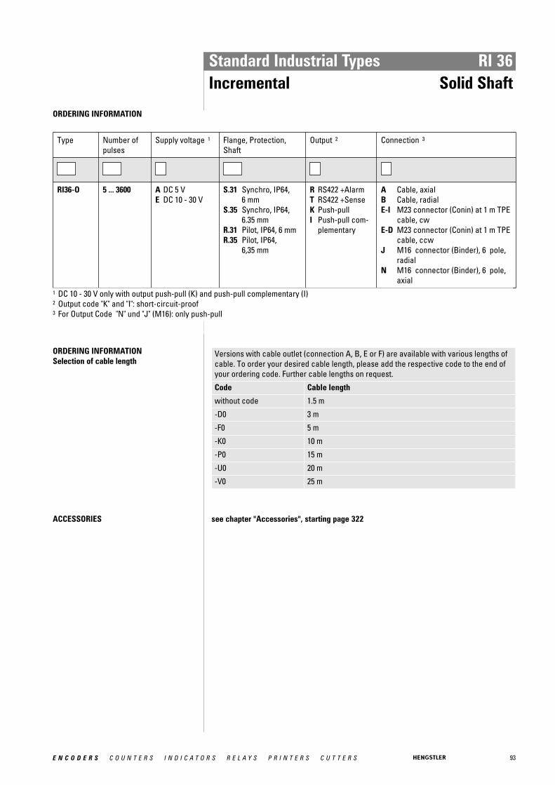
93E N C O D E R S C O U N T E R S I N D I C A T O R S R E L A Y S P R I N T E R S C U T T E R S
Standard Industrial Types RI 36Incremental Solid Shaft
ORDERING INFORMATION
Type Number ofpulses
Supply voltage 1 Flange, Protection,Shaft
Output 2 Connection 3
RI36-O 5 ... 3600 A DC 5 VE DC 10 - 30 V
S.31 Synchro, IP64, 6 mm
S.35 Synchro, IP64,6.35 mm
R.31 Pilot, IP64, 6 mmR.35 Pilot, IP64,
6,35 mm
R RS422 +AlarmT RS422 +SenseK Push-pullI Push-pull com-
plementary
A Cable, axialB Cable, radialE-I M23 connector (Conin) at 1 m TPE
cable, cwE-D M23 connector (Conin) at 1 m TPE
cable, ccwJ M16 connector (Binder), 6 pole,
radialN M16 connector (Binder), 6 pole,
axial1 DC 10 - 30 V only with output push-pull (K) and push-pull complementary (I)2 Output code "K" and "I": short-circuit-proof3 For Output Code "N" und "J" (M16): only push-pull
ORDERING INFORMATION Selection of cable length
Versions with cable outlet (connection A, B, E or F) are available with various lengths ofcable. To order your desired cable length, please add the respective code to the end ofyour ordering code. Further cable lengths on request.
Code Cable length
without code 1.5 m
-D0 3 m
-F0 5 m
-K0 10 m
-P0 15 m
-U0 20 m
-V0 25 m
ACCESSORIES see chapter "Accessories", starting page 322

94 E N C O D E R S C O U N T E R S I N D I C A T O R S R E L A Y S P R I N T E R S C U T T E R S
Standard Industrial Types RI 58-O / RI 58-TIncremental Solid Shaft
Synchro flange
Clamping flange
� Universal industry standard encoder� Up to 40 000 steps with 10 000 pulses� High signal accuracy� Protection class up to IP67� Flexible due to many flange and configuration variants� Suitable for high shock ratings� Applications: machine tools, CNC axles, packing machines, motors/ drives, injection
moulding machines, sawing machines, textile machines� For EX version, see RX 70-l� Operating temperature up to 100 °C (RI 58-T)
NUMBER OF PULSES RI 58-O 1 / 2 / 3 / 4 / 5 / 10 / 15 / 20 / 25 / 30 / 35 / 40 / 45 / 50 / 60 / 64 / 70 / 72 / 80 / 100 / 125 / 128 / 144/ 150 / 180 / 200 / 230 / 250 / 256 / 300 / 314 / 350 / 360 / 375 / 400 / 460 / 480 / 500 / 512 / 600 /625 / 635 / 720 / 750 / 900 / 1000 / 1024 / 1200 / 1250 / 1500 / 1600 / 1800 / 2000 / 2048 / 2500 /3000 / 3480 / 3600 / 3750 / 3968 / 4000 / 4096 / 4800 / 5000 / 5400 / 6000 / 7200 / 7680 / 8000 /8192 / 9000 / 10000 Other number of pulses on request Preferably available versions are printed in bold type.
RI 58-T 4 / 5 / 10 / 15 / 20 / 25 / 30 / 35 / 40 / 45 / 50 / 60 / 64 / 70 / 72 / 80 / 100 / 125 / 128 / 144 / 150 /180 / 200 / 230 / 250 / 256 / 300 / 314 / 350 / 360 / 375 / 400 / 460 / 480 / 500 / 512 / 600 / 625 /635 / 720 / 750 / 900 / 1000 / 1024 / 1200 / 1250 / 1500 / 1600 / 1800 / 2000 / 2048 / 2500 Other number of pulses on request Preferably available versions are printed in bold type.
TECHNICAL DATA mechanical
Housing diameter 58 mm
Shaft diameter 6 mm / 6.35 mm / 7 mm / 9.52 mm / 10 mm / 12 mm (Solidshaft)
Flange (Mounting of housing)
Synchro flange, Clamping flange, Square flange, Synchroclamping flange
Protection class shaft input (EN 60529)
IP64 or IP67
Protection class housing (EN 60529)
IP65 or IP67
Shaft load axial / radial Ø 6 mm / 6,35 mm: 20 N / 40 NØ 7 ... 10 mm: 40 N / 60 NØ 12 mm: 60 N / 80 N
Max. speed max. 10 000 rpm
Torque ≤ 0.5 Ncm≤ 1 Ncm (IP67)
Moment of inertia approx. 14 gcm² (Synchro flange)approx. 20 gcm² (Clamping flange)

95E N C O D E R S C O U N T E R S I N D I C A T O R S R E L A Y S P R I N T E R S C U T T E R S
Standard Industrial Types RI 58-O / RI 58-TIncremental Solid Shaft
TECHNICAL DATA mechanical (continued)
Vibration resistance (DIN EN 60068-2-6)
100 m/s² (10 ... 2000 Hz)
Shock resistance (DIN EN 60068-2-27)
1000 m/s² (6 ms)
Operating temperature RI 58-O: -10 °C ... +70 °CRI 58-T: -25 °C ... +100 °C
Storage temperature RI 58-O: -25 °C ... +85 °CRI 58-T: -25 °C ... +100 °C
Material housing Aluminum
Weight approx. 360 g
Connection PVC cable, axial or radialM23 connector (Conin), axial or radialTPE cable, axial or radialM16 (Binder), axial or radialMS, axial oder radial
TECHNICAL DATA electrical
General design as per DIN VDE 0160, protection class III, contaminationlevel 2, overvoltage class II
Supply voltage 1 RS422 + Sense (T): DC 5 V ±10 % RS422 + Alarm (R): ± 10% DC 5 V or DC 10 - 30 VPush-pull (K), Push-pull antivalent (I): DC 10-30 V
Max. current w/o load 40 mA (DC 5 V), 60 mA (DC 10 V), 30 mA (DC 24 V)
Max. pulse frequency RS422: 300 kHzPush-pull: 200 kHz
Standard output versions 2
RS422 + Alarm (R): A, B, N, A, B, N, AlarmRS422 + Sense (T): A, B, N, A, B, N, SensePush-pull (K): A, B, N, AlarmPush-pull complementary (I): A, B, N, A, B, N, Alarm
Pulse width error ± max. 25° electrical
Number of pulses 1 ... 10 000
Alarm output NPN-O.C., max. 5 mA
Pulse shape Square wave
Pulse duty factor 1:11 Pole protection with supply voltage DC 10 - 30 V2 Output description and technical data see chapter "Technical basics"

96 E N C O D E R S C O U N T E R S I N D I C A T O R S R E L A Y S P R I N T E R S C U T T E R S
Standard Industrial Types RI 58-O / RI 58-TIncremental Solid Shaft
ELECTRICAL CONNECTIONSCable PVC
Cable PVC (A, B) Colour
Output
RS422 (R, T)
push-pull (K)
push-pull complementary (I)
red DC 5 / 10 - 30 V DC 10 - 30 V DC 10 - 30 V
yellow/red Sense V CC Sense V CC
white Channel A Channel A Channel A
white/brown Channel A Channel A
green Channel B Channel B Channel B
green/brown Channel B Channel B
yellow Channel N Channel N Channel N
yellow/brown Channel N Channel N
black GND GND GND
yellow/black Alarm/Sense GND 1 Alarm Alarm
screen 2 screen 2 screen 2 screen 2
1 depending on ordering code 2 connected with encoder housing
ELECTRICAL CONNECTIONSCable TPE
Cable TPE (E, F) Colour
Output RS422 (R, T)
push-pull (K)
push-pull complementary (I)
brown/green DC 5 / 10 - 30 V DC 10 - 30 V DC 10 - 30 V
blue Sense V CC Sense V CC
brown Channel A Channel A Channel A
green Channel A Channel A
grey Channel B Channel B Channel B
pink Channel B Channel B
red Channel N Channel N Channel N
black Channe N Channe N
white/green GND GND GND
violet (white) 1 Alarm/Sense GND 2 Alarm Alarm
screen 3 screen 3 screen 3 screen 3
1 white with RS422 + Sense (T) 2 depending on ordering code 3 connected with encoder housing

97E N C O D E R S C O U N T E R S I N D I C A T O R S R E L A Y S P R I N T E R S C U T T E R S
Standard Industrial Types RI 58-O / RI 58-TIncremental Solid Shaft
ELECTRICAL CONNECTIONSM23 connector (Conin), 12 pole
Pin RS422 + Sense (T)
RS422 + Alarm (R)
push-pull (K) push-pull complementary (I)
1 Channel B Channel B N.C. Channel B
2 Sense V CC Sense V CC N.C. Sense V CC
3 Channel N Channel N Channel N Channel N
4 Channel N Channel N N.C. Channel N
5 Channel A Channel A Channel A Channel A
6 Channel A Channel A N.C. Channel A
7 N.C. Alarm Alarm Alarm
8 Channel B Channel B Channel B Channel B
9 N.C. 1 N.C. 1 N.C. 1 N.C. 1
10 GND GND GND GND
11 Sense GND N.C. N.C. N.C.
12 DC 5 V DC 10 - 30 V DC 10 - 30 V DC 10 - 30 V 1 screen for cable with CONIN connector
ELECTRICAL CONNECTIONSMS connector, 10 pole
Pin Description RS422 / Euro-pinout (Connection codes O and K)
push-pull push-pull complementary
1/A Channel A Channel A Channel A
2/B Channel B Channel B Channel B
3/C Channel N Channel N Channel N
4/D DC 5/10 - 30 V DC 10 - 30 V DC 10 - 30 V
5/E Alarm Alarm Alarm
6/F GND GND GND
7/G Channel A screen Channel A
8/H Channel B N.C. Channel B
9/I Channel N N.C. Channel N
10/J screen screen screen
ELECTRICAL CONNECTIONSM16 connector (Binder), 6 pole
Description (push-pull)
Pin
DC 10 - 30 V 1
Channel A 2
Channel N 3
Channel B 4
Alarm 5
GND 6

98 E N C O D E R S C O U N T E R S I N D I C A T O R S R E L A Y S P R I N T E R S C U T T E R S
Standard Industrial Types RI 58-O / RI 58-TIncremental Solid Shaft
DIMENSIONED DRAWINGS
Synchro flange, 58 mm
<1> Connection cable, axial/radial<2> M23, 12 pole, axial/ radial<3> mounting thread M4x5
Cable bending radius R for flexible installation ≥ 100 mmCable bending radius R for fixed installation ≥ 40 mm
Dimensions in mm
Clamping flange, 58 mm
<1> Connection cable, axial/radial<2> M23, 12 pole, axial/ radial<3> mounting thread M3x5 (Option M4x5)
Cable bending radius R for flexible installation ≥ 100 mmCable bending radius R for fixed installation ≥ 40 mm
Dimensions in mm

99E N C O D E R S C O U N T E R S I N D I C A T O R S R E L A Y S P R I N T E R S C U T T E R S
Standard Industrial Types RI 58-O / RI 58-TIncremental Solid Shaft
DIMENSIONED DRAWINGS (continued)
Synchro clamping flange, 63,5 mm (2,5'')
<1> axial<2> radial
<3> MS 6 - 10 pole<4> Screw thread 10-32 UNF Dimensions in mm
Square flange, 63,5 mm x 63,5 mm (2,5'' x 2,5')
<1> axial<2> radial
<3> MS 6 - 10 poleDimensions in mm
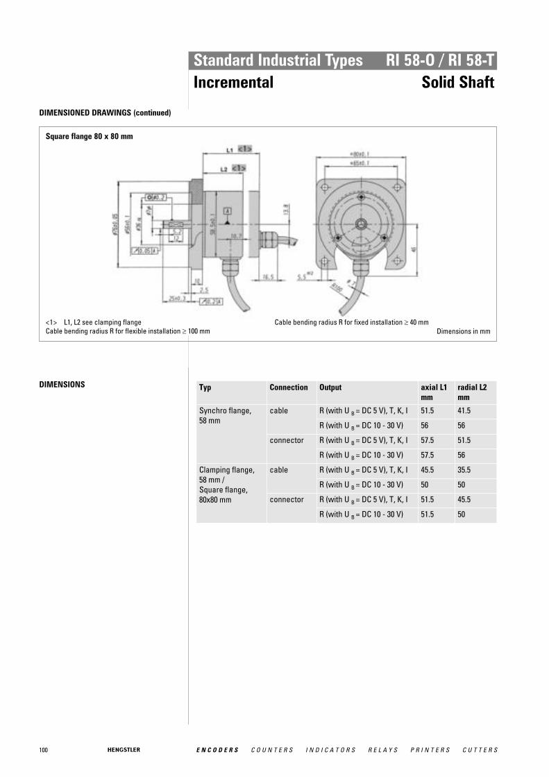
100 E N C O D E R S C O U N T E R S I N D I C A T O R S R E L A Y S P R I N T E R S C U T T E R S
Standard Industrial Types RI 58-O / RI 58-TIncremental Solid Shaft
DIMENSIONED DRAWINGS (continued)
Square flange 80 x 80 mm
<1> L1, L2 see clamping flangeCable bending radius R for flexible installation ≥ 100 mm
Cable bending radius R for fixed installation ≥ 40 mmDimensions in mm
DIMENSIONS Typ Connection Output axial L1 mm
radial L2 mm
Synchro flange, 58 mm
cable R (with U B = DC 5 V), T, K, I 51.5 41.5
R (with U B = DC 10 - 30 V) 56 56
connector R (with U B = DC 5 V), T, K, I 57.5 51.5
R (with U B = DC 10 - 30 V) 57.5 56
Clamping flange, 58 mm /Square flange, 80x80 mm
cable R (with U B = DC 5 V), T, K, I 45.5 35.5
R (with U B = DC 10 - 30 V) 50 50
connector R (with U B = DC 5 V), T, K, I 51.5 45.5
R (with U B = DC 10 - 30 V) 51.5 50

101E N C O D E R S C O U N T E R S I N D I C A T O R S R E L A Y S P R I N T E R S C U T T E R S
Standard Industrial Types RI 58-O / RI 58-TIncremental Solid Shaft
STANDARD VERSIONS

102 E N C O D E R S C O U N T E R S I N D I C A T O R S R E L A Y S P R I N T E R S C U T T E R S
Standard Industrial Types RI 58-O / RI 58-TIncremental Solid Shaft
STANDARD VERSIONS (100 °C max. operating temperature)

103E N C O D E R S C O U N T E R S I N D I C A T O R S R E L A Y S P R I N T E R S C U T T E R S
Standard Industrial Types RI 58-O / RI 58-TIncremental Solid Shaft
ORDERING INFORMATION
Type Numberof pulses
Supply vol-tage 1
Flange, Protection, Shaft 2, 3 Output 4 Connection 5, 6
RI58-ORI58-T
RI 58-O:1 ... 10000RI 58-T:4 ... 2500
A DC 5 VE DC
10 - 30 V
S.41 Synchro, IP64, 6 mmS.45 Synchro, IP64, 6.35 mmS.71 Synchro, IP67, 6 mmS.75 Synchro, IP67, 6.35 mmK.42 Clamping, IP64, 10 mmK.47 Clamping, IP64, 12 mmK.43 Clamping, IP64, 7 mmK.46 Clamping, IP64, 9.52 mmK.72 Clamping, IP67, 10 mmK.76 Clamping, IP67, 9.52 mmM.46 Syn.clamping, IP64,
9.52 mmM.76 Syn.clamping, IP67,
9.52 mmQ.46 Square, IP64, 9.52 mmQ.42 Square, IP64, 10 mmQ.76 Square, IP67, 9.52 mmQ.72 Square, IP67, 10 mmG.73 Square 80x80, IP67, 7 mm
R RS422 +AlarmT RS422 +SenseK Push-pullI Push-pull
complementary
A PVC cable, axialB PVC cable, radialE TPE cable, axialF TPE cable, radialC M23 connector (Conin),
12 pole, axial, cwD M23 connector (Conin), 12 pole,
radial, cwG M23 connector (Conin), 12 pole,
axial, ccwH M23 connector (Conin), 12 pole,
radial, ccwJ M16 connector (Binder),
6 pole, radialN M16 connector (Binder),
6 pole, axialO MS connector, 10 pole (Insert
arrangement 18-1), axialK MS connector, 10 pole (Insert
arrangement 18-1), radial1 DC 10 - 30 V only with push-pull2 other flange versions can be realized by combination of clamping flange + flange adapter (see Accessories), e.g. RI58 with synchro
flange and 10 mm-shaft: version clamping flange with 10 mm-shaft + synchro flange adapter (1 522 328)3 Output code "K" and "I": short-circuit-proof4 Connection code "O", "K": according to MIL-C-5015 (only RI 58-O)5 IP67 on cover with connector only if IP67 mating connector mounted properly.6 Connection code "O", "K": according to MIL-C-5016 (only RI 58-T)
ORDERING INFORMATION Selection of cable length
Versions with cable outlet (connection A, B, E or F) are available with various lengths ofcable. To order your desired cable length, please add the respective code to the end ofyour ordering code. Further cable lengths on request.
Code Cable length
without code 1.5 m
-D0 3 m
-F0 5 m
-K0 10 m
-P0 15 m
-U0 20 m
-V0 25 m
ACCESSORIES see chapter "Accessories", starting page 322
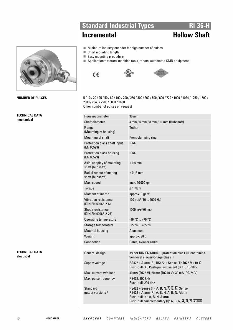
104 E N C O D E R S C O U N T E R S I N D I C A T O R S R E L A Y S P R I N T E R S C U T T E R S
Standard Industrial Types RI 36-HIncremental Hollow Shaft
� Miniature industry encoder for high number of pulses� Short mounting length� Easy mounting procedure� Applications: motors, machine tools, robots, automated SMD equipment
NUMBER OF PULSES 5 / 10 / 20 / 25 / 50 / 60 / 100 / 200 / 250 / 300 / 360 / 500 / 600 / 720 / 1000 / 1024 / 1250 / 1500 /2000 / 2048 / 2500 / 3000 / 3600 Other number of pulses on request
TECHNICAL DATA mechanical
Housing diameter 36 mm
Shaft diameter 4 mm / 6 mm / 8 mm / 10 mm (Hubshaft)
Flange (Mounting of housing)
Tether
Mounting of shaft Front clamping ring
Protection class shaft input (EN 60529)
IP64
Protection class housing (EN 60529)
IP64
Axial endplay of mounting shaft (hubshaft)
± 0.5 mm
Radial runout of mating shaft (hubshaft)
± 0.15 mm
Max. speed max. 10 000 rpm
Torque ≤ 1 Ncm
Moment of inertia approx. 3 gcm²
Vibration resistance (DIN EN 60068-2-6)
100 m/s² (10 ... 2000 Hz)
Shock resistance (DIN EN 60068-2-27)
1000 m/s² (6 ms)
Operating temperature -10 °C ... +70 °C
Storage temperature -25 °C ... +85 °C
Material housing Aluminum
Weight approx. 80 g
Connection Cable, axial or radial
TECHNICAL DATA electrical
General design as per DIN EN 61010-1, protection class III, contamina-tion level 2, overvoltage class II
Supply voltage 1 RS422 + Alarm (R), RS422 + Sense (T): DC 5 V ±10 % Push-pull (K), Push-pull antivalent (I): DC 10-30 V
Max. current w/o load 40 mA (DC 5 V), 60 mA (DC 10 V), 30 mA (DC 24 V)
Max. pulse frequency RS422: 300 kHzPush-pull: 200 kHz
Standard output versions 2
RS422 + Sense (T): A, B, N, A, B, N, SenseRS422 + Alarm (R): A, B, N, A, B, N, AlarmPush-pull (K): A, B, N, AlarmPush-pull complementary (I): A, B, N, A, B, N, Alarm

105E N C O D E R S C O U N T E R S I N D I C A T O R S R E L A Y S P R I N T E R S C U T T E R S
Standard Industrial Types RI 36-HIncremental Hollow Shaft
TECHNICAL DATA electrical (continued)
Pulse width error ± max. 25° electrical
Number of pulses 5 ... 3600
Alarm output NPN-O.C., max. 5 mA
Pulse shape Square wave
Pulse duty factor 1:11 With push-pull (K) and push-pull complementary (I): pole protection2 Output description and technical data see chapter "Technical basics"
ELECTRICAL CONNECTIONSCable PVC
Cable PVC (A, B)
Output
Colour Litze mm 2 RS422 (R, T)
push-pull (K)
push-pull complementary (I)
red 0.5 DC 5 V DC 10 - 30 V DC 10 - 30 V
yellow/red 0.14 Sense V CC Sense V CC
white 0.14 Channel A Channel A Channel A
white/brown 0.14 Channel A Channel A
green 0.14 Channel B Channel B Channel B
green/brown 0.14 Channel B Channel B
yellow 0.14 Channel N Channel N Channel N
yellow/brown 0.14 Channel N Channel N
black 0.5 GND GND GND
yellow/black 0.14 Alarm/Sense GND 1 Alarm Alarm
screen 2 screen 2 screen 2 screen 2
1 depending on ordering code 2 connected with encoder housing

106 E N C O D E R S C O U N T E R S I N D I C A T O R S R E L A Y S P R I N T E R S C U T T E R S
Standard Industrial Types RI 36-HIncremental Hollow Shaft
DIMENSIONED DRAWINGS
Torque support "J"
Dim. Hollow shaft Ø Unit
A 4 +0.01 6 +0.01 8 +0.01 10 +0.01 mm
A* 4 g7 10 g7 8 g7 10 g7 mm
B 4.8 ± 0.2 4.8 ± 0.2 4.8 ± 0.2 4.8 ± 0.2 mm
D 12 14 16 18 mm
L min 6 9 12 15 mm
L max 20 20 20 20 mm
A* = diameter of connection shaft
B = space between housing and shaft
D = diameter clamping ring
L = length of connection shaft
<1> axial<2> radial<3> Cable radial<4> Ø 6 or Ø 8Cable bending radius R for flexible installation ≥ 100 mmCable bending radius R for fixed installation ≥ 40 mmTightening torque of set screw: 15 Ncm
Dimensions in mm

107E N C O D E R S C O U N T E R S I N D I C A T O R S R E L A Y S P R I N T E R S C U T T E R S
Standard Industrial Types RI 36-HIncremental Hollow Shaft
DIMENSIONED DRAWINGS (continued)
Torque support "F"
Dim. Hollow shaft Ø Unit
A 4 +0.01 6 +0.01 8 +0.01 10 +0.01 mm
A* 4 g7 10 g7 8 g7 10 g7 mm
B 4.8 ± 0.2 4.8 ± 0.2 4.8 ± 0.2 4.8 ± 0.2 mm
D 12 14 16 18 mm
L min 6 9 12 15 mm
L max 20 20 20 20 mm
A* = diameter of connection shaft
B = space between housing and shaft
D = diameter clamping ring
L = length of connection shaft
<1> axial<2> radialCable bending radius R for flexible installation ≥ 100 mmCable bending radius R for fixed installation ≥ 40 mmTightening torque of set screw: 15 NcmThe hubshaft with tether (F) as torque supportmust be fixed by a cylindric
pin (2.4 mm ∅) at the machine side.
Dimensions in mm

108 E N C O D E R S C O U N T E R S I N D I C A T O R S R E L A Y S P R I N T E R S C U T T E R S
Standard Industrial Types RI 36-HIncremental Hollow Shaft
ORDERING INFORMATION
Type Number ofpulses
Supply voltage 1 Flange, Protection, Shaft 3, 4 Output 2 Connection
RI36-H 5 ... 3600 A DC 5 VE DC 10 - 30 V
F.30 Spring tether "F" withclamping ring front, IP64,4 mm
F.31 Spring tether "F" withclamping ring front, IP64,6 mm
F.3C Spring tether "F" withclamping ring front, IP64,8 mm
F.32 Spring tether "F" withclamping ring front, IP64,10 mm
J.30 Spring tether "J" withclamping ring front, IP64,4 mm
J.31 Spring tether "J" withclamping ring front, IP64,6 mm
J.3C Spring tether "J" withclamping ring front, IP64,8 mm
J.32 Spring tether "J" withclamping ring front, IP64,10 mm
R RS422 +AlarmT RS422 +SenseK Push-pullI Push-pull
complementary
A Cable, axialB Cable, radialE-I M23 connector
(Conin) at 1 mTPE cable, cw
E-D M23 connector(Conin) at 1 mTPE cable, ccw
1 DC 10 - 30 V only with push-pull2 Output code "K" and "I": short-circuit-proof3 Fixing of hubshaft with tether by cylindrical pin4 Fixing of hubshaft with tether by oblong hole
ORDERING INFORMATION Selection of cable length
Versions with cable outlet (connection A, B, E or F) are available with various lengths ofcable. To order your desired cable length, please add the respective code to the end ofyour ordering code. Further cable lengths on request.
Code Cable length
without code 1.5 m
-D0 3 m
-F0 5 m
-K0 10 m
-P0 15 m
-U0 20 m
-V0 25 m
ACCESSORIES see chapter "Accessories", starting page 322
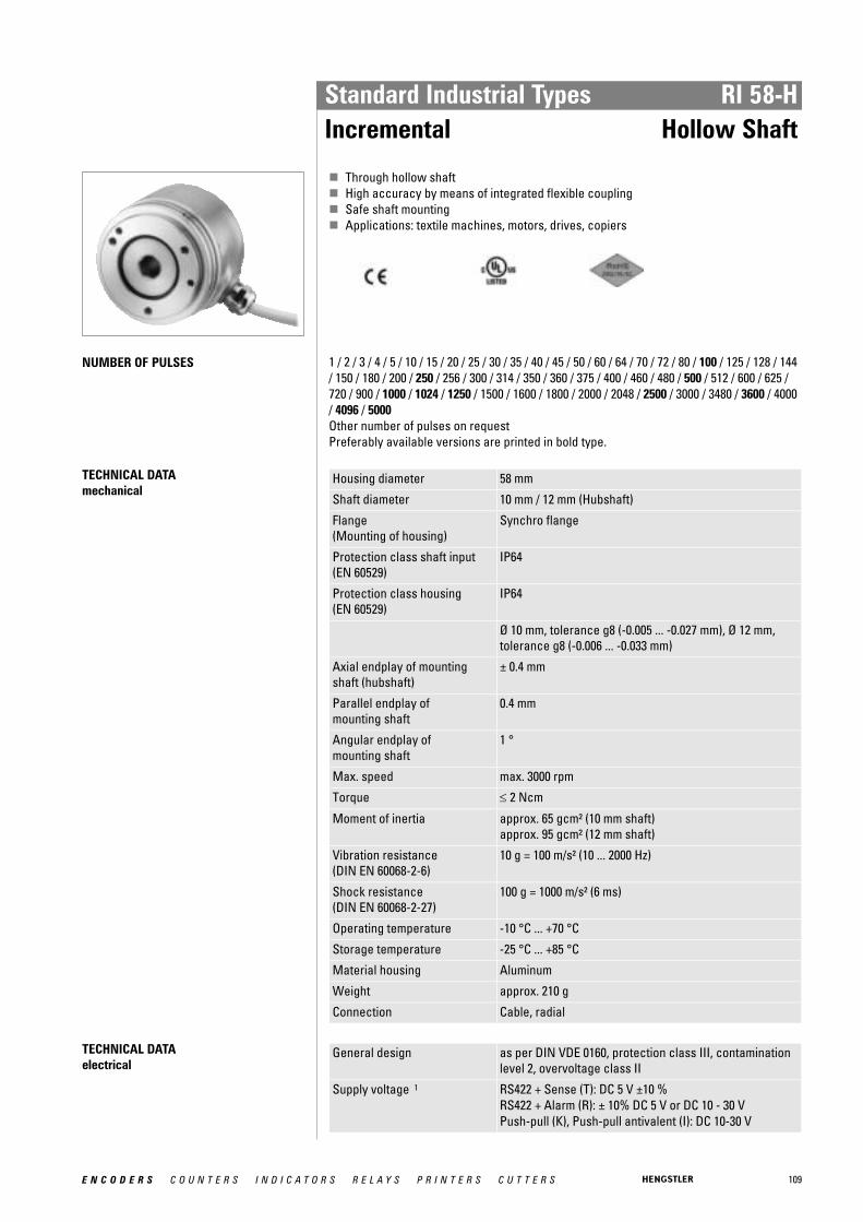
109E N C O D E R S C O U N T E R S I N D I C A T O R S R E L A Y S P R I N T E R S C U T T E R S
Standard Industrial Types RI 58-HIncremental Hollow Shaft
� Through hollow shaft� High accuracy by means of integrated flexible coupling� Safe shaft mounting� Applications: textile machines, motors, drives, copiers
NUMBER OF PULSES 1 / 2 / 3 / 4 / 5 / 10 / 15 / 20 / 25 / 30 / 35 / 40 / 45 / 50 / 60 / 64 / 70 / 72 / 80 / 100 / 125 / 128 / 144/ 150 / 180 / 200 / 250 / 256 / 300 / 314 / 350 / 360 / 375 / 400 / 460 / 480 / 500 / 512 / 600 / 625 /720 / 900 / 1000 / 1024 / 1250 / 1500 / 1600 / 1800 / 2000 / 2048 / 2500 / 3000 / 3480 / 3600 / 4000/ 4096 / 5000 Other number of pulses on request Preferably available versions are printed in bold type.
TECHNICAL DATA mechanical
Housing diameter 58 mm
Shaft diameter 10 mm / 12 mm (Hubshaft)
Flange (Mounting of housing)
Synchro flange
Protection class shaft input (EN 60529)
IP64
Protection class housing (EN 60529)
IP64
Ø 10 mm, tolerance g8 (-0.005 ... -0.027 mm), Ø 12 mm,tolerance g8 (-0.006 ... -0.033 mm)
Axial endplay of mounting shaft (hubshaft)
± 0.4 mm
Parallel endplay of mounting shaft
0.4 mm
Angular endplay of mounting shaft
1 °
Max. speed max. 3000 rpm
Torque ≤ 2 Ncm
Moment of inertia approx. 65 gcm² (10 mm shaft)approx. 95 gcm² (12 mm shaft)
Vibration resistance (DIN EN 60068-2-6)
10 g = 100 m/s² (10 ... 2000 Hz)
Shock resistance (DIN EN 60068-2-27)
100 g = 1000 m/s² (6 ms)
Operating temperature -10 °C ... +70 °C
Storage temperature -25 °C ... +85 °C
Material housing Aluminum
Weight approx. 210 g
Connection Cable, radial
TECHNICAL DATA electrical
General design as per DIN VDE 0160, protection class III, contaminationlevel 2, overvoltage class II
Supply voltage 1 RS422 + Sense (T): DC 5 V ±10 % RS422 + Alarm (R): ± 10% DC 5 V or DC 10 - 30 VPush-pull (K), Push-pull antivalent (I): DC 10-30 V
110 E N C O D E R S C O U N T E R S I N D I C A T O R S R E L A Y S P R I N T E R S C U T T E R S
Standard Industrial Types RI 58-HIncremental Hollow Shaft
TECHNICAL DATA electrical (continued)
Max. current w/o load 40 mA (DC 5 V), 60 mA (DC 10 V), 30 mA (DC 24 V)
Max. pulse frequency RS422: 300 kHzPush-pull: 200 kHz
Standard output versions 2
RS422 + Alarm (R): A, B, N, A, B, N, AlarmRS422 + Sense (T): A, B, N, A, B, N, SensePush-pull (K): A, B, N, AlarmPush-pull complementary (I): A, B, N, A, B, N, Alarm
Pulse width error ± max. 25° electrical
Number of pulses 1 ... 5000
Pulse shape Square wave
Pulse duty factor 1:11 Pole protection with supply voltage DC 10 - 30 V2 Output description and technical data see chapter "Technical basics"
ELECTRICAL CONNECTIONSCable PVC
Connectingcable Colour
Lead ∅∅ Output RS422 T and R
push-pull K and I
red 0.5 mm 2 DC 5/10 - 30 V DC 10 - 30 V
red/yellow 0.14 mm 2 Sense VCC Sense VCC
white 0.14 mm 2 Channel A Channel A
white 0.14 mm 2 Channel A Channel A1
green/brown 0.14 mm 2 Channel B Channel B
green/brown 0.14 mm 2 Channel B Channel B 1
yellow 0.14 mm 2 Channel N Channel N
yellow/brown 0.14 mm 2 Channel N Channel N 1
black 0.5mm 2 GND GND
black/yellow 0.14 mm 2 Alarm/Sense GND 2 Alarm
screen 3 screen 3 screen 3
1 only push-pull complementary (I) 2 depending on ordering code 3 connected with encoder housing

111E N C O D E R S C O U N T E R S I N D I C A T O R S R E L A Y S P R I N T E R S C U T T E R S
Standard Industrial Types RI 58-HIncremental Hollow Shaft
DIMENSIONED DRAWINGS
Synchro flange
Required dimension of mounting shaft (g8)
Hollow shaft Ø (A)
B Unit
-0.005 ... -0.027 10 * 28 mm
-0.006 ... -0.033 12 * 33 mm
* Tolerance H7 = 0 ... +0.018 mm
<1> value in brackets with version DC 10 - 30 V, RS422<2> mounting thread M4x5Cable bending radius R for flexible installation ≥ 100 mmCable bending radius R for fixed installation ≥ 40 mm
Dimensions in mm
ORDERING INFORMATION
Type Number ofpulses
Supply voltage1, 2
Flange, Protection, Shaft Output Connection
RI58-H 1 ... 5000 A DC 5 VE DC 10 - 30 V
S.42 Synchro, IP64, 10 mmS.47 Synchro, IP64, 12 mm
R RS422 +AlarmT RS422 +SenseK Push-pullI Push-pull
complementary
B PVC cable, radial
1 DC 5 V: only with output "T", "R" available2 DC 10 - 30 V: only with output "K", "I", "R" available
112 E N C O D E R S C O U N T E R S I N D I C A T O R S R E L A Y S P R I N T E R S C U T T E R S
Standard Industrial Types RI 58-HIncremental Hollow Shaft
ORDERING INFORMATION Selection of cable length
Versions with cable outlet (connection A, B, E or F) are available with various lengths ofcable. To order your desired cable length, please add the respective code to the end ofyour ordering code. Further cable lengths on request.
Code Cable length
without code 1.5 m
-D0 3 m
-F0 5 m
-K0 10 m
-P0 15 m
-U0 20 m
-V0 25 m
ACCESSORIES see chapter "Accessories", starting page 322
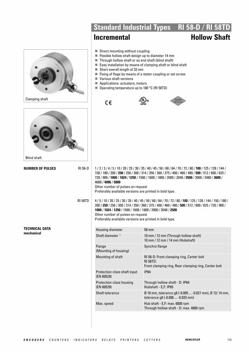
113E N C O D E R S C O U N T E R S I N D I C A T O R S R E L A Y S P R I N T E R S C U T T E R S
Standard Industrial Types RI 58-D / RI 58TDIncremental Hollow Shaft
Clamping shaft
Blind shaft
� Direct mounting without coupling� Flexible hollow shaft design up to diameter 14 mm� Through hollow shaft or as end shaft (blind shaft)� Easy installation by means of clamping shaft or blind shaft� Short overall length of 33 mm� Fixing of flage by means of a stator coupling or set screw� Various shaft versions� Applications: actuators, motors� Operating temperature up to 100 °C (RI 58TD)
NUMBER OF PULSES RI 58-D 1 / 2 / 3 / 4 / 5 / 10 / 20 / 25 / 30 / 35 / 40 / 45 / 50 / 60 / 64 / 70 / 72 / 80 / 100 / 125 / 128 / 144 /150 / 180 / 200 / 250 / 256 / 300 / 314 / 350 / 360 / 375 / 400 / 460 / 480 / 500 / 512 / 600 / 625 /720 / 900 / 1000 / 1024 / 1250 / 1500 / 1600 / 1800 / 2000 / 2048 / 2500 / 3000 / 3480 / 3600 / 4000 / 4096 / 5000 Other number of pulses on request Preferably available versions are printed in bold type.
RI 58TD 4 / 5 / 10 / 20 / 25 / 30 / 35 / 40 / 45 / 50 / 60 / 64 / 70 / 72 / 80 / 100 / 125 / 128 / 144 / 150 / 180 /200 / 250 / 256 / 300 / 314 / 350 / 360 / 375 / 400 / 460 / 480 / 500 / 512 / 600 / 625 / 720 / 900 /1000 / 1024 / 1250 / 1500 / 1600 / 1800 / 2000 / 2048 / 2500 Other number of pulses on request Preferably available versions are printed in bold type.
TECHNICAL DATA mechanical
Housing diameter 58 mm
Shaft diameter 1 10 mm / 12 mm (Through hollow shaft)10 mm / 12 mm / 14 mm (Hubshaft)
Flange (Mounting of housing)
Synchro flange
Mounting of shaft RI 58-D: Front clamping ring, Center boltRI 58TD: Front clamping ring, Rear clamping ring, Center bolt
Protection class shaft input (EN 60529)
IP64
Protection class housing (EN 60529)
Through hollow shaft - D: IP64Hubshaft - E,F: IP65
Shaft tolerance Ø 10 mm, tolerance g8 (-0.005 ... -0.027 mm), Ø 12/ 14 mm,tolerance g8 (-0.006 ... -0.033 mm)
Max. speed Hub shaft - E,F: max. 6000 rpmThrough hollow shaft - D: max. 4000 rpm
114 E N C O D E R S C O U N T E R S I N D I C A T O R S R E L A Y S P R I N T E R S C U T T E R S
Standard Industrial Types RI 58-D / RI 58TDIncremental Hollow Shaft
TECHNICAL DATA mechanical (continued)
Torque ≤ 1 Ncm (Hub shaft - E,F)≤ 2 Ncm (Through hollow shaft - D)
Moment of inertia approx. 35 gcm² (Hub shaft with clamping ring front - F)approx. 20 gcm² (Hub shaft, mountig with set screw - E)approx. 60 gcm² (Through hollow shaft with clamping ringfront - D)
Vibration resistance (DIN EN 60068-2-6)
10 g = 100 m/s² (10 ... 2000 Hz)
Shock resistance (DIN EN 60068-2-27)
100 g = 1000 m/s² (6 ms)
Operating temperature RI 58-D: -10 °C ... +70 °CRI 58TD: -25 °C ... +100 °C
Storage temperature -25 °C ... +85 °C
Material housing Aluminum
Weight approx. 170 g with hubshaft (E,F), approx. 190 g withtrough hollow shaft (D)
Connection 2 Cable, axial or radialM23 connector (Conin), radial
1 Other shaft diameters on request2 Standard cable length: 1.5 m cable, other cable length on request (only RI 58TD)
TECHNICAL DATA electrical
General design as per DIN VDE 0160, protection class III, contaminationlevel 2, overvoltage class II
Supply voltage 1 RS422 + Sense (T): DC 5 V ±10 % RS422 + Alarm (R): ± 10% DC 5 V or DC 10 - 30 VPush-pull (K), Push-pull antivalent (I): DC 10-30 V
Max. current w/o load 40 mA (DC 5 V), 60 mA (DC 10 V), 30 mA (DC 24 V)
Max. pulse frequency RS422: 300 kHzPush-pull: 200 kHz
Standard output versions 2
RS422 + Alarm (R): A, B, N, A, B, N, AlarmRS422 + Sense (T): A, B, N, A, B, N, SensePush-pull (K): A, B, N, AlarmPush-pull complementary (I): A, B, N, A, B, N, Alarm
Pulse width error ± max. 25° electrical
Number of pulses 1 ... 5000
Alarm output NPN-O.C., max. 5 mA
Pulse shape Square wave
Pulse duty factor 1:11 With push-pull (K): pole protection2 Output description and technical data see chapter "Technical basics"
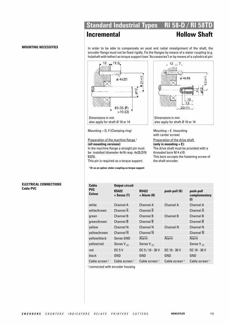
115E N C O D E R S C O U N T E R S I N D I C A T O R S R E L A Y S P R I N T E R S C U T T E R S
Standard Industrial Types RI 58-D / RI 58TDIncremental Hollow Shaft
MOUNTING NECESSITIES In order to be able to compensate an axial and radial misalignment of the shaft, the encoder flange must not be fixed rigidly. Fix the flanges by means of a stator coupling (e.g.hubshaft with tether) as torque support (see "Accessories") or by means of a cylindrical pin:
Dimensions in mm also apply for shaft-Ø 10 or 14
Dimensions in mm also apply for shaft-Ø 10 or 14
Mounting = D, F (Clamping ring)
Preparation of the machine flange 1
(all mounting versions): In the machine flange a straight pin mustbe installed (diameter 4x16 resp. 4x20,DIN6325). This pin is required as a torque support.
Mounting = E (mounting with center screw) Preparation of the drive shaft (only in mounting = E): The drive shaft must be provided with athreaded bore M 4 x10: This bore accepts the fastening screw of the shaft encoder.
1 Or as an option: stator coupling as torque support
ELECTRICAL CONNECTIONSCable PVC
Cable PVC Colour
Output circuit
RS422 + Sense (T)
RS422 + Alarm (R)
push-pull (K) push-pull complementary(I)
white Channel A Channel A Channel A Channel A
white/brown Channel A Channel A Channel A
green Channel B Channel B Channel B Channel B
green/brown Channel B Channel B Channel B
yellow Channel N Channel N Channel N Channel N
yellow/brown Channel N Channel N Channel N
yellow/black Sense GND Alarm Alarm Alarm
yellow/red Sense V CC Sense V CC Sense V CC
red DC 5 V DC 5 / 10 - 30 V DC 10 - 30 V DC 10 - 30 V
black GND GND GND GND
Cable screen 1 Cable screen 1 Cable screen 1 Cable screen 1 Cable screen 1
1 connected with encoder housing
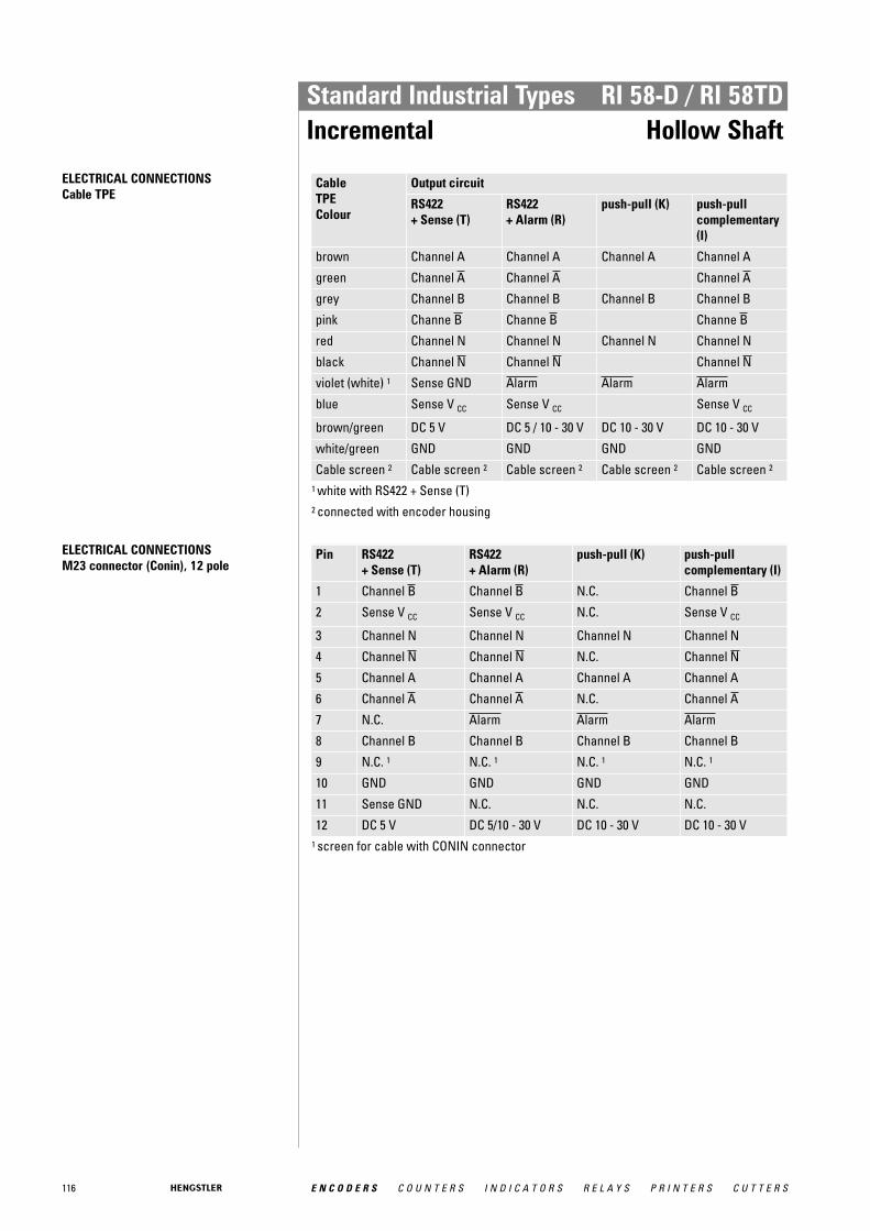
116 E N C O D E R S C O U N T E R S I N D I C A T O R S R E L A Y S P R I N T E R S C U T T E R S
Standard Industrial Types RI 58-D / RI 58TDIncremental Hollow Shaft
ELECTRICAL CONNECTIONSCable TPE
Cable TPE Colour
Output circuit
RS422 + Sense (T)
RS422 + Alarm (R)
push-pull (K) push-pull complementary(I)
brown Channel A Channel A Channel A Channel A
green Channel A Channel A Channel A
grey Channel B Channel B Channel B Channel B
pink Channe B Channe B Channe B
red Channel N Channel N Channel N Channel N
black Channel N Channel N Channel N
violet (white) 1 Sense GND Alarm Alarm Alarm
blue Sense V CC Sense V CC Sense V CC
brown/green DC 5 V DC 5 / 10 - 30 V DC 10 - 30 V DC 10 - 30 V
white/green GND GND GND GND
Cable screen 2 Cable screen 2 Cable screen 2 Cable screen 2 Cable screen 2
1 white with RS422 + Sense (T) 2 connected with encoder housing
ELECTRICAL CONNECTIONSM23 connector (Conin), 12 pole
Pin RS422 + Sense (T)
RS422 + Alarm (R)
push-pull (K) push-pull complementary (I)
1 Channel B Channel B N.C. Channel B
2 Sense V CC Sense V CC N.C. Sense V CC
3 Channel N Channel N Channel N Channel N
4 Channel N Channel N N.C. Channel N
5 Channel A Channel A Channel A Channel A
6 Channel A Channel A N.C. Channel A
7 N.C. Alarm Alarm Alarm
8 Channel B Channel B Channel B Channel B
9 N.C. 1 N.C. 1 N.C. 1 N.C. 1
10 GND GND GND GND
11 Sense GND N.C. N.C. N.C.
12 DC 5 V DC 5/10 - 30 V DC 10 - 30 V DC 10 - 30 V 1 screen for cable with CONIN connector

117E N C O D E R S C O U N T E R S I N D I C A T O R S R E L A Y S P R I N T E R S C U T T E R S
Standard Industrial Types RI 58-D / RI 58TDIncremental Hollow Shaft
DIMENSIONED DRAWINGS
Mounting F: Hubshaft with clamping ring front
Dim. Hollow shaft Ø Unit
A 10 H7 12 H7 14 H7 mm
A* 10 g8 12 g8 14 g8 mm
B 26 28 30 mm
T 33.5 33.5 22.5 mm
A* = diameter of connection shaft
<1> View turned 60°<2> mounting thread M4x5<3> value in brackets with version DC 10 - 30 V, RS422Cable bending radius R for flexible installation ≥ 100 mmCable bending radius R for fixed installation ≥ 40 mm
Dimensions in mm
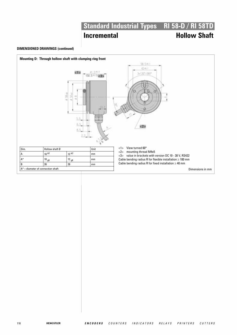
118 E N C O D E R S C O U N T E R S I N D I C A T O R S R E L A Y S P R I N T E R S C U T T E R S
Standard Industrial Types RI 58-D / RI 58TDIncremental Hollow Shaft
DIMENSIONED DRAWINGS (continued)
Mounting D: Through hollow shaft with clamping ring front
Dim. Hollow shaft Ø Unit
A 10 H7 12 H7 mm
A* 10 g8 12 g8 mm
B 26 28 mm
A* = diameter of connection shaft
<1> View turned 60°<2> mounting thread M4x5<3> value in brackets with version DC 10 - 30 V, RS422Cable bending radius R for flexible installation ≥ 100 mmCable bending radius R for fixed installation ≥ 40 mm
Dimensions in mm
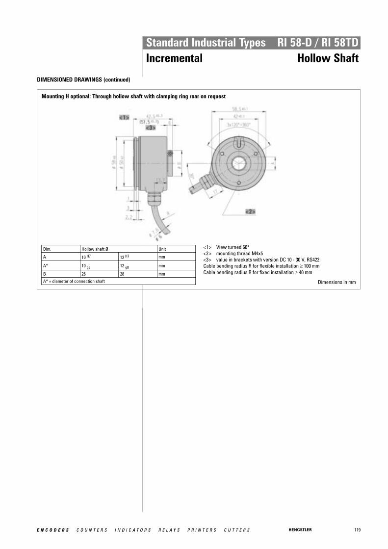
119E N C O D E R S C O U N T E R S I N D I C A T O R S R E L A Y S P R I N T E R S C U T T E R S
Standard Industrial Types RI 58-D / RI 58TDIncremental Hollow Shaft
DIMENSIONED DRAWINGS (continued)
Mounting H optional: Through hollow shaft with clamping ring rear on request
Dim. Hollow shaft Ø Unit
A 10 H7 12 H7 mm
A* 10 g8 12 g8 mm
B 26 28 mm
A* = diameter of connection shaft
<1> View turned 60°<2> mounting thread M4x5<3> value in brackets with version DC 10 - 30 V, RS422Cable bending radius R for flexible installation ≥ 100 mmCable bending radius R for fixed installation ≥ 40 mm
Dimensions in mm

120 E N C O D E R S C O U N T E R S I N D I C A T O R S R E L A Y S P R I N T E R S C U T T E R S
Standard Industrial Types RI 58-D / RI 58TDIncremental Hollow Shaft
DIMENSIONED DRAWINGS (continued)
Mounting E: Hubshaft, mounting with center screw
Dim. Hollow shaft Ø Unit
A 10 H7 12 H7 14 H7 mm
A* 10 g8 12 g8 14 g8 mm
C 15 15 17 mm
T 18±0.5 18±0.5 18±0.5 mm A* = diameter of connection shaft T = length of custom shaft in encoder
<1> View turned 60°<2> mounting thread M4x5<3> value in brackets with version DC 10 - 30 V, RS422Cable bending radius R for flexible installation ≥ 100 mmCable bending radius R for fixed installation ≥ 40 mm
Dimensions in mm
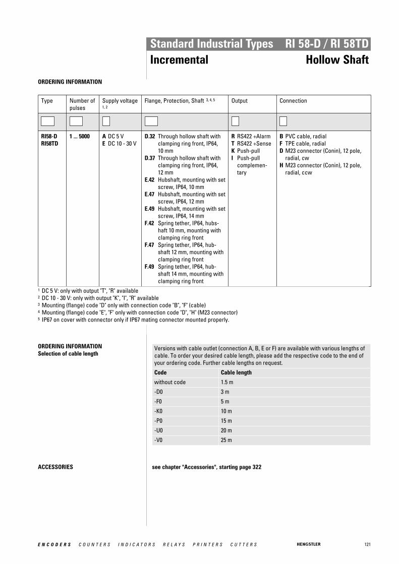
121E N C O D E R S C O U N T E R S I N D I C A T O R S R E L A Y S P R I N T E R S C U T T E R S
Standard Industrial Types RI 58-D / RI 58TDIncremental Hollow Shaft
ORDERING INFORMATION
Type Number ofpulses
Supply voltage1, 2
Flange, Protection, Shaft 3, 4, 5 Output Connection
RI58-DRI58TD
1 ... 5000 A DC 5 VE DC 10 - 30 V
D.32 Through hollow shaft withclamping ring front, IP64, 10 mm
D.37 Through hollow shaft withclamping ring front, IP64, 12 mm
E.42 Hubshaft, mounting with setscrew, IP64, 10 mm
E.47 Hubshaft, mounting with setscrew, IP64, 12 mm
E.49 Hubshaft, mounting with setscrew, IP64, 14 mm
F.42 Spring tether, IP64, hubs-haft 10 mm, mounting withclamping ring front
F.47 Spring tether, IP64, hub-shaft 12 mm, mounting withclamping ring front
F.49 Spring tether, IP64, hub-shaft 14 mm, mounting withclamping ring front
R RS422 +AlarmT RS422 +SenseK Push-pullI Push-pull
complemen-tary
B PVC cable, radialF TPE cable, radialD M23 connector (Conin), 12 pole,
radial, cwH M23 connector (Conin), 12 pole,
radial, ccw
1 DC 5 V: only with output "T", "R" available2 DC 10 - 30 V: only with output "K", "I", "R" available3 Mounting (flange) code "D" only with connection code "B", "F" (cable)4 Mounting (flange) code "E", "F" only with connection code "D", "H" (M23 connector)5 IP67 on cover with connector only if IP67 mating connector mounted properly.
ORDERING INFORMATION Selection of cable length
Versions with cable outlet (connection A, B, E or F) are available with various lengths ofcable. To order your desired cable length, please add the respective code to the end ofyour ordering code. Further cable lengths on request.
Code Cable length
without code 1.5 m
-D0 3 m
-F0 5 m
-K0 10 m
-P0 15 m
-U0 20 m
-V0 25 m
ACCESSORIES see chapter "Accessories", starting page 322

122 E N C O D E R S C O U N T E R S I N D I C A T O R S R E L A Y S P R I N T E R S C U T T E R S
Standard Industrial Types RI 58-G / RI 58TGIncremental Hollow Shaft
Clamping shaft
� Direct mounting without coupling� Through hollow shaft Ø 14 mm and 15 mm� Easy installation by means of clamping ring� Fixing of flage by means of a stator coupling or set screw� Applications: actuators, motors
NUMBER OF PULSES RI 58-G 50 / 360 / 500 / 1000 / 1024 / 2000 / 2048 / 2500 / 3600 / 4096 / 5000
NUMBER OF PULSES RI 58TG 50 / 360 / 500 / 1000 / 1024 / 2000 / 2048 / 2500
TECHNICAL DATA mechanical
Housing diameter 58 mm
Shaft diameter 14 mm / 15 mm (Through hollow shaft)
Flange (Mounting of housing)
Synchro flange
Mounting of shaft Front clamping ring, Rear clamping ring
Protection class shaft input (EN 60529)
IP64
Protection class housing (EN 60529)
IP64
Shaft tolerance Ø 14/ 15 mm, tolerance g8
Max. speed max. 4000 rpm
Torque ≤ 2 Ncm
Moment of inertia approx. 60 gcm²
Vibration resistance (DIN EN 60068-2-6)
10 g = 100 m/s² (10 ... 2000 Hz)
Shock resistance (DIN EN 60068-2-27)
100 g = 1000 m/s² (6 ms)
Operating temperature RI 58-G: -10 °C ... +70 °CRI 58TG: -10 °C ... +100 °C
Storage temperature -25 °C ... +85 °C
Material housing Aluminum
Weight approx. 210 g
Connection Cable, radial
TECHNICAL DATA electrical
General design as per DIN VDE 0160, protection class III, contaminationlevel 2, overvoltage class II
Supply voltage 1 RS422 + Sense (T): DC 5 V ±10 % RS422 + Alarm (R): ± 10% DC 5 V or DC 10 - 30 VPush-pull (K), Push-pull antivalent (I): DC 10-30 V
Max. current w/o load 40 mA (DC 5 V), 60 mA (DC 10 V), 30 mA (DC 24 V)
Max. pulse frequency RS422: 300 kHzPush-pull: 200 kHz
Standard output versions 2
RS422 + Alarm (R): A, B, N, A, B, N, AlarmRS422 + Sense (T): A, B, N, A, B, N, SensePush-pull (K): A, B, N, AlarmPush-pull complementary (I): A, B, N, A, B, N, Alarm

123E N C O D E R S C O U N T E R S I N D I C A T O R S R E L A Y S P R I N T E R S C U T T E R S
Standard Industrial Types RI 58-G / RI 58TGIncremental Hollow Shaft
TECHNICAL DATA electrical (continued)
Pulse width error ± max. 25° electrical
Number of pulses 50 ... 2500
Alarm output NPN-O.C., max. 5 mA
Pulse shape Square wave
Pulse duty factor 1:11 With push-pull (K): pole protection2 Output description and technical data see chapter "Technical basics"
MOUNTING NECESSITIES In order to be able to compensate an axial and radial misalignment of the shaft, the encoder flange must not be fixed rigidly. Fix the flanges by means of a stator coupling (e.g.hubshaft with tether) as torque support (see "Accessories") or by means of a cylindrical pin:
Dimensions in mm also apply for shaft-Ø 10 or 14
Dimensions in mm also apply for shaft-Ø 10 or 14
Mounting = D, F (Clamping ring)
Preparation of the machine flange 1
(all mounting versions): In the machine flange a straight pin mustbe installed (diameter 4x16 resp. 4x20,DIN6325). This pin is required as a torque support.
Mounting = E (mounting with center screw) Preparation of the drive shaft (only in mounting = E): The drive shaft must be provided with athreaded bore M 4 x10: This bore accepts the fastening screw of the shaft encoder.
1 Or as an option: stator coupling as torque support

124 E N C O D E R S C O U N T E R S I N D I C A T O R S R E L A Y S P R I N T E R S C U T T E R S
Standard Industrial Types RI 58-G / RI 58TGIncremental Hollow Shaft
ELECTRICAL CONNECTIONSCable PVC
Cable PVC Colour
Output circuit
RS422 + Sense (T)
RS422 + Alarm (R)
push-pull (K) push-pull complementary(I)
white Channel A Channel A Channel A Channel A
white/brown Channel A Channel A Channel A
green Channel B Channel B Channel B Channel B
green/brown Channel B Channel B Channel B
yellow Channel N Channel N Channel N Channel N
yellow/brown Channel N Channel N Channel N
yellow/black Sense GND Alarm Alarm Alarm
yellow/red Sense V CC Sense V CC Sense V CC
red DC 5 V DC 5 / 10 - 30 V DC 10 - 30 V DC 10 - 30 V
black GND GND GND GND
Cable screen 1 Cable screen 1 Cable screen 1 Cable screen 1 Cable screen 1
1 connected with encoder housing
ELECTRICAL CONNECTIONSCable TPE
Cable TPE Colour
Output circuit
RS422 + Sense (T)
RS422 + Alarm (R)
push-pull (K) push-pull complementary(I)
brown Channel A Channel A Channel A Channel A
green Channel A Channel A Channel A
grey Channel B Channel B Channel B Channel B
pink Channe B Channe B Channe B
red Channel N Channel N Channel N Channel N
black Channel N Channel N Channel N
violet (white) 1 Sense GND Alarm Alarm Alarm
blue Sense V CC Sense V CC Sense V CC
brown/green DC 5 V DC 5 / 10 - 30 V DC 10 - 30 V DC 10 - 30 V
white/green GND GND GND GND
Cable screen 2 Cable screen 2 Cable screen 2 Cable screen 2 Cable screen 2
1 white with RS422 + Sense (T) 2 connected with encoder housing
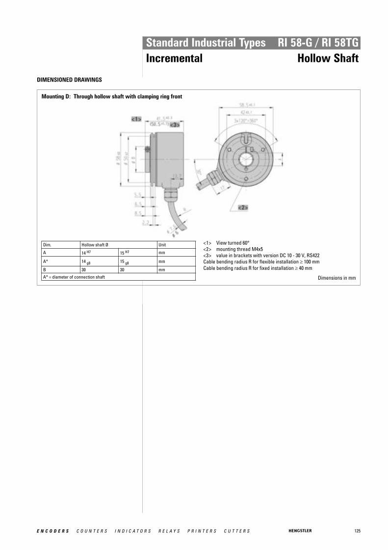
125E N C O D E R S C O U N T E R S I N D I C A T O R S R E L A Y S P R I N T E R S C U T T E R S
Standard Industrial Types RI 58-G / RI 58TGIncremental Hollow Shaft
DIMENSIONED DRAWINGS
Mounting D: Through hollow shaft with clamping ring front
Dim. Hollow shaft Ø Unit
A 14 H7 15 H7 mm
A* 14 g8 15 g8 mm
B 30 30 mm
A* = diameter of connection shaft
<1> View turned 60°<2> mounting thread M4x5<3> value in brackets with version DC 10 - 30 V, RS422Cable bending radius R for flexible installation ≥ 100 mmCable bending radius R for fixed installation ≥ 40 mm
Dimensions in mm

126 E N C O D E R S C O U N T E R S I N D I C A T O R S R E L A Y S P R I N T E R S C U T T E R S
Standard Industrial Types RI 58-G / RI 58TGIncremental Hollow Shaft
DIMENSIONED DRAWINGS (continued)
Mounting H optional: Through hollow shaft with clamping ring rear on request
Dim. Hollow shaft Ø Unit
A 14 H7 15 H7 mm
A* 14 g8 15 g8 mm
B 30 30 mm
A* = diameter of connection shaft
<1> View turned 60°<2> mounting thread M4x5<3> value in brackets with version DC 10 - 30 V, RS422Cable bending radius R for flexible installation ≥ 100 mmCable bending radius R for fixed installation ≥ 40 mm
Dimensions in mm
ORDERING INFORMATION
Type Number ofpulses
Supply voltage1, 2
Flange, Protection, Shaft 3 Output Connection
RI58-GRI58TG
RI 58-G:50 ...2500
RI 58TG:50 ...5000
A DC 5 VE DC 10 - 30 V
D.39 Through hollow shaft withclamping ring front, IP64, 14 mm
D.3D Through hollow shaft withclamping ring front, IP64, 15 mm
H.39 Through hollow shaft withclamping ring rear, IP64, 14 mm
H.3D Through hollow shaft withclamping ring rear, IP64, 15 mm
R RS422 +Alarm (RI 58-G)
T RS422 +SenseK Push-pullI Push-pull complemen-
taryR RS422 +Alarm +Sense
(RI 58TG)
B PVC cable, radialF TPE cable, radialD M23 connector (Conin),
12 pole, radial, cw (RI 58-G)
H M23 connector (Conin),12 pole, radial, ccw (RI 58-G)
1 DC 5 V: only with output "T", "R" available2 DC 10 - 30 V: only with output "K", "I", "R" available3 IP67 on cover with connector only if IP67 mating connector mounted properly.

127E N C O D E R S C O U N T E R S I N D I C A T O R S R E L A Y S P R I N T E R S C U T T E R S
Standard Industrial Types RI 58-G / RI 58TGIncremental Hollow Shaft
ORDERING INFORMATION Selection of cable length
Versions with cable outlet (connection A, B, E or F) are available with various lengths ofcable. To order your desired cable length, please add the respective code to the end ofyour ordering code. Further cable lengths on request.
Code Cable length
without code 1.5 m
-D0 3 m
-F0 5 m
-K0 10 m
-P0 15 m
-U0 20 m
-V0 25 m
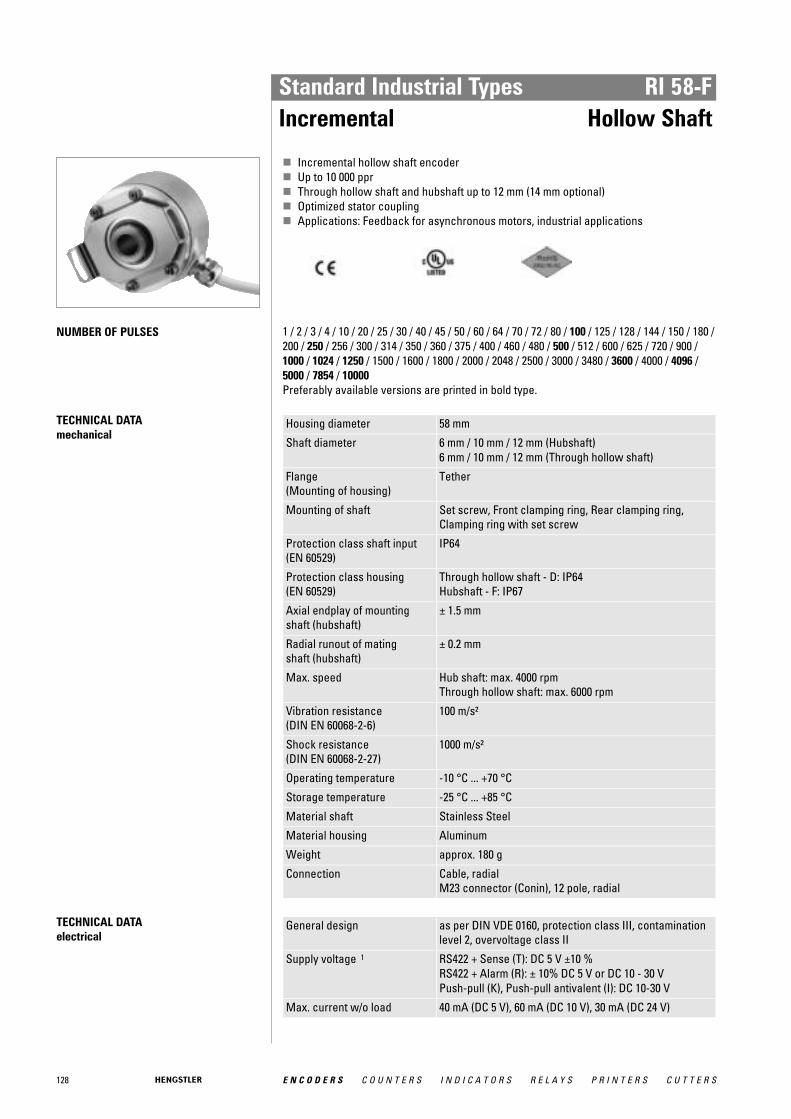
128 E N C O D E R S C O U N T E R S I N D I C A T O R S R E L A Y S P R I N T E R S C U T T E R S
Standard Industrial Types RI 58-FIncremental Hollow Shaft
� Incremental hollow shaft encoder� Up to 10 000 ppr� Through hollow shaft and hubshaft up to 12 mm (14 mm optional)� Optimized stator coupling� Applications: Feedback for asynchronous motors, industrial applications
NUMBER OF PULSES 1 / 2 / 3 / 4 / 10 / 20 / 25 / 30 / 40 / 45 / 50 / 60 / 64 / 70 / 72 / 80 / 100 / 125 / 128 / 144 / 150 / 180 /200 / 250 / 256 / 300 / 314 / 350 / 360 / 375 / 400 / 460 / 480 / 500 / 512 / 600 / 625 / 720 / 900 /1000 / 1024 / 1250 / 1500 / 1600 / 1800 / 2000 / 2048 / 2500 / 3000 / 3480 / 3600 / 4000 / 4096 /5000 / 7854 / 10000 Preferably available versions are printed in bold type.
TECHNICAL DATA mechanical
Housing diameter 58 mm
Shaft diameter 6 mm / 10 mm / 12 mm (Hubshaft)6 mm / 10 mm / 12 mm (Through hollow shaft)
Flange (Mounting of housing)
Tether
Mounting of shaft Set screw, Front clamping ring, Rear clamping ring,Clamping ring with set screw
Protection class shaft input (EN 60529)
IP64
Protection class housing (EN 60529)
Through hollow shaft - D: IP64Hubshaft - F: IP67
Axial endplay of mounting shaft (hubshaft)
± 1.5 mm
Radial runout of mating shaft (hubshaft)
± 0.2 mm
Max. speed Hub shaft: max. 4000 rpmThrough hollow shaft: max. 6000 rpm
Vibration resistance (DIN EN 60068-2-6)
100 m/s²
Shock resistance (DIN EN 60068-2-27)
1000 m/s²
Operating temperature -10 °C ... +70 °C
Storage temperature -25 °C ... +85 °C
Material shaft Stainless Steel
Material housing Aluminum
Weight approx. 180 g
Connection Cable, radialM23 connector (Conin), 12 pole, radial
TECHNICAL DATA electrical
General design as per DIN VDE 0160, protection class III, contaminationlevel 2, overvoltage class II
Supply voltage 1 RS422 + Sense (T): DC 5 V ±10 % RS422 + Alarm (R): ± 10% DC 5 V or DC 10 - 30 VPush-pull (K), Push-pull antivalent (I): DC 10-30 V
Max. current w/o load 40 mA (DC 5 V), 60 mA (DC 10 V), 30 mA (DC 24 V)

129E N C O D E R S C O U N T E R S I N D I C A T O R S R E L A Y S P R I N T E R S C U T T E R S
Standard Industrial Types RI 58-FIncremental Hollow Shaft
TECHNICAL DATA electrical (continued)
Standard output versions 2, 3
RS422 + Alarm (R): A, B, N, A, B, N, AlarmRS422 + Sense (T): A, B, N, A, B, N, SensePush-pull (K): A, B, N, AlarmPush-pull complementary (I): A, B, N, A, B, N, Alarm
Number of pulses 1 ... 10 0001 Pole protection with supply voltage DC 10 - 30 V2 Output code "K" and "I": short-circuit-proof3 Output description and technical data see chapter "Technical basics"
DIMENSIONED DRAWINGS
Hubshaft
Dim. Hollow shaft Ø Unit
A 10 -0.002/+0.008 12 -0.002/+0.008 mm
A* 10 g7 12 g7 mm
B 20 mm
L min 15.5 17.5 mm
L max 28 28 mm
A* = diameter of connection shaft
L = length of connection shaft
<1> Ø A > 10 mm<2> Ø A ≤ 10 mmCable bending radius R for flexible installation ≥ 100 mmCable bending radius R for fixed installation ≥ 40 mm
Dimensions in mm
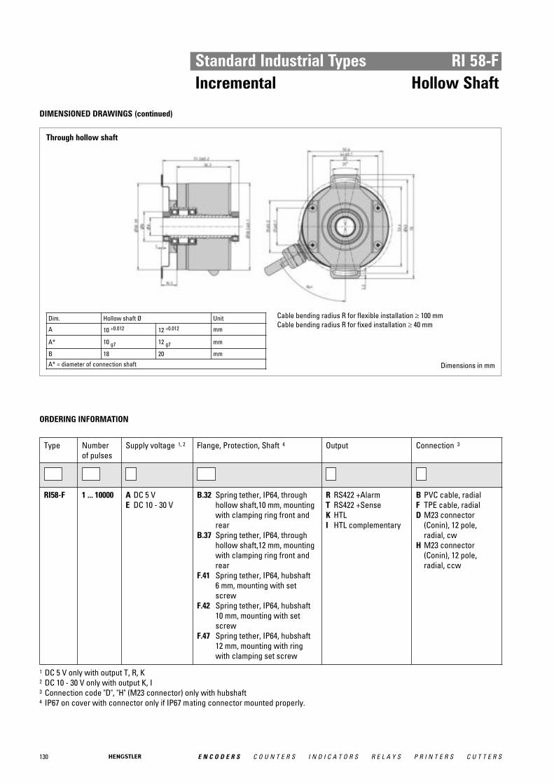
130 E N C O D E R S C O U N T E R S I N D I C A T O R S R E L A Y S P R I N T E R S C U T T E R S
Standard Industrial Types RI 58-FIncremental Hollow Shaft
DIMENSIONED DRAWINGS (continued)
Through hollow shaft
Dim. Hollow shaft Ø Unit
A 10 +0.012 12 +0.012 mm
A* 10 g7 12 g7 mm
B 18 20 mm
A* = diameter of connection shaft
Cable bending radius R for flexible installation ≥ 100 mmCable bending radius R for fixed installation ≥ 40 mm
Dimensions in mm
ORDERING INFORMATION
Type Numberof pulses
Supply voltage 1, 2 Flange, Protection, Shaft 4 Output Connection 3
RI58-F 1 ... 10000 A DC 5 VE DC 10 - 30 V
B.32 Spring tether, IP64, throughhollow shaft,10 mm, mountingwith clamping ring front andrear
B.37 Spring tether, IP64, throughhollow shaft,12 mm, mountingwith clamping ring front andrear
F.41 Spring tether, IP64, hubshaft 6 mm, mounting with setscrew
F.42 Spring tether, IP64, hubshaft10 mm, mounting with setscrew
F.47 Spring tether, IP64, hubshaft12 mm, mounting with ringwith clamping set screw
R RS422 +AlarmT RS422 +SenseK HTLI HTL complementary
B PVC cable, radialF TPE cable, radialD M23 connector
(Conin), 12 pole,radial, cw
H M23 connector(Conin), 12 pole,radial, ccw
1 DC 5 V only with output T, R, K2 DC 10 - 30 V only with output K, I3 Connection code "D", "H" (M23 connector) only with hubshaft4 IP67 on cover with connector only if IP67 mating connector mounted properly.

131E N C O D E R S C O U N T E R S I N D I C A T O R S R E L A Y S P R I N T E R S C U T T E R S
Standard Industrial Types RI 58-FIncremental Hollow Shaft
ORDERING INFORMATION Selection of cable length
Versions with cable outlet (connection A, B, E or F) are available with various lengths ofcable. To order your desired cable length, please add the respective code to the end ofyour ordering code. Further cable lengths on request.
Code Cable length
without code 1.5 m
-D0 3 m
-F0 5 m
-K0 10 m
-P0 15 m
-U0 20 m
-V0 25 m
ACCESSORIES see chapter "Accessories", starting page 322
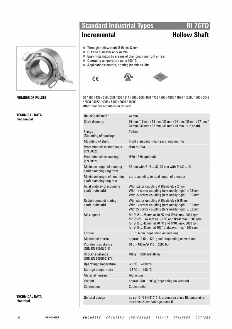
132 E N C O D E R S C O U N T E R S I N D I C A T O R S R E L A Y S P R I N T E R S C U T T E R S
Standard Industrial Types RI 76TDIncremental Hollow Shaft
� Through hollow shaft Ø 15 bis 42 mm� Outside diameter only 76 mm� Easy installation by means of clamping ring front or rear� Operating temperature up to 100 °C� Applications: motors, printing machines, lifts
NUMBER OF PULSES 50 / 100 / 128 / 250 / 256 / 300 / 314 / 360 / 500 / 600 / 720 / 900 / 1000 / 1024 / 1250 / 1500 / 2048/ 2500 / 3072 / 4096 / 5000 / 9000 / 10000 Other number of pulses on request
TECHNICAL DATA mechanical
Housing diameter 76 mm
Shaft diameter 15 mm / 16 mm / 18 mm / 20 mm / 24 mm / 25 mm / 27 mm /28 mm / 30 mm / 32 mm / 38 mm / 40 mm (Hub shaft)
Flange (Mounting of housing)
Tether
Mounting of shaft Front clamping ring, Rear clamping ring
Protection class shaft input (EN 60529)
IP40 or IP64
Protection class housing (EN 60529)
IP50 (IP65 optional)
Minimum length of mountigshaft clamping ring front
32 mm with Ø 15 ... 30, 35 mm with Ø >30 ... 42
Mimimum length of mountingshaft clamping ring rear
corresponding to total length of encoder
Axial endplay of mounting shaft (hubshaft)
With stator coupling A (flexible): ± 2 mmWith 1x stator coupling (torsionally rigid): ± 0.5 mmWith 2x stator coupling (torsionally rigid): ± 0.3 mm
Radial runout of mating shaft (hubshaft)
With stator coupling A (flexible): ± 0.15 mmWith 1x stator coupling (torsionally rigid): ± 0.3 mmWith 2x stator coupling (torsionally rigid): ± 0.2 mm
Max. speed for Ø 15 ... 25 mm at 70 °C and IP64: max. 3600 rpmfor Ø >25 ... 42 mm bei 70 °C and IP64: max. 1800 rpmfor Ø 15 ... 42 mm at 70 °C and IP40: max. 6000 rpmfor Ø 15 ... 42 mm at 100 °C always: max. 1800 rpm
Torque 3 ... 10 Ncm (depending on version)
Moment of inertia approx. 140 ... 420 gcm² (depending on version)
Vibration resistance (DIN EN 60068-2-6)
10 g = 100 m/s² (10 ... 2000 Hz)
Shock resistance (DIN EN 60068-2-27)
100 g = 1000 m/s² (6 ms)
Operating temperature -25 °C ... +100 °C
Storage temperature -25 °C ... +100 °C
Material housing Aluminum
Weight approx. 320 ... 580 g (depending on version)
Connection Cable, radial
TECHNICAL DATA electrical
General design as per DIN EN 61010-1, protection class III, contamina-tion level 2, overvoltage class II

133E N C O D E R S C O U N T E R S I N D I C A T O R S R E L A Y S P R I N T E R S C U T T E R S
Standard Industrial Types RI 76TDIncremental Hollow Shaft
TECHNICAL DATA electrical (continued)
Supply voltage 1 RS422 + Sense (T): DC 5 V ±10 % RS422 + Alarm (R): ± 10% DC 5 V or DC 10 - 30 VPush-pull (K), Push-pull antivalent (I): DC 10-30 V
Max. current w/o load 60 mA (DC 5 V), 60 mA (DC 10 V), 35 mA (DC 24 V)
Max. pulse frequency RS422: 300 kHzPush-pull: 200 kHz
Standard output versions 2
RS422 + Alarm (R): A, B, N, A, B, N, AlarmRS422 + Sense (T): A, B, N, A, B, N, SensePush-pull (K): A, B, N, AlarmPush-pull complementary (I): A, B, N, A, B, N, Alarm
Pulse width error ± max. 25° electrical
Number of pulses 1 ... 10 000
Alarm output NPN-O.C., max. 5 mA
Pulse shape Square wave
Pulse duty factor 1:11 Pole protection with supply voltage DC 10 - 30 V2 Output description and technical data see chapter "Technical basics"
SHAFT CONNECTION Shaft fixing is done through a clamping ring either on the flange or cap side. As a rule, flangeside clamping is better for smaller motors as the available shaft stub is correspondinglyshorter.
On the other hand, cap side clamping is easier when there is sufficient shaft length available.
MOUNTING NECESSITIES In order to compensate for axial and radial shaft eccentricity as well as any angle offset, theencoder flange must not be rigidly mounted. Please mount the flange with a flexible statorcoupling (e.g. hubshaft with tether) as torque support
There are two flexible mounting plates: • A flexible hubshaft with tether (A) for higher levels of play and lower requirements for
accuracy. • A rigid hubshaft with tether (N) for reduced play and rigid connection with reduced
swing angle. This is suitable in the case of higher accuracy and dynamics requirements.
ELECTRICAL CONNECTIONSCable TPE
Colour (TPE) Output circuit
RS422 + Sense (T)
RS422 + Alarm (R)
push-pull (K) push-pull complementary(I)
brown Channel A Channel A Channel A Channel A
green Channel A Channel A Channel A
grey Channel B Channel B Channel B Channel B
pink Channel B Channel B Channel B
red Channel N Channel N Channel N Channel N
black Channel N Channel N Channel N
violet (white) 1 Sense GND Alarm Alarm Alarm
blue Sense V CC Sense V CC Sense V CC
brown/green DC 5 V DC 5/10 - 30 V DC 10 - 30 V DC 10 - 30 V
white/green GND GND GND GND
Cable screen 2 Cable screen 2 Cable screen 2 Cable screen 2 Cable screen 2
1 white for version Sense (T) 2 connected with encoder housing

134 E N C O D E R S C O U N T E R S I N D I C A T O R S R E L A Y S P R I N T E R S C U T T E R S
Standard Industrial Types RI 76TDIncremental Hollow Shaft
DIMENSIONED DRAWINGS
With hubshaft with tether "rigid"
<1> Values in brackets for shaft diameter > 30, diameter ofconnection shaft 15g8 ... 42g8
Cable bending radius R for flexible installation ≥ 100 mmCable bending radius R for fixed installation ≥ 40 mm
With hubshaft with tether "flexible"
<1> Values in brackets for shaft diameter > 30, diameter ofconnection shaft 15g8 ... 42g8
Cable bending radius R for flexible installation ≥ 100 mmCable bending radius R for fixed installation ≥ 40 mm Dimensions in mm
Dimensions in mm
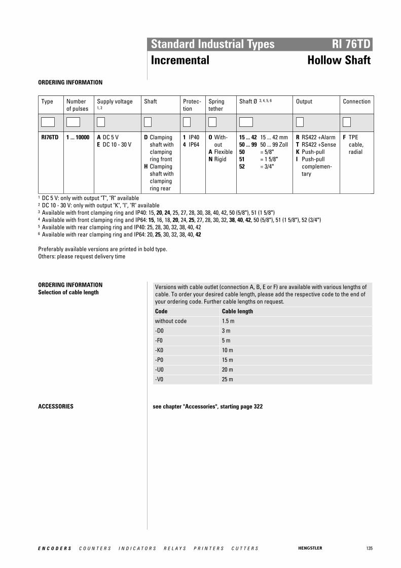
135E N C O D E R S C O U N T E R S I N D I C A T O R S R E L A Y S P R I N T E R S C U T T E R S
Standard Industrial Types RI 76TDIncremental Hollow Shaft
ORDERING INFORMATION
Type Numberof pulses
Supply voltage 1, 2
Shaft Protec-tion
Springtether
Shaft Ø 3, 4, 5, 6 Output Connection
RI76TD 1 ... 10000 A DC 5 VE DC 10 - 30 V
D Clampingshaft withclampingring front
H Clampingshaft withclampingring rear
1 IP404 IP64
O With-out
A FlexibleN Rigid
15 ... 42 15 ... 42 mm50 ... 99 50 ... 99 Zoll50 = 5/8"51 = 1 5/8"52 = 3/4"
R RS422 +AlarmT RS422 +SenseK Push-pullI Push-pull
complemen-tary
F TPEcable,radial
1 DC 5 V: only with output "T", "R" available2 DC 10 - 30 V: only with output "K", "I", "R" available3 Available with front clamping ring and IP40: 15, 20, 24, 25, 27, 28, 30, 38, 40, 42, 50 (5/8"), 51 (1 5/8")4 Available with front clamping ring and IP64: 15, 16, 18, 20, 24, 25, 27, 28, 30, 32, 38, 40, 42, 50 (5/8"), 51 (1 5/8"), 52 (3/4")5 Available with rear clamping ring and IP40: 25, 28, 30, 32, 38, 40, 426 Available with rear clamping ring and IP64: 20, 25, 30, 32, 38, 40, 42
Preferably available versions are printed in bold type.Others: please request delivery time
ORDERING INFORMATION Selection of cable length
Versions with cable outlet (connection A, B, E or F) are available with various lengths ofcable. To order your desired cable length, please add the respective code to the end ofyour ordering code. Further cable lengths on request.
Code Cable length
without code 1.5 m
-D0 3 m
-F0 5 m
-K0 10 m
-P0 15 m
-U0 20 m
-V0 25 m
ACCESSORIES see chapter "Accessories", starting page 322

136 E N C O D E R S C O U N T E R S I N D I C A T O R S R E L A Y S P R I N T E R S C U T T E R S
Standard Industrial Types RI 80-EIncremental Hollow Shaft
� Incremental� 30 - 45 mm hollow shaft� Rugged mechanical design� Unbreakable disc� Integrated diagnostic system� Wide voltage range DC 5 - 30 V� Isolated shaft
NUMBER OF PULSES 1024 / 2048 / 2500 / 4096 / 5000 / 10000 Other number of pulses on request
GENERAL INFORMATION The central element of the RI80-E is the latest Hengstler OptoAsic technology, which offersthe following key benefits:
• Highest EMC immunity • Outstanding reliability by reduced number of components and integrated diagnostics
system • Aging compensation by integrated LED light regulation • Integrated monitoring of pollution, disk damage, LED lifetime, temperature
A robust and generously dimensioned mechanical design ensures long maintenance freeoperation.
The RI80-E is ideally suited for applications like: • Geared Elevators • Asynchronous Motors • Industrial Machinery
TECHNICAL DATA mechanical
Housing diameter 100 mm
Shaft diameter 30 mm / 45 mm (Through hollow shaft)
Flange (Mounting of housing)
Tether
Mounting of shaft Keyway, Set screw
Protection class shaft input (EN 60529)
IP50 or IP64
Protection class housing (EN 60529)
IP50 or IP64
Axial endplay of mounting shaft (hubshaft)
± 0.5 mm
Radial runout of mating shaft (hubshaft)
± 0.05 mm
Max. speed IP50: max. 3600 rpmIP64: max. 1500 rpm
Operating temperature -25 °C ... +85 °C
Storage temperature -40 °C ... +70 °C
Material shaft Aluminum, ceramic coating
Material housing Aluminum / glass fiber-reinforced plastic
Weight 670 g
Connection Sub-D connectorCable, radial
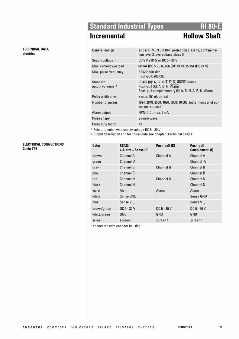
137E N C O D E R S C O U N T E R S I N D I C A T O R S R E L A Y S P R I N T E R S C U T T E R S
Standard Industrial Types RI 80-EIncremental Hollow Shaft
TECHNICAL DATA electrical
General design as per DIN EN 61010-1, protection class III, contamina-tion level 2, overvoltage class II
Supply voltage 1 DC 5 V ±10 % or DC 5 - 30 V
Max. current w/o load 60 mA (DC 5 V), 60 mA (DC 10 V), 35 mA (DC 24 V)
Max. pulse frequency RS422: 600 kHzPush-pull: 200 kHz
Standard output versions 2
RS422 (R): A, B, N, A, B, N, Alarm, SensePush-pull (K): A, B, N, AlarmPush-pull complementary (I): A, B, N, A, B, N, Alarm
Pulse width error ± max. 25° electrical
Number of pulses 1024, 2048, 2500, 4096, 5000, 10 000, (other number of pul-ses on request)
Alarm output NPN-O.C., max. 5 mA
Pulse shape Square wave
Pulse duty factor 1:11 Pole protection with supply voltage DC 5 - 30 V2 Output description and technical data see chapter "Technical basics"
ELECTRICAL CONNECTIONSCable TPE
Color RS422 + Alarm + Sense (R)
Push-pull (K) Push-pull Complement. (I)
brown Channel A Channel A Channel A
green Channel A Channel A
gray Channel B Channel B Channel B
pink Channel B Channel B
red Channel N Channel N Channel N
black Channel N Channel N
violet Alarm Alarm Alarm
white Sense GND Sense GND
blue Sense V cc Sense V cc
brown/green DC 5 - 30 V DC 5 - 30 V DC 5 - 30 V
white/green GND GND GND
screen 1 screen 1 screen 1 screen 1
1 connected with encoder housing

138 E N C O D E R S C O U N T E R S I N D I C A T O R S R E L A Y S P R I N T E R S C U T T E R S
Standard Industrial Types RI 80-EIncremental Hollow Shaft
ELECTRICAL CONNECTIONSSub-D connector,15 pole/ 9 pole
Pin Signal 15 pole
Signal 9 pole
1 B GND
2 B +Ub
3 A A
4 A B
5 GND N
6 +Ub A
7 n.c. B
8 screen N
9 N
10 N
11 n.c.
12 n.c.
13 n.c.
14 n.c.
15 n.c.
DIMENSIONED DRAWINGS
Set screw
<1> M4 (depth 6) <2> M4 (2 x 90°) Dimensions in mm

139E N C O D E R S C O U N T E R S I N D I C A T O R S R E L A Y S P R I N T E R S C U T T E R S
Standard Industrial Types RI 80-EIncremental Hollow Shaft
DIMENSIONED DRAWINGS (continued)
Keyway
<1> Connector SUB-D 15 pole <2> M4 (depth 6) Dimensions in mm
ORDERING INFORMATION
Type Numberof pulses 2
Supply voltage
Spring tether Protec-tion
Shaft Output 1 Connection
RI80-E 1024204825004096100005000
A DC 5 VB DC 5 - 30 V
O Withouttether
A Spring tethersingle
B Spring tetherdouble
C RI76 compa-tible (A)
0 IP401 IP504 IP64
G30 Set screw / 30mm
G38 Set screw / 38mm
G40 Set screw / 40mm
G45 Set screw / 45mm
K30 Keyway / 30mm
1" isololated onrequest
R RS422+Alarm+Sense
K HTLI HTL comple-
mentary
F TPE cable, radialE-I M23 connector
(Conin) at 1 m TPEcable, cw
E-D M23 connector(Conin) at 1 m TPEcable, ccw
3 Sub-D connector, 9 pole
4 Sub-D connector, 15 pole
1 Output code "K" and "I": Driver type DL, see < www.ichaus.de >2 Other number of pulses on request

Standard Industrial Types RI 80-EIncremental Hollow Shaft
ORDERING INFORMATION Selection of cable length
Versions with cable outlet (connection A, B, E or F) are available with various lengths ofcable. To order your desired cable length, please add the respective code to the end ofyour ordering code. Further cable lengths on request.
Code Cable length
without code 1.5 m
-D0 3 m
-F0 5 m
-K0 10 m
-P0 15 m
-U0 20 m
-V0 25 m
ACCESSORIES see chapter "Accessories", starting page 322
E N C O D E R S C O U N T E R S I N D I C A T O R S R E L A Y S P R I N T E R S C U T T E R S140

141E N C O D E R S C O U N T E R S I N D I C A T O R S R E L A Y S P R I N T E R S C U T T E R S
Standard Industrial Types Absolute
Absolute shaft encoders, also known as shaft-angle encoders, areby no means used only to detect angular positions. They are also suitable for linear movements that can be converted into rotarymovements by a toothed belt, drive pinion, or wire winch.
The special feature of absolute shaft encoders is that they assign a unique, digitally encoded signal to each individual measured increment. The method of transducing prevents erroneous readings,whether by a power failure, or by a transient malfunction. After theencoder is switched on again, or power is restored, the position canbe read out. It is not necessary to move to a reference position, as itis for shaft encoders of the incremental type.
Examples of application for absolute encoders
■ overhead support robots■ ventilation flaps■ spinning machines■ conveyor belts■ cam controllers■ injection moulding machines
■ packaging machinery■ extruders■ folding machines■ printing machines■ high lift storage systems■ stamping machines
Stan
d. In
d.Ab
solu
te
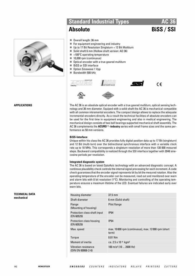
142 E N C O D E R S C O U N T E R S I N D I C A T O R S R E L A Y S P R I N T E R S C U T T E R S
Standard Industrial Types AC 36Absolute BiSS / SSI
� Overall length: 36 mm� For equipment engineering and industry� Up to 17 Bit Resolution Singleturn + 12 Bit Multiturn� Solid shaft 6 mm (Hollow shaft version: AD 36)� +100°C operating temperature� 10,000 rpm (continuous)� Optical encoder with a true geared multiturn� BiSS or SSI interface� Option Sinewave 1 Vpp� Bandwidth 500 kHz
APPLICATIONS The AC 36 is an absolute optical encoder with a true geared multiturn, optical sensing tech-nology and 36 mm diameter. Equiped with a solid-shaft the AC 36 is mechanical compatiblewith all common inkremental encoders. The compact design allows to replace the adequateincremental encoders directly. As a result the technical facilities of absolute encoders canbe used for the first time in equipment engineering and also in medical engineering. Themechanical design consists of two ball bearings supported mechanical shaft assembly. TheAC 36 complements the ACURO ® -industry series with small frame sizes and the same per-formance as 58 mm versions.
BiSS-Interface Unique within his class the AC 36 provides fully digital position data up to 17 Bit (singleturn)and 12 Bit (multi-turn) over the bidirectional synchronous interface with a variable clockrate up to 10 MHz. This corresponds a singleturn resolution of more than 130 000 mesuredsteps. Backward compatibility is realized through the SSI interface together with 2048 sine-cosine periods per revolution.
Integrated diagnostic system The AC 36 is based on latest OptoAsic technology with an advanced diagnostic concept. Acontinous plausibility check controls the internal signal processing for each increment. A codecheck guarantees that the encoder signal represents bit by bit the mesured rotation. Also theoperating temperature of the encoder can be measured, read out and monitored over warnand alarm bits with 8 bit resolution (1°C). Monitoring and controlling of the operating tem-perature ensures a maximum lifetime of the LED. Eventual failures are indicated early overwarn bits.
TECHNICAL DATA mechanical
Housing diameter 37.5 mm
Shaft diameter 6 mm (Solid shaft)
Flange (Mounting of housing)
Pilot flange
Protection class shaft input (EN 60529)
IP64
Protection class housing (EN 60529)
IP64
Max. speed max. 10 000 rpm (continuous), max. 12 000 rpm (shortterm)
Torque 0.01 Nm
Moment of inertia ca. 2.5 x 10 -6 kgm²
Vibration resistance (DIN EN 60068-2-6)
100 m/s² (10 ... 2000 Hz)
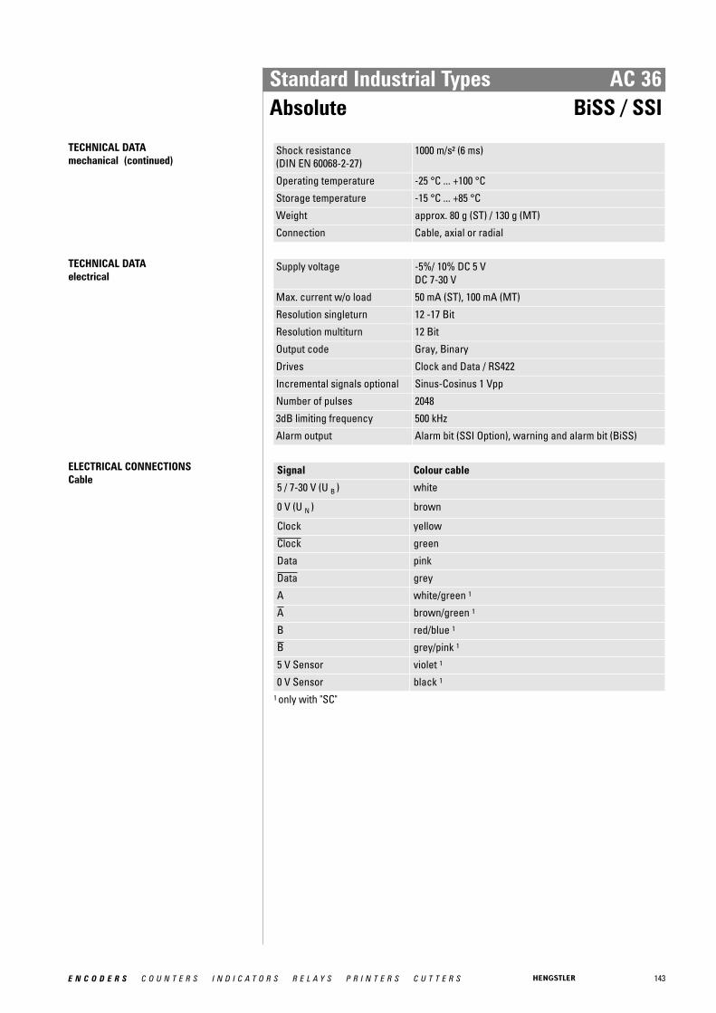
143E N C O D E R S C O U N T E R S I N D I C A T O R S R E L A Y S P R I N T E R S C U T T E R S
Standard Industrial Types AC 36Absolute BiSS / SSI
TECHNICAL DATA mechanical (continued)
Shock resistance (DIN EN 60068-2-27)
1000 m/s² (6 ms)
Operating temperature -25 °C ... +100 °C
Storage temperature -15 °C ... +85 °C
Weight approx. 80 g (ST) / 130 g (MT)
Connection Cable, axial or radial
TECHNICAL DATA electrical
Supply voltage -5%/ 10% DC 5 VDC 7-30 V
Max. current w/o load 50 mA (ST), 100 mA (MT)
Resolution singleturn 12 -17 Bit
Resolution multiturn 12 Bit
Output code Gray, Binary
Drives Clock and Data / RS422
Incremental signals optional Sinus-Cosinus 1 Vpp
Number of pulses 2048
3dB limiting frequency 500 kHz
Alarm output Alarm bit (SSI Option), warning and alarm bit (BiSS)
ELECTRICAL CONNECTIONSCable
Signal Colour cable
5 / 7-30 V (U B ) white
0 V (U N ) brown
Clock yellow
Clock green
Data pink
Data grey
A white/green 1
A brown/green 1
B red/blue 1
B grey/pink 1
5 V Sensor violet 1
0 V Sensor black 1
1 only with "SC"
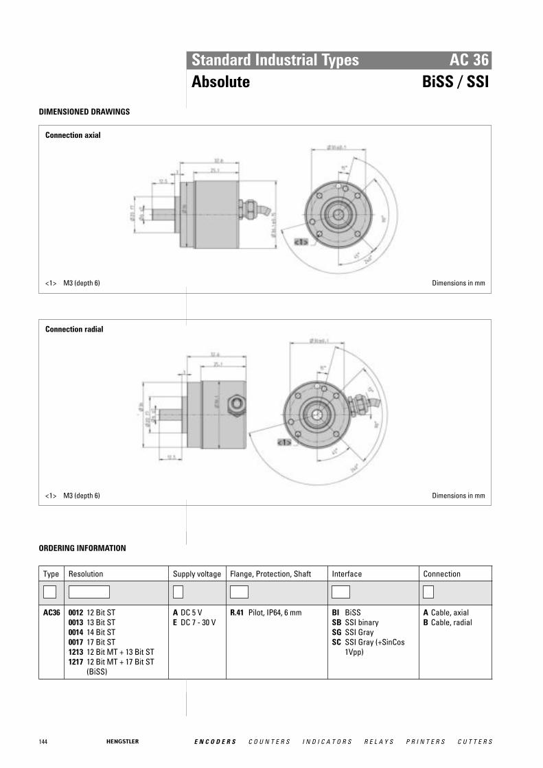
144 E N C O D E R S C O U N T E R S I N D I C A T O R S R E L A Y S P R I N T E R S C U T T E R S
Standard Industrial Types AC 36Absolute BiSS / SSI
DIMENSIONED DRAWINGS
Connection axial
<1> M3 (depth 6) Dimensions in mm
Connection radial
<1> M3 (depth 6) Dimensions in mm
ORDERING INFORMATION
Type Resolution Supply voltage Flange, Protection, Shaft Interface Connection
AC36 0012 12 Bit ST0013 13 Bit ST0014 14 Bit ST0017 17 Bit ST1213 12 Bit MT + 13 Bit ST1217 12 Bit MT + 17 Bit ST
(BiSS)
A DC 5 VE DC 7 - 30 V
R.41 Pilot, IP64, 6 mm BI BiSSSB SSI binarySG SSI GraySC SSI Gray (+SinCos
1Vpp)
A Cable, axialB Cable, radial

145E N C O D E R S C O U N T E R S I N D I C A T O R S R E L A Y S P R I N T E R S C U T T E R S
Standard Industrial Types AC 36Absolute BiSS / SSI
ORDERING INFORMATION Selection of cable length
Versions with cable outlet (connection A, B, E or F) are available with various lengths ofcable. To order your desired cable length, please add the respective code to the end ofyour ordering code. Further cable lengths on request.
Code Cable length
without code 1.5 m
-D0 3 m
-F0 5 m
-K0 10 m
-P0 15 m
-U0 20 m
-V0 25 m
ACCESSORIES see chapter "Accessories”, starting page 322

146 E N C O D E R S C O U N T E R S I N D I C A T O R S R E L A Y S P R I N T E R S C U T T E R S
ElectricalSupply DC 5 VSupply DC 10-30 VPreset key with LED (not IP67)Diagnostics
- LED indication- Warning- Alarm bit- Alarm output- Temperature measurement
Connection for "tico"Parameterization (PC,with Acuro Soft)Parameterization (Bus)Inputs
- Latch- Direction- 2 lines for present input- Tristate
Special Functions- Speed- Acceleration- On time- Round axis- Limit values
Optional 1 VppConnectionsBus cover, 3 cable screwBus cover, 2 cable screw+M12 for "tico"Bus cover, 2 cable screwBus cover, 2 Conin 9-poleBus cover, 2 Conin 12-poleBus cover, 3 M12 4-poleBus cover, 1 M12 5-poleCable axial / radialCable ax /rad 0.1 m+37-pole Sub-DConin 12-pole ax/rad CW/CCWConin 17-pole ax/rad CW/CCWM12 8-pole ax/radMechanicalSynchro fl., shaft 6x10 mm, IP64 or IP67Clamping fl., shaft 10x19.5 mm, IP64 or IP67Clamping fl., shaft 9.52x19.5 mm, IP64 or IP67Hubshaft with tether 10 mm, IP64Hubshaft with tether 12 mm, IP64Hubshaft with tether 12,7 mm, IP64Square flange, 63.5 mm, shaft 9.52x19.5 mm, IP64 or IP67Square flange, 63.5 mm,shaft 10 x 19.5 mm, IP64 or IP67
•••
•
(Option)
(Option)
(Option)
•
•
•
•
•
•
•••••••
•
•••
•••
(Option)
•
•
•
•
•
•
•
•••••••
•
(Option)
•only LED
•
••
•
•
•
•••••••
•
•
•••
•
•
•••
••
••
•
•••••••
•
•
•
•
•
•
••
•
•••••••
•
•
•
•
•
•
•
•
•••••••
•
•
•
•
•
••
••
•
•
•
•••••••
•
•
•
•
•
•
•••••
••
•
•
•
•••••••
•
SSI BiSS Parallel ST Profibus DeviceNet Interbus CAN CANopen
•
•
•
•••••••
•
SUCOnet
••
•
••
•
•
•
•••••••
•
SSI para.
(Option)
••
•
•
••
•
••
•••••••
•
Parallel MT
Absolute Shaft Encoders ACURO industryOverview Functions and Versions AC 58

147E N C O D E R S C O U N T E R S I N D I C A T O R S R E L A Y S P R I N T E R S C U T T E R S
Standard Industrial Types AC 58Absolute BiSS / SSI
Clamping flange
� Compact design: 50 mm length for single or multiturn� Aids for start up and operation: diagnostic LED, preset key with optical response, status
information� Use of sine/ cosine signals for fast control task possible� Control input: Direction� Resolution up to 29 Bit
TECHNICAL DATA mechanical
Housing diameter 58 mm
Shaft diameter 6 mm / 10 mm (Solid shaft)10 mm / 12 mm (Hub shaft)
Flange (Mounting of housing)
Synchro flange, Clamping flange, Tether, Square flange
Protection class shaft input (EN 60529)
IP64 or IP67
Protection class housing (EN 60529)
IP64 or IP67
Shaft load axial / radial 40 N / 60 N
Axial endplay of mounting shaft (hubshaft)
± 1.5 mm
Radial runout of mating shaft (hubshaft)
± 0.2 mm
Max. speed max. 10 000 rpm (continuous), max. 12 000 rpm (shortterm)
Torque 0.01 Ncm
Moment of inertia ca. 3.8 x 10 -6 kgm²
Vibration resistance (DIN EN 60068-2-6)
100 m/s² (10 ... 2000 Hz)
Shock resistance (DIN EN 60068-2-27)
1000 m/s² (6 ms)
Operating temperature -40 °C ... +100 °C
Storage temperature 1 -25 °C ... +85 °C
Weight approx. 260 g (ST) / 310 g (MT)
Connection Cable, axial or radialM23 connector (Conin), 12 pole, axial or radialM12-connector, 8 pole, axial or radial
1 due to packaging
TECHNICAL DATA electrical
Supply voltage ± 10% DC 5 V or DC 10 - 30 V
Max. current w/o load 50 mA (ST), 100 mA (MT)
Resolution singleturn 10 - 17 BitGray Excess: 360, 720 increments
Resolution multiturn 12 Bit
Output code Binary, Gray
Drives Clock and Data / RS422
Linearity ± ½ LSB (± 1 LSB for resolution > 13 Bit)
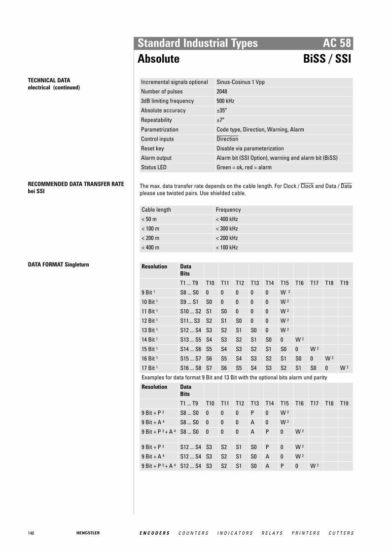
148 E N C O D E R S C O U N T E R S I N D I C A T O R S R E L A Y S P R I N T E R S C U T T E R S
Standard Industrial Types AC 58Absolute BiSS / SSI
TECHNICAL DATA electrical (continued)
Incremental signals optional Sinus-Cosinus 1 Vpp
Number of pulses 2048
3dB limiting frequency 500 kHz
Absolute accuracy ±35"
Repeatability ±7"
Parametrization Code type, Direction, Warning, Alarm
Control inputs Direction
Reset key Disable via parameterization
Alarm output Alarm bit (SSI Option), warning and alarm bit (BiSS)
Status LED Green = ok, red = alarm
RECOMMENDED DATA TRANSFER RATEbei SSI
The max. data transfer rate depends on the cable length. For Clock / Clock and Data / Dataplease use twisted pairs. Use shielded cable.
Cable length Frequency
< 50 m < 400 kHz
< 100 m < 300 kHz
< 200 m < 200 kHz
< 400 m < 100 kHz
DATA FORMAT Singleturn Resolution DataBits
T1 ... T9 T10 T11 T12 T13 T14 T15 T16 T17 T18 T19
9 Bit 1 S8 ... S0 0 0 0 0 0 W 2
10 Bit 1 S9 ... S1 S0 0 0 0 0 W 2
11 Bit 1 S10 ... S2 S1 S0 0 0 0 W 2
12 Bit 1 S11... S3 S2 S1 S0 0 0 W 2
13 Bit 1 S12 ... S4 S3 S2 S1 S0 0 W 2
14 Bit 1 S13 ... S5 S4 S3 S2 S1 S0 0 W 2
15 Bit 1 S14 ... S6 S5 S4 S3 S2 S1 S0 0 W 2
16 Bit 1 S15 ... S7 S6 S5 S4 S3 S2 S1 S0 0 W 2
17 Bit 1 S16 ... S8 S7 S6 S5 S4 S3 S2 S1 S0 0 W 2
Examples for data format 9 Bit and 13 Bit with the optional bits alarm und parity
Resolution DataBits
T1 ... T9 T10 T11 T12 T13 T14 T15 T16 T17 T18 T19
9 Bit + P 3 S8 ... S0 0 0 0 P 0 W 2
9 Bit + A 4 S8 ... S0 0 0 0 A 0 W 2
9 Bit + P 3 + A 4 S8 ... S0 0 0 0 A P 0 W 2
9 Bit + P 3 S12 ... S4 S3 S2 S1 S0 P 0 W 2
9 Bit + A 4 S12 ... S4 S3 S2 S1 S0 A 0 W 2
9 Bit + P 3 + A 4 S12 ... S4 S3 S2 S1 S0 A P 0 W 2

149E N C O D E R S C O U N T E R S I N D I C A T O R S R E L A Y S P R I N T E R S C U T T E R S
Standard Industrial Types AC 58Absolute BiSS / SSI
DATA FORMAT Multiturn Resolution Data bits
T1 ... T12 T13 ... T21 T22 T23 T24 T25
24 Bit 1 M11 ... M0 S11 ... S2 S1 S0 0 W 2
25 Bit 1 M11 ... M0 S12 ... S3 S2 S1 S0 0 W 2
26 Bit 1 M11 ... M0 S13 ... S4 S3 S2 S1 S0 0 W 2
Example for data format 24 Bit with the optional bits alarm und parity
24 Bit + P 3 M11 ... M0 S11 ... S2 S1 S0 P 0 W 2
24 Bit + A 4 M11 ... M0 S11 ... S2 S1 S0 A 0 W 2
24 Bit + P 3 + A 4 M11 ... M0 S11 ... S2 S1 S0 A P 0 W 2
S0 ... S16 Data bits for resolution per revolution
M0 ... M11 Data bits for number of revolutions (only for multiturn) 1 Options (Parity bit, alarm and parity bit, zero bit) on request 2 W: from this data bit on the data iteration for multiplex starts 3 Parity bit: Even Parity (The parity bit expands the data bits to an even nummber of 1-
bits). (Option)
4 Alarm bit: is set to "1" when over temperature, under temperature, disc breakage anddefect LED
SYNCHRONOUS-SERAL TRANSFER (SSI) Synchronous readout of the encoder data isaccording to the clock rate given by theSSI-counterpart. The number of clock rates is determined bythe type of encoder (singleturn resp. multi-turn) and the configuration of the specialBits as defined. For multiple transactions (the stored valueis readout several times successively) afixed clock rate per transaction must bekept (for singleturn 13 resp. 14 clocks, formultiturn 25 resp. 26 clocks). • In the rest position, when the last clock
brush has passed by more than 30μs, thedata output is logically at "1".
• With the first descending clock edge theencoder data and the special bits are
loaded in the shift register of the enco-der interface.
• With each ascending clock edge thedata bits are serially readout, beginningwith the MSB.
• At the end of the data transfer the dataoutput is set to logically "0" for approx.20μs. If within these 20μs a further clockbrush reaches the encoder interface,the already transferred data is readoutonce again. This multiple transfer of thesame data makes it possible to reco-gnize transfer errors.
• After the 20μs the data output goes to itsrest position, logically "1". Subsequentlynew encoder data can be readout.
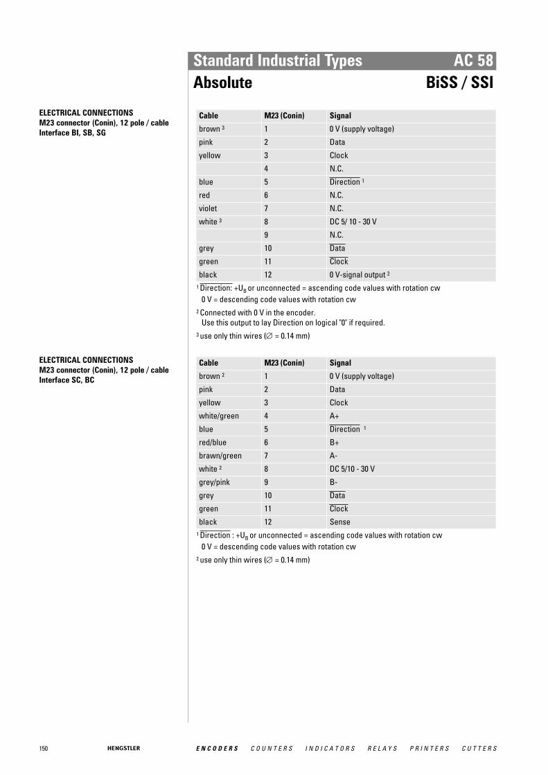
150 E N C O D E R S C O U N T E R S I N D I C A T O R S R E L A Y S P R I N T E R S C U T T E R S
Standard Industrial Types AC 58Absolute BiSS / SSI
ELECTRICAL CONNECTIONSM23 connector (Conin), 12 pole / cable Interface BI, SB, SG
Cable M23 (Conin) Signal
brown 3 1 0 V (supply voltage)
pink 2 Data
yellow 3 Clock
4 N.C.
blue 5 Direction 1
red 6 N.C.
violet 7 N.C.
white 3 8 DC 5/ 10 - 30 V
9 N.C.
grey 10 Data
green 11 Clock
black 12 0 V-signal output 2
1 Direction: +UB or unconnected = ascending code values with rotation cw 0 V = descending code values with rotation cw
2 Connected with 0 V in the encoder. Use this output to lay Direction on logical "0" if required.
3 use only thin wires (∅ = 0.14 mm)
ELECTRICAL CONNECTIONSM23 connector (Conin), 12 pole / cable Interface SC, BC
Cable M23 (Conin) Signal
brown 2 1 0 V (supply voltage)
pink 2 Data
yellow 3 Clock
white/green 4 A+
blue 5 Direction 1
red/blue 6 B+
brawn/green 7 A-
white 2 8 DC 5/10 - 30 V
grey/pink 9 B-
grey 10 Data
green 11 Clock
black 12 Sense 1 Direction : +UB or unconnected = ascending code values with rotation cw
0 V = descending code values with rotation cw 2 use only thin wires (∅ = 0.14 mm)

151E N C O D E R S C O U N T E R S I N D I C A T O R S R E L A Y S P R I N T E R S C U T T E R S
Standard Industrial Types AC 58Absolute BiSS / SSI
ELECTRICAL CONNECTIONSM12 connector, 8 pole
Colour Pin Signal
white 1 DC 10 - 30 V
brown 2 0 V
3 N.C.
green 4 Clock
pink 5 Data
yellow 6 Clock
blue 7 Direction 1 View on connector grey 8 Data
1 Direction: + UB or unconnected = ascending code values with rotation cw 0 V = descending code values with rotation cw
CONNECTION
M12, View on connector
DIMENSIONED DRAWINGS see chapter "Dimensioned drawings AC 58", starting page 185
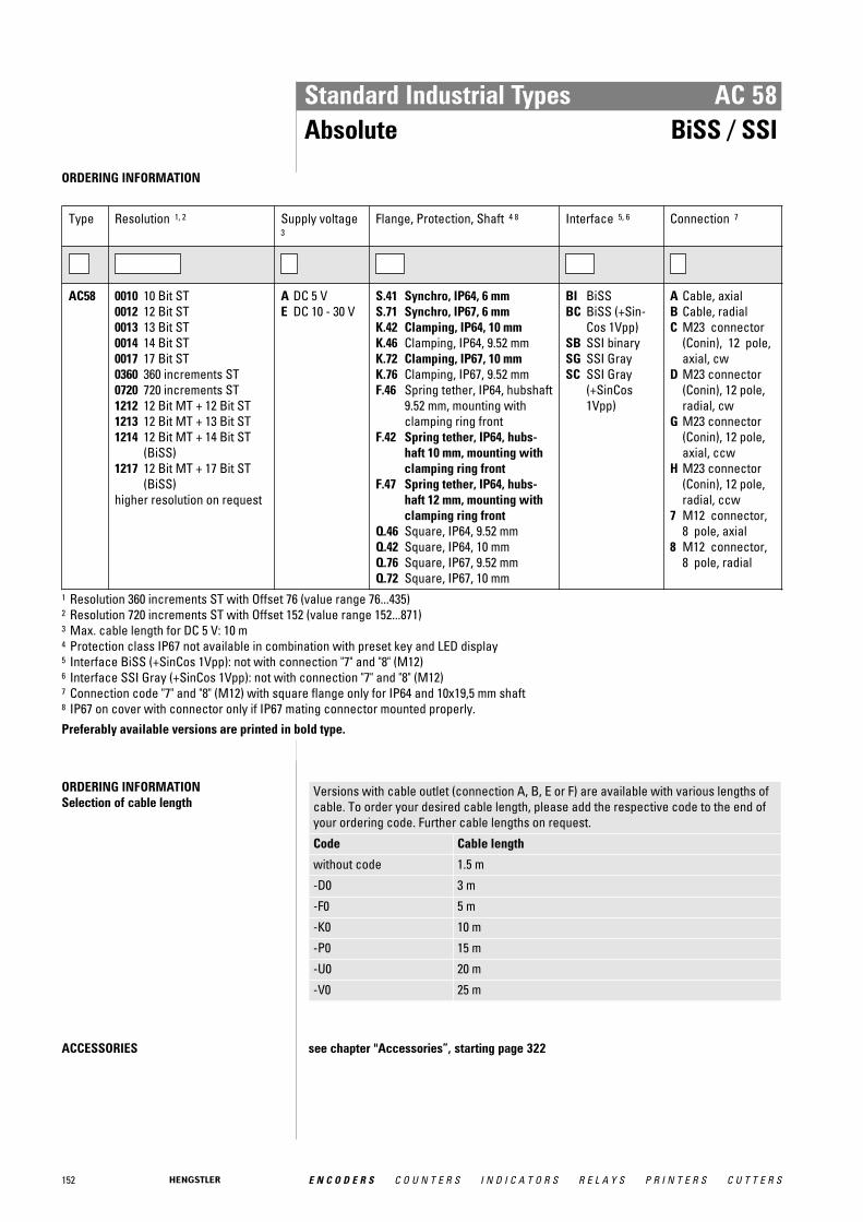
152 E N C O D E R S C O U N T E R S I N D I C A T O R S R E L A Y S P R I N T E R S C U T T E R S
Standard Industrial Types AC 58Absolute BiSS / SSI
ORDERING INFORMATION
Type Resolution 1, 2 Supply voltage3
Flange, Protection, Shaft 4 8 Interface 5, 6 Connection 7
AC58 0010 10 Bit ST0012 12 Bit ST0013 13 Bit ST0014 14 Bit ST0017 17 Bit ST0360 360 increments ST0720 720 increments ST1212 12 Bit MT + 12 Bit ST1213 12 Bit MT + 13 Bit ST1214 12 Bit MT + 14 Bit ST
(BiSS)1217 12 Bit MT + 17 Bit ST
(BiSS)higher resolution on request
A DC 5 VE DC 10 - 30 V
S.41 Synchro, IP64, 6 mmS.71 Synchro, IP67, 6 mmK.42 Clamping, IP64, 10 mmK.46 Clamping, IP64, 9.52 mmK.72 Clamping, IP67, 10 mmK.76 Clamping, IP67, 9.52 mmF.46 Spring tether, IP64, hubshaft
9.52 mm, mounting withclamping ring front
F.42 Spring tether, IP64, hubs-haft 10 mm, mounting withclamping ring front
F.47 Spring tether, IP64, hubs-haft 12 mm, mounting withclamping ring front
Q.46 Square, IP64, 9.52 mmQ.42 Square, IP64, 10 mmQ.76 Square, IP67, 9.52 mmQ.72 Square, IP67, 10 mm
BI BiSSBC BiSS (+Sin-
Cos 1Vpp)SB SSI binarySG SSI GraySC SSI Gray
(+SinCos1Vpp)
A Cable, axialB Cable, radialC M23 connector
(Conin), 12 pole,axial, cw
D M23 connector(Conin), 12 pole,radial, cw
G M23 connector(Conin), 12 pole,axial, ccw
H M23 connector(Conin), 12 pole,radial, ccw
7 M12 connector,8 pole, axial
8 M12 connector,8 pole, radial
1 Resolution 360 increments ST with Offset 76 (value range 76...435)2 Resolution 720 increments ST with Offset 152 (value range 152...871)3 Max. cable length for DC 5 V: 10 m4 Protection class IP67 not available in combination with preset key and LED display5 Interface BiSS (+SinCos 1Vpp): not with connection "7" and "8" (M12)6 Interface SSI Gray (+SinCos 1Vpp): not with connection "7" and "8" (M12)7 Connection code "7" and "8" (M12) with square flange only for IP64 and 10x19,5 mm shaft8 IP67 on cover with connector only if IP67 mating connector mounted properly.Preferably available versions are printed in bold type.
ORDERING INFORMATION Selection of cable length
Versions with cable outlet (connection A, B, E or F) are available with various lengths ofcable. To order your desired cable length, please add the respective code to the end ofyour ordering code. Further cable lengths on request.
Code Cable length
without code 1.5 m
-D0 3 m
-F0 5 m
-K0 10 m
-P0 15 m
-U0 20 m
-V0 25 m
ACCESSORIES see chapter "Accessories”, starting page 322
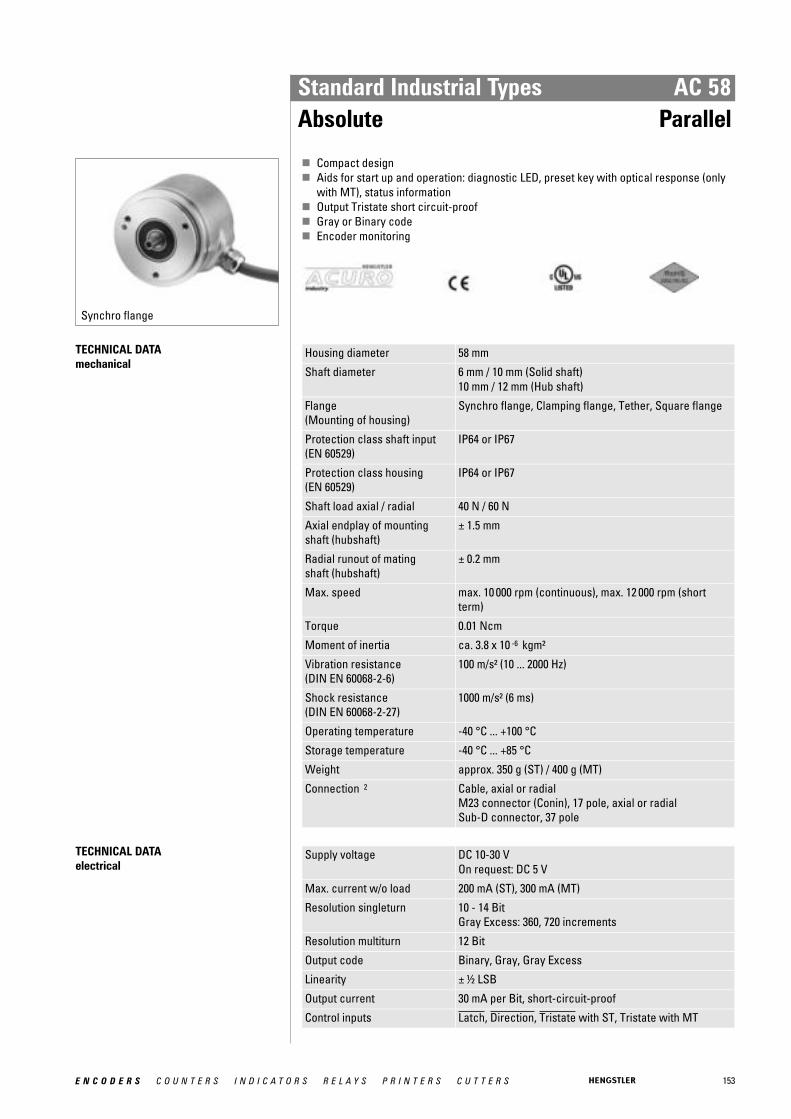
153E N C O D E R S C O U N T E R S I N D I C A T O R S R E L A Y S P R I N T E R S C U T T E R S
Standard Industrial Types AC 58Absolute Parallel
Synchro flange
� Compact design� Aids for start up and operation: diagnostic LED, preset key with optical response (only
with MT), status information� Output Tristate short circuit-proof� Gray or Binary code� Encoder monitoring
TECHNICAL DATA mechanical
Housing diameter 58 mm
Shaft diameter 6 mm / 10 mm (Solid shaft)10 mm / 12 mm (Hub shaft)
Flange (Mounting of housing)
Synchro flange, Clamping flange, Tether, Square flange
Protection class shaft input (EN 60529)
IP64 or IP67
Protection class housing (EN 60529)
IP64 or IP67
Shaft load axial / radial 40 N / 60 N
Axial endplay of mounting shaft (hubshaft)
± 1.5 mm
Radial runout of mating shaft (hubshaft)
± 0.2 mm
Max. speed max. 10 000 rpm (continuous), max. 12 000 rpm (shortterm)
Torque 0.01 Ncm
Moment of inertia ca. 3.8 x 10 -6 kgm²
Vibration resistance (DIN EN 60068-2-6)
100 m/s² (10 ... 2000 Hz)
Shock resistance (DIN EN 60068-2-27)
1000 m/s² (6 ms)
Operating temperature -40 °C ... +100 °C
Storage temperature -40 °C ... +85 °C
Weight approx. 350 g (ST) / 400 g (MT)
Connection 2 Cable, axial or radialM23 connector (Conin), 17 pole, axial or radialSub-D connector, 37 pole
TECHNICAL DATA electrical
Supply voltage DC 10-30 VOn request: DC 5 V
Max. current w/o load 200 mA (ST), 300 mA (MT)
Resolution singleturn 10 - 14 BitGray Excess: 360, 720 increments
Resolution multiturn 12 Bit
Output code Binary, Gray, Gray Excess
Linearity ± ½ LSB
Output current 30 mA per Bit, short-circuit-proof
Control inputs Latch, Direction, Tristate with ST, Tristate with MT

154 E N C O D E R S C O U N T E R S I N D I C A T O R S R E L A Y S P R I N T E R S C U T T E R S
Standard Industrial Types AC 58Absolute Parallel
TECHNICAL DATA electrical (continued)
Alarm output NPN-O.C., max. 5 mA
Status LED Green = ok, red = alarm
Data output level Supply voltage U B DC 5 V - 5 % +10 % 1 DC 10 - 30 V
Output level High ≥ 3.5 V (30 mA) ≥ 3.9 V (10 mA)
≥ U B -2.2 V (30 mA) ≥ U B -1.8 V (10 mA)
Output level Low ≤ 1.6 V (30 mA) ≤ 1.2 V (10 mA)
≤ 1.6 V (30 mA) ≤ 1.2 V (10 mA)
Rise time (1.5 m Cable) ≤ 0.1 μs ≤ 0.2 μs
Drop time (1.5 m Cable) ≤ 0.05 μs ≤ 0.1 μs 1 on request
Control inputs
Input Level logical (physical) Function
Direction 1 (+ U B or open) 0 (0 V)
ascending code values when turning clockwise (cw) descending code values when turning clockwise (cw)
Latch 1 (+ U B or open) 0 (0 V)
encoder data continuously changing at output encoder data stored and constant at output
Tristate (with singleturn) 1 (+ U B or open) 0 (0 V)
outputs active outputs at high impedance (Tristate mode)
Tristate (with multiturn) 1 (+ U B ) 0 (0 V or open)
outputs at high impedance (Tristate mode) outputs active
Typical actuating delay time 10 μs with push-pull selection; when selected via O.C., an external pull-down resistor (1 KΩ) is required

155E N C O D E R S C O U N T E R S I N D I C A T O R S R E L A Y S P R I N T E R S C U T T E R S
Standard Industrial Types AC 58Absolute Parallel
ELECTRICAL CONNECTIONSSingleturn, cable
Colour (PVC) 9 Bit / 360 incr. 10 Bit / 720 incr. 12 Bit 13 Bit 14 Bit
grey/pink N.C. N.C. N.C. N.C. SO (LSB)
brown/yellow N.C. N.C. N.C. SO (LSB) S1
brown/grey N.C. N.C. S0 (LSB) S1 S2
red/blue N.C. N.C. S1 S2 S3
violet N.C. S0 (LSB) S2 S3 S4
white/brown S0 (LSB) S1 S3 S4 S5
white/green S1 S2 S4 S5 S6
white/yellow S2 S3 S5 S6 S7
white/grey S3 S4 S6 S7 S8
white/pink S4 S5 S7 S8 S9
white/blue S5 S6 S8 S9 S10
white/red S6 S7 S9 S10 S11
white/black S7 S8 S10 S11 S12
brown/green S8 (MSB) S9 (MSB) S11 (MSB) S12 (MSB) S13 (MSB)
yellow Tristate S0...S8 Tristate S0...S9 Tristate S0...S11 Tristate S0...S12 Tristate S0...S13
pink Latch Latch Latch Latch Latch
green Direction Direction Direction Direction Direction
black 0 V 0 V 0 V 0 V 0 V
red DC 5 V/ 10-30 V DC 5 V/ 10-30 V DC 5 V/ 10-30 V DC 5 V/ 10-30 V DC 5 V/ 10-30 V
brown Alarm Alarm Alarm Alarm Alarm
ELECTRICAL CONNECTIONSSingleturn, M23 connector (Conin), 17 pole
Pin 9 Bit / 360 incr. 10 Bit / 720 incr. 12 Bit 13 Bit 14 Bit
1 S0 (LSB) S0 (LSB) S0 (LSB) S12 (MSB) S13 (MSB)
2 S1 S1 S1 S11 S12
3 S2 S2 S2 S10 S11
4 S3 S3 S3 S9 S10
5 S4 S4 S4 S8 S9
6 S5 S5 S5 S7 S8
7 S6 S6 S6 S6 S7
8 S7 S7 S7 S5 S6
9 S8 (MSB) S8 S8 S4 S5
10 N.C. S9 (MSB) S9 S3 S4
11 N.C. N.C. S10 S2 S3
12 Tristate S0...S8 Tristate S0...S9 S11 (MSB) S1 S2
13 Latch Latch Latch S0 (LSB) S1
14 Direction Direction Direction Direction S0 (LSB)
15 0 V 0 V 0 V 0 V 0 V
16 DC 5 V/ 10-30 V DC 5 V/ 10-30 V DC 5 V/ 10-30 V DC 5 V/ 10-30 V DC 5 V/ 10-30 V
17 Alarm Alarm Alarm Latch/Alarm Latch/Alarm

156 E N C O D E R S C O U N T E R S I N D I C A T O R S R E L A Y S P R I N T E R S C U T T E R S
Standard Industrial Types AC 58Absolute Parallel
ELECTRICAL CONNECTIONSMultiturn, cable
Cable (TPE) 10 cm cable with Sub-D connector, 37pole
Cable (TPE) 10 cm cable with Sub-D connector, 37pole
Colour Pin Connection Colour Pin Connection
brown 2 S0 white/blue 14 M4 1
green 21 S1 brown/blue 33 M5 1
yellow 3 S2 white/red 15 M6 1
grey 22 S3 brown/red 34 M7 1
pink 4 S4 white/black 16 M8 2
violet 23 S5 brown/black 35 M9 2
grey/pink 5 S6 grey/green 17 M10 2
red/blue 24 S7 yellow/grey 36 M11 2
white/green 6 S8 pink/green 18 Alarm
brown/green 25 S9 yellow/pink 10 Direction
white/yellow 7 S10 green/blue 30 Latch
yellow/brown 26 S11 yellow/blue 12 Tristate
white/grey 8 M0 red (0.5mm 2 ) 13 DC 10-30 V
grey/brown 27 M1 white (0.5mm 2 ) 31 DC 10-30 V
white/pink 9 M2 blue (0.5mm 2 ) 1 0 V
pink/brown 28 M3 black (0.5mm 2 ) 20 0 V 1 N. C. with resolution 16 Bit (4 Bit MT) 2 N. C. with resolution 16 Bit or 20 Bit (4 or 8 Bit MT)
DIMENSIONED DRAWINGS see chapter "Dimensioned drawings AC 58", starting page 185

157E N C O D E R S C O U N T E R S I N D I C A T O R S R E L A Y S P R I N T E R S C U T T E R S
Standard Industrial Types AC 58Absolute Parallel
ORDERING INFORMATION
Type Resolution 1, 2 Supply voltage Flange, Protection, Shaft 3 7 Interface Connection 4, 5, 6
AC58 0010 10 Bit ST0012 12 Bit ST0013 13 Bit ST0014 14 Bit ST0360 360 increments ST0720 720 increments ST0412 4 Bit MT + 12 Bit ST0812 8 Bit MT + 12 Bit ST1212 12 Bit MT + 12 Bit ST
E DC 10 - 30 V S.41 Synchro, IP64, 6 mmS.71 Synchro, IP67, 6 mmK.42 Clamping, IP64, 10 mmK.46 Clamping, IP64, 9.52 mmK.72 Clamping, IP67, 10 mmK.76 Clamping, IP67, 9.52 mmF.46 Spring tether, IP64, hubs-
haft 9.52 mm, mounting withclamping ring front
F.42 Spring tether, IP64, hubs-haft 10 mm, mounting withclamping ring front
F.47 Spring tether, IP64, hubs-haft 12 mm, mounting withclamping ring front
Q.46 Square, IP64, 9.52 mmQ.42 Square, IP64, 10 mmQ.76 Square, IP67, 9.52 mmQ.72 Square, IP67, 10 mm
PB Parallelbinary
PG ParallelGray
A Cable, axialB Cable, radialU M23 connector
(Conin), 17 pole,axial, ccw
V M23 connector(Conin), 17 pole,radial, ccw
W M23 connector(Conin), 17 pole,axial, cw
Y M23 connector(Conin), 17 pole,radial, cw
A-A1-F 0,1 m cable withSub-D connector,37 pole, axial
B-B1-F 0,1 m cable withSub-D connector,37 pole, radial
1 Resolution 360 increments ST with Offset 76 (value range 76...435)2 Resolution 720 increments ST with Offset 152 (value range 152...871)3 Protection class IP67 not available in combination with preset key and LED display4 Connection code "A", "B" (cable): ST and MT5 Connection code "U", "V", "W", "Y" (M23 connector): only ST6 Connection code "A-A1-F" and "B-B1-F" (Sub-D connector): only MT7 IP67 on cover with connector only if IP67 mating connector mounted properly.Preferably available versions are printed in bold type.
ORDERING INFORMATION Selection of cable length
Versions with cable outlet (connection A, B, E or F) are available with various lengths ofcable. To order your desired cable length, please add the respective code to the end ofyour ordering code. Further cable lengths on request.
Code Cable length
without code 1.5 m
-D0 3 m
-F0 5 m
-K0 10 m
-P0 15 m
-U0 20 m
-V0 25 m
ACCESSORIES see chapter "Accessories”, starting page 322
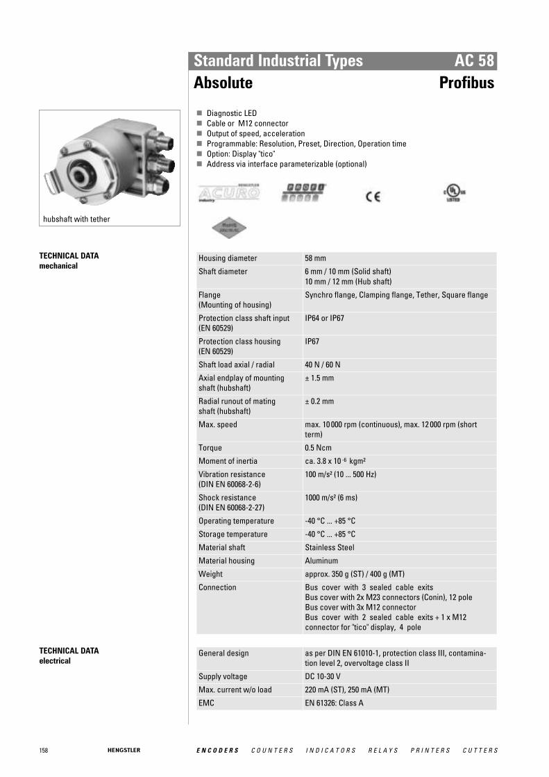
158 E N C O D E R S C O U N T E R S I N D I C A T O R S R E L A Y S P R I N T E R S C U T T E R S
Standard Industrial Types AC 58Absolute Profibus
hubshaft with tether
� Diagnostic LED� Cable or M12 connector� Output of speed, acceleration� Programmable: Resolution, Preset, Direction, Operation time� Option: Display "tico"� Address via interface parameterizable (optional)
TECHNICAL DATA mechanical
Housing diameter 58 mm
Shaft diameter 6 mm / 10 mm (Solid shaft)10 mm / 12 mm (Hub shaft)
Flange (Mounting of housing)
Synchro flange, Clamping flange, Tether, Square flange
Protection class shaft input (EN 60529)
IP64 or IP67
Protection class housing (EN 60529)
IP67
Shaft load axial / radial 40 N / 60 N
Axial endplay of mounting shaft (hubshaft)
± 1.5 mm
Radial runout of mating shaft (hubshaft)
± 0.2 mm
Max. speed max. 10 000 rpm (continuous), max. 12 000 rpm (shortterm)
Torque 0.5 Ncm
Moment of inertia ca. 3.8 x 10 -6 kgm²
Vibration resistance (DIN EN 60068-2-6)
100 m/s² (10 ... 500 Hz)
Shock resistance (DIN EN 60068-2-27)
1000 m/s² (6 ms)
Operating temperature -40 °C ... +85 °C
Storage temperature -40 °C ... +85 °C
Material shaft Stainless Steel
Material housing Aluminum
Weight approx. 350 g (ST) / 400 g (MT)
Connection Bus cover with 3 sealed cable exitsBus cover with 2x M23 connectors (Conin), 12 poleBus cover with 3x M12 connectorBus cover with 2 sealed cable exits + 1 x M12connector for "tico" display, 4 pole
TECHNICAL DATA electrical
General design as per DIN EN 61010-1, protection class III, contamina-tion level 2, overvoltage class II
Supply voltage DC 10-30 V
Max. current w/o load 220 mA (ST), 250 mA (MT)
EMC EN 61326: Class A

159E N C O D E R S C O U N T E R S I N D I C A T O R S R E L A Y S P R I N T E R S C U T T E R S
Standard Industrial Types AC 58Absolute Profibus
TECHNICAL DATA electrical (continued)
Resolution singleturn 10 - 14 Bit
Resolution multiturn 12 Bit
Output code Binary
Drives RS 485
Linearity ± ½ LSB (± 1 LSB for resolution 13, 14, 25, 26 Bit)
Profile/ protocol Profibus DP with encoder profile class C2 (parameteriza-ble)
Programmable Resolution, Preset, Direction
Integrated special functions Speed, Acceleration, Operating time
Baud rate is automatically set within a range of 9.6 KBaud through12 MBaud
Device address adjustable with DIP switches, via fieldbus (optional)
Bus termination resistor set via DIP switches
STARTUP (The encoder can be easily andquickly installed and programmed with theGSD file.)

160 E N C O D E R S C O U N T E R S I N D I C A T O R S R E L A Y S P R I N T E R S C U T T E R S
Standard Industrial Types AC 58Absolute Profibus
ELECTRICAL CONNECTIONSBus cover with 2x M23 connectors (Conin), 12 pole
Pin IN (pins) OUT (socket) Description
1 GND 1 Data Ground (M5V) 1
2 A A Receive/Transmit Data-Negative (A)
3
4 B B Receive/Transmit Data-Positive (B)
5
6 VCC 1 +5 V signal output (P5V) 1
7 DC 10 - 30 V DC 10 - 30 V Supply voltage +U B (P24)
8 0 V 0 V Supply voltage Ground (M24)
9
10
11
12
screen screen screen screen connected with encoder housing 1 can be used as power supply for an external bus termination resistor
ELECTRICAL CONNECTIONSBus cover with 3x M12
Pin Connector 1 Connector 2 Socket
1 UB in +5 V signal output (P5V) 1
2 A in A out
3 0 V in Data Ground (M5V) 1
4 B in B out
5 screen screen screen 1 can be used as power supply for an external bus termination resistor
ELECTRICAL CONNECTIONSBus cover with 3 sealed cable exits
Connecting Terminal Signal
1 UB in (DC 10 - 30V)
2 0 V in
3 UB out
4 0 V out
5 B in
6 A in
7 B out
8 A out
DIMENSIONED DRAWINGS see chapter "Dimensioned drawings AC 58", starting page 185
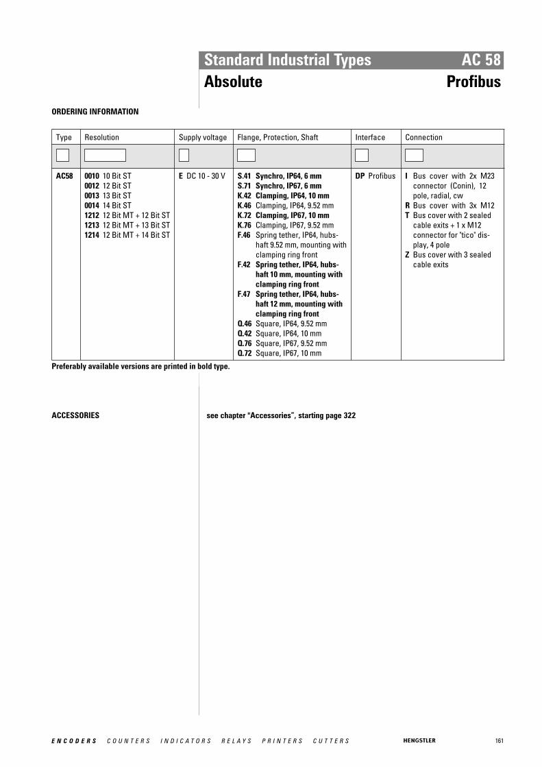
161E N C O D E R S C O U N T E R S I N D I C A T O R S R E L A Y S P R I N T E R S C U T T E R S
Standard Industrial Types AC 58Absolute Profibus
ORDERING INFORMATION
Type Resolution Supply voltage Flange, Protection, Shaft Interface Connection
AC58 0010 10 Bit ST0012 12 Bit ST0013 13 Bit ST0014 14 Bit ST1212 12 Bit MT + 12 Bit ST1213 12 Bit MT + 13 Bit ST1214 12 Bit MT + 14 Bit ST
E DC 10 - 30 V S.41 Synchro, IP64, 6 mmS.71 Synchro, IP67, 6 mmK.42 Clamping, IP64, 10 mmK.46 Clamping, IP64, 9.52 mmK.72 Clamping, IP67, 10 mmK.76 Clamping, IP67, 9.52 mmF.46 Spring tether, IP64, hubs-
haft 9.52 mm, mounting withclamping ring front
F.42 Spring tether, IP64, hubs-haft 10 mm, mounting withclamping ring front
F.47 Spring tether, IP64, hubs-haft 12 mm, mounting withclamping ring front
Q.46 Square, IP64, 9.52 mmQ.42 Square, IP64, 10 mmQ.76 Square, IP67, 9.52 mmQ.72 Square, IP67, 10 mm
DP Profibus I Bus cover with 2x M23connector (Conin), 12pole, radial, cw
R Bus cover with 3x M12T Bus cover with 2 sealed
cable exits + 1 x M12connector for "tico" dis-play, 4 pole
Z Bus cover with 3 sealedcable exits
Preferably available versions are printed in bold type.
ACCESSORIES see chapter "Accessories”, starting page 322

162 E N C O D E R S C O U N T E R S I N D I C A T O R S R E L A Y S P R I N T E R S C U T T E R S
Standard Industrial Types AC 58Absolute CANopen
Clamping flange
� Diagnostic LED� Programmable: Resolution, Preset, Offset, Direction� Output of speed, acceleration� Operation timer� Option: Display "tico"� Address and baud rate via interface parameterizable (optional)
TECHNICAL DATA mechanical
Housing diameter 58 mm
Shaft diameter 6 mm / 10 mm (Solid shaft)10 mm / 12 mm (Hub shaft)
Flange (Mounting of housing)
Synchro flange, Clamping flange, Tether, Square flange
Protection class shaft input (EN 60529)
IP64 or IP67
Protection class housing (EN 60529)
Connection bus cover: IP67Connection cable or M23 (conin): IP64 (IP67 optional)
Shaft load axial / radial 40 N / 60 N
Axial endplay of mounting shaft (hubshaft)
± 1.5 mm
Radial runout of mating shaft (hubshaft)
± 0.2 mm
Max. speed max. 10 000 rpm (continuous), max. 12 000 rpm (shortterm)
Torque 0.5 Ncm
Moment of inertia ca. 3.8 x 10 -6 kgm²
Vibration resistance (DIN EN 60068-2-6)
100 m/s² (10 ... 500 Hz)
Shock resistance (DIN EN 60068-2-27)
1000 m/s² (6 ms)
Operating temperature -40 °C ... +85 °C
Storage temperature -40 °C ... +85 °C
Material shaft Stainless Steel
Material housing Aluminum
Weight approx. 350 g (ST) / 400 g (MT)
Connection Cable, axial or radialM23 connector (Conin), 12 pole, axial or radialBus cover with 3 sealed cable exitsBus cover with 2x M23 connectors (Conin), 9 poleBus cover with 2 sealed cable exits + 1 x M12connector for "tico" display, 4 pole
TECHNICAL DATA electrical
General design as per DIN EN 61010-1, protection class III, contamina-tion level 2, overvoltage class II
Supply voltage DC 10-30 V
Max. current w/o load 220 mA (ST), 250 mA (MT)
EMC EN 61326: Class A

163E N C O D E R S C O U N T E R S I N D I C A T O R S R E L A Y S P R I N T E R S C U T T E R S
Standard Industrial Types AC 58Absolute CANopen
TECHNICAL DATA electrical (continued)
Resolution singleturn 10 - 16 Bit
Resolution multiturn 12 Bit
Output code Binary
Linearity ± ½ LSB (± 1 LSB for resolution 13, 14, 25, 26 Bit)
Profile/ protocol CANopen according to DS 301 with profile DSP 406, pro-grammable encoder according class C2
Programmable Resolution, Preset, Offset, Direction
Integrated special functions Speed, Acceleration, Limit values, Operating time
Baud rate set via DIP switches within a range of 10 through 1000Kbit/s
Bus termination resistor set via DIP switches
Updating of values every millisecond (adjustable), on request
Basic identifier set via DIP switches
ELECTRICAL CONNECTIONSBus cover with 2x M23 connectors (Conin), 9 pole
M23-PIN (Conin) Pin insert (IN) Socket insert (OUT)
1 CAN in + CAN out +
2 CAN in - CAN out-
3 CAN GND in CAN GND out
4 N.C. N.C.
5 N.C. N.C.
6 N.C. N.C.
7 UB in UB out
8 0 V in 0 V out
9 N.C. N.C.
screen screen 1 screen 1
1 screen connected with encoder housing
ELECTRICAL CONNECTIONSM23 connector (Conin), 12 pole / cable
M23-Pin(Conin)
TPE cable Cable pairs Signal
7 yellow Pair 1 CAN in+
2 green CAN in -
4 pink Pair 2 CAN out +
5 grey CAN out -
3 blue CAN GND in
11 brown CAN GND out
12 white Pair 3 UB in
10 brown 0 V in
screen screen screen
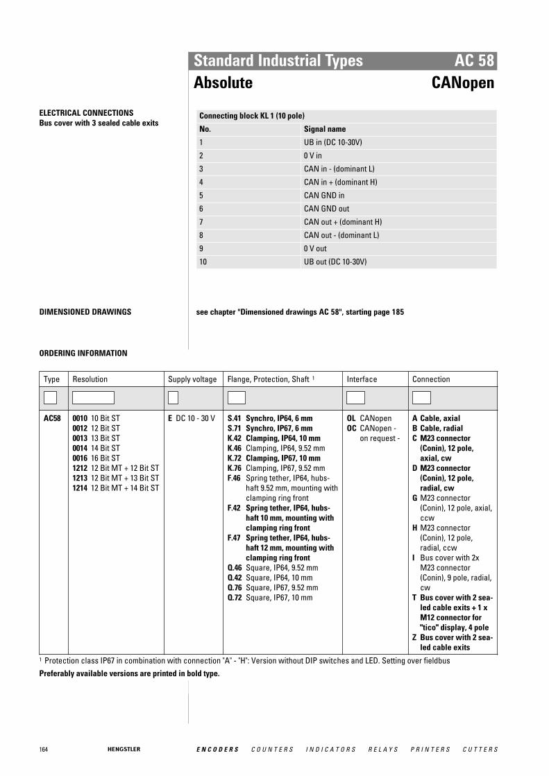
164 E N C O D E R S C O U N T E R S I N D I C A T O R S R E L A Y S P R I N T E R S C U T T E R S
Standard Industrial Types AC 58Absolute CANopen
ELECTRICAL CONNECTIONSBus cover with 3 sealed cable exits
Connecting block KL 1 (10 pole)
No. Signal name
1 UB in (DC 10-30V)
2 0 V in
3 CAN in - (dominant L)
4 CAN in + (dominant H)
5 CAN GND in
6 CAN GND out
7 CAN out + (dominant H)
8 CAN out - (dominant L)
9 0 V out
10 UB out (DC 10-30V)
DIMENSIONED DRAWINGS see chapter "Dimensioned drawings AC 58", starting page 185
ORDERING INFORMATION
Type Resolution Supply voltage Flange, Protection, Shaft 1 Interface Connection
AC58 0010 10 Bit ST0012 12 Bit ST0013 13 Bit ST0014 14 Bit ST0016 16 Bit ST1212 12 Bit MT + 12 Bit ST1213 12 Bit MT + 13 Bit ST1214 12 Bit MT + 14 Bit ST
E DC 10 - 30 V S.41 Synchro, IP64, 6 mmS.71 Synchro, IP67, 6 mmK.42 Clamping, IP64, 10 mmK.46 Clamping, IP64, 9.52 mmK.72 Clamping, IP67, 10 mmK.76 Clamping, IP67, 9.52 mmF.46 Spring tether, IP64, hubs-
haft 9.52 mm, mounting withclamping ring front
F.42 Spring tether, IP64, hubs-haft 10 mm, mounting withclamping ring front
F.47 Spring tether, IP64, hubs-haft 12 mm, mounting withclamping ring front
Q.46 Square, IP64, 9.52 mmQ.42 Square, IP64, 10 mmQ.76 Square, IP67, 9.52 mmQ.72 Square, IP67, 10 mm
OL CANopenOC CANopen -
on request -
A Cable, axialB Cable, radialC M23 connector
(Conin), 12 pole,axial, cw
D M23 connector(Conin), 12 pole,radial, cw
G M23 connector(Conin), 12 pole, axial,ccw
H M23 connector(Conin), 12 pole,radial, ccw
I Bus cover with 2xM23 connector(Conin), 9 pole, radial,cw
T Bus cover with 2 sea-led cable exits + 1 xM12 connector for"tico" display, 4 pole
Z Bus cover with 2 sea-led cable exits
1 Protection class IP67 in combination with connection "A" - "H": Version without DIP switches and LED. Setting over fieldbusPreferably available versions are printed in bold type.
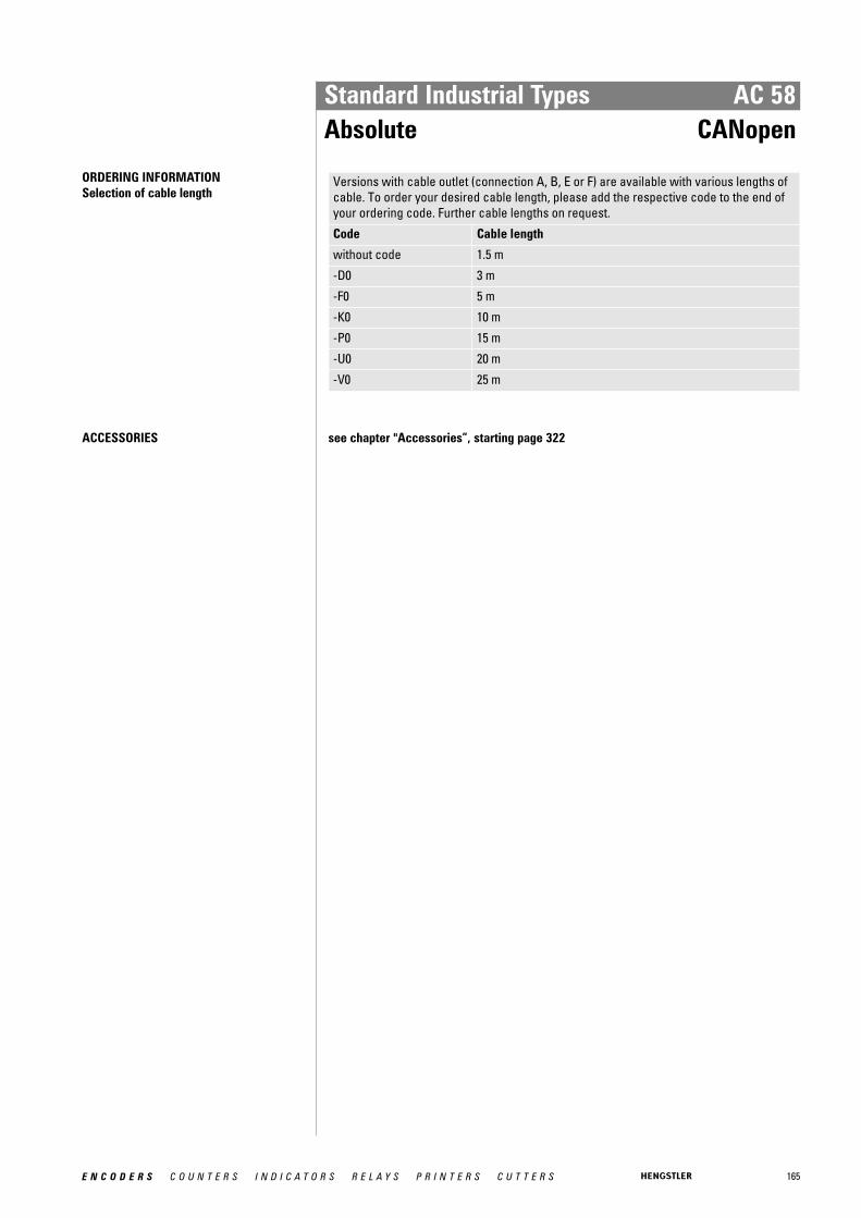
165E N C O D E R S C O U N T E R S I N D I C A T O R S R E L A Y S P R I N T E R S C U T T E R S
Standard Industrial Types AC 58Absolute CANopen
ORDERING INFORMATION Selection of cable length
Versions with cable outlet (connection A, B, E or F) are available with various lengths ofcable. To order your desired cable length, please add the respective code to the end ofyour ordering code. Further cable lengths on request.
Code Cable length
without code 1.5 m
-D0 3 m
-F0 5 m
-K0 10 m
-P0 15 m
-U0 20 m
-V0 25 m
ACCESSORIES see chapter "Accessories”, starting page 322

166 E N C O D E R S C O U N T E R S I N D I C A T O R S R E L A Y S P R I N T E R S C U T T E R S
Standard Industrial Types AC 58Absolute CANlayer2
Clamping flange
� Diagnostic LED� Poll and auto mode� Programmable: Direction, limit values� Option: Display "tico"
TECHNICAL DATA mechanical
Housing diameter 58 mm
Shaft diameter 6 mm / 10 mm (Solid shaft)10 mm / 12 mm (Hub shaft)
Flange (Mounting of housing)
Synchro flange, Clamping flange, Tether, Square flange
Protection class shaft input (EN 60529)
IP64 or IP67
Protection class housing (EN 60529)
IP67 or IP64 (IP67 optional)
Shaft load axial / radial 40 N / 60 N
Axial endplay of mounting shaft (hubshaft)
± 1.5 mm
Radial runout of mating shaft (hubshaft)
± 0.2 mm
Max. speed max. 10 000 rpm (continuous), max. 12 000 rpm (shortterm)
Torque 0.5 Ncm
Moment of inertia ca. 3.8 x 10 -6 kgm²
Vibration resistance (DIN EN 60068-2-6)
100 m/s² (10 ... 500 Hz)
Shock resistance (DIN EN 60068-2-27)
1000 m/s² (6 ms)
Operating temperature -40 °C ... +85 °C
Storage temperature -40 °C ... +85 °C
Material shaft Stainless Steel
Material housing Aluminum
Weight approx. 350 g (ST) / 400 g (MT)
Connection Cable, axial or radialM23 connector (Conin), 12 pole, axial or radialBus cover with 3 sealed cable exitsBus cover with 2x M23 connectors (Conin), 9 poleBus cover with 2 sealed cable exits + 1 x M12connector for "tico" display, 4 pole
TECHNICAL DATA electrical
General design as per DIN EN 61010-1, protection class III, contamina-tion level 2, overvoltage class II
Supply voltage DC 10-30 V
Max. current w/o load 220 mA (ST), 250 mA (MT)
EMC EN 61326: Class A
Resolution singleturn 10 - 14 Bit
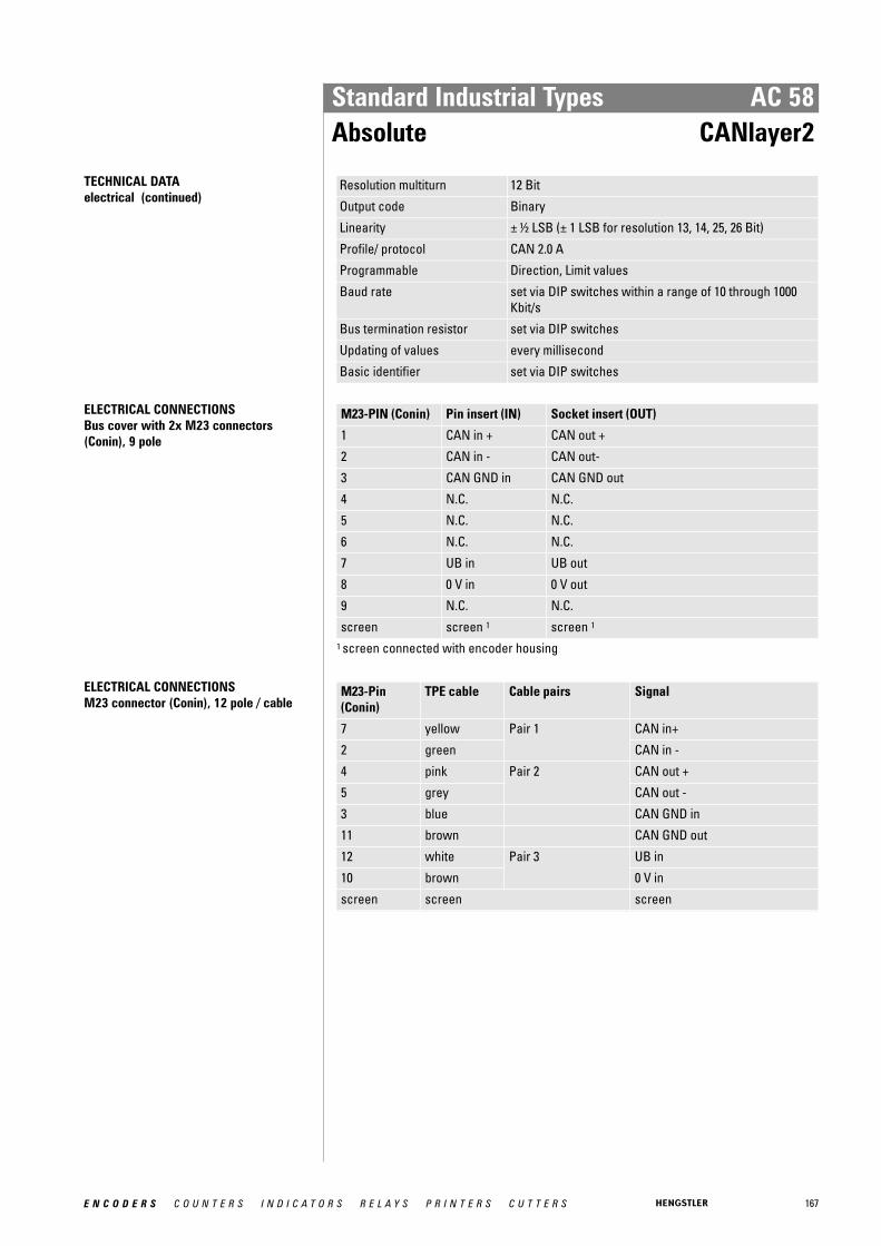
167E N C O D E R S C O U N T E R S I N D I C A T O R S R E L A Y S P R I N T E R S C U T T E R S
Standard Industrial Types AC 58Absolute CANlayer2
TECHNICAL DATA electrical (continued)
Resolution multiturn 12 Bit
Output code Binary
Linearity ± ½ LSB (± 1 LSB for resolution 13, 14, 25, 26 Bit)
Profile/ protocol CAN 2.0 A
Programmable Direction, Limit values
Baud rate set via DIP switches within a range of 10 through 1000Kbit/s
Bus termination resistor set via DIP switches
Updating of values every millisecond
Basic identifier set via DIP switches
ELECTRICAL CONNECTIONSBus cover with 2x M23 connectors (Conin), 9 pole
M23-PIN (Conin) Pin insert (IN) Socket insert (OUT)
1 CAN in + CAN out +
2 CAN in - CAN out-
3 CAN GND in CAN GND out
4 N.C. N.C.
5 N.C. N.C.
6 N.C. N.C.
7 UB in UB out
8 0 V in 0 V out
9 N.C. N.C.
screen screen 1 screen 1
1 screen connected with encoder housing
ELECTRICAL CONNECTIONSM23 connector (Conin), 12 pole / cable
M23-Pin(Conin)
TPE cable Cable pairs Signal
7 yellow Pair 1 CAN in+
2 green CAN in -
4 pink Pair 2 CAN out +
5 grey CAN out -
3 blue CAN GND in
11 brown CAN GND out
12 white Pair 3 UB in
10 brown 0 V in
screen screen screen
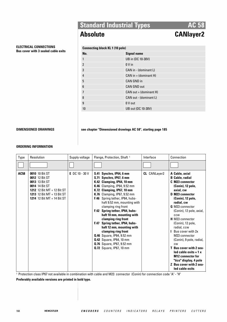
168 E N C O D E R S C O U N T E R S I N D I C A T O R S R E L A Y S P R I N T E R S C U T T E R S
Standard Industrial Types AC 58Absolute CANlayer2
ELECTRICAL CONNECTIONSBus cover with 3 sealed cable exits
Connecting block KL 1 (10 pole)
No. Signal name
1 UB in (DC 10-30V)
2 0 V in
3 CAN in - (dominant L)
4 CAN in + (dominant H)
5 CAN GND in
6 CAN GND out
7 CAN out + (dominant H)
8 CAN out - (dominant L)
9 0 V out
10 UB out (DC 10-30V)
DIMENSIONED DRAWINGS see chapter "Dimensioned drawings AC 58", starting page 185
ORDERING INFORMATION
Type Resolution Supply voltage Flange, Protection, Shaft 1 Interface Connection
AC58 0010 10 Bit ST0012 12 Bit ST0013 13 Bit ST0014 14 Bit ST1212 12 Bit MT + 12 Bit ST1213 12 Bit MT + 13 Bit ST1214 12 Bit MT + 14 Bit ST
E DC 10 - 30 V S.41 Synchro, IP64, 6 mmS.71 Synchro, IP67, 6 mmK.42 Clamping, IP64, 10 mmK.46 Clamping, IP64, 9.52 mmK.72 Clamping, IP67, 10 mmK.76 Clamping, IP67, 9.52 mmF.46 Spring tether, IP64, hubs-
haft 9.52 mm, mounting withclamping ring front
F.42 Spring tether, IP64, hubs-haft 10 mm, mounting withclamping ring front
F.47 Spring tether, IP64, hubs-haft 12 mm, mounting withclamping ring front
Q.46 Square, IP64, 9.52 mmQ.42 Square, IP64, 10 mmQ.76 Square, IP67, 9.52 mmQ.72 Square, IP67, 10 mm
CL CANLayer2 A Cable, axialB Cable, radialC M23 connector
(Conin), 12 pole,axial, cw
D M23 connector(Conin), 12 pole,radial, cw
G M23 connector(Conin), 12 pole, axial,ccw
H M23 connector(Conin), 12 pole,radial, ccw
I Bus cover with 2xM23 connector(Conin), 9 pole, radial,cw
T Bus cover with 2 sea-led cable exits + 1 xM12 connector for"tico" display, 4 pole
Z Bus cover with 2 sea-led cable exits
1 Protection class IP67 not available in combination with cable and M23 connector (Conin) for connection code "A" - "H"Preferably available versions are printed in bold type.
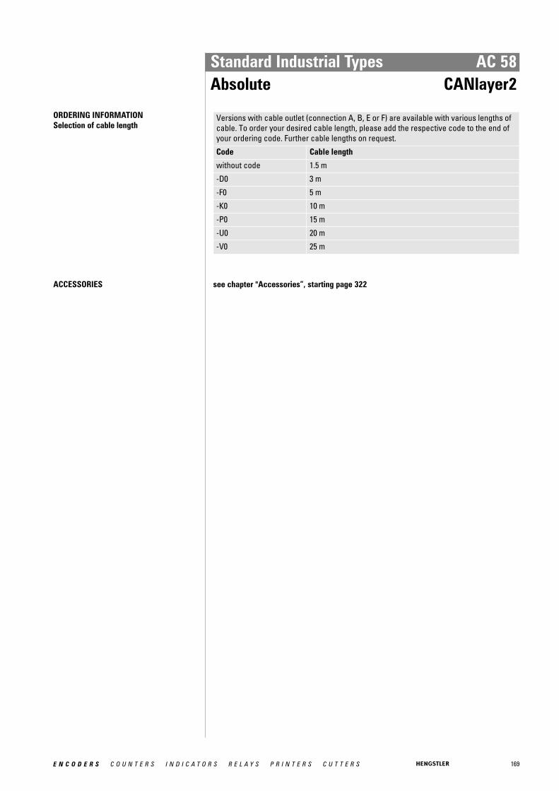
169E N C O D E R S C O U N T E R S I N D I C A T O R S R E L A Y S P R I N T E R S C U T T E R S
Standard Industrial Types AC 58Absolute CANlayer2
ORDERING INFORMATION Selection of cable length
Versions with cable outlet (connection A, B, E or F) are available with various lengths ofcable. To order your desired cable length, please add the respective code to the end ofyour ordering code. Further cable lengths on request.
Code Cable length
without code 1.5 m
-D0 3 m
-F0 5 m
-K0 10 m
-P0 15 m
-U0 20 m
-V0 25 m
ACCESSORIES see chapter "Accessories”, starting page 322
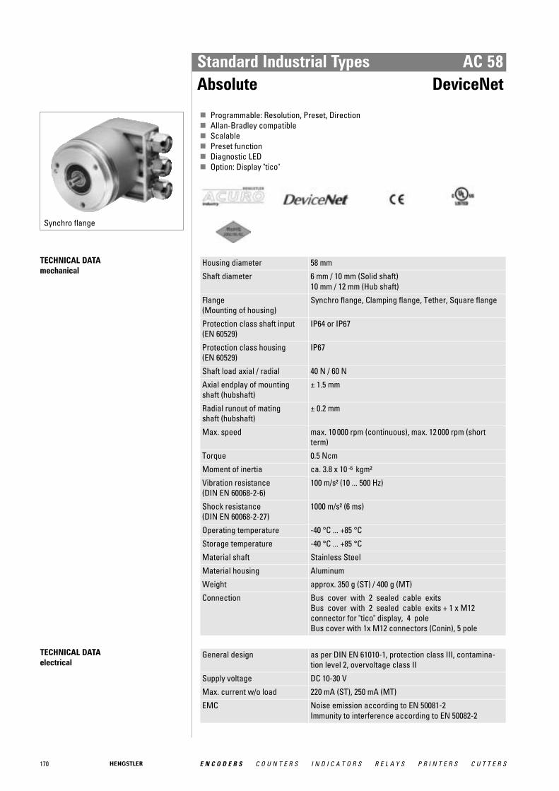
170 E N C O D E R S C O U N T E R S I N D I C A T O R S R E L A Y S P R I N T E R S C U T T E R S
Standard Industrial Types AC 58Absolute DeviceNet
Synchro flange
� Programmable: Resolution, Preset, Direction� Allan-Bradley compatible� Scalable� Preset function� Diagnostic LED� Option: Display "tico"
TECHNICAL DATA mechanical
Housing diameter 58 mm
Shaft diameter 6 mm / 10 mm (Solid shaft)10 mm / 12 mm (Hub shaft)
Flange (Mounting of housing)
Synchro flange, Clamping flange, Tether, Square flange
Protection class shaft input (EN 60529)
IP64 or IP67
Protection class housing (EN 60529)
IP67
Shaft load axial / radial 40 N / 60 N
Axial endplay of mounting shaft (hubshaft)
± 1.5 mm
Radial runout of mating shaft (hubshaft)
± 0.2 mm
Max. speed max. 10 000 rpm (continuous), max. 12 000 rpm (shortterm)
Torque 0.5 Ncm
Moment of inertia ca. 3.8 x 10 -6 kgm²
Vibration resistance (DIN EN 60068-2-6)
100 m/s² (10 ... 500 Hz)
Shock resistance (DIN EN 60068-2-27)
1000 m/s² (6 ms)
Operating temperature -40 °C ... +85 °C
Storage temperature -40 °C ... +85 °C
Material shaft Stainless Steel
Material housing Aluminum
Weight approx. 350 g (ST) / 400 g (MT)
Connection Bus cover with 2 sealed cable exitsBus cover with 2 sealed cable exits + 1 x M12connector for "tico" display, 4 poleBus cover with 1x M12 connectors (Conin), 5 pole
TECHNICAL DATA electrical
General design as per DIN EN 61010-1, protection class III, contamina-tion level 2, overvoltage class II
Supply voltage DC 10-30 V
Max. current w/o load 220 mA (ST), 250 mA (MT)
EMC Noise emission according to EN 50081-2Immunity to interference according to EN 50082-2
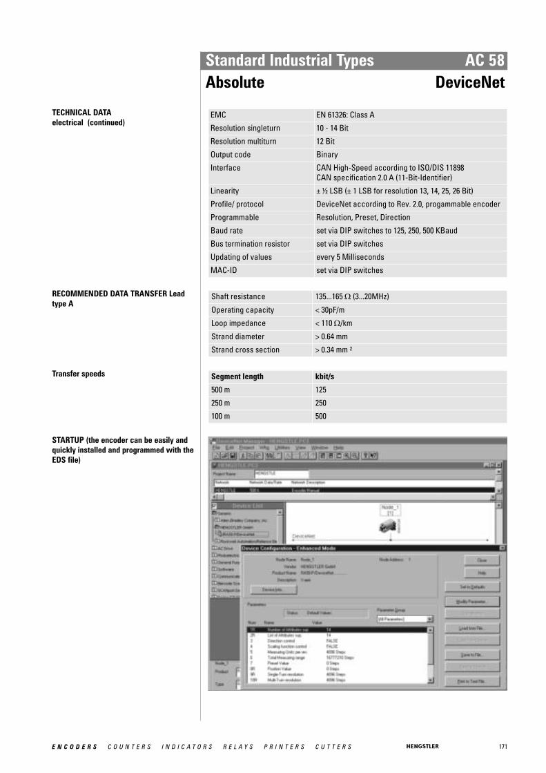
171E N C O D E R S C O U N T E R S I N D I C A T O R S R E L A Y S P R I N T E R S C U T T E R S
Standard Industrial Types AC 58Absolute DeviceNet
TECHNICAL DATA electrical (continued)
EMC EN 61326: Class A
Resolution singleturn 10 - 14 Bit
Resolution multiturn 12 Bit
Output code Binary
Interface CAN High-Speed according to ISO/DIS 11898CAN specification 2.0 A (11-Bit-Identifier)
Linearity ± ½ LSB (± 1 LSB for resolution 13, 14, 25, 26 Bit)
Profile/ protocol DeviceNet according to Rev. 2.0, progammable encoder
Programmable Resolution, Preset, Direction
Baud rate set via DIP switches to 125, 250, 500 KBaud
Bus termination resistor set via DIP switches
Updating of values every 5 Milliseconds
MAC-ID set via DIP switches
RECOMMENDED DATA TRANSFER Leadtype A
Shaft resistance 135...165 Ω (3...20MHz)
Operating capacity < 30pF/m
Loop impedance < 110 Ω/km
Strand diameter > 0.64 mm
Strand cross section > 0.34 mm 2
Transfer speeds Segment length kbit/s
500 m 125
250 m 250
100 m 500
STARTUP (the encoder can be easily andquickly installed and programmed with theEDS file)

172 E N C O D E R S C O U N T E R S I N D I C A T O R S R E L A Y S P R I N T E R S C U T T E R S
Standard Industrial Types AC 58Absolute DeviceNet
ELECTRICAL CONNECTIONSBus cover with 2 sealed cable exits
Terminals
No. Signal name
1 UB in (DC 10 - 30V)
2 0 V in
3 CAN-L
4 CAN-H
5 DRAIN
6 DRAIN
7 DRAIN
8 CAN-L
9 0 V out
10 UB out (DC 10 - 30V)
ELECTRICAL CONNECTIONSBus cover with 1x M12, 5 pole
Pin Connector Colour
1 UB in (DC 10 - 30V) white
2 0 V in blue
3 CAN-L green/yellow
4 CAN-H black
5 DRAIN brown
DIMENSIONED DRAWINGS see chapter "Dimensioned drawings AC 58", starting page 185
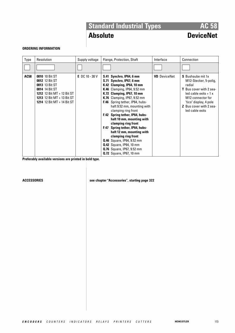
173E N C O D E R S C O U N T E R S I N D I C A T O R S R E L A Y S P R I N T E R S C U T T E R S
Standard Industrial Types AC 58Absolute DeviceNet
ORDERING INFORMATION
Type Resolution Supply voltage Flange, Protection, Shaft Interface Connection
AC58 0010 10 Bit ST0012 12 Bit ST0013 13 Bit ST0014 14 Bit ST1212 12 Bit MT + 12 Bit ST1213 12 Bit MT + 13 Bit ST1214 12 Bit MT + 14 Bit ST
E DC 10 - 30 V S.41 Synchro, IP64, 6 mmS.71 Synchro, IP67, 6 mmK.42 Clamping, IP64, 10 mmK.46 Clamping, IP64, 9.52 mmK.72 Clamping, IP67, 10 mmK.76 Clamping, IP67, 9.52 mmF.46 Spring tether, IP64, hubs-
haft 9.52 mm, mounting withclamping ring front
F.42 Spring tether, IP64, hubs-haft 10 mm, mounting withclamping ring front
F.47 Spring tether, IP64, hubs-haft 12 mm, mounting withclamping ring front
Q.46 Square, IP64, 9.52 mmQ.42 Square, IP64, 10 mmQ.76 Square, IP67, 9.52 mmQ.72 Square, IP67, 10 mm
VD DeviceNet S Bushaube mit 1xM12-Stecker, 5-polig,radial
T Bus cover with 2 sea-led cable exits + 1 xM12 connector for"tico" display, 4 pole
Z Bus cover with 2 sea-led cable exits
Preferably available versions are printed in bold type.
ACCESSORIES see chapter "Accessories”, starting page 322

174 E N C O D E R S C O U N T E R S I N D I C A T O R S R E L A Y S P R I N T E R S C U T T E R S
Standard Industrial Types AC 58Absolute Interbus
hubshaft with tether
� Resolution programmable (K3)� Resolution up to 24 Bit� Preset (K3)� Direction (K3)� Diagnostic LED
TECHNICAL DATA mechanical
Housing diameter 58 mm
Shaft diameter 6 mm / 10 mm (Solid shaft)10 mm / 12 mm (Hub shaft)
Flange (Mounting of housing)
Synchro flange, Clamping flange, Tether, Square flange
Protection class shaft input (EN 60529)
IP64 or IP67
Protection class housing (EN 60529)
Connection bus cover: IP67Connection cable or M23 (conin): IP64 (IP67 optional)
Shaft load axial / radial 40 N / 60 N
Max. speed max. 10 000 rpm (continuous), max. 12 000 rpm (shortterm)
Torque 0.5 Ncm
Moment of inertia ca. 3.8 x 10 -6 kgm²
Vibration resistance (DIN EN 60068-2-6)
100 m/s² (10 ... 500 Hz)
Shock resistance (DIN EN 60068-2-27)
1000 m/s² (6 ms)
Operating temperature -40 °C ... +70 °C
Storage temperature -40 °C ... +85 °C
Material shaft Stainless Steel
Material housing Aluminum
Weight approx. 350 g (ST) / 400 g (MT)
Connection Bus cover with 3 sealed cable exitsBus cover with 2x M23 connectors (Conin), 9 poleCable 1.5 m with M23 connector (Conin), 12 pole, axial orradial
TECHNICAL DATA electrical
General design as per DIN EN 61010-1, protection class III, contamina-tion level 2, overvoltage class II
Supply voltage DC 10-30 V
Max. current w/o load 220 mA (ST, recommended external fuse: T 0.25 A), 250mA (MT, recommended external fuse: T 0.25 A)
EMC Noise emission according to EN 50081-2Immunity to interference according to EN 50082-2
Resolution singleturn 10 - 12 Bit
Resolution multiturn 12 Bit
Output code 32 Bit binary
Linearity ± ½ LSB
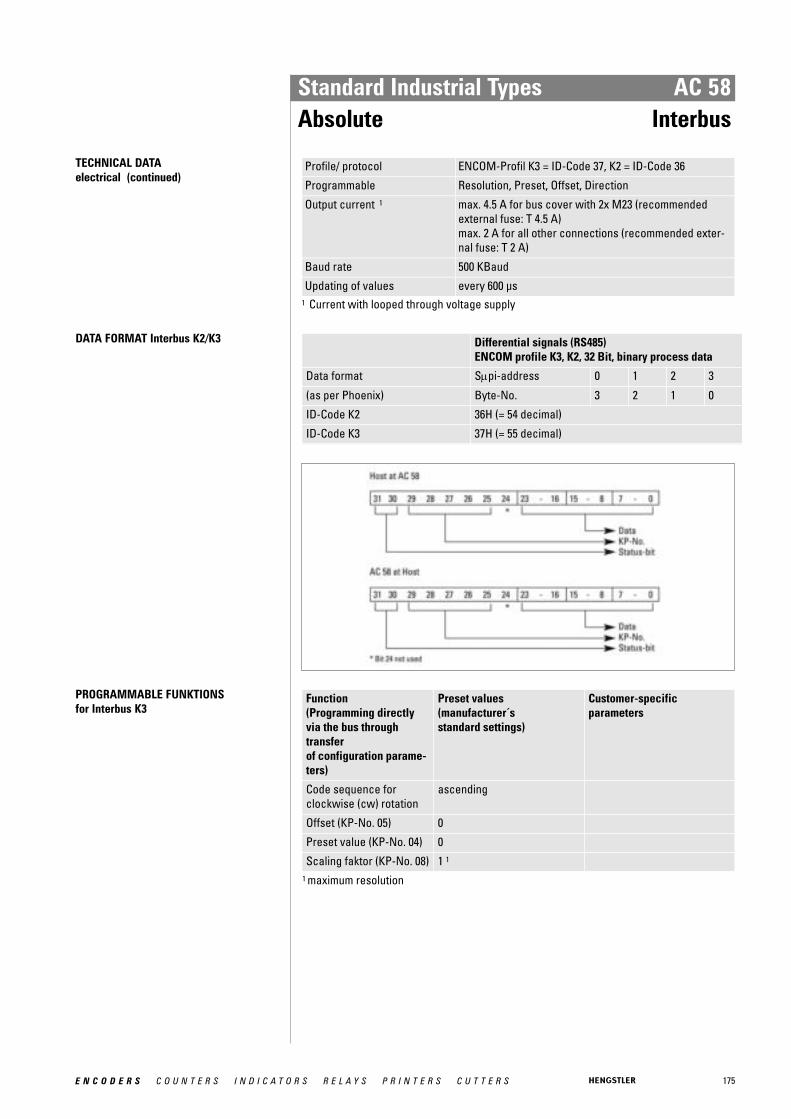
175E N C O D E R S C O U N T E R S I N D I C A T O R S R E L A Y S P R I N T E R S C U T T E R S
Standard Industrial Types AC 58Absolute Interbus
TECHNICAL DATA electrical (continued)
Profile/ protocol ENCOM-Profil K3 = ID-Code 37, K2 = ID-Code 36
Programmable Resolution, Preset, Offset, Direction
Output current 1 max. 4.5 A for bus cover with 2x M23 (recommendedexternal fuse: T 4.5 A)max. 2 A for all other connections (recommended exter-nal fuse: T 2 A)
Baud rate 500 KBaud
Updating of values every 600 μs1 Current with looped through voltage supply
DATA FORMAT Interbus K2/K3 Differential signals (RS485) ENCOM profile K3, K2, 32 Bit, binary process data
Data format Sμpi-address 0 1 2 3
(as per Phoenix) Byte-No. 3 2 1 0
ID-Code K2 36H (= 54 decimal)
ID-Code K3 37H (= 55 decimal)
PROGRAMMABLE FUNKTIONS for Interbus K3
Function (Programming directly via the bus throughtransfer of configuration parame-ters)
Preset values (manufacturer´s standard settings)
Customer-specific parameters
Code sequence for clockwise (cw) rotation
ascending
Offset (KP-No. 05) 0
Preset value (KP-No. 04) 0
Scaling faktor (KP-No. 08) 1 1
1 maximum resolution
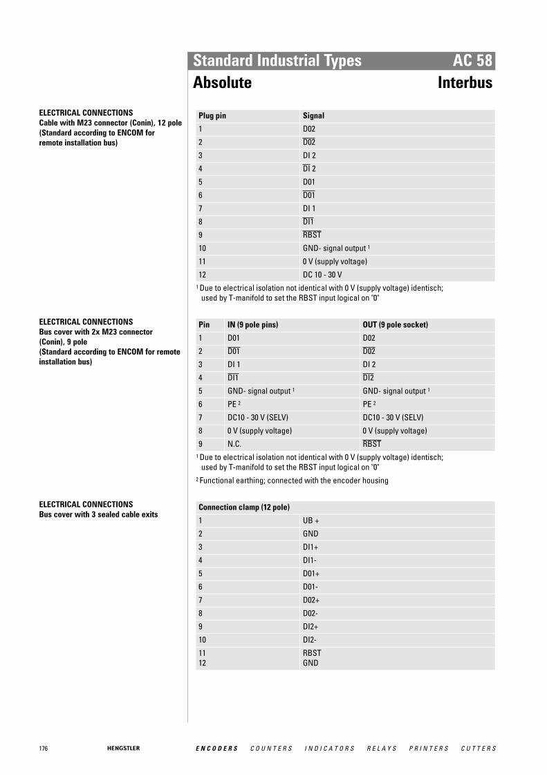
176 E N C O D E R S C O U N T E R S I N D I C A T O R S R E L A Y S P R I N T E R S C U T T E R S
Standard Industrial Types AC 58Absolute Interbus
ELECTRICAL CONNECTIONSCable with M23 connector (Conin), 12 pole (Standard according to ENCOM for remote installation bus)
Plug pin Signal
1 D02
2 D02
3 DI 2
4 DI 2
5 D01
6 D01
7 DI 1
8 DI1
9 RBST
10 GND- signal output 1
11 0 V (supply voltage)
12 DC 10 - 30 V 1 Due to electrical isolation not identical with 0 V (supply voltage) identisch;
used by T-manifold to set the RBST input logical on "0"
ELECTRICAL CONNECTIONSBus cover with 2x M23 connector (Conin), 9 pole (Standard according to ENCOM for remoteinstallation bus)
Pin IN (9 pole pins) OUT (9 pole socket)
1 D01 D02
2 D01 D02
3 DI 1 DI 2
4 DI1 DI2
5 GND- signal output 1 GND- signal output 1
6 PE 2 PE 2
7 DC10 - 30 V (SELV) DC10 - 30 V (SELV)
8 0 V (supply voltage) 0 V (supply voltage)
9 N.C. RBST1 Due to electrical isolation not identical with 0 V (supply voltage) identisch;
used by T-manifold to set the RBST input logical on "0" 2 Functional earthing; connected with the encoder housing
ELECTRICAL CONNECTIONSBus cover with 3 sealed cable exits
Connection clamp (12 pole)
1 UB +
2 GND
3 DI1+
4 DI1-
5 D01+
6 D01-
7 D02+
8 D02-
9 DI2+
10 DI2-
11 12
RBST GND
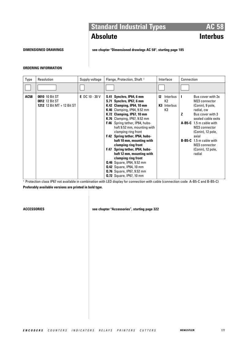
177E N C O D E R S C O U N T E R S I N D I C A T O R S R E L A Y S P R I N T E R S C U T T E R S
Standard Industrial Types AC 58Absolute Interbus
DIMENSIONED DRAWINGS see chapter "Dimensioned drawings AC 58", starting page 185
ORDERING INFORMATION
Type Resolution Supply voltage Flange, Protection, Shaft 1 Interface Connection
AC58 0010 10 Bit ST0012 12 Bit ST1212 12 Bit MT + 12 Bit ST
E DC 10 - 30 V S.41 Synchro, IP64, 6 mmS.71 Synchro, IP67, 6 mmK.42 Clamping, IP64, 10 mmK.46 Clamping, IP64, 9.52 mmK.72 Clamping, IP67, 10 mmK.76 Clamping, IP67, 9.52 mmF.46 Spring tether, IP64, hubs-
haft 9.52 mm, mounting withclamping ring front
F.42 Spring tether, IP64, hubs-haft 10 mm, mounting withclamping ring front
F.47 Spring tether, IP64, hubs-haft 12 mm, mounting withclamping ring front
Q.46 Square, IP64, 9.52 mmQ.42 Square, IP64, 10 mmQ.76 Square, IP67, 9.52 mmQ.72 Square, IP67, 10 mm
I2 InterbusK2
K3 InterbusK3
I Bus cover with 2xM23 connector(Conin), 9 pole,radial, cw
Z Bus cover with 3sealed cable exits
A-B5-C 1.5 m cable withM23 connector(Conin), 12 pole,axial
B-B5-C 1.5 m cable withM23 connector(Conin), 12 pole,radial
1 Protection class IP67 not available in combination with LED display for connection with cable (connection code A-B5-C and B-B5-C)Preferably available versions are printed in bold type.
ACCESSORIES see chapter "Accessories”, starting page 322
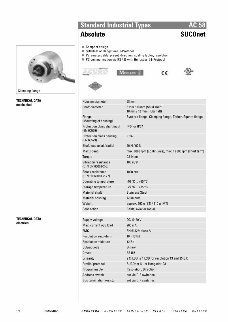
178 E N C O D E R S C O U N T E R S I N D I C A T O R S R E L A Y S P R I N T E R S C U T T E R S
Standard Industrial Types AC 58Absolute SUCOnet
Clamping flange
� Compact design� SUCOnet or Hengstler-G1-Protocol� Parameterizable: preset, direction, scaling factor, resolution� PC communication via RS 485 with Hengstler-G1-Protocol
TECHNICAL DATA mechanical
Housing diameter 58 mm
Shaft diameter 6 mm / 10 mm (Solid shaft)10 mm / 12 mm (Hubshaft)
Flange (Mounting of housing)
Synchro flange, Clamping flange, Tether, Square flange
Protection class shaft input (EN 60529)
IP64 or IP67
Protection class housing (EN 60529)
IP64
Shaft load axial / radial 40 N / 60 N
Max. speed max. 6000 rpm (continuous), max. 12 000 rpm (short term)
Torque 0.5 Ncm
Vibration resistance (DIN EN 60068-2-6)
100 m/s²
Shock resistance (DIN EN 60068-2-27)
1000 m/s²
Operating temperature -10 °C ... +60 °C
Storage temperature -25 °C ... +85 °C
Material shaft Stainless Steel
Material housing Aluminum
Weight approx. 260 g (ST) / 310 g (MT)
Connection Cable, axial or radial
TECHNICAL DATA electrical
Supply voltage DC 10-30 V
Max. current w/o load 200 mA
EMC EN 61326: class A
Resolution singleturn 10 - 13 Bit
Resolution multiturn 12 Bit
Output code Binary
Drives RS485
Linearity ± ½ LSB (± 1 LSB for resolution 13 and 25 Bit)
Profile/ protocol SUCOnet-K1 or Hengstler-G1
Programmable Resolution, Direction
Address switch set via DIP switches
Bus termination resistor set via DIP switches
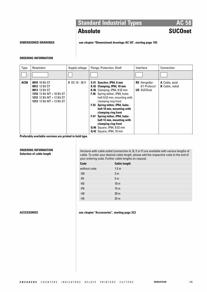
179E N C O D E R S C O U N T E R S I N D I C A T O R S R E L A Y S P R I N T E R S C U T T E R S
Standard Industrial Types AC 58Absolute SUCOnet
DIMENSIONED DRAWINGS see chapter "Dimensioned drawings AC 58", starting page 185
ORDERING INFORMATION
Type Resolution Supply voltage Flange, Protection, Shaft Interface Connection
AC58 0010 10 Bit ST0012 12 Bit ST0013 13 Bit ST1210 12 Bit MT + 10 Bit ST1212 12 Bit MT + 12 Bit ST1213 12 Bit MT + 13 Bit ST
E DC 10 - 30 V S.41 Synchro, IP64, 6 mmK.42 Clamping, IP64, 10 mmK.46 Clamping, IP64, 9.52 mmF.46 Spring tether, IP64, hubs-
haft 9.52 mm, mounting withclamping ring front
F.42 Spring tether, IP64, hubs-haft 10 mm, mounting withclamping ring front
F.47 Spring tether, IP64, hubs-haft 12 mm, mounting withclamping ring front
Q.46 Square, IP64, 9.52 mmQ.42 Square, IP64, 10 mm
RS Hengstler-G1-Protocol
US SUCOnet
A Cable, axialB Cable, radial
Preferably available versions are printed in bold type.
ORDERING INFORMATION Selection of cable length
Versions with cable outlet (connection A, B, E or F) are available with various lengths ofcable. To order your desired cable length, please add the respective code to the end ofyour ordering code. Further cable lengths on request.
Code Cable length
without code 1.5 m
-D0 3 m
-F0 5 m
-K0 10 m
-P0 15 m
-U0 20 m
-V0 25 m
ACCESSORIES see chapter "Accessories”, starting page 322
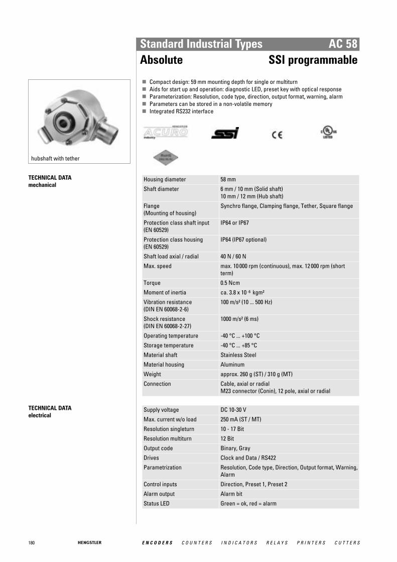
180 E N C O D E R S C O U N T E R S I N D I C A T O R S R E L A Y S P R I N T E R S C U T T E R S
Standard Industrial Types AC 58Absolute SSI programmable
hubshaft with tether
� Compact design: 59 mm mounting depth for single or multiturn� Aids for start up and operation: diagnostic LED, preset key with optical response� Parameterization: Resolution, code type, direction, output format, warning, alarm� Parameters can be stored in a non-volatile memory� Integrated RS232 interface
TECHNICAL DATA mechanical
Housing diameter 58 mm
Shaft diameter 6 mm / 10 mm (Solid shaft)10 mm / 12 mm (Hub shaft)
Flange (Mounting of housing)
Synchro flange, Clamping flange, Tether, Square flange
Protection class shaft input (EN 60529)
IP64 or IP67
Protection class housing (EN 60529)
IP64 (IP67 optional)
Shaft load axial / radial 40 N / 60 N
Max. speed max. 10 000 rpm (continuous), max. 12 000 rpm (shortterm)
Torque 0.5 Ncm
Moment of inertia ca. 3.8 x 10 -6 kgm²
Vibration resistance (DIN EN 60068-2-6)
100 m/s² (10 ... 500 Hz)
Shock resistance (DIN EN 60068-2-27)
1000 m/s² (6 ms)
Operating temperature -40 °C ... +100 °C
Storage temperature -40 °C ... +85 °C
Material shaft Stainless Steel
Material housing Aluminum
Weight approx. 260 g (ST) / 310 g (MT)
Connection Cable, axial or radialM23 connector (Conin), 12 pole, axial or radial
TECHNICAL DATA electrical
Supply voltage DC 10-30 V
Max. current w/o load 250 mA (ST / MT)
Resolution singleturn 10 - 17 Bit
Resolution multiturn 12 Bit
Output code Binary, Gray
Drives Clock and Data / RS422
Parametrization Resolution, Code type, Direction, Output format, Warning,Alarm
Control inputs Direction, Preset 1, Preset 2
Alarm output Alarm bit
Status LED Green = ok, red = alarm
181E N C O D E R S C O U N T E R S I N D I C A T O R S R E L A Y S P R I N T E R S C U T T E R S
Standard Industrial Types AC 58Absolute SSI programmable
RECOMMENDED DATA TRANSFER RATEbei SSI
The max. data transfer rate depends on the cable length. For Clock / Clock and Data / Dataplease use twisted pairs. Use shielded cable.
Cable length Frequency
< 50 m < 400 kHz
< 100 m < 300 kHz
< 200 m < 200 kHz
< 400 m < 100 kHz
SYNCHRONOUS-SERAL TRANSFER (SSI) A clock brush is applied at the SSI inter-face, causing the encoder data to be seri-ally clocked out. With each new clockbrush (min. interval 30 ms) new data is rea-dout. The following main parameters areprogrammable: • Preset: Software-Preset and via input/
pushbutton settable presets (can beinactivated)
• Offset: Relative shifting of actual enco-der value.
• Scaling: The actual value of the encoderis multiplied with the factor < 1(directentry, increments per measuringdistance or per revolution).
• Direction of rotation: Can be changedvia software or input (can be inacti-vated)
• Output formats SSI: Tree format or stan-dard format (MSB oriented)
• Output code: The choices are Gray orbinary code, integer or two's comple-ment representation. Selection of signi-ficant bit between 16 and 24 Bit.
In addition, programming of max. 7 statusbits is possible: • up to 4 warning positions • overspeed • encoder standstill • parity • encoder error • direction of rotation
PROGRAMMING with SSI To program the absolute encoder yourequire a PC, the software WinSSI andthe adapter cable.
The encoder is connected to the powersupply and the serial interface of your PCwith the adapter cable. Using the menue-assisted programme you can then confi-gure the encoder according to theparameters you require.

182 E N C O D E R S C O U N T E R S I N D I C A T O R S R E L A Y S P R I N T E R S C U T T E R S
Standard Industrial Types AC 58Absolute SSI programmable
OUTPUT FORMAT SSI, MSB oriented, Multiturn
OUTPUT FORMATS SSI, MSB oriented, Multiturn (not scaleable)

183E N C O D E R S C O U N T E R S I N D I C A T O R S R E L A Y S P R I N T E R S C U T T E R S
Standard Industrial Types AC 58Absolute SSI programmable
OUTPUT FORMAT SSI, tree format
ELECTRICAL CONNECTIONSM23 connector (Conin), 12 pole / cable
Cable Colour
M23 (Conin) Pin
Signal
green 1 Clock
yellow 2 Clock
pink 3 Data
grey 4 Data
brown 5 RS 232 TxD
white 6 RS 232 RxD
black 7 0 V-signal output
blue 8 Direction
red 9 Preset 1
violet 10 Preset 2
white 1 11 DC 10 - 30 V
brown 1 12 0 V (supply voltage) 1 bigger cross section 0.5 mm 2
DIMENSIONED DRAWINGS see chapter "Dimensioned drawings AC 58", starting page 185

184 E N C O D E R S C O U N T E R S I N D I C A T O R S R E L A Y S P R I N T E R S C U T T E R S
Standard Industrial Types AC 58Absolute SSI programmable
ORDERING INFORMATION
Type Resolution Supply voltage Flange, Protection, Shaft 1, 2 Interface Connection
AC58 0010 10 Bit ST0012 12 Bit ST0013 13 Bit ST0014 14 Bit ST0017 17 Bit ST1212 12 Bit MT + 12 Bit ST1213 12 Bit MT + 13 Bit ST1214 12 Bit MT + 14 Bit ST1217 12 Bit MT + 17 Bit SThigher resolution on
request
E DC 10 - 30 V S.41 Synchro, IP64, 6 mmS.71 Synchro, IP67, 6 mmK.42 Clamping, IP64, 10 mmK.46 Clamping, IP64, 9.52 mmK.72 Clamping, IP67, 10 mmK.76 Clamping, IP67, 9.52 mmF.46 Spring tether, IP64, hubs-
haft 9.52 mm, mounting withclamping ring front
F.42 Spring tether, IP64, hubs-haft 10 mm, mounting withclamping ring front
F.47 Spring tether, IP64, hubs-haft 12 mm, mounting withclamping ring front
Q.46 Square, IP64, 9.52 mmQ.42 Square, IP64, 10 mmQ.76 Square, IP67, 9.52 mmQ.72 Square, IP67, 10 mm
SP SSI pro-grammable
G M23 connector(Conin), 12 pole, axial,ccw
H M23 connector(Conin), 12 pole,radial, ccw
1 Protection class IP67 not available in combination with preset key and LED display2 IP67 on cover with connector only if IP67 mating connector mounted properly.Preferably available versions are printed in bold type.
ACCESSORIES see chapter "Accessories”, starting page 322

185E N C O D E R S C O U N T E R S I N D I C A T O R S R E L A Y S P R I N T E R S C U T T E R S
Standard Industrial Types AC 58Absolute Dimensioned Drawings
DIMENSIONED DRAWINGS
Synchro flange "S"
<1> Connection M23 (Conin)<2> Connection cable<3> Interface: BiSS, SSI, ST-Parallel<4> Interface: MT-Parallel (only with cable), Fieldbus, SSI-P<5> axial<6> radial<7> Value in brackets alternative at SSI
Cable bending radius R for flexible installation ≥ 15 x cable diameterCable bending radius R for fixed installation ≥ 7.5 x cable diameterCable Ø d BiSS/SSI/SSI-P: 7,1 +1,2
Cable Ø d ST-P: 7,8 +0,9
Cable Ø d MT-P: 9,3 +1,3Cable Ø d Fieldbus: 7,1 +1,2
Dimensions in mm

186 E N C O D E R S C O U N T E R S I N D I C A T O R S R E L A Y S P R I N T E R S C U T T E R S
Standard Industrial Types AC 58Absolute Dimensioned Drawings
DIMENSIONED DRAWINGS (continued)
Clamping flange "K"
<1> Connection M23 (Conin)<2> Connection cable<3> Interface: BiSS, SSI, ST-Parallel<4> Interface: MT-Parallel (only with cable), Fieldbus, SSI-P<5> axial<6> radial<7> alternative
<8> Value in brackets alternative at SSICable bending radius R for flexible installation ≥ 15 x cable diameterCable bending radius R for fixed installation ≥ 7.5 x cable diameterCable Ø d BiSS/SSI/SSI-P: 7,1 +1,2
Cable Ø d ST-P: 7,8 +0,9
Cable Ø d MT-P: 9,3 +1,3Cable Ø d Fieldbus: 7,1 +1,2 Dimensions in mm

187E N C O D E R S C O U N T E R S I N D I C A T O R S R E L A Y S P R I N T E R S C U T T E R S
Standard Industrial Types AC 58Absolute Dimensioned Drawings
DIMENSIONED DRAWINGS (continued)
Hollow shaft "F"
Dim. Unit
Hollow shaft Ø A 10 +0.012 12 +0.012 9,52 +0.012 12,7 +0.012 mm
Connecting shaft Ø C 10 g7 12 g7 9,52 g7 12,7 g7 mm
Clamping ring Ø B 18 20 18 22 mm
L min 15 18 15 18 mm
L max 20 20 20 20 mm
Shaft code "2" "7" "6" "E"
L = Inside length of connection shaft
<1> Connection M23 (Conin)<2> Connection cable<3> Interface: BiSS, SSI, ST-Parallel<4> Interface: MT-Parallel (only with cable), Fieldbus, SSI-P<5> axial<6> radial<7> Value in brackets alternative at SSI<8> Customer sideCable bending radius R for flexible installation ≥ 15 x cable diameterCable bending radius R for fixed installation ≥ 7.5 x cable diameterCable Ø d BiSS/SSI/SSI-P: 7,1 +1,2
Cable Ø d ST-P: 7,8 +0,9
Cable Ø d MT-P: 9,3 +1,3Cable Ø d Fieldbus: 7,1 +1,2 Dimensions in mm
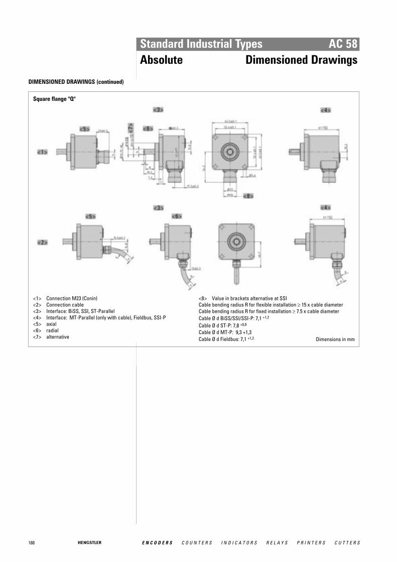
188 E N C O D E R S C O U N T E R S I N D I C A T O R S R E L A Y S P R I N T E R S C U T T E R S
Standard Industrial Types AC 58Absolute Dimensioned Drawings
DIMENSIONED DRAWINGS (continued)
Square flange "Q"
<1> Connection M23 (Conin)<2> Connection cable<3> Interface: BiSS, SSI, ST-Parallel<4> Interface: MT-Parallel (only with cable), Fieldbus, SSI-P<5> axial<6> radial<7> alternative
<8> Value in brackets alternative at SSICable bending radius R for flexible installation ≥ 15 x cable diameterCable bending radius R for fixed installation ≥ 7.5 x cable diameterCable Ø d BiSS/SSI/SSI-P: 7,1 +1,2
Cable Ø d ST-P: 7,8 +0,9
Cable Ø d MT-P: 9,3 +1,3Cable Ø d Fieldbus: 7,1 +1,2 Dimensions in mm
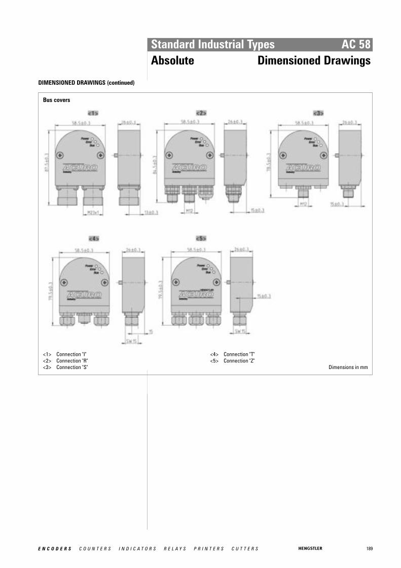
189E N C O D E R S C O U N T E R S I N D I C A T O R S R E L A Y S P R I N T E R S C U T T E R S
Standard Industrial Types AC 58Absolute Dimensioned Drawings
DIMENSIONED DRAWINGS (continued)
Bus covers
<1> Connection "I"<2> Connection "R"<3> Connection "S"
<4> Connection "T"<5> Connection "Z"
Dimensions in mm
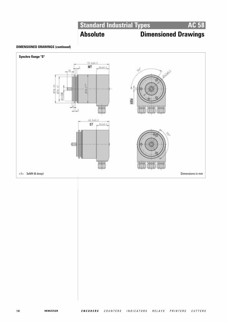
190 E N C O D E R S C O U N T E R S I N D I C A T O R S R E L A Y S P R I N T E R S C U T T E R S
Standard Industrial Types AC 58Absolute Dimensioned Drawings
DIMENSIONED DRAWINGS (continued)
Synchro flange "S"
<1> 3xM4 (6 deep) Dimensions in mm

191E N C O D E R S C O U N T E R S I N D I C A T O R S R E L A Y S P R I N T E R S C U T T E R S
Standard Industrial Types AC 58Absolute Dimensioned Drawings
DIMENSIONED DRAWINGS (continued)
Clamping flange "K"
Dim. Unit
Shaft Ø A 10 -0.01/-0.02 9.52 -0.01/-0.02 mm
Shaft code "2" "6"
<1> 3xM4 (6 deep)<2> 3xM3 (6 deep)
Dimensions in mm

192 E N C O D E R S C O U N T E R S I N D I C A T O R S R E L A Y S P R I N T E R S C U T T E R S
Standard Industrial Types AC 58Absolute Dimensioned Drawings
DIMENSIONED DRAWINGS (continued)
Hollow shaft "F"
Dim. Unit
Hollow shaft Ø A 10 +0.012 12 +0.012 9,52 +0.012 12,7 +0.012 mm
Connecting shaft Ø C 10 g7 12 g7 9,52 g7 12,7 g7 mm
Clamping ring Ø B 18 20 18 22 mm
L min 15 18 15 18 mm
L max 20 20 20 20 mm
Shaft code "2" "7" "6" "E"
L = Inside length of connection shaft
<1> Customer side
Dimensions in mm

193E N C O D E R S C O U N T E R S I N D I C A T O R S R E L A Y S P R I N T E R S C U T T E R S
Standard Industrial Types AC 58Absolute Dimensioned Drawings
DIMENSIONED DRAWINGS (continued)
Square flange "Q"
Dim. Unit
Shaft Ø A 10 -0.01/-0.02 9.52 -0.01/-0.02 mm
Shaft code "2" "6" Dimensions in mm

194 E N C O D E R S C O U N T E R S I N D I C A T O R S R E L A Y S P R I N T E R S C U T T E R S
Standard Industrial Types AC 110Absolute BiSS / SSI
� Same electrical performance as ACURO industry� Robust bearings for long life� Hollow shaft up to 50 mm� Absolute singleturn� Revolution 11-17 Bit� BiSS or SSI interface� Optional: Sine-Cosine 4096 increments� DC 5 or 10 - 30 V� Integrated diagnostic system
GENERAL INFORMATION HENGSTLER OPTOASIC Technology
The central Element of the ACURO AC110 is the latest Hengstler OptoAsic technology, whichoffers the following key benefits. • Outstanding reliability by reduced number of components and integrated diagnostics
systems • Aging compensation by integrated LED light regulation • Integrated monitoring of pollution, disk damage, LED lifetime and temperature
The ACURO AC110 is ideally suited for applications like: • Gearless drive • Gearless elevators • Industrial Machinery
TECHNICAL DATA mechanical
Housing diameter 110 mm
Shaft diameter 50 mm (Hub shaft)
Mounting of shaft Keyway, Rear clamping ring
Protection class shaft input (EN 60529)
IP50 or IP64
Protection class housing (EN 60529)
IP40 or IP64
Axial endplay of mounting shaft (hubshaft)
± 0.5 mm
Radial runout of mating shaft (hubshaft)
± 0.05 mm
Max. speed IP40: max. 3600 rpmIP50: max. 2000 rpmIP64: max. 1500 rpm
Torque 15 Ncm
Vibration resistance (DIN EN 60068-2-6)
100 m/s² (10 ... 500 Hz)
Shock resistance (DIN EN 60068-2-27)
1000 m/s² (6 ms)
Operating temperature -20 °C ... +70 °C
Storage temperature -50 °C ... +80 °C
Material shaft Stainless Steel / Aluminum, ceramic coated
Material housing Aluminum
Weight approx. 1000 g

195E N C O D E R S C O U N T E R S I N D I C A T O R S R E L A Y S P R I N T E R S C U T T E R S
Standard Industrial Types AC 110Absolute BiSS / SSI
TECHNICAL DATA mechanical (continued)
Connection Cable, radialCable 1.5 m with M23 connector (Conin), 12 pole, axial orradial
TECHNICAL DATA electrical
Supply voltage -5%/ 10% DC 5 VDC 10-30 V
Max. current w/o load 120 mA (ST)
Resolution singleturn 10 - 17 Bit
Output code Binary, Gray
Drives Clock and Data / RS422
Incremental signals optional Sinus-Cosinus 1 Vpp
Number of pulses 4096
3dB limiting frequency 500 kHz
Alarm output Alarm bit (SSI Option), warning and alarm bit (BiSS)
RECOMMENDED DATA TRANSFER RATEbei SSI
The max. data transfer rate depends on the cable length. For Clock / Clock and Data / Dataplease use twisted pairs. Use shielded cable.
Cable length Frequency
< 50 m < 400 kHz
< 100 m < 300 kHz
< 200 m < 200 kHz
< 400 m < 100 kHz
ELECTRICAL CONNECTIONSCable / Cable with M23 connector (Conin), 12 pole
Colour cable Cable connector
Signal
brown 4 1 0 V (supply voltage)
pink 2 Data
yellow 3 Clock
4 N.C.
blue 5 Direction 1
6 N.C.
7 N.C.
white 4 8 DC 5 V 3 / DC 10 - 30 V
9 N.C.
grey 10 Data
green 11 Clock
black 12 0 V-signal output 2
Screen Shielded with housing 1 Direction: + UB or unconnected = ascending code values with rotation cw
0 V = descending code values with rotation cw 2 Connected with 0 V in the encoder. Use this output to lay Direction on logical "0"
if required. 3 Notice: when supply voltage = DC 5V � max. cable length 10 m 4 Use only thin wires 0.14 mm 2
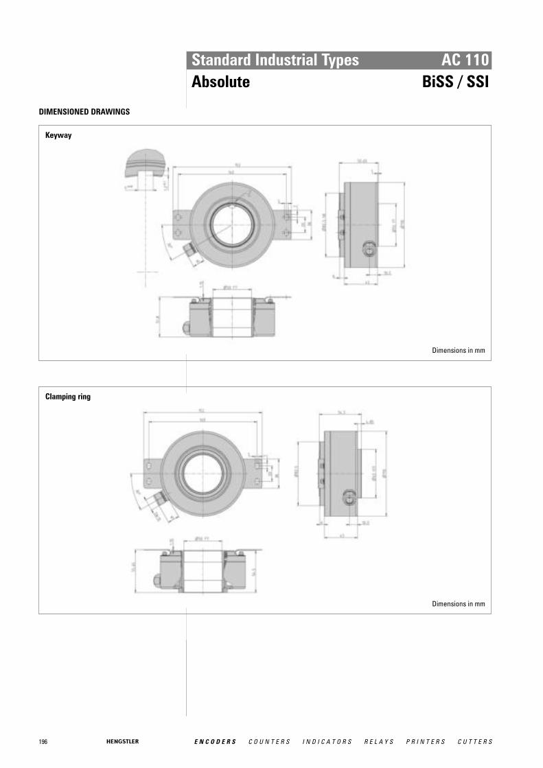
196 E N C O D E R S C O U N T E R S I N D I C A T O R S R E L A Y S P R I N T E R S C U T T E R S
Standard Industrial Types AC 110Absolute BiSS / SSI
DIMENSIONED DRAWINGS
Keyway
Dimensions in mm
Clamping ring
Dimensions in mm

197E N C O D E R S C O U N T E R S I N D I C A T O R S R E L A Y S P R I N T E R S C U T T E R S
Standard Industrial Types AC 110Absolute BiSS / SSI
ORDERING INFORMATION
Type Resolution 1 Supply voltage2
Shaft Protec-tion
Springtether
Interface Connection
AC110 0010 10 Bit ST0012 12 Bit ST0013 13 Bit ST0014 14 Bit ST0017 17 Bit ST
A DC 5 VE DC 10 - 30 V
K50 Keyway (4x1,2)/ 50 mm
H50 Clamping ring /50 mm
0 IP401 IP504 IP64
O Withouttether
B Withtether
BI BiSSSB SSI binarySG SSI Gray
B Cable, radialB-D 1.5 m cable
with M23connector(Conin), 12 pole
1 When resolution > 14 Bit: max. clock frequency 178´kHz2 Max. cable length for DC 5 V: 10 m
ORDERING INFORMATION Selection of cable length
Versions with cable outlet (connection A, B, E or F) are available with various lengths ofcable. To order your desired cable length, please add the respective code to the end ofyour ordering code. Further cable lengths on request.
Code Cable length
without code 1.5 m
-D0 3 m
-F0 5 m
-K0 10 m
-P0 15 m
-U0 20 m
-V0 25 m
ACCESSORIES see chapter "Accessories”, starting page 322
198 E N C O D E R S C O U N T E R S I N D I C A T O R S R E L A Y S P R I N T E R S C U T T E R S
Stainless Industrial Types
The absolute encoder line ACURO® and incremental encoder line“RI” are available as stainless steel encoders under AC59 or AC61for absolute encoders and RI59 for incremental encoder.
The absolute stainless steel encoders are available in the versions AC59 and AC61:
■ AC59: drawn stainless steel housing, together with cable outlet,no access to control elements
■ AC61: machined housing, possible with cable or bus cover,access to control elements (DIP switch, reset switch)
Available interfaces: SSI, BiSS, SSI-P, Parallel, Profibus,CAN layer2, CANopen, DeviceNet, Interbus
The incremental stainless steel encoder is available in the versionRI59:
■ RI59: drawn stainless steel housing with cable outlet
Examples of applications for stainless steel encoders:
■ oil field applications■ packaging machines■ food & beverage■ ship equipment■ other offshore applications

199E N C O D E R S C O U N T E R S I N D I C A T O R S R E L A Y S P R I N T E R S C U T T E R S
Stainless Industrial Types RI 59Incremental
� Stainless steel encoder with high protection class� High corrosion resistance� Use in the area of food production� Applications: packing machines, bottling machines, washing plants, mixers, cranes,
hoists, marine outfitters
NUMBER OF PULSES 1 / 2 / 3 / 4 / 5 / 10 / 15 / 20 / 25 / 30 / 35 / 40 / 45 / 50 / 60 / 64 / 70 / 72 / 80 / 100 / 125 / 128 / 144/ 150 / 180 / 200 / 230 / 250 / 256 / 300 / 314 / 350 / 360 / 375 / 400 / 460 / 480 / 500 / 512 / 600 /625 / 635 /720 / 900 / 1000 / 1024 / 1200 / 1250 / 1500 / 1600 / 1800 / 2000 / 2048 / 2500 / 3000 /3480 / 3600 / 3750 / 3968 / 4000 / 4096 / 4800 / 5000 / 5400 / 6000 / 7200 / 7680 / 8000 / 8192 /9000 / 10000 Other number of pulses on request Preferably available versions are printed in bold type.
TECHNICAL DATA mechanical
Housing diameter 58 mm
Shaft diameter 9.52 mm / 10 mm (Solid shaft)
Flange (Mounting of housing)
Square flange 63.5 mm
Protection class shaft input (EN 60529)
IP67
Protection class housing (EN 60529)
IP67
Shaft load axial / radial 40 N / 60 N
Max. speed max. 10 000 rpm
Torque ≤ 1 Ncm
Moment of inertia approx. 20 gcm²
Vibration resistance (DIN EN 60068-2-6)
100 m/s² (10 ... 2000 Hz)
Shock resistance (DIN EN 60068-2-27)
1000 m/s² (6 ms)
Operating temperature -10 °C ... +70 °C
Storage temperature -25 °C ... +85 °C
Material housing Stainless Steel
Weight approx. 620 g
Connection Cable, axial or radial
TECHNICAL DATA electrical
General design as per DIN VDE 0160, protection class III, contaminationlevel 2, overvoltage class II
Supply voltage 1 RS422 + Sense (T): DC 5 V ±10 % RS422 + Alarm (R): ± 10% DC 5 V or DC 10 - 30 VPush-pull (K), Push-pull antivalent (I): DC 10-30 V
Max. current w/o load 40 mA (DC 5 V), 60 mA (DC 10 V), 30 mA (DC 24 V)
Max. pulse frequency RS422: 300 kHzPush-pull: 200 kHz
Standard output versions 2
RS422 + Alarm (R): A, B, N, A, B, N, AlarmRS422 + Sense (T): A, B, N, A, B, N, SensePush-pull (K): A, B, N, AlarmPush-pull complementary (I): A, B, N, A, B, N, Alarm
Stai
nles
sIn
dust
rial
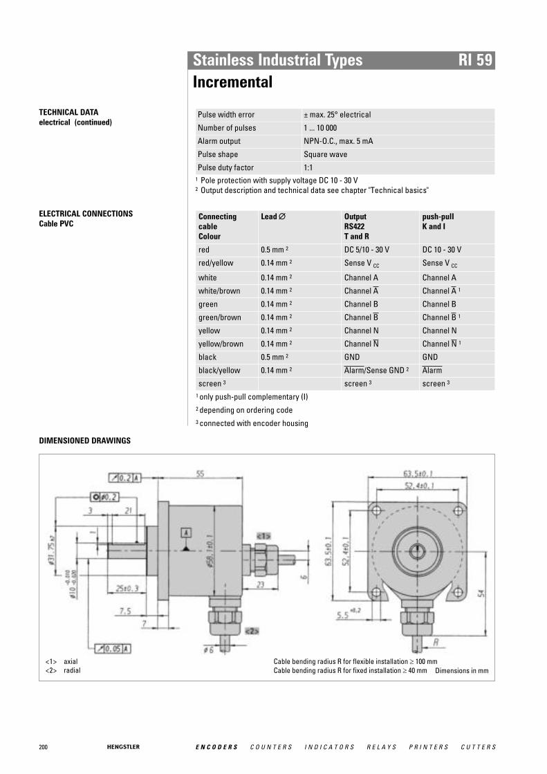
200 E N C O D E R S C O U N T E R S I N D I C A T O R S R E L A Y S P R I N T E R S C U T T E R S
Stainless Industrial Types RI 59Incremental
TECHNICAL DATA electrical (continued)
Pulse width error ± max. 25° electrical
Number of pulses 1 ... 10 000
Alarm output NPN-O.C., max. 5 mA
Pulse shape Square wave
Pulse duty factor 1:11 Pole protection with supply voltage DC 10 - 30 V2 Output description and technical data see chapter "Technical basics"
ELECTRICAL CONNECTIONSCable PVC
Connectingcable Colour
Lead ∅∅ Output RS422 T and R
push-pull K and I
red 0.5 mm 2 DC 5/10 - 30 V DC 10 - 30 V
red/yellow 0.14 mm 2 Sense V CC Sense V CC
white 0.14 mm 2 Channel A Channel A
white/brown 0.14 mm 2 Channel A Channel A 1
green 0.14 mm 2 Channel B Channel B
green/brown 0.14 mm 2 Channel B Channel B 1
yellow 0.14 mm 2 Channel N Channel N
yellow/brown 0.14 mm 2 Channel N Channel N 1
black 0.5 mm 2 GND GND
black/yellow 0.14 mm 2 Alarm/Sense GND 2 Alarm
screen 3 screen 3 screen 3
1 only push-pull complementary (I) 2 depending on ordering code 3 connected with encoder housing
DIMENSIONED DRAWINGS
<1> axial<2> radial
Cable bending radius R for flexible installation ≥ 100 mmCable bending radius R for fixed installation ≥ 40 mm Dimensions in mm
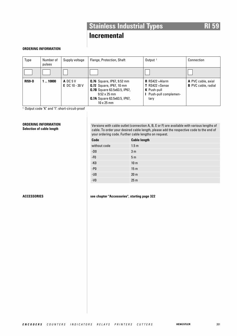
201E N C O D E R S C O U N T E R S I N D I C A T O R S R E L A Y S P R I N T E R S C U T T E R S
Stainless Industrial Types RI 59Incremental
ORDERING INFORMATION
Type Number ofpulses
Supply voltage Flange, Protection, Shaft Output 1 Connection
RI59-O 1 ... 10000 A DC 5 VE DC 10 - 30 V
Q.76 Square, IP67, 9.52 mmQ.72 Square, IP67, 10 mmQ.7B Square 63.5x63.5, IP67,
9.52 x 25 mmQ.7A Square 63.5x63.5, IP67,
10 x 25 mm
R RS422 +AlarmT RS422 +SenseK Push-pullI Push-pull complemen-
tary
A PVC cable, axialB PVC cable, radial
1 Output code "K" and "I": short-circuit-proof
ORDERING INFORMATION Selection of cable length
Versions with cable outlet (connection A, B, E or F) are available with various lengths ofcable. To order your desired cable length, please add the respective code to the end ofyour ordering code. Further cable lengths on request.
Code Cable length
without code 1.5 m
-D0 3 m
-F0 5 m
-K0 10 m
-P0 15 m
-U0 20 m
-V0 25 m
ACCESSORIES see chapter "Accessories", starting page 322
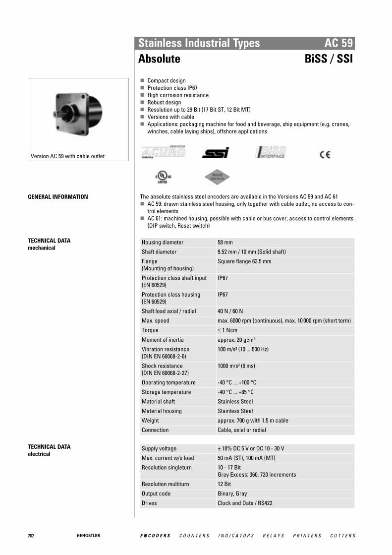
202 E N C O D E R S C O U N T E R S I N D I C A T O R S R E L A Y S P R I N T E R S C U T T E R S
Stainless Industrial Types AC 59Absolute BiSS / SSI
Version AC 59 with cable outlet
� Compact design� Protection class IP67� High corrosion resistance� Robust design� Resolution up to 29 Bit (17 Bit ST, 12 Bit MT)� Versions with cable� Applications: packaging machine for food and beverage, ship equipment (e.g. cranes,
winches, cable laying ships), offshore applications
GENERAL INFORMATION The absolute stainless steel encoders are available in the Versions AC 59 and AC 61 � AC 59: drawn stainless steel housing, only together with cable outlet, no access to con-
trol elements � AC 61: machined housing, possible with cable or bus cover, access to control elements
(DIP switch, Reset switch)
TECHNICAL DATA mechanical
Housing diameter 58 mm
Shaft diameter 9.52 mm / 10 mm (Solid shaft)
Flange (Mounting of housing)
Square flange 63.5 mm
Protection class shaft input (EN 60529)
IP67
Protection class housing (EN 60529)
IP67
Shaft load axial / radial 40 N / 60 N
Max. speed max. 6000 rpm (continuous), max. 10 000 rpm (short term)
Torque ≤ 1 Ncm
Moment of inertia approx. 20 gcm²
Vibration resistance (DIN EN 60068-2-6)
100 m/s² (10 ... 500 Hz)
Shock resistance (DIN EN 60068-2-27)
1000 m/s² (6 ms)
Operating temperature -40 °C ... +100 °C
Storage temperature -40 °C ... +85 °C
Material shaft Stainless Steel
Material housing Stainless Steel
Weight approx. 700 g with 1.5 m cable
Connection Cable, axial or radial
TECHNICAL DATA electrical
Supply voltage ± 10% DC 5 V or DC 10 - 30 V
Max. current w/o load 50 mA (ST), 100 mA (MT)
Resolution singleturn 10 - 17 BitGray Excess: 360, 720 increments
Resolution multiturn 12 Bit
Output code Binary, Gray
Drives Clock and Data / RS422
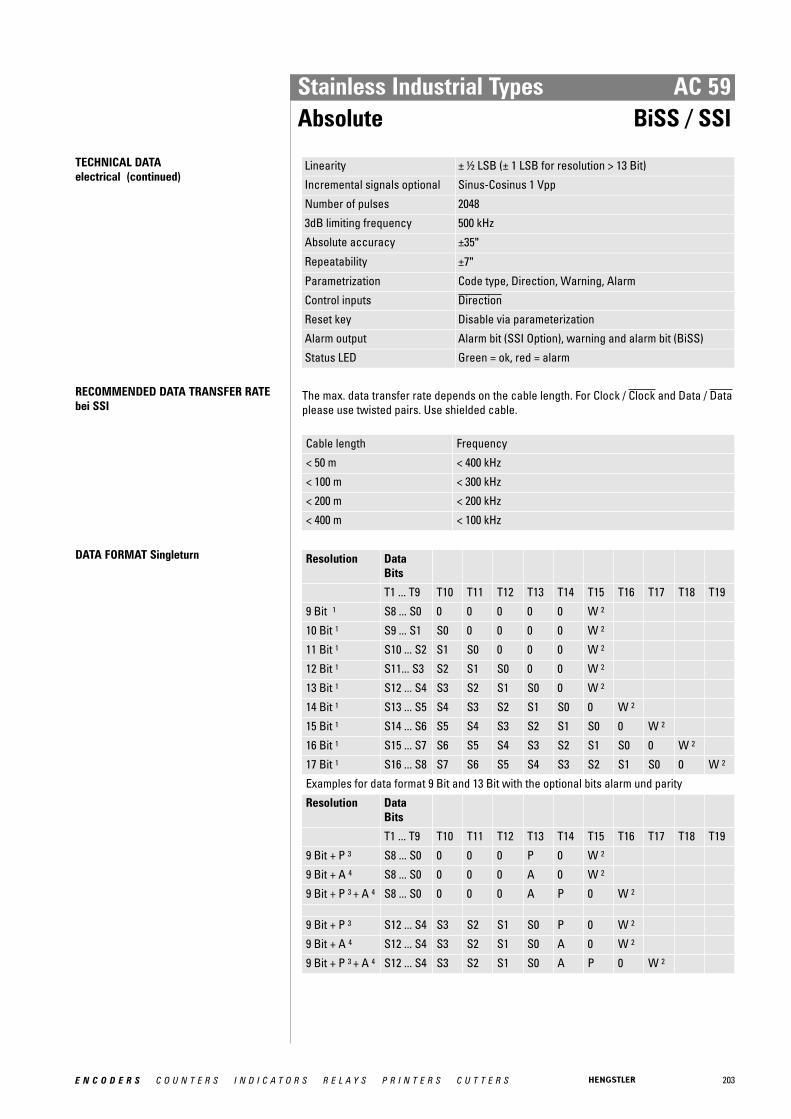
203E N C O D E R S C O U N T E R S I N D I C A T O R S R E L A Y S P R I N T E R S C U T T E R S
Stainless Industrial Types AC 59Absolute BiSS / SSI
TECHNICAL DATA electrical (continued)
Linearity ± ½ LSB (± 1 LSB for resolution > 13 Bit)
Incremental signals optional Sinus-Cosinus 1 Vpp
Number of pulses 2048
3dB limiting frequency 500 kHz
Absolute accuracy ±35"
Repeatability ±7"
Parametrization Code type, Direction, Warning, Alarm
Control inputs Direction
Reset key Disable via parameterization
Alarm output Alarm bit (SSI Option), warning and alarm bit (BiSS)
Status LED Green = ok, red = alarm
RECOMMENDED DATA TRANSFER RATEbei SSI
The max. data transfer rate depends on the cable length. For Clock / Clock and Data / Dataplease use twisted pairs. Use shielded cable.
Cable length Frequency
< 50 m < 400 kHz
< 100 m < 300 kHz
< 200 m < 200 kHz
< 400 m < 100 kHz
DATA FORMAT Singleturn Resolution DataBits
T1 ... T9 T10 T11 T12 T13 T14 T15 T16 T17 T18 T19
9 Bit 1 S8 ... S0 0 0 0 0 0 W 2
10 Bit 1 S9 ... S1 S0 0 0 0 0 W 2
11 Bit 1 S10 ... S2 S1 S0 0 0 0 W 2
12 Bit 1 S11... S3 S2 S1 S0 0 0 W 2
13 Bit 1 S12 ... S4 S3 S2 S1 S0 0 W 2
14 Bit 1 S13 ... S5 S4 S3 S2 S1 S0 0 W 2
15 Bit 1 S14 ... S6 S5 S4 S3 S2 S1 S0 0 W 2
16 Bit 1 S15 ... S7 S6 S5 S4 S3 S2 S1 S0 0 W 2
17 Bit 1 S16 ... S8 S7 S6 S5 S4 S3 S2 S1 S0 0 W 2
Examples for data format 9 Bit and 13 Bit with the optional bits alarm und parity
Resolution DataBits
T1 ... T9 T10 T11 T12 T13 T14 T15 T16 T17 T18 T19
9 Bit + P 3 S8 ... S0 0 0 0 P 0 W 2
9 Bit + A 4 S8 ... S0 0 0 0 A 0 W 2
9 Bit + P 3 + A 4 S8 ... S0 0 0 0 A P 0 W 2
9 Bit + P 3 S12 ... S4 S3 S2 S1 S0 P 0 W 2
9 Bit + A 4 S12 ... S4 S3 S2 S1 S0 A 0 W 2
9 Bit + P 3 + A 4 S12 ... S4 S3 S2 S1 S0 A P 0 W 2
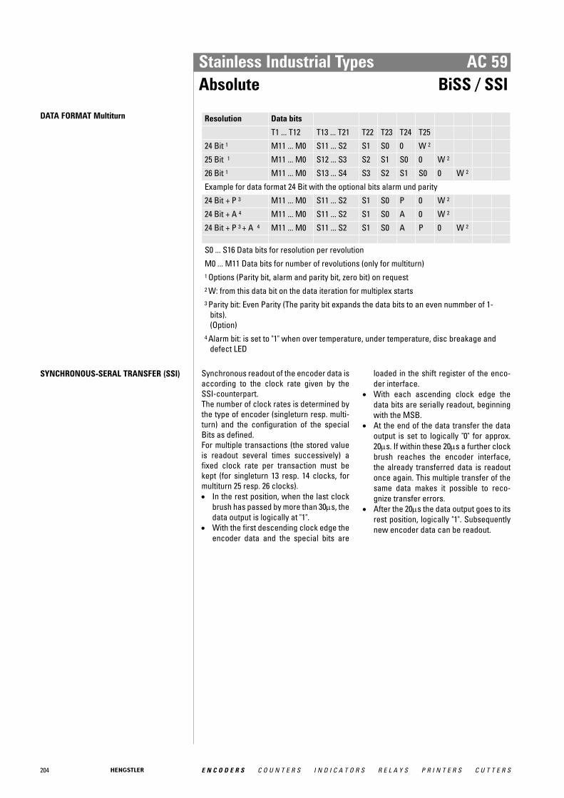
204 E N C O D E R S C O U N T E R S I N D I C A T O R S R E L A Y S P R I N T E R S C U T T E R S
Stainless Industrial Types AC 59Absolute BiSS / SSI
DATA FORMAT Multiturn Resolution Data bits
T1 ... T12 T13 ... T21 T22 T23 T24 T25
24 Bit 1 M11 ... M0 S11 ... S2 S1 S0 0 W 2
25 Bit 1 M11 ... M0 S12 ... S3 S2 S1 S0 0 W 2
26 Bit 1 M11 ... M0 S13 ... S4 S3 S2 S1 S0 0 W 2
Example for data format 24 Bit with the optional bits alarm und parity
24 Bit + P 3 M11 ... M0 S11 ... S2 S1 S0 P 0 W 2
24 Bit + A 4 M11 ... M0 S11 ... S2 S1 S0 A 0 W 2
24 Bit + P 3 + A 4 M11 ... M0 S11 ... S2 S1 S0 A P 0 W 2
S0 ... S16 Data bits for resolution per revolution
M0 ... M11 Data bits for number of revolutions (only for multiturn) 1 Options (Parity bit, alarm and parity bit, zero bit) on request 2 W: from this data bit on the data iteration for multiplex starts 3 Parity bit: Even Parity (The parity bit expands the data bits to an even nummber of 1-
bits). (Option)
4 Alarm bit: is set to "1" when over temperature, under temperature, disc breakage anddefect LED
SYNCHRONOUS-SERAL TRANSFER (SSI) Synchronous readout of the encoder data isaccording to the clock rate given by theSSI-counterpart. The number of clock rates is determined bythe type of encoder (singleturn resp. multi-turn) and the configuration of the specialBits as defined. For multiple transactions (the stored valueis readout several times successively) afixed clock rate per transaction must bekept (for singleturn 13 resp. 14 clocks, formultiturn 25 resp. 26 clocks). • In the rest position, when the last clock
brush has passed by more than 30μs, thedata output is logically at "1".
• With the first descending clock edge theencoder data and the special bits are
loaded in the shift register of the enco-der interface.
• With each ascending clock edge thedata bits are serially readout, beginningwith the MSB.
• At the end of the data transfer the dataoutput is set to logically "0" for approx.20μs. If within these 20μs a further clockbrush reaches the encoder interface,the already transferred data is readoutonce again. This multiple transfer of thesame data makes it possible to reco-gnize transfer errors.
• After the 20μs the data output goes to itsrest position, logically "1". Subsequentlynew encoder data can be readout.

205E N C O D E R S C O U N T E R S I N D I C A T O R S R E L A Y S P R I N T E R S C U T T E R S
Stainless Industrial Types AC 59Absolute BiSS / SSI
ELECTRICAL CONNECTIONS12 pole / cable Interface SC, BC
Cable Signal
brown 2 0 V (supply voltage)
pink Data
yellow Clock
white/green A+
blue Direction 1
red/blue B+
brown/green A-
white 2 DC 5/10 - 30 V
grey/pink B-
grey Data
green Clock
black Sense 1 Direction : +UB or unconnected = ascending code values with rotation cw
0 V = descending code values with rotation cw 2 use only the thin wires (∅ = 0,14 mm)
DIMENSIONED DRAWINGS see chapter "Dimensioned drawings AC 59 / AC 61", starting page 232
ORDERING INFORMATION
Type Resolution 1, 2 Supply voltage Flange, Protection, Shaft Interface Connection
AC59 0010 10 Bit ST0012 12 Bit ST0013 13 Bit ST0014 14 Bit ST0017 17 Bit ST0360 360 increments ST0720 720 increments ST1212 12 Bit MT + 12 Bit ST1213 12 Bit MT + 13 Bit ST1214 12 Bit MT + 14 Bit ST
(BiSS)1217 12 Bit MT + 17 Bit ST
(BiSS)
A DC 5 VE DC 10 - 30 V
Q.76 Square, IP67, 9.52 mmQ.72 Square, IP67, 10 mm
BI BiSSBC BiSS (+SinCos
1Vpp)SB SSI binarySG SSI GraySC SSI Gray
(+SinCos1Vpp)
A Cable, axialB Cable, radial
1 Resolution 360 increments ST with Offset 76 (value range 76...435)2 Resolution 720 increments ST with Offset 152 (value range 152...871)
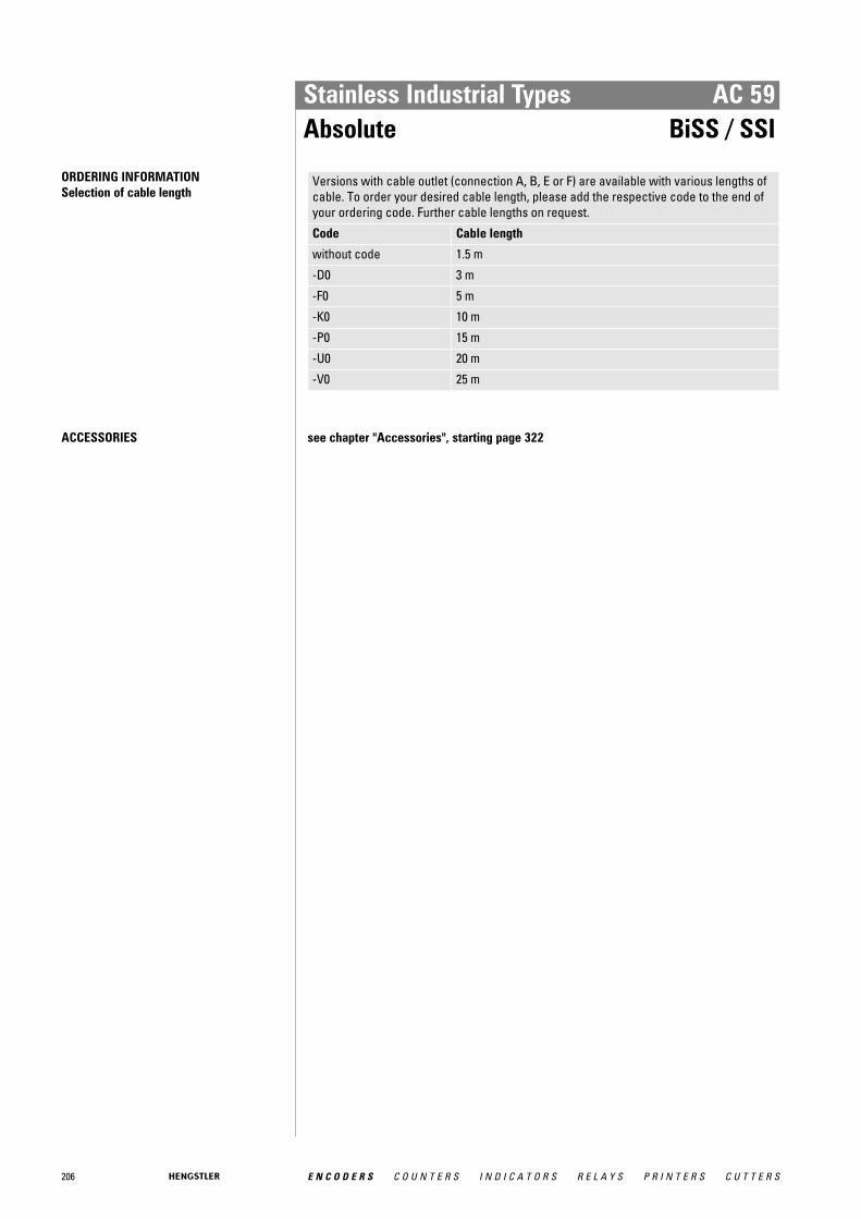
206 E N C O D E R S C O U N T E R S I N D I C A T O R S R E L A Y S P R I N T E R S C U T T E R S
Stainless Industrial Types AC 59Absolute BiSS / SSI
ORDERING INFORMATION Selection of cable length
Versions with cable outlet (connection A, B, E or F) are available with various lengths ofcable. To order your desired cable length, please add the respective code to the end ofyour ordering code. Further cable lengths on request.
Code Cable length
without code 1.5 m
-D0 3 m
-F0 5 m
-K0 10 m
-P0 15 m
-U0 20 m
-V0 25 m
ACCESSORIES see chapter "Accessories", starting page 322

207E N C O D E R S C O U N T E R S I N D I C A T O R S R E L A Y S P R I N T E R S C U T T E R S
Stainless Industrial Types AC 59 / AC 61Absolute Parallel
Version AC 59 with cable outlet
Version AC 61 with bus cover
� Compact design� Protection class IP67� High corrosion resistance� Robust design� Resolution up to 26 Bit (14 Bit ST, 12 Bit MT)� Gray or Binary code� Encoder monitoring� Output Tristate short circuit-proof� Applications: packaging machine for food and beverage, ship equipment (e.g. cranes,
winches, cable laying ships), offshore applications
GENERAL INFORMATION The absolute stainless steel encoders with parallel interface are available in the Versions AC59 and AC 61. � AC 59: drawn stainless steel housing, only together with Singleturn � AC 61: machined housing
TECHNICAL DATA mechanical
Housing diameter AC 59: 58 mmAC 61: 61.5 mm
Shaft diameter 9.52 mm / 10 mm (Solid shaft)
Flange (Mounting of housing)
Square flange 63.5 mm
Protection class shaft input (EN 60529)
IP67
Protection class housing (EN 60529)
IP67
Shaft load axial / radial 40 N / 60 N
Max. speed max. 6000 rpm (continuous), max. 10 000 rpm (short term)
Torque ≤ 1 Ncm
Moment of inertia approx. 20 gcm²
Vibration resistance (DIN EN 60068-2-6)
100 m/s² (10 ... 500 Hz)
Shock resistance (DIN EN 60068-2-27)
1000 m/s² (6 ms)
Operating temperature -40 °C ... +100 °C
Storage temperature -40 °C ... +85 °C
Material shaft Stainless Steel
Material housing Stainless Steel
Weight AC 59: approx. 700 g with 1.5 m cableAC 61: approx. 980 g with 1.5 m cable
Connection Cable, axial or radial
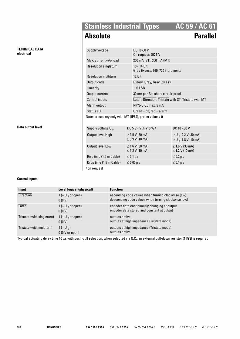
208 E N C O D E R S C O U N T E R S I N D I C A T O R S R E L A Y S P R I N T E R S C U T T E R S
Stainless Industrial Types AC 59 / AC 61Absolute Parallel
TECHNICAL DATA electrical
Supply voltage DC 10-30 VOn request: DC 5 V
Max. current w/o load 200 mA (ST), 300 mA (MT)
Resolution singleturn 10 - 14 BitGray Excess: 360, 720 increments
Resolution multiturn 12 Bit
Output code Binary, Gray, Gray Excess
Linearity ± ½ LSB
Output current 30 mA per Bit, short-circuit-proof
Control inputs Latch, Direction, Tristate with ST, Tristate with MT
Alarm output NPN-O.C., max. 5 mA
Status LED Green = ok, red = alarmNote: preset key only with MT (IP64), preset value = 0
Data output level Supply voltage U B DC 5 V - 5 % +10 % 1 DC 10 - 30 V
Output level High ≥ 3.5 V (30 mA) ≥ 3.9 V (10 mA)
≥ U B -2.2 V (30 mA) ≥ U B -1.8 V (10 mA)
Output level Low ≤ 1.6 V (30 mA) ≤ 1.2 V (10 mA)
≤ 1.6 V (30 mA) ≤ 1.2 V (10 mA)
Rise time (1.5 m Cable) ≤ 0.1 μs ≤ 0.2 μs
Drop time (1.5 m Cable) ≤ 0.05 μs ≤ 0.1 μs 1 on request
Control inputs
Input Level logical (physical) Function
Direction 1 (+ U B or open) 0 (0 V)
ascending code values when turning clockwise (cw) descending code values when turning clockwise (cw)
Latch 1 (+ U B or open) 0 (0 V)
encoder data continuously changing at output encoder data stored and constant at output
Tristate (with singleturn) 1 (+ U B or open) 0 (0 V)
outputs active outputs at high impedance (Tristate mode)
Tristate (with multiturn) 1 (+ U B ) 0 (0 V or open)
outputs at high impedance (Tristate mode) outputs active
Typical actuating delay time 10 μs with push-pull selection; when selected via O.C., an external pull-down resistor (1 KΩ) is required

209E N C O D E R S C O U N T E R S I N D I C A T O R S R E L A Y S P R I N T E R S C U T T E R S
Stainless Industrial Types AC 59 / AC 61Absolute Parallel
ELECTRICAL CONNECTIONSSingleturn, cable
Colour (PVC) 9 Bit / 360 incr. 10 Bit / 720 incr. 12 Bit 13 Bit 14 Bit
grey/pink N.C. N.C. N.C. N.C. SO (LSB)
brown/yellow N.C. N.C. N.C. SO (LSB) S1
brown/grey N.C. N.C. S0 (LSB) S1 S2
red/blue N.C. N.C. S1 S2 S3
violet N.C. S0 (LSB) S2 S3 S4
white/brown S0 (LSB) S1 S3 S4 S5
white/green S1 S2 S4 S5 S6
white/yellow S2 S3 S5 S6 S7
white/grey S3 S4 S6 S7 S8
white/pink S4 S5 S7 S8 S9
white/blue S5 S6 S8 S9 S10
white/red S6 S7 S9 S10 S11
white/black S7 S8 S10 S11 S12
brown/green S8 (MSB) S9 (MSB) S11 (MSB) S12 (MSB) S13 (MSB)
yellow Tristate S0...S8 Tristate S0...S9 Tristate S0...S11 Tristate S0...S12 Tristate S0...S13
pink Latch Latch Latch Latch Latch
green Direction Direction Direction Direction Direction
black 0 V 0 V 0 V 0 V 0 V
red DC 5 V/ 10-30 V DC 5 V/ 10-30 V DC 5 V/ 10-30 V DC 5 V/ 10-30 V DC 5 V/ 10-30 V
brown Alarm Alarm Alarm Alarm Alarm

210 E N C O D E R S C O U N T E R S I N D I C A T O R S R E L A Y S P R I N T E R S C U T T E R S
Stainless Industrial Types AC 59 / AC 61Absolute Parallel
ELECTRICAL CONNECTIONSMultiturn, cable (only AC 61 - Parallel)
Cable (TPE) 10 cm cable with Sub-D connector, 37pole
Cable (TPE) 10 cm cable with Sub-D connector, 37pole
Colour Pin Connection Colour Pin Connection
brown 2 S0 white/blue 14 M4 1
green 21 S1 brown/blue 33 M5 1
yellow 3 S2 white/red 15 M6 1
grey 22 S3 brown/red 34 M7 1
pink 4 S4 white/black 16 M8 2
violet 23 S5 brown/black 35 M9 2
grey/pink 5 S6 grey/green 17 M10 2
red/blue 24 S7 yellow/grey 36 M11 2
white/green 6 S8 pink/green 18 Alarm
brown/green 25 S9 yellow/pink 10 Direction
white/yellow 7 S10 green/blue 30 Latch
yellow/brown 26 S11 yellow/blue 12 Tristate
white/grey 8 M0 red (0.5mm 2 ) 13 DC 10-30 V
grey/brown 27 M1 white (0.5mm 2 ) 31 DC 10-30 V
white/pink 9 M2 blue (0.5mm 2 ) 1 0 V
pink/brown 28 M3 black (0.5mm 2 ) 20 0 V 1 N. C. with resolution 16 Bit (4 Bit MT) 2 N. C. with resolution 16 Bit or 20 Bit (4 or 8 Bit MT)
DIMENSIONED DRAWINGS see chapter "Dimensioned drawings AC 59 / AC 61", starting page 232

211E N C O D E R S C O U N T E R S I N D I C A T O R S R E L A Y S P R I N T E R S C U T T E R S
Stainless Industrial Types AC 59 / AC 61Absolute Parallel
ORDERING INFORMATION
Type Resolution 1, 2, 3 Supply voltage Flange, Protection, Shaft Interface Connection
AC59AC61
0010 10 Bit ST0012 12 Bit ST0013 13 Bit ST0014 14 Bit ST0017 17 Bit ST0360 360 increments ST0720 720 increments ST0412 4 Bit MT + 12 Bit ST
(AC 61)0812 8 Bit MT + 12 Bit ST
(AC 61)1212 12 Bit MT + 12 Bit ST
(AC 61)
A DC 5 VE DC 10 - 30 V
Q.76 Square, IP67, 9.52 mmQ.72 Square, IP67, 10 mm
PB Parallel binaryPG Parallel Gray
A Cable, axialB Cable, radial
1 Resolution 360 increments ST with Offset 76 (value range 76...435)2 Resolution 720 increments ST with Offset 152 (value range 152...871)3 AC59 only with ST (only AC 59)
ORDERING INFORMATION Selection of cable length
Versions with cable outlet (connection A, B, E or F) are available with various lengths ofcable. To order your desired cable length, please add the respective code to the end ofyour ordering code. Further cable lengths on request.
Code Cable length
without code 1.5 m
-D0 3 m
-F0 5 m
-K0 10 m
-P0 15 m
-U0 20 m
-V0 25 m
ACCESSORIES see chapter "Accessories", starting page 322

212 E N C O D E R S C O U N T E R S I N D I C A T O R S R E L A Y S P R I N T E R S C U T T E R S
Stainless Industrial Types AC 61Absolute Profibus
Version AC 61 with bus cover
� Compact design� Protection class IP67� High corrosion resistance� Robust design� Resolution up to 26 Bit (14 Bit ST, 12 Bit MT)� Bus cover� Programmable: Resolution, Preset, Direction� Output of speed, acceleration� Applications: packaging machine for food and beverage, ship equipment (e.g. cranes,
winches, cable laying ships), offshore applications
GENERAL INFORMATION The absolute stainless steel encoders are available in the Versions AC 59 and AC 61. � AC 59: drawn stainless steel housing, only together with cable outlet, no access to con-
trol elements � AC 61: machined housing, possible with cable or bus cover, access to control elements
(DIP switch, Reset switch)
TECHNICAL DATA mechanical
Housing diameter 61.5 mm
Shaft diameter 9.52 mm / 10 mm (Solid shaft)
Flange (Mounting of housing)
Square flange 63.5 mm
Protection class shaft input (EN 60529)
IP67
Protection class housing (EN 60529)
IP67
Shaft load axial / radial 40 N / 60 N
Max. speed max. 6000 rpm (continuous), max. 10 000 rpm (short term)
Torque ≤ 1 Ncm
Moment of inertia approx. 20 gcm²
Vibration resistance (DIN EN 60068-2-6)
100 m/s² (10 ... 500 Hz)
Shock resistance (DIN EN 60068-2-27)
1000 m/s² (6 ms)
Operating temperature -40 °C ... +85 °C
Storage temperature -40 °C ... +85 °C
Material shaft Stainless Steel
Material housing Stainless Steel
Weight approx. 1180 g
Connection Bus cover with 3 sealed cable exits
TECHNICAL DATA electrical
General design as per DIN EN 61010-1, protection class III, contamina-tion level 2, overvoltage class II
Supply voltage DC 10-30 V
Max. current w/o load 220 mA (ST), 250 mA (MT)
EMC EN 61326: Class A
Resolution singleturn 10 - 14 Bit
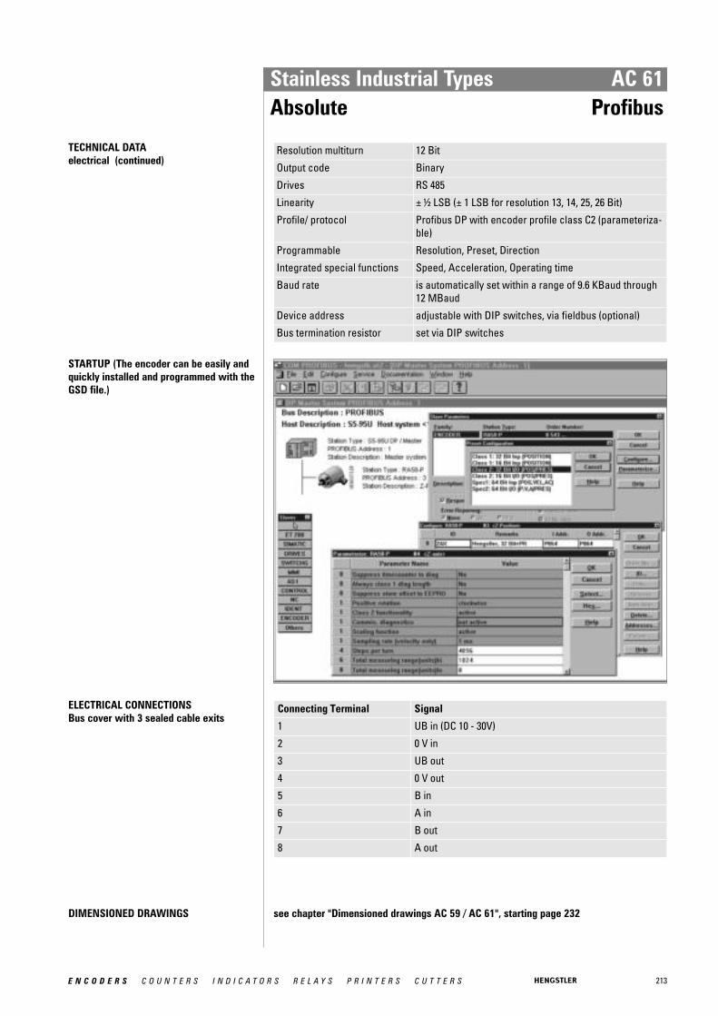
213E N C O D E R S C O U N T E R S I N D I C A T O R S R E L A Y S P R I N T E R S C U T T E R S
Stainless Industrial Types AC 61Absolute Profibus
TECHNICAL DATA electrical (continued)
Resolution multiturn 12 Bit
Output code Binary
Drives RS 485
Linearity ± ½ LSB (± 1 LSB for resolution 13, 14, 25, 26 Bit)
Profile/ protocol Profibus DP with encoder profile class C2 (parameteriza-ble)
Programmable Resolution, Preset, Direction
Integrated special functions Speed, Acceleration, Operating time
Baud rate is automatically set within a range of 9.6 KBaud through12 MBaud
Device address adjustable with DIP switches, via fieldbus (optional)
Bus termination resistor set via DIP switches
STARTUP (The encoder can be easily andquickly installed and programmed with theGSD file.)
ELECTRICAL CONNECTIONSBus cover with 3 sealed cable exits
Connecting Terminal Signal
1 UB in (DC 10 - 30V)
2 0 V in
3 UB out
4 0 V out
5 B in
6 A in
7 B out
8 A out
DIMENSIONED DRAWINGS see chapter "Dimensioned drawings AC 59 / AC 61", starting page 232

214 E N C O D E R S C O U N T E R S I N D I C A T O R S R E L A Y S P R I N T E R S C U T T E R S
Stainless Industrial Types AC 61Absolute Profibus
ORDERING INFORMATION
Type Resolution Supply voltage Flange, Protection, Shaft Interface Connection
AC61 0010 10 Bit ST0012 12 Bit ST0013 13 Bit ST0014 14 Bit ST1212 12 Bit MT + 12 Bit ST1213 12 Bit MT + 13 Bit ST1214 12 Bit MT + 14 Bit ST
E DC 10 - 30 V Q.76 Square, IP67, 9.52 mmQ.72 Square, IP67, 10 mm
DP Profibus Z Bus cover with 3sealed cable exits
ACCESSORIES see chapter "Accessories", starting page 322
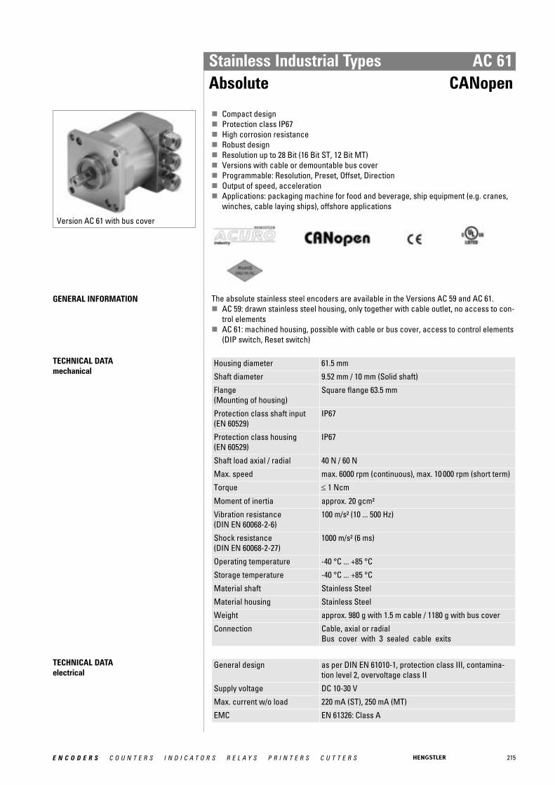
215E N C O D E R S C O U N T E R S I N D I C A T O R S R E L A Y S P R I N T E R S C U T T E R S
Stainless Industrial Types AC 61Absolute CANopen
Version AC 61 with bus cover
� Compact design� Protection class IP67� High corrosion resistance� Robust design� Resolution up to 28 Bit (16 Bit ST, 12 Bit MT)� Versions with cable or demountable bus cover� Programmable: Resolution, Preset, Offset, Direction� Output of speed, acceleration� Applications: packaging machine for food and beverage, ship equipment (e.g. cranes,
winches, cable laying ships), offshore applications
GENERAL INFORMATION The absolute stainless steel encoders are available in the Versions AC 59 and AC 61. � AC 59: drawn stainless steel housing, only together with cable outlet, no access to con-
trol elements � AC 61: machined housing, possible with cable or bus cover, access to control elements
(DIP switch, Reset switch)
TECHNICAL DATA mechanical
Housing diameter 61.5 mm
Shaft diameter 9.52 mm / 10 mm (Solid shaft)
Flange (Mounting of housing)
Square flange 63.5 mm
Protection class shaft input (EN 60529)
IP67
Protection class housing (EN 60529)
IP67
Shaft load axial / radial 40 N / 60 N
Max. speed max. 6000 rpm (continuous), max. 10 000 rpm (short term)
Torque ≤ 1 Ncm
Moment of inertia approx. 20 gcm²
Vibration resistance (DIN EN 60068-2-6)
100 m/s² (10 ... 500 Hz)
Shock resistance (DIN EN 60068-2-27)
1000 m/s² (6 ms)
Operating temperature -40 °C ... +85 °C
Storage temperature -40 °C ... +85 °C
Material shaft Stainless Steel
Material housing Stainless Steel
Weight approx. 980 g with 1.5 m cable / 1180 g with bus cover
Connection Cable, axial or radialBus cover with 3 sealed cable exits
TECHNICAL DATA electrical
General design as per DIN EN 61010-1, protection class III, contamina-tion level 2, overvoltage class II
Supply voltage DC 10-30 V
Max. current w/o load 220 mA (ST), 250 mA (MT)
EMC EN 61326: Class A
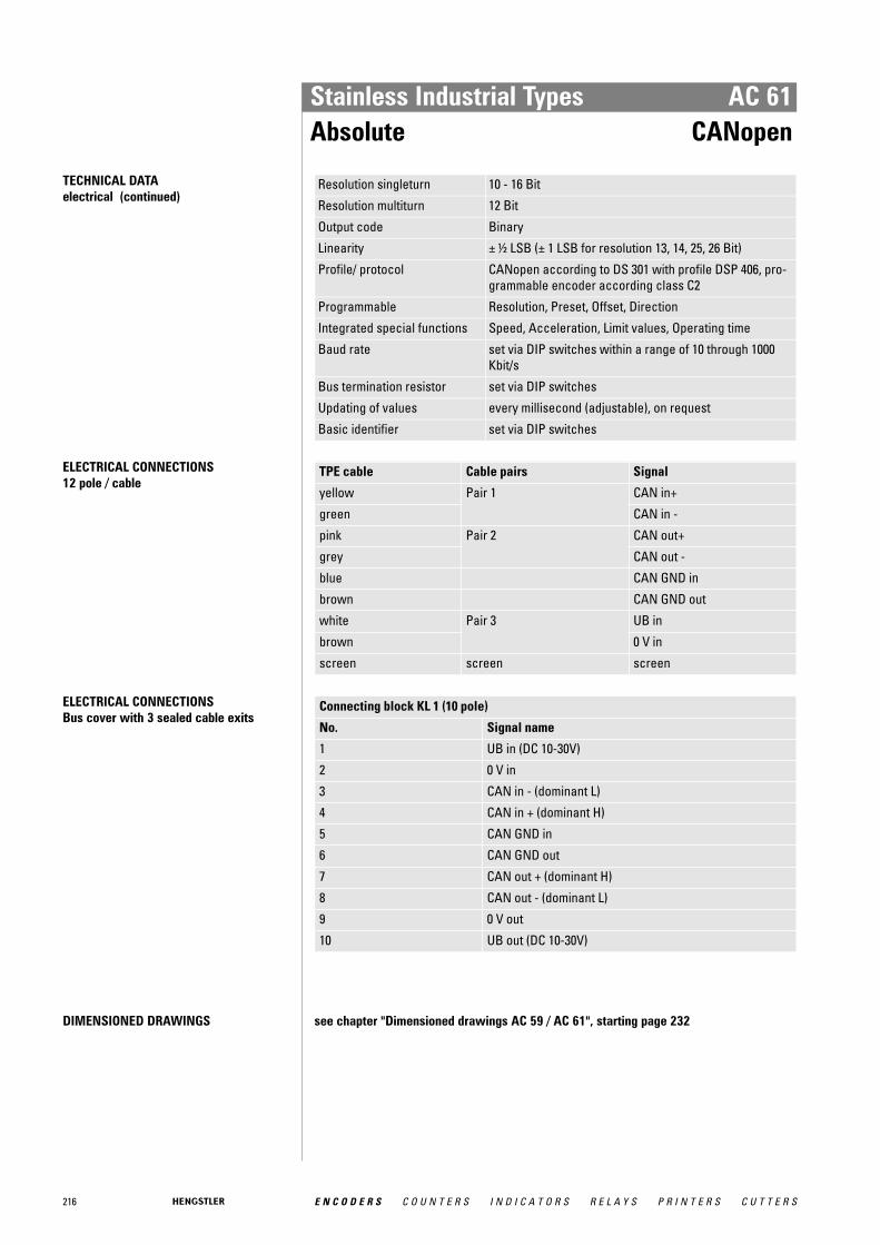
216 E N C O D E R S C O U N T E R S I N D I C A T O R S R E L A Y S P R I N T E R S C U T T E R S
Stainless Industrial Types AC 61Absolute CANopen
TECHNICAL DATA electrical (continued)
Resolution singleturn 10 - 16 Bit
Resolution multiturn 12 Bit
Output code Binary
Linearity ± ½ LSB (± 1 LSB for resolution 13, 14, 25, 26 Bit)
Profile/ protocol CANopen according to DS 301 with profile DSP 406, pro-grammable encoder according class C2
Programmable Resolution, Preset, Offset, Direction
Integrated special functions Speed, Acceleration, Limit values, Operating time
Baud rate set via DIP switches within a range of 10 through 1000Kbit/s
Bus termination resistor set via DIP switches
Updating of values every millisecond (adjustable), on request
Basic identifier set via DIP switches
ELECTRICAL CONNECTIONS12 pole / cable
TPE cable Cable pairs Signal
yellow Pair 1 CAN in+
green CAN in -
pink Pair 2 CAN out+
grey CAN out -
blue CAN GND in
brown CAN GND out
white Pair 3 UB in
brown 0 V in
screen screen screen
ELECTRICAL CONNECTIONSBus cover with 3 sealed cable exits
Connecting block KL 1 (10 pole)
No. Signal name
1 UB in (DC 10-30V)
2 0 V in
3 CAN in - (dominant L)
4 CAN in + (dominant H)
5 CAN GND in
6 CAN GND out
7 CAN out + (dominant H)
8 CAN out - (dominant L)
9 0 V out
10 UB out (DC 10-30V)
DIMENSIONED DRAWINGS see chapter "Dimensioned drawings AC 59 / AC 61", starting page 232
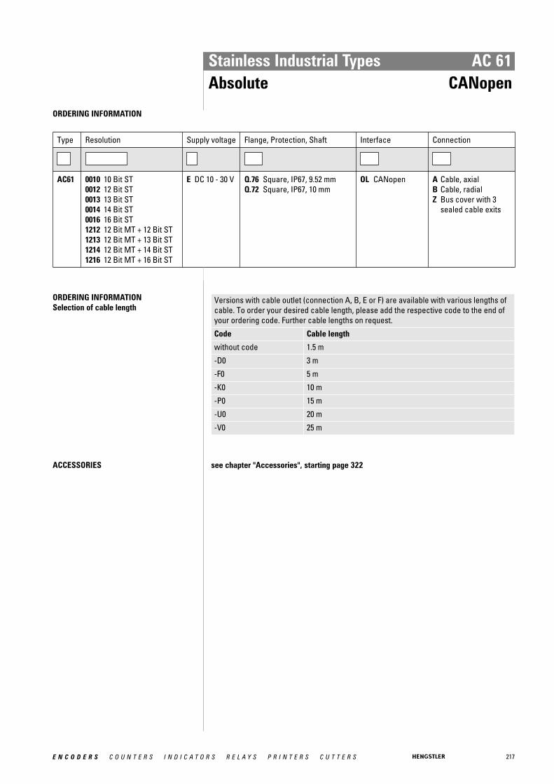
217E N C O D E R S C O U N T E R S I N D I C A T O R S R E L A Y S P R I N T E R S C U T T E R S
Stainless Industrial Types AC 61Absolute CANopen
ORDERING INFORMATION
Type Resolution Supply voltage Flange, Protection, Shaft Interface Connection
AC61 0010 10 Bit ST0012 12 Bit ST0013 13 Bit ST0014 14 Bit ST0016 16 Bit ST1212 12 Bit MT + 12 Bit ST1213 12 Bit MT + 13 Bit ST1214 12 Bit MT + 14 Bit ST1216 12 Bit MT + 16 Bit ST
E DC 10 - 30 V Q.76 Square, IP67, 9.52 mmQ.72 Square, IP67, 10 mm
OL CANopen A Cable, axialB Cable, radialZ Bus cover with 3
sealed cable exits
ORDERING INFORMATION Selection of cable length
Versions with cable outlet (connection A, B, E or F) are available with various lengths ofcable. To order your desired cable length, please add the respective code to the end ofyour ordering code. Further cable lengths on request.
Code Cable length
without code 1.5 m
-D0 3 m
-F0 5 m
-K0 10 m
-P0 15 m
-U0 20 m
-V0 25 m
ACCESSORIES see chapter "Accessories", starting page 322
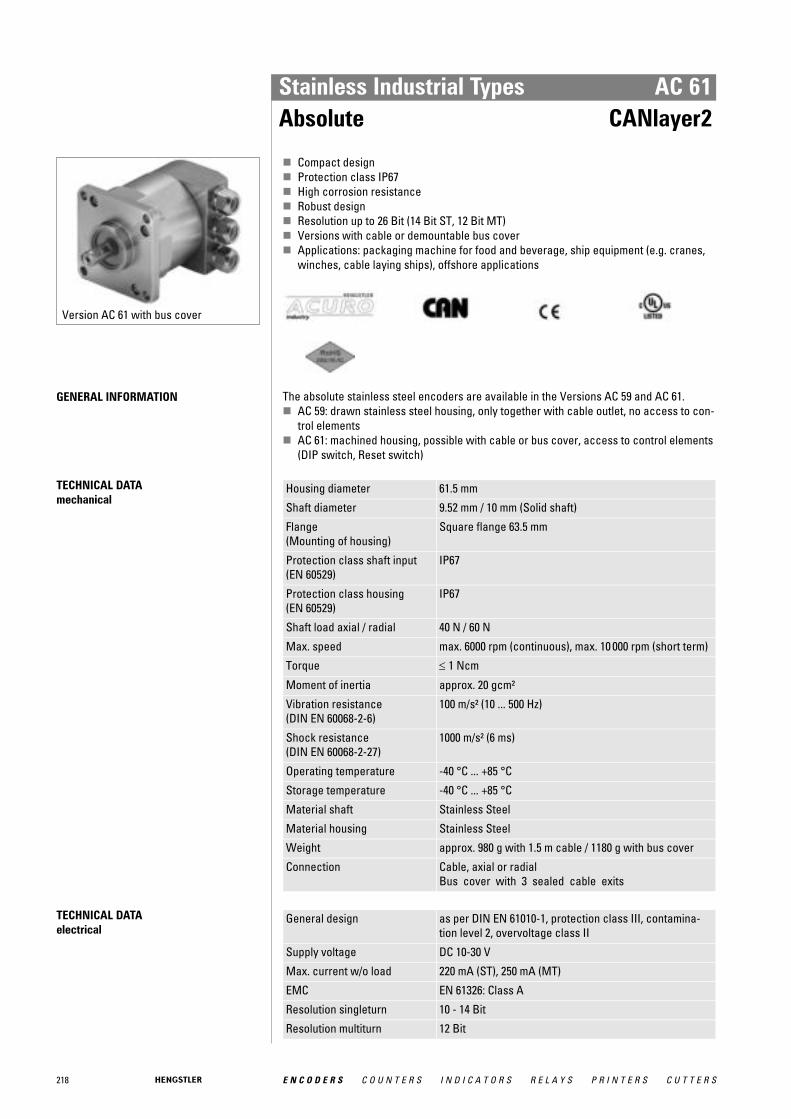
218 E N C O D E R S C O U N T E R S I N D I C A T O R S R E L A Y S P R I N T E R S C U T T E R S
Stainless Industrial Types AC 61Absolute CANlayer2
Version AC 61 with bus cover
� Compact design� Protection class IP67� High corrosion resistance� Robust design� Resolution up to 26 Bit (14 Bit ST, 12 Bit MT)� Versions with cable or demountable bus cover� Applications: packaging machine for food and beverage, ship equipment (e.g. cranes,
winches, cable laying ships), offshore applications
GENERAL INFORMATION The absolute stainless steel encoders are available in the Versions AC 59 and AC 61. � AC 59: drawn stainless steel housing, only together with cable outlet, no access to con-
trol elements � AC 61: machined housing, possible with cable or bus cover, access to control elements
(DIP switch, Reset switch)
TECHNICAL DATA mechanical
Housing diameter 61.5 mm
Shaft diameter 9.52 mm / 10 mm (Solid shaft)
Flange (Mounting of housing)
Square flange 63.5 mm
Protection class shaft input (EN 60529)
IP67
Protection class housing (EN 60529)
IP67
Shaft load axial / radial 40 N / 60 N
Max. speed max. 6000 rpm (continuous), max. 10 000 rpm (short term)
Torque ≤ 1 Ncm
Moment of inertia approx. 20 gcm²
Vibration resistance (DIN EN 60068-2-6)
100 m/s² (10 ... 500 Hz)
Shock resistance (DIN EN 60068-2-27)
1000 m/s² (6 ms)
Operating temperature -40 °C ... +85 °C
Storage temperature -40 °C ... +85 °C
Material shaft Stainless Steel
Material housing Stainless Steel
Weight approx. 980 g with 1.5 m cable / 1180 g with bus cover
Connection Cable, axial or radialBus cover with 3 sealed cable exits
TECHNICAL DATA electrical
General design as per DIN EN 61010-1, protection class III, contamina-tion level 2, overvoltage class II
Supply voltage DC 10-30 V
Max. current w/o load 220 mA (ST), 250 mA (MT)
EMC EN 61326: Class A
Resolution singleturn 10 - 14 Bit
Resolution multiturn 12 Bit

219E N C O D E R S C O U N T E R S I N D I C A T O R S R E L A Y S P R I N T E R S C U T T E R S
Stainless Industrial Types AC 61Absolute CANlayer2
TECHNICAL DATA electrical (continued)
Output code Binary
Linearity ± ½ LSB (± 1 LSB for resolution 13, 14, 25, 26 Bit)
Profile/ protocol CAN 2.0 A
Programmable Direction, Limit values
Baud rate set via DIP switches within a range of 10 through 1000Kbit/s
Bus termination resistor set via DIP switches
Updating of values every millisecond
Basic identifier set via DIP switches
ELECTRICAL CONNECTIONS12 pole / cable
TPE cable Cable pairs Signal
yellow Pair 1 CAN in+
green CAN in -
pink Pair 2 CAN out+
grey CAN out -
blue CAN GND in
brown CAN GND out
white Pair 3 UB in
brown 0 V in
screen screen screen
ELECTRICAL CONNECTIONSBus cover with 3 sealed cable exits
Connecting block KL 1 (10 pole)
No. Signal name
1 UB in (DC 10-30V)
2 0 V in
3 CAN in - (dominant L)
4 CAN in + (dominant H)
5 CAN GND in
6 CAN GND out
7 CAN out + (dominant H)
8 CAN out - (dominant L)
9 0 V out
10 UB out (DC 10-30V)
DIMENSIONED DRAWINGS see chapter "Dimensioned drawings AC 59 / AC 61", starting page 232
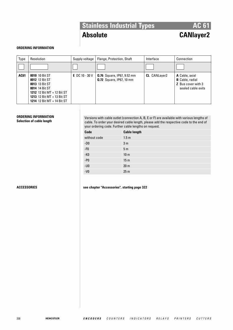
220 E N C O D E R S C O U N T E R S I N D I C A T O R S R E L A Y S P R I N T E R S C U T T E R S
Stainless Industrial Types AC 61Absolute CANlayer2
ORDERING INFORMATION
Type Resolution Supply voltage Flange, Protection, Shaft Interface Connection
AC61 0010 10 Bit ST0012 12 Bit ST0013 13 Bit ST0014 14 Bit ST1212 12 Bit MT + 12 Bit ST1213 12 Bit MT + 13 Bit ST1214 12 Bit MT + 14 Bit ST
E DC 10 - 30 V Q.76 Square, IP67, 9.52 mmQ.72 Square, IP67, 10 mm
CL CANLayer2 A Cable, axialB Cable, radialZ Bus cover with 3
sealed cable exits
ORDERING INFORMATION Selection of cable length
Versions with cable outlet (connection A, B, E or F) are available with various lengths ofcable. To order your desired cable length, please add the respective code to the end ofyour ordering code. Further cable lengths on request.
Code Cable length
without code 1.5 m
-D0 3 m
-F0 5 m
-K0 10 m
-P0 15 m
-U0 20 m
-V0 25 m
ACCESSORIES see chapter "Accessories", starting page 322

221E N C O D E R S C O U N T E R S I N D I C A T O R S R E L A Y S P R I N T E R S C U T T E R S
Stainless Industrial Types AC 61Absolute DeviceNet
Version AC 61 with bus cover
� Compact design� Protection class IP67� High corrosion resistance� Robust design� Resolution up to 26 Bit (14 Bit ST, 12 Bit MT)� Bus cover� Programmable: Resolution, Preset, Direction� Allan-Bradley compatible� Applications: packaging machine for food and beverage, ship equipment (e.g. cranes,
winches, cable laying ships), offshore applications
GENERAL INFORMATION The absolute stainless steel encoders are available in the Versions AC 59 and AC 61. � AC 59: drawn stainless steel housing, only together with cable outlet, no access to con-
trol elements � AC 61: machined housing, possible with cable or bus cover, access to control elements
(DIP switch, Reset switch)
TECHNICAL DATA mechanical
Housing diameter 61.5 mm
Shaft diameter 9.52 mm / 10 mm (Solid shaft)
Flange (Mounting of housing)
Square flange 63.5 mm
Protection class shaft input (EN 60529)
IP67
Protection class housing (EN 60529)
IP67
Shaft load axial / radial 40 N / 60 N
Max. speed max. 6000 rpm (continuous), max. 10 000 rpm (short term)
Torque ≤ 1 Ncm
Moment of inertia approx. 20 gcm²
Vibration resistance (DIN EN 60068-2-6)
100 m/s² (10 ... 500 Hz)
Shock resistance (DIN EN 60068-2-27)
1000 m/s² (6 ms)
Operating temperature -40 °C ... +85 °C
Storage temperature -40 °C ... +85 °C
Material shaft Stainless Steel
Material housing Stainless Steel
Weight approx. 1180 g
Connection Bus cover with 2 sealed cable exits
TECHNICAL DATA electrical
General design as per DIN EN 61010-1, protection class III, contamina-tion level 2, overvoltage class II
Supply voltage DC 10-30 V
Max. current w/o load 220 mA (ST), 250 mA (MT)
EMC Noise emission according to EN 50081-2Immunity to interference according to EN 50082-2
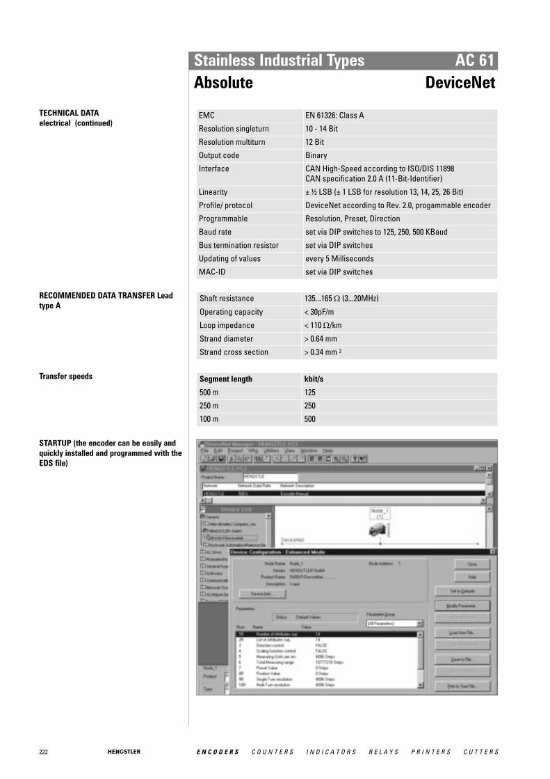
222 E N C O D E R S C O U N T E R S I N D I C A T O R S R E L A Y S P R I N T E R S C U T T E R S
Stainless Industrial Types AC 61Absolute DeviceNet
TECHNICAL DATA electrical (continued)
EMC EN 61326: Class A
Resolution singleturn 10 - 14 Bit
Resolution multiturn 12 Bit
Output code Binary
Interface CAN High-Speed according to ISO/DIS 11898CAN specification 2.0 A (11-Bit-Identifier)
Linearity ± ½ LSB (± 1 LSB for resolution 13, 14, 25, 26 Bit)
Profile/ protocol DeviceNet according to Rev. 2.0, progammable encoder
Programmable Resolution, Preset, Direction
Baud rate set via DIP switches to 125, 250, 500 KBaud
Bus termination resistor set via DIP switches
Updating of values every 5 Milliseconds
MAC-ID set via DIP switches
RECOMMENDED DATA TRANSFER Leadtype A
Shaft resistance 135...165 Ω (3...20MHz)
Operating capacity < 30pF/m
Loop impedance < 110 Ω/km
Strand diameter > 0.64 mm
Strand cross section > 0.34 mm 2
Transfer speeds Segment length kbit/s
500 m 125
250 m 250
100 m 500
STARTUP (the encoder can be easily andquickly installed and programmed with theEDS file)

223E N C O D E R S C O U N T E R S I N D I C A T O R S R E L A Y S P R I N T E R S C U T T E R S
Stainless Industrial Types AC 61Absolute DeviceNet
ELECTRICAL CONNECTIONSBus cover with 2 sealed cable exits
Terminals
No. Signal name
1 UB in (DC 10 - 30V)
2 0 V in
3 CAN-L
4 CAN-H
5 DRAIN
6 DRAIN
7 DRAIN
8 CAN-L
9 0 V out
10 UB out (DC 10 - 30V)
DIMENSIONED DRAWINGS see chapter "Dimensioned drawings AC 59 / AC 61", starting page 232
ORDERING INFORMATION
Type Resolution Supply voltage Flange, Protection, Shaft Interface Connection
AC61 0010 10 Bit ST0012 12 Bit ST0013 13 Bit ST0014 14 Bit ST1212 12 Bit MT + 12 Bit ST1213 12 Bit MT + 13 Bit ST1214 12 Bit MT + 14 Bit ST
E DC 10 - 30 V Q.76 Square, IP67, 9.52 mmQ.72 Square, IP67, 10 mm
VD DeviceNet Z Bus cover with 2sealed cable exits
ACCESSORIES see chapter "Accessories", starting page 322

224 E N C O D E R S C O U N T E R S I N D I C A T O R S R E L A Y S P R I N T E R S C U T T E R S
Stainless Industrial Types AC 61Absolute Interbus
Version AC 61 with bus cover
� Compact design� Protection class IP67� High corrosion resistance� Robust design� Resolution up to 24 Bit (12 Bit ST, 12 Bit MT)� Resolution programmable� Preset (K3)� Direction (K3)� Bus cover� Applications: packaging machine for food and beverage, ship equipment (e.g. cranes,
winches, cable laying ships), offshore applications
GENERAL INFORMATION The absolute stainless steel encoders are available in the Versions AC 59 and AC 61. � AC 59: drawn stainless steel housing, only together with cable outlet, no access to con-
trol elements � AC 61: machined housing, possible with cable or bus cover, access to control elements
(DIP switch, Reset switch)
TECHNICAL DATA mechanical
Housing diameter 61.5 mm
Shaft diameter 9.52 mm / 10 mm (Solid shaft)
Flange (Mounting of housing)
Square flange 63.5 mm
Protection class shaft input (EN 60529)
IP67
Protection class housing (EN 60529)
IP67
Shaft load axial / radial 40 N / 60 N
Max. speed max. 6000 rpm (continuous), max. 10 000 rpm (short term)
Torque ≤ 1 Ncm
Moment of inertia approx. 20 gcm²
Vibration resistance (DIN EN 60068-2-6)
100 m/s² (10 ... 500 Hz)
Shock resistance (DIN EN 60068-2-27)
1000 m/s² (6 ms)
Operating temperature -40 °C ... +70 °C
Storage temperature -40 °C ... +85 °C
Material shaft Stainless Steel
Material housing Stainless Steel
Weight approx. 1180 g
Connection Bus cover with 3 sealed cable exits
TECHNICAL DATA electrical
General design as per DIN EN 61010-1, protection class III, contamina-tion level 2, overvoltage class II
Supply voltage DC 10-30 V
Max. current w/o load 220 mA (ST, recommended external fuse: T 0.25 A), 250 mA (MT, recommended external fuse: T 0.25 A)

225E N C O D E R S C O U N T E R S I N D I C A T O R S R E L A Y S P R I N T E R S C U T T E R S
Stainless Industrial Types AC 61Absolute Interbus
TECHNICAL DATA electrical (continued)
EMC Noise emission according to EN 50081-2Immunity to interference according to EN 50082-2
Resolution singleturn 10 - 12 Bit
Resolution multiturn 12 Bit
Output code 32 Bit binary
Linearity ± ½ LSB
Profile/ protocol ENCOM-Profil K3 = ID-Code 37, K2 = ID-Code 36
Programmable Resolution, Preset, Offset, Direction
Output current 1 max. 4.5 A for bus cover with 2x M23 (recommendedexternal fuse: T 4.5 A)max. 2 A for all other connections (recommended exter-nal fuse: T 2 A)
Baud rate 500 KBaud
Updating of values every 600 μs1 Current with looped through voltage supply
DATA FORMAT Interbus K2/K3 Differential signals (RS485) ENCOM profile K3, K2, 32 Bit, binary process data
Data format Sμpi-address 0 1 2 3
(as per Phoenix) Byte-No. 3 2 1 0
ID-Code K2 36H (= 54 decimal)
ID-Code K3 37H (= 55 decimal)
PROGRAMMABLE FUNKTIONS for Interbus K3
Function (Programming directly via the bus throughtransfer of configuration parame-ters)
Preset values (manufacturer´s standard settings)
Customer-specific parameters
Code sequence for clockwise (cw) rotation
ascending
Offset (KP-No. 05) 0
Preset value (KP-No. 04) 0
Scaling faktor (KP-No. 08) 1 1
1 maximum resolution
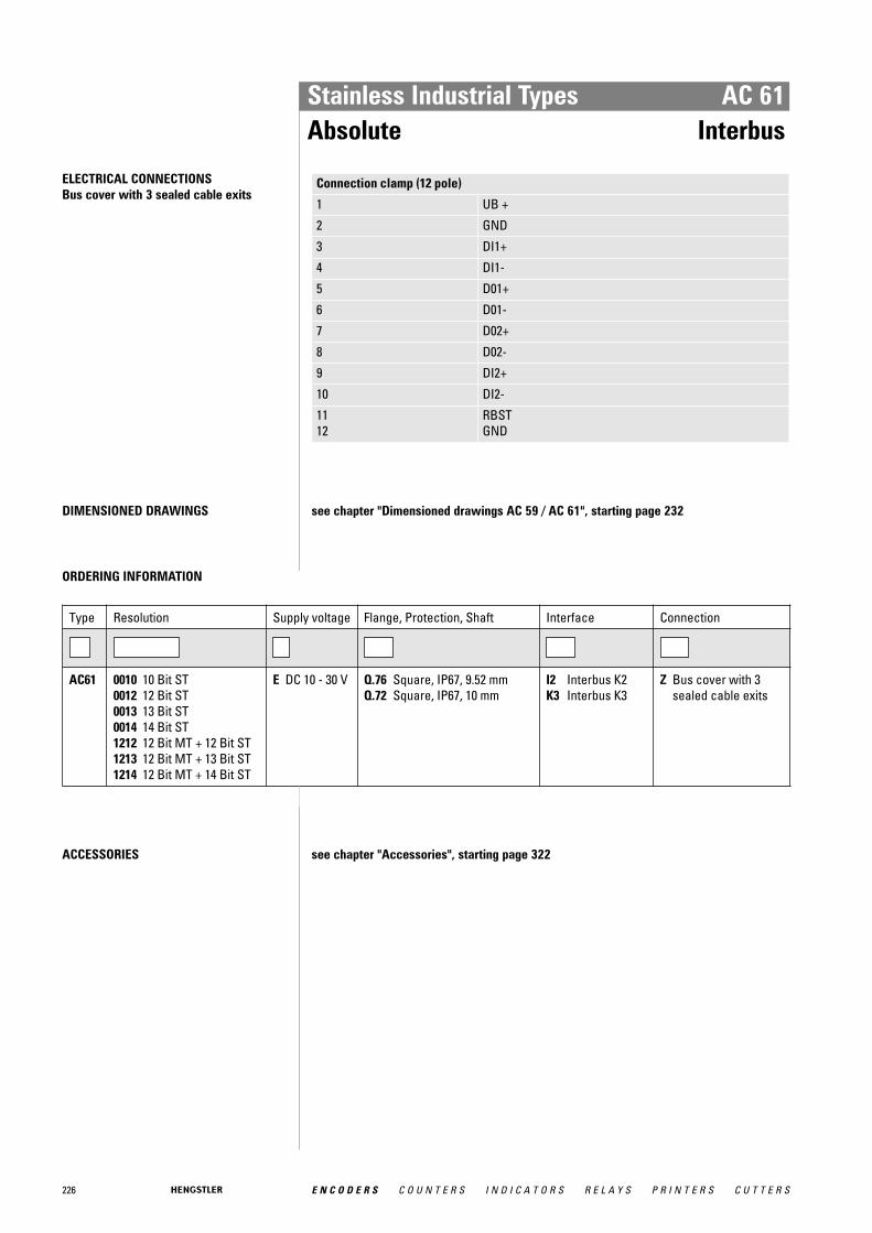
226 E N C O D E R S C O U N T E R S I N D I C A T O R S R E L A Y S P R I N T E R S C U T T E R S
Stainless Industrial Types AC 61Absolute Interbus
ELECTRICAL CONNECTIONSBus cover with 3 sealed cable exits
Connection clamp (12 pole)
1 UB +
2 GND
3 DI1+
4 DI1-
5 D01+
6 D01-
7 D02+
8 D02-
9 DI2+
10 DI2-
11 12
RBST GND
DIMENSIONED DRAWINGS see chapter "Dimensioned drawings AC 59 / AC 61", starting page 232
ORDERING INFORMATION
Type Resolution Supply voltage Flange, Protection, Shaft Interface Connection
AC61 0010 10 Bit ST0012 12 Bit ST0013 13 Bit ST0014 14 Bit ST1212 12 Bit MT + 12 Bit ST1213 12 Bit MT + 13 Bit ST1214 12 Bit MT + 14 Bit ST
E DC 10 - 30 V Q.76 Square, IP67, 9.52 mmQ.72 Square, IP67, 10 mm
I2 Interbus K2K3 Interbus K3
Z Bus cover with 3sealed cable exits
ACCESSORIES see chapter "Accessories", starting page 322
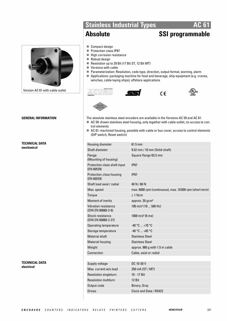
227E N C O D E R S C O U N T E R S I N D I C A T O R S R E L A Y S P R I N T E R S C U T T E R S
Stainless Industrial Types AC 61Absolute SSI programmable
Version AC 61 with cable outlet
� Compact design� Protection class IP67� High corrosion resistance� Robust design� Resolution up to 29 Bit (17 Bit ST, 12 Bit MT)� Versions with cable� Parameterization: Resolution, code type, direction, output format, warning, alarm� Applications: packaging machine for food and beverage, ship equipment (e.g. cranes,
winches, cable laying ships), offshore applications
GENERAL INFORMATION The absolute stainless steel encoders are available in the Versions AC 59 and AC 61. � AC 59: drawn stainless steel housing, only together with cable outlet, no access to con-
trol elements � AC 61: machined housing, possible with cable or bus cover, access to control elements
(DIP switch, Reset switch)
TECHNICAL DATA mechanical
Housing diameter 61.5 mm
Shaft diameter 9.52 mm / 10 mm (Solid shaft)
Flange (Mounting of housing)
Square flange 63.5 mm
Protection class shaft input (EN 60529)
IP67
Protection class housing (EN 60529)
IP67
Shaft load axial / radial 40 N / 60 N
Max. speed max. 6000 rpm (continuous), max. 10 000 rpm (short term)
Torque ≤ 1 Ncm
Moment of inertia approx. 20 gcm²
Vibration resistance (DIN EN 60068-2-6)
100 m/s² (10 ... 500 Hz)
Shock resistance (DIN EN 60068-2-27)
1000 m/s² (6 ms)
Operating temperature -40 °C ... +70 °C
Storage temperature -40 °C ... +85 °C
Material shaft Stainless Steel
Material housing Stainless Steel
Weight approx. 980 g with 1.5 m cable
Connection Cable, axial or radial
TECHNICAL DATA electrical
Supply voltage DC 10-30 V
Max. current w/o load 250 mA (ST / MT)
Resolution singleturn 10 - 17 Bit
Resolution multiturn 12 Bit
Output code Binary, Gray
Drives Clock and Data / RS422
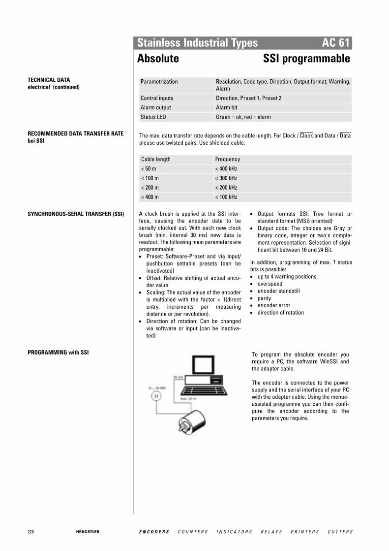
228 E N C O D E R S C O U N T E R S I N D I C A T O R S R E L A Y S P R I N T E R S C U T T E R S
Stainless Industrial Types AC 61Absolute SSI programmable
TECHNICAL DATA electrical (continued)
Parametrization Resolution, Code type, Direction, Output format, Warning,Alarm
Control inputs Direction, Preset 1, Preset 2
Alarm output Alarm bit
Status LED Green = ok, red = alarm
RECOMMENDED DATA TRANSFER RATEbei SSI
The max. data transfer rate depends on the cable length. For Clock / Clock and Data / Dataplease use twisted pairs. Use shielded cable.
Cable length Frequency
< 50 m < 400 kHz
< 100 m < 300 kHz
< 200 m < 200 kHz
< 400 m < 100 kHz
SYNCHRONOUS-SERAL TRANSFER (SSI) A clock brush is applied at the SSI inter-face, causing the encoder data to be serially clocked out. With each new clockbrush (min. interval 30 ms) new data is readout. The following main parameters areprogrammable: • Preset: Software-Preset and via input/
pushbutton settable presets (can beinactivated)
• Offset: Relative shifting of actual enco-der value.
• Scaling: The actual value of the encoderis multiplied with the factor < 1(directentry, increments per measuringdistance or per revolution).
• Direction of rotation: Can be changedvia software or input (can be inactiva-ted)
• Output formats SSI: Tree format or standard format (MSB oriented)
• Output code: The choices are Gray orbinary code, integer or two's comple-ment representation. Selection of signi-ficant bit between 16 and 24 Bit.
In addition, programming of max. 7 statusbits is possible: • up to 4 warning positions • overspeed • encoder standstill • parity • encoder error • direction of rotation
PROGRAMMING with SSI To program the absolute encoder yourequire a PC, the software WinSSI andthe adapter cable.
The encoder is connected to the powersupply and the serial interface of your PCwith the adapter cable. Using the menue-assisted programme you can then confi-gure the encoder according to theparameters you require.
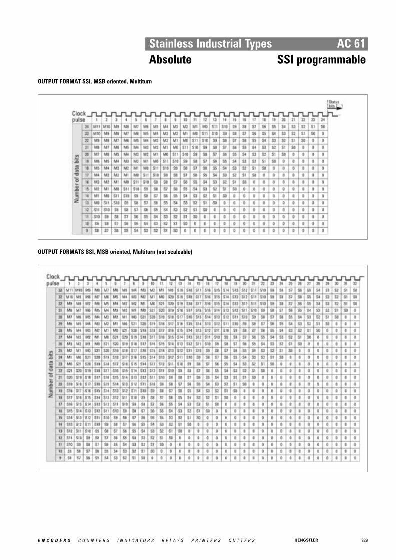
229E N C O D E R S C O U N T E R S I N D I C A T O R S R E L A Y S P R I N T E R S C U T T E R S
Stainless Industrial Types AC 61Absolute SSI programmable
OUTPUT FORMAT SSI, MSB oriented, Multiturn
OUTPUT FORMATS SSI, MSB oriented, Multiturn (not scaleable)

230 E N C O D E R S C O U N T E R S I N D I C A T O R S R E L A Y S P R I N T E R S C U T T E R S
Stainless Industrial Types AC 61Absolute SSI programmable
OUTPUT FORMAT SSI, tree format
ELECTRICAL CONNECTIONS12 pole / cable
Cable Colour Signal
green Clock
yellow Clock
pink Data
grey Data
brown RS 232 TxD
white RS 232 RxD
black 0 V signal output
blue Direction
red Preset 1
violet Preset 2
white 1 DC 10 - 30 V
brown 1 0 V (supply voltage) 1 bigger cross section 0.5 mm 2
DIMENSIONED DRAWINGS see chapter "Dimensioned drawings AC 59 / AC 61", starting page 232

231E N C O D E R S C O U N T E R S I N D I C A T O R S R E L A Y S P R I N T E R S C U T T E R S
Stainless Industrial Types AC 61Absolute SSI programmable
ORDERING INFORMATION
Type Resolution Supply voltage Flange, Protection, Shaft Interface Connection
AC61 0010 10 Bit ST0012 12 Bit ST0013 13 Bit ST0014 14 Bit ST1212 12 Bit MT + 12 Bit ST1213 12 Bit MT + 13 Bit ST1214 12 Bit MT + 14 Bit ST1217 12 Bit MT + 17 Bit SThigher resolution on request
E DC 10 - 30 V Q.76 Square, IP67, 9.52 mmQ.72 Square, IP67, 10 mm
SP SSI pro-grammable
A Cable, axialB Cable, radial
ORDERING INFORMATION Selection of cable length
Versions with cable outlet (connection A, B, E or F) are available with various lengths ofcable. To order your desired cable length, please add the respective code to the end ofyour ordering code. Further cable lengths on request.
Code Cable length
without code 1.5 m
-D0 3 m
-F0 5 m
-K0 10 m
-P0 15 m
-U0 20 m
-V0 25 m
ACCESSORIES see chapter "Accessories", starting page 322

232 E N C O D E R S C O U N T E R S I N D I C A T O R S R E L A Y S P R I N T E R S C U T T E R S
Stainless Industrial Types AC 59 / AC 61Absolute Dimensioned Drawings
DIMENSIONED DRAWINGS
AC 59 Connection cable "A"/ "B"Dimensions in mm
<1> Connection cable "A"<2> Connection cable "B"Cable bending radius R for flexible installation ≥ 15 x cable diameter
Cable bending radius R for fixed installation ≥ 7.5 x cable diameterCable Ø d BiSS/SSI/SSI-P: 7,1 +1,2
Cable Ø d ST-P: 7,8 +0,9
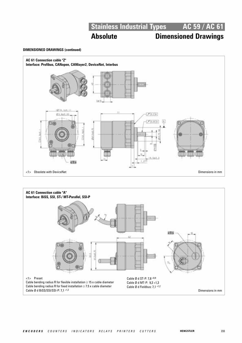
233E N C O D E R S C O U N T E R S I N D I C A T O R S R E L A Y S P R I N T E R S C U T T E R S
Stainless Industrial Types AC 59 / AC 61Absolute Dimensioned Drawings
DIMENSIONED DRAWINGS (continued)
AC 61 Connection cable "Z"Interface: Profibus, CANopen, CANlayer2, DeviceNet, Interbus
<1> Obsolete with DeviceNet Dimensions in mm
AC 61 Connection cable "A"Interface: BiSS, SSI, ST-/ MT-Parallel, SSI-P
<1> PresetCable bending radius R for flexible installation ≥ 15 x cable diameterCable bending radius R for fixed installation ≥ 7.5 x cable diameterCable Ø d BiSS/SSI/SSI-P: 7,1 +1,2
Cable Ø d ST-P: 7,8 +0,9
Cable Ø d MT-P: 9,3 +1,3Cable Ø d Fieldbus: 7,1 +1,2
Dimensions in mm

Stainless Industrial Types AC 59 / AC 61Absolute Dimensioned Drawings
DIMENSIONED DRAWINGS (continued)
AC 61 Connection cable "A"Interface: CANopen, CANlayer2
<1> SettingsCable bending radius R for flexible installation ≥ 15 x cable diameterCable bending radius R for fixed installation ≥ 7.5 x cable diameterCable Ø d BiSS/SSI/SSI-P: 7,1 +1,2
Cable Ø d ST-P: 7,8 +0,9
Cable Ø d MT-P: 9,3 +1,3Cable Ø d Fieldbus: 7,1 +1,2
Dimensions in mm
AC 61 Connection cable "B"
<1> Settings CAN/ CANopen<2> Preset BiSS, SSI, SSI-P, MT-ParallelCable bending radius R for flexible installation ≥ 15 x cable diameterCable bending radius R for fixed installation ≥ 7.5 x cable diameterCable Ø d BiSS/SSI/SSI-P: 7,1 +1,2
Cable Ø d ST-P: 7,8 +0,9
Cable Ø d MT-P: 9,3 +1,3Cable Ø d Fieldbus: 7,1 +1,2
Dimensions in mm
E N C O D E R S C O U N T E R S I N D I C A T O R S R E L A Y S P R I N T E R S C U T T E R S234

235E N C O D E R S C O U N T E R S I N D I C A T O R S R E L A Y S P R I N T E R S C U T T E R S
EEx Industrial Types
The absolute encoder line ACURO® and incremental encoder line“RI” are available with explosion proof enclosure “d” under AX70 orAX71 (stainless steel) for absolute encoders and RX70 or RX71 (stain-less steel) for incremental encoders.
They are approved by PTB and documented via “Declaration of Con-formity” to meet the the requirements of safety and health accordingto EN 50014 and EN 50018. Therefore it’s usage is permitted in explo-sive areas, code „Ex ll 2 G/D E Ex d ll C T4/T6 IP65/ IP66 135°C resp.85°C“.
For applications under tough environmental conditions and foodindustry the stainless steel version AX71 and RX71 are available.
Examples of applications for explosion proof encoders:
■ draw works■ other Oil field applications■ petro chemistry■ enamelling production line■ bottling machines■ mixers■ silo works
EEx
Indu
stria
l

236 E N C O D E R S C O U N T E R S I N D I C A T O R S R E L A Y S P R I N T E R S C U T T E R S
EEx Industrial Types RX 70TI / RX 71TIIncremental
RX 70 - Aluminium
RX 71 - Stainless steel
� Explosion proof class II according to EX II 2 G/D EEX d IIC T6/T4� Highest working reliability� Resolution up to 10 000 ppr� Stainless steel version RX71 available� Applications: enamelling production line, surfacing machines, bottling machines,
mixers, silo works
NUMBER OF PULSES 1 / 2 / 3 / 4 / 5 / 10 / 15 / 20 / 25 / 30 / 35 / 40 / 45 / 50 / 60 / 64 / 70 / 72 / 80 / 100 / 125 / 128 / 144/ 150 / 180 / 200 / 230 / 250 / 256 / 300 / 314 / 350 / 360 / 375 / 400 / 460 / 480 / 500 / 512 / 600 /625 / 635 / 720 / 750 / 900 / 1000 / 1024 / 1200 / 1250 / 1500 / 1600 / 1800 / 2000 / 2048 / 2500 /3000 / 3480 / 3600 / 3750 / 3968 / 4000 / 4096 / 4800 / 5000 / 5400 / 6000 / 7200 / 7680 / 8000 /8192 / 9000 / 10000 Other number of pulses on request
EX-CLASSIFICATION The incremental shaft encoder is available in explosion proof design with explosion proofenclosure "d" under RX 70 and RX 71 (stainless steel). The PTB has assured with the Declaration of Conformity that the RX 70 / 71 meets the requi-rements of safety and health according to EN 50014 and EN 50018. Therefore it is approvedin explosive areas, code "Ex ll 2 G/D E Ex d ll C T4/T6 IP65/ IP66 135°C resp. 85°C". For applications under tough environmental conditions and food industry the stainless steelversion RX 71 is available.
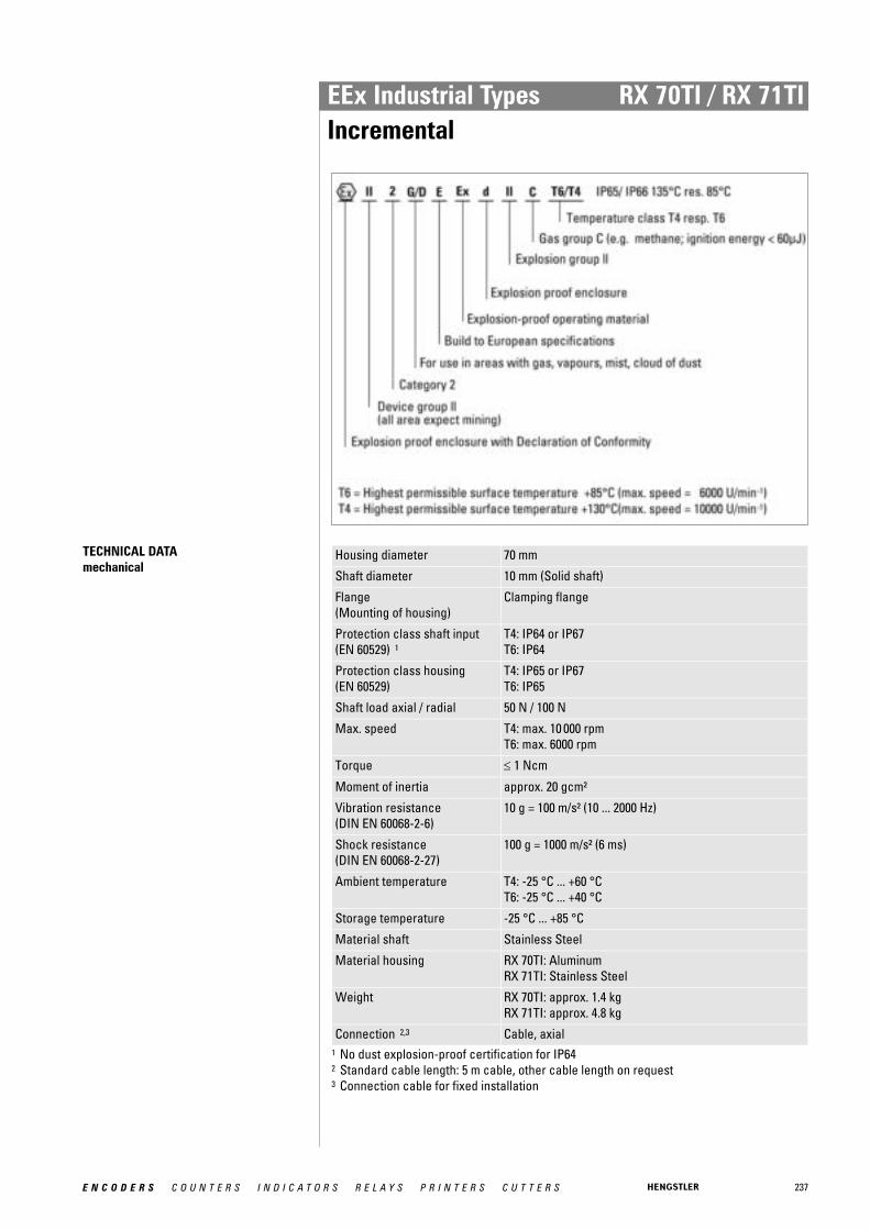
237E N C O D E R S C O U N T E R S I N D I C A T O R S R E L A Y S P R I N T E R S C U T T E R S
EEx Industrial Types RX 70TI / RX 71TIIncremental
TECHNICAL DATA mechanical
Housing diameter 70 mm
Shaft diameter 10 mm (Solid shaft)
Flange (Mounting of housing)
Clamping flange
Protection class shaft input (EN 60529) 1
T4: IP64 or IP67T6: IP64
Protection class housing (EN 60529)
T4: IP65 or IP67T6: IP65
Shaft load axial / radial 50 N / 100 N
Max. speed T4: max. 10 000 rpmT6: max. 6000 rpm
Torque ≤ 1 Ncm
Moment of inertia approx. 20 gcm²
Vibration resistance (DIN EN 60068-2-6)
10 g = 100 m/s² (10 ... 2000 Hz)
Shock resistance (DIN EN 60068-2-27)
100 g = 1000 m/s² (6 ms)
Ambient temperature T4: -25 °C ... +60 °CT6: -25 °C ... +40 °C
Storage temperature -25 °C ... +85 °C
Material shaft Stainless Steel
Material housing RX 70TI: AluminumRX 71TI: Stainless Steel
Weight RX 70TI: approx. 1.4 kgRX 71TI: approx. 4.8 kg
Connection 2,3 Cable, axial1 No dust explosion-proof certification for IP642 Standard cable length: 5 m cable, other cable length on request3 Connection cable for fixed installation
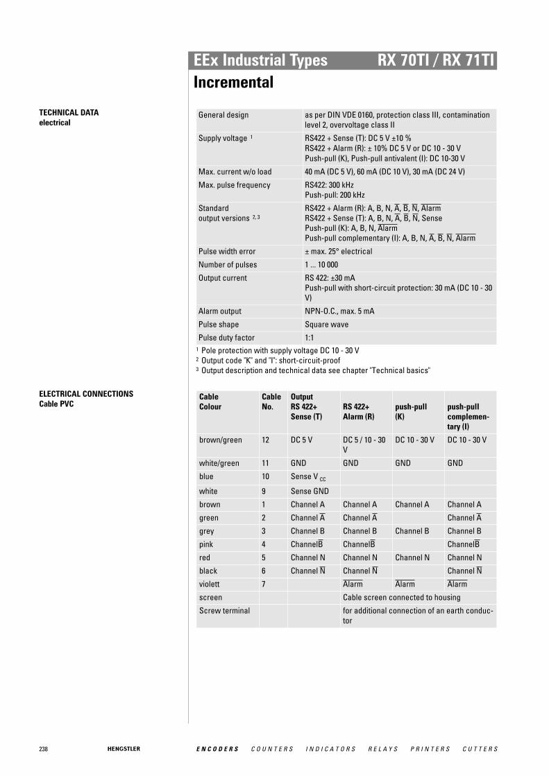
238 E N C O D E R S C O U N T E R S I N D I C A T O R S R E L A Y S P R I N T E R S C U T T E R S
EEx Industrial Types RX 70TI / RX 71TIIncremental
TECHNICAL DATA electrical
General design as per DIN VDE 0160, protection class III, contaminationlevel 2, overvoltage class II
Supply voltage 1 RS422 + Sense (T): DC 5 V ±10 % RS422 + Alarm (R): ± 10% DC 5 V or DC 10 - 30 VPush-pull (K), Push-pull antivalent (I): DC 10-30 V
Max. current w/o load 40 mA (DC 5 V), 60 mA (DC 10 V), 30 mA (DC 24 V)
Max. pulse frequency RS422: 300 kHzPush-pull: 200 kHz
Standard output versions 2, 3
RS422 + Alarm (R): A, B, N, A, B, N, AlarmRS422 + Sense (T): A, B, N, A, B, N, SensePush-pull (K): A, B, N, AlarmPush-pull complementary (I): A, B, N, A, B, N, Alarm
Pulse width error ± max. 25° electrical
Number of pulses 1 ... 10 000
Output current RS 422: ±30 mAPush-pull with short-circuit protection: 30 mA (DC 10 - 30V)
Alarm output NPN-O.C., max. 5 mA
Pulse shape Square wave
Pulse duty factor 1:11 Pole protection with supply voltage DC 10 - 30 V2 Output code "K" and "I": short-circuit-proof3 Output description and technical data see chapter "Technical basics"
ELECTRICAL CONNECTIONSCable PVC
Cable Colour
Cable No.
Output RS 422+ Sense (T)
RS 422+ Alarm (R)
push-pull (K)
push-pull complemen-tary (I)
brown/green 12 DC 5 V DC 5 / 10 - 30V
DC 10 - 30 V DC 10 - 30 V
white/green 11 GND GND GND GND
blue 10 Sense V CC
white 9 Sense GND
brown 1 Channel A Channel A Channel A Channel A
green 2 Channel A Channel A Channel A
grey 3 Channel B Channel B Channel B Channel B
pink 4 ChannelB ChannelB ChannelB
red 5 Channel N Channel N Channel N Channel N
black 6 Channel N Channel N Channel N
violett 7 Alarm Alarm Alarm
screen Cable screen connected to housing
Screw terminal for additional connection of an earth conduc-tor

239E N C O D E R S C O U N T E R S I N D I C A T O R S R E L A Y S P R I N T E R S C U T T E R S
EEx Industrial Types RX 70TI / RX 71TIIncremental
DIMENSIONED DRAWINGS
IP64
<1> mounting thread M6x12Cable bending radius R for flexible installation ≥ 100 mm
Cable bending radius R for fixed installation ≥ 40 mmDimensions in mm
IP67
<1> mounting thread M6x12Cable bending radius R for flexible installation ≥ 150 mm
Cable bending radius R for fixed installation ≥ 40 mmDimensions in mm

240 E N C O D E R S C O U N T E R S I N D I C A T O R S R E L A Y S P R I N T E R S C U T T E R S
EEx Industrial Types RX 70TI / RX 71TIIncremental
ORDERING INFORMATION
Type Model Number ofpulses
Supply voltage 1,
2Flange, Protection, Shaft 3 Output Connection
RX70RX71
Stain-lessSteel
TI Incre-mental
1 ... 10000 A DC 5 VE DC 10 - 30 V
K.42 Clamping, IP64, 10 mmK.72 Clamping, IP67, 10 mm
R RS422 +AlarmT RS422 +SenseK Push-pullI Push-pull complemen-
tary
E TPE cable,axial
1 DC 5 V: only with output "T", "R" available2 DC 10 - 30 V: only with output "K", "I", "R" available3 No dust explosion-proof certification (D) for IP64
ORDERING INFORMATION Selection of cable length
Versions with cable outlet (connection A, B, E or F) are available with various lengths ofcable. To order your desired cable length, please add the respective code to the end ofyour ordering code. Further cable lengths on request.
Code Cable length
-F0 / without code 5 m
-K0 10 m
-P0 15 m
-U0 20 m
-V0 25 m
ACCESSORIES see chapter "Accessories", starting page 322
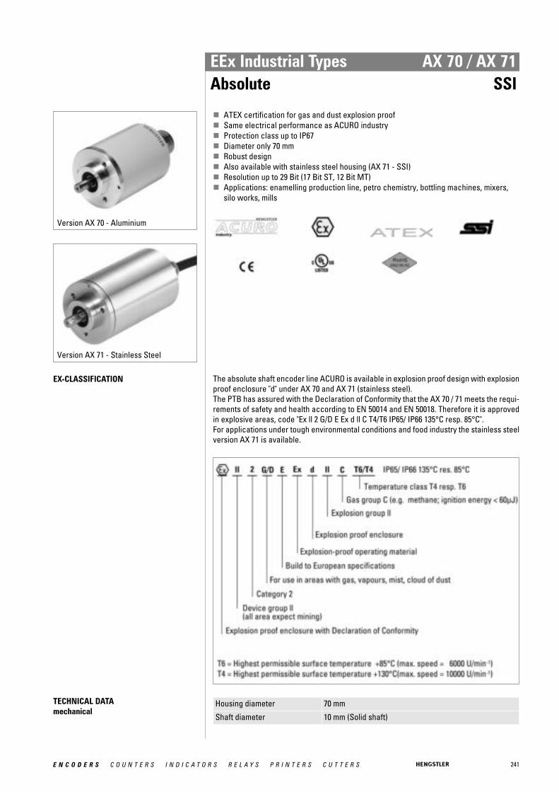
241E N C O D E R S C O U N T E R S I N D I C A T O R S R E L A Y S P R I N T E R S C U T T E R S
EEx Industrial Types AX 70 / AX 71Absolute SSI
Version AX 70 - Aluminium
Version AX 71 - Stainless Steel
� ATEX certification for gas and dust explosion proof� Same electrical performance as ACURO industry� Protection class up to IP67� Diameter only 70 mm� Robust design� Also available with stainless steel housing (AX 71 - SSI)� Resolution up to 29 Bit (17 Bit ST, 12 Bit MT)� Applications: enamelling production line, petro chemistry, bottling machines, mixers,
silo works, mills
EX-CLASSIFICATION The absolute shaft encoder line ACURO is available in explosion proof design with explosionproof enclosure "d" under AX 70 and AX 71 (stainless steel). The PTB has assured with the Declaration of Conformity that the AX 70 / 71 meets the requi-rements of safety and health according to EN 50014 and EN 50018. Therefore it is approvedin explosive areas, code "Ex ll 2 G/D E Ex d ll C T4/T6 IP65/ IP66 135°C resp. 85°C". For applications under tough environmental conditions and food industry the stainless steelversion AX 71 is available.
TECHNICAL DATA mechanical
Housing diameter 70 mm
Shaft diameter 10 mm (Solid shaft)
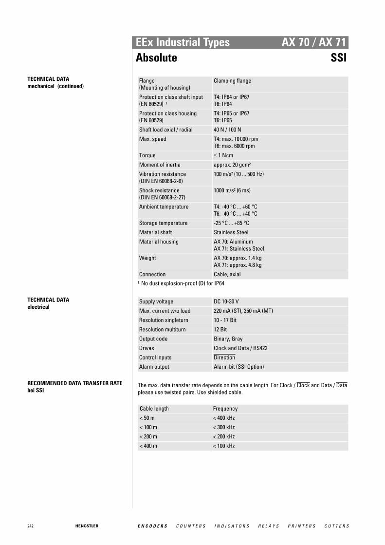
242 E N C O D E R S C O U N T E R S I N D I C A T O R S R E L A Y S P R I N T E R S C U T T E R S
EEx Industrial Types AX 70 / AX 71Absolute SSI
TECHNICAL DATA mechanical (continued)
Flange (Mounting of housing)
Clamping flange
Protection class shaft input (EN 60529) 1
T4: IP64 or IP67T6: IP64
Protection class housing (EN 60529)
T4: IP65 or IP67T6: IP65
Shaft load axial / radial 40 N / 100 N
Max. speed T4: max. 10 000 rpmT6: max. 6000 rpm
Torque ≤ 1 Ncm
Moment of inertia approx. 20 gcm²
Vibration resistance (DIN EN 60068-2-6)
100 m/s² (10 ... 500 Hz)
Shock resistance (DIN EN 60068-2-27)
1000 m/s² (6 ms)
Ambient temperature T4: -40 °C ... +60 °CT6: -40 °C ... +40 °C
Storage temperature -25 °C ... +85 °C
Material shaft Stainless Steel
Material housing AX 70: AluminumAX 71: Stainless Steel
Weight AX 70: approx. 1.4 kgAX 71: approx. 4.8 kg
Connection Cable, axial1 No dust explosion-proof (D) for IP64
TECHNICAL DATA electrical
Supply voltage DC 10-30 V
Max. current w/o load 220 mA (ST), 250 mA (MT)
Resolution singleturn 10 - 17 Bit
Resolution multiturn 12 Bit
Output code Binary, Gray
Drives Clock and Data / RS422
Control inputs Direction
Alarm output Alarm bit (SSI Option)
RECOMMENDED DATA TRANSFER RATEbei SSI
The max. data transfer rate depends on the cable length. For Clock / Clock and Data / Dataplease use twisted pairs. Use shielded cable.
Cable length Frequency
< 50 m < 400 kHz
< 100 m < 300 kHz
< 200 m < 200 kHz
< 400 m < 100 kHz
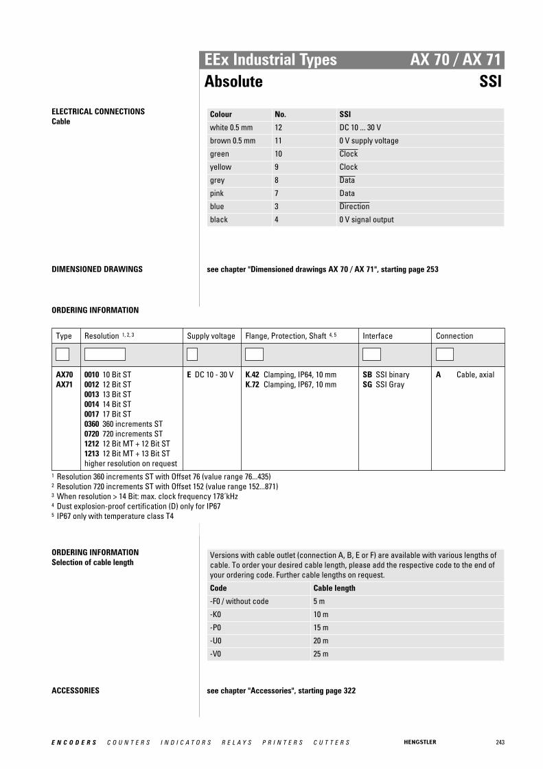
243E N C O D E R S C O U N T E R S I N D I C A T O R S R E L A Y S P R I N T E R S C U T T E R S
EEx Industrial Types AX 70 / AX 71Absolute SSI
ELECTRICAL CONNECTIONSCable
Colour No. SSI
white 0.5 mm 12 DC 10 ... 30 V
brown 0.5 mm 11 0 V supply voltage
green 10 Clock
yellow 9 Clock
grey 8 Data
pink 7 Data
blue 3 Direction
black 4 0 V signal output
DIMENSIONED DRAWINGS see chapter "Dimensioned drawings AX 70 / AX 71", starting page 253
ORDERING INFORMATION
Type Resolution 1, 2, 3 Supply voltage Flange, Protection, Shaft 4, 5 Interface Connection
AX70AX71
0010 10 Bit ST0012 12 Bit ST0013 13 Bit ST0014 14 Bit ST0017 17 Bit ST0360 360 increments ST0720 720 increments ST1212 12 Bit MT + 12 Bit ST1213 12 Bit MT + 13 Bit SThigher resolution on request
E DC 10 - 30 V K.42 Clamping, IP64, 10 mmK.72 Clamping, IP67, 10 mm
SB SSI binarySG SSI Gray
A Cable, axial
1 Resolution 360 increments ST with Offset 76 (value range 76...435)2 Resolution 720 increments ST with Offset 152 (value range 152...871)3 When resolution > 14 Bit: max. clock frequency 178´kHz4 Dust explosion-proof certification (D) only for IP675 IP67 only with temperature class T4
ORDERING INFORMATION Selection of cable length
Versions with cable outlet (connection A, B, E or F) are available with various lengths ofcable. To order your desired cable length, please add the respective code to the end ofyour ordering code. Further cable lengths on request.
Code Cable length
-F0 / without code 5 m
-K0 10 m
-P0 15 m
-U0 20 m
-V0 25 m
ACCESSORIES see chapter "Accessories", starting page 322

244 E N C O D E R S C O U N T E R S I N D I C A T O R S R E L A Y S P R I N T E R S C U T T E R S
EEx Industrial Types AX 70 / AX 71Absolute Profibus
� ATEX certification for gas and dust explosion proof� Same electrical performance as ACURO industry� Protection class up to IP67� Diameter only 70 mm� Robust design� Also available with stainless steel housing (AX 71 - Profibus)� Resolution up to 26 Bit (14 Bit ST, 12 Bit MT)� Applications: enamelling production line, petro chemistry, bottling machines, mixers,
silo works, mills
EX-CLASSIFICATION The absolute shaft encoder line ACURO is available in explosion proof design with explosionproof enclosure "d" under AX 70 and AX 71 (stainless steel). The PTB has assured with the Declaration of Conformity that the AX 70 / 71 meets the requi-rements of safety and health according to EN 50014 and EN 50018. Therefore it is approvedin explosive areas, code "Ex ll 2 G/D E Ex d ll C T4/T6 IP65/ IP66 135°C resp. 85°C". For applications under tough environmental conditions and food industry the stainless steelversion AX 71 is available.
TECHNICAL DATA mechanical
Housing diameter 70 mm
Shaft diameter 10 mm (Solid shaft)
Version AX 70 - Aluminium
Version AX 71 - Stainless Steel

245E N C O D E R S C O U N T E R S I N D I C A T O R S R E L A Y S P R I N T E R S C U T T E R S
EEx Industrial Types AX 70 / AX 71Absolute Profibus
TECHNICAL DATA mechanical (continued)
Flange (Mounting of housing)
Clamping flange
Protection class shaft input (EN 60529) 1
T4: IP64 or IP67T6: IP64
Protection class housing (EN 60529)
T4: IP65 or IP67T6: IP65
Shaft load axial / radial 40 N / 100 N
Max. speed T4: max. 10 000 rpmT6: max. 6000 rpm
Torque ≤ 1 Ncm
Moment of inertia approx. 20 gcm²
Vibration resistance (DIN EN 60068-2-6)
100 m/s² (10 ... 500 Hz)
Shock resistance (DIN EN 60068-2-27)
1000 m/s² (6 ms)
Ambient temperature T4: -40 °C ... +60 °CT6: -40 °C ... +40 °C
Storage temperature -25 °C ... +85 °C
Material shaft Stainless Steel
Material housing AX 70: AluminumAX 71: Stainless Steel
Weight AX 70: approx. 1.4 kgAX 71: approx. 4.8 kg
Connection Cable, axial1 No dust explosion-proof (D) for IP64
TECHNICAL DATA electrical
Supply voltage DC 10-30 V
Max. current w/o load 220 mA (ST), 250 mA (MT)
Resolution singleturn 10 - 14 Bit
Resolution multiturn 12 Bit
Output code Binary
Profile/ protocol Profibus DP with encoder profile class C2 (parameteriza-ble)
Parametrization Resolution, Preset, Direction
Integrated special functions Speed, Acceleration, Operating time
Baud rate is automatically set within a range of 9.6 KBaud through12 MBaud
Device address set via Bus
Bus termination resistor external mounting
246 E N C O D E R S C O U N T E R S I N D I C A T O R S R E L A Y S P R I N T E R S C U T T E R S
EEx Industrial Types AX 70 / AX 71Absolute Profibus
ELECTRICAL CONNECTIONSCable
Color Profibus
yellow B in
green A in
pink B out
grey A out
blue GND1 (M5V 1 )
brown VCC1 (P5V 1 )
white 0.5 mm DC 10 ... 30 V
brown 0.5 mm 0 V
Screen Screen connected to encoder housing 1 used for power supply for an external bus termination resistor
DIMENSIONED DRAWINGS see chapter "Dimensioned drawings AX 70 / AX 71", starting page 253
ORDERING INFORMATION
Type Resolution Supply voltage Flange, Protection, Shaft 1, 2 Interface Connection
AX70AX71
0010 10 Bit ST0012 12 Bit ST0013 13 Bit ST0014 14 Bit ST1212 12 Bit MT + 12
Bit ST1213 12 Bit MT + 13
Bit ST1214 12 Bit MT + 14
Bit ST
E DC 10 - 30 V K.42 Clamping, IP64, 10 mmK.72 Clamping, IP67, 10 mm
DP Profibus A Cable, axial
1 Dust explosion-proof certification (D) only for IP672 IP67 only with temperature class T4
ORDERING INFORMATION Selection of cable length
Versions with cable outlet (connection A, B, E or F) are available with various lengths ofcable. To order your desired cable length, please add the respective code to the end ofyour ordering code. Further cable lengths on request.
Code Cable length
-F0 / without code 5 m
-K0 10 m
-P0 15 m
-U0 20 m
-V0 25 m
ACCESSORIES see chapter "Accessories", starting page 322

247E N C O D E R S C O U N T E R S I N D I C A T O R S R E L A Y S P R I N T E R S C U T T E R S
EEx Industrial Types AX 70 / AX 71Absolute CANopen
� ATEX certification for gas and dust explosion proof� Same electrical performance as ACURO industry� Protection class up to IP67� Diameter only 70 mm� Robust design� Also available with stainless steel housing (AX 71 - CANopen)� Resolution up to 26 Bit (14 Bit ST, 12 Bit MT)� Applications: enamelling production line, petro chemistry, bottling machines, mixers,
silo works, mills
EX-CLASSIFICATION The absolute shaft encoder line ACURO is available in explosion proof design with explosionproof enclosure "d" under AX 70 and AX 71 (stainless steel). The PTB has assured with the Declaration of Conformity that the AX 70 / 71 meets the requi-rements of safety and health according to EN 50014 and EN 50018. Therefore it is approvedin explosive areas, code "Ex ll 2 G/D E Ex d ll C T4/T6 IP65/ IP66 135°C resp. 85°C". For applications under tough environmental conditions and food industry the stainless steelversion AX 71 is available.
TECHNICAL DATA mechanical
Housing diameter 70 mm
Shaft diameter 10 mm (Solid shaft)
Version AX 70 - Aluminium
Version AX 71 - Stainless Steel

248 E N C O D E R S C O U N T E R S I N D I C A T O R S R E L A Y S P R I N T E R S C U T T E R S
EEx Industrial Types AX 70 / AX 71Absolute CANopen
TECHNICAL DATA mechanical (continued)
Flange (Mounting of housing)
Clamping flange
Protection class shaft input (EN 60529) 1
T4: IP64 or IP67T6: IP64
Protection class housing (EN 60529)
T4: IP65 or IP67T6: IP65
Shaft load axial / radial 40 N / 100 N
Max. speed T4: max. 10 000 rpmT6: max. 6000 rpm
Torque ≤ 1 Ncm
Moment of inertia approx. 20 gcm²
Vibration resistance (DIN EN 60068-2-6)
100 m/s² (10 ... 500 Hz)
Shock resistance (DIN EN 60068-2-27)
1000 m/s² (6 ms)
Ambient temperature T4: -40 °C ... +60 °CT6: -40 °C ... +40 °C
Storage temperature -25 °C ... +85 °C
Material shaft Stainless Steel
Material housing AX 70: AluminumAX 71: Stainless Steel
Weight AX 70: approx. 1.4 kgAX 71: approx. 4.8 kg
Connection Cable, axial1 No dust explosion-proof (D) for IP64
TECHNICAL DATA electrical
Supply voltage DC 10-30 V
Max. current w/o load 250 mA (ST / MT)
Resolution singleturn 10 - 14 Bit
Resolution multiturn 12 Bit
Output code Binary
Profile/ protocol CANopen according to DS 301 with profile DSP 406, pro-grammable encoder according class C2
Parametrization Resolution, Preset, Offset, Direction
Integrated special functions Speed, Acceleration, Rotery axis, Limit values, Operatingtime
Bus termination resistor external mounting
ELECTRICAL CONNECTIONSCable
Colour CANopen
yellow CAN in+
green CAN in-
pink CAN out+
grey CAN out-
blue CAN GND in
black CAN GND out
white 0.5 mm UB in
brown 0.5 mm 0 V in
Screen Screen connected with encoder housing

249E N C O D E R S C O U N T E R S I N D I C A T O R S R E L A Y S P R I N T E R S C U T T E R S
EEx Industrial Types AX 70 / AX 71Absolute CANopen
DIMENSIONED DRAWINGS see chapter "Dimensioned drawings AX 70 / AX 71", starting page 253
ORDERING INFORMATION
Type Resolution Supply voltage Flange, Protection, Shaft 1, 2 Interface Connection
AX70AX71
0010 10 Bit ST0012 12 Bit ST0013 13 Bit ST0014 14 Bit ST1212 12 Bit MT + 12 Bit ST1213 12 Bit MT + 13 Bit ST1214 12 Bit MT + 14 Bit ST
E DC 10 - 30 V K.42 Clamping, IP64, 10 mmK.72 Clamping, IP67, 10 mm
OL CANopen A Cable, axial
1 Dust explosion-proof certification (D) only for IP672 IP67 only with temperature class T4
ORDERING INFORMATION Selection of cable length
Versions with cable outlet (connection A, B, E or F) are available with various lengths ofcable. To order your desired cable length, please add the respective code to the end ofyour ordering code. Further cable lengths on request.
Code Cable length
-F0 / without code 5 m
-K0 10 m
-P0 15 m
-U0 20 m
-V0 25 m
ACCESSORIES see chapter "Accessories", starting page 322
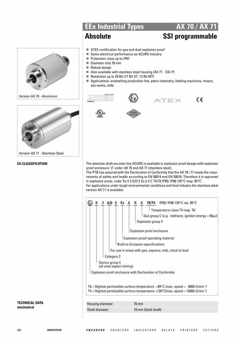
250 E N C O D E R S C O U N T E R S I N D I C A T O R S R E L A Y S P R I N T E R S C U T T E R S
EEx Industrial Types AX 70 / AX 71Absolute SSI programmable
� ATEX certification for gas and dust explosion proof� Same electrical performance as ACURO industry� Protection class up to IP67� Diameter only 70 mm� Robust design� Also available with stainless steel housing (AX 71 - SSI-P)� Resolution up to 29 Bit (17 Bit ST, 12 Bit MT)� Applications: enamelling production line, petro chemistry, bottling machines, mixers,
silo works, mills
EX-CLASSIFICATION The absolute shaft encoder line ACURO is available in explosion proof design with explosionproof enclosure "d" under AX 70 and AX 71 (stainless steel). The PTB has assured with the Declaration of Conformity that the AX 70 / 71 meets the requi-rements of safety and health according to EN 50014 and EN 50018. Therefore it is approvedin explosive areas, code "Ex ll 2 G/D E Ex d ll C T4/T6 IP65/ IP66 135°C resp. 85°C". For applications under tough environmental conditions and food industry the stainless steelversion AX 71 is available.
TECHNICAL DATA mechanical
Housing diameter 70 mm
Shaft diameter 10 mm (Solid shaft)
Version AX 70 - Aluminium
Version AX 71 - Stainless Steel

251E N C O D E R S C O U N T E R S I N D I C A T O R S R E L A Y S P R I N T E R S C U T T E R S
EEx Industrial Types AX 70 / AX 71Absolute SSI programmable
TECHNICAL DATA mechanical (continued)
Flange (Mounting of housing)
Clamping flange
Protection class shaft input (EN 60529) 1
T4: IP64 or IP67T6: IP64
Protection class housing (EN 60529)
T4: IP65 or IP67T6: IP65
Shaft load axial / radial 40 N / 100 N
Max. speed T4: max. 10 000 rpmT6: max. 6000 rpm
Torque ≤ 1 Ncm
Moment of inertia approx. 20 gcm²
Vibration resistance (DIN EN 60068-2-6)
100 m/s² (10 ... 500 Hz)
Shock resistance (DIN EN 60068-2-27)
1000 m/s² (6 ms)
Ambient temperature T4: -40 °C ... +60 °CT6: -40 °C ... +40 °C
Storage temperature -25 °C ... +85 °C
Material shaft Stainless Steel
Material housing AX 70: AluminumAX 71: Stainless Steel
Weight AX 70: approx. 1.4 kgAX 71: approx. 4.8 kg
Connection Cable, axial1 No dust explosion-proof (D) for IP64
TECHNICAL DATA electrical
Supply voltage DC 10-30 V
Max. current w/o load 250 mA (ST / MT)
Resolution singleturn 10 - 17 Bit
Resolution multiturn 12 Bit
Output code Binary, Gray
Drives Clock and Data / RS422
Parametrization Resolution, Code type, Direction, Output format, Warning,Alarm, Preset values
Control inputs Direction, Preset 1, Preset 2
Alarm output Alarm bit1 Programmable with WIN SSI
RECOMMENDED DATA TRANSFER RATEbei SSI
The max. data transfer rate depends on the cable length. For Clock / Clock and Data / Dataplease use twisted pairs. Use shielded cable.
Cable length Frequency
< 50 m < 400 kHz
< 100 m < 300 kHz
< 200 m < 200 kHz
< 400 m < 100 kHz

252 E N C O D E R S C O U N T E R S I N D I C A T O R S R E L A Y S P R I N T E R S C U T T E R S
ACCESSORIES see chapter "Accessories", starting page 322
EEx Industrial Types AX 70 / AX 71Absolute SSI programmable
ELECTRICAL CONNECTIONSCable
Color No. SSI programmable
white 0.14 mm 6 RS232 RxD
brown 0.14 mm 5 RS232 TxD
green 10 Clock
yellow 9 Clock
grey 8 Data
pink 7 Data
blue 3 Direction
black 4 0 V signal output
red 1 Preset 1
violet 2 Preset 2
brown 0.5 mm 11 0 V supply voltage
white 0.5 mm 12 DC 10 ... 30 V
Screen Screen connected to encoder housing
DIMENSIONED DRAWINGS see chapter "Dimensioned drawings AX 70 / AX 71", starting page 253
ORDERING INFORMATION
Type Resolution Supply voltage Flange, Protection, Shaft 1, 2 Interface Connection
AX70AX71
0010 10 Bit ST0012 12 Bit ST0013 13 Bit ST0014 14 Bit ST0017 17 Bit ST1212 12 Bit MT + 12 Bit ST1213 12 Bit MT + 13 Bit ST1214 12 Bit MT + 14 Bit ST1217 12 Bit MT + 17 Bit SThigher resolution on request
E DC 10 - 30 V K.42 Clamping, IP64, 10 mmK.72 Clamping, IP67, 10 mm
SP SSI pro-grammable
A Cable, axial
1 Dust explosion-proof certification (D) only for IP672 IP67 only with temperature class T4
ORDERING INFORMATION Selection of cable length
Versions with cable outlet (connection A, B, E or F) are available with various lengths ofcable. To order your desired cable length, please add the respective code to the end ofyour ordering code. Further cable lengths on request.
Code Cable length
-F0 / without code 5 m
-K0 10 m
-P0 15 m
-U0 20 m
-V0 25 m

253E N C O D E R S C O U N T E R S I N D I C A T O R S R E L A Y S P R I N T E R S C U T T E R S
EEx Industrial Types AX 70 / AX 71Absolute Dimensioned Drawings
DIMENSIONED DRAWINGS
SSI
<1> mounting thread M6x12Cable bending radius R for flexible installation ≥ 150 mm
Cable bending radius R for fixed installation ≥ 40 mmDimensions in mm

254 E N C O D E R S C O U N T E R S I N D I C A T O R S R E L A Y S P R I N T E R S C U T T E R S
EEx Industrial Types AX 70 / AX 71Absolute Dimensioned Drawings
DIMENSIONED DRAWINGS (continued)
SSI-P, Profibus, CANopen
<1> mounting thread M6x12Cable bending radius R for flexible installation ≥ 150 mm
Cable bending radius R for fixed installation ≥ 40 mmDimensions in mm
255E N C O D E R S C O U N T E R S I N D I C A T O R S R E L A Y S P R I N T E R S C U T T E R S
Light Duty Types
Ligh
t du
ty
If you are looking for a compact, but high-resolution incrementalencoder, then our light duty encoder line offers a broad selection toyou.
With up to 3600 pulses per turn Hengstler’s light duty encoder line isone of the most compact and ones in its class.
Despite its small frame size the encoders have two integrated preci-sion ball bearings, which stand for a long life at high speed (up to10.0000 rpm). The electrical features are in no way inferior to themechanical ones: The encoders are equipped with state-of-the-artoptoasic technology, which increases the encoder’s reliability by itshigh immunity to interference. It is also provided with monitoringelectronics which in the event of failure fires an alarm output. If, forexample, over temperature prevails, or the voltage range is fallenbelow the specified minimum, the alarm output will return a signal.
Examples of applications for Light Duty Encoders:
■ laboratory equipment■ crimping machines■ tampon printing machines■ miniature grinding machines■ FHP motors■ labelling machines■ plotters■ graphic machines■ textile machinery

256 E N C O D E R S C O U N T E R S I N D I C A T O R S R E L A Y S P R I N T E R S C U T T E R S
Light Duty Types PC 9 / PC 9SIncremental
� Provides digital control inputs from operators´s panel� Bidirectional squarewave signal outputs� Up to 512 increments� Continuous and reversible rotation� Non-contacting� Operating temperature -40 ... 100 °C
NUMBER OF PULSES 100 ... 512
TECHNICAL DATA mechanical
Housing diameter PC 9: 22 mmPC 9S: 22.86 mm
Shaft diameter 11/8" / 0.25
Shaft load axial / radial 1/8" shaft: 4 N / 27 N1/4" shaft: 4 N / 4 N
Moment of inertia approx. 0.2 gcm²
Operating temperature -40 °C ... +100 °C
Storage temperature -50 °C ... +125 °C
Relative humidity 90 %, non-condensing
Connection PC 9: 10 pole header (Accessory: 30 cm ribbon cable withconnector, ordering code CA0040012)PC 9S: 5 pole header (Accessory: 30 cm ribbon cable withconnector, ordering code CA0050012)
Recommended matingconnector
PC 9: Thomas & Betts, ordering code 622-1030 (onrequest)PC 9S: AMP, ordering code 103675-4 (on request)
TECHNICAL DATA electrical
Supply voltage DC 5 V ±10 % Standby current 50 μA
Code Incremental, optical
Max. pulse frequency 200 kHz
Index pulse width (N) 90° ± 36° electrical
Phasing 90° ± 18° electrical
Symmetry 180° ± 18° electrical
Number of pulses 100 ... 512
Output signals min. 2.5 V high (VOH), max. 0.5 V low (VOL)
Output current PC 9: 3 mA sink/source (25 °C), 2 mA (100 °C)PC 9S: 6 mA sink/source (25 °C), 4 mA (100 °C)
Pulse shape Square wave
Pulse duty factor 1:1
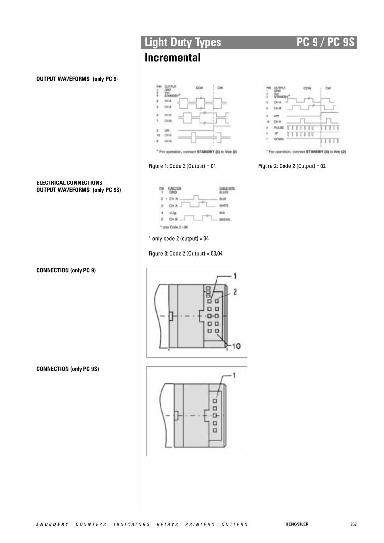
257E N C O D E R S C O U N T E R S I N D I C A T O R S R E L A Y S P R I N T E R S C U T T E R S
Light Duty Types PC 9 / PC 9SIncremental
OUTPUT WAVEFORMS (only PC 9)
Figure 1: Code 2 (Output) = 01 Figure 2: Code 2 (Output) = 02
ELECTRICAL CONNECTIONSOUTPUT WAVEFORMS (only PC 9S)
* only code 2 (output) = 04
Figure 3: Code 2 (Output) = 03/04
CONNECTION (only PC 9)
CONNECTION (only PC 9S)

258 E N C O D E R S C O U N T E R S I N D I C A T O R S R E L A Y S P R I N T E R S C U T T E R S
Light Duty Types PC 9 / PC 9SIncremental
DIMENSIONED DRAWINGS
<1> Mounting Code 3 = M<2> Mounting Code 3 = N
Body length (L) = 0,681'' / 17,3 mm (code 1 = PC9S)Body length (L) = 0,894'' / 22,7 mm (code 2 = PC9 )
ORDERING INFORMATION
Type Number of pulses Code 2: Output Mounting
PC9PC9S
01000144020002560300036005000512
01 see Fig. 1 (PC 9)02 see Fig. 2 (PC 9)03 see Fig. 3 (without index) (PC 9S)04 see Fig. 3 (PC 9S)
M 1/4" shaft, sleeve bearingsN 1/8" shaft, ball bearings
Dimensions in inch [mm]

259E N C O D E R S C O U N T E R S I N D I C A T O R S R E L A Y S P R I N T E R S C U T T E R S
Light Duty Types RI 32Incremental
� Replacement for type Typ RIS and RI 31� The economical encoder for small appliances� High efficiency by means of ball bearing� Small torque� Applications: laboratory equipment, training equipment, crimping machines, tampon
printing machines, miniature grinding machines
NUMBER OF PULSES 5 / 10 / 20 / 25 / 30 / 50 / 60 / 100 / 120 / 128 / 200 / 250 / 256 / 288 / 300 / 360 / 400 / 500 / 512 /600 / 720 / 900 / 1000 / 1024 / 1250 / 1500 Other number of pulses on request
TECHNICAL DATA mechanical
Housing diameter 30 mm
Shaft diameter 5 mm / 6 mm (Solid shaft)
Flange (Mounting of housing)
Pilot flange
Protection class shaft input (EN 60529)
IP40
Protection class housing (EN 60529)
IP50
Shaft load axial / radial 5 N / 10 N
Max. speed max. 6000 rpm
Torque ≤ 0.05 Ncm
Vibration resistance (DIN EN 60068-2-6)
100 m/s² (10 ... 2000 Hz)
Shock resistance (DIN EN 60068-2-27)
1000 m/s² (6 ms)
Operating temperature -10 °C ... +60 °C
Storage temperature -25 °C ... +85 °C
Material shaft Aluminum
Material housing Plastic
Weight approx. 50 g
Connection Cable, axial or radial
TECHNICAL DATA electrical
General design as per DIN VDE 0160, protection class III, contaminationlevel 2, overvoltage class II
Supply voltage 1 Push-pull (D): DC 5 V ±10 % Push-pull (K): ± 10% DC 5 V or DC 10 - 30 V
Max. current w/o load 40 mA (DC 5 V), 60 mA (DC 10 V), 30 mA (DC 24 V)
Max. pulse frequency DC 5 V: 300 kHzDC 10 - 30 V: 200 kHz
Standard output versions 2, 3
Push-pull (K): A, B, N, AlarmPush-pull 5V, ± 30 mA (D): A, B, N, Alarm
Pulse width error ± max. 25° electrical
Number of pulses 5 ... 1500
Alarm output NPN-O.C., max. 5 mA
Pulse shape Square wave
Pulse duty factor 1:1

260 E N C O D E R S C O U N T E R S I N D I C A T O R S R E L A Y S P R I N T E R S C U T T E R S
Light Duty Types RI 32Incremental
TECHNICAL DATA electrical (continued)
1 With push-pull (K): pole protection2 Output code "K": short-circuit-proof3 Output description and technical data see chapter "Technical basics"
ELECTRICAL CONNECTIONSCable
Description (push-pull) Lead ∅∅ mm 2 Colour
DC 5 V/ 10 - 30 V 0.5 red
Channel A 0.14 white
Channel B 0.14 green
Channel N 0.14 yellow
GND 0.5 black
Alarm 0.14 yellow/black
DIMENSIONED DRAWINGS
<1> mounting thread M3x4Cable bending radius R for flexible installation ≥ 100 mm
Cable bending radius R for fixed installation ≥ 40 mmDimensions in mm
ORDERING INFORMATION
Type Number ofpulses
Supply voltage 1 Flange, Protection, Shaft 2, 3 Output 4, 5 Connection
RI32 5 ... 1500 A DC 5 VE DC 10 - 30 V
R.14 Pilot, IP40, 5 mmR.11 Pilot, IP40, 6 mm
K Push-pullD Push-pull 5V, ± 30 mA
A Cable, axialB Cable, radial
1 DC 10 - 30 V: only with output "K" available2 R.11: flattened, see dimensional drawing3 R.14: not flattened4 Output code "K": ±10 mA at DC 5 V, ±30 mA at DC 10 - 30 V5 Output code "K": short-circuit-proof

261E N C O D E R S C O U N T E R S I N D I C A T O R S R E L A Y S P R I N T E R S C U T T E R S
Light Duty Types RI 32Incremental
ORDERING INFORMATION Selection of cable length
Versions with cable outlet (connection A, B, E or F) are available with various lengths ofcable. To order your desired cable length, please add the respective code to the end ofyour ordering code. Further cable lengths on request.
Code Cable length
without code 1.5 m
-D0 3 m
-F0 5 m
-K0 10 m
-P0 15 m
-U0 20 m
-V0 25 m
ACCESSORIES see chapter "Accessories", starting page 322

262 E N C O D E R S C O U N T E R S I N D I C A T O R S R E L A Y S P R I N T E R S C U T T E R S
Light Duty Types RI 38Incremental
� Replacement for type RI 39� Encoder for universal installation by means of front/back panel mounting� High efficiency by means of ball bearing� Small torque� Applications: FHP motors, laboratory equipment, labelling machines, plotters, length
measuring machines
NUMBER OF PULSES 5 / 10 / 20 / 25 / 28 / 32 / 50 / 60 / 72 / 100 / 128 / 144 / 200 / 250 / 256 / 288 / 300 / 360 / 400 / 500/ 512 / 600 / 720 / 900 / 1000 / 1024 Other number of pulses on request
TECHNICAL DATA mechanical
Housing diameter 39 mm
Shaft diameter 6 mm (Solid shaft)
Flange (Mounting of housing)
Square flange
Protection class shaft input (EN 60529)
IP40
Protection class housing (EN 60529)
IP50
Shaft load axial / radial 5 N / 10 N
Max. speed max. 10 000 rpm
Torque ≤ 0.2 Ncm
Vibration resistance (DIN EN 60068-2-6)
100 m/s² (10 ... 2000 Hz)
Shock resistance (DIN EN 60068-2-27)
1000 m/s² (6 ms)
Operating temperature -10 °C ... +60 °C
Storage temperature -25 °C ... +85 °C
Material housing Glass fiber-reinforced plastic
Weight approx. 60 g
Connection Cable, radial
TECHNICAL DATA electrical
General design as per DIN VDE 0160, protection class III, contaminationlevel 2, overvoltage class II
Supply voltage 1 Push-pull (D): DC 5 V ±10 % Push-pull (K): ± 10% DC 5 V or DC 10 - 30 V
Max. current w/o load 40 mA (DC 5 V), 60 mA (DC 10 V), 30 mA (DC 24 V)
Max. pulse frequency DC 5 V: 300 kHzDC 10 - 30 V: 200 kHz
Standard output versions 2, 3
Push-pull (K): A, B, N, AlarmPush-pull 5V, ± 30 mA (D): A, B, N, Alarm
Pulse width error ± max. 25° electrical
Number of pulses 5 ... 1024
Alarm output NPN-O.C., max. 5 mA
Pulse shape Square wave
Pulse duty factor 1:1

263E N C O D E R S C O U N T E R S I N D I C A T O R S R E L A Y S P R I N T E R S C U T T E R S
Light Duty Types RI 38Incremental
TECHNICAL DATA electrical (continued)
1 With push-pull (K): pole protection2 Output code "K": short-circuit-proof3 Output description and technical data see chapter "Technical basics"
ELECTRICAL CONNECTIONSCable
Description (push-pull) Lead ∅∅ mm2 Colour DC 5 V/ 10 - 30 V 0.5 red
Channel A 0.14 white
Channel B 0.14 green Channel N 0.14 yellow GND 0.5 black Alarm 0.14 yellow/black
DIMENSIONED DRAWINGS
<1> mounting thread M3x6Cable bending radius R for flexible installation ≥ 100 mm
Cable bending radius R for fixed installation ≥ 40 mmDimensions in mm
ORDERING INFORMATION
Type Number ofpulses
Supply voltage 1 Flange, Protection, Shaft Output 2, 3 Connection
RI38 5 ... 1024 A DC 5 VE DC 10 - 30 V
Q.11 Square, IP40, 6 mm K Push-pullD Push-pull 5V, ± 30 mA
B Cable, radial
1 DC 10 - 30 V: only with output "K" available2 Output code "K": ±10 mA at DC 5 V, ±30 mA at DC 10 - 30 V3 Output code "K": short-circuit-proof
264 E N C O D E R S C O U N T E R S I N D I C A T O R S R E L A Y S P R I N T E R S C U T T E R S
Light Duty Types RI 38Incremental
ORDERING INFORMATION Selection of cable length
Versions with cable outlet (connection A, B, E or F) are available with various lengths ofcable. To order your desired cable length, please add the respective code to the end ofyour ordering code. Further cable lengths on request.
Code Cable length
without code 1.5 m
-D0 3 m
-F0 5 m
-K0 10 m
-P0 15 m
-U0 20 m
-V0 25 m
ACCESSORIES see chapter "Accessories", starting page 322
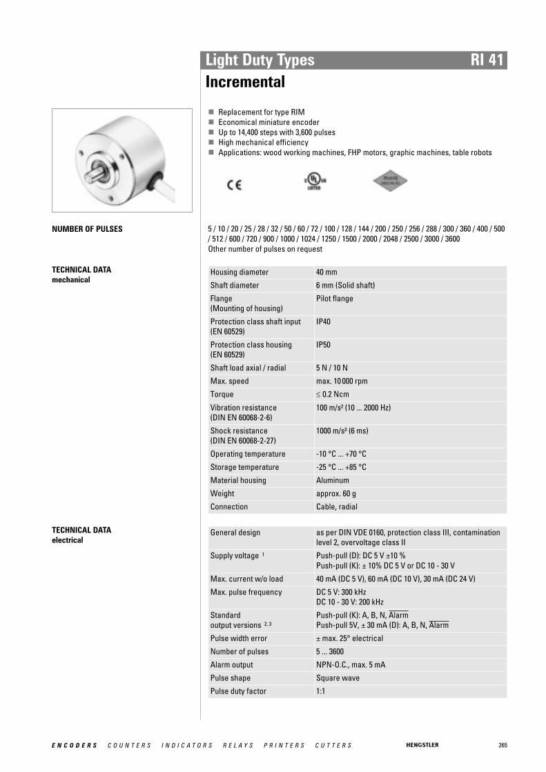
265E N C O D E R S C O U N T E R S I N D I C A T O R S R E L A Y S P R I N T E R S C U T T E R S
Light Duty Types RI 41Incremental
� Replacement for type RIM� Economical miniature encoder� Up to 14,400 steps with 3,600 pulses� High mechanical efficiency� Applications: wood working machines, FHP motors, graphic machines, table robots
NUMBER OF PULSES 5 / 10 / 20 / 25 / 28 / 32 / 50 / 60 / 72 / 100 / 128 / 144 / 200 / 250 / 256 / 288 / 300 / 360 / 400 / 500/ 512 / 600 / 720 / 900 / 1000 / 1024 / 1250 / 1500 / 2000 / 2048 / 2500 / 3000 / 3600 Other number of pulses on request
TECHNICAL DATA mechanical
Housing diameter 40 mm
Shaft diameter 6 mm (Solid shaft)
Flange (Mounting of housing)
Pilot flange
Protection class shaft input (EN 60529)
IP40
Protection class housing (EN 60529)
IP50
Shaft load axial / radial 5 N / 10 N
Max. speed max. 10 000 rpm
Torque ≤ 0.2 Ncm
Vibration resistance (DIN EN 60068-2-6)
100 m/s² (10 ... 2000 Hz)
Shock resistance (DIN EN 60068-2-27)
1000 m/s² (6 ms)
Operating temperature -10 °C ... +70 °C
Storage temperature -25 °C ... +85 °C
Material housing Aluminum
Weight approx. 60 g
Connection Cable, radial
TECHNICAL DATA electrical
General design as per DIN VDE 0160, protection class III, contaminationlevel 2, overvoltage class II
Supply voltage 1 Push-pull (D): DC 5 V ±10 % Push-pull (K): ± 10% DC 5 V or DC 10 - 30 V
Max. current w/o load 40 mA (DC 5 V), 60 mA (DC 10 V), 30 mA (DC 24 V)
Max. pulse frequency DC 5 V: 300 kHzDC 10 - 30 V: 200 kHz
Standard output versions 2, 3
Push-pull (K): A, B, N, AlarmPush-pull 5V, ± 30 mA (D): A, B, N, Alarm
Pulse width error ± max. 25° electrical
Number of pulses 5 ... 3600
Alarm output NPN-O.C., max. 5 mA
Pulse shape Square wave
Pulse duty factor 1:1
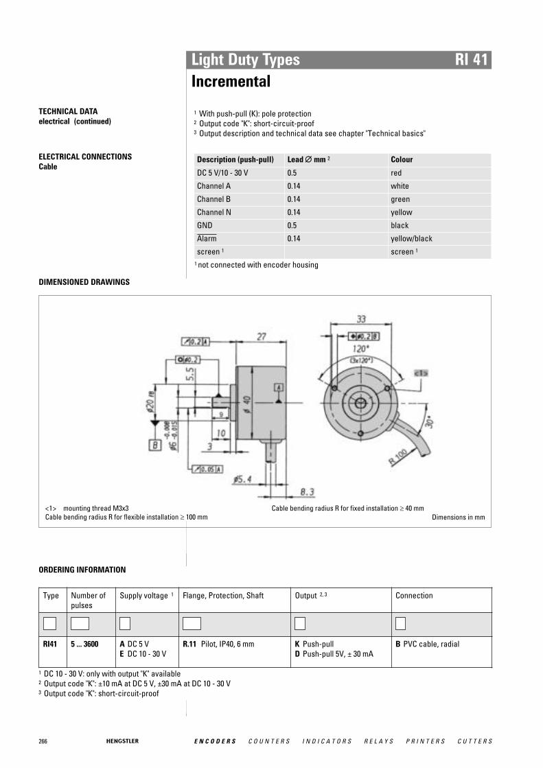
266 E N C O D E R S C O U N T E R S I N D I C A T O R S R E L A Y S P R I N T E R S C U T T E R S
Light Duty Types RI 41Incremental
TECHNICAL DATA electrical (continued)
1 With push-pull (K): pole protection2 Output code "K": short-circuit-proof3 Output description and technical data see chapter "Technical basics"
ELECTRICAL CONNECTIONSCable
Description (push-pull) Lead ∅∅ mm 2 Colour
DC 5 V/10 - 30 V 0.5 red
Channel A 0.14 white
Channel B 0.14 green
Channel N 0.14 yellow
GND 0.5 black
Alarm 0.14 yellow/black
screen 1 screen 1
1 not connected with encoder housing
DIMENSIONED DRAWINGS
<1> mounting thread M3x3Cable bending radius R for flexible installation ≥ 100 mm
Cable bending radius R for fixed installation ≥ 40 mmDimensions in mm
ORDERING INFORMATION
Type Number ofpulses
Supply voltage 1 Flange, Protection, Shaft Output 2, 3 Connection
RI41 5 ... 3600 A DC 5 VE DC 10 - 30 V
R.11 Pilot, IP40, 6 mm K Push-pullD Push-pull 5V, ± 30 mA
B PVC cable, radial
1 DC 10 - 30 V: only with output "K" available2 Output code "K": ±10 mA at DC 5 V, ±30 mA at DC 10 - 30 V3 Output code "K": short-circuit-proof

267E N C O D E R S C O U N T E R S I N D I C A T O R S R E L A Y S P R I N T E R S C U T T E R S
Light Duty Types RI 41Incremental
ORDERING INFORMATION Selection of cable length
Versions with cable outlet (connection A, B, E or F) are available with various lengths ofcable. To order your desired cable length, please add the respective code to the end ofyour ordering code. Further cable lengths on request.
Code Cable length
without code 1.5 m
-D0 3 m
-F0 5 m
-K0 10 m
-P0 15 m
-U0 20 m
-V0 25 m
ACCESSORIES see chapter "Accessories", starting page 322

268 E N C O D E R S C O U N T E R S I N D I C A T O R S R E L A Y S P R I N T E R S C U T T E R S
Light Duty Types RI 42Incremental
� Economical miniature encoder� High protection IP65� Output Push-pull or NPN-O.C.� High mechanical efficiency� Applications: textile machinery
NUMBER OF PULSES 5 / 10 / 20 / 25 / 28 / 32 / 50 / 60 / 72 / 100 / 128 / 144 / 200 / 250 / 256 / 288 / 300 / 360 / 400 / 500/ 512 / 600 / 720 / 900 / 1000 / 1024 Other number of pulses on request
TECHNICAL DATA mechanical
Housing diameter 40 mm
Shaft diameter 6 mm (Solid shaft)
Flange (Mounting of housing)
Pilot flange
Protection class shaft input (EN 60529)
IP64
Protection class housing (EN 60529)
IP65
Shaft load axial / radial 5 N / 10 N
Max. speed max. 10 000 rpm
Torque ≤ 1 Ncm
Vibration resistance (DIN EN 60068-2-6)
100 m/s² (10 ... 2000 Hz)
Shock resistance (DIN EN 60068-2-27)
1000 m/s² (6 ms)
Operating temperature 0 °C ... +60 °C
Storage temperature -25 °C ... +85 °C
Material shaft Aluminum
Material housing Plastic
Weight approx. 75 g
Connection Cable, axial
TECHNICAL DATA electrical
General design as per DIN VDE 0160, protection class III, contaminationlevel 2, overvoltage class II
Supply voltage 1 Push-pull (D): DC 5 V ±10 % Push-pull (K): ± 10% DC 5 V or DC 10 - 30 VPush-pull antivalent (I): DC 10-30 VOpen Collector NPN (S): DC 10-24 V
Max. current w/o load 40 mA (DC 5 V), 30 mA (DC 24 V, with push-pull K, I), 40mA (DC 24 V, NPN-O.C.)
Max. pulse frequency DC 5 V: 300 kHzDC 10 - 30 V: 200 kHzDC 10 - 24 V: 50 kHz
Standard output versions 2, 3, 4
Push-pull (K): A, B, N, AlarmPush-pull 5V, ± 30 mA (D): A, B, N, AlarmPush-pull complementary (I): A, B, N, A, B, N, AlarmNPN-O.C. (S): A, B, N

269E N C O D E R S C O U N T E R S I N D I C A T O R S R E L A Y S P R I N T E R S C U T T E R S
Light Duty Types RI 42Incremental
TECHNICAL DATA electrical (continued)
Pulse width error ± max. 25° electrical
Number of pulses 5 ... 1024
Alarm output NPN-O.C., max. 5 mA
Pulse shape Square wave
Pulse duty factor 1:11 With push-pull (K): pole protection2 Output code "K": short-circuit-proof3 NPN-O.C. with internal pull-up resistor = 10 KΩ , max. pulse frequency = 50 KHz, max.
output lead = ± 30 mA, tolerance ≤ ± 30° electrical, delay time ≤ 4μs4 Output description and technical data see chapter "Technical basics"
ELECTRICAL CONNECTIONSCable
Colour (PVC) Output circuit
push-pull (K, D), Open Collector (S)
push-pull complementary (I)
white Channel A Channel A
white/brown Channel A
green Channel B Channel B
green/brown Channel B
yellow Channel N Channel N
yellow/brown Channel N
yellow/black Alarm Alarm
yellow/red Sense V CC
red DC 5/ 10 - 30/ 10 - 24 V DC 10 - 30 V
black GND GND
DIMENSIONED DRAWINGS
<1> mounting thread M3x5Cable bending radius R for flexible installation ≥ 100 mm
Cable bending radius R for fixed installation ≥ 40 mmDimensions in mm
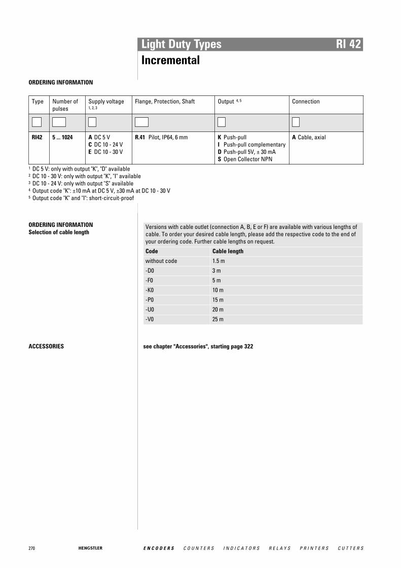
Light Duty Types RI 42Incremental
ORDERING INFORMATION
Type Number ofpulses
Supply voltage1, 2, 3
Flange, Protection, Shaft Output 4, 5 Connection
RI42 5 ... 1024 A DC 5 VC DC 10 - 24 VE DC 10 - 30 V
R.41 Pilot, IP64, 6 mm K Push-pullI Push-pull complementaryD Push-pull 5V, ± 30 mAS Open Collector NPN
A Cable, axial
1 DC 5 V: only with output "K", "D" available2 DC 10 - 30 V: only with output "K", "I" available3 DC 10 - 24 V: only with output "S" available4 Output code "K": ±10 mA at DC 5 V, ±30 mA at DC 10 - 30 V5 Output code "K" and "I": short-circuit-proof
ORDERING INFORMATION Selection of cable length
Versions with cable outlet (connection A, B, E or F) are available with various lengths ofcable. To order your desired cable length, please add the respective code to the end ofyour ordering code. Further cable lengths on request.
Code Cable length
without code 1.5 m
-D0 3 m
-F0 5 m
-K0 10 m
-P0 15 m
-U0 20 m
-V0 25 m
ACCESSORIES see chapter "Accessories", starting page 322
E N C O D E R S C O U N T E R S I N D I C A T O R S R E L A Y S P R I N T E R S C U T T E R S270
271E N C O D E R S C O U N T E R S I N D I C A T O R S R E L A Y S P R I N T E R S C U T T E R S
Motor Feedback
Hengstler offers Motor Feedback systems in all performance classesand with the most commonly used interfaces
From modular miniature incremental encoders for DC and StepperMotors in 22 mm diameter up to the absolute AC110 with 50mm hollow shaft Hengstler provides a complete range of MotorFeedback systems.
For asynchronous motors and elevators the offering comprisesincremental and absolute hollow shaft encoders in singleturn andmultiturn versions. Trend-setting is the Incremental OptoAsic withdiagnosis system and integrated interpolation electronic which is forthe first time used in RI80-E. This enables resolutions of up to 200 000pulses for good synchronism of electric machines running at lowrevs.
For AC Servo Motors there is an extensive range of feedback products available: Brushless resolvers size 10, 15 and 21 uniquelyrobust and low priced, incremental comcoders for direct block commutation of BLDC motors in low cost modular version or withintegrated bearings and resolutions up to 10 000 pulses per revolution.
Your application requires highest precision and dynamics? Than youare on the right track with the Sine-wave encoder S21 and the absolute Acuro-Drive encoder. Latest OptoAsic technology and atrue geared multiturn provides obvious advantages regarding performance and reliability. Hengstler offers the Acuro-Drives serieswith the open, highspeed, digital interface BiSS. With the opensource BiSS interface the proprietary lock-in situation with absolutemotorfeedback systems is broken up with the benefit of an increasing range of suppliers.
One Size fits all:No matter whether your servo application requires resolvers, incremental comcoders or absolute Multiturn encoders - the com-plete range in size 15 with resolver compatible mounting is availablefrom Hengstler. The benefit of this is, that the B-side of the motor canbe resolver style and doesn't need to be customized, depending on thefeedback. The Feedback type can be selected according to customer demands or required resolution and technology. This helpsreducing variation of parts and stock and enables improved deliverytimes.
Mot
orfe
edba
cksy
stem
s
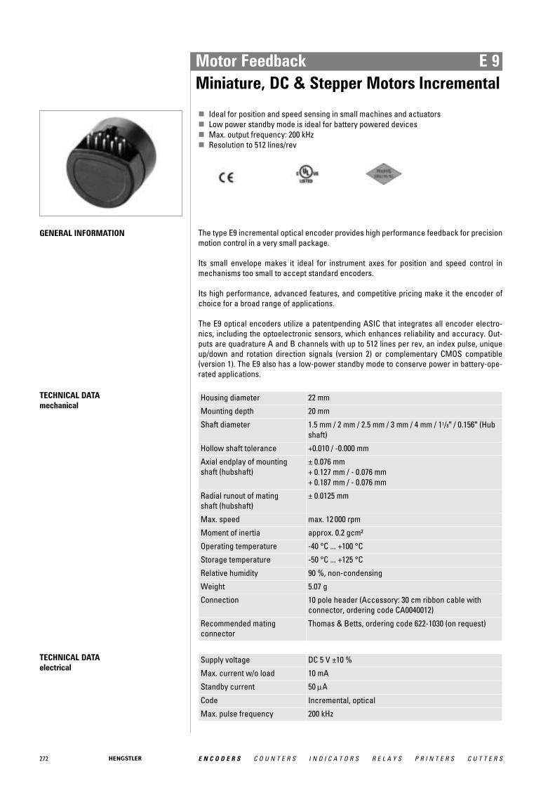
272 E N C O D E R S C O U N T E R S I N D I C A T O R S R E L A Y S P R I N T E R S C U T T E R S
Motor Feedback E 9Miniature, DC & Stepper Motors Incremental
� Ideal for position and speed sensing in small machines and actuators� Low power standby mode is ideal for battery powered devices� Max. output frequency: 200 kHz� Resolution to 512 lines/rev
GENERAL INFORMATION The type E9 incremental optical encoder provides high performance feedback for precisionmotion control in a very small package.
Its small envelope makes it ideal for instrument axes for position and speed control inmechanisms too small to accept standard encoders.
Its high performance, advanced features, and competitive pricing make it the encoder ofchoice for a broad range of applications.
The E9 optical encoders utilize a patentpending ASIC that integrates all encoder electro-nics, including the optoelectronic sensors, which enhances reliability and accuracy. Out-puts are quadrature A and B channels with up to 512 lines per rev, an index pulse, uniqueup/down and rotation direction signals (version 2) or complementary CMOS compatible(version 1). The E9 also has a low-power standby mode to conserve power in battery-ope-rated applications.
TECHNICAL DATA mechanical
Housing diameter 22 mm
Mounting depth 20 mm
Shaft diameter 1.5 mm / 2 mm / 2.5 mm / 3 mm / 4 mm / 11/8" / 0.156" (Hubshaft)
Hollow shaft tolerance +0.010 / -0.000 mm
Axial endplay of mounting shaft (hubshaft)
± 0.076 mm+ 0.127 mm / - 0.076 mm+ 0.187 mm / - 0.076 mm
Radial runout of mating shaft (hubshaft)
± 0.0125 mm
Max. speed max. 12 000 rpm
Moment of inertia approx. 0.2 gcm²
Operating temperature -40 °C ... +100 °C
Storage temperature -50 °C ... +125 °C
Relative humidity 90 %, non-condensing
Weight 5.07 g
Connection 10 pole header (Accessory: 30 cm ribbon cable withconnector, ordering code CA0040012)
Recommended matingconnector
Thomas & Betts, ordering code 622-1030 (on request)
TECHNICAL DATA electrical
Supply voltage DC 5 V ±10 %
Max. current w/o load 10 mA
Standby current 50 μA
Code Incremental, optical
Max. pulse frequency 200 kHz

273E N C O D E R S C O U N T E R S I N D I C A T O R S R E L A Y S P R I N T E R S C U T T E R S
Motor Feedback E 9Miniature, DC & Stepper Motors Incremental
TECHNICAL DATA electrical (continued)
Index pulse width (N) 90° ± 36° electrical
Phasing 90° ± 18° electrical
Symmetry 180° ± 18° electrical
Number of pulses 100 ... 512
Output signals min. 2.5 V high (VOH), max. 0.5 V low (VOL)
Output current 3 mA sink/source (25°C), 2 mA (100°C)
Pulse shape Square wave
OUTPUT WAVEFORMS AND CONNEC-TIONS (Direction viewing encoder cover)
Figure 1 Figure 2 Figure 3
Code 00 for ordering information Code 01 for ordering information Code 02 for ordering information
DIMENSIONED DRAWINGS
<1> Thomas Betts #622-1030 Dimensions in inch [mm]
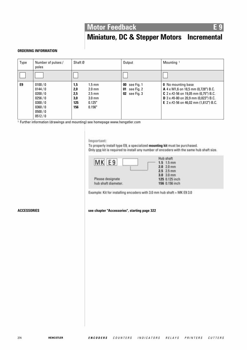
274 E N C O D E R S C O U N T E R S I N D I C A T O R S R E L A Y S P R I N T E R S C U T T E R S
Motor Feedback E 9Miniature, DC & Stepper Motors Incremental
ORDERING INFORMATION
Type Number of pulses / poles
Shaft Ø Output Mounting 1
E9 0100 / 00144 / 00200 / 00256 / 00300 / 00360 / 00500 / 00512 / 0
1,5 1.5 mm2,0 2.0 mm2,5 2.5 mm3,0 3.0 mm125 0.125"156 0.156"
00 see Fig. 101 see Fig. 202 see Fig. 3
0 No mounting baseA 4 x M1,6 on 18,5 mm (0,728") B.C.C 2 x #2-56 on 19,05 mm (0,75") B.C.D 3 x #0-80 on 20,9 mm (0,823") B.C.E 2 x #2-56 on 46,02 mm (1,812") B.C.
1 Further information (drawings and mounting) see homepage www.hengstler.com
ACCESSORIES see chapter "Accessories", starting page 322
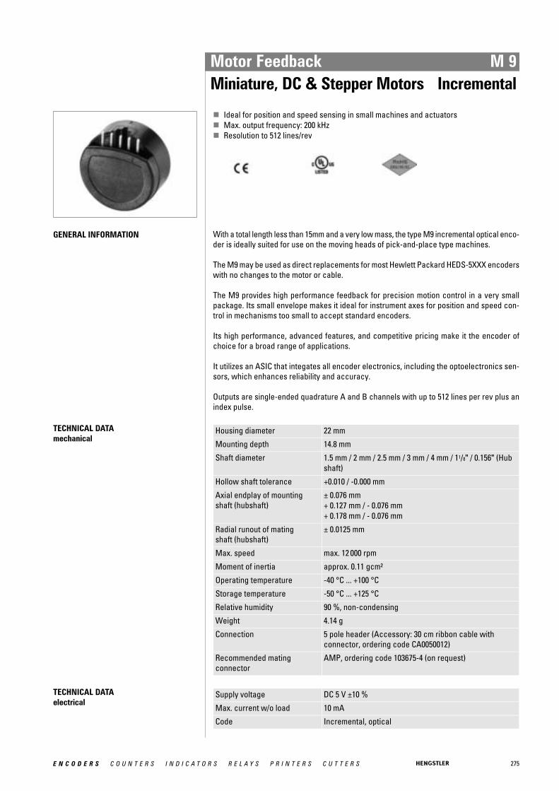
275E N C O D E R S C O U N T E R S I N D I C A T O R S R E L A Y S P R I N T E R S C U T T E R S
Motor Feedback M 9Miniature, DC & Stepper Motors Incremental
� Ideal for position and speed sensing in small machines and actuators� Max. output frequency: 200 kHz� Resolution to 512 lines/rev
GENERAL INFORMATION With a total length less than 15mm and a very low mass, the type M9 incremental optical enco-der is ideally suited for use on the moving heads of pick-and-place type machines.
The M9 may be used as direct replacements for most Hewlett Packard HEDS-5XXX encoderswith no changes to the motor or cable.
The M9 provides high performance feedback for precision motion control in a very smallpackage. Its small envelope makes it ideal for instrument axes for position and speed con-trol in mechanisms too small to accept standard encoders.
Its high performance, advanced features, and competitive pricing make it the encoder ofchoice for a broad range of applications.
It utilizes an ASIC that integates all encoder electronics, including the optoelectronics sen-sors, which enhances reliability and accuracy.
Outputs are single-ended quadrature A and B channels with up to 512 lines per rev plus anindex pulse.
TECHNICAL DATA mechanical
Housing diameter 22 mm
Mounting depth 14.8 mm
Shaft diameter 1.5 mm / 2 mm / 2.5 mm / 3 mm / 4 mm / 11/8" / 0.156" (Hubshaft)
Hollow shaft tolerance +0.010 / -0.000 mm
Axial endplay of mounting shaft (hubshaft)
± 0.076 mm+ 0.127 mm / - 0.076 mm+ 0.178 mm / - 0.076 mm
Radial runout of mating shaft (hubshaft)
± 0.0125 mm
Max. speed max. 12 000 rpm
Moment of inertia approx. 0.11 gcm²
Operating temperature -40 °C ... +100 °C
Storage temperature -50 °C ... +125 °C
Relative humidity 90 %, non-condensing
Weight 4.14 g
Connection 5 pole header (Accessory: 30 cm ribbon cable withconnector, ordering code CA0050012)
Recommended matingconnector
AMP, ordering code 103675-4 (on request)
TECHNICAL DATA electrical
Supply voltage DC 5 V ±10 %
Max. current w/o load 10 mA
Code Incremental, optical
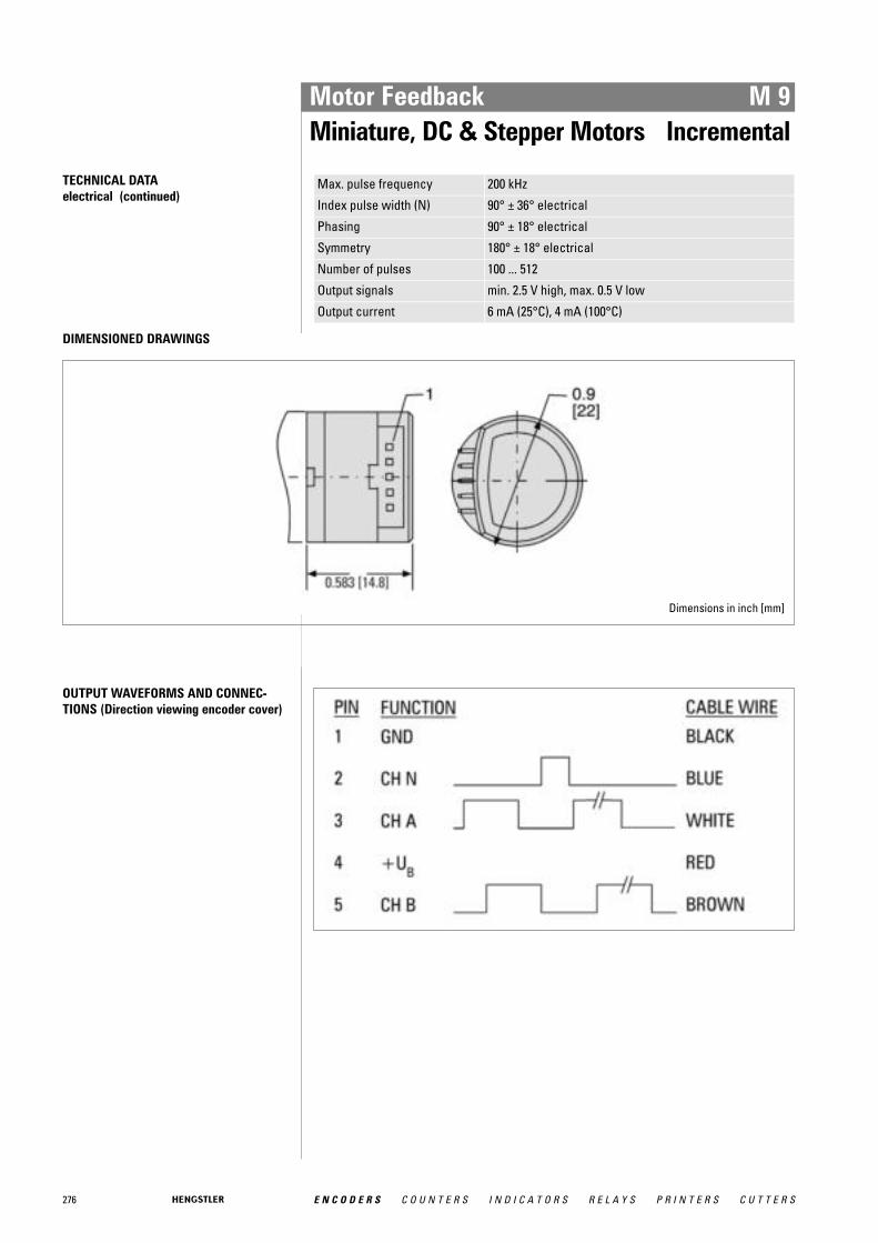
276 E N C O D E R S C O U N T E R S I N D I C A T O R S R E L A Y S P R I N T E R S C U T T E R S
Motor Feedback M 9Miniature, DC & Stepper Motors Incremental
TECHNICAL DATA electrical (continued)
Max. pulse frequency 200 kHz
Index pulse width (N) 90° ± 36° electrical
Phasing 90° ± 18° electrical
Symmetry 180° ± 18° electrical
Number of pulses 100 ... 512
Output signals min. 2.5 V high, max. 0.5 V low
Output current 6 mA (25°C), 4 mA (100°C)
DIMENSIONED DRAWINGS
Dimensions in inch [mm]
OUTPUT WAVEFORMS AND CONNEC-TIONS (Direction viewing encoder cover)
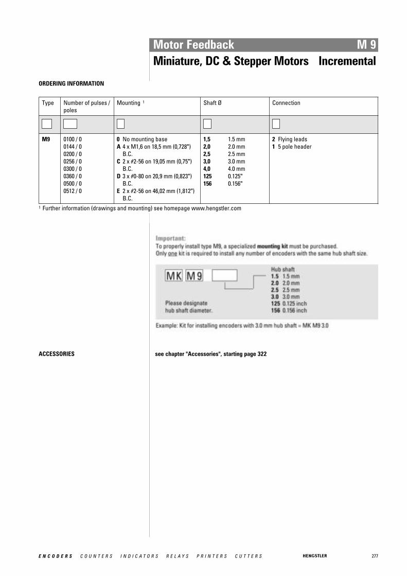
277E N C O D E R S C O U N T E R S I N D I C A T O R S R E L A Y S P R I N T E R S C U T T E R S
Motor Feedback M 9Miniature, DC & Stepper Motors Incremental
ORDERING INFORMATION
Type Number of pulses / poles
Mounting 1 Shaft Ø Connection
M9 0100 / 00144 / 00200 / 00256 / 00300 / 00360 / 00500 / 00512 / 0
0 No mounting baseA 4 x M1,6 on 18,5 mm (0,728")
B.C.C 2 x #2-56 on 19,05 mm (0,75")
B.C.D 3 x #0-80 on 20,9 mm (0,823")
B.C.E 2 x #2-56 on 46,02 mm (1,812")
B.C.
1,5 1.5 mm2,0 2.0 mm2,5 2.5 mm3,0 3.0 mm4,0 4.0 mm125 0.125"156 0.156"
2 Flying leads1 5 pole header
1 Further information (drawings and mounting) see homepage www.hengstler.com
ACCESSORIES see chapter "Accessories", starting page 322
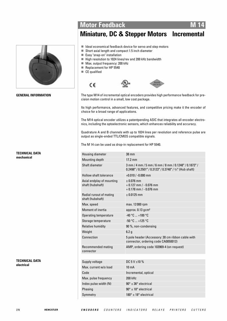
278 E N C O D E R S C O U N T E R S I N D I C A T O R S R E L A Y S P R I N T E R S C U T T E R S
Motor Feedback M 14Miniature, DC & Stepper Motors Incremental
� Ideal economical feedback device for servo and step motors� Short axial length and compact 1.5 inch diameter� Easy "snap-on" installation� High resolution to 1024 lines/rev and 200 kHz bandwidth� Max. output frequency: 200 kHz� Replacement for HP 5540� CE qualified
GENERAL INFORMATION The type M14 of incremental optical encoders provides high performance feedback for pre-cision motion control in a small, low cost package.
Its high performance, advanced features, and competitive pricing make it the encoder ofchoice for a broad range of applications.
The M14 optical encoder utilizes a patentpending ASIC that integrates all encoder electro-nics, including the optoelectronic sensors, which enhances reliability and accuracy.
Quadrature A and B channels with up to 1024 lines per revolution and reference pulse areoutput as single-ended TTL/CMOS compatible signals.
The M 14 can be used as drop-in replacement for HP 5540.
TECHNICAL DATA mechanical
Housing diameter 38 mm
Mounting depth 17.2 mm
Shaft diameter 3 mm / 4 mm / 5 mm / 6 mm / 8 mm / 0.1248" / 0.1873" /0.2498" / 0.2501" / 0.3123" / 0.3748" / 3/4" (Hub shaft)
Hollow shaft tolerance +0.010 / -0.000 mm
Axial endplay of mounting shaft (hubshaft)
± 0.076 mm+ 0.127 mm / - 0.076 mm+ 0.178 mm / - 0.076 mm
Radial runout of mating shaft (hubshaft)
± 0.0125 mm
Max. speed max. 12 000 rpm
Moment of inertia approx. 0.13 gcm²
Operating temperature -40 °C ... +100 °C
Storage temperature -50 °C ... +125 °C
Relative humidity 90 %, non-condensing
Weight 6.2 g
Connection 5 pole header (Accessory: 30 cm ribbon cable withconnector, ordering code CA0050012)
Recommended matingconnector
AMP, ordering code 103969-4 (on request)
TECHNICAL DATA electrical
Supply voltage DC 5 V ±10 %
Max. current w/o load 10 mA
Code Incremental, optical
Max. pulse frequency 200 kHz
Index pulse width (N) 90° ± 36° electrical
Phasing 90° ± 18° electrical
Symmetry 180° ± 18° electrical

279E N C O D E R S C O U N T E R S I N D I C A T O R S R E L A Y S P R I N T E R S C U T T E R S
Motor Feedback M 14Miniature, DC & Stepper Motors Incremental
TECHNICAL DATA electrical (continued)
Number of pulses 200 ... 1024
Output signals min. 2.5 V high, max. 0.5 V low
Output current 6 mA (25°C), 4 mA (100°C)
DIMENSIONED DRAWINGS
<1> Pin 1 Dimensions in inch [mm]
OUTPUT WAVEFORMS AND CONNEC-TIONS (Direction viewing encoder cover)

280 E N C O D E R S C O U N T E R S I N D I C A T O R S R E L A Y S P R I N T E R S C U T T E R S
Motor Feedback M 14Miniature, DC & Stepper Motors Incremental
ORDERING INFORMATION
Type Number of pulses / poles
Mounting 1 Shaft Ø
M14 0200 / 00400 / 00500 / 00512 / 0Higher on request
0 No mounting baseA 2 x #2-56 on 32,51 mm (1,28") B.C.B 3 x #0-80 on 20,9 mm (0,823") B.C.C 2 x #2-56 on 19,05 mm (0,75") B.C.
3,0 3.0 mm4,0 4.0 mm5,0 5 mm6,0 6 mm8,0 8 mm125 0.125"187 0.1873"249 0.2498"250 0.2501"312 0.2501"374 0.3748"375 0.3748"
1 Further information (drawings and mounting) see homepage www.hengstler.com
ACCESSORIES see chapter "Accessories", starting page 322

281E N C O D E R S C O U N T E R S I N D I C A T O R S R E L A Y S P R I N T E R S C U T T E R S
Motor Feedback Hollow Shaft EncodersAsynchronous & DC Motors Incremental
HOLLOW SHAFT ENCODER RI36-H
■ Miniature industry encoder for high numbers of pulses (5 .. 3600)■ Hollow shaft (up to 10mm)■ Short overall length■ Easy and quick mounting procedure
There are two different spring tethers availbale.
Detailed description: Page 104
HOLLOW SHAFT ENCODERS RI58-D, TD, -G, TG
■ Flexible hollow shaft design up to diameter 14 mm (-D,TD), 15mm hollow shaft (-G,TG)■ Short overall length■ Easy installation by means of clamping ring or blind shaft■ Operating temperature up to 100°C (RI58 TD and TG)■ High number of pulses (5 .. 5000) with -D■ Limited number of pulses (4 .. 2500) with TD and (50 .. 2500) with TG
The RI58 hollow shaft family offers a broad spectrum of mounting possibilities andis the right choice for all drive systems because of its high temperature option.
Detailed description of RI58-D, TD: Page 113Detailed information of RI58-G, TG Page 122
HOLLOW SHAFT ENCODER RI76TD
■ Through hollow shaft with up to diameter 42 mm■ Short overall length with an outside diameter of only 76 mm■ Easy installation by means of clamping ring■ Operating temperature up to 100 °C
Different Mounting options are available.
Detailed description: Page 132
Our hollow shaft encoder industry types are particularly suitable as a motor feedback product for asynchronous- and DC motors. Due to the partially higher requirements on theoperating temperature, there are specially developed high temperature versions (-TD) available, among certain types.
OVERWIEW
HOLLOW SHAFT ENCODER RI80-E
■ Incremental Output■ 30...45 mm hollow shaft ■ Rugged mechanical design■ Unbreakable disc■ Integrated diagnostic system■ Wide voltage range DC 5 … 30 V
The RI80-E is the first encoder using the latest Hengstler OptoAsic technology.
Detailed description: Page 136
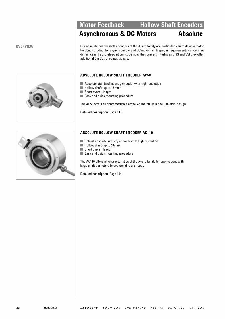
282 E N C O D E R S C O U N T E R S I N D I C A T O R S R E L A Y S P R I N T E R S C U T T E R S
Motor Feedback Hollow Shaft EncodersAsynchronous & DC Motors Absolute
ABSOLUTE HOLLOW SHAFT ENCODER AC58
■ Absolute standard industry encoder with high resolution■ Hollow shaft (up to 12 mm)■ Short overall length■ Easy and quick mounting procedure
The AC58 offers all characteristics of the Acuro family in one universal design.
Detailed description: Page 147
ABSOLUTE HOLLOW SHAFT ENCODER AC110
■ Robust absolute industry encoder with high resolution■ Hollow shaft (up to 50mm)■ Short overall length■ Easy and quick mounting procedure
The AC110 offers all characteristics of the Acuro family for applications with large shaft diameters (elevators, direct drives).
Detailed description: Page 194
Our absolute hollow shaft encoders of the Acuro family are particularly suitable as a motorfeedback product for asynchronous- and DC motors, with special requirements concerningdynamics and absolute positioning. Besides the standard interfaces BiSS and SSI they offeradditional Sin Cos of output signals.
OVERVIEW
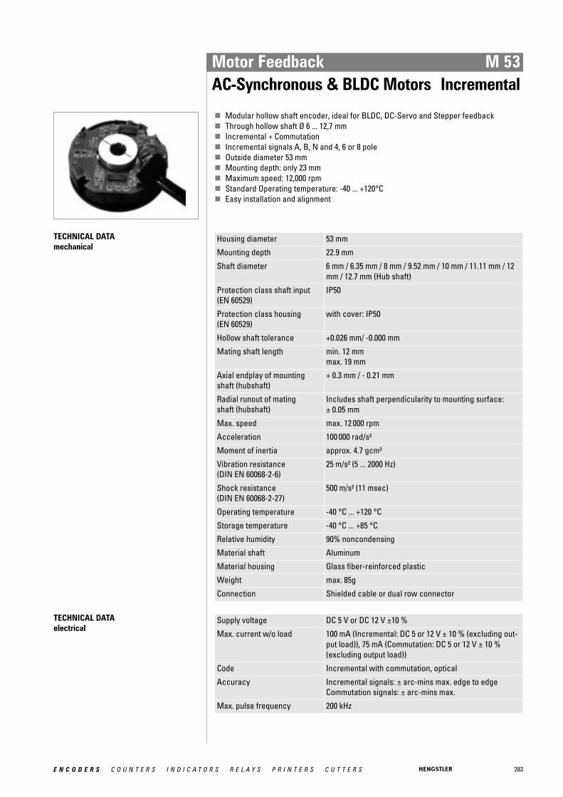
283E N C O D E R S C O U N T E R S I N D I C A T O R S R E L A Y S P R I N T E R S C U T T E R S
Motor Feedback M 53AC-Synchronous & BLDC Motors Incremental
� Modular hollow shaft encoder, ideal for BLDC, DC-Servo and Stepper feedback� Through hollow shaft Ø 6 ... 12,7 mm� Incremental + Commutation� Incremental signals A, B, N and 4, 6 or 8 pole� Outside diameter 53 mm� Mounting depth: only 23 mm� Maximum speed: 12,000 rpm� Standard Operating temperature: -40 ... +120°C� Easy installation and alignment
TECHNICAL DATA mechanical
Housing diameter 53 mm
Mounting depth 22.9 mm
Shaft diameter 6 mm / 6.35 mm / 8 mm / 9.52 mm / 10 mm / 11.11 mm / 12mm / 12.7 mm (Hub shaft)
Protection class shaft input (EN 60529)
IP50
Protection class housing (EN 60529)
with cover: IP50
Hollow shaft tolerance +0.026 mm/ -0.000 mm
Mating shaft length min. 12 mmmax. 19 mm
Axial endplay of mounting shaft (hubshaft)
+ 0.3 mm / - 0.21 mm
Radial runout of mating shaft (hubshaft)
Includes shaft perpendicularity to mounting surface: ± 0.05 mm
Max. speed max. 12 000 rpm
Acceleration 100 000 rad/s²
Moment of inertia approx. 4.7 gcm²
Vibration resistance (DIN EN 60068-2-6)
25 m/s² (5 ... 2000 Hz)
Shock resistance (DIN EN 60068-2-27)
500 m/s² (11 msec)
Operating temperature -40 °C ... +120 °C
Storage temperature -40 °C ... +85 °C
Relative humidity 90% noncondensing
Material shaft Aluminum
Material housing Glass fiber-reinforced plastic
Weight max. 85g
Connection Shielded cable or dual row connector
TECHNICAL DATA electrical
Supply voltage DC 5 V or DC 12 V ±10 %
Max. current w/o load 100 mA (Incremental: DC 5 or 12 V ± 10 % (excluding out-put load)), 75 mA (Commutation: DC 5 or 12 V ± 10 %(excluding output load))
Code Incremental with commutation, optical
Accuracy Incremental signals: ± arc-mins max. edge to edgeCommutation signals: ± arc-mins max.
Max. pulse frequency 200 kHz

284 E N C O D E R S C O U N T E R S I N D I C A T O R S R E L A Y S P R I N T E R S C U T T E R S
ORDERING INFORMATION
Type Numberof pulses
Poles commuta-tion 2
Housing Electrical 3, 4, 5 Shaft Ø Connection
M53 050005121000
0 Without4 4 pole6 6 pole8 8 pole
0 Withoutcover
2 Axial exit(for shieldedcable withpcbconnector)
1 Radial exitcover (forshieldedcable)
0 U inc = DC 5 V, output inc =NPN-O.C.
1 U inc = DC 12 V, output inc= NPN-O.C.
3 U inc = DC 5 V, output inc =RS422
6 U inc = DC 5 V, output inc =RS422, U com = DC 5 V,output com = NPN-O.C.
9 U inc = DC 5 V, output inc =RS422, U com = DC 5 V,output com = RS422
A 6.35 mm (1/4")B 6.35 mm (1/4")C 11.11 mm (7/16")D 12.7 mm (1/2")E 6 mmF 8 mmG 10 mmH 12 mm
A ... H Screened cable radial(A = 30 cm, B = 60 cm...)
1 ... 8 Dual row connectorwith mating ribboncable (1 = 30 cm, 2 = 60 cm ...)
1 allowed combinations see available combinations (pulses/poles)2 allowed combinations see available combinations (pulses/poles)3 U inc: Supply voltage incremental, U com: Supply voltage commutation (only if commutation selected)4 Code Electrical "0", "1", "3": only incremental, without commutation5 Code Electrical "6", "9": inkremental plus commutation signals6 Connection code "A" ... "H": only with output = RS 422
Motor Feedback M 53AC-Synchronous & BLDC Motors Incremental
TECHNICAL DATA electrical (continued)
Phasing Incremental signals (A leads B): 90° ± 18° electricalCommutation signals (U leads V leads W): 8 Pole: 30°, 6Pole: 60°, 4 Pole ° mechanical
Index pulse width (N) Incremental signals: 180° ± 18° electrical180° ± 36° elektrisch
Standard output versions
NPN-O.C.: A, B, NRS422: A, B, N, A, B, NNPN-O.C. (commutation): U, V, WRS422 (commutation): U, V, W, U, V, W
DIMENSIONED DRAWINGS
<1> 5/64'' (2 mm) hex key<2> cw (clockwise)<3> ccw (counter clockwise)<4> 2 x 0.125" Ø (3.2 mm) on 1.812" Ø B.C.(46 mm)<5> Mounting hole axis<6> #1 Phillips alignment screw<7> Index mark on hub
<8> for blind hub clamp screw: align index mark on hub with verticaledge on housing to properly orient hub clamp screw to hex keyaccess hole thru side of housing
<9> 80 offset between mounting hole axis and active index output (cen-tered in adjustment range)
� Index sensor positionDimensions in inch (mm)

285E N C O D E R S C O U N T E R S I N D I C A T O R S R E L A Y S P R I N T E R S C U T T E R S
Motor Feedback F 10AC-Synchronous & BLDC Motors Incremental
� Compact hollowshaft motor encoder, ideal for BLDC, DC-Servo and Stepper feedback� Through hollow shaft Ø 6 mm� Incremental signals A, B, N� Resolution up to 2048 ppr� 6 or 10 pole commutation signals� Frequency response to 300 kHz� Resolver compatible mounting� Operating temperature up to 120 °C� Mounting depth: 22.4 mm
NUMBER OF PULSES 1024, 2048; optional 6 or 10 pole commutation signals
GENERAL INFORMATION The type F10 encoder provides high performance, cost effective feedback for stepper andservo motor applications. The F10 offers compact package dimensions and flying leads fora low-profile installation. A size 10 servo ring allows easy mounting and replacement of pan-cake resolvers with high tolerance to motor shaft movement and 360 degrees of adjustmentto align the signal outputs to the shaft position.
TECHNICAL DATA mechanical
Housing diameter 31.7 mm
Mounting depth 22.5 mm
Shaft diameter 6 mm (Hub shaft)
Flange (Mounting of housing)
Servo flange
Hollow shaft tolerance +0.025 mm/ -0.000 mm (+0.001"/ -0.000")
Mounting 26.54 mm (1.045") flexible servo ring (size 10 pancakeresolver equivalent)
Axial endplay of mounting shaft (hubshaft)
± 0.25 mm
Radial runout of mating shaft (hubshaft)
Includes shaft perpendicularity to mounting surface:0.05 mm
Max. speed max. 5000 rpm (continuous), max. 12 000 rpm (short term)
Acceleration 100 000 rad/s²
Bearing life [(3.6 x 10⁹) / rpm] hours, e.g. 605 000 hours at 6000 rpm
Moment of inertia approx. 1.6 gcm²
Vibration resistance (DIN EN 60068-2-6)
2.5 g at 5 to 2000 Hz
Shock resistance (DIN EN 60068-2-27)
50 g for 6 ms duration
Operating temperature 0 °C ... +120 °C
Storage temperature 0 °C ... +120 °C
Relative humidity 90 %, non-condensing
Material shaft Brass
Material housing Cast aluminum
Material flange Aluminum
Material disk 0.76 mm thick glass
Weight approx. 45 g
Connection Flying leads

286 E N C O D E R S C O U N T E R S I N D I C A T O R S R E L A Y S P R I N T E R S C U T T E R S
Motor Feedback F 10AC-Synchronous & BLDC Motors Incremental
TECHNICAL DATA electrical
Supply voltage DC 5 V ±10 %
Max. current w/o load 100 mA (Incremental and Commutation, w/o load)
Code Incremental with commutation, optical
Accuracy Incremental signals: ±2.5 arc-mins. max. (edge to edge)Commutation signals: ±6 arc-mins. max.
Max. pulse frequency 300 kHz
Phasing Incremental signals (A leads B): A leads B by 90° for ccwshaft rotation viewing the shaft clamp end of the encoderCommutation signals (U leads V leads W): U leads Vleads W by 120°
Index to u channel ±1° mech. index pulse center to U channel edge
Index pulse width (N) 90° gated A and B low
Standard output versions
NPN-O.C. (S): A, B, NRS422: A, B, N, A, B, NNPN-O.C. (commutation): U, V, WRS422 (commutation): U, V, W, U, V, W
Number of pulses 1024, 2048
Output current Incremental: ±40 mA (RS422)Commutation: 8 mA (NPN-O.C) or ±40 mA (RS 422)
ELECTRICAL CONNECTIONS Function 1 Colour
VCC red
GND black
A blue/black
A blue
B green/black
B green
N violet/black
N violet
U brown/black
U brown
V grey/black
V grey
W white/black
W white 1 availability of function depends on version

287E N C O D E R S C O U N T E R S I N D I C A T O R S R E L A Y S P R I N T E R S C U T T E R S
Motor Feedback F 10AC-Synchronous & BLDC Motors Incremental
DIMENSIONED DRAWINGS
<1> ccw (counter clockwise) Dimensions in inch [mm]
OUTPUT WAVEFORMS

288 E N C O D E R S C O U N T E R S I N D I C A T O R S R E L A Y S P R I N T E R S C U T T E R S
Motor Feedback F 10AC-Synchronous & BLDC Motors Incremental
ORDERING INFORMATION
Type
Numberof pul-ses 1
Poles commuta-tion 2
Electrical 3, 4, 5 Shaft / bore Connection Mounting
F10 10242048
0 Without6 6 poleC 10 pole
3 U inc = DC 5 V, output inc =RS422
6 U inc = DC 5 V, output inc =RS422, U com = DC 5 V, out-put com = NPN-O.C.
9 U inc = DC 5 V, output inc =RS422, U com = DC 5 V, out-put com = RS422
4 6 mm/ through bore 0 16.5 cm flyingleads
0 Servo ringsize 10
1 allowed combinations see available combinations (pulses/poles)2 allowed combinations see available combinations (pulses/poles)3 U inc: Supply voltage incremental, U com: Supply voltage commutation (only if commutation selected)4 Code Electrical "3": only incremental, without commutation5 Code Electrical "6", "9": inkremental plus commutation signals
Available combinations (pulses/poles) Pulses ppr Number of poles
0 6 10(=C)
1024 X X X
2048 X X X
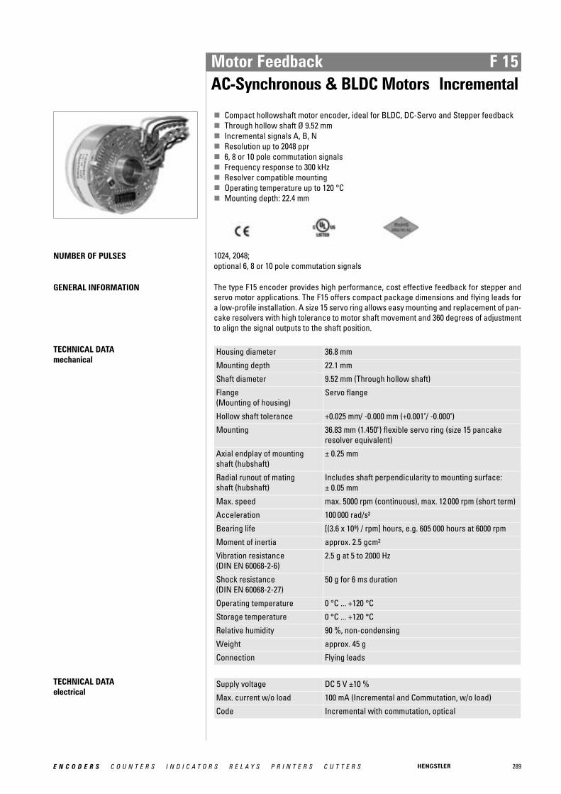
289E N C O D E R S C O U N T E R S I N D I C A T O R S R E L A Y S P R I N T E R S C U T T E R S
Motor Feedback F 15AC-Synchronous & BLDC Motors Incremental
� Compact hollowshaft motor encoder, ideal for BLDC, DC-Servo and Stepper feedback� Through hollow shaft Ø 9.52 mm� Incremental signals A, B, N� Resolution up to 2048 ppr� 6, 8 or 10 pole commutation signals� Frequency response to 300 kHz� Resolver compatible mounting� Operating temperature up to 120 °C� Mounting depth: 22.4 mm
NUMBER OF PULSES 1024, 2048; optional 6, 8 or 10 pole commutation signals
GENERAL INFORMATION The type F15 encoder provides high performance, cost effective feedback for stepper andservo motor applications. The F15 offers compact package dimensions and flying leads fora low-profile installation. A size 15 servo ring allows easy mounting and replacement of pan-cake resolvers with high tolerance to motor shaft movement and 360 degrees of adjustmentto align the signal outputs to the shaft position.
TECHNICAL DATA mechanical
Housing diameter 36.8 mm
Mounting depth 22.1 mm
Shaft diameter 9.52 mm (Through hollow shaft)
Flange (Mounting of housing)
Servo flange
Hollow shaft tolerance +0.025 mm/ -0.000 mm (+0.001"/ -0.000")
Mounting 36.83 mm (1.450") flexible servo ring (size 15 pancakeresolver equivalent)
Axial endplay of mounting shaft (hubshaft)
± 0.25 mm
Radial runout of mating shaft (hubshaft)
Includes shaft perpendicularity to mounting surface: ± 0.05 mm
Max. speed max. 5000 rpm (continuous), max. 12 000 rpm (short term)
Acceleration 100 000 rad/s²
Bearing life [(3.6 x 10⁹) / rpm] hours, e.g. 605 000 hours at 6000 rpm
Moment of inertia approx. 2.5 gcm²
Vibration resistance (DIN EN 60068-2-6)
2.5 g at 5 to 2000 Hz
Shock resistance (DIN EN 60068-2-27)
50 g for 6 ms duration
Operating temperature 0 °C ... +120 °C
Storage temperature 0 °C ... +120 °C
Relative humidity 90 %, non-condensing
Weight approx. 45 g
Connection Flying leads
TECHNICAL DATA electrical
Supply voltage DC 5 V ±10 %
Max. current w/o load 100 mA (Incremental and Commutation, w/o load)
Code Incremental with commutation, optical
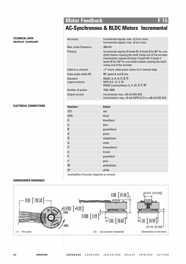
290 E N C O D E R S C O U N T E R S I N D I C A T O R S R E L A Y S P R I N T E R S C U T T E R S
Motor Feedback F 15AC-Synchronous & BLDC Motors Incremental
TECHNICAL DATA electrical (continued)
Accuracy Incremental signals: max. ±2,5 arc-mins.Incremental signals: max. ±6 arc-mins.
Max. pulse frequency 300 kHz
Phasing Incremental signals (A leads B): A leads B by 90° for ccwshaft rotation viewing the shaft clamp end of the encoderCommutation signals (U leads V leads W): U leads Vleads W by 120° for ccw shaft rotation viewing the shaftclamp end of the encoder
Index to u channel ±1° mech. index pulse center to U channel edge
Index pulse width (N) 90° gated A and B low
Standard output versions
RS422: A, B, N, A, B, NNPN-O.C.: U, V, WRS422 (commutation): U, V, W, U, V, W
Number of pulses 1024, 2048
Output current Incremental: max. ±40 mA (RS 422)Commutation: max. ±8 mA (NPN-O.C) or ±40 mA (RS 422)
ELECTRICAL CONNECTIONS Function 1 Colour
VCC red
GND black
A blue/black
A blue
B green/black
B green
N violet/black
N violet
U brown/black
U brown
V grey/black
V grey
W white/black
W white 1 availability of function depends on version
DIMENSIONED DRAWINGS
<1> Thru bore <2> ccw (counter clockwise) Dimensions in inch [mm]
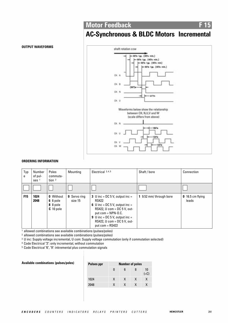
291E N C O D E R S C O U N T E R S I N D I C A T O R S R E L A Y S P R I N T E R S C U T T E R S
Motor Feedback F 15AC-Synchronous & BLDC Motors Incremental
OUTPUT WAVEFORMS
ORDERING INFORMATION
Type
Numberof pul-ses 1
Poles commuta-tion 2
Mounting Electrical 3, 4, 5 Shaft / bore Connection
F15 10242048
0 Without6 6 pole8 8 poleC 10 pole
0 Servo ringsize 15
3 U inc = DC 5 V, output inc =RS422
6 U inc = DC 5 V, output inc =RS422, U com = DC 5 V, out-put com = NPN-O.C.
9 U inc = DC 5 V, output inc =RS422, U com = DC 5 V, out-put com = RS422
1 9.52 mm/ through bore 0 16.5 cm flyingleads
1 allowed combinations see available combinations (pulses/poles)2 allowed combinations see available combinations (pulses/poles)3 U inc: Supply voltage incremental, U com: Supply voltage commutation (only if commutation selected)4 Code Electrical "3": only incremental, without commutation5 Code Electrical "6", "9": inkremental plus commutation signals
Available combinations (pulses/poles) Pulses ppr Number of poles
0 6 8 10(=C)
1024 X X X X
2048 X X X X

292 E N C O D E R S C O U N T E R S I N D I C A T O R S R E L A Y S P R I N T E R S C U T T E R S
Motor Feedback F 21AC-Synchronous & BLDC Motors Incremental
� Compact hollowshaft motor encoder, ideal for BLDC, DC-Servo and Stepper feedback� Through hollow shaft Ø 12.7 mm� Incremental signals A, B, N� Resolution up to 2048 ppr� 6, 8, 10, 12 or 16 pole commutation signals� Frequency response to 300 kHz� Resolver compatible mounting� Operating temperature up to 120 °C� Mounting depth max.: 26 mm
NUMBER OF PULSES 1024, 2048; optional 6, 8, 10, 12 or 16 pole commutation signals
GENERAL INFORMATION The type F21 encoder provides high performance, cost effective feedback for stepper andservo motor applications. The F21 offers compact package dimensions and flying leads fora low-profile installation. A size 21 servo ring allows easy mounting and replacement of pan-cake resolvers with high tolerance to motor shaft movement and 360 degrees of adjustmentto align the signal outputs to the shaft position.
TECHNICAL DATA mechanical
Housing diameter 53 mm
Mounting depth 26 mm
Shaft diameter 12.7 mm (Hub shaft)
Flange (Mounting of housing)
Servo flange
Hollow shaft tolerance +0.025 mm/ -0.000 mm (+0.001"/ -0.000")
Mounting 52.37 mm (2.062") flexible servo ring (size 21 pancakeresolver equivalent)
Axial endplay of mounting shaft (hubshaft)
± 0.25 mm
Radial runout of mating shaft (hubshaft)
Includes shaft perpendicularity to mounting surface: +0.05 mm
Max. speed max. 5000 rpm (continuous), max. 12 000 rpm (short term)
Acceleration 100 000 rad/s²
Bearing life [(3.6 x 10⁹) / rpm] hours, e.g. 605 000 hours at 6000 rpm
Moment of inertia approx. 2.5 gcm²
Vibration resistance (DIN EN 60068-2-6)
2.5 g at 5 to 2000 Hz
Shock resistance (DIN EN 60068-2-27)
50 g for 6 ms duration
Operating temperature 0 °C ... +120 °C
Storage temperature 0 °C ... +120 °C
Relative humidity 90 %, non-condensing
Material shaft Brass
Material housing Cast aluminum
Material flange Aluminum
Material disk 0.76 mm thick glass
Weight approx. 90 g
Connection Flying leads

293E N C O D E R S C O U N T E R S I N D I C A T O R S R E L A Y S P R I N T E R S C U T T E R S
Motor Feedback F 21AC-Synchronous & BLDC Motors Incremental
TECHNICAL DATA electrical
Supply voltage DC 5 V ±10 %
Max. current w/o load 100 mA (Incremental and Commutation, w/o load)
Code Incremental with commutation, optical
Accuracy Incremental signals: max. ±2,5 arc-mins.Commutation signals: max. ±6 arc-mins.
Max. pulse frequency 300 kHz
Phasing Incremental signals (A leads B): A leads B by 90° for ccwshaft rotation viewing the shaft clamp end of the encoderCommutation signals (U leads V leads W): U leads Vleads W by 120° for ccw shaft rotation viewing the shaftclamp end of the encoder
Index to u channel ±1° mech. index pulse center to U channel edge
Index pulse width (N) 90° gated A and B low
Standard output versions
RS422: A, B, N, A, B, NRS422 (commutation): U, V, W, U, V, WNPN-O.C. (commutation): U, V, W
Number of pulses 1024, 2048
Output current Incremental: ±40 mA (RS 422)Commutation: 8 mA (NPN-O.C) or ±40 mA (RS 422)
ELECTRICAL CONNECTIONS Function 1 Colour
VCC red
GND black
A blue/black
A blue
B green/black
B green
N violet/black
N violet
U brown/black
U brown
V grey/black
V grey
W white/black
W white 1 availability of function depends on version
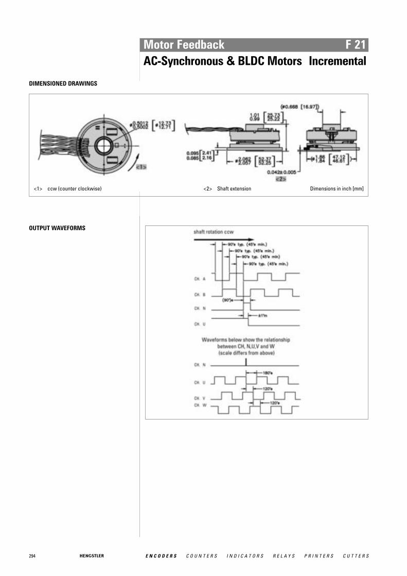
294 E N C O D E R S C O U N T E R S I N D I C A T O R S R E L A Y S P R I N T E R S C U T T E R S
Motor Feedback F 21AC-Synchronous & BLDC Motors Incremental
DIMENSIONED DRAWINGS
<1> ccw (counter clockwise) <2> Shaft extension Dimensions in inch [mm]
OUTPUT WAVEFORMS
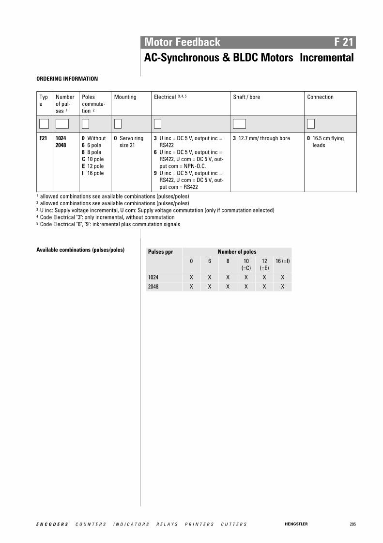
295E N C O D E R S C O U N T E R S I N D I C A T O R S R E L A Y S P R I N T E R S C U T T E R S
Motor Feedback F 21AC-Synchronous & BLDC Motors Incremental
ORDERING INFORMATION
Type
Numberof pul-ses 1
Poles commuta-tion 2
Mounting Electrical 3, 4, 5 Shaft / bore Connection
F21 10242048
0 Without6 6 pole8 8 poleC 10 poleE 12 poleI 16 pole
0 Servo ringsize 21
3 U inc = DC 5 V, output inc =RS422
6 U inc = DC 5 V, output inc =RS422, U com = DC 5 V, out-put com = NPN-O.C.
9 U inc = DC 5 V, output inc =RS422, U com = DC 5 V, out-put com = RS422
3 12.7 mm/ through bore 0 16.5 cm flyingleads
1 allowed combinations see available combinations (pulses/poles)2 allowed combinations see available combinations (pulses/poles)3 U inc: Supply voltage incremental, U com: Supply voltage commutation (only if commutation selected)4 Code Electrical "3": only incremental, without commutation5 Code Electrical "6", "9": inkremental plus commutation signals
Available combinations (pulses/poles) Pulses ppr Number of poles
0 6 8 10(=C)
12(=E)
16 (=I)
1024 X X X X X X
2048 X X X X X X

296 E N C O D E R S C O U N T E R S I N D I C A T O R S R E L A Y S P R I N T E R S C U T T E R S
Motor Feedback HC 20AC-Synchronous & BLDC Motors Incremental
� Compact hollowshaft motor encoder, ideal for BLDC, DC servo and Stepper feedback� Incremental + commutation� Phased Array Technology� Frequency response to 500 kHz� Operating temperature up to 120 °C� Outside diameter 50 mm� Cable plug-in radial/axial
500, 512, 1000, 1024, 2000, 2048, 2500; optional 4, 6 or 8 pole commutation signals
GENERAL INFORMATION The type HC20 encoder provides high performance, cost effective feedback for stepper andservo motor controls. A compliant tether allows easy mounting with high tolerance to motorshaft movement and 20 degrees of adjustment to align the signal outputs to the shaft posi-tion.
A superior optical configuration allows for generous internal component celerance elimina-ting potential damage at high ambient operating temperatures. High temperature ratedgrease is standard for extended bearing life. No special tools are required for installation.
TECHNICAL DATA mechanical
Housing diameter 50 mm
Mounting depth 36"
Shaft diameter 6 mm / 8 mm
Flange (Mounting of housing)
Tether
Mounting of shaft Front clamping ring
Protection class shaft input (EN 60529)
IP50
Protection class housing (EN 60529)
IP50
Axial endplay of mounting shaft (hubshaft)
± 0.8 mm
Radial runout of mating shaft (hubshaft)
± 0.2 mm
Max. speed max. 12 000 rpm
Operating temperature 0 °C ... +120 °C
Storage temperature -40 °C ... +120 °C
Material housing Aluminum
Material flange Aluminum
Connection Cable, axial or radial
TECHNICAL DATA electrical
Supply voltage DC 5 V ±10 %
Max. current w/o load 150 mA (incremental), 175 mA (incremental + commuta-tion)
Code Incremental with commutation, optical
Accuracy max. 40 arc-sec.
Max. pulse frequency 500 kHz

297E N C O D E R S C O U N T E R S I N D I C A T O R S R E L A Y S P R I N T E R S C U T T E R S
Motor Feedback HC 20AC-Synchronous & BLDC Motors Incremental
TECHNICAL DATA electrical (continued)
Phasing Incremental signals (A leads B): A leads B by 90° for ccwshaft rotation viewing the shaft clamp end ofCommutation signals (U leads V leads W): U leads Vleads W by 120° for ccw shaft rotation viewing the shaftclamp end of the encoder
Index pulse width (N) 90° gated A and B high
Tolerance N to U ± 1° mech. index pulse center N to U channel edge
Standard output versions
NPN-O.C.: A, B, NRS422: A, B, N, A, B, NNPN-O.C.: U, V, WRS422: U, V, W, U, V, W
DIMENSIONED DRAWINGS
Hollow shaft
Dimensions in mm
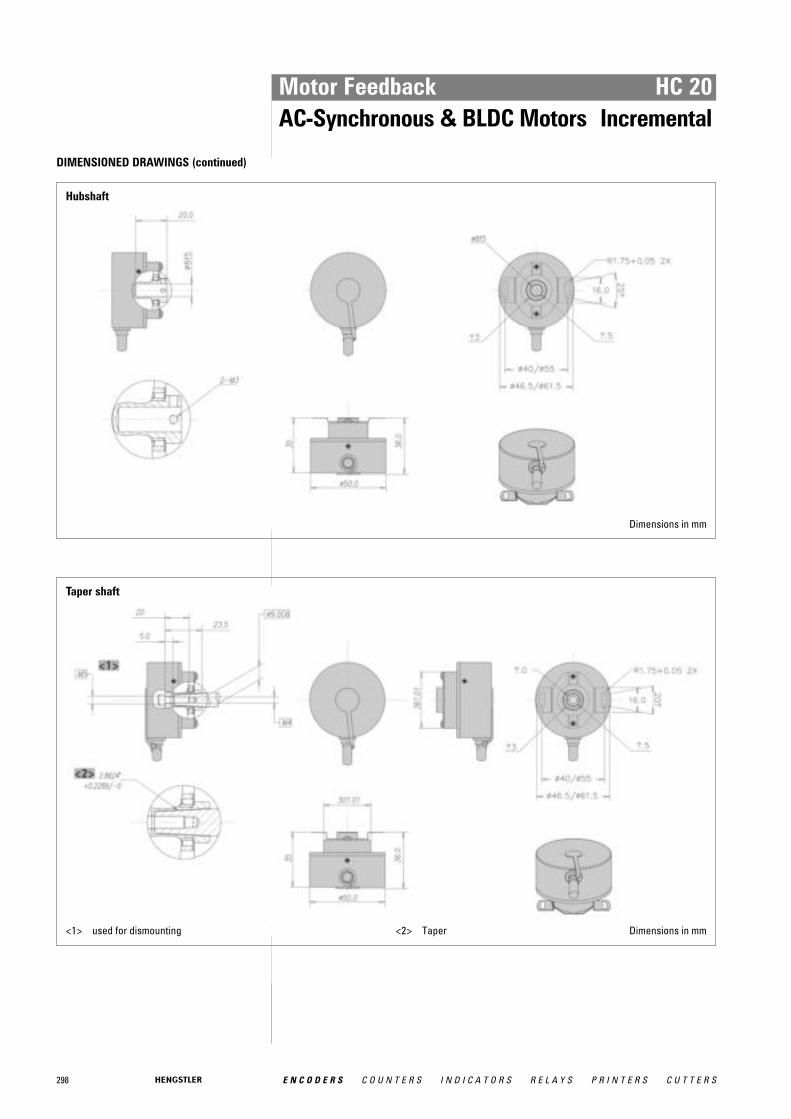
298 E N C O D E R S C O U N T E R S I N D I C A T O R S R E L A Y S P R I N T E R S C U T T E R S
Motor Feedback HC 20AC-Synchronous & BLDC Motors Incremental
DIMENSIONED DRAWINGS (continued)
Hubshaft
Dimensions in mm
Taper shaft
<1> used for dismounting <2> Taper Dimensions in mm
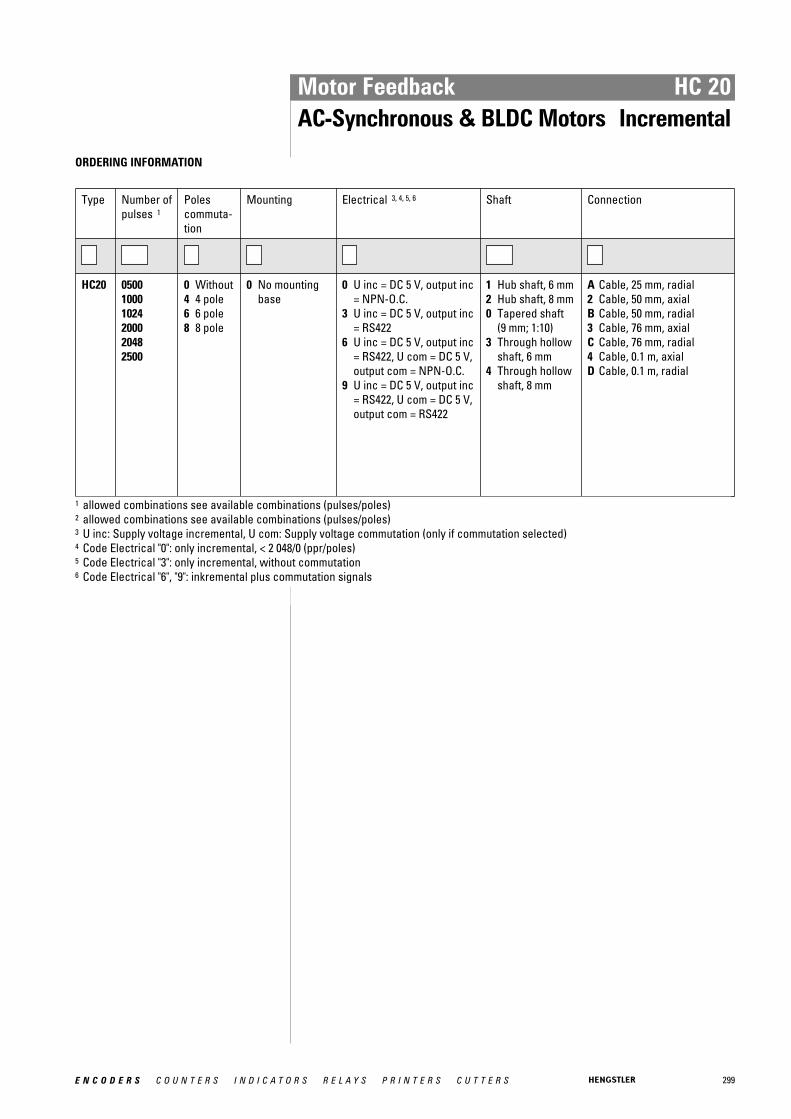
299E N C O D E R S C O U N T E R S I N D I C A T O R S R E L A Y S P R I N T E R S C U T T E R S
Motor Feedback HC 20AC-Synchronous & BLDC Motors Incremental
ORDERING INFORMATION
Type Number ofpulses 1
Poles commuta-tion
Mounting Electrical 3, 4, 5, 6 Shaft Connection
HC20 050010001024200020482500
0 Without4 4 pole6 6 pole8 8 pole
0 No mountingbase
0 U inc = DC 5 V, output inc= NPN-O.C.
3 U inc = DC 5 V, output inc= RS422
6 U inc = DC 5 V, output inc= RS422, U com = DC 5 V,output com = NPN-O.C.
9 U inc = DC 5 V, output inc= RS422, U com = DC 5 V,output com = RS422
1 Hub shaft, 6 mm2 Hub shaft, 8 mm0 Tapered shaft
(9 mm; 1:10)3 Through hollow
shaft, 6 mm4 Through hollow
shaft, 8 mm
A Cable, 25 mm, radial2 Cable, 50 mm, axialB Cable, 50 mm, radial3 Cable, 76 mm, axialC Cable, 76 mm, radial4 Cable, 0.1 m, axialD Cable, 0.1 m, radial
1 allowed combinations see available combinations (pulses/poles)2 allowed combinations see available combinations (pulses/poles)3 U inc: Supply voltage incremental, U com: Supply voltage commutation (only if commutation selected)4 Code Electrical "0": only incremental, < 2 048/0 (ppr/poles)5 Code Electrical "3": only incremental, without commutation6 Code Electrical "6", "9": inkremental plus commutation signals

300 E N C O D E R S C O U N T E R S I N D I C A T O R S R E L A Y S P R I N T E R S C U T T E R S
Motor Feedback RF 53AC-Synchronous & BLDC Motors Incremental
RF 53 with rear tether
� Solid shaft motor encoder for BLDC and gearless elevator traction machines� Incremental + commutation� Up to 10 000 ppr� Operating temperature up to 120 °C� IP54� Outside diameter 53 mm
NUMBER OF PULSES 500 to 10 000 ppr; optional 4, 6, 8, 10, 12, 16, 20, 24 or 32 pole commutation signals
TECHNICAL DATA mechanical
Housing diameter 53 mm
Shaft diameter Cone solid shaft
Flange (Mounting of housing)
Tether
Mounting of shaft Center bolt
Protection class shaft input (EN 60529)
IP54
Protection class housing (EN 60529)
IP54
Shaft load axial / radial 20 N / 90 N
Axial endplay of mounting shaft (hubshaft)
± 1.4 mm
Radial runout of mating shaft (hubshaft)
± 0.18 mm
Max. speed max. 12 000 rpm (continuous), max. 5000 rpm (short term)
Vibration resistance (DIN EN 60068-2-6)
25 m/s²
Shock resistance (DIN EN 60068-2-27)
1000 m/s²
Operating temperature -20 °C ... +120 °C
Storage temperature -40 °C ... +120 °C
Relative humidity 95 %, non-condensing
Material shaft Stainless Steel
Material housing Aluminum
Weight approx. 200 g
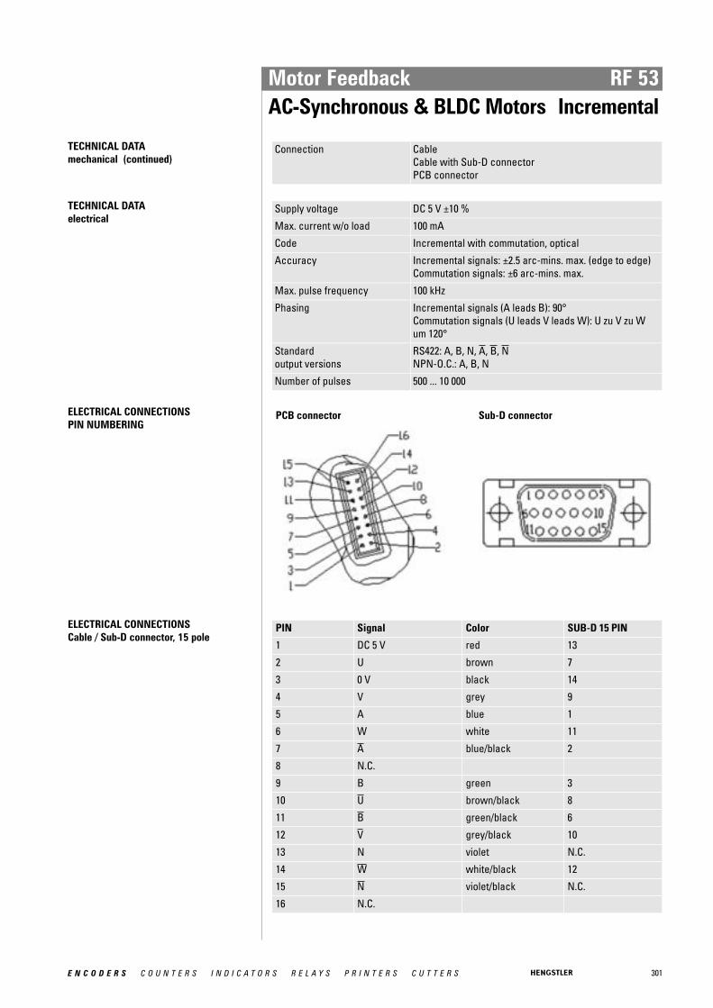
301E N C O D E R S C O U N T E R S I N D I C A T O R S R E L A Y S P R I N T E R S C U T T E R S
Motor Feedback RF 53AC-Synchronous & BLDC Motors Incremental
TECHNICAL DATA mechanical (continued)
Connection CableCable with Sub-D connectorPCB connector
TECHNICAL DATA electrical
Supply voltage DC 5 V ±10 %
Max. current w/o load 100 mA
Code Incremental with commutation, optical
Accuracy Incremental signals: ±2.5 arc-mins. max. (edge to edge)Commutation signals: ±6 arc-mins. max.
Max. pulse frequency 100 kHz
Phasing Incremental signals (A leads B): 90°Commutation signals (U leads V leads W): U zu V zu Wum 120°
Standard output versions
RS422: A, B, N, A, B, NNPN-O.C.: A, B, N
Number of pulses 500 ... 10 000
ELECTRICAL CONNECTIONSPIN NUMBERING
PCB connector Sub-D connector
ELECTRICAL CONNECTIONSCable / Sub-D connector, 15 pole
PIN Signal Color SUB-D 15 PIN
1 DC 5 V red 13
2 U brown 7
3 0 V black 14
4 V grey 9
5 A blue 1
6 W white 11
7 A blue/black 2
8 N.C.
9 B green 3
10 U brown/black 8
11 B green/black 6
12 V grey/black 10
13 N violet N.C.
14 W white/black 12
15 N violet/black N.C.
16 N.C.

302 E N C O D E R S C O U N T E R S I N D I C A T O R S R E L A Y S P R I N T E R S C U T T E R S
Motor Feedback RF 53AC-Synchronous & BLDC Motors Incremental
DIMENSIONED DRAWINGS
Front tether
<1> M6 (used for dismounting)<2> Taper<3> Internal thread M6x1 x 12 mm deep
<4> Ø 3.2 4x on a 71 mm bolt circle (B.C.)<5> Cable connector 1<6> Cable connector 2 Dimensions in mm
Rear tether
<1> M6 (used for dismounting)<2> Taper<3> 3.8 wide slot on a Ø 85 bolt circle (B.C.)
<4> M2.5 x 6 mm DP. (4x)<5> Cable connector 1<6> Cable connector 2 Dimensions in mm
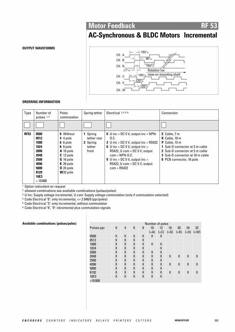
303E N C O D E R S C O U N T E R S I N D I C A T O R S R E L A Y S P R I N T E R S C U T T E R S
Motor Feedback RF 53AC-Synchronous & BLDC Motors Incremental
OUTPUT WAVEFORMS
ORDERING INFORMATION
Type Number ofpulses 1, 2
Poles commutation
Spring tether Electrical 3, 4, 5, 6 Connection
RF53 050005121000102420002048250040965000812910E3 = 10 000
0 Without4 4 pole6 6 pole8 8 poleA 10 poleC 12 poleG 16 poleK 20 poleO 24 poleW32 pole
1 Springtether rear
2 Springtetherfront
0 U inc = DC 5 V, output inc = NPN-O.C.
3 U inc = DC 5 V, output inc = RS4226 U inc = DC 5 V, output inc =
RS422, U com = DC 5 V, outputcom = NPN-O.C.
9 U inc = DC 5 V, output inc =RS422, U com = DC 5 V, outputcom = RS422
E Cable, 7 mK Cable, 10 mP Cable, 15 m1 Sub-D connector at 3 m cable2 Sub-D connector at 5 m cable3 Sub-D connector at 10 m cable0 PCB connector, 16 pole
1 Option redundant on request2 allowed combinations see available combinations (pulses/poles)3 U inc: Supply voltage incremental, U com: Supply voltage commutation (only if commutation selected)4 Code Electrical "0": only incremental, <= 2 048/0 (ppr/poles)5 Code Electrical "3": only incremental, without commutation6 Code Electrical "6", "9": inkremental plus commutation signals
Available combinations (pulses/poles) Number of poles Pulses ppr 0 4 6 8 10
(=A) 12
(=C) 16
(=G) 20
(=K) 24
(=O) 32
(=W) 0500 X X X X X X 0512 X X X X 1000 X X X X X X 1024 X X X X X 2000 X X X X X X 2048 X X X X X X X X X X 2500 X X X X X X 4096 X X X X X X X X X X 5000 X X X X X X 8192 X X X X X X X X X X 10E3 =10 000
X X X X X X
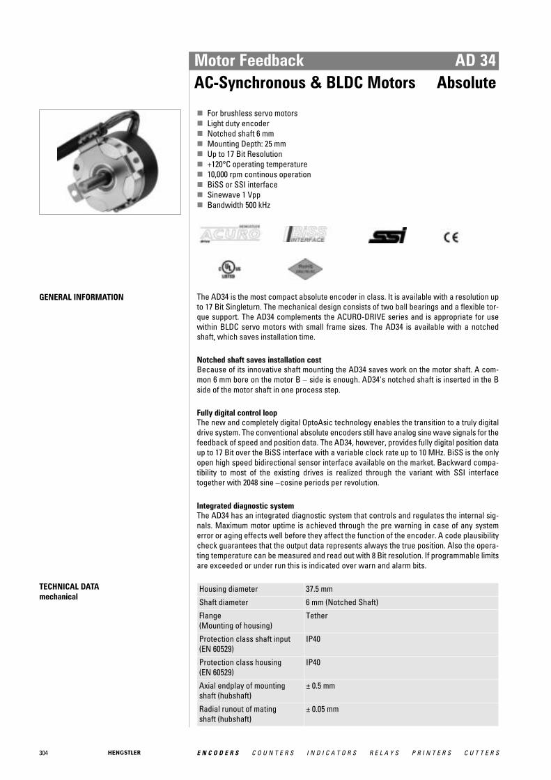
304 E N C O D E R S C O U N T E R S I N D I C A T O R S R E L A Y S P R I N T E R S C U T T E R S
Motor Feedback AD 34AC-Synchronous & BLDC Motors Absolute
� For brushless servo motors� Light duty encoder� Notched shaft 6 mm� Mounting Depth: 25 mm� Up to 17 Bit Resolution� +120°C operating temperature� 10,000 rpm continous operation� BiSS or SSI interface� Sinewave 1 Vpp� Bandwidth 500 kHz
GENERAL INFORMATION The AD34 is the most compact absolute encoder in class. It is available with a resolution upto 17 Bit Singleturn. The mechanical design consists of two ball bearings and a flexible tor-que support. The AD34 complements the ACURO-DRIVE series and is appropriate for usewithin BLDC servo motors with small frame sizes. The AD34 is available with a notchedshaft, which saves installation time.
Notched shaft saves installation cost Because of its innovative shaft mounting the AD34 saves work on the motor shaft. A com-mon 6 mm bore on the motor B − side is enough. AD34's notched shaft is inserted in the Bside of the motor shaft in one process step.
Fully digital control loop The new and completely digital OptoAsic technology enables the transition to a truly digitaldrive system. The conventional absolute encoders still have analog sine wave signals for thefeedback of speed and position data. The AD34, however, provides fully digital position dataup to 17 Bit over the BiSS interface with a variable clock rate up to 10 MHz. BiSS is the onlyopen high speed bidirectional sensor interface available on the market. Backward compa-tibility to most of the existing drives is realized through the variant with SSI interfacetogether with 2048 sine −cosine periods per revolution.
Integrated diagnostic system The AD34 has an integrated diagnostic system that controls and regulates the internal sig-nals. Maximum motor uptime is achieved through the pre warning in case of any systemerror or aging effects well before they affect the function of the encoder. A code plausibilitycheck guarantees that the output data represents always the true position. Also the opera-ting temperature can be measured and read out with 8 Bit resolution. If programmable limitsare exceeded or under run this is indicated over warn and alarm bits.
TECHNICAL DATA mechanical
Housing diameter 37.5 mm
Shaft diameter 6 mm (Notched Shaft)
Flange (Mounting of housing)
Tether
Protection class shaft input (EN 60529)
IP40
Protection class housing (EN 60529)
IP40
Axial endplay of mounting shaft (hubshaft)
± 0.5 mm
Radial runout of mating shaft (hubshaft)
± 0.05 mm
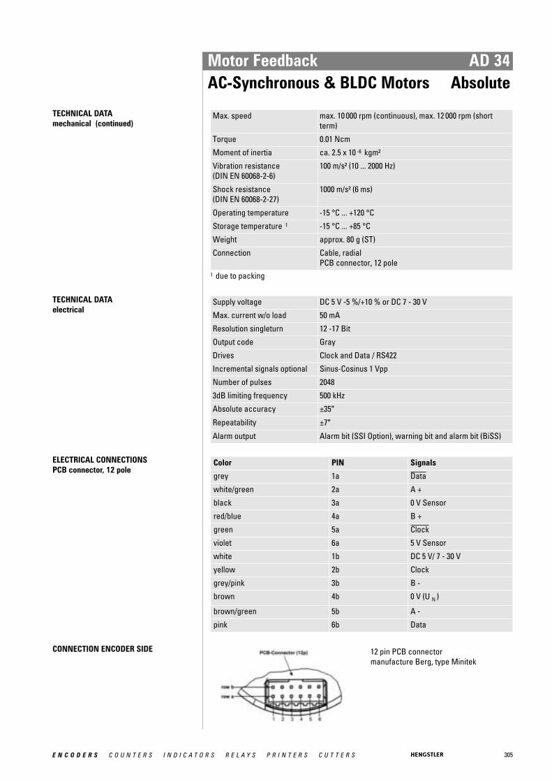
305E N C O D E R S C O U N T E R S I N D I C A T O R S R E L A Y S P R I N T E R S C U T T E R S
Motor Feedback AD 34AC-Synchronous & BLDC Motors Absolute
TECHNICAL DATA mechanical (continued)
Max. speed max. 10 000 rpm (continuous), max. 12 000 rpm (shortterm)
Torque 0.01 Ncm
Moment of inertia ca. 2.5 x 10 -6 kgm²
Vibration resistance (DIN EN 60068-2-6)
100 m/s² (10 ... 2000 Hz)
Shock resistance (DIN EN 60068-2-27)
1000 m/s² (6 ms)
Operating temperature -15 °C ... +120 °C
Storage temperature 1 -15 °C ... +85 °C
Weight approx. 80 g (ST)
Connection Cable, radialPCB connector, 12 pole
1 due to packing
TECHNICAL DATA electrical
Supply voltage DC 5 V -5 %/+10 % or DC 7 - 30 V
Max. current w/o load 50 mA
Resolution singleturn 12 -17 Bit
Output code Gray
Drives Clock and Data / RS422
Incremental signals optional Sinus-Cosinus 1 Vpp
Number of pulses 2048
3dB limiting frequency 500 kHz
Absolute accuracy ±35"
Repeatability ±7"
Alarm output Alarm bit (SSI Option), warning bit and alarm bit (BiSS)
ELECTRICAL CONNECTIONSPCB connector, 12 pole
Color PIN Signals
grey 1a Data
white/green 2a A +
black 3a 0 V Sensor
red/blue 4a B +
green 5a Clock
violet 6a 5 V Sensor
white 1b DC 5 V/ 7 - 30 V
yellow 2b Clock
grey/pink 3b B -
brown 4b 0 V (U N )
brown/green 5b A -
pink 6b Data
CONNECTION ENCODER SIDE 12 pin PCB connector manufacture Berg, type Minitek
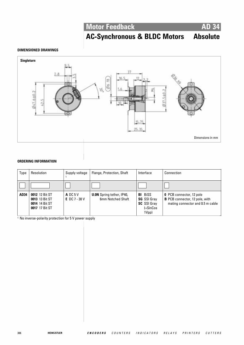
306 E N C O D E R S C O U N T E R S I N D I C A T O R S R E L A Y S P R I N T E R S C U T T E R S
Motor Feedback AD 34AC-Synchronous & BLDC Motors Absolute
DIMENSIONED DRAWINGS
Singleturn
Dimensions in mm
ORDERING INFORMATION
Type Resolution Supply voltage1
Flange, Protection, Shaft Interface Connection
AD34 0012 12 Bit ST0013 13 Bit ST0014 14 Bit ST0017 17 Bit ST
A DC 5 VE DC 7 - 30 V
U.0N Spring tether, IP40,6mm Notched Shaft
BI BiSSSG SSI GraySC SSI Gray
(+SinCos1Vpp)
0 PCB connector, 12 poleB PCB connector, 12 pole, with
mating connector and 0.5 m cable
1 No inverse-polarity protection for 5 V power supply

307E N C O D E R S C O U N T E R S I N D I C A T O R S R E L A Y S P R I N T E R S C U T T E R S
Motor Feedback AD 35AC-Synchronous & BLDC Motors Absolute
� Shortes absolute encoder world wide� Mounting depth: 23.65 mm� Hub shaft 8 mm� Resolution up to 22 Bit Singleturn� +120°C operating temperature� 10,000 rpm continous operation� BiSS or SSI interface� Bandwidth 500kHz
GENERAL INFORMATION Hengstler presents the shortest hollowshaft encoder world wide: The AD35. It is availablewith a 8 mm hub shaft and and a resolution up to 22 Bit Singleturn. The mechanical designconsists of two ball bearings and a flexible torque support. The AD35 complements theACURO-DRIVE series and is appropriate for use within BLDC servo motors with small framesizes.
Further fields of Application: • Medical • Measuring instrument • Military • Robotics
Fully digital control loop The new and completely digital OptoAsic technology enables the transition to a truly digitaldrive system. The conventional absolute encoders still have analog sine wave signals for thefeedback of speed and position data. The AD35, however, provides fully digital position dataup to 22 Bit over the BiSS interface with a variable clock rate up to 10 MHz. BiSS is the onlyopen high speed bidirectional sensor interface available on the market. Backward compa-tibility to most of the existing drives is realized through the variant with SSI interfacetogether with 2048 sine −cosine periods per revolution.
Integrated diagnostic system The AD35 has an integrated diagnostic system that controls and regulates the internal sig-nals. Maximum motor uptime is achieved through the pre warning in case of any systemerror or aging effects well before they affect the function of the encoder. A code plausibilitycheck guarantees that the output data represents always the true position. Also the opera-ting temperature can be measured and read out with 8 Bit resolution. If programmable limitsare exceeded or under run this is indicated over warn and alarm bits.
TECHNICAL DATA mechanical
Housing diameter 37.5 mm
Shaft diameter 8 mm (Hubshaft)
Flange (Mounting of housing)
Tether
Protection class shaft input (EN 60529)
IP40
Protection class housing (EN 60529)
IP40
Axial endplay of mounting shaft (hubshaft)
± 0.5 mm

308 E N C O D E R S C O U N T E R S I N D I C A T O R S R E L A Y S P R I N T E R S C U T T E R S
Motor Feedback AD 35AC-Synchronous & BLDC Motors Absolute
TECHNICAL DATA mechanical (continued)
Radial runout of mating shaft (hubshaft)
± 0.05 mm
Max. speed max. 10 000 rpm (continuous), max. 12 000 rpm (shortterm)
Torque 0.01 Ncm
Moment of inertia ca. 2.5 x 10 -6 kgm²
Vibration resistance (DIN EN 60068-2-6)
100 m/s² (10 ... 2000 Hz)
Shock resistance (DIN EN 60068-2-27)
1000 m/s² (6 ms)
Operating temperature -15 °C ... +120 °C
Storage temperature 1 -15 °C ... +85 °C
Material housing Plastic
Weight approx. 80 g (ST)
Connection Cable, radialPCB connector, 12 pole
1 due to packing
TECHNICAL DATA electrical
Supply voltage DC 5 V -5 %/+10 % or DC 7 - 30 V
Max. current w/o load 50 mA
Resolution singleturn 12 - 22 Bit
Resolution multiturn 12 Bit
Output code Gray
Drives Clock and Data / RS422
Incremental signals optional Sinus-Cosinus 1 Vpp
Number of pulses 2048
3dB limiting frequency 500 kHz
Absolute accuracy ±35"
Repeatability ±7"
Alarm output Alarm bit (SSI Option), warning and alarm bit (BiSS)
ELECTRICAL CONNECTIONSPCB connector, 12 pole
Color PIN Signals
grey 1a Data
white/green 2a A +
black 3a 0 V Sensor
red/blue 4a B +
green 5a Clock
violet 6a 5 V Sensor
white 1b DC 5 V/ 7 - 30 V
yellow 2b Clock
grey/pink 3b B -
brown 4b 0 V (U N )
brown/green 5b A -
pink 6b Data

309E N C O D E R S C O U N T E R S I N D I C A T O R S R E L A Y S P R I N T E R S C U T T E R S
Motor Feedback AD 35AC-Synchronous & BLDC Motors Absolute
CONNECTION ENCODER SIDE 12 pin PCB connector manufacture Berg, type Minitek
DIMENSIONED DRAWINGS
<1> Basis shaft<2> Screw DIN EN ISO 4762, mounting torque 2 Nm Dimensions in mm
ORDERING INFORMATION
Type Resolution Supply voltage1
Flange, Protection, Shaft Interface Connection
AD35 0012 12 Bit ST0013 13 Bit ST0014 14 Bit ST0017 17 Bit ST0019 19 Bit ST
(BiSS)0022 22 Bit ST
(BiSS)
A DC 5 VE DC 7 - 30 V
F.0R Spring tether, IP40, 8mm hub shaft
BI BiSSSG SSI GraySC SSI Gray
(+SinCos1Vpp)
0 PCB connector, 12 poleB PCB connector, 12 pole, with
mating connector and 0.5 m cable
1 No inverse-polarity protection for 5 V power supply

310 E N C O D E R S C O U N T E R S I N D I C A T O R S R E L A Y S P R I N T E R S C U T T E R S
Motor Feedback AD 36AC-Synchronous & BLDC Motors Absolute
� For brushless servo motors� Resolver size 15 compatible� Through hollow shaft 8 mm� 19 Bit Singleturn + 12 Bit Multiturn� +120°C operating temperature� 10,000 rpm continous operation� Optical encoder with a true geared multiturn� BiSS or SSI interface� Sinewave 1 Vpp� Bandwidth 500 kHz
GENERAL INFORMATION The AD36 is an absolute encoder with a true geared Multiturn, optical sensing technologyand 36 mm diameter. Unique is the through hollow shaft which enables an assembly that iscompatible with resolver size 15. The mechanical design consists of two ball bearings anda flexible torque support. The AD36 complements the ACURO-DRIVE series and is appro-priate for use within BLDC servo motors with small frame sizes.
Fully digital control loop The new and completely digital OptoAsic technology enables the transition to a truly digitaldrive system. The conventional absolute encoders still have analog sine wave signals for thefeedback of speed and position data. The AD36, however, provides fully digital position dataup to 19 Bit (Singleturn) and 12 Bit (Multiturn) over the BiSS interface with a variable clockrate up to 10 MHz. BiSS is the only open high speed bidirectional sensor interface availableon the market. Backward compatibility to most of the existing drives is realized through thevariant with SSI interface together with 2048 sine −cosine periods per revolution.
Integrated diagnostic system The AD36 has an integrated diagnostic system that controls and regulates the internal sig-nals. Maximum motor uptime is achieved through the pre warning in case of any systemerror or aging effects well before they affect the function of the encoder. A code plausibilitycheck guarantees that the output data represents always the true position. Also the opera-ting temperature can be measured and read out with 8 Bit resolution. If programmable limitsare exceeded or under run this is indicated over warn and alarm bits.
TECHNICAL DATA mechanical
Housing diameter 37.5 mm
Shaft diameter 8 mm (Through hollow shaft)8 mm (Hubshaft)
Flange (Mounting of housing)
Tether
Protection class shaft input (EN 60529)
IP40
Protection class housing (EN 60529)
IP40
Axial endplay of mounting shaft (hubshaft)
± 0.5 mm
Radial runout of mating shaft (hubshaft)
± 0.05 mm
Max. speed max. 10 000 rpm (continuous), max. 12 000 rpm (shortterm)
Torque 0.01 Ncm

311E N C O D E R S C O U N T E R S I N D I C A T O R S R E L A Y S P R I N T E R S C U T T E R S
Motor Feedback AD 36AC-Synchronous & BLDC Motors Absolute
TECHNICAL DATA mechanical (continued)
Moment of inertia ca. 2.5 x 10 -6 kgm²
Vibration resistance (DIN EN 60068-2-6)
100 m/s² (10 ... 2000 Hz)
Shock resistance (DIN EN 60068-2-27)
1000 m/s² (6 ms)
Operating temperature -15 °C ... +120 °C
Storage temperature 1 -15 °C ... +85 °C
Weight approx. 80 g (ST) / 130 g (MT)
Connection Cable, radialPCB connector, 12 pole
1 due to packing
TECHNICAL DATA electrical
Supply voltage DC 5 V -5 %/+10 % or DC 7 - 30 V
Max. current w/o load 50 mA (ST), 100 mA (MT)
Resolution singleturn 12 - 19 Bit (BiSS)12 - 17 Bit (SSI)
Resolution multiturn 12 Bit
Output code Gray
Drives Clock and Data / RS422
Incremental signals optional Sinus-Cosinus 1 Vpp
Number of pulses 2048
3dB limiting frequency 500 kHz
Absolute accuracy ±35"
Repeatability ±7"
Alarm output Alarm bit (SSI Option), warning and alarm bit (BiSS)
ELECTRICAL CONNECTIONSPCB connector, 12 pole
Color PIN Signals
grey 1a Data
white/green 2a A +
black 3a 0 V Sensor
red/blue 4a B +
green 5a Clock
violet 6a 5 V Sensor
white 1b DC 5 V/ 7 - 30 V
yellow 2b Clock
grey/pink 3b B -
brown 4b 0 V (U N )
brown/green 5b A -
pink 6b Data
CONNECTION ENCODER SIDE 12 pin PCB connector manufacture Berg, type Minitek
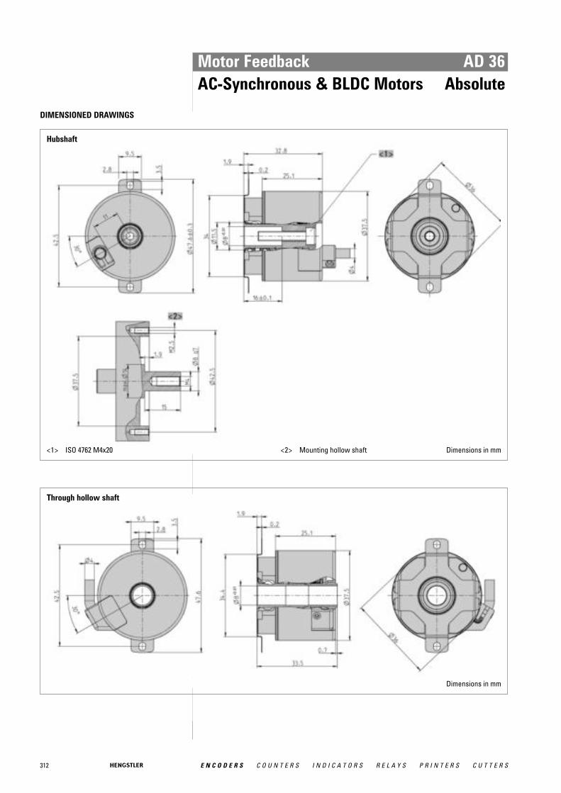
312 E N C O D E R S C O U N T E R S I N D I C A T O R S R E L A Y S P R I N T E R S C U T T E R S
Motor Feedback AD 36AC-Synchronous & BLDC Motors Absolute
DIMENSIONED DRAWINGS
Hubshaft
<1> ISO 4762 M4x20 <2> Mounting hollow shaft Dimensions in mm
Through hollow shaft
Dimensions in mm
313E N C O D E R S C O U N T E R S I N D I C A T O R S R E L A Y S P R I N T E R S C U T T E R S
Motor Feedback AD 36AC-Synchronous & BLDC Motors Absolute
ORDERING INFORMATION
Type Resolution Supply vol-tage
Flange, Protection, Shaft Interface Connection
AD36 0012 12 Bit ST0013 13 Bit ST0014 14 Bit ST0017 17 Bit ST0019 19 Bit ST (BiSS)1213 12 Bit MT + 13 Bit ST1217 12 Bit MT + 17 Bit ST1219 12 Bit MT + 19 Bit ST
(BiSS)
A DC 5 VE DC 7 - 30 V
F.0C Spring tether, IP40, 8 mmtrough hollow shaft
F.0R Spring tether, IP40, 8 mmhub shaft
BI BiSSSC SSI Gray
(+SinCos1Vpp)
0 PCB connector, 12pole
B PCB connector, 12pole, with matingconnector and 0.5 mcable
ACCESSORIES see chapter "Accessories", starting page 322

314 E N C O D E R S C O U N T E R S I N D I C A T O R S R E L A Y S P R I N T E R S C U T T E R S
Motor Feedback AD 58AC-Synchronous & BLDC Motors Absolute
� For brushless servo motors� All-digital and highspeed� +120°C operating temperature� 10,000 rpm continous operation� Optical encoder with a true geared multiturn� BiSS or SSI interface� Option Sinewave 1 Vpp: Harmonic distortion less than 1%� Bandwidth 500 kHz
GENERAL INFORMATION The AD58 is an absolute encoder with a true geared Multiturn and optical sensing techno-logy: The mechanical design consists of two ball bearings and a flexible torque support. TheAD58 is ideally suited for integration into BLDC servo motors for demanding applicationssuch as CNC precision machining and printing in professionell quality. Through its low cur-rent consumption the AD58 is contributing to lowering cost of ownership.
Fully digital control loop The new and completely digital OptoAsic technology enables the transition to a truly digitaldrive system. The conventional absolute encoders still have analog sine wave signals for thefeedback of speed and position data. The AD 58, however, provides fully digital position dataup to 22 Bit (Singleturn) and 12 Bit (Multiturn) over the BiSS interface with a variable clockrate up to 10 MHz. This corresponds a singleturn resolution of morethan 4 million measuredsteps.
TECHNICAL DATA mechanical
Housing diameter 58 mm
Shaft diameter 10 mm (Cone hollow shaft)10 mm (Cone solid shaft)
Flange (Mounting of housing)
Tether
Protection class shaft input (EN 60529)
IP40
Protection class housing (EN 60529)
IP40
Axial endplay of mounting shaft (hubshaft)
± 0.5 mm
Radial runout of mating shaft (hubshaft)
± 0.1 mm
Max. speed max. 10 000 rpm (continuous), max. 12 000 rpm (shortterm)
Torque 0.01 Ncm
Moment of inertia ca. 3.8 x 10 -6 kgm²
Vibration resistance (DIN EN 60068-2-6)
100 m/s² (10 ... 2000 Hz)
Shock resistance (DIN EN 60068-2-27)
1000 m/s² (6 ms)
Operating temperature -15 °C ... +120 °C
Storage temperature 1 -15 °C ... +85 °C
Weight approx. 260 g (ST) / 310 g (MT)
Connection PCB connector, 12 pole

315E N C O D E R S C O U N T E R S I N D I C A T O R S R E L A Y S P R I N T E R S C U T T E R S
Motor Feedback AD 58AC-Synchronous & BLDC Motors Absolute
TECHNICAL DATA mechanical (continued)
1 due to packing
TECHNICAL DATA electrical
Supply voltage ± 10% DC 5 V or DC 10 - 30 V
Max. current w/o load 50 A (ST), 100 A (MT)
Resolution singleturn 13 Bit (SSI)max. 22 Bit (BiSS)
Resolution multiturn 12 Bit
Output code Binary, Gray
Incremental signals optional Sinus-Cosinus 1 Vpp
Number of pulses 2048
3dB limiting frequency 500 kHz
Absolute accuracy ±35"
Repeatability ±7"
Parametrization Resolution, Code type, Direction, Warning, Alarm
Alarm output Alarm bit (SSI Option), warning and alarm bit (BiSS)
ELECTRICAL CONNECTIONSPCB connector, 12 pole
Colour PIN Signals
violet 1a Data
green 2a A+
brown/green 3a 0 V Sensor
blue 4a B+
brown 5a Clock
red//blue 6a 5 V Sensor
green/pink 1b DC 5 V/ 7 -30 V
white 2b Clock
red 3b B-
white/green 4b 0 V (U N )
yellow 5b A-
black 6b Data
CONNECTION ENCODER SIDE 12 pin PCB connector manufacture Berg, type Minitek Screen is connected over a length of 10 mm with encoder housing.
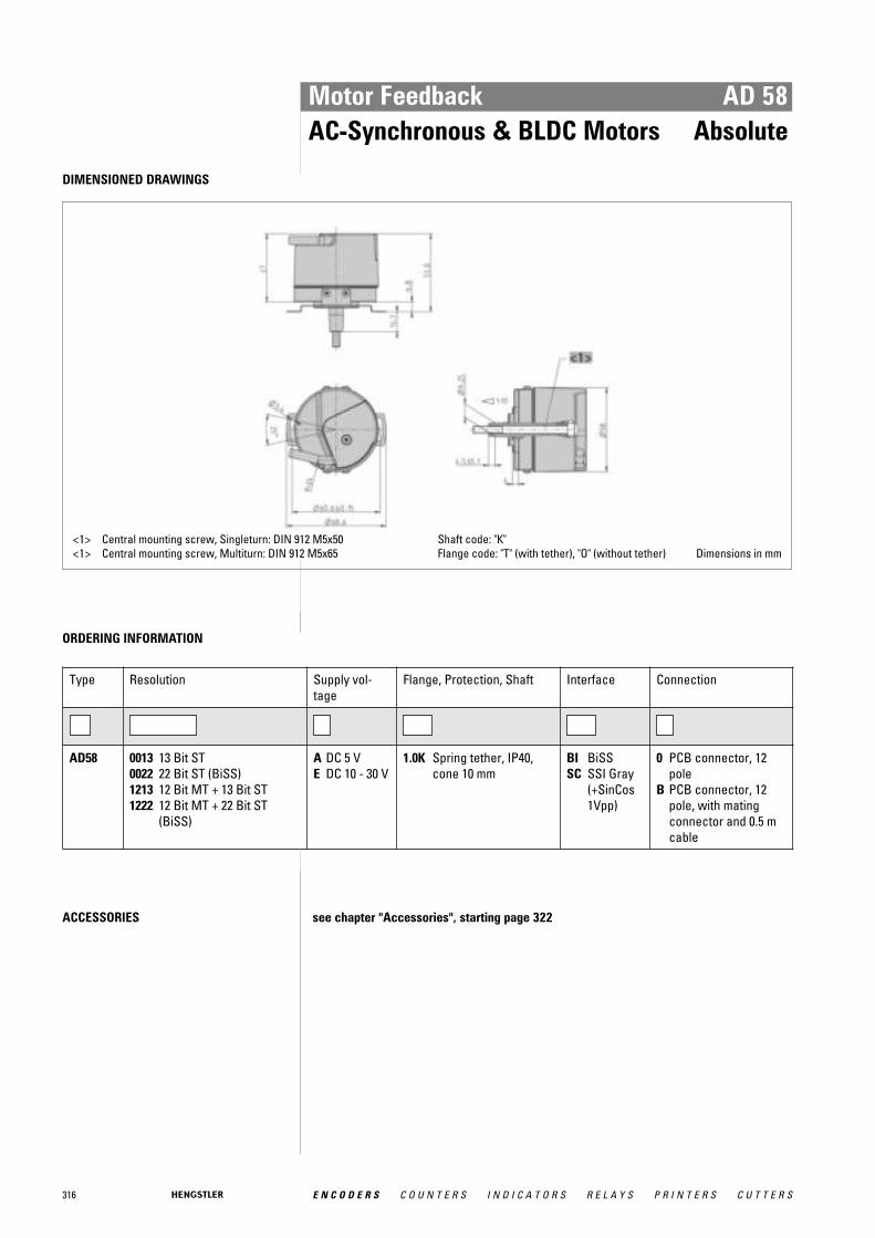
316 E N C O D E R S C O U N T E R S I N D I C A T O R S R E L A Y S P R I N T E R S C U T T E R S
Motor Feedback AD 58AC-Synchronous & BLDC Motors Absolute
DIMENSIONED DRAWINGS
<1> Central mounting screw, Singleturn: DIN 912 M5x50<1> Central mounting screw, Multiturn: DIN 912 M5x65
Shaft code: "K"Flange code: "T" (with tether), "O" (without tether) Dimensions in mm
ORDERING INFORMATION
Type Resolution Supply vol-tage
Flange, Protection, Shaft Interface Connection
AD58 0013 13 Bit ST0022 22 Bit ST (BiSS)1213 12 Bit MT + 13 Bit ST1222 12 Bit MT + 22 Bit ST
(BiSS)
A DC 5 VE DC 10 - 30 V
1.0K Spring tether, IP40,cone 10 mm
BI BiSSSC SSI Gray
(+SinCos1Vpp)
0 PCB connector, 12pole
B PCB connector, 12pole, with matingconnector and 0.5 mcable
ACCESSORIES see chapter "Accessories", starting page 322

317E N C O D E R S C O U N T E R S I N D I C A T O R S R E L A Y S P R I N T E R S C U T T E R S
Motor Feedback S 21AC-Synchronous & BLDC Motors Sine-wave
� Wide operating temperature range of −15 °C up to +120 °C, therefore optimum use ofmotor capacity
� High limiting frequency with excellent signal quality, allowing highest peak speeds andreduced non-productive time wastage
� Excellent immunity to interference (EN 61000-4-4, Class 4)� High functional safety due to signal control and system monitoring (under-voltage, pol-
lution, disc damage, end of LED service life)� High signal quality through control and error compensation
TECHNICAL DATA mechanical
Housing diameter 53 mm
Shaft diameter Cone 1/10
Protection class shaft input (EN 60529)
IP40
Protection class housing (EN 60529)
IP40
Shaft load axial / radial for tapered solid shaft: 20 N / 90 N
Axial endplay of mounting shaft (hubshaft)
± 0.5 mm
Radial runout of mating shaft (hubshaft)
± 0.1 mm
Max. speed max. 12 000 rpm (continuous), max. 15 000 rpm (shortterm)
Torque ≤ 1 Ncm
Vibration resistance (DIN EN 60068-2-6)
≤ 100 m/s² (10 ... 2,000 Hz)
Shock resistance (DIN EN 60068-2-27)
≤ 1,000 m/s² (6 ms)
Operating temperature -15 °C ... +120 °C
Storage temperature -20 °C ... +80 °C
Material housing Aluminum
Weight approx. 170 g
Connection PCB connector and cable
TECHNICAL DATA electrical
General design as per DIN EN 61010-1, protection class III, contamina-tion level 2, overvoltage class II
Supply voltage DC 5 V ±10 %
Max. current w/o load 120 mA
Reference signal R > 0.4 V (1 pulse per revolution)
Commutation signals C, D Sine - Cosine 1 Vpp (1 period per rev.)
Incremental signals optional Sinus-Cosinus 1 Vpp
Number of pulses 2048
3dB limiting frequency 500 kHz
Absolute accuracy ±35"
Repeatability ±7"
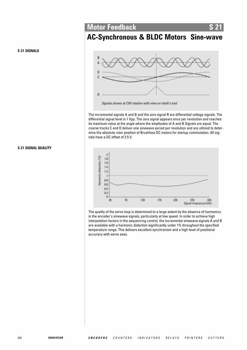
318 E N C O D E R S C O U N T E R S I N D I C A T O R S R E L A Y S P R I N T E R S C U T T E R S
Motor Feedback S 21AC-Synchronous & BLDC Motors Sine-wave
S 21 SIGNALS
The incremental signals A and B and the zero signal R are differential voltage signals. Thedifferential signal level is 1 Vpp. The zero signal appears once per revolution and reachesits maximum value at the angle where the amplitudes of A and B Signals are equal. Thecoarse tracks C and D deliver one sinewave period per revolution and are utilized to deter-mine the absolute rotor position of Brushless DC motors for startup commutation. All sig-nals have a DC offset of 2.5 V.
S 21 SIGNAL QUALITY
The quality of the servo loop is determined to a large extent by the absence of harmonicsin the encoder's sinewave signals, particularly at low speed. In order to achieve highinterpolation factors in the sequencing control, the incremental sinewave signals A and Bare available with a harmonic distortion significantly under 1% throughout the specifiedtemperature range. This delivers excellent synchronism and a high level of positionalaccuracy with servo axes.
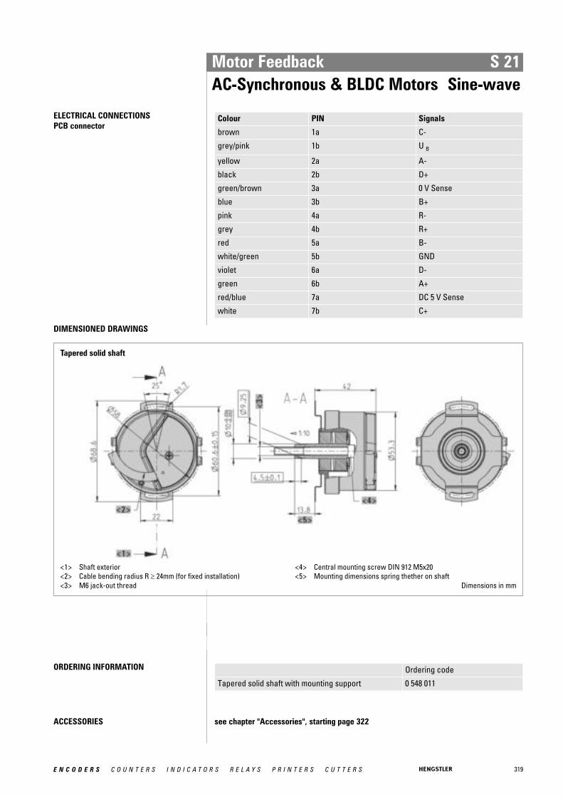
319E N C O D E R S C O U N T E R S I N D I C A T O R S R E L A Y S P R I N T E R S C U T T E R S
Motor Feedback S 21AC-Synchronous & BLDC Motors Sine-wave
ELECTRICAL CONNECTIONSPCB connector
Colour PIN Signals
brown 1a C-
grey/pink 1b U B
yellow 2a A-
black 2b D+
green/brown 3a 0 V Sense
blue 3b B+
pink 4a R-
grey 4b R+
red 5a B-
white/green 5b GND
violet 6a D-
green 6b A+
red/blue 7a DC 5 V Sense
white 7b C+
DIMENSIONED DRAWINGS
Tapered solid shaft
<1> Shaft exterior<2> Cable bending radius R ≥ 24mm (for fixed installation)<3> M6 jack-out thread
<4> Central mounting screw DIN 912 M5x20<5> Mounting dimensions spring thether on shaft
Dimensions in mm
ORDERING INFORMATION Ordering code
Tapered solid shaft with mounting support 0 548 011
ACCESSORIES see chapter "Accessories", starting page 322
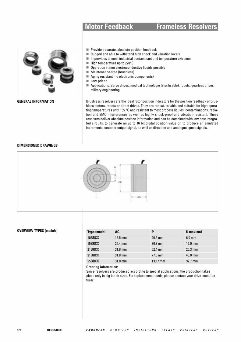
320 E N C O D E R S C O U N T E R S I N D I C A T O R S R E L A Y S P R I N T E R S C U T T E R S
Motor Feedback Frameless Resolvers
� Provide accurate, absolute position feedback� Rugged and able to withstand high shock and vibration levels� Impervious to most industrial contaminant and temperature extremes� High temperature up to 220°C� Operation in non electroconductive liquids possible� Maintenance-free (brushless)� Aging resistant (no electronic components)� Low-priced� Applications: Servo drives, medical technologie (sterilisable), robots, gearless drives,
military engineering
GENERAL INFORMATION Brushless resolvers are the ideal rotor position indicators for the position feedback of brus-hless motors, robots or direct drives. They are robust, reliable and suitable for high opera-ting temperatures until 155 °C and resistant to most process liquids, contaminations, radia-tion and EMC-Interferences as well as highly shock-proof and vibration-resistant. Theseresolvers deliver absolute position information and can be combined with low cost integra-ted circuits, to generate an up to 16 bit digital position-value or, to produce an emulatedincremental encoder output signal, as well as direction and analogue speedsignals.
DIMENSIONED DRAWINGS
OVERVIEW TYPES (models) Type (model) AG P U maximal
10BRCX 16.5 mm 26.5 mm 6.0 mm
15BRCX 25.4 mm 36.8 mm 12.0 mm
21BRCX 31.8 mm 52.4 mm 20.3 mm
31BRCX 31.8 mm 77.5 mm 40.0 mm
55BRCX 31.8 mm 139.7 mm 92.7 mm
Ordering information: Since resolvers are produced according to special applications, the production takesplace only in big batch sizes. For replacement needs, please contact your drive-manufac-turer.
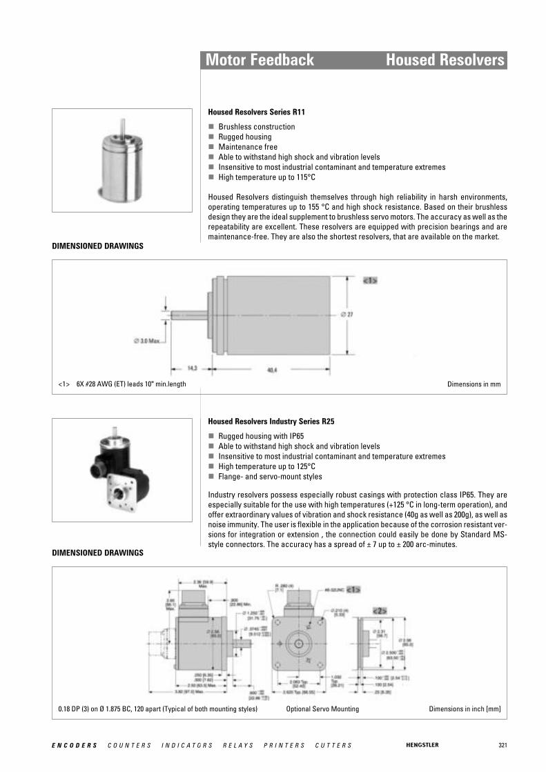
321E N C O D E R S C O U N T E R S I N D I C A T O R S R E L A Y S P R I N T E R S C U T T E R S
Housed Resolvers Industry Series R25
� Rugged housing with IP65� Able to withstand high shock and vibration levels� Insensitive to most industrial contaminant and temperature extremes� High temperature up to 125°C� Flange- and servo-mount styles
DIMENSIONED DRAWINGS
0.18 DP (3) on Ø 1.875 BC, 120 apart (Typical of both mounting styles) Optional Servo Mounting Dimensions in inch [mm]
Motor Feedback Housed Resolvers
Housed Resolvers Series R11
� Brushless construction� Rugged housing� Maintenance free� Able to withstand high shock and vibration levels� Insensitive to most industrial contaminant and temperature extremes� High temperature up to 115°C
Housed Resolvers distinguish themselves through high reliability in harsh environments,operating temperatures up to 155 °C and high shock resistance. Based on their brushlessdesign they are the ideal supplement to brushless servo motors. The accuracy as well as therepeatability are excellent. These resolvers are equipped with precision bearings and aremaintenance-free. They are also the shortest resolvers, that are available on the market.
DIMENSIONED DRAWINGS
<1> 6X #28 AWG (ET) leads 10" min.length Dimensions in mm
Industry resolvers possess especially robust casings with protection class IP65. They areespecially suitable for the use with high temperatures (+125 °C in long-term operation), andoffer extraordinary values of vibration and shock resistance (40g as well as 200g), as well asnoise immunity. The user is flexible in the application because of the corrosion resistant ver-sions for integration or extension , the connection could easily be done by Standard MS-style connectors. The accuracy has a spread of ± 7 up to ± 200 arc-minutes.

322 E N C O D E R S C O U N T E R S I N D I C A T O R S R E L A Y S P R I N T E R S C U T T E R S
Problem solutions from a single source.
Our wide range of accessory modules completes the encoder programme.
With these modules, we offer you an optimum means of meeting your application demands.
Accessories
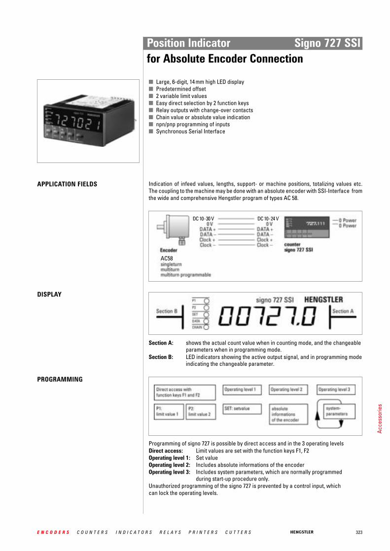
323E N C O D E R S C O U N T E R S I N D I C A T O R S R E L A Y S P R I N T E R S C U T T E R S
■ Large, 6-digit, 14 mm high LED display■ Predetermined offset■ 2 variable limit values■ Easy direct selection by 2 function keys■ Relay outputs with change-over contacts■ Chain value or absolute value indication■ npn/pnp programming of inputs■ Synchronous Serial Interface
Indication of infeed values, lengths, support- or machine positions, totalizing values etc.The coupling to the machine may be done with an absolute encoder with SSI-Interface fromthe wide and comprehensive Hengstler program of types AC 58.
APPLICATION FIELDS
DISPLAY
Section A: shows the actual count value when in counting mode, and the changeableparameters when in programming mode.
Section B: LED indicators showing the active output signal, and in programming modeindicating the changeable parameter.
PROGRAMMING
Programming of signo 727 is possible by direct access and in the 3 operating levelsDirect access: Limit values are set with the function keys F1, F2Operating level 1: Set valueOperating level 2: Includes absolute informations of the encoderOperating level 3: Includes system parameters, which are normally programmed
during start-up procedure only.Unauthorized programming of the signo 727 is prevented by a control input, whichcan lock the operating levels.
AC58
DC 10-30 V DC 10-24 V
Position Indicator Signo 727 SSIfor Absolute Encoder Connection
Acce
ssor
ies

324 E N C O D E R S C O U N T E R S I N D I C A T O R S R E L A Y S P R I N T E R S C U T T E R S
TECHNICAL DATA Display LED, indication value/preselection 6 digits, suppression ofleading zeros, programmable decimal point, minus sign
Digit Height 14 mmPower Supply Voltage Ub DC 12 ... 24 V or AC 115/230 V, depending on versionMax. current w/o load DC 12 ... 24 V < 250 mA,
AC 115/230 V < 60 mASensor Supply AC operation DC 12 ...24 V, DC operation UB - 2 V, Imax = 60 mAData Retention non-volatile memory > 10 yearsOperating Temperature 0 ... 50° CStorage Temperature -20 ... +70° CElectrical Connection plug-in terminalsMounting with clamping frameProtection Class (IEC 144) front side IP54, terminals IP20Noise Immunity EMC severity 3 according to IEC 801, part 2 + part 4Vibration resistance 10 m/s2 (10 ... 150 Hz) according to IEC 68-part 2-6Shock resistance 100 m/s2 (18 ms) according to IEC 68-part 2-27General design according to VDE 0411, DIN 57411, protection class IIInputs SSI Data +
SSI Data -Baud rate approx. 100 kHzControl Input Application Input 1, static
Display hold, Reset or Chain Reset(programmable)
Keylock staticOutputs SSI measure +
SSI measure -Relay 1 Out 1 and Out 2Contact Type changeover relaySwitching Voltage max. 250 VAC/30 VDC, mind 5 VAC/DCSwitching Current max. 1A, min. 10 mA
1 for versions with limit values only
Position Indicator Signo 727 SSIfor Absolute Encoder Connection

325E N C O D E R S C O U N T E R S I N D I C A T O R S R E L A Y S P R I N T E R S C U T T E R S
DIMENSIONAL DRAWINGS
CONNECTION PLAN
ORDERING DATA
opt. with interface RS 485, RS 232 on request
Please note:Absolute encoders with capped Gray Gode (e.g. 360 or 720) must not be connectedMax. encoder resolution: 12 Bit ST (singleturn) and
24 Bit MT (multiturn 12 + 12 Bit)
Type Absolute encoder Supply Ordering codeconnection
signo 727 without limit values SSI DC 12 - 24 V 0 727 111signo 727 without limit values SSI AC 115/230 V 0 727 112signo 727 with 2 limit values SSI DC 12 - 24 V 0 727 131signo 727 with 2 limit values SSI AC 115/230 V 0 727 132
1 L2 -3 -4 N
32 SENSOR: DC 12 - 24 V= /60mA31 0V30 DATA +29 DATA -28 CLOCK +27 CLOCK -26 KEYCLOCK PNP NPN25 APPL. 1 PNP NPN
} SSI !
230V
AC*3
2mAT
115V
AC*3
2mAT AC-POWER
SUPPLY50/60Hz
-L---N }
1 0V DC-POWER2 + DC 12 - 24V- Supply3 NC *0.25A F 0.16A T/IEC 1274 NC *0.25A T 0.20A T/UL 1985 NC6 OUT 17 DC 30 V-/1A 250VAC~/1A8 max. 250V9 NC10 OUT 211 DC 30 V -/1A250VAC~/1A12 max. 250V13 NC14 OUT 1 TR. DC-SUPPLY - 2V/10mA15 OUT 2 TR. DC-SUPPLY - 2V/10mA16 0V32 SENSOR: DC-SUPPLY - 2V/60mA31 0V30 DATA+29 DATA-28 CLOCK+27 CLOCK-26 KEYCLOCK PNP NPN26 APPL PNP NPN
}}
}ext. Fuse*
!} SSI
ext. Fuse*
version without limit values 115/220 VAC Version with limit values DC12/24 V
Position Indicator Signo 727 SSIfor Absolute Encoder Connection

326 E N C O D E R S C O U N T E R S I N D I C A T O R S R E L A Y S P R I N T E R S C U T T E R S
AC58-S/M/P WITHOPTIONAL SHOCK MODULE
Applications with vibration rates of up to >100 m/s2 and shock rates >1000 m/s2 require theuse of a shock module. By means of integrated attenuating elements, these encoder ratingsare reduced.
DIMENSIONAL DRAWINGENCODER WITH SHOCK MODULE,CONNECTING CABLE
DIMENSIONAL DRAWINGENCODER WITH SHOCK MODULE,FLANGE CONNECTOR
ORDERING DATA For the encoder option with shock module, please enquire by stating your desired encoder type.
(Accessories unit 1 540 239Flange ordering code: L.42 for RI 58, K.42 for AC 58)
Fixing flange by means of clamping flange or clamping eccentric, shaft by means of flexible coupling
Absolute max. shaft load axial 30 N, radial 100 NShaft diameter 10 mm
R for alternating bending -> 15 x cable diameterR for permanent bending -> 15 x cable diameter
Dimensions in mm
Dimensions in mm
Encoder with Shock Module
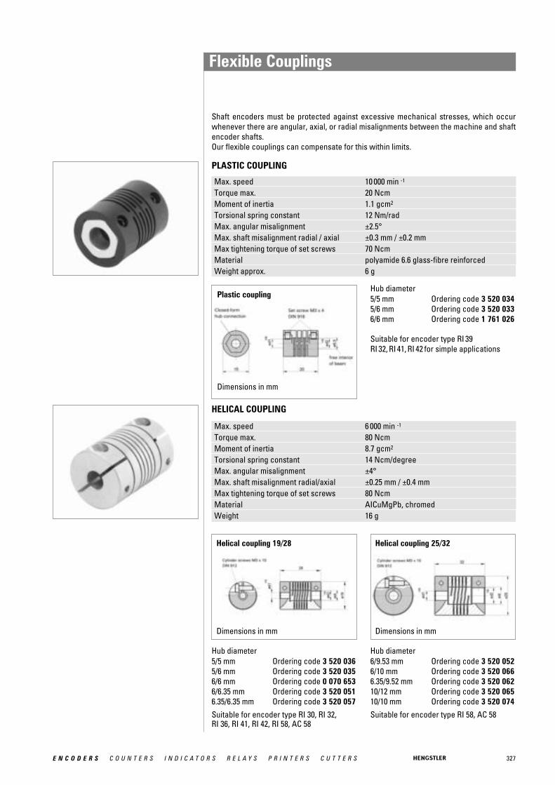
327E N C O D E R S C O U N T E R S I N D I C A T O R S R E L A Y S P R I N T E R S C U T T E R S
Helical coupling 25/32
Shaft encoders must be protected against excessive mechanical stresses, which occurwhenever there are angular, axial, or radial misalignments between the machine and shaftencoder shafts.Our flexible couplings can compensate for this within limits.
Hub diameter5/5 mm Ordering code 3 520 0365/6 mm Ordering code 3 520 0356/6 mm Ordering code 0 070 6536/6.35 mm Ordering code 3 520 0516.35/6.35 mm Ordering code 3 520 057
Suitable for encoder type RI 30, RI 32,RI 36, RI 41, RI 42, RI 58, AC 58
Max. speed 6 000 min -1
Torque max. 80 NcmMoment of inertia 8.7 gcm2
Torsional spring constant 14 Ncm/degreeMax. angular misalignment ±4°Max. shaft misalignment radial/axial ±0.25 mm / ±0.4 mmMax tightening torque of set screws 80 NcmMaterial AICuMgPb, chromedWeight 16 g
Hub diameter5/5 mm Ordering code 3 520 0345/6 mm Ordering code 3 520 0336/6 mm Ordering code 1 761 026
Suitable for encoder type RI 39RI 32, RI 41, RI 42 for simple applications
Max. speed 10 000 min -1
Torque max. 20 NcmMoment of inertia 1.1 gcm2
Torsional spring constant 12 Nm/radMax. angular misalignment ±2.5°Max. shaft misalignment radial / axial ±0.3 mm / ±0.2 mmMax tightening torque of set screws 70 NcmMaterial polyamide 6.6 glass-fibre reinforcedWeight approx. 6 g
Plastic coupling
Dimensions in mm
Helical coupling 19/28
PLASTIC COUPLING
HELICAL COUPLING
Hub diameter6/9.53 mm Ordering code 3 520 0526/10 mm Ordering code 3 520 0666.35/9.52 mm Ordering code 3 520 06210/12 mm Ordering code 3 520 06510/10 mm Ordering code 3 520 074
Suitable for encoder type RI 58, AC 58
Dimensions in mm Dimensions in mm
Flexible Couplings

328 E N C O D E R S C O U N T E R S I N D I C A T O R S R E L A Y S P R I N T E R S C U T T E R S
Isolited disk coupling
Dimensions in mm
Disk coupling
Dimensions in mm
ISOLATED DISK COUPLING
DISK COUPLING
DIMENSIONAL DRAWINGS
Max. speed 12 000 min -1
Torque max. 60 NcmMax. shaft misalignment radial ±0.3 mm
axial ±0.4 mmangular ±2.5°
Torsional spring constant 30 Nm/radMaterial Flanges aluminium, anodized
Spring disc plastic, glass-fibre reinforced
Hub diameter5/6 mm Ordering code 3 520 080 Suitable for encoder type RI 30, 6/6 mm Ordering code 3 520 081 RI 32, RI 36, RI 41, RI 42, RI 58, AC 586/10 mm Ordering code 3 520 0826/6.35 mm Ordering code 3 520 0836/9.53 mm Ordering code 3 520 0846.35/6.35 mm Ordering code 3 520 0857/7 mm Ordering code 3 520 08610/6.35 mm Ordering code 3 520 08710/10 mm Ordering code 3 520 088
Ordering code 0 070 663 suitable for encoder type RI 36, RI 58, AC 58
Max. speed 12 000 min -1
Torque max. 80 NcmMoment of inertia 19 gcm 2
Torsional spring constant 150 Nm/radMax. angular misalignment ±3.0°Max. shaft misalignment radial ±0.4 mm
axial ±0.4 mmMax tightening torque of set screws 80 NcmHub diameter d and d1 6 mm H 8Material coupling body, flange AICuMgPb, anodized
preloaded disc stainless steelWeight approx. 14.5 g
Flexible Couplings
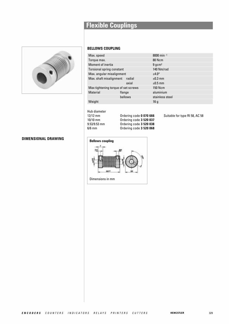
329E N C O D E R S C O U N T E R S I N D I C A T O R S R E L A Y S P R I N T E R S C U T T E R S
Bellows coupling
Dimensions in mm
BELLOWS COUPLING
DIMENSIONAL DRAWING
Hub diameter12/12 mm Ordering code 0 070 666 Suitable for type RI 58, AC 5810/10 mm Ordering code 3 520 0379.53/9.53 mm Ordering code 3 520 0386/6 mm Ordering code 3 520 068
Max. speed 8000 min -1
Torque max. 80 NcmMoment of inertia 9 gcm2
Torsional spring constant 140 Nm/radMax. angular misalignment ±4.0°Max. shaft misalignment radial ±0.3 mm
axial ±0.5 mmMax tightening torque of set screws 150 NcmMaterial flange aluminium
bellows stainless steelWeight 16 g
Flexible Couplings
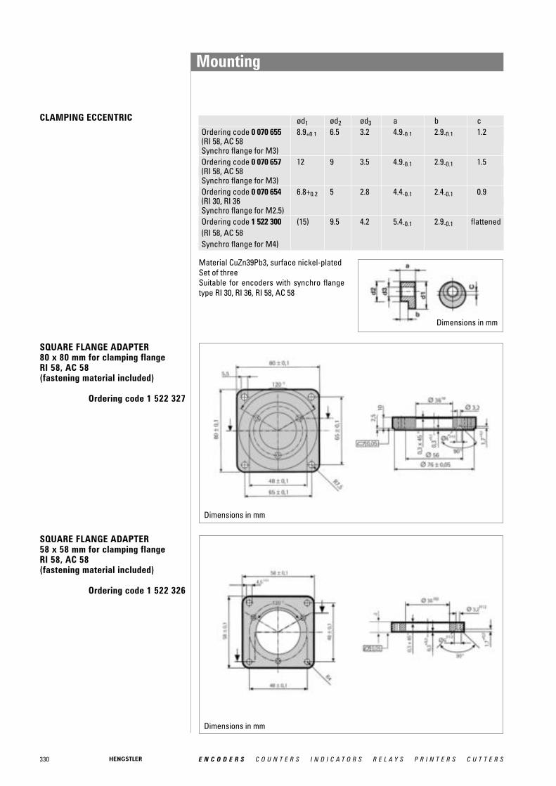
ød1 ød2 ød3 a b cOrdering code 0 070 655 8.9+0.1 6.5 3.2 4.9-0.1 2.9-0.1 1.2(RI 58, AC 58Synchro flange for M3)Ordering code 0 070 657 12 9 3.5 4.9-0.1 2.9-0.1 1.5(RI 58, AC 58Synchro flange for M3)Ordering code 0 070 654 6.8+0.2 5 2.8 4.4-0.1 2.4-0.1 0.9(RI 30, RI 36Synchro flange for M2.5)Ordering code 1 522 300 (15) 9.5 4.2 5.4-0.1 2.9-0.1 flattened(RI 58, AC 58Synchro flange for M4)
Dimensions in mm
330 E N C O D E R S C O U N T E R S I N D I C A T O R S R E L A Y S P R I N T E R S C U T T E R S
Material CuZn39Pb3, surface nickel-platedSet of threeSuitable for encoders with synchro flangetype RI 30, RI 36, RI 58, AC 58
SQUARE FLANGE ADAPTER 58 x 58 mm for clamping flange RI 58, AC 58 (fastening material included)
Ordering code 1 522 326
SQUARE FLANGE ADAPTER 80 x 80 mm for clamping flange RI 58, AC 58 (fastening material included)
Ordering code 1 522 327
Dimensions in mm
Dimensions in mm
CLAMPING ECCENTRIC
Mounting

331E N C O D E R S C O U N T E R S I N D I C A T O R S R E L A Y S P R I N T E R S C U T T E R S
SYNCHRO FLANGE ADAPTERfor clamping flange RI 58, AC 58(fastening material included)
Ordering code 1 522 328
SYNCHRO FLANGE ADAPTERfor clamping flange RI 58, same dimensions as TR HE 65(fastening material included)
Ordering code 1 522 542
SYNCHRO FLANGE ADAPTERfor clamping flange RI 58, same dimensions as AG 661(fastening material included)
Ordering code 1 522 547
Dimensions in mm
Dimensions in mm
Dimensions in mm
Mounting

332 E N C O D E R S C O U N T E R S I N D I C A T O R S R E L A Y S P R I N T E R S C U T T E R S
SYNCHRO FLANGE ADAPTERfor clamping flange RI 58, same dimensions as AG 100/110 (fastening material included)
Ordering code 1 522 548
FASTENING BRACKET (PLASTIC)for clamping flange RI 58, AC 58 (fastening material included)
Ordering code 1 522 329
FLANGE ADAPTERfor clamping flange AC 58,same dimensions as Gelma RAO 5(fastening material included)
Ordering code 1 540 336
Dimensions in mm
Dimensions in mm
Dimensions in mm
Mounting
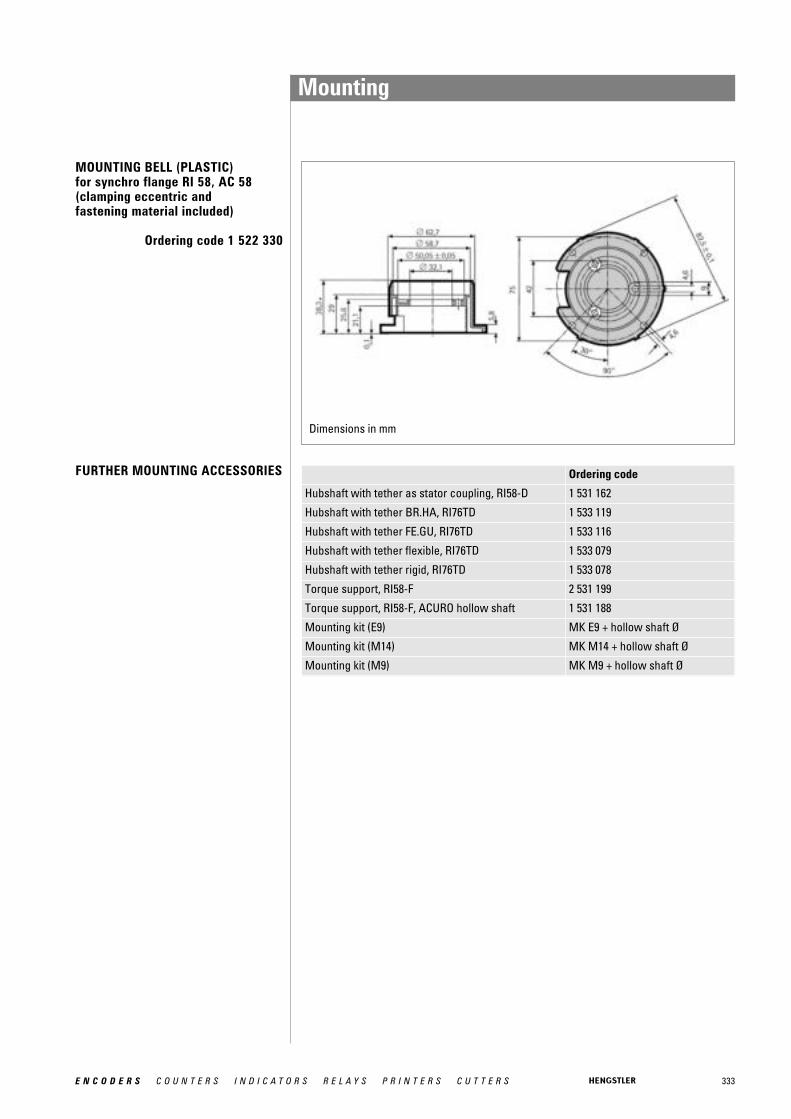
333E N C O D E R S C O U N T E R S I N D I C A T O R S R E L A Y S P R I N T E R S C U T T E R S
MOUNTING BELL (PLASTIC)for synchro flange RI 58, AC 58(clamping eccentric and fastening material included)
Ordering code 1 522 330
Dimensions in mm
Mounting
Ordering code
Hubshaft with tether as stator coupling, RI58-D 1 531 162
Hubshaft with tether BR.HA, RI76TD 1 533 119
Hubshaft with tether FE.GU, RI76TD 1 533 116
Hubshaft with tether flexible, RI76TD 1 533 079
Hubshaft with tether rigid, RI76TD 1 533 078
Torque support, RI58-F 2 531 199
Torque support, RI58-F, ACURO hollow shaft 1 531 188
Mounting kit (E9) MK E9 + hollow shaft Ø
Mounting kit (M14) MK M14 + hollow shaft Ø
Mounting kit (M9) MK M9 + hollow shaft Ø
FURTHER MOUNTING ACCESSORIES
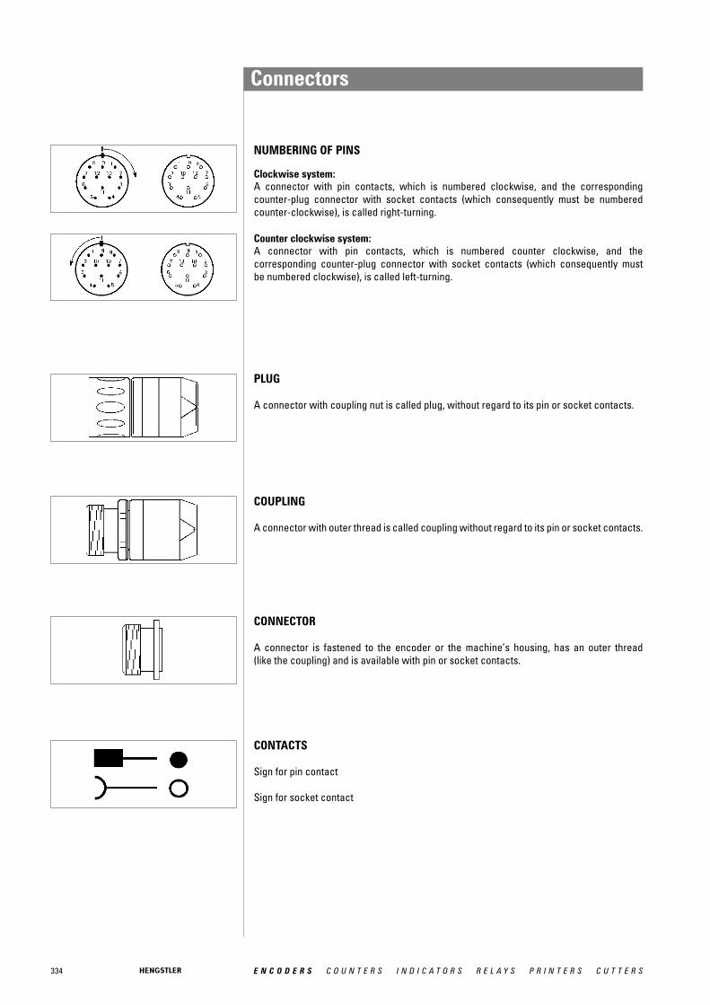
334 E N C O D E R S C O U N T E R S I N D I C A T O R S R E L A Y S P R I N T E R S C U T T E R S
NUMBERING OF PINS
Clockwise system:A connector with pin contacts, which is numbered clockwise, and the corresponding counter-plug connector with socket contacts (which consequently must be numberedcounter-clockwise), is called right-turning.
Counter clockwise system:A connector with pin contacts, which is numbered counter clockwise, and the corresponding counter-plug connector with socket contacts (which consequently must be numbered clockwise), is called left-turning.
PLUG
A connector with coupling nut is called plug, without regard to its pin or socket contacts.
COUPLING
A connector with outer thread is called coupling without regard to its pin or socket contacts.
CONNECTOR
A connector is fastened to the encoder or the machine’s housing, has an outer thread (like the coupling) and is available with pin or socket contacts.
CONTACTS
Sign for pin contact
Sign for socket contact
Connectors

335E N C O D E R S C O U N T E R S I N D I C A T O R S R E L A Y S P R I N T E R S C U T T E R S
2 VDW corresponding to Conin plastic-coated
CONNECTOR (PINS) FOR MOUNTING IN ENCODER HOUSING Ordering code
M23 (Conin), 12 pole, cw, mating connector for connection C/D (RI58, AC58)
3 539 198
M23 (Conin), 12 pole, ccw, identically equal to connection G/H (RI58, AC58)
3 539 230
CONNECTOR (SOCKET) MATCHING WITH ENCODER CONNECTOR 1 Ordering code
M12, 8 pole, mating connector for connection 7/8 (AC58 BiSS/SSI) 3 539 597
M16 (Binder), 6 pole, bent, IP40, mating connector for connection J/N(RI30, RI36, RI58)
3 539 209
M16 (Binder), 6 pole, gerade, IP67, mating connector for connectionJ/N (RI30, RI36, RI58)
3 539 472
M23 (Conin), 12 pole, PG9, ccw, mating connector for connection G/H (RI58, AC58)
3 539 229
M23 (Conin), 12 pole, PG9, cw, mating connector for connection C/D/-I (RI58, AC58)
3 539 202
M23 (Conin), 17 pole, PG9, ccw, mating connector for connection U/VSingleturn (AC58 Parallel, ST)
3 539 256
M23 (Conin), 17 pole, PG9, cw, mating connector for connection W/YSingleturn (AC58 Parallel, ST)
3 539 254
MS, 6 pole, mating connector for connection M/Q (RI58) 3 539 261
MS, 7 pole, mating connector for connection L/P (RI58) 3 539 262
MS, 10 pole, mating connector for connection K/O/R/T (RI58) 3 539 258
PT, 8 pole, mating connector for connection 1/2 (RI58) 3 539 333
COUPLING (SOCKET) MATCHING WITH ENCODER CABLE WITH CONNECTOR
Ordering code
M23 (Conin), 12 pole, cw, mating connector for connection -C (cable plug 3 539 186) (RI30, RI36, RI58, RI76, RI80, AC58 Interbus)
3 539 187
M23 (VDW 2), 12 pole, cw, mating connector for connection -B (cable plug 3 539 252) (RI30, RI36, RI58, RI76, RI80)
3 539 304
SUB-D, 37 pole, mating connector for connection -F (cable plug 1 542 045)(AC 58 Parallel MT)
1 542 024
CONNECTOR (SOCKET) MATCHING WITH ENCODER CABLE WITH CONNECTOR
Ordering code
M23 (Conin), 12 pole, ccw, mating connector for connection G/H/-D/-H(RI30, RI36, RI58, RI76, RI80)
3 539 229
M23 (VDW 2), 12 pole, ccw, mating connector for connection -E (cable plug 3 539 274) (RI30, RI36, RI58, RI76, RI80)
3 539 305
Connectors
1 Extension cables with plug refer to “Connecting cables”

336 E N C O D E R S C O U N T E R S I N D I C A T O R S R E L A Y S P R I N T E R S C U T T E R S
Connectors
CONNECTOR (PINS) ON CONNECTING CABLE SUITABLE FOR DOWNSTREAM LOGIC CIRCUIT
Ordering code
M23 (Conin), 12 pole, PG9, ccw (RI30, RI36, RI58, RI76, RI80) 3 539 316
M23 (Conin), 12 pole, PG9, cw (RI30, RI36, RI58, RI76, RI80) 3 539 186
M23 (Conin), 17 pole, PG9, ccw (AC58 Parallel MT) 3 539 309
M23 (Conin), 17 pole, PG9, cw (AC58 Parallel MT) 3 539 317
M23 (VDW 1), 12 pole, PG9, cw (RI30, RI36, RI58, RI76, RI80) 3 539 252
COUPLING (PINS) ON CONNECTING CABLE SUITABLE FOR DOWNSTREAM LOGIC CIRCUIT
Ordering code
M23 (Conin), 12 pole, PG9, ccw (RI30, RI36, RI58, RI76, RI80) 3 539 273
M23 (Conin), 12 pole, PG9, cw (RI30, RI36, RI58, RI76, RI80) 3 539 301
M23 (Conin), 17 pole, PG9, ccw (AC58 Parallel MT) 3 539 303
M23 (Conin), 17 pole, PG9, cw (AC58 Parallel MT) 3 539 302
M23 (VDW 1), 12 pole, PG9, ccw (RI30, RI36, RI58, RI76, RI80) 3 539 274
CONNECTOR (SOCKET) FOR MOUNTING INTO DOWNSTREAM LOGIC CIRCUIT HOUSING
Ordering code
M23 (Conin), 12 pole, ccw (RI30, RI36, RI58, RI76, RI80, AC58 BiSS/SSI,AC58 CANopen, AC58 CANlayer2, AC58 SSI-P)
3 539 319
M23 (Conin), 12 pole, cw (RI30, RI36, RI58, RI76, RI80, AC58 BiSS/SSI,AC58 CANopen, AC58 CANlayer2, AC58 SSI-P)
3 539 318
Mounting accessories Ordering code
Mounting spanner for CONIN connectors 3 539 343
CONNECTOR FOR CONNECTING BUS COVER WITH 2X M23 Ordering code
M23 (Conin), 12 pole, PG9, cw, pins (AC 58 Profibus) 3 539 186
M23 (Conin), 12 pole, PG9, cw, socket (AC 58 Profibus) 3 539 202
M23 (Conin), 9 pole, PG9, cw, pins(AC58 CANopen, AC58 CANlayer2, AC58 Interbus)
3 539 293
M23 (Conin), 9 pole, PG9, cw, socket, (AC58 CANopen, AC58 CANlayer2, AC58 Interbus)
3 539 294
1 VDW corresponding to Conin plastic-coated
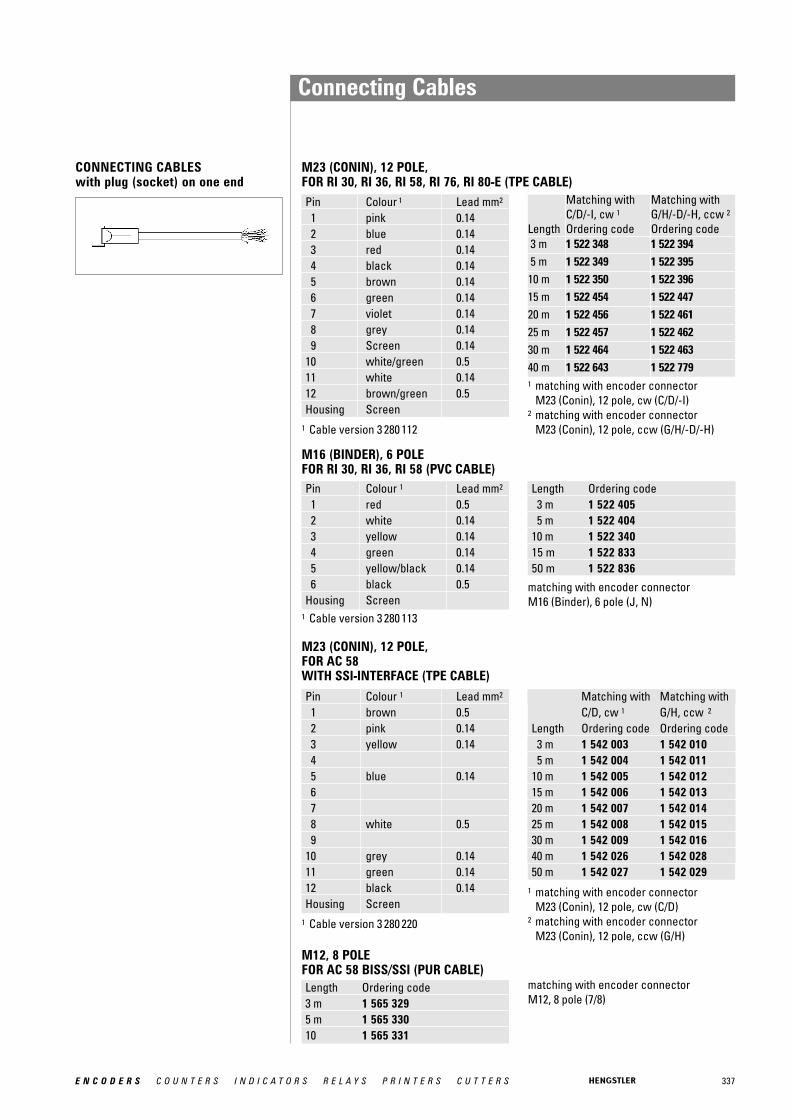
337E N C O D E R S C O U N T E R S I N D I C A T O R S R E L A Y S P R I N T E R S C U T T E R S
CONNECTING CABLESwith plug (socket) on one end
Pin Colour 1 Lead mm2
1 pink 0.142 blue 0.143 red 0.144 black 0.145 brown 0.146 green 0.147 violet 0.148 grey 0.149 Screen 0.14
10 white/green 0.511 white 0.1412 brown/green 0.5Housing Screen
Pin Colour 1 Lead mm2
1 red 0.52 white 0.143 yellow 0.144 green 0.145 yellow/black 0.146 black 0.5
Housing Screen
Length Ordering code3 m 1 522 4055 m 1 522 404
10 m 1 522 34015 m 1 522 83350 m 1 522 836
Pin Colour 1 Lead mm2
1 brown 0.52 pink 0.143 yellow 0.1445 blue 0.14678 white 0.59
10 grey 0.1411 green 0.1412 black 0.14Housing Screen
Matching with Matching with C/D, cw 1 G/H, ccw 2
Length Ordering code Ordering code3 m 1 542 003 1 542 0105 m 1 542 004 1 542 011
10 m 1 542 005 1 542 01215 m 1 542 006 1 542 01320 m 1 542 007 1 542 01425 m 1 542 008 1 542 01530 m 1 542 009 1 542 01640 m 1 542 026 1 542 02850 m 1 542 027 1 542 029
M23 (CONIN), 12 POLE, FOR RI 30, RI 36, RI 58, RI 76, RI 80-E (TPE CABLE)
M16 (BINDER), 6 POLEFOR RI 30, RI 36, RI 58 (PVC CABLE)
M23 (CONIN), 12 POLE, FOR AC 58WITH SSI-INTERFACE (TPE CABLE)
1 Cable version 3 280 112
1 Cable version 3 280 113
1 Cable version 3 280 220
matching with encoder connectorM16 (Binder), 6 pole (J, N)
1 matching with encoder connector M23 (Conin), 12 pole, cw (C/D)
2 matching with encoder connector M23 (Conin), 12 pole, ccw (G/H)
Length Ordering code3 m 1 565 3295 m 1 565 33010 1 565 331
M12, 8 POLEFOR AC 58 BISS/SSI (PUR CABLE)
Connecting Cables
Length
Matching withC/D/-I, cw 1Ordering code
Matching withG/H/-D/-H, ccw 2Ordering code
3 m 1 522 348 1 522 3945 m 1 522 349 1 522 395
10 m 1 522 350 1 522 39615 m 1 522 454 1 522 44720 m 1 522 456 1 522 46125 m 1 522 457 1 522 46230 m 1 522 464 1 522 46340 m 1 522 643 1 522 7791 matching with encoder connector
M23 (Conin), 12 pole, cw (C/D/-I)2 matching with encoder connector
M23 (Conin), 12 pole, ccw (G/H/-D/-H)
matching with encoder connector M12, 8 pole (7/8)

338 E N C O D E R S C O U N T E R S I N D I C A T O R S R E L A Y S P R I N T E R S C U T T E R S
Colour 1 Pin Colour 1 Pinwhite/green 6 pink/green 18brown/green 25 yellow/pink 10white/yellow 7 green/blue 30yellow/brown 26 yellow/blue 12white/grey 8 red 13grey/brown 27 white 31white/pink 9 blue 1pink/brown 28 black 20
M23 (CONIN), 12 POLEFOR AC 58 SSI-P (TPE CABLE)Pin Colour 1 Lead mm2
1 green 0.142 yellow 0.143 pink 0.144 grey 0.145 brown 0.146 white 0.147 black 0.148 blue 0.149 red 0.14
10 violet 0.1411 white 0.512 brown 0.5Housing Screen
ccw 1
Length Ordering code3 m 1 543 0025 m 1 543 003
10 m 1 543 00415 m 1 543 00520 m 1 543 00625 m 1 543 00730 m 1 543 00840 m 1 543 01550 m 1 543 016
Length Ordering code1 m 1 542 1633 m 1 542 0205 m 1 542 021
10 m 1 542 02215 m 1 542 172
Length Ordering code20 m 1 542 17325 m 1 542 17430 m 1 542 17540 m 1 542 17650 m 1 542 177
SUB-D 37 POLE FOR AC 58 PARALLEL Multiturn(TPE CABLE)
MS, 10 POLE FOR RI 58 (TPE CABLE)
Pin Colour 1 Lead mm2
A brown 0.14B grey 0.14C red 0.14D brown/green 0.5E violet 0.14F white/green 0.5G green 0.14H pink 0.14I black 0.14J Screen 0.14
Length Ordering code3 m 1 522 6105 m 1 522 754
Colour 1 Pin Colour 1 Pinbrown 2 white/blue 14green 21 brown/blue 33yellow 3 white/red 15grey 22 brown/red 34pink 4 white/black 16violet 23 brown/black 35grey/pink 5 grey/green 17red/blue 24 yellow/grey 36
1 Cable version 3 280 112
1 Cable version 3 280 220
1 Cable version 3 280 221
1 matching with encoder connector M23 (Conin), 12 pole, ccw (G/H)
CONNECTING CABLESwith plug (socket) on one end
Connecting Cables
matching with encoder connector MS, 10 pole (O/K)
matching with encoder connector SUB-D, 37 pole (cable plug -F)
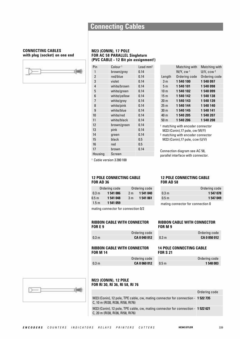
339E N C O D E R S C O U N T E R S I N D I C A T O R S R E L A Y S P R I N T E R S C U T T E R S
M23 (CONIN), 17 POLE FOR AC 58 PARALLEL Singleturn(PVC CABLE - 12 Bit pin assignment!)
Pin Colour 1 Lead mm2
1 brown/grey 0.142 red/blue 0.143 violet 0.144 white/brown 0.145 white/green 0.146 white/yellow 0.147 white/grey 0.148 white/pink 0.149 white/blue 0.14
10 white/red 0.1411 white/black 0.1412 brown/green 0.1413 pink 0.1414 green 0.1415 black 0.516 red 0.517 brown 0.14Housing Screen
Matching with Matching withW/Y, cw 1 U/V, ccw 2
Length Ordering code Ordering code3 m 1 540 100 1 540 0975 m 1 540 101 1 540 098
10 m 1 540 102 1 540 09915 m 1 540 142 1 540 13820 m 1 540 143 1 540 139 25 m 1 540 144 1 540 14030 m 1 540 145 1 540 14140 m 1 540 205 1 540 20750 m 1 540 206 1 540 208
1 Cable version 3 280 100
1 matching with encoder connector M23 (Conin),17 pole, cw (W/Y)
2 matching with encoder connector M23 (Conin),17 pole, ccw (U/V)
Connection diagram see AC 58,parallel interface with connector.
Connecting Cables
CONNECTING CABLESwith plug (socket) on one end
mating connector for connection 0/2
14 POLE CONNECTING CABLE FOR S 21
Ordering code0.5 m 1 548 003
12 POLE CONNECTING CABLE FOR AD 36
Ordering code Ordering code0.3 m 1 541 006 2 m 1 541 040
0.5 m 1 541 048 3 m 1 541 0611.5 m 1 541 059
12 POLE CONNECTING CABLE FOR AD 58
Ordering code0.3 m 1 547 0780.5 m 1 547 049
mating connector for connection 0
RIBBON CABLE WITH CONNECTORFOR E 9
Ordering code0.3 m CA 0 040 012
RIBBON CABLE WITH CONNECTORFOR M 9
Ordering code0.3 m CA 0 050 012
RIBBON CABLE WITH CONNECTORFOR M 14
Ordering code0.3 m CA 0 060 012
Ordering code
M23 (Conin), 12 pole, TPE cable, cw, mating connector for connection -C, 10 m (RI30, RI36, RI58, RI76)
1 522 735
M23 (Conin), 12 pole, TPE cable, cw, mating connector for connection -C, 20 m (RI30, RI36, RI58, RI76)
1 522 621
M23 (CONIN), 12 POLE FOR RI 30, RI 36, RI 58, RI 76

340 E N C O D E R S C O U N T E R S I N D I C A T O R S R E L A Y S P R I N T E R S C U T T E R S
Connecting Cables
CONNECTING CABLES with connector on both ends
cwLength1 Ordering code3 m 1 542 0175 m 1 542 018
10 m 1 542 019
Ordering codeTPE cable for RI 3 280 112 + length(12-core + screen)PVC cable for RI 3 280 114 + length(10-core + screen)PVC cable for RI 3 280 113 + length(6-core + screen)PVC cable for AC58 Parallel ST 3 280 100 + length(20-core + screen)TPE cable for AC58 SSI, AC58 Interbus 3 280 220 + length(12-core + screen)TPE cable for AC58 Parallel MT 3 280 221 + length(32-core + screen)
CABLE NOT MADE UPWITH CONNECTORS
M23 (CONIN), 12 POLE FOR AC58 INTERBUS (TPE CABLE)
1 Cable version 3 280 220
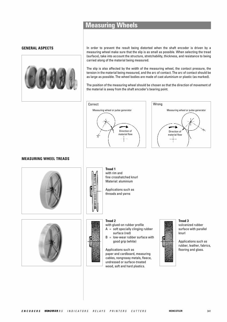
341E N C O D E R S C O U N T E R S I N D I C A T O R S R E L A Y S P R I N T E R S C U T T E R S
GENERAL ASPECTS In order to prevent the result being distorted when the shaft encoder is driven by a measuring wheel make sure that the slip is as small as possible. When selecting the tread(surface), take into account the structure, stretchability, thickness, and resistance to beingcarried along of the material being measured.
The slip is also affected by the width of the measuring wheel, the contact pressure, the tension in the material being measured, and the arc of contact. The arc of contact should beas large as possible. The wheel bodies are made of cast aluminium or plastic (as marked).
The position of the measuring wheel should be chosen so that the direction of movement of the material is away from the shaft encoder’s bearing point.
Correct Wrong
Measuring wheel or pulse generator
Direction ofmaterial flow
Measuring wheel or pulse generator
Direction ofmaterial flow
MEASURING WHEEL TREADS
Tread 1with rim and fine crosshatched knurlMaterial: aluminium
Applications such as threads and yarns
Tread 3vulcanized rubbersurface with parallelknurl
Applications such as rubber, leather, fabrics,flooring and glass.
Tread 2with glued-on rubber profileA = soft specially clinging rubber
surface (red)B = low-wear rubber surface with
good grip (white)
Applications such aspaper and cardboard, measuring cables, nongreasy metals, fleece, undressed or surface-treated wood, soft and hard plastics.
Measuring Wheels

342 E N C O D E R S C O U N T E R S I N D I C A T O R S R E L A Y S P R I N T E R S C U T T E R S
Tread 4aluminium withparallel knurl
Applications such asrubber, soft plastics, wood with rough surface, and to a limited extent for fabrics.
ORDERING DATAAluminium
Plastic
Tread 7carding belt
Applications such ascarpets and coarse fabrics.
Tread 6plastic surface
Applications such as wire, greasy metals, and steel sections.
Tread 5with rim, aluminium with parallel knurl
Applications such as threads, yarns, and bands.
1 PTB approved
Other measuring wheels available on request
Dia-meter
Circ-umfe-rence Tread
Width ofbearingsurface
Bore diameter (mm) fitting to encoder shaft4.0 mm 6.0 mm 7.0 mm 10.0 mm 12.0 mm
6.37 cm 0.2 m 1 4 mm 0 601 014 0 601 015 0 601 0172 A 12 mm 0 601 0182 B 12 mm 0 601 118 0 601 048 0 601 0492 A 24 mm 0 601 020 0 601 0922 B 24 mm 0 601 1924 20.5 mm 0 601 0234 20 mm 0 601 0935 16.5 mm 0 601 026 0 601 094
15.92 cm 0.5 m 2 A 25 mm 0 601 0502 B 25 mm 0 601 150 0 601 1512 B 25 mm 0 601 2043 25 mm 0 601 059 0 601 156 0 601 1594 25 mm 0 601 121 1 0 601 1576 25 mm 0 601 063 1 0 601 163 0 601 165
5.73 cm 1/5 yd. 1 4 mm 0 601 034 0 601 0372 A 24 mm 0 601 0425 16.5 mm 0 601 096
14.33 cm 1/2 yd. 4 25 mm 0 601 0619.70 cm 1 foot 2 A 25 mm 0 601 071
2 B 25 mm 0 601 171
6.37 cm 0.2 m 1 4 mm 0 601 1004 25 mm 0 601 301
15.92 cm 0.5 m 6 25 mm 0 601 300
Measuring Wheels
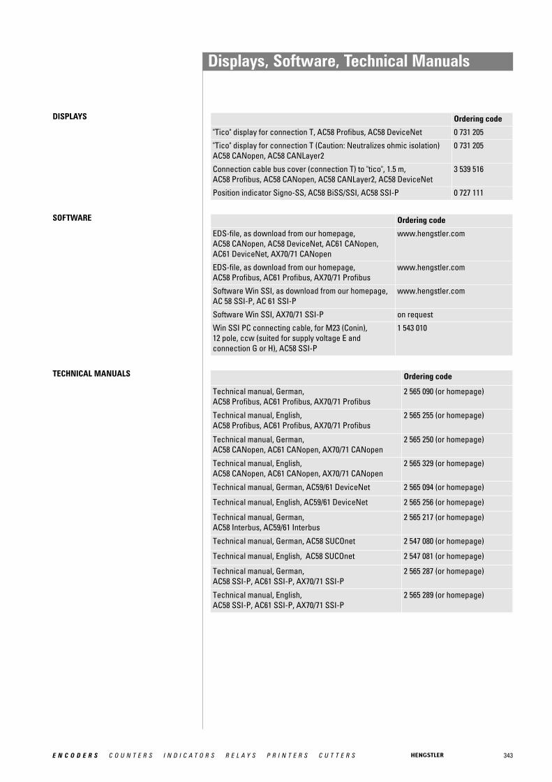
343E N C O D E R S C O U N T E R S I N D I C A T O R S R E L A Y S P R I N T E R S C U T T E R S
Displays, Software, Technical Manuals
DISPLAYS Ordering code
"Tico" display for connection T, AC58 Profibus, AC58 DeviceNet 0 731 205
"Tico" display for connection T (Caution: Neutralizes ohmic isolation)AC58 CANopen, AC58 CANLayer2
0 731 205
Connection cable bus cover (connection T) to "tico", 1.5 m, AC58 Profibus, AC58 CANopen, AC58 CANLayer2, AC58 DeviceNet
3 539 516
Position indicator Signo-SS, AC58 BiSS/SSI, AC58 SSI-P 0 727 111
TECHNICAL MANUALS
SOFTWARE Ordering code
EDS-file, as download from our homepage, AC58 CANopen, AC58 DeviceNet, AC61 CANopen,AC61 DeviceNet, AX70/71 CANopen
www.hengstler.com
EDS-file, as download from our homepage,AC58 Profibus, AC61 Profibus, AX70/71 Profibus
www.hengstler.com
Software Win SSI, as download from our homepage,AC 58 SSI-P, AC 61 SSI-P
www.hengstler.com
Software Win SSI, AX70/71 SSI-P on request
Win SSI PC connecting cable, for M23 (Conin), 12 pole, ccw (suited for supply voltage E and connection G or H), AC58 SSI-P
1 543 010
Ordering code
Technical manual, German,AC58 Profibus, AC61 Profibus, AX70/71 Profibus
2 565 090 (or homepage)
Technical manual, English,AC58 Profibus, AC61 Profibus, AX70/71 Profibus
2 565 255 (or homepage)
Technical manual, German, AC58 CANopen, AC61 CANopen, AX70/71 CANopen
2 565 250 (or homepage)
Technical manual, English,AC58 CANopen, AC61 CANopen, AX70/71 CANopen
2 565 329 (or homepage)
Technical manual, German, AC59/61 DeviceNet 2 565 094 (or homepage)
Technical manual, English, AC59/61 DeviceNet 2 565 256 (or homepage)
Technical manual, German,AC58 Interbus, AC59/61 Interbus
2 565 217 (or homepage)
Technical manual, German, AC58 SUCOnet 2 547 080 (or homepage)
Technical manual, English, AC58 SUCOnet 2 547 081 (or homepage)
Technical manual, German, AC58 SSI-P, AC61 SSI-P, AX70/71 SSI-P
2 565 287 (or homepage)
Technical manual, English, AC58 SSI-P, AC61 SSI-P, AX70/71 SSI-P
2 565 289 (or homepage)
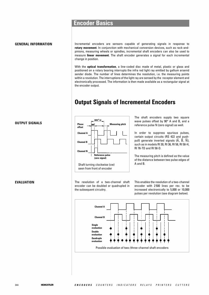
344 E N C O D E R S C O U N T E R S I N D I C A T O R S R E L A Y S P R I N T E R S C U T T E R S
Incremental encoders are sensors capable of generating signals in response to rotary movement. In conjunction with mechanical conversion devices, such as rack-and-pinions, measuring wheels or spindles, incremental shaft encoders can also be used tomeasure linear movement. The shaft encoder generates a signal for each incrementalchange in position.
With the optical transformation, a line-coded disc made of metal, plastic or glass and positioned on a rotary bearing interrupts the infra red light ray emitted by gallium arsenid sender diode. The number of lines determines the resolution, i.e. the measuring points within a revolution. The interruptions of the light ray are sensed by the receptor element andelectronically processed. The information is then made available as a rectangular signal atthe encoder output.
Phaseoffset
Channel A
Channel B
Channel N
Reference pulse(zero signal)
Shaft turning clockwise (cw)seen from front of encoder
Possible evaluation of two-/three-channel shaft encoders
Measuring pitch
The resolution of a two-channel shaft encoder can be doubled or quadrupled inthe subsequent circuitry.
EVALUATION
OUTPUT SIGNALS
The shaft encoders supply two squarewave pulses offset by 90° A and B, and areference pulse N (zero signal) as well.
In order to suppress spurious pulses, certain output circuits (RS 422 and push-pull) generate inverted signals ( , , ),such as in models RI 30, RI 36, RI 58, RI 58-H,RI 76-TD and RI 58-D.
The measuring pitch is defined as the valueof the distance between two pulse edges ofA and B.
NBA
Output Signals of Incremental Encoders
This enables the resolution of a two-channelencoder with 2 500 lines per rev. to beincreased electronically to 5,000 or 10,000pulses per revolution (see diagram below).
GENERAL INFORMATION
Channel A
Channel B
Single evaluation
Double evaluation
Quadrupleevaluation
Encoder Basics

345E N C O D E R S C O U N T E R S I N D I C A T O R S R E L A Y S P R I N T E R S C U T T E R S
All encoders of the industrial types RI 30, RI 36, RI 58, RI 58-H, RI 58-D, RA 70-I as wellas the absolute encoders ACURO, complywith protection class IP65 according to EN60529 and IEC 529, unless otherwise stated.
These specifications are valid for the housing and the cable output and also forplugged in socket connectors. The shaftinput complies with protection class IP64. Ifhowever the encoder is mounted vertically,there must be no standing water present atthe shaft input and the ball bearings.
Maximum permissible speed as a function of number of pulses and signal frequency of shaft encoder
PROTECTION CLASS
SPEED The maximum permissible speed of a shaftencoder is derived from:
• the mechanically permissible r.p.m,• the minimum permissible pulse-edge
spacing of the square-wave output signals of the shaft encoder for the subsequent circuitry, which depends on the tolerance of the phase offset,
• the functional speed, which is limited bythe pulse frequency.
The mechanically permissible r.p.m. is specified for each shaft encoder among the mechanical characteristics.
In general, the control circuitry does notpermit less than a certain minimum edgespacing between the square-wave outputsignal pulses. The minimum pulse-edgespacing is specified for each model of shaft encoder among the electrical characteristics.
The functional speed of an encoder is obtai-ned by the equation:
n max = fmax · 103 · 60 / Z
nmax = maximum functional speed [r.p.m.]f max = maximum pulse frequency of
shaft encoder, or input frequency of downstream circuitry [kHz]
z = number of pulses of shaft encoder
In case the standard protection class IP64is not sufficient for the shaft input, e.g. with vertical mounting of the encoder, theencoders must be protected by additionallabyrinth or pot-type seals.
On request our encoders are also availablewith protection class IP67 for the shaft inputand for the housing.
RPM
Numberof pulses
Encoder BasicsMaximum Speed,Protection Class
Tech
nica
l Ba
sics
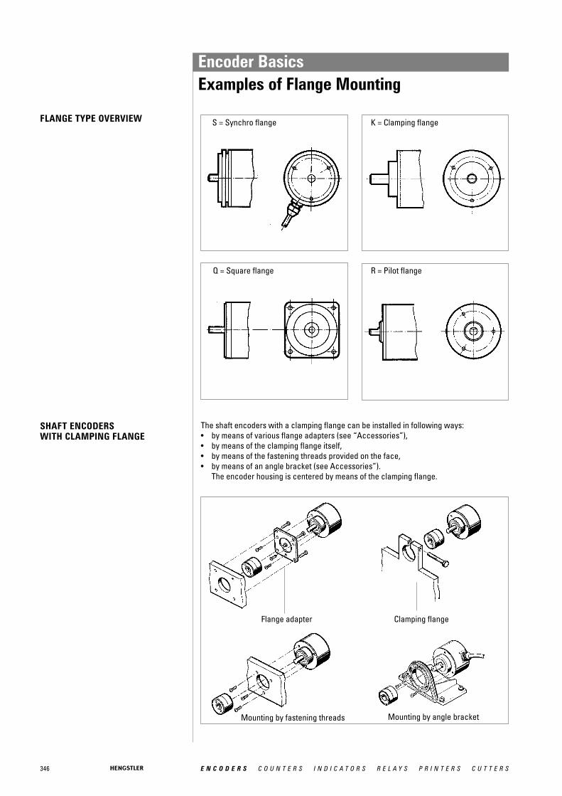
346 E N C O D E R S C O U N T E R S I N D I C A T O R S R E L A Y S P R I N T E R S C U T T E R S
S = Synchro flange
Q = Square flange
Flange adapter Clamping flange
Mounting by fastening threads Mounting by angle bracket
FLANGE TYPE OVERVIEW
SHAFT ENCODERSWITH CLAMPING FLANGE
The shaft encoders with a clamping flange can be installed in following ways:• by means of various flange adapters (see “Accessories”),• by means of the clamping flange itself,• by means of the fastening threads provided on the face,• by means of an angle bracket (see Accessories”).
The encoder housing is centered by means of the clamping flange.
K = Clamping flange
R = Pilot flange
Encoder BasicsExamples of Flange Mounting
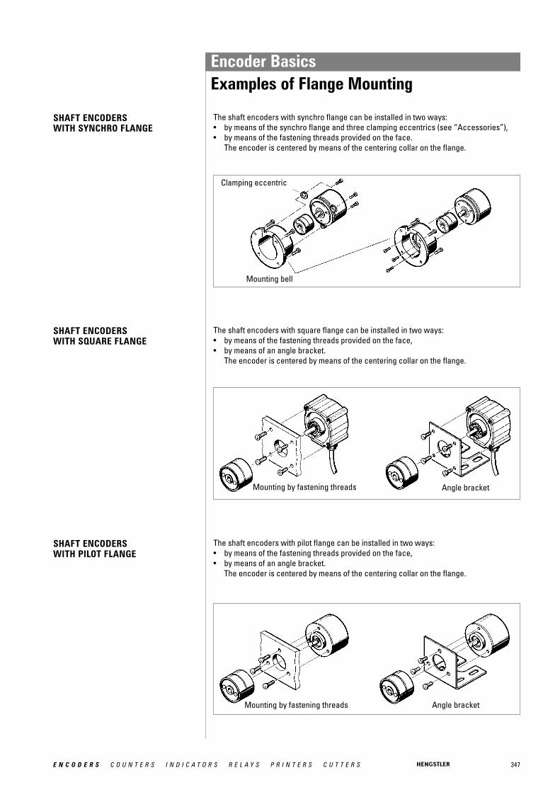
347E N C O D E R S C O U N T E R S I N D I C A T O R S R E L A Y S P R I N T E R S C U T T E R S
Mounting bell
Clamping eccentric
Angle bracketMounting by fastening threads
Mounting by fastening threads Angle bracket
SHAFT ENCODERS WITH PILOT FLANGE
SHAFT ENCODERS WITH SQUARE FLANGE
The shaft encoders with pilot flange can be installed in two ways:• by means of the fastening threads provided on the face,• by means of an angle bracket.
The encoder is centered by means of the centering collar on the flange.
The shaft encoders with square flange can be installed in two ways:• by means of the fastening threads provided on the face,• by means of an angle bracket.
The encoder is centered by means of the centering collar on the flange.
SHAFT ENCODERS WITH SYNCHRO FLANGE
The shaft encoders with synchro flange can be installed in two ways:• by means of the synchro flange and three clamping eccentrics (see “Accessories”),• by means of the fastening threads provided on the face.
The encoder is centered by means of the centering collar on the flange.
Encoder BasicsExamples of Flange Mounting
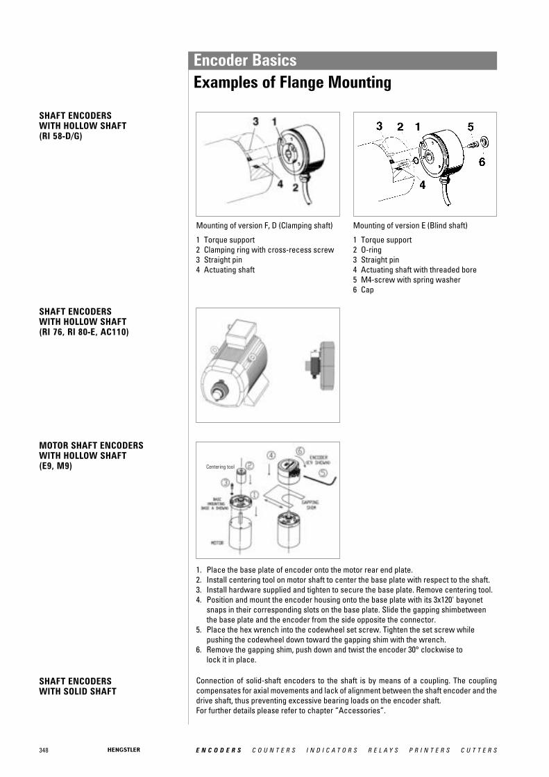
348 E N C O D E R S C O U N T E R S I N D I C A T O R S R E L A Y S P R I N T E R S C U T T E R S
SHAFT ENCODERS WITH HOLLOW SHAFT(RI 76, RI 80-E, AC110)
MOTOR SHAFT ENCODERSWITH HOLLOW SHAFT(E9, M9)
SHAFT ENCODERSWITH SOLID SHAFT
Connection of solid-shaft encoders to the shaft is by means of a coupling. The couplingcompensates for axial movements and lack of alignment between the shaft encoder and thedrive shaft, thus preventing excessive bearing loads on the encoder shaft.For further details please refer to chapter “Accessories”.
SHAFT ENCODERS WITH HOLLOW SHAFT(RI 58-D/G)
Mounting of version F, D (Clamping shaft)
1 Torque support2 Clamping ring with cross-recess screw3 Straight pin4 Actuating shaft
Mounting of version E (Blind shaft)
1 Torque support2 O-ring3 Straight pin4 Actuating shaft with threaded bore5 M4-screw with spring washer6 Cap
1. Place the base plate of encoder onto the motor rear end plate.2. Install centering tool on motor shaft to center the base plate with respect to the shaft.3. Install hardware supplied and tighten to secure the base plate. Remove centering tool.4. Position and mount the encoder housing onto the base plate with its 3x120' bayonet
snaps in their corresponding slots on the base plate. Slide the gapping shimbetween the base plate and the encoder from the side opposite the connector.
5. Place the hex wrench into the codewheel set screw. Tighten the set screw while pushing the codewheel down toward the gapping shim with the wrench.
6. Remove the gapping shim, push down and twist the encoder 30° clockwise tolock it in place.
Centering tool
Encoder BasicsExamples of Flange Mounting
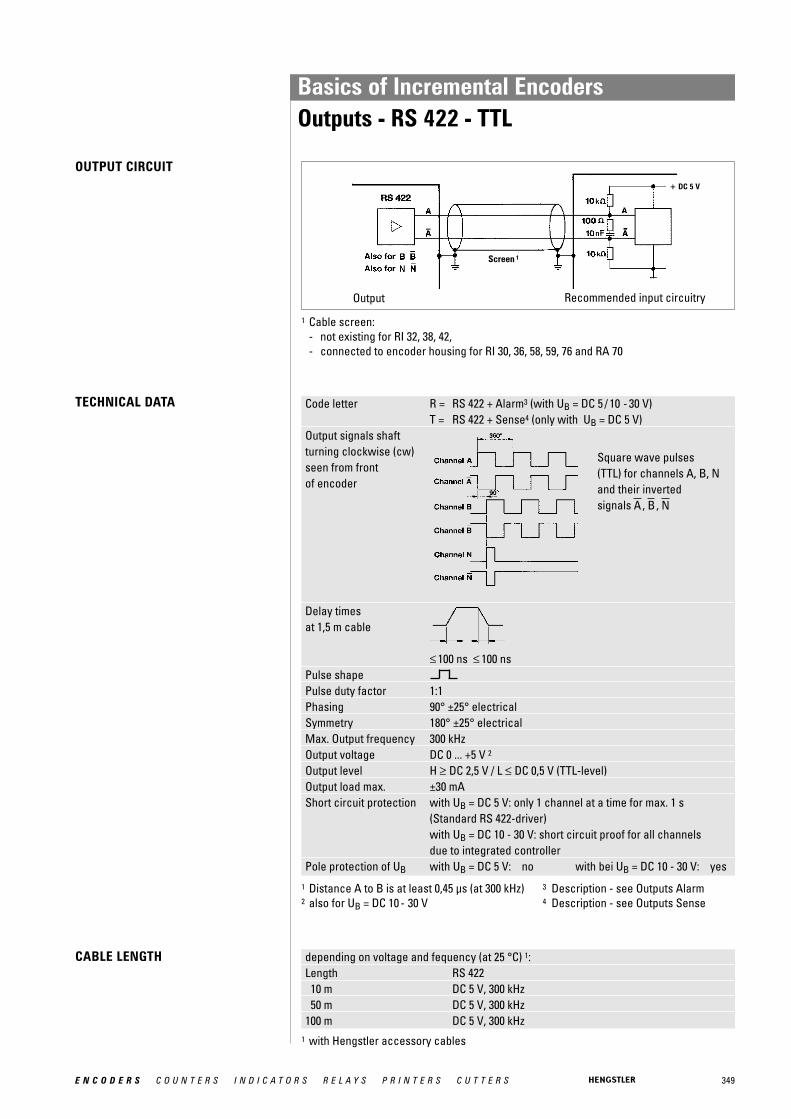
349E N C O D E R S C O U N T E R S I N D I C A T O R S R E L A Y S P R I N T E R S C U T T E R S
Code letter R = RS 422 + Alarm3 (with UB = DC 5 / 10 - 30 V)T = RS 422 + Sense4 (only with UB = DC 5 V)
Output signals shaft turning clockwise (cw)seen from frontof encoder
Delay times at 1,5 m cable
≤ 100 ns ≤ 100 nsPulse shapePulse duty factor 1:1Phasing 90° ±25° electricalSymmetry 180° ±25° electricalMax. Output frequency 300 kHzOutput voltage DC 0 ... +5 V 2
Output level H ≥ DC 2,5 V / L ≤ DC 0,5 V (TTL-level)Output load max. ±30 mAShort circuit protection with UB = DC 5 V: only 1 channel at a time for max. 1 s
(Standard RS 422-driver)with UB = DC 10 - 30 V: short circuit proof for all channels due to integrated controller
Pole protection of UB with UB = DC 5 V: no with bei UB = DC 10 - 30 V: yes
TECHNICAL DATA
CABLE LENGTH depending on voltage and fequency (at 25 °C) 1:Length RS 42210 m DC 5 V, 300 kHz50 m DC 5 V, 300 kHz
100 m DC 5 V, 300 kHz
Output Recommended input circuitry
Square wave pulses(TTL) for channels A, B, N and their inverted signals , , NBA
1 Cable screen:- not existing for RI 32, 38, 42, - connected to encoder housing for RI 30, 36, 58, 59, 76 and RA 70
1 Distance A to B is at least 0,45 μs (at 300 kHz) 3 Description - see Outputs Alarm2 also for UB = DC 10 - 30 V 4 Description - see Outputs Sense
1 with Hengstler accessory cables
Screen 1
+ DC 5 V
Basics of Incremental EncodersOutputs - RS 422 - TTL
OUTPUT CIRCUIT
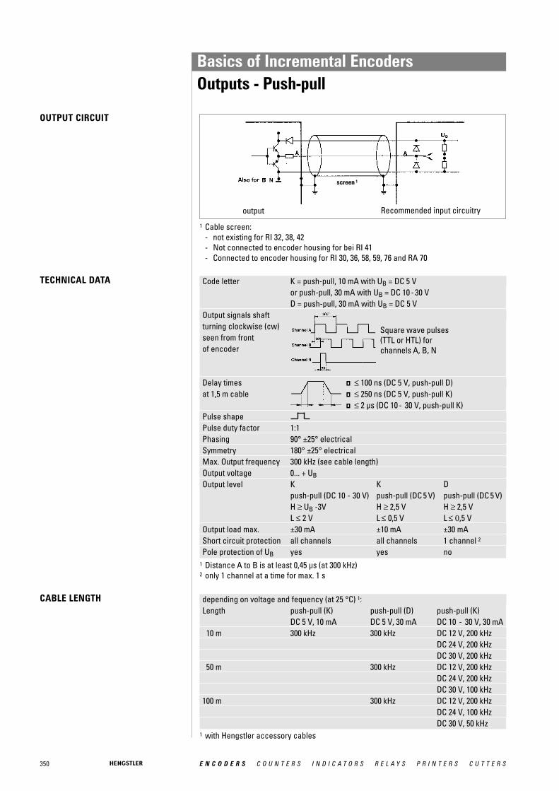
350 E N C O D E R S C O U N T E R S I N D I C A T O R S R E L A Y S P R I N T E R S C U T T E R S
Code letter K = push-pull, 10 mA with UB = DC 5 V or push-pull, 30 mA with UB = DC 10 - 30 VD = push-pull, 30 mA with UB = DC 5 V
Output signals shaftturning clockwise (cw) seen from frontof encoder
Delay times � ≤ 100 ns (DC 5 V, push-pull D)at 1,5 m cable � ≤ 250 ns (DC 5 V, push-pull K)
� ≤ 2 μs (DC 10 - 30 V, push-pull K)Pulse shapePulse duty factor 1:1Phasing 90° ±25° electricalSymmetry 180° ±25° electricalMax. Output frequency 300 kHz (see cable length)Output voltage 0... + UBOutput level K K D
push-pull (DC 10 - 30 V) push-pull (DC 5 V) push-pull (DC 5 V)H ≥ UB -3V H ≥ 2,5 V H ≥ 2,5 VL ≤ 2 V L ≤ 0,5 V L ≤ 0,5 V
Output load max. ±30 mA ±10 mA ±30 mAShort circuit protection all channels all channels 1 channel 2
Pole protection of UB yes yes no
OUTPUT CIRCUIT
TECHNICAL DATA
1 Cable screen:- not existing for RI 32, 38, 42 - Not connected to encoder housing for bei RI 41- Connected to encoder housing for RI 30, 36, 58, 59, 76 and RA 70
Square wave pulses(TTL or HTL) forchannels A, B, N
CABLE LENGTH depending on voltage and fequency (at 25 °C) 1:Length push-pull (K) push-pull (D) push-pull (K)
DC 5 V, 10 mA DC 5 V, 30 mA DC 10 - 30 V, 30 mA10 m 300 kHz 300 kHz DC 12 V, 200 kHz
DC 24 V, 200 kHzDC 30 V, 200 kHz
50 m 300 kHz DC 12 V, 200 kHzDC 24 V, 200 kHzDC 30 V, 100 kHz
100 m 300 kHz DC 12 V, 200 kHzDC 24 V, 100 kHzDC 30 V, 50 kHz
output Recommended input circuitry
1 Distance A to B is at least 0,45 μs (at 300 kHz)2 only 1 channel at a time for max. 1 s
1 with Hengstler accessory cables
screen 1
Basics of Incremental EncodersOutputs - Push-pull
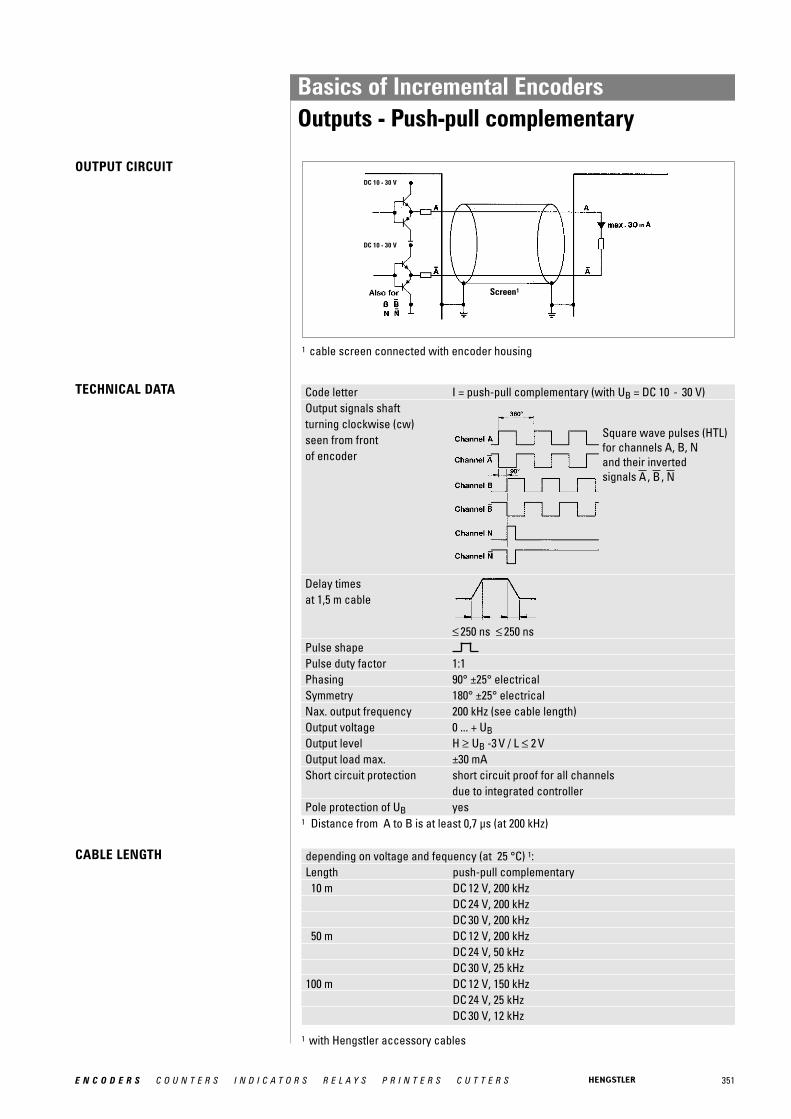
351E N C O D E R S C O U N T E R S I N D I C A T O R S R E L A Y S P R I N T E R S C U T T E R S
Code letter I = push-pull complementary (with UB = DC 10 - 30 V)Output signals shaft turning clockwise (cw)seen from frontof encoder
Delay times at 1,5 m cable
≤ 250 ns ≤ 250 nsPulse shapePulse duty factor 1:1Phasing 90° ±25° electricalSymmetry 180° ±25° electricalNax. output frequency 200 kHz (see cable length)Output voltage 0 ... + UBOutput level H ≥ UB -3 V / L ≤ 2 VOutput load max. ±30 mAShort circuit protection short circuit proof for all channels
due to integrated controllerPole protection of UB yes
depending on voltage and fequency (at 25 °C) 1:Length push-pull complementary10 m DC 12 V, 200 kHz
DC 24 V, 200 kHzDC 30 V, 200 kHz
50 m DC 12 V, 200 kHzDC 24 V, 50 kHzDC 30 V, 25 kHz
100 m DC 12 V, 150 kHzDC 24 V, 25 kHzDC 30 V, 12 kHz
TECHNICAL DATA
CABLE LENGTH
1 cable screen connected with encoder housing
Square wave pulses (HTL)for channels A, B, N and their inverted signals , , NBA
1 Distance from A to B is at least 0,7 μs (at 200 kHz)
1 with Hengstler accessory cables
Screen1
OUTPUT CIRCUITDC 10 - 30 V
DC 10 - 30 V
Basics of Incremental EncodersOutputs - Push-pull complementary
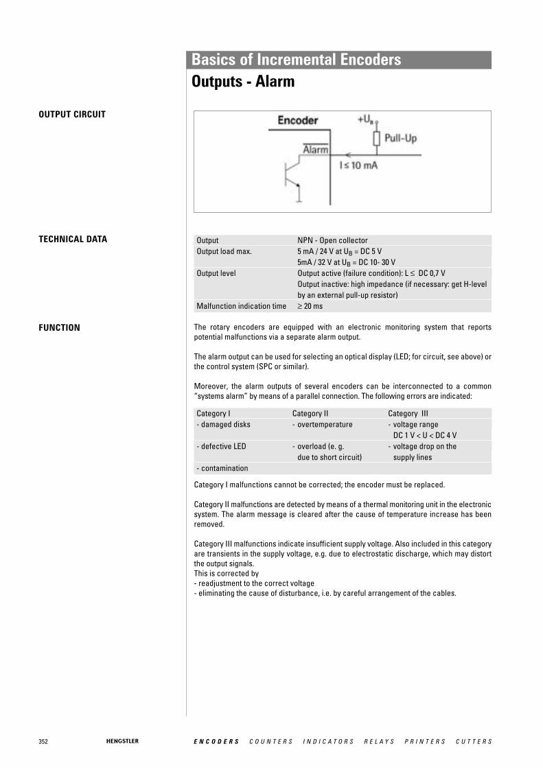
352 E N C O D E R S C O U N T E R S I N D I C A T O R S R E L A Y S P R I N T E R S C U T T E R S
The rotary encoders are equipped with an electronic monitoring system that reportspotential malfunctions via a separate alarm output.
The alarm output can be used for selecting an optical display (LED; for circuit, see above) orthe control system (SPC or similar).
Moreover, the alarm outputs of several encoders can be interconnected to a common“systems alarm” by means of a parallel connection. The following errors are indicated:
Category I Category II Category III- damaged disks - overtemperature - voltage range
DC 1 V < U < DC 4 V- defective LED - overload (e. g. - voltage drop on the
due to short circuit) supply lines- contamination
Output NPN - Open collectorOutput load max. 5 mA / 24 V at UB = DC 5 V
5mA / 32 V at UB = DC 10- 30 VOutput level Output active (failure condition): L ≤ DC 0,7 V
Output inactive: high impedance (if necessary: get H-level by an external pull-up resistor)
Malfunction indication time ≥ 20 ms
OUTPUT CIRCUIT
TECHNICAL DATA
FUNCTION
Category I malfunctions cannot be corrected; the encoder must be replaced.
Category II malfunctions are detected by means of a thermal monitoring unit in the electronicsystem. The alarm message is cleared after the cause of temperature increase has been removed.
Category III malfunctions indicate insufficient supply voltage. Also included in this categoryare transients in the supply voltage, e.g. due to electrostatic discharge, which may distortthe output signals. This is corrected by- readjustment to the correct voltage- eliminating the cause of disturbance, i.e. by careful arrangement of the cables.
Basics of Incremental EncodersOutputs - Alarm

353E N C O D E R S C O U N T E R S I N D I C A T O R S R E L A Y S P R I N T E R S C U T T E R S
1 Voltage drop due to long cable lengths2 Automatic readjustment of the output voltage
(only for power packs with sense input)
The sense wires enable measuring of the actual encoder supply voltage (compensates forvoltage drops due to supply current and cable resistance).Due to the voltage drop in the cables and the voltage supply, the encoder input voltage Uinis less than the power pack output voltage Uout.The present input voltage Uin is now output to the Sense VCC and Sense GND cables andreturns as data to the power pack.The input resistance Ri on the power pack should amount to at least 22 MOhm so that no voltage drop occurs on these cables.In case of power packs with sense input, it is now possible to readjust the output voltage Uoutautomatically.
OUTPUT CIRCUIT
FUNCTION
Basics of Incremental EncodersOutputs - Sense at 5 V RS 422 (T)

SINE-WAVE OPTOASIC TECHNOLOGYBURSTS THE LIMITS
With the introduction of the sine-waveencoder family, Hengstler has taken theopportunity to significantly rework itsOptoAsic technology.
The best features have been maintained and new improvements have been introduced. Onemajor feature that has been retained of course, is the high level of EMC reliability which wehave achieved by integrating almost the complete encoder electronics into one component.
What is new is the integrated offset and amplitude control together with the in-chip opticalsystem adjustment. In the past anybody wanting high quality, accurate sine-wave signals atlow frequencies had to trade in this for bandwidth. We are now able to meet this apparentlycontradictory requirement with our in-built amplitude control. You can't fail to be convincedby a unit which delivers sine-wave signal with harmonic distortion better than 1% at lowspeed and 500 kHz max. frequency.
The advantages are crystal clear: If you need precision at slow speeds you no longer haveto compromise your productivity because the encoder limits the maximum speed of yourmachine e.g. for tool changing processes. You can have both - accuracy and speed.
APPLICATIONS Typical applications:• Machine tools• Printing machines• Gearless elevators• Drives
GENERAL INFORMATION
354 E N C O D E R S C O U N T E R S I N D I C A T O R S R E L A Y S P R I N T E R S C U T T E R S
Basics of Sine-Wave Encoders

355E N C O D E R S C O U N T E R S I N D I C A T O R S R E L A Y S P R I N T E R S C U T T E R S
THE RIS58 SIGNAL QUALITY2
1,81,61,41,2
10,80,60,40,2
020 70 120 170 220 270 320
Signal frequency [kHz]
Harm
onic
dis
torti
on (%
)
The quality of the servo loop is determined to a large extent by the absence of harmonics inthe encoder's sinewave signals, particulary at low speed. In order to achieve high interpolation factors in the sequencing control, the incremental sine signals A and B areavailable with a harmonic distortion significantly under 1% throughout the specified temperature range. This delivers excellent synchronism and a high level of positional accuracy with servo axes.
THE RIS58 SIGNALS
Signals shown at CW rotation with view on shaft's end
The incremental signals A and B and the zero signal R are differential voltage signals. Thedifferential signal level is 1 Vpp. The zero signal appears once per revolution with a peak of0.4 V and reaches its maximum value at the angle where the amplitudes of the A and B signals are equal. All signals have a DC-offset of 2.5 V.
B
A
R
Basics of Sine-Wave EncodersSignals

356 E N C O D E R S C O U N T E R S I N D I C A T O R S R E L A Y S P R I N T E R S C U T T E R S
ABSOLUTE ENCODERS FOLLOW THE LATEST TREND: CHANGE EASILY TO ACURO
Absolute encoders save costs and provideenhanced safety - facts that are obviouslyimportant in complex installations and multi-axis machinery: Time-consuming referenceruns after powering-up the supply voltagehave become a thing of the past for absolute encoders. Hazardous conditionscaused by reference runs (which are alwaysnecessary with incremental encoders) canbe prevented right from the start. Absoluteencoders - too large, too expensive?
A prejudice that is cleared up by ACURO.Even the multi turn version of ACURO is nolarger than most incremental encoders andcosts less than you would expect. And howabout reliability? Due to their complexity,absolute encoders seem to be susceptibleto faults. No problem with ACURO: onceinstalled they will not cause trouble, due tothe highest integration density and use ofextremely reliable technologies to ensuresafe and reliable long-term operation.
The platform concept Hengstler's new ACURO absolute encodersfeature innovative technology, simple ope-rational and optimal functional safety. Theirplatform concept also allows especiallycompact dimensions with a modular design,which always ensures the right version foreach individual application in the field ofmotor feedback and automation enginee-ring. Equipped with the new open BiSSinterface these encoders are a good andfuture oriented investment.
The mechanical construction of ACURO isrugged and precise. Double high-precisionball bearings guarantee reliable long-termoperation even at speeds of up to 12 000 rpm.ACURO is equipped with the commerciallyavailable mechanical interfaces, includingsolid shaft or hub shaft, synchro-flange orclamping flange.
ABSOLUTE ENCODERS ARE DIFFERENTIATED ACCORDING TO:
1 revolution (= 360 °) is coded in n steps.After a rotation of over 360 ° the code isrepeated.
Multiturn version
Singleturn version
Apart from measuring 360 ° (1 revolution)further coded revolutions can be recordede.g for applications in combination withlead srews or timing belts. Hengstler isusing the principle of a mechanical memory(gearbox, which is unmatched in reliabilityand EMC).
Basics of Absolute Encoders ACURO
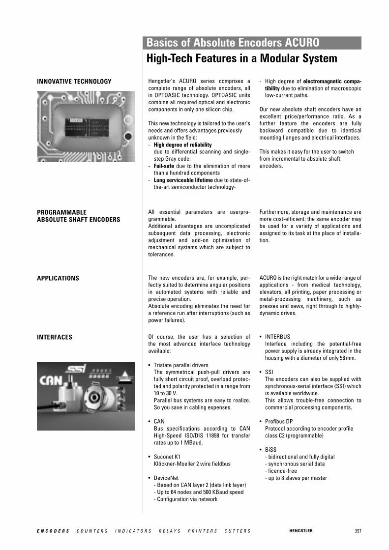
357E N C O D E R S C O U N T E R S I N D I C A T O R S R E L A Y S P R I N T E R S C U T T E R S
Of course, the user has a selection of the most advanced interface technology available:
• Tristate parallel driversThe symmetrical push-pull drivers arefully short circuit proof, overload protec-ted and polarity protected in a range from10 to 30 V.Parallel bus systems are easy to realize.So you save in cabling expenses.
• CANBus specifications according to CAN High-Speed ISO/DIS 11898 for transfer rates up to 1 MBaud.
• Suconet K1Klöckner-Moeller 2 wire fieldbus
• DeviceNet- Based on CAN layer 2 (data link layer)- Up to 64 nodes and 500 KBaud speed- Configuration via network
INNOVATIVE TECHNOLOGY
INTERFACES
APPLICATIONS
PROGRAMMABLEABSOLUTE SHAFT ENCODERS
Hengstler’s ACURO series comprises a complete range of absolute encoders, all in OPTOASIC technology. OPTOASIC unitscombine all required optical and electroniccomponents in only one silicon chip.
This new technology is tailored to the user’sneeds and offers advantages previouslyunknown in the field:- High degree of reliability
due to differential scanning and single-step Gray code.
- Fail-safe due to the elimination of more than a hundred components
- Long serviceable lifetime due to state-of-the-art semiconductor technology-
All essential parameters are userpro-grammable.Additional advantages are uncomplicatedsubsequent data processing, electronicadjustment and add-on optimization ofmechanical systems which are subject totolerances.
The new encoders are, for example, per-fectly suited to determine angular positionsin automated systems with reliable and precise operation.Absolute encoding eliminates the need fora reference run after interruptions (such aspower failures).
- High degree of electromagnetic compa-tibility due to elimination of macroscopiclow-current paths.
Our new absolute shaft encoders have anexcellent price/performance ratio. As a further feature the encoders are fully backward compatible due to identicalmounting flanges and electrical interfaces.
This makes it easy for the user to switchfrom incremental to absolute shaft encoders.
Furthermore, storage and maintenance aremore cost-efficient: the same encoder maybe used for a variety of applications andassigned to its task at the place of installa-tion.
ACURO is the right match for a wide range ofapplications - from medical technology, elevators, all printing, paper processing ormetal-processing machinery, such as presses and saws, right through to highly-dynamic drives.
• INTERBUSInterface including the potential-freepower supply is already integrated in thehousing with a diameter of only 58 mm.
• SSIThe encoders can also be supplied withsynchronous-serial interface (SSI) which is available worldwide.This allows trouble-free connection to commercial processing components.
• Profibus DPProtocol according to encoder profileclass C2 (programmable)
• BiSS- bidirectional and fully digital- synchronous serial data- licence-free- up to 8 slaves per master
Basics of Absolute Encoders ACUROHigh-Tech Features in a Modular System
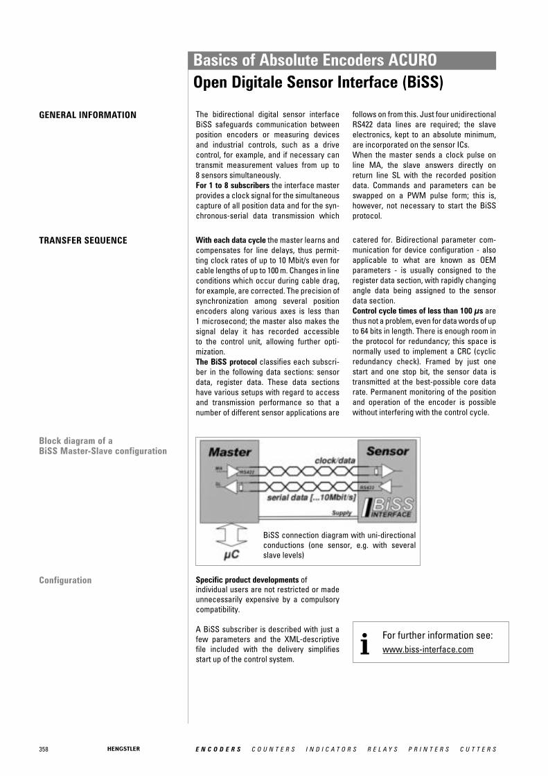
358 E N C O D E R S C O U N T E R S I N D I C A T O R S R E L A Y S P R I N T E R S C U T T E R S
GENERAL INFORMATION The bidirectional digital sensor interfaceBiSS safeguards communication betweenposition encoders or measuring devicesand industrial controls, such as a drive control, for example, and if necessary cantransmit measurement values from up to 8 sensors simultaneously.For 1 to 8 subscribers the interface masterprovides a clock signal for the simultaneouscapture of all position data and for the syn-chronous-serial data transmission which
follows on from this. Just four unidirectionalRS422 data lines are required; the slaveelectronics, kept to an absolute minimum,are incorporated on the sensor ICs. When the master sends a clock pulse online MA, the slave answers directly onreturn line SL with the recorded positiondata. Commands and parameters can beswapped on a PWM pulse form; this is,however, not necessary to start the BiSSprotocol.
Configuration Specific product developments ofindividual users are not restricted or madeunnecessarily expensive by a compulsorycompatibility.
A BiSS subscriber is described with just afew parameters and the XML-descriptivefile included with the delivery simplifiesstart up of the control system.
With each data cycle the master learns andcompensates for line delays, thus permit-ting clock rates of up to 10 Mbit/s even forcable lengths of up to 100 m. Changes in lineconditions which occur during cable drag,for example, are corrected. The precision ofsynchronization among several positionencoders along various axes is less than 1 microsecond; the master also makes thesignal delay it has recorded accessible to the control unit, allowing further opti-mization.The BiSS protocol classifies each subscri-ber in the following data sections: sensordata, register data. These data sectionshave various setups with regard to accessand transmission performance so that anumber of different sensor applications are
catered for. Bidirectional parameter com-munication for device configuration - alsoapplicable to what are known as OEM parameters - is usually consigned to theregister data section, with rapidly changingangle data being assigned to the sensordata section. Control cycle times of less than 100 μs arethus not a problem, even for data words of upto 64 bits in length. There is enough room inthe protocol for redundancy; this space isnormally used to implement a CRC (cyclicredundancy check). Framed by just onestart and one stop bit, the sensor data istransmitted at the best-possible core datarate. Permanent monitoring of the positionand operation of the encoder is possiblewithout interfering with the control cycle.
Block diagram of aBiSS Master-Slave configuration
TRANSFER SEQUENCE
BiSS connection diagram with uni-directionalconductions (one sensor, e.g. with severalslave levels)
For further information see:www.biss-interface.comi
Basics of Absolute Encoders ACUROOpen Digitale Sensor Interface (BiSS)
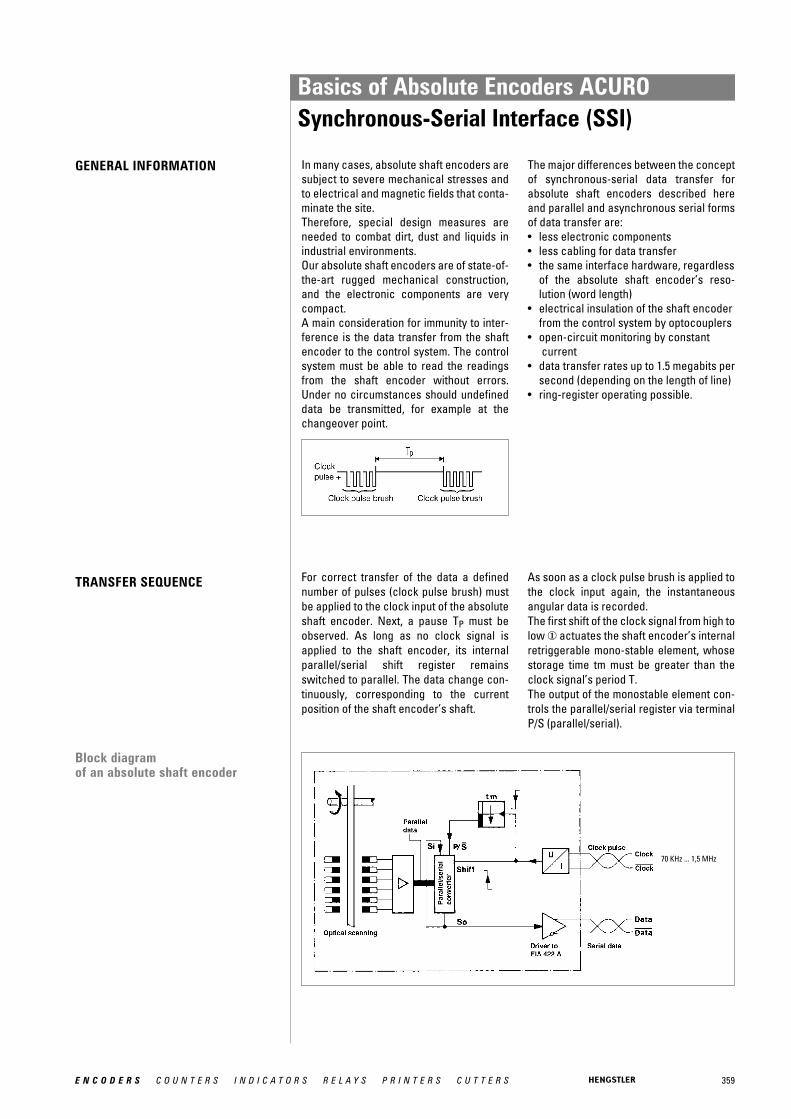
359E N C O D E R S C O U N T E R S I N D I C A T O R S R E L A Y S P R I N T E R S C U T T E R S
GENERAL INFORMATION In many cases, absolute shaft encoders aresubject to severe mechanical stresses andto electrical and magnetic fields that conta-minate the site.Therefore, special design measures areneeded to combat dirt, dust and liquids inindustrial environments.Our absolute shaft encoders are of state-of-the-art rugged mechanical construction,and the electronic components are verycompact.A main consideration for immunity to inter-ference is the data transfer from the shaftencoder to the control system. The controlsystem must be able to read the readingsfrom the shaft encoder without errors.Under no circumstances should undefineddata be transmitted, for example at thechangeover point.
The major differences between the conceptof synchronous-serial data transfer forabsolute shaft encoders described hereand parallel and asynchronous serial formsof data transfer are:• less electronic components• less cabling for data transfer• the same interface hardware, regardless
of the absolute shaft encoder’s reso- lution (word length)
• electrical insulation of the shaft encoder from the control system by optocouplers
• open-circuit monitoring by constantcurrent
• data transfer rates up to 1.5 megabits per second (depending on the length of line)
• ring-register operating possible.
For correct transfer of the data a definednumber of pulses (clock pulse brush) mustbe applied to the clock input of the absoluteshaft encoder. Next, a pause TP must beobserved. As long as no clock signal isapplied to the shaft encoder, its internalparallel/serial shift register remains switched to parallel. The data change con-tinuously, corresponding to the currentposition of the shaft encoder’s shaft.
As soon as a clock pulse brush is applied tothe clock input again, the instantaneousangular data is recorded.The first shift of the clock signal from high tolow ① actuates the shaft encoder’s internalretriggerable mono-stable element, whosestorage time tm must be greater than theclock signal’s period T.The output of the monostable element con-trols the parallel/serial register via terminalP/S (parallel/serial).
70 KHz ... 1,5 MHz
Block diagramof an absolute shaft encoder
TRANSFER SEQUENCE
Basics of Absolute Encoders ACUROSynchronous-Serial Interface (SSI)

360 E N C O D E R S C O U N T E R S I N D I C A T O R S R E L A Y S P R I N T E R S C U T T E R S
With the first shift of the clock signal fromlow to high ② the most significant bit (MSB)of the angular data is applied to the shaftencoder’s serial output.With each succeeding rising edge, the nextless significant bit is shifted to the data out-put.After transmission of the least significantbit (LSB) the Alarm bit or other special bitsare transferred, depending on configura-tion. Then the data line switches to low ③until the time tm has passed.
A further transfer of data cannot be starteduntil the data line switches to high ④ again.If the clock pulse sequence is not interrup-ted at point ③, the ring-register mode isactivated automatically. This means thatthe data stored at the first clock pulse tran-sition ① are returned to the serial input Sivia the terminal SO. As long as the clockpulse is not interrupted at ③, the data canbe read out as often as wanted (multipletransfer).
T = clock pulse periodtm = storage time of monostable elementtm ranging from 10 μs to 30 μstv = 100 ns
The number of clock pulses necessary fordata transfer is independent of the reso-lution of the absolute shaft encoder.
The clock signal can be interrupted at anypoint, or continued in ring-register mode forrepeated polling.
Basics of Absolute Encoders ACUROSynchronous-Serial Interface (SSI)
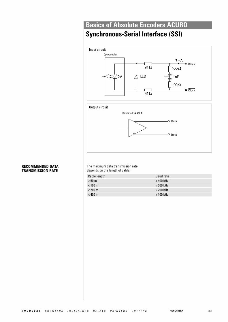
361E N C O D E R S C O U N T E R S I N D I C A T O R S R E L A Y S P R I N T E R S C U T T E R S
Input circuit
Output circuit
Driver to EIA 422 A
RECOMMENDED DATA TRANSMISSION RATE
Cable length Baud rate< 50 m < 400 kHz< 100 m < 300 kHz< 200 m < 200 kHz< 400 m < 100 kHz
The maximum data transmission ratedepends on the length of cable:
Optocoupler
Clock
Clock
Data
Data
Basics of Absolute Encoders ACUROSynchronous-Serial Interface (SSI)
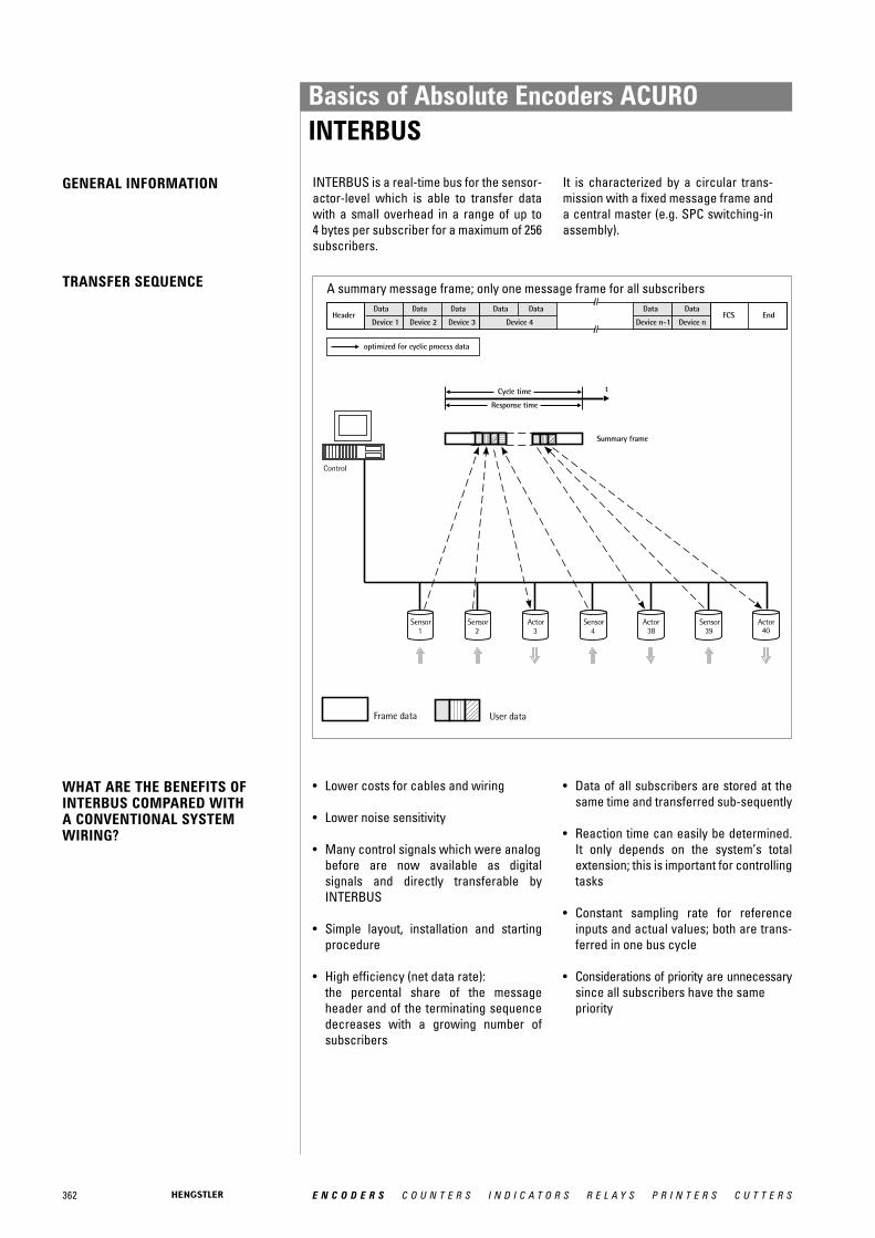
362 E N C O D E R S C O U N T E R S I N D I C A T O R S R E L A Y S P R I N T E R S C U T T E R S
WHAT ARE THE BENEFITS OFINTERBUS COMPARED WITH A CONVENTIONAL SYSTEMWIRING?
INTERBUS is a real-time bus for the sensor-actor-level which is able to transfer datawith a small overhead in a range of up to 4 bytes per subscriber for a maximum of 256subscribers.
It is characterized by a circular trans-mission with a fixed message frame and a central master (e.g. SPC switching-inassembly).
A summary message frame; only one message frame for all subscribers
• Lower costs for cables and wiring
• Lower noise sensitivity
• Many control signals which were analogbefore are now available as digital signals and directly transferable by INTERBUS
• Simple layout, installation and starting procedure
• High efficiency (net data rate): the percental share of the message header and of the terminating sequence decreases with a growing number of subscribers
• Data of all subscribers are stored at the same time and transferred sub-sequently
• Reaction time can easily be determined. It only depends on the system’s total extension; this is important for controlling tasks
• Constant sampling rate for reference inputs and actual values; both are trans-ferred in one bus cycle
• Considerations of priority are unnecessarysince all subscribers have the same priority
GENERAL INFORMATION
TRANSFER SEQUENCE
Basics of Absolute Encoders ACUROINTERBUS
363E N C O D E R S C O U N T E R S I N D I C A T O R S R E L A Y S P R I N T E R S C U T T E R S
ENCOM USER GROUP
• No system-parameter definition before starting procedure
• Data integrity is secured by 16-bit-CRC(according to CCITT polynomial) done for each transmission
• Sophisticated diagnostic software for the central bus controller: a point of error can specifically be isolated; in each case of malfunction there is a possibility to close the circular system in every single bus clip.
Devices with an INTERBUS interface forprocess control are now available frommore than 200 manufacturers.
Encoder manufacturers are joined togetherin the ENCOM user group; drive manu-facturers in DRIVECOM.
The user groups shall maximize the benefitfor the customer by standardization of datatransmission.
There is a high availability of devices withINTERBUS interface, and the bus mode hasalready been successful in industrial use.
The following device classes defined byENCOM are used for absolute shaft encoders:
Class 2 (K2):• 32-bit process data• Binary• Right-justified• Readable only• No control bits or status bits
Class 3 (K3):• 32-bit process data• Coded according to manufacturer
specifications• Right-justified• 7 status bits and control bits
Basics of Absolute Encoders ACUROINTERBUS
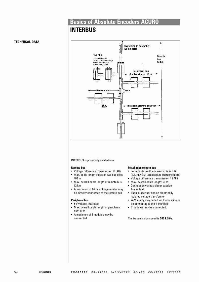
364 E N C O D E R S C O U N T E R S I N D I C A T O R S R E L A Y S P R I N T E R S C U T T E R S
TECHNICAL DATA
INTERBUS is physically divided into:
Remote bus• Voltage difference transmission RS 485• Max. cable length between two bus clips:
400 m• Max. overall cable length of remote bus:
13 km• A maximum of 64 bus clips/modules may
be directly connected to the remote bus
Peripheral bus• 5 V voltage interface• Max. overall cable length of peripheral
bus: 10 m• A maximum of 8 modules may be
connected
Installation remote bus• For modules with enclosure class IP65
(e.g. HENGSTLER absolute shaft encoders)• Voltage difference transmission RS 485• Max. overall cable length: 50 m• Connection via bus clip or passive
T-manifold• Each subscriber has an electrically
isolated voltage transformer• 24 V supply may be led via the bus line or
be connected to the T-manifold• 8 modules may be connected.
The transmission speed is 500 kBit/s.
Basics of Absolute Encoders ACUROINTERBUS
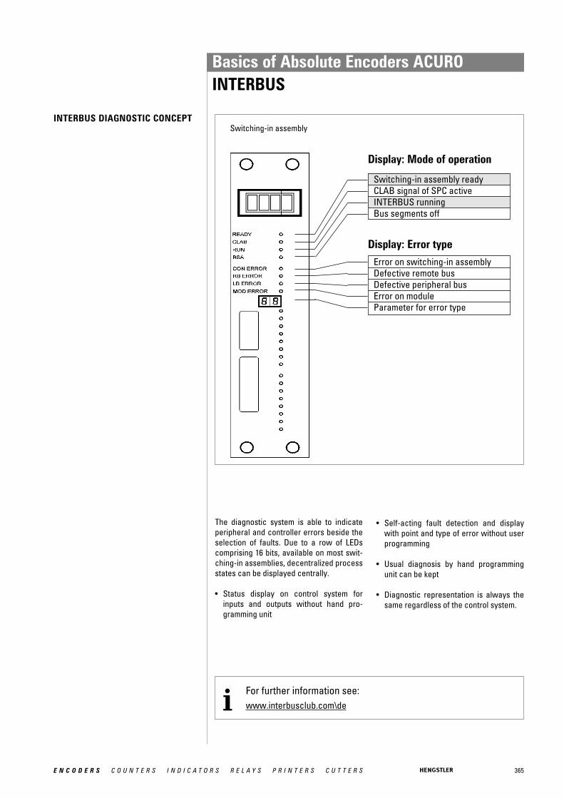
365E N C O D E R S C O U N T E R S I N D I C A T O R S R E L A Y S P R I N T E R S C U T T E R S
INTERBUS DIAGNOSTIC CONCEPT
The diagnostic system is able to indicateperipheral and controller errors beside theselection of faults. Due to a row of LEDscomprising 16 bits, available on most swit-ching-in assemblies, decentralized processstates can be displayed centrally.
• Status display on control system for inputs and outputs without hand pro-gramming unit
• Self-acting fault detection and display with point and type of error without user programming
• Usual diagnosis by hand programming unit can be kept
• Diagnostic representation is always the same regardless of the control system.
Switching-in assembly
Display: Mode of operation
Display: Error typeError on switching-in assembly Defective remote busDefective peripheral busError on moduleParameter for error type
For further information see:www.interbusclub.com\dei
Switching-in assembly readyCLAB signal of SPC activeINTERBUS runningBus segments off
Basics of Absolute Encoders ACUROINTERBUS

366 E N C O D E R S C O U N T E R S I N D I C A T O R S R E L A Y S P R I N T E R S C U T T E R S
GENERAL INFORMATION
FIELD OF APPLICATION
The AC 58 is an absolute shaft encoder(encoder, angle encoder). The versiondescribed in this technical manual sends itscurrent position to another station via the"CAN-bus" transmission medium (physi-cally: screened and twisted two-wire line).
The serial bus system CAN (Controller AreaNetwork), which had been originally deve-loped by Bosch/ Intel for automotive uses,is gaining ground in industrial automationtechnology. The system is multimaster-compatible, i.e. several CAN- stations areable to request the bus at the same time.The message with the highest priority(determined by the identifier) will be receivedimmediately.
The data transfer is regulated by the mes-sage's priority. Within the CAN system,there are no transport addresses, but mes-sage identifiers. The message which isbeing sent can be received by all stations atthe same time (broadcast).
By means of a special filter methods, thestation only accepts the relevant messa-ges. The identifier transmitted with themessage is the basis for the decision as towhether the message will be accepted ornot.
The bus coupler is standardised according tothe international standard ISO-DIS 11898(CAN High Speed) standard and allows datato be transferred at a maximum rate of 1MBit/ s. The most significant feature of theCAN-protocol is its high level of transmis-sion reliability (Hamming distance = 6).
The CAN-Controller Intel 82527 used in the encoder is basic as well as full-CANcompatible and supports the CAN-specifi-cation 2.0 part B (standard protocol with11-bit- identifier as well as extended proto-col with 29-bit identifier). Up to now, only 11-bit identifiers have been used for CANopen.
In systems, where the position of a drive orof any other part of a machine has to berecorded and signalled to the controlsystem, the AC 58 can assume this function.The AC 58 can resolve, for instance, positio-ning tasks by sending the check-back signal concerning the present drive position via the CAN bus to the positioningunit.
Basics of Absolute Encoders ACUROCANopen

367E N C O D E R S C O U N T E R S I N D I C A T O R S R E L A Y S P R I N T E R S C U T T E R S
CANOPEN COMMUNICATIONMODEL AND PROFILE
For the following devices, profiles already exist::• CiA Draft Standard Proposal 401 for Input/Output Modules• CiA Draft Standard Proposal 402 for Drives and Motion Control• CiA Work Item 403 for Human-Machine Interfaces• CiA Work Draft 404 for Closed-Loop Controllers and Transformers• CiA Work Item 405 for IEC-1131 Interfaces• CiA Draft Standard Proposal 406 for Encoders• CiA Work Item 407 for Public Transport• CiA Work Item 408 for Fork-Lifts
Layer 1 (Physical Layer): ISO-DIS 11898 (CAN High Speed)
Layer 2 (Data Link Layer): ISO-DIS 11898 (CAN High Speed)
Layer 7 (Application Layer): CiA DS 301 (CANopen CAL-based Communication Profile)+ Device profile CiA DS 4xx (CANopen Device Profile for xx)
Basics of Absolute Encoders ACUROCANopen
368 E N C O D E R S C O U N T E R S I N D I C A T O R S R E L A Y S P R I N T E R S C U T T E R S
THE CANOPEN PROFILE
THE ENCODER DEVICE PROFILE(CIA DSP 406)
About two and a half years after the CiA, theassociation of the user and manufacturer ofCAN products, had adopted the CANApplication Layer (CAL), CANopen and therespective device profiles paved the wayfor the development of open systems.CANopen has been developed under thetechnical direction of the SteinbeisTransfer Centre for Automation (STAReutlingen; Germany) on the basis of thelayer 7 CAL specification.Compared with CAL, CANopen only provi-des the functions needed for this specialpurpose. CANopen is thus a part of CALwhich has been optimised for applicationpurposes and allows for a simpler systemstructure as well as for simpler devices.CANopen has been optimised for a quicktransfer of data in real-time systems andhas been standardised for different deviceprofiles.The CAN in Automation (CiA) association ofusers and manufacturers is responsible forthe establishing and the standardisation ofthe respective profiles.
The RA58 with CANopen meets the require-ments laid down in the communication pro-file (CiA DS 301) and in the device profile forencoders.
CANopen allows for:• auto configuration of the network,• comfortable access to all device
parameters.• synchronisation of the devices,• cyclical and event-controlled process
data processing,• simultaneous data input and output.
CANopen uses four communication objects(COB) with different features:• Process Data Objects (PDO) for
real-time data• Service Data Objects (SDO) for the
transfer of parameters and programs• Network Management (NMT,
Life-Guarding)• predefined objects (for synchronisation,
time stamp, emergency message)
All device parameters are stored in anobject directory. The object directory contains the description, data type andstructure of the parameters as well as theiraddresses (index).The directory consists of three parts: com-munication profile parameters, device pro-file parameters and manufacturer specificparameters.
This profile describes a binding, but manu-facturer-independent definition of the inter-face for encoders. The profile not only defi-nes which CANopen functions are to beused, but also how they are to be used. Thisstandard permits an open and manufactu-rer-independent bus system.
The device profile consists of two objectcategories• the standard category C1 describes all
the basic functions the shaft encoder must contain
• the extended category C2 contains a variety of additional functions which either have to be supported by category C2 shaft encoders (mandatory) or which are optional. Category C2 devices thus contain all C1 and C2 mandatory functions as wellas, depending on the manufacturer, further optional functions.
Furthermore, an addressable area is defined in the profile, to which, dependingon the manufacturer, different functionscan be assigned.
Basics of Absolute Encoders ACUROCANopen

369E N C O D E R S C O U N T E R S I N D I C A T O R S R E L A Y S P R I N T E R S C U T T E R S
DATA TRANSFER
COB IDENTIFIER
NODE NUMBER
In CANopen, the data is transferred bymeans of two different communicationtypes (COB = Communication Object) withdifferent features:
• Process Data Objects (PDO)• Service Data Objects (SDO)
The priority of the message objects is deter-mined by the COB identifier.
The process data objects (PDO) serve thehighly dynamic exchange of real-time data(e.g. position of the shaft encoder) with amaximum length of 8 Byte. This data istransferred with high priority (low COBidentifier). PDOs are broadcast messagesand put their information simultaneously atthe disposal of all desired receivers.
The service data objects (SDO) form thecommunication channel for the transfer ofdevice parameters (e.g. programming of theshaft encoders' resolution). Since theseparameters are transferred acyclically (e.g.only once when running up the network),the SDO objects have a low priority (highCOB identifier).
For an easier administration of the identifiers, CANopen uses the "Predefined master/SlaveConnection Set"). In this case, all identifiers with standard values are defined in the objectdirectory. However, these identifiers can be modified according to the customers' needs viaSDO access.
The 11-bit identifier consists of a 4 Bit function code and a 7 Bit node number.
Bit-No. 10 9 8 7 6 5 4 3 2 1 0Type Function code Node numberAssignment 1 x x x x 0 0 x x x x x
1 x = binary value can be selected freely 0 or 1); 0 = 0 value is fixed
The higher the value of the COB identifier, the lower the identifier’s priority!
The 7-bit node number is set by means of the hardware via the 5 DIP switches on the encoder’s back.
For further information see CAN user organisation:www.can-cia.dei
Basics of Absolute Encoders ACUROCANopen
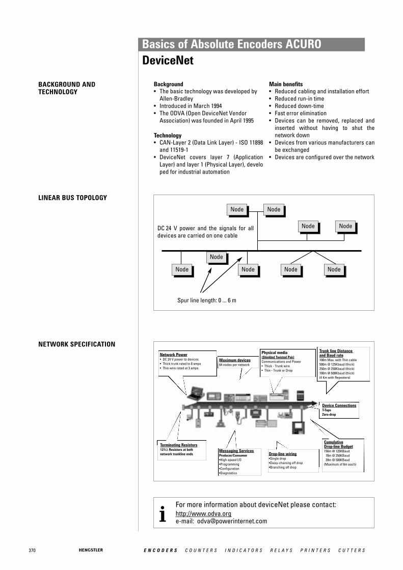
370 E N C O D E R S C O U N T E R S I N D I C A T O R S R E L A Y S P R I N T E R S C U T T E R S
Background• The basic technology was developed by
Allen-Bradley• Introduced in March 1994• The ODVA (Open DeviceNet Vendor
Association) was founded in April 1995
Technology• CAN-Layer 2 (Data Link Layer) - ISO 11898
and 11519-1• DeviceNet covers layer 7 (Application
Layer) and layer 1 (Physical Layer), developed for industrial automation
DC 24 V power and the signals for alldevices are carried on one cable
notenNode notenNode
notenNode notenNode
notenNodenotenNodenotenNode
notenNode
notenNode
Spur line length: 0 ... 6 m
Main benefits• Reduced cabling and installation effort• Reduced run-in time• Reduced down-time• Fast error elimination• Devices can be removed, replaced and
inserted without having to shut the network down
• Devices from various manufacturers can be exchanged
• Devices are configured over the network
NETWORK SPECIFICATION
Maximum devices64 nodes per network
Device ConnectionsT-TapsZero-drop
Physical media(Shielded Twisted Pair)Communications and Power• Thick - Trunk wire• Thin - Trunk or Drop
CumulativeDrop-line Budget156m @ 125KBaud
78m @ 250KBaud39m @ 500KBaud
(Maximum of 6m each)
Drop-line wiring•Single drop•Daisy-chaining off drop•Branching off drop
Terminating Resistors121Ω Resistors at bothnetwork trunkline ends
BACKGROUND ANDTECHNOLOGY
LINEAR BUS TOPOLOGY
Network Power• DC 24 V power to devices• Thick trunk rated to 8 amps• Thin wire rated at 3 amps
Messaging ServicesProducer/Consumer•High-speed I/O•Programming•Configuration•Diagnostics
Trunk line Distance and Baud rate100m Max. with Thin cable500m @ 125Kbaud (thick)250m @ 250Kbaud (thick)100m @ 500Kbaud (thick)(4 Km with Repeaters)
For more information about deviceNet please contact:http://www.odva.orge-mail: [email protected]
Basics of Absolute Encoders ACURODeviceNet
371E N C O D E R S C O U N T E R S I N D I C A T O R S R E L A Y S P R I N T E R S C U T T E R S
GENERAL INFORMATION The basic functions of the PROFIBUS DP are here only described in extracts. Foradditional information, please refer to thestandards on PROFIBUS DP, i.e. DIN 19245-3 and EN 50170 respectively.
INTRODUCTION The AC 58 is an absolute shaft encoder(encoder, angle encoder). The versiondescribed in this manual sends its currentposition to another station via the transmis-sion medium "PROFIBUS DP" (physically:screened and twisted pair line). The AC 58supports all class 1 and 2 functions listed inthe encoder profile.
PROFIBUS-DP is manufacturer indepen-dent, open field bus standard for a variety ofapplications in the field of production, pro-cess and building services automation. Therequirements of openness and indepen-dence from the manufacturer are stipulatedin the European standard EN 50 170.
PROFIBUS-DP permits the communicationof devices produced by different manufac-turers without any particular adaptations ofthe interfaces.PROFIBUS DP is a special standard versionfor a quick data exchange within the fieldlevel which has been optimised in terms ofspeed and low connection costs. Centralcontrol systems like, for example SPC/ PCcommunicate via a quick, serial connectionwith local field devices like drives, valves,or encoders. The data exchange betweenthese devices is predominantly cyclical.The communication functions required forthis exchange are determined by the basicfunctions of the PROFIBUS DP according tothe EN 50 170 European standard.
FIELD OF APPLICATION In systems, where the position of a drive orof any other part of a machine has to berecorded and signalled to the controlsystem, the AC 58 can assume this function.
The AC 58 can resolve, for instance, positio-ning tasks by sending the checkback signalconcerning the present drive position viathe PROFIBUS DP to the positioning unit.
BASIC FUNCTIONS OF THE PROFIBUS-DP
The central control system (master) cycli-cally reads out the input information fromthe slaves and writes the output informationto the slaves. For this purpose, the buscycle time has to be shorter than the program cycle time of the central SPC,which amounts to approx. 10 ms for variousapplications.
Apart from the cyclical user data transfer,the PROFIBUS DP version also disposes ofpowerful functions for diagnosis and initialoperation procedures. The data traffic iscontrolled by watchdog functions on boththe slave and the master side. The followingtable summarises the basic functions of thePROFIBUS DP.
Basics of Absolute Encoders ACUROProfibus-DP

372 E N C O D E R S C O U N T E R S I N D I C A T O R S R E L A Y S P R I N T E R S C U T T E R S
Transmission technology: • RS-485 twisted pair line• Baud rates ranging from 9.6 kBit/s up to 12 MBit/s
Bus access: • Token passing procedure between the masters andmaster-slave procedures for slaves
• Monomaster or multimaster systems possible• master and slave devices, max. of 126 stations at a
single busCommunication: • Point-to-point (user data communication) or multicast
(control commands)• cyclical master-slave user data communication and
acyclical master-master data transferOperating state: • Operate: cyclical transfer of input and output data
• Clear: The input data are read, the output data remainin the safe status
• Stop: only master-master data transfer is possibleSynchronisation: • Control commands enable a synchronisation of the input
and output data• Sync mode: Output data are being synchronised
Functionality: • Cyclical user data transfer between DP master and DPslave(s)
• Single DP slaves are dynamically activated or deactivated• Control of the DP slave's configuration. Powerful
diagnostic functions, 3 stepped diagnostic message levels.• Synchronisation of in- and/ or output• Address assignment for the DP slaves via the bus• Configuration of the DP masters (DPM1) via the bus• Maximum of 246 byte input and output data per DP slave
possibleProtection functions: • All messages are transferred with a hamming distance
of HD=4• Response control at the DP slaves• Access protection of the DP slaves' input/ output• Monitoring of the user data communication with
adjustable control timer at the masterDevice types: • DP master class 2 (DPM2), e.g. programming/ project
planning devices• DP master class 1 (DPM1), e.g. central automation devices
like SPC, PC• DP slave e. g. devices with binary or analogue input/
output, drives, valves
ESSENTIALFEATURES/SPEED
The PROFIBUS DP only requires approx.1 ms at a speed of 12 MBit/s in order totransfer 512 Bit input and 512 Bit output databy means of 32 stations. The following diagram shows the usualPROFIBUS DP transfer time interval in rela-tion to the number of stations as well as thetransmission speed. The high speed can beabove all explained by the fact that the inputand output data within a message cycle aretransferred by using the layer 2 SRD service(Send and Receive Data Service).
Diagnostic function: The comprehensive diagnostic functions ofPROFIBUS DP allow a quick localisation ofthe errors. The diagnostic messages aretransferred by means of the bus and areassembled at the master. They are subdivi-ded in three levels:
Basics of Absolute Encoders ACUROProfibus-DP
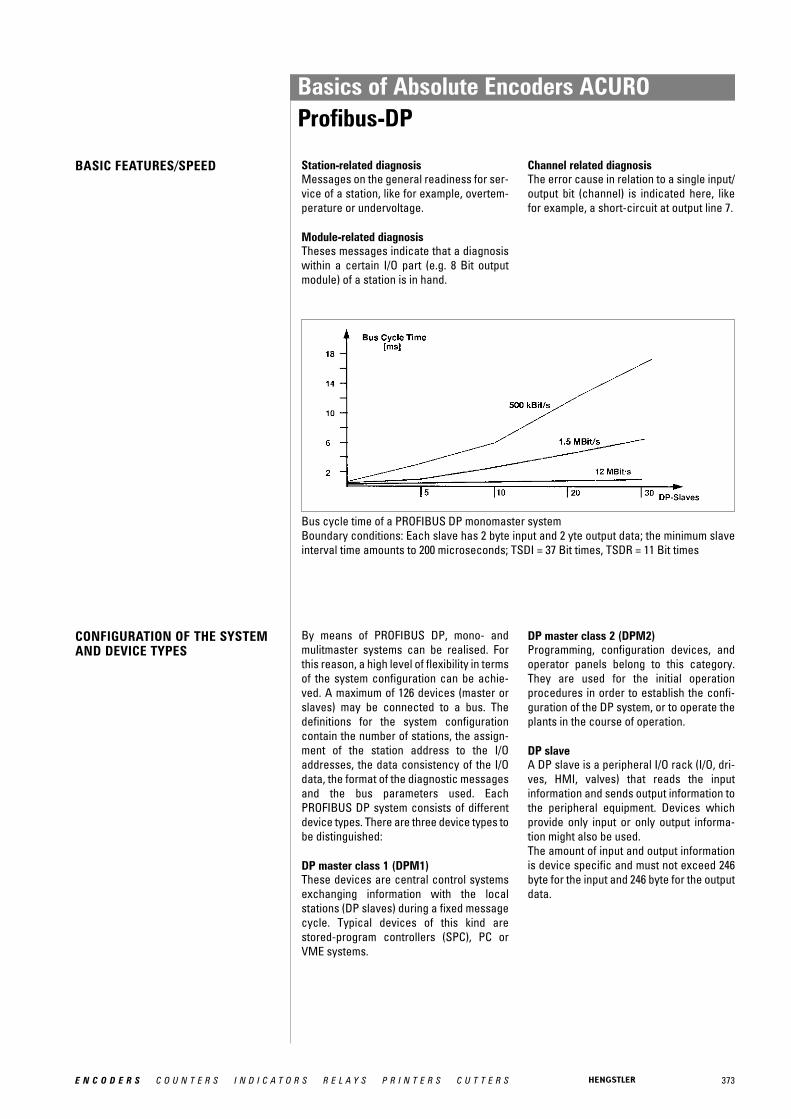
373E N C O D E R S C O U N T E R S I N D I C A T O R S R E L A Y S P R I N T E R S C U T T E R S
BASIC FEATURES/SPEED
CONFIGURATION OF THE SYSTEMAND DEVICE TYPES
By means of PROFIBUS DP, mono- andmulitmaster systems can be realised. Forthis reason, a high level of flexibility in termsof the system configuration can be achie-ved. A maximum of 126 devices (master orslaves) may be connected to a bus. Thedefinitions for the system configurationcontain the number of stations, the assign-ment of the station address to the I/Oaddresses, the data consistency of the I/Odata, the format of the diagnostic messagesand the bus parameters used. Each PROFIBUS DP system consists of differentdevice types. There are three device types tobe distinguished:
DP master class 1 (DPM1)These devices are central control systemsexchanging information with the local stations (DP slaves) during a fixed messagecycle. Typical devices of this kind are stored-program controllers (SPC), PC orVME systems.
DP master class 2 (DPM2)Programming, configuration devices, andoperator panels belong to this category.They are used for the initial operation procedures in order to establish the confi-guration of the DP system, or to operate theplants in the course of operation.
DP slaveA DP slave is a peripheral I/O rack (I/O, dri-ves, HMI, valves) that reads the input information and sends output information tothe peripheral equipment. Devices which provide only input or only output informa-tion might also be used.The amount of input and output informationis device specific and must not exceed 246byte for the input and 246 byte for the outputdata.
Station-related diagnosisMessages on the general readiness for ser-vice of a station, like for example, overtem-perature or undervoltage.
Module-related diagnosisTheses messages indicate that a diagnosiswithin a certain I/O part (e.g. 8 Bit outputmodule) of a station is in hand.
Channel related diagnosisThe error cause in relation to a single input/output bit (channel) is indicated here, likefor example, a short-circuit at output line 7.
Bus cycle time of a PROFIBUS DP monomaster systemBoundary conditions: Each slave has 2 byte input and 2 yte output data; the minimum slaveinterval time amounts to 200 microseconds; TSDI = 37 Bit times, TSDR = 11 Bit times
Basics of Absolute Encoders ACUROProfibus-DP
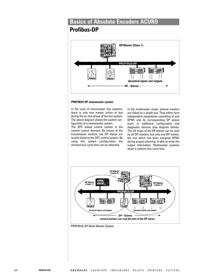
374 E N C O D E R S C O U N T E R S I N D I C A T O R S R E L A Y S P R I N T E R S C U T T E R S
PROFIBUS DP monomaster system
In the case of monomaster bus systems,there is only one master active at busduring the on-line phase of the bus system.The above diagram shows the system con-figuration of a monomaster system. The SPC based control system is the central control element. By means of thetransmission medium, the DP slaves arelocally linked to the SPC control system. Byusing this system configuration, the shortest bus cycle time can be obtained.
PROFIBUS-DP Multi-Master System
In the multimaster mode, several mastersare linked to a single bus. They either formindependent subsystems consisting of oneDPM1 and its corresponding DP slaveseach, or additional configuration and diagnostic devices (see diagram below).The I/O maps of the DP slaves can be readby all DP masters, but only one DP master,the one which has been assigned DPM1during project planning, is able to write theoutput information. Multimaster systemsattain a medium bus cycle time.
DP-Master (Class 1)
decentral inputs and outputs
decentral inputs and outputs decentral inputs and outputs
several masters can read the data of the DP slaves
Basics of Absolute Encoders ACUROProfibus-DP

375E N C O D E R S C O U N T E R S I N D I C A T O R S R E L A Y S P R I N T E R S C U T T E R S
SYSTEM PERFORMANCE In order to obtain a high level of exchange-ability between the devices, the systemperformance of PROFIBUS DP has alsobeen standardised. It is mainly determinedby the operational status of the DPM1.
The DPM1 can either be controlled locallyor via the bus by the project planningdevice. The following three main states canbe distinguished:
StopThere is no data traffic between DPM1 andthe DP slaves.
ClearThe DPM1 reads the input information ofthe DP slaves and maintains the safe statusof the DP slaves' output.
OperateThe DPM1 has entered the data transferphase. In case of a cyclical data traffic, theinput is read by the DP slaves while the out-put is transferred to the DP slaves.
After an error has occurred during the datatransfer phase of the DPM1, like for example,the failure of a DP slave, the response of thesystem is determined by the operatingparameter "Auto Clear".
If this parameter has been set to true, theDPM1 will set the output of all the respec-tive DP slaves to the safe status, as soon asa DP slave is no longer available for userdata communication. Afterwards, theDPM1 changes to the clear status.
If this parameter is = false, the DPM1remains, even if an error occurs, in the ope-rate status, and the user can determine theresponse of the system at his own discre-tion.
CYCLICAL DATA TRANSFER BETWEEN DPM1 AND THE DP SLAVES
The data traffic between the DPM1 and therespective DP slaves is automatically hand-led by the DPM1 in a fixed, recurring order.When configuring the bus system, the userassigns a DP slave to the DPM1. In addition,the slaves to be included in- or excludedfrom the user data communication are defi-ned.
The data traffic between the DPM1 and theDP slaves is subdivided in parametrisation,configuration, and data transfer phases.Before including a DP slave in the datatransfer phase, the DPM1 checks during theparametrisation and configuration phase,whether the planned set configuration corresponds to the actual configuration ofthe device.
For this check, the device type, the informa-tion on the format and the length as well asthe number of input and output lines have tobe correct. The user thus obtains a reliableprotection against parametrisation errors.In addition to the user communication,which is automatically executed by theDPM1, the user may request the new parametrisation data to be sent to the DPslaves.
Basics of Absolute Encoders ACUROProfibus-DP
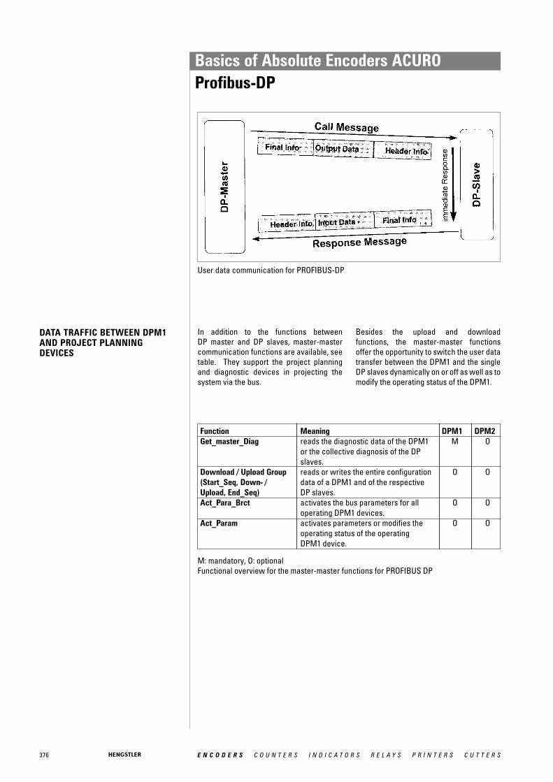
376 E N C O D E R S C O U N T E R S I N D I C A T O R S R E L A Y S P R I N T E R S C U T T E R S
DATA TRAFFIC BETWEEN DPM1AND PROJECT PLANNING DEVICES
Function Meaning DPM1 DPM2Get_master_Diag reads the diagnostic data of the DPM1 M O
or the collective diagnosis of the DPslaves.
Download / Upload Group reads or writes the entire configuration O O(Start_Seq, Down- / data of a DPM1 and of the respectiveUpload, End_Seq) DP slaves.Act_Para_Brct activates the bus parameters for all O O
operating DPM1 devices.Act_Param activates parameters or modifies the O O
operating status of the operatingDPM1 device.
In addition to the functions between DP master and DP slaves, master-mastercommunication functions are available, seetable. They support the project planningand diagnostic devices in projecting thesystem via the bus.
Besides the upload and download functions, the master-master functionsoffer the opportunity to switch the user datatransfer between the DPM1 and the singleDP slaves dynamically on or off as well as tomodify the operating status of the DPM1.
User data communication for PROFIBUS-DP
M: mandatory, O: optionalFunctional overview for the master-master functions for PROFIBUS DP
Basics of Absolute Encoders ACUROProfibus-DP

377E N C O D E R S C O U N T E R S I N D I C A T O R S R E L A Y S P R I N T E R S C U T T E R S
SYNC MODE In addition to the station-related user datacommunication being automatically hand-led by the DPM1, the masters may sendcontrol commands to a single slave, a groupof slaves or all slaves at the same time.These control commands are transferredas multicast. It is only by means of this multicast that the sync and freeze operatingmodes for the event-controlled synchroni-sation of the DP slaves have been enabled.
The sync mode is started by the slaves, assoon as they receive a sync command formthe respective master. The output lines ofthe addressed slaves will then be frozen intheir current state. The output data will bestored at the slaves during the followinguser data transfers; the state of the outputlines, however, will remain unchanged.Unless the next sync command has beenreceived, the stored output data will not beconnected to the output lines. By selectingunsync, the sync mode is terminated.
PROTECTIVE MECHANISMS For reasons of safety, it is necessary toequip PROFIBUS DP with powerful protect-ive functions against false parametrisationor failure of the transmission equipment.For this purpose, control mechanisms at the DP master and the DP slave have been realised, taking the form of time-out cir-cuits. The monitoring interval is determinedduring project planning.
At the DP masterThe DPM1 controls the data traffic of theslaves by means of the Data_Control_Timer.For each slave, a special timer is used. Thetime-out circuit will respond, if no properuser data transfer occurs during a controlinterval. In this case, the user will be infor-med. If the automatic response to an error(Auto_Clear = True) has been released, theDPM1 will quit the operate status, switchthe output lines of the respective slaves tothe safe status and change to the clear status.
At the DP slaveIn order to recognise errors by the masteror transmission errors, the slave executesthe response control. If there is no data traf-fic during the response control interval, theslave will automatically switch the outputlines to the safe status. When operating in multimaster systems, asupplementary access protection for theI/O lines of the slaves will be necessary.This is to make sure that direct access canonly be gained by an authorised master. Forall the other masters, the slaves will providean I/O map which can be also be read with-out access authorisation.
COMMUNICATIONINTERFACE
The communication interface correpondsto the PROFIBUS DP class 2 encoder profile.
Within this interface the class 1 functionsare included.
For further information see:www.profibus.dei
Basics of Absolute Encoders ACUROProfibus-DP

378 E N C O D E R S C O U N T E R S I N D I C A T O R S R E L A Y S P R I N T E R S C U T T E R S
Absolute shaft encoder Shaft encoder that transmits unique coded data for each increment.
Accuracy The difference between the actual and measured position.
Alarm signal Serves to monitor the shaft encoder for malfunctions, such as glass breakage, fouling, short circuit, short circuit of signal line, and supply voltage too low.
Amplitude regulation Current or voltage amplitude is constant through regulation
Analogue signal A signal whose level alters continuously.
ASIC Application specific integrated circuit
Axial loading Maximum load on the shaft encoder‘s shaft in the axial direction
Bandwidth Frequency range for output signals
Baud rate Rate of data transfer (bits per second).
BCD Binary-coded decimal; binary representation of a decimal number.
Binary Two logical states (yes/no); the basis of binary data-processing systems.
Binary code Code using binary numbering; often used for absolute measuring systems.
Bit Abbreviation for “binary digit“; the smallest unit of information of a binary system, whose value can be 1 or 0 (yes-or-no decision).
Bus cycle Time needed for polling every bus slave by the bus master.
Byte Sequence of 8 Bits.
CAL Can application layer
CANopen Layer 7 protocol based on CAN
CCW Counter clockwise
Change of state For CAN: Bus node (encoder) sends it's data automatically when a position change occurs.
Channel Signal track on which 1 or 0 is outputted.
CiA CAN in automation (CAN users and manufacturers group)
CiA DS CAN in automation draft standard, communication profile
CiA DSP CAN in automation draft standard proposal, communication profile
CIM Computer Integrated Manufacturing; i. e. the linking of different computer-aided processesin production and related fields for general use of the data.
CMD Software tool for configuration and diagnosis of Interbus networks
COB Communication object
Code Format in which data are transmitted.
Code switching frequency Number of position steps per second. For absolute shaft encoders with parallel interface:The maximum output frequency of the LSB output driver (fmax) also limits the maximum permissible code switching frequency:Code switching frequency max. = 2 · fmax for Binary codeCode switching frequency max. = 4 · fmax for Gray code
Glossary of Technical Terms

379E N C O D E R S C O U N T E R S I N D I C A T O R S R E L A Y S P R I N T E R S C U T T E R S
Coefficient of thermal expansion Material expansion under influence of temperature change [μm/°K m], relevant for linearscales.
Complementary Output circuit for which also the inverted signals are outputted (e.g. Channel A and Channel A). Electrically, the 1/0 levels are transmitted as voltage differences between two lines. In this way the information signal (the difference) remains pure as in general interferences are interspersed equally on both lines.
CRC Cyclic redundancy check. Bit error protection method for data communication.
CW Clockwise
Data bus System of lines over which data are transferred electronically in parallel or serially.
Data consistency Intrinsic coherence of data in respect of timing and logical aspects.
Data integrity Correspondence of data with the reality that they describe.
Datavalid Output for checking the validity of data.
DC Direct current (not alternating)
Demodulator Device that filters the original information out of an altered signal again.
DeviceNet - conformity Confirmation of agreement of a bus node with the DeviceNet specifications and correctand interoperability interoperability with other DeviceNet nodes.
Differential line driver Output circuit in which the difference between the two signals A and A is evaluated, thus providing high signal transmission reliability.
DIN Deutsche Industrie Norm (German Industrial Standard)
Direction Control input for determining the data sequence (whether ascending for clockwise or counterclockwise rotation).
Dual Code Natural binary code
EDS - File Electronic data sheet. This is a file with the device specific parameter description and is provided by the manufacturer of a DeviceNet or CANopen device.
EEPROM “Electrically Erasable Programmable Read-Only Memory“ chip (see EPROM).
EIA Electonic Industries Association; U.S. umbrella organization of manufacturers of electronic equipment and facilities. It is responsible for maintenance and development of the industrial standards for interfaces between data-processing devices and data communications equipment.
EMC Electromagnetic compatibility
ENCOM User group of manufacturers of INTERBUS-S absolute shaft encoders
Encoder monitoring See “Alarm signal”
Enable Control input via which the data outputs can be activated.
Encoder power Supply voltage to be provided for the shaft encoder.
EPROM “Erasable Programmable Read-Only Memory” chip, which can be erased with ultraviolet light, after which new data can be written into it.
Gray code A special binary code that changes only one data bit per measuring step at a time. It is used with absolute encoders.
Glossary of Technical Terms

380 E N C O D E R S C O U N T E R S I N D I C A T O R S R E L A Y S P R I N T E R S C U T T E R S
Hamming distance Measure for data security in a data transmission. The higher the number the better the ability to detect data errors.
Harmonic Distortion Measure for the signal quality of sinewave encoder [%]. It describes the content of harmonics in analogue signals. The lower the number the better the signal.
Hysteresis error Measurement deviation for a position approached from opposite directions.
Identifier Address of a message in a CAN network.
IEC International Electrotechnical Commission; organization promoting international standar-dization of electrical components.
Immunity to interference Test procedure according to IEC 801, Part 4– A test of susceptibility to fast electrical transients (bursts) causing interference on lines.
The test values are divided into 5 levels:Level Mains line Data and control lines1 0.5 kV 0.25 kV2 1.0 kV 0.5 kV3 2.0 kV 1.0 kV4 4.0 kV 2.0 kVX special special
– Test procedure according to IEC 801, Part 2Discharge of static electricity on the surface and in the surroundings of the specimen.The test values are divided into 4 classes:
Class test voltage1 2 kV2 4 kV3 8 kV4 15 kV
– Radio interference voltage test to VDE 0871.
Incremental measuring system Measuring method in which the variable is formed by counting increments (measuring steps).
Incremental shaft encoder Shaft encoder which transmits an electrical signal (yes/no) for each increment, determined by the marked disc.
Integer Integral values; range of values at n bit: 0 … (2n-1)
Integrated coupling Flexible coupling built into shaft encoders
INTERBUS Real time bus for the sensor-actor-level
Interbus-Loop Two wire version of Interbus, transmitting data over the power supply lines and using Phoenix Contact "Quickon" cable plugs.
Interface Transfer point with certain terminals, signals, or signal sequences. The interface serves for communication of the shaft encoder with other systems.
Interpolation Scanning of a sinewave signal to increase resolution by generating intermediate position values.
IP See “Protection class”
Jitter Change in the phase angle between Channel A and B within one revolution (360°).
Latch Control input for storing (“freezing”) the data before they are read out.
Glossary of Technical Terms

381E N C O D E R S C O U N T E R S I N D I C A T O R S R E L A Y S P R I N T E R S C U T T E R S
Linearity Deviation of the reading from the actual value within one revolution (360°).
Line driver Output circuit that makes a larger current possible.
LSB Least Significant Bit
Measuring wheel A wheel that, mounted on a shaft encoder, converts a linear motion into a rotary motion.
MSB Most Significant Bit
MTBF “Mean Time Between Failures”, a measure of average service life.
Multi-turn shaft encoder Shaft encoder which transmits the number of shaft revolutions as well as the angular position of the shaft.
NC machinery Numerically Controlled machinery; their movements are programmed.
NPN input/output Transistor input/output circuit implemented with an npn transistor, and thus negative switching.
Offset For programmable absolute shaft encoders: the offset value is added to the value of physical position. As a result you get a relative shift of the output value (output value = position value + offset value).
Parallel interface Transfer point at which the data are transferred in parallel over several lines.
Parity Checkbit for error detection in data transfer
PDO Process data object (in CAN networks)
P.L.C. Programmable Logic Controller: control system whose program is stored in a program memory and can be changed.
Phase discriminator Sense-of-direction detector that functions by evaluating the phase angle between Signal A and Signal B.
Phase tolerance Deviation of the pulse-edge from Channel A to B, relative to the phase angle 90°.
PNP input/output Transistor input/output circuit implemented with a pnp transistor, and thus positive switching.
Preset For programmable absolute shaft encoders: The programmed numerical value is accepted as output value (output value = preset value).
Protection class The enclosure class is designated according to DIN 40050, by IP and a two-figure codenumber.1st digit Degree of protection against ingress of solid bodies:
0 no special protection1 solid bodies with dia. > 50 mm, no protection against intentional penetration2 solid bodies with dia. > 12 mm, warding off fingers etc.3 solid bodies with dia. > 2.5 mm, warding off tools, wires, etc. (thickness > 2.5 mm)4 solid bodies with dia. > 1 mm, warding off tools, wires, etc. (thickness > 1 mm)5 dust in harmful quantities, complete shock-hazard protection6 dust (dust-tight), complete shock-hazard protection
2nd digit Degree of protection against water0 no special protection1 water dripping vertically2 water dripping at angles up to 15° from vertical3 water dripping at angles up to 60° from vertical (spraying water)4 water from all directions (splashing water)
Glossary of Technical Terms
382 E N C O D E R S C O U N T E R S I N D I C A T O R S R E L A Y S P R I N T E R S C U T T E R S
Protection class (continued) 2nd digit Degree of protection against water5 water from a nozzle from all directions (hose-water)6 heavy seas or strong jet of water (flooding)7 water, if the device is immersed in water under specified conditions of
pressure and time (immersion)8 water, if the device is submerged constantly. The manufacturer must describe
the conditions (submersion)(For numbers 1 to 8, water must not penetrate in harmful quantities.)
Example: IP65A device thus designated is dust-tight, and protected against hose-water.
PVC Polyvinylchloride; plastic coating of device cable
PTB approval Approval for use by the Physikalisch-Technische Bundesanstalt, the German governmentmaterials testing institute.
Pulse (repetition) frequency, max. The maximum signal frequency achievable by the shaft encoder, the product of rotaryspeed
and number of markings.
Radial load, max. Maximum loading of shaft encoder shaft in radial direction.
Quickon Connector with self contacting cable cutting contacts from Phoenix Contact used with Interbus Loop
RAM “Random Access Memory” chip; this memory can be read from, written to, and erased freely. When the power goes off, it loses its information.
Reference mark Irregular gradation pattern that generates a single signal peak, to provide an absolute reference for an incremental shaft encoder.
Reference pulse Square-wave signal generated by a reference mark, usually only one increment wide, to provide an absolute reference for an incremental shaft encoder.
Repeatability Degree of deviation for a point approached repeatedly under identical operating conditions.
Resolution Number of increments per revolution (rotary) or distance between two increments (linear)
Resolver Inductive angular measuring device that generates two alternating voltages, with amplitudea function of the angle.
Reversal error Deviation in reading of a position when approached from different directions (hysteresis).
ROM “Read-Only-Memory” chip, whose memory can only be read out.
RS 422 Standardized interface for unidirectional point-to-point connections (for description refer to “Complementary”); voltage difference 7 V DC max.
RS 422/485 Interfaces for serial data transfer with specifications to EIA standards.
RS 485 Like RS 422, however as a bidirectional bus interface
Sampling frequency Number of signal periods per second. The maximum sampling frequency limits the speed of incremental measuring systems.
SDO Service data object (in CAN networks)
Sense The Sense lines (Sense VCC and Sense GND) enable measurement of the factual encoder voltage without adulteration by voltage drop due to supply current and cable resistivity. With that e.g. supply voltage can automatically be adjusted.
Glossary of Technical Terms

383E N C O D E R S C O U N T E R S I N D I C A T O R S R E L A Y S P R I N T E R S C U T T E R S
Scaling For programmable absolute shaft encoders the encoder actual value is multiplied by a scaling factor. Thus the resolution (increments per measuring distance or increments per revolution) is adaptable to the respective application.
SSI Synchronous-serial Interface; standardized interface for serial data transfer
TPE Thermo-plastic polyester elastomer; plastic coating of device cable
Tristate Control input; switches the outputs either to active or to high impedance.
Two's complement Number format for the representation of negative numbers; range of values at n bit: -(2n -1) … 0… (2n-1 -1)
Glossary of Technical Terms
384 E N C O D E R S C O U N T E R S I N D I C A T O R S R E L A Y S P R I N T E R S C U T T E R S
Sales and Service international
Argentina Zeising y Cia. S.A.Perú 245, C.P. (C1067AAE)Buenos AiresTel. (5411) 4345-2321Fax (5411) [email protected]://www.zeising .com.ar/
Australia Automated ControlEngineering Group Pty Ltd. Unit 1, 64 Munibung RoadCardiff NSW 2285Tel. +61-2- 4954 5004Fax +61-2- 4956 [email protected]://www.aceg.com.au/
Koloona Industries2/17 Pembury RoadMinto 2566Tel. +61 2 9820 5233Fax +61 2 9820 5244http://[email protected]
Austria Tischer Handels GmbHIndustriestr. 23A-2353 GuntramsdorfTel. 0043-(0) 2236-89 3323-0Fax 0043-(0) [email protected]: 0043-676-7503925
Belgium ISOTRON Systems BVBAAntwerpse Steenweg 45B-2930 Willebroek, BelgiumTel.: +32-3450-7045Fax: +32-3450-7046http://www.isotron.eu
Brasil HECON2100 West Broad StreetElizabethtown, NC 28337Tel 1: +1-732-528-7101Tel 2: +1-910-862-5469Fax : +1 910 862 5408http://[email protected]
Veeder Root do BrasilCom. e. Ind. Ltda.Rua Ado Benatti 92Sao Paulo SP CEP 05037-904Phone +55 11 3879 6600Fax +55 1136119 82
Chile HECON2100 West Broad StreetElizabethtown, NC 28337Tel 1: +1-732-528-7101Tel 2: +1-910-862-5469Fax : +1 910 862 5408http://[email protected]
Veeder Root do Brasil Com. e. Ind. Ltda.Rua Ado Benatti 92Sao Paulo SP CEP 05037-904Phone +55 11 3879 6600Fax +55 1136119 82
Denmark J.D. Friderichsen A/SSydmarken 462860 SøborgPhone +457 027 2327Fax +457 027 2337http://[email protected]
El Salvador Automatización y ControlIndustrial de El Salvador, S.A. de C.V.Alameda Roosevelt y 53Avenida Norte No. 131Colonia Flor BlancaSan SalvadorEl SalvadorTel.: +(503) 2 260-2424Tel.: +(503) 2 260-2163Tel.: +(503) 2 260-7986Fax: +(503) [email protected]
Estonia Sakala Tööstusautomatika AsKallaste Keskus 9Tabasalu, Harjumaahttp://[email protected]
Finland Sensorola OyVanha Porvoontie 22901380 VantaaTel. 0358-9-8386460Fax [email protected]://www.sensorola.fi/
Melart ElectronicsMasalantie 37502430 MasalaPhone +358 9 22 19 14 00Fax +358 9 22 19 14 [email protected]
France Hengstler Contrôle Numérique SARLZ.I. des Mardelles94-106 Rue Blaise Pascal, B.P. 7193602 Aulnay-sous-Bois, CédexTel. (01) 48795501Fax (01) 48795561http://www.hengstler.fr
Greece Control System Ltd.13 Chlois st546 27 ThessalonikiTel. (031) 527228Fax (031) [email protected]
Micrelec AdvancedTechnologies Ltd. Electronic Components16 Isminis Street12241 Aegeleo AthensPhone +30 1 5 69 50 42Fax +30 1 5 69 51 [email protected]
Chile Vignola y Cia. Ltda.P.O. Box 93-VCPIO-Subida El Peral 25ValparaisoTel. 0056-3225-6521Fax [email protected]
China Automate Control Engineering Ltd.Room G, 16/F.,No.1 Building, No.445,Tian He Bei Road, GuangzhouGuangdong Provice.Tel: (020) 38845119Fax: (020) [email protected]
Automate Control Engineering Ltd.702 room, Tower 9 , No 228 Guangxi North Road,Huangpu BoroughShanghaiTel. +86 20 3884 5119Fax +86 20 3882 3577http://[email protected]
Beijing Westman AutomationTechnology Lt. CoRoom 1207, Xuezhixuan BuildingNo. 16 Xueqing RoadHaidian DistrictBeijing 100083PR ChinaTel: 86-10-82755948Fax: [email protected]
Croatia SMD Elektronik d.o.o.Vocarska 22100000 ZagrebTel. +385 1 4635481Fax +385 1 [email protected]
Tipteh Zagreb d.o.o.Pešæanska 1701000 ZagrebHrvatskaTel.:+385 (1)381 65 74Fax.:+385 (1)381 65 77Mob.:+385 (91)381 65 74http://[email protected]
Czech SETRON, s.r.o.Republic K Mejtu 11
142 00 Praha 4-PlsniceTel. 00420-2-619 10 222Fax 00420-2-619 10 225Mobil: 00420-601-211 [email protected]://www.setron.cz- not for "Printers"
Denmark ICS Industriens problemløser A/SHolkebjergvej 795250 Odense SVTel.: +45 6617 1074Fax: +45 6617 1065http://[email protected]

385E N C O D E R S C O U N T E R S I N D I C A T O R S R E L A Y S P R I N T E R S C U T T E R S
Sales and Service international
Hong Kong Automate Control Engineering LtdUnit 1505 Entrepot Centre,117 How Ming Street, Kwun Tong,Kowloon, Hong KongTel: 852-2342-7276Fax: [email protected]
Hungary C+D Automatika KFTPostfach 1561701 BudapestTel. (0036) 1 2829 896Fax (0036) 1 2823 [email protected]://www.cdaut.hu/
India Proximon Controls Pvt. Ltd.202, Krishna Laxmi Industrial ComplexPokhran Road No. 1Vartak NagarThane - 400 606Tel. 91 -22 - 2588 92 44 / 45
91- 22 - 2585 42 87Fax. 91-22 - 2588 92 [email protected]://www.proximon.com/
India North India Territory:Kudamm CorporationD-17, IInd Floor, KalkajiOpp.Nehru Place Bus TerminalNew Delhi -110019, IndiaTel: 91-11-26423028Fax: 91-11-26479097Email: [email protected]
Indonesia Anugerah AbadiLindeteves Trade CentreLantai Dasar 1 (GF1)Blok B5 No.1Jl. Hayam Wuruk 127Jakarta
Phone +6221 30012966 / 30012977Fax +6221 [email protected]
Israel AM Components Ltd.1 Ha'Nofar st. Ra'anana 43662 IsraelTel: +972 9 7458880Fax: +972 9 [email protected]
Metrotec Ltd.3 Hametzuda StreetAZUR 58001
Tel. +972 3558 7022 / 45 / 55Fax +972 3558 [email protected]
Italia ICG Holding S.r.l.Via Leonardo da Vinci, 45/4720020 Lainate (MI)Tel. 0039-02 9330011Fax 0039-02 [email protected]
Netherlands Isotron SystemsDe Meerheuvel 6a5221 EA 's-HertogenboschPhone +31 73 639 16 39Fax +31 73 639 16 99http://[email protected]
New Zealand EMC Industrial Group Ltd.P.O. Box 101444NSMC, AucklandTel. (09) 415 5110Fax (09) 415 [email protected]
Norway Hecotron Industriell Elektronikk ASPostboks 4269, TorshóvGunnar Schjelderupsv.904001 OsloTel. (22) 159 615Fax (22) 22 93 [email protected]
Link Electronic ASGramveien 761800 [email protected]
Peru Ing. E. Brammertz S.C.R.L.Apdo. 0173Miraflores-Lima 18Tel. +51-1-445 81 78Fax +51-1-445 01 [email protected]
Philippines JMTI Industrial CorporationRM 203 Comfoods BuildingSen. Gil Puyat Ave.Makati Metro ManilaTel. 0063-32-8446326Fax [email protected]
Poland Eltronpl.Wolnosci 7 B50-071 WroclawTel. 0048-71-343 97 55Fax 0048-71-344 11 [email protected]
Portugal Carlo Gavazzi LdaRua dos Jeronimos 38-B1400-212 LisboaTel. +351 21 361 70 60Fax +351 21 362 13 73carlogavazzi@carlo gavazzi.pt
Romania Tischer Handels GmbHIndustriestr. 23A-2353 GuntramsdorfTel. +43 223 689 3323 0Fax +43 223 689 3323 [email protected]
Japan Danaher ICG Japan Co. Ltd.1-8-5, Asagayaminami Suginami-KuTokyo 166-0004Tel. (03) 5306-0150Fax (03) 5306-0160
Danaher ICG Japan Co. Ltd.2-12-23, Minamikaneden Suita-shiOsaka 564-0044Tel. (06) 6386-8001Fax (06) [email protected]
Korea Dae-Hyun Sangong Co., LtdRoom No.B-607, Woolimmm Lions Valley.#371-62, Gasan-Dong, Geumcheom-GuSeoul, Korea Tel. 0082-2-206-4321Fax [email protected]
Wooil EngineeringRoom # 805, 302dongBucheon Techno park,365 SamjeongdongOjeong-gu, Bucheon-si Kyunggi-do KOREATel: 82-2-652-5622Fax: [email protected]
Lebanon Incotel ElectronicsFacing Dora GateBeirutTel. 00961-1-240003Fax [email protected]
Luxemburg ➞ Belgium
Malaysia FEG Components Sdn BhdNo. 6-2, (1st Floor), Jalan USJ 9/5NSubang Business Centre,UEP Subang Jaya47620 Subang Jaya, Selangor Tel. 60-3-7245748Fax [email protected]
Mexico Companía Ferretera Mexicana,CASA BOKER
16 de Septiembre 58(esq. Isabela la Católica)Colonia Centro, Delegación Cuauhtémoc06000, México D.F.Tel.: (52-55) 5512-2400
(52-55) 5518-3357Fax: (52-55) 5521-1707
Cont
act
Othe
rs

386 E N C O D E R S C O U N T E R S I N D I C A T O R S R E L A Y S P R I N T E R S C U T T E R S
Sales and Service international
Switzerland Digana AGRotackerstrasse 218304 WallisellenTel. (01) 8300893Fax (01) [email protected]://www.digana.ch/
Taiwan King-E Lu Ltd.R. o. C.10F-3, No. 20 Min Chuan West RoadP.O. Box 68-118118 TaipeiTel. (02) 25223056Fax (02) [email protected]
Distributor:Rotech Enterprise Co. Ltd.6F,No.3,Lane 26,Kuang-Fu N.RoadTaipeiTel : 886-2-25781261Fax : [email protected]
Thailand Industrial Electrical Co., Ltd.85/2, 85/3 Soi Sot Phin SanRang Nam Road, Rajthevee10400 BangkokTel. 66-2-642-6700Fax [email protected]://www.ie.co.th/
Turkey Alize, DIS Ticaret VE Mühendìslik Ltd. STI.Bahçelievler Mah. ATA-2 Sitesi,Igde Sk. No: 1 34680 Çengelköy - Üsküdar / ISTANBULTel: +90 216 486 33 01Fax: +90 216 486 26 [email protected]
U.A.E. Descon Trading L.L.CUnited P.O. Box 14675Arab DubaiEmirates Tel. 00971-4-2653651
Ukraine VDT Industrial AutomationKievTel./Fax: +38 06 29 41 [email protected]
United Stanler Components Ltd.Kingdom Crittall Court Crittall Drive
Springwood Indust. Est.Essex CM 7 2SE Braintree
Phone +44 13 76 34 09 02Fax +44 13 76 32 25 [email protected]
Serbia and Tipteh d.o.o. BeogradMontenegro Bulevar AVNOJ-a 45D, lokal 18
11070 Novi BeogradTel. +381 113 13 1057Fax +381 113 01 8326http://[email protected]
Singapore TDS Technology (S) Pte Ltd.4 Sungei Kadut Loop(HOCEN Building, 3rd. Storey)Singapore 729493 Tel. (65) 366 1661Fax (65) 362 [email protected]://www.tdstech.com/
Slovakia Marpex, s.r.o.Športovcov 672018 41 Dubnica nad VáhomPhone. +421 42 4440010-1 /
+421 42 4426986-7Fax +421 42 [email protected]
Slovenia TIPTEH D.O.O.Ulica Ivana Roba 211000 LjubljanaTel. (061) 200 51 50Fax (061) 200 51 [email protected].//www. tipteh.si
South Africa Countapulse Controls (Pty) Ltd.Cleveland, 2022P.O. Box 40393313 Jules StreetMalvern, 2094Tel. (011) 615 7556/7/8Fax (011) 615 [email protected]
Avnet Kopp (Pty.) Ltd.P.O.Box 3853ZA-2128 RivoniaTel. +27 11 4 44 23 33Fax +27 11 4 44 17 [email protected]
Spain Carlo Gavazzi, S.A.Ava. Iparraguirre, 80-8248940 Leioa (Bizkaia)Tel. 0034-94-480 40 37Fax 0034-94-480 10 [email protected]://www.carlogavazzi.com/ac/es
Sweden ACUMO ABHans Stahles väg S-14741 TumbaTel. +46 8 53065840Fax.+46 8 [email protected]:// www.acumo.se
AAAAA Nordic AbTerminalgatan 123539 VellingePhone +46-4042 66 30Fax +46-4042 66 [email protected]
USA Barker Controls Inc.2205 Old Buncombe RoadGreenville SC 29609, USATel.: +1-864-233-2145Fax: [email protected]
Danaher Controls1675 Delaney RoadGurnee, IL 60031-1282Tel. (847) 662.2666Fax (847) [email protected]://www.dancon.com/
Dynapar1675 Delany RoadGurnee IL 60031-1282Tel. +1 847 6622666Fax +1 847 [email protected]
Force Guided Relays Int'l161 Clear RoadOriskany, New York 13424Tel.:1 877 736 0304Fax.: 1 315 736 [email protected]
HECON2100 West Broad StreetP.O. Box 368Elizabethtown, NC 28337Tel. 910.879.5493Fax [email protected]://www.hecon.com- only for Printers + Cutters
Vietnam Hoang Quoc Co. Ltd.509 Kimma Str.Badinh DistrictHanoi-S.R.VietnamTel: 0084-4-8317421Fax: [email protected]
387E N C O D E R S C O U N T E R S I N D I C A T O R S R E L A Y S P R I N T E R S C U T T E R S
GENERAL CONDITIONSFOR THE SUPPLY OF PRODUCTS AND SERVICES
OF THE ELECTRICAL AND ELECTRONICS INDUSTRY*for commercial transactions between businesses
– January 2002 –
© 2002 Zentralverband Elektrotechnik- und Elektronikindustrie (ZVEI) e. V., Stresemannallee 19, 60596 Frankfurt am Main. All rights reserved.
ZentralverbandElektrotechnik- undElektronikindustrie e.V.
I. GENERAL
1. The scope of deliveries and/or services (hereinafter referred to as„Supplies“) shall be determined by the written declarations of both Parties.General terms and conditions of the Purchaser shall apply only if and whenexpressly accepted by the supplier or the provider of services (hereinafterreferred to as „Supplier“) in writing.
2. The Supplier herewith reserves any industrial property rights and/or copy-rights pertaining to its cost estimates, drawings and other documents (here-inafter referred to as „Documents“). The Documents shall not be madeaccessible to third parties without the Supplier’s prior consent and shall,upon request, be returned without undue delay to the Supplier if the con-tract is not awarded to the Supplier. Sentences 1 and 2 shall apply mutatismutandis to documents of the Purchaser; these may, however, be madeaccessible to third parties to whom the Supplier may rightfully transferSupplies.
3. The Purchaser shall have the non-exclusive right to use standard software,provided that it remains unchanged, is used within the agreed performanceparameters, and on the agreed equipment. The Purchaser may make oneback-up copy without express agreement.
4. Partial Supplies shall be allowed, unless they are unreasonable to accept forthe Purchaser.
II. PRICES AND TERMS OF PAYMENT
1. Prices shall be ex works and exclude packaging; value added tax shall beadded at the then applicable rate.
2. If the Supplier is also responsible for assembly or erection and unless oth-erwise agreed, the Purchaser shall pay the agreed remuneration and anyincidental costs required, e. g. travel costs, costs for the transport of toolsand equipment, and personal luggage as well as allowances.
3. Payments shall be made free Supplier’s paying office.
4. The Purchaser may set off only those claims that are undisputed or againstwhich no legal recourse is possible.
III. RETENTION OF TITLE
1. Items pertaining to the Supplies („Retained Goods“) shall remain the prop-erty of the Supplier until each and every claim the Supplier has against thePurchaser on account of the business connection has been fulfilled. If thecombined value of the security interests of the Supplier exceeds the valueof all secured claims by more than 20 %, the Supplier shall release a corre-sponding part of the security interest if so requested by the Purchaser.
2. For the duration of the retention of title, the Purchaser may not pledge theRetained Goods or use them as security, and resale shall be possible onlyfor resellers in the ordinary course of their business and only on conditionthat the reseller receives payment from its customer or makes the transferof property to the customer dependent upon the customer fulfilling its obli-gation to effect payment.
3. The Purchaser shall inform the Supplier forthwith of any seizure or other actof intervention by third parties.
4. Where the Purchaser fails to fulfil its duties, including failure to make pay-ments due, the Supplier shall be entitled to cancel the contract and takeback the Retained Goods in the case of continued failure following expiry ofa reasonable time set by the Supplier; the statutory provisions that a timelimit is not needed remain unaffected. The Purchaser shall be obliged to sur-render the Retained Goods.
IV. TIME FOR SUPPLIES; DELAY
1. Times set for Supplies can only be observed if all Documents to be suppliedby the Purchaser, necessary permits and releases, especially concerningplans, are received in time and if agreed terms of payment and other obli-gations of the Purchaser are fulfilled. Unless these conditions are fulfilled intime, times set shall be extended appropriately; this shall not apply wherethe Supplier is responsible for the delay.
2. If non-observance of the times set is due to force majeure such as mobi-lization, war, rebellion or similar events, e. g. strike or lockout, such timeshall be extended accordingly.
3. If the Supplier is responsible for the delay (hereinafter referred to as „Delay“)and the Purchaser demonstrably suffered a loss therefrom, the Purchaser
may claim a compensation as liquidated damages of 0.5 % for every com-pleted week of Delay, but in no case more than a total of 5 % of the price ofthat part of the Supplies which because of the Delay could not be put to theintended use.
4. Purchaser’s claims for damages due to delayed Supplies as well as claimsfor damages in lieu of performance exceeding the limits specified in No. 3above shall be excluded in all cases of delayed Supplies even upon expiryof a time set to the Supplier to effect the Supplies. This shall not apply incases of mandatory liability based on intent, gross negligence, or due toinjury of life, body or health. Cancellation of the contract by the Purchaserbased on statute shall be limited to cases where the Supplier is responsiblefor the delay. The above provisions do not imply a change in the burden ofproof to the detriment of the Purchaser.
5. At the Supplier’s request the Purchaser shall declare within a reasonableperiod of time whether the Purchaser cancels the contract due to thedelayed Supplies or insists on the Supplies to be carried out.
6. If dispatch or shipment is delayed at the Purchaser’s request by more thanone month after notice of the readiness for dispatch was given, thePurchaser may be charged, for every month commenced, storage costs of0.5 % of the price of the items of the Supplies, but in no case more than atotal of 5 %. The parties to the contract may prove that higher or, as the casemay be, lower storage costs have been incurred.
V. TRANSFER OF RISK
1. Even where delivery has been agreed freight free, the risk shall pass to thePurchaser as follows:
a) if the Supplies do not include assembly or erection, at the time when theSupplies are shipped or picked up by the carrier. Upon request of thePurchaser, the Supplier shall insure the Supplies against the usual risksof transport at the expense of the Purchaser;
b) if the Supplies include assembly or erection, at the day of taking over inthe own works or, if so agreed, after a fault-free trial run.
2. The risk shall pass to the Purchaser if dispatch, shipping, the start or per-formance of assembly or erection, the taking over in the own works or thetrial run is delayed for reasons for which the Purchaser is responsible or ifthe Purchaser has otherwise failed to accept the Supplies.
VI. ASSEMBLY AND ERECTION
Unless otherwise agreed in writing, assembly/erection shall be subject to the following provisions:
1. The Purchaser shall provide at its own expense and in good time:
a) all earth and construction work and other ancillary work outside thescope of the Supplier, including the necessary skilled and unskilledlabour, construction materials and tools,
b) the equipment and materials necessary for assembly and commissioningsuch as scaffolds, lifting equipment and other devices as well as fuelsand lubricants,
c) energy and water at the point of use including connections, heating andlighting,
d) suitable dry and lockable rooms of sufficient size adjacent to the site forthe storage of machine parts, apparatus, materials, tools, etc. and ade-quate working and recreation rooms for the erection personnel, includingsanitary facilities as are appropriate in the specific circumstances.Furthermore, the Purchaser shall take all measures it would take for theprotection of its own possessions to protect the possessions of theSupplier and of the erection personnel at the site,
e) protective clothing and protective devices needed due to particular con-ditions prevailing on the specific site.
2. Before the erection work starts, the Purchaser shall make available of itsown accord any information required concerning the location of concealedelectric power, gas and water lines or of similar installations as well as thenecessary structural data.
3. Prior to assembly or erection, the materials and equipment necessary for thework to start must be available on the site of assembly/erection and anypreparatory work must have advanced to such a degree that assembly/erec-tion can be started as agreed and carried out without interruption. Accessroads and the assembly/erection site itself must be level and clear.
4. If assembly, erection or commissioning is delayed due to circumstances forwhich the Supplier is not responsible, the Purchaser shall bear the reason-* Translation of the original German text
388 E N C O D E R S C O U N T E R S I N D I C A T O R S R E L A Y S P R I N T E R S C U T T E R S
© 2002 Zentralverband Elektrotechnik- und Elektronikindustrie (ZVEI) e. V., Stresemannallee 19, 60596 Frankfurt am Main. All rights reserved.
able costs incurred for idle times and any additional travelling of the Supplieror the erection personnel.
5. The Purchaser shall attest to the hours worked by the erection personneltowards the Supplier at weekly intervals and the Purchaser shall immediate-ly confirm in writing if assembly, erection or commissioning has been com-pleted.
6. If, after completion, the Supplier demands acceptance of the Supplies, thePurchaser shall comply therewith within a period of two weeks. In defaultthereof, acceptance is deemed to have taken place. Acceptance is alsodeemed to have been effected if the Supplies are put to use, after comple-tion of an agreed test phase, if any.
VII. RECEIVING OF SUPPLIES
The Purchaser shall not refuse to receive Supplies due to minor defects.
VIII. DEFECTS AS TO QUALITY
The Supplier shall be liable for defects as to quality („Sachmängel“, hereinafterreferred to as „Defects“,) as follows:
1. All parts or services where a Defect becomes apparent within the limitationperiod shall, at the discretion of the Supplier, be repaired, replaced or pro-vided again free of charge irrespective of the hours of operation elapsed,provided that the reason for the Defect had already existed at the time whenthe risk passed.
2. Claims based on Defects are subject to a limitation period of 12 months.This provision shall not apply where longer periods are prescribed by lawaccording to Sec. 438 para. 1 No. 2 (buildings and things used for a build-ing), Sec. 479 para. 1 (right of recourse), and Sec. 634a para. 1 No. 2(defects of a building) German Civil Code („BGB“), as well as in cases ofinjury of life, body or health, or where the Supplier intentionally or grosslynegligently fails to fulfil its obligation or fraudulently conceals a Defect. Thelegal provisions regarding suspension of expiration („Ablaufhemmung“),suspension („Hemmung“) and recommencement of limitation periodsremain unaffected.
3. The Purchaser shall notify Defects to the Supplier in writing and withoutundue delay.
4. In the case of notification of a Defect, the Purchaser may withhold paymentsto a reasonable extent taking into account the Defect occurred. ThePurchaser, however, may withhold payments only if the subject-matter of thenotification of the Defect occurred is justified beyond doubt. Unjustified noti-fications of Defect shall entitle the Supplier to have its expenses reimbursedby the Purchaser.
5. The Supplier shall first be given the opportunity to supplement its perfor-mance („Nacherfüllung“) within a reasonable period of time.
6. If supplementary performance is unsuccessful, the Purchaser shall be enti-tled to cancel the contract or reduce the remuneration, irrespective of anyclaims for damages it may have according to Art. XI.
7. There shall be no claims based on Defect in cases of insignificant deviationsfrom the agreed quality, of only minor impairment of usefulness, of naturalwear and tear or damage arising after the transfer of risk from faulty or neg-ligent handling, excessive strain, unsuitable equipment, defective workman-ship, inappropriate foundation soil or from particular external influences notassumed under the contract, or from non-reproducible software errors.Claims based on defects attributable to improper modifications or repairwork carried out by the Purchaser or third parties and the consequencesthereof shall be likewise excluded.
8. The Purchaser shall have no claim with respect to expenses incurred in thecourse of supplementary performance, including costs of travel and trans-port, labour, and material, to the extent that expenses are increasedbecause the subject-matter of the Supplies was subsequently brought toanother location than the Purchaser’s branch office, unless doing so com-plies with the intended use of the Supplies.
9. The Purchaser’s right of recourse against the Supplier pursuant to Sec. 478BGB is limited to cases where the Purchaser has not concluded an agree-ment with its customers exceeding the scope of the statutory provisionsgoverning claims based on Defects. Moreover, No. 8 above shall applymutatis mutandis to the scope of the right of recourse the Purchaser hasagainst the Supplier pursuant to Sec. 478 para. 2 BGB.
10. Furthermore, the provisions of Art. XI (Other Claims for Damages) shall applyin respect of claims of damages. Any other claims of the Purchaser againstthe Supplier or its agents or any such claims exceeding the claims providedfor in this Art. VIII, based on a Defect, shall be excluded.
IX. INDUSTRIAL PROPERTY RIGHTS AND COPYRIGHT;DEFECTS IN TITLE
1. Unless otherwise agreed, the Supplier shall provide the Supplies free fromthird parties’ industrial property rights and copyrights (hereinafter referred toas „IPR“) with respect to the country of the place of destination. If a thirdparty asserts a justified claim against the Purchaser based on an infringe-ment of an IPR with respect to the Supplies made by the Supplier and thenused in conformity with the contract, the Supplier shall be liable to thePurchaser within the time period stipulated in Art. VIII No. 2 as follows:
a) The Supplier shall choose whether to acquire, at its own expense, theright to use the IPR with respect to the Supplies concerned or whether to
modify the Supplies such that they no longer infringe the IPR or replacethem. If this would be unreasonable to demand from the Supplier, thePurchaser may cancel the contract or reduce the remuneration pursuantto the appli-cable statutory provisions.
b) The Supplier’s liability to pay damages shall be governed by Art. XI.
c) The above obligations of the Supplier shall only apply if the Purchaser (i) immediately notifies the Supplier of any such claim asserted by the thirdparty in writing, (ii) does not concede the existence of an infringement and(iii) leaves any protective measures and settlement negotiations to the dis-cretion of the Supplier. If the Purchaser stops using the Supplies in orderto reduce the damage or for other good reason, it shall be obliged to pointout to the third party that no acknowledgement of the alleged infringe-ment may be inferred from the fact that the use has been discontinued.
2. Claims of the Purchaser shall be excluded if it is itself responsible for theinfringement of an IPR.
3. Claims of the Purchaser shall also be excluded if the infringement of the IPRis caused by specifications made by the Purchaser, to a type of use not fore-seeable by the Supplier or to the Supplies being modified by the Purchaseror being used together with products not provided by the Supplier.
4. In addition, with respect to claims by the Purchaser pursuant to No. 1 a)above, Art. VIII Nos. 4, 5, and 9 shall apply mutatis mutandis in the event ofan infringement of an IPR.
5. Where other defects in title occur, Art. VIII shall apply mutatis mutandis.
6. Any other claims of the Purchaser against the Supplier or its agents or anysuch claims exceeding the claims provided for in this Art. IX, based on adefect in title, shall be excluded.
X. IMPOSSIBILITY OF PERFORMANCE; ADAPTATION OF CONTRACT
1. To the extent that Supplies are impossible to be carried out, the Purchasershall be entitled to claim damages, unless the Supplier is not responsible forthe impossibility. The Purchaser’s claim for damages shall, however, be lim-ited to an amount of 10 % of the value of the part of the Supplies which,owing to the impossibility, cannot be put to the intended use. This limitationshall not apply in the case of mandatory liability based on intent, gross neg-ligence or injury of life, body or health; this does not imply a change in theburden of proof to the detriment of the Purchaser. The right of the Purchaserto cancel the contract shall remain unaffected.
2. Where unforeseeable events within the meaning of Art. IV No. 2 substantial-ly change the economic importance or the contents of the Supplies or con-siderably affect the Supplier’s business, the contract shall be adapted ta-king into account the principles of reasonableness and good faith. Wheredoing so is economically unreasonable, the Supplier shall have the right tocancel the contract. If the Supplier intends to exercise its right to cancel thecontract, it shall notify the Purchaser thereof without undue delay after hav-ing realised the repercussions of the event; this shall also apply even wherean extension of the delivery period had previously been agreed with thePurchaser.
XI. OTHER CLAIMS FOR DAMAGES
1. Any claims for damages and reimbursement of expenses the Purchaser mayhave (hereinafter referred to as „Claims for Damages“), based on whateverlegal reason, including infringement of duties arising in connection with thecontract or tort, shall be excluded.
2. The above shall not apply in the case of mandatory liability, e. g. under theGerman Product Liability Act („Produkthaftungsgesetz“), in the case ofintent, gross negligence, injury of life, body or health, or breach of a condi-tion which goes to the root of the contract („wesentliche Vertragspflichten“).However, Claims for Damages arising from a breach of a condition whichgoes to the root of the contract shall be limited to the foreseeable damagewhich is intrinsic to the contract, unless caused by intent or gross negli-gence or based on liability for injury of life, body or health. The above provi-sion does not imply a change in the burden of proof to the detriment of thePurchaser.
3. To the extent that the Purchaser has a valid Claim for Damages accordingto this Art. XI, it shall be time-barred upon expiration of the limitation periodapplicable to Defects pursuant to Art. VIII No. 2. In the case of claims fordamages under the German Product Liability Act, the statutory provisionsgoverning limitation periods shall apply.
XII. VENUE AND APPLICABLE LAW
1. If the Purchaser is a businessperson, sole venue for all disputes arisingdirectly or indirectly out of the contract shall be the Supplier’s place of busi-ness. However, the Supplier may also bring an action at the Purchaser’splace of business.
2. Legal relations existing in connection with this contract shall be governed byGerman substantive law, to the exclusion of the United Nations Conventionon Contracts for the International Sale of Goods (CISG).
XIII. SEVERABILITY CLAUSE
The legal invalidity of one or more provisions of this contract shall in no wayaffect the validity of the remaining provisions. This shall not apply if it would beunreasonable for one of the parties to continue the contract.

Notes
E N C O D E R S C O U N T E R S I N D I C A T O R S R E L A Y S P R I N T E R S C U T T E R S

DOC 1209.19 EEncoders programme · 04/2008 / 1000 · HohlDruckprinted in Germany on environmentally friendly paperfrom chlorine- and acid-free production
■ AGENTSArgentina, Australia, Austria, Belgium, Brazil, Chile, China, Croatia, Czech Republic,Denmark, El Salvador, Estonia, Finland, France, Germany, Greece, Hong Kong, Hungary, India, Indonesia, Israel, Italia, Japan, Korea, Lebanon, Luxemburg, Malaysia, Mexico, Netherlands, New Zealand, Norway, Peru, Philippines, Poland,Portugal, Romania, Serbia and Montenegro, Singapore, Slovakia, Slovenia, South Africa, Spain, Sweden, Switzerland, Taiwan, Thailand, Turkey, Ukraine, United Kingdom, United Arab Emirates, USA, Vietnam
HENGSTLER INTERNATIONAL
■ GERMANYHengstler GmbHUhlandstr. 4978554 Aldingen Tel. +49-74 24-8 90Fax +49-74 24-8 94 70/ 89 500http://[email protected]
■ FRANCEHengstler Contrôle Numérique S.A.R.L.Z.I. des Mardelles94-106, Rue Blaise Pascal, B.P. 7193602 Aulnay-sous-Bois, CédexTel. (01) 48795500Fax (01) 48795561http://www.hengstler.fr
■ GREAT BRITAINWest InstrumentsThe HydeBrighton, East SussexBN2 4JU, EnglandTel. +44 (0) 1273 606271Fax +44 (0) 1273 [email protected]://www.westinstruments.com
■ ITALYICG Holding S.r.l.Via Leonardo da Vinci, 45/4720020 Lainate (MI)Tel. 0039-02 9330011Fax 0039-02 [email protected]
■ SLOVAKIAHengstler sroPradiaren 40060 01 Kezmarok Tel :+421 52 46803 19,Fax:+421 52 46803 [email protected]
■ BRASILVeeder Root do BrasilCom. e. Ind. Ltda.Rua Ado Benatti, 92Sao Paulo SPCEP 05037-904Tel 0055 11 361 121 55Fax 0055 11 36 11 [email protected]
■ CHINADanaher ICG ChinaShanghai OfficeRoom.904,Tower 1,Kerry Everbright CityNo.218,Tian Mu Road(W) Shanghai 200070, ChinaTel:+86 21 63539541, 33030472 Fax:+86 21 [email protected]
■ CHINADanaher ICG - ChinaBeijing OfficeRoom 2202, Scitech Tower22 Jianguomen Wai StreetBeijing 100004 PR ChinaTel: 86-10-6512-0195Fax: [email protected]
■ CHINADanaher ICG - ChinaGuangzhou Office Room B2, 15th Floor,Gao Sheng BuildingNo.109 Ti Yu Xi RoadGuangzhou 510620, ChinaTel: +86 20-22646072Fax: +86 [email protected]
Hengstler GmbHUhlandstr. 4978554 Aldingen Tel. +49-74 24-8 90Fax +49-74 24-8 94 70/ 89 500http://[email protected]
■ JAPANDanaher ICG Japan Co. Ltd.2-12-23, MinamikanedenSuita-shiOsaka 564-0044Tel. (06) 63868001Fax (06) [email protected]://www.hengstler.co.jp/
■ SINGAPOREDanaher Industrial Control Group - Singapore246 MacPherson Road#08-01 Betime BuildingSingapore 348578Tel. 65-6-7459265, Fax 65-6-7461791Pager: [email protected]
■ USADanaher Controls1675 Delaney RoadGurnee, IL 60031-1282Tel. (847) 662.2666Fax (847) [email protected]://www.dancon.com
TÜV certified according to DIN EN ISO 9001: 2000 and ISO 14001: 2004 Reg. No. 12 100/104 32249 TMS