Helmet Study
76
AD-A240 170 AAMRL-TR-88-022 III IIIII I!1 I II II II HELMET-MOUNTED DISPLAY/SIGHT TACTICAL UTILITY STUDY (U) DTIC C. Arbak S-..ECTE P. King SEP 1 f11991 R. Jauer D E. Adam D McDonnell Aircraft Company McDonnell Douglas Corporation P.O. Box 516 St. Louis, MO 63166 June 1988 Period of Performance: August 1986 - October 1987 91-10235 Approved for public release; distribution is unlimited HARRY G. ARMSTRONG AEROSPACE MEDICAL RESEARCH LABORATORY HUMAN SYSTEMS DIVISION AIR FORCE SYSTEMS COMMAND WRIGHT-PATTERSON AIR FORCE BASE, OHIO 45433-6573 9.] ;;
description
helmet study,descripting the helmet function and use on the jet
Transcript of Helmet Study

AD-A240 170AAMRL-TR-88-022 III IIIII I!1 I II II II
HELMET-MOUNTED DISPLAY/SIGHTTACTICAL UTILITY STUDY (U)
DTICC. Arbak S-..ECTEP. King SEP 1 f11991R. Jauer DE. Adam DMcDonnell Aircraft CompanyMcDonnell Douglas CorporationP.O. Box 516St. Louis, MO 63166
June 1988
Period of Performance: August 1986 - October 1987
91-10235
Approved for public release; distribution is unlimited
HARRY G. ARMSTRONG AEROSPACE MEDICAL RESEARCH LABORATORYHUMAN SYSTEMS DIVISIONAIR FORCE SYSTEMS COMMANDWRIGHT-PATTERSON AIR FORCE BASE, OHIO 45433-6573
9.] ;;

NOTICES
W4hen US Government drawings, specifications, or other aata are used for anypurpose other than a definitely related Government procurement operation,the Government thereby incurs no responsibility nor any obligation whatso-ever, and the fact that the Government may have formulated, furnished, orin any way supplied the said drawings, specifications, or other data, isnot to be regarded by implication or otherwise, as in any manner licensingthe holder or any other person or corporation, or conveying any rights orpermission to manufaQture, use, or sell any patented invention that may inany way be related thereto.
Please do not request copies of this report from Armstrong Aerospace Medi-cal Research Laboratory. Additional copies may be purchased from:
National Technical Information Service5285 port Royal RoadSpringfield, Virginia 22161
Federal Government agencies and their contractors registered with DefenseTechnical Information Center should direct requests for copies of thisreport to:
Defense Technical Information CenterCameron StationAlexandria, Virginia 22314
TECHRICAL REVIEW AND APPROVAL
AAMRL-TR-88-022
This report has been reviewed by the Office of Public Affairs (PA) and isreleasable to the National Technical Information Service (NTIS). At NTIS,it will be available to the general public, including foreign nations.
This technical report has been reviewed and is approved for publication.
FOR THE CO1IANDER
CHA R ATES ,JR. S :)tDirector, Human Engineering DivisionArmstrong Aerospace Medical Research Laboratory
REPO T DO UMETATIN PA E r Form ApprovedREPORT~~ DO U ETTINPGMB No. 0704-0188
Pubbc i 1or.rr uder 1, or, tro lecton of .nfoirnation s estimated to averar, hour per response, including the time for teulewing instructions, searchrirg existing data sources,.;atherinq jrid raan~rnrrn fhe data needed. and completing and reuiurr the 01jIection of information Send comments regarding this burden estimate 0, any other aspect of thiscolrecrion *)f n,nir, At I " iluding suggestion% for reducing this burden t) Vashii'gton Headcluarters Services, Directorate for information Operations and Reports, 121 JS efferson
0..si .ra>u~t iQ04 Ar I, ngton in 22202 4302 and to tho Off~e of Management and Budget, Papeai ReductronProeci(OIQA.OtBB).Weashirrgson DC 20503
1. AGENCY USE ONLY (Leave blank) 2. REPORT DATE 3.RPORT TPANDTES COVERED
IApril 1988 Interim Aug 86 - Oct 874. TITLE AND SUBTITLE 5. FUNDING NUMBERS
Helmet-Mounted Display/Sight Tactical Utility Study(U) 62202F-PE7184 - PROf) - TA
6. AUTHOR(S) 11 - WUC. Arbak E. AdamP. KingR. Jauer
7. PERFORMING ORGANIZATION NAME(S) AND ADORESS(ES) 8. PERFORMING ORGANIZATION
McDcnnell Aircraft REPORT NUMBER
McDonnell Douglas CorporationP.O. Box 516St Louis MO 63166
9. SPONSORING/ MONITORING AGENCY NAME(S) AND ADDRESS(ES) 10. SPONSORING/ MONITORING
Michael W. Haas AGENCY REPORT NUMBER
ALIHEAWright-Patterson AFB OH 45433-6573 AAMRL-TR-88-022
11. SUPPLEMENTARY NOTES
12a. DISTRIBUTION / AVAILABILITY STATEMENT 12b. DISTRIBUTION CODE
Approved for public release; distribution is unlimited.
13. ABSTRACT (Maximum 200 words)
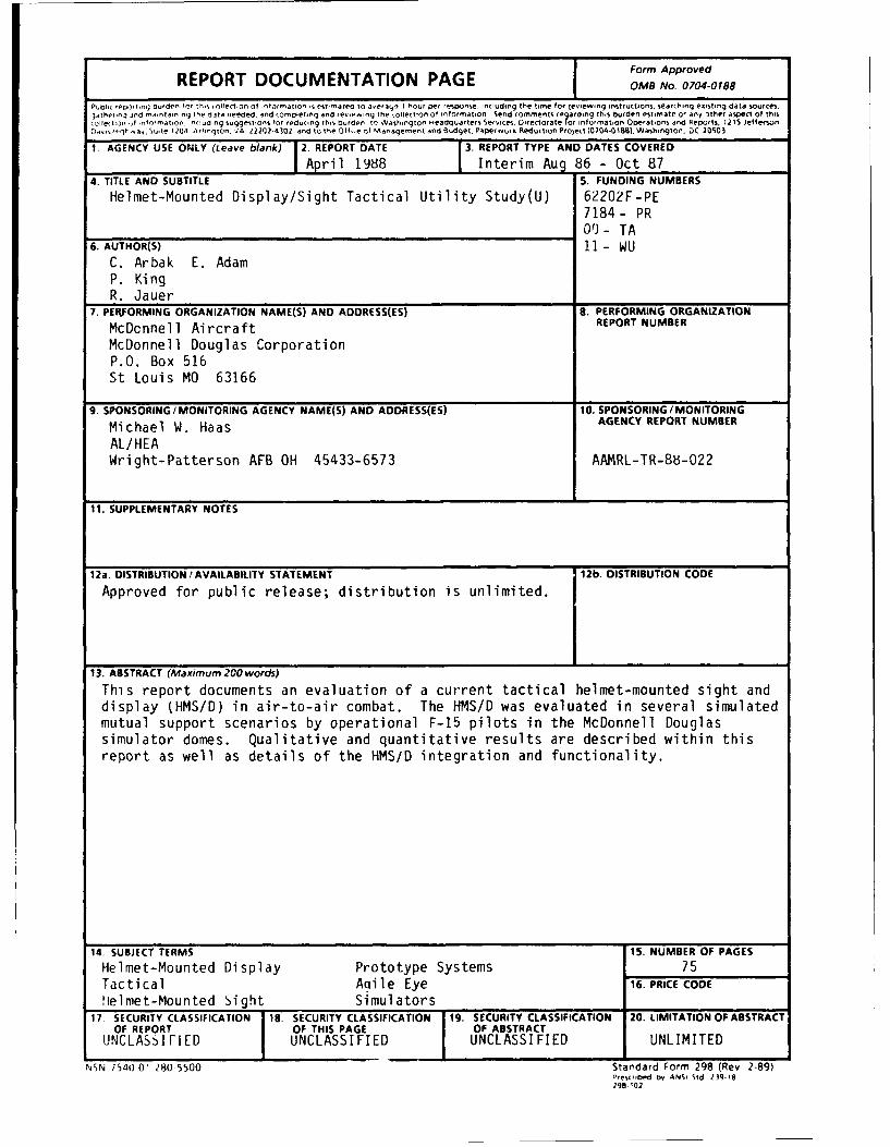
This report documents an evaluation of a current tactical helmet-mounted sight anddisplay (HMS/D) in air-to-air combat. The HMS/D was evaluated in several simulatedmutual support scenarios by operational F-15 pilots in the McDonnell Douglassimulator domes. Qualitative and quantitative results are described within thisreport as well as details of the HMS/D integration and functionality.
14. SUBJECT TERMS 15. NUMBER OF PAGESHelmet-Mounted Display Prototype Systems 75Tactical Aoile Eye 16. PRICE CODE
H1elmet-Mounted Sight simulators_____
17. SECURITY CLASSIFICATION 18. SECURITY CLASSIFICATION 19. SECURITY CLASSIFICATION 20. LIMITATION OF ABSTRACT
UNLSIIDUNCLASSIFIED UNCLASSIFIED UNLIMITED
NSN 754f)O1 280-5500 Standard Form 298 (Rev 2-89)Prescribed by ANSI Sid 139 i18298-t02

GENERAL INSTRUCTIONS FOR COMPLETING SF 298
The Report Documentation Page (RDP) is used in announcing and cataloging reports. It is importantthat this information be consistent with the rest of the report, particularly the cover and title page.Instructions for filling in each block of the form follow It is important to stay within the lines to meetoptical scanning requirements.
Block 1. Agency Use Only (Leave blank). Block 12a. Distribution/Availability Statement.Denotes public availability or limitations. Cite any
Block 2. Report Date. Full publication date availability to the public. Enter additionalincluding day, month, and year, if available (e.g. 1 limitations or special markings in all capitals (e.g.Jan 88). Must cite at least the year. NOFORN, REL, ITAR).
Block 3. Type of Report and Dates Covered. DOD See DoDD 5230.24, "DistributionState whether report is interim, final, etc. If S e e o n Technicalapplicable, enter inclusive report dates (e.g. 10 Documents. "Jun 87 - 30 Jun 88). DOE See authorities.
Block 4. Title and Subtitle. A title is taken from NASA - See Handbook NHB 2200ime part of the report that provides the most NTIS - Leave blank.meaningful and complete information. When areport is prepared in more than one volume, Block 12b. Distribution Code.repeat the primary title, add volume number, andinclude subtitle for the specific volume. Onclassified documents enter the title classification DOD - Eae blank.in parentheses. DOE -Enter DOE distribution categories
from the Standard Distribution for
Block 5. Funding Numbers. To include contract Unclassified Scientific and Technical
and grant numbers; may include program Reports.element number(s), project number(s), task NASA - Leave blank.number(s), and work unit number(s). Use the NTIS - Leave blank.
following labels:
C - Contract PR - Pruject Block 13. Abstract. Include a brief (MaximumG Grant TA - Task 200 words) factual summary of the mostPE - Program WU - Work Unit significant information contained in the report.
Element Accession No.
Block 6. Author(s). Name(s) of person(s) Block 14. Subiect Terms. Keywords or phrasesresponsible for writing the report, performing identifying major subjects in the report.the research, or credited with the content of thereport. If editor or compiler, this should followthe name(s). Block 15. Number of Pages. Enter the total
number of pages.Block 7. Performing Organization Name(s) andAddress(es). Self-explanatory. Block 16. Price Code. Enter appropriate price
Block 8. Performing Organization Report code (NTIS only).Number. Enter the unique alphanumeric reportnumber(s) assigned by the organizationperforming the report. Blocks 17.- 19. Security Classifications. Self-
explanatory. Enter U.S. Security Classification in
Block 9. Sponsoring/Monitoring Agency Name(s) accordance with U.S. Security Regulations (i.e.,and Address(es). Self-explanatory. UNCLASSIFIED). If form contains classified
information, stamp classification on the top andBlock 10. Sponsoring/Monitoring Agency bottom of the page.Report Number. (If known)
Block 11. Supplementary Notes. Enter Block 20. Limitation of Abstract. This block mustinformation not included elsewhere such as: be completed to assign a limitation to thePrepared in cooperation with...; Trans. of...; To be abstract. Enter either UL (unlimited) or SAR (samepublished in.... When a report is revised, include as report). An entry in this block is necessary ifa statement whether the new report supersedes the abstract is to be limited. If blank, the abstractor supplements the older report. is assumed to be unlimited.
Standard Form 298 Back (Rev 2-89)

PREFACE
The work reported on herein was performed under Contract Number F33615-85-D-0514, Task 0013. This report, entitled "Helmet Mounted Display/ Sight TacticalUtility Study," covers the period August 1986 through October 1987 and thetechnical efforts concerning tactical applications of Helmet Mounted Display/Sight. The portions of Task 0013 that concern strategic applications aredocumented in a separate technical report.
The impetus of this effort was a message written by the Fighter RequirementsDivision (TAC/DR) located at Tactical Air Command Headquarters requesting a studyto be pursued to evaluate the tactical utility of current HMD/S systems integratedinto F-15 aircraft performing air-to-air combat. To support this request, theHuman Engineering Division developed a strategy to qualitatively and quantitativelyevaluate HMD/S utility in as operational a setting as possible. This strategyinvolved utilizing manned simulation as a tool to support operational scenariosand threat mixes. This permitted operational F-15 pilots to combine the HMD/Scapability with the current weapon deployment concepts and tactics. This strategyallowed maximum flexibility and variability in use of aircraft and HMD/S capability.
The following members of the Technical Staff of the Advanced Design group atthe McDonnell Aircraft Company participated in this effort; P. King, C. Arbak, B.Waldron, R. Jauer, and E. Adam.
This task was conducted for the Armstrong Aerospace Medical Research Laboratorythrough the Southeastern Center for Electrical Engineering Education by McDonnellDouglas Corporation and Washington University under the technical direction ofMr. Michael Haas and Dr. John Pellosie. Other Air Force Agencies, such as theTactical Air Command, provided invaluable consultation regarding operationalconsiderations and mission scenario design. Lt. Col. Michael Gentrup (HQ/TAC/DRFA)and Lt. Col. Joe Farcht (ASD/TACSO) worked closely with AAMRL providing operationaldirection in the conceptual phase of the effort as well as '.ring its period ofperformance and were instrumental in assuring its successful completion.
Accesion For
Ud i.O:j. :ed I
e~p),
Di t ib-Aio.il
Avdildbiliy Cc ;!s
Drit Sp..ciai
Al
TABLE OF CONTENTS
SECTION TITLE PAGE
PREFACE.................. . . ..... . . . .. .. .. .. ......TABLE OF CONTENTS............. . . .... .. .. .. . ...LIST OF FIGURES............ . ... . ... .. .. .. . .....
1.0 INTRODUCTION............. . ... . .... .. .. .. . .....
2.0 SUMMARY. .. ...... ......... ............ 2-1
3.0 CREW STATIONS .. ... ......... ......... ... 3-1
3.1 F-15C CREW STATIONS .. ....... ............ 3-13.2 CHANGES TO F-15C MSIP SYSTEM .. ... ............ 3-13.3 F-15E CREW STATION...... ... . . ... .. .. .. ..3.4 AGILE EYE HELMET MOUNTED DISPLAYS AND INTEGRATION . . . 3-63.5 MICS CREW STATIONS .. ... ......... ....... 3-13
4.0 TEST DESCRIPTION. ... ......... ............ 4-1
4.1 TEST EQUIPMENT. .. ...... ......... ..... 4-14.2 PILOT PARTICIPANTS. .. ...... ......... ... 4-34.3 PROCEDURE. ... ......... ......... ... 4-34.4 TEST SCENARIOS. ... ..... ......... ..... 4-64.5 RULES OF ENGAGEMENT (ROE) .. ........ ....... 4-10
5.0 RESULTS. .. ...... ......... ............ 5-1
5.1 VARIABLES EVALUATED .. ....... ............ 5-15.2 ANALYSIS OF HMS/D QUANTATIVE DATA .. ....... .... 5-25.3 QUALITATIVE DATA SUMMARY. .. ....... ........ 5-18
6.0 CONCLUSIONS AND RECOMMENDATIONS .. ... ......... ... 6-1
7.0 LIST OF ABBREVIATIONS. .. ...... ......... .... 7-1
APPENDIX A HELMET MOUNTED DISPLAY FORMATS. .... ......... ... A-i

LIST OF FIGURES
FIGURE TITLE PAGE
1-1 "Agile Eye" Weight ............................ ..... 1-21-2 "Agile Eye" C.G. Comparison ....... ............... 1-2
3-1 Stick Switch Functions .............................. 3-13-2 HMD Auto Acquisition Switch Functions . .......... .... 3-23-3 Throttle Switchology ........ ................... 3-33-4 F-15E Forward Crew Station Main Instrument Panel ..... 3-43-5 HUD Controls ...... ....................... .... 3-53-6 Multipurpose Display Controls ... .............. .... 3-63-7 F-15C MSIP Stick Grip and Throttle Controls ....... ... 3-73-8 "Agile Eye" Helmet System ...... .. ................ 3-83-9 HMS/D Control Panel .... ... .. ................... 3-103-10 Data Parameters Passed Between the F-15 Avionics and the
Agile Eye ...... ........................ .... 3-113-11 Component Interconnects for the Agile Eye Flight Test
Prototype System ...... .................... .... 3-123-12 Agile Eye Connection to F-15 Avionics System ... ....... 3-133-13 MICS Components ..... ..................... ..... 3-14
4-1 Agile Eye Interaction ..... .................. ..... 4-24-2 Week One Schedules and Order of Initial Conditions .... 4-54-3 Week Two Schedules and Order of Initial Conditions .... 4-54-4 Air Base Defense Setup ... .................. 4-64-5 Typical Initial Conditions Air Base Defense Scenario. 4-74-6 Fighter Sweep Setup ...... ... ................... 4-74-7 Typical Initial Conditions Fighter Sweep Scenario .... 4-84-8 IvivIvi Setup ...... .... ...................... 4-94-9 2v2 Setup ....... ........................ ..... 4-9
5-1 Variables Analyzed ..... .................... 5-15-2 Analysis of Variance Summary Table for Blue Kills . .. 5-35-3 Average Kills Per Run for Blue Aircraft . ......... ... 5-45-4 Analysis of Variance Summary Table for Red Kills ..... 5-45-5 Average Kills Per Run for Red Aircraft ................. 5-55-6 Analysis of Variance Summary Table for F-15 Pilot
Work Load ................................. ..... 5-55-7 Average Blue Workload ..... .................. ..... 5-65-8 Analysis of Variance Summary Table for Red Pilot
Work Load ...... ........................ ..... 5-65-9 Average Red Pilot SWAT Score ... ............... ..... 5-75-10 Analysis of Variance Summary Table For Percentage of
Time Outside the HUD ..... .................. ..... 5-75-11 Percentage of Time Pilot LOS Was Outside the HUD ..... 5-85-12 Analysis of Variance Summary Table for Helmet Line of
Sight More Than 450 Outside the HUD ..... ........... 5-85-13 Percent of Time Pilot LOS Was More Than 45 Degrees OFF
Boresight ...... ........................ ..... 5-95-14 Analysis of Variance Summary Table for Designations of
Targets Outside the HUD ........ ................. 5-9
iii

LIST OF FIGURES (Continued)
FIGURE TITLE PAGE
5-15 Number of Supersearch Designations Outside HUD ...... ... 5-105-16 Analysis of Variance Summary Table for Designations of
Targets Outside the HUD While in Boresight Mode ..... 5-105-17 Number of Boresight Mode Designations Out of HUD ..... 5-115-18 Analysis of Variance Summary Table for Variance Summary 5-115-19 AIM-9 Launches ................................. 5-125-20 Analysis of Variance Summary Table for AIM-9 Kills
by Blue ............................................. 5-125-21 Average AIM-9 Kills Per Run ... ............... .... 5-135-22 Analysis of Variance Summary Table For Range of
First Launch .................................. .... 5-135-23 Average Time From Start of Run to First Launch ...... ... 5-145-24 Analysis of Variance Summary Table for Time of
First Launch ...... .. ...................... .... 5-145-25 Range at First Launch ...... .................. .... 5-155-26 Exchange Ratios for Each Week of Data Collection ..... 5-165-27 Correlation Matrix for Visual Engagement With HMD Off 5-175-28 Correlation Matrix for Visual Engagement With HMD On . 5-17
6-1 Exchange Ratio Results ..... .................. .... 6-16-2 Red and Blue SWAT Scores .... ................. ..... 6-2
A-i Missile Shoot Cue for Tracked Target ............. .... A-IA-2 AIM-9 L/M Sidewinder Displays ... .............. ... A-2A-3 Breakaway "X" ........ .. .................... ..... A-3A-4 AAI Reply Modes ...... .... ..................... A-4A-5 Basic HMD Symbols ................................ .... A-5A-6 Display-Limited Horizon Bar ... ............... .... A-6A-7 Helmet Automatic Acquisition Modes .. ............ .... A-7A-8 Helmet Automatic Acquisition Display When Radar Antenna
is at Gimbal Limits ..... ................... ..... A-8A-9 STT/RAM Display ...... ..................... ..... A-9A-10 TWS Displays ....... ....................... ..... A-1OA-li Typical Symbols Reject Display .... .............. .... A-i
iv

1.0 INTRODUCTION
Visually coupled systems, under development at the Armstrong AerospaceMedical Research Laboratory (AAMRL) since 1966, have been advocated for use inhigh performance fighters. Helmet mounted sight/displays (HMS/D) are considereda prime method for enhancing pilot capabilities, especially in acquiring andmaintaining "situation awareness," and the large off-boresight capabilitypromises to provide improved combat effectiveness.
The VCSS (Visually Coupled System Simulation)-Vista Sabre Study was afunded program at MCAIR from the Southeastern Center for Electrical EngineeringEducation (SCEEE). An objective of VCSS was to demonstrate the capabilities andbenefits of a helmet mounted sight and display (HMS/D) to Tactical Air Command(TAC) pilots.
The purpose of this MCAIR report is to analyze the data generated by theVCSS study, draw conclusions and recommend further investigations of HMS/Dsystems.
The purpose of the VCSS study was to help the Air Force and industrydevelop displays and cockpits that help reduce workload, and increase situationawareness and system effectiveness. A man-in-the-loop simulation was used tocollect data on equipment and concepts that have been developed.
The simulation objectives were to:
1) Demonstrate possible applications of an HMS/D to a TAC air-to-airmission.
2) Collect subjective workload data.
3) Determine a better way to integrate an HMS/D into an F-15.
4) Determine other applications of an HMS/D to TAC Missions.
Two F-15 cockpits were used for the "Blue" cockpits. One is an F-15C MSIP(multi-staged improvement program) cockpit. The other is an F-15E cockpit thatwas modified to respond as if it was an F-15C MSIP cockpit.
Two MICS (manned interactive control stations) were used for the "Red"cockpits.
The HMS/D used was the Agile Eye made by Kaiser Electronics. The Agile Eyeis a new helmet design that incorporates the latest technology available to allfunctions of a flight helmet. It weighs only 2.6 lbs, or one-half pound lighterthan the current lightweight helmet (Figure 1-1). It has a center-of-gravity(cg) that is near the cg of the pilot's head (Figure 1-2). The cg of currenthelmets is forward of the head cg which induces extra load on the pilot's neckduring ejection. The aerodynamic design of Agile Eye reduces aero loads from 600lbs with current helmets, in a 500 Kt ejection, to only 300 lbs.
1-I

344
0 87 20
2 63 1S58 ' 0 2
U 209N 2
S 7/,
Navy Air Force KaiserHGU-33P HGU-55P Agile Eyc
Figure 1-1. "Agile Eye" WeightGP3OO-8
0.G. of Standard Helmet
C.G. of Head
S C.G. of Kaiser'sH "Agile Eye'
Point
Figure 1-2. "Agile Eye" C.G. Comparison
Proficier-y ising the HMS/D and flying in the simulator was developed witha combination uf classroom briefings, study, and with trials, discussions andpractice sessions in the simulator. During the experiments, normal crew tasks,such as flying, communicating, operating sensors (e.g., radar), responding tothreacs, acquiring targets, and launching weapons were performed. Debriefing wasic,omplished with questionnaires and interviews.
Two blue force pilots in F-15 simulators conducted 2v2, 2v4 and 2v8air-to-air missions against digital opponents and two Aggressor pilots flyingmanned interiztive combat stations (MICS). The HMS/D was used by the F-15 pilotto provide off boresight target acquisition, direct target detection and trackingwith the radar and employee weapons.
The effectiveness of the HMS/D was evaluated by comparing identicalmissions conducted with and without the HMS/D. Performance data were collectedon sensor employment, weapon usage, and exchange ratios in addition to subjectiveworkload and opinion data. Data were recorded on a master data tape and printedoff-line. Audio and video tape records of all missions were kept.
HMS/Display formats were jointly defined by MCAIR and AAMRL. MCAIR useddisplay symbology and integration in concepts from the F-15C so that a minimumchange was made to the basic system operation. Helmet display symbology wasdeveloped at MCAIR and evaluated at AAMRL prior to the full mission evaluation.
F-15C aerodynamics models were used along with integrated controls anddisplays.
13

2.0 SUMMARY
Two Agile Eye prototype helmet mounted sight and display (HMS/D) systemswere evaluated with 30 hours of testing in two simulated F-15C MSIP aircraft inMCAIR's flight simulation facility. The test lasted two weeks. Each week hadtwo TAC F-15 pilots fly with and without helmets in four test scenarios (2v2,2v4, 2v8 and IvivivI). Opposing the F-15s were a variety of aircraft. Two ofthe opponents were flown by Aggressor pilots from Nellis AFB. The otheropponents were digital aircraft "flown" by the sinulation computer.
The HMS/D concept was highly lauded by the pilots. They also noted someimprovements needed for the prototype systems that they used for the test. Theseincluded better visor optics, a better/firmer fit, and a sharper focus of thedisplay optics.
The measured data showed an initial slight decrease in performance whilethe pilots learned how to use the new capability. That was followed by a largeincrease in performance at the end of the testing period when the exchange rationearly doubled while it remained nearly constant without the HMS/D.
The pilot opinion data also strongly supported the HMS/D for thewithin-visual range (WVR) arena. The pilots were especially enthused about thetime saved with the HMS/D, the capability it gave them to launch AIM-9 missileswhile guiding an AIM-7 and the capability to launch AIM-9 missiles while keepingbasic fighter maneuvering (BFM).
2-.

3.0 CREW STATIONS
An F-15C MSIP and an F-15E cockpit were used for the simulations. lheF-15E was modified to function like an F-15C MSIP.
3.1 F-15C CREW STATIONS
The baseline aircraft was an F-15 with MSIP equipment, and operationalflight program 1002 in the central computer and a CAJ radar tape. The Radarpossessed trdck-whilV-scan (TWS) and raid assessment mode (RAM) capabilities.
3.2 CHANGES TO F-15C MSIP SYSTEMS
The following changes were made to the operation of the uz .sine aircraft:
o The forward and aft positions of the auto acquisitivn switch on thestick were redefined when the radar was in a search mode. Theforward position of the switch provided helmet automatic acquisition;the aft position had no function. The switch is shown in Figure 3-1.
Castle Switch(Not Used) -Ti Switch
Weapon Release /Switch--
Trigger Acquisitionand TWS Switch(See Table 5-1)
AIM-9L/M SeekerUncage
HMD Boresight
Automatic FlightControl Disengage -GP7"-201-3-A
Figure 3-1. Stick Switch Functions
o The Supersearch, Boresight, and Vertical Scan auto acquisition modeswere replaced by two helmet auto acquisition modes: HelmetSupersearch (HSS) and Helmet Boresight (HBST). Auto Gun Scan was
3-1

still available as a third auto acquisition mode and operated in thesame manner as on the MSIP F-15.
o The HUD Symbols Reject switch also removed symbols from the HelmetDisplay.
o The operation of the AIM-9 L/M seeker when not slaved to the radarwas changed. Basically, all operations that previously resulted inslaving ti.e seeker to aircraft boresight in the MSIP F-15 had theeffect of slaving the seeker to the helmet line of sight (LOS).
o Certain symbols were removed from the HUD when the HMD was in use toeliminate clutter (see Appendix A).
All other aircraft systems and displays of the baseline aircraft wereunchanged and operated in the manner defined in T.O. IF-34C-1-1, Non-NuclearWeapon Delivery Manual (Air-to-Air). This included operation of the autoacquisition switch with the radar in a track mode to obtain TWS or RAM modes.
3.2.1 Flight Control Stick - The HMD Auto Acquisition Switch Functions aredepicted in Figures 3-1 and 3-2. Note that a castle switch was located where thetrim switch is on F-15A and C models. For this simulation the castle switch wasinoperative. The trim switch was located to the right of the castle switch.
Auto Acquisition Radar Mode
Switch Position Search STT
Forward 1 = HMD Supersearch 1 = HD.TWS2 = HMD Boresight 2 = STT
Aft No Function 1 = TWS2 = STT
Down Return to Search Return to Search
Note: If press/release TOC and FORWARD within 2 sec, then: QP7M201-"1= RAM2=STT
Figure 3-2. HMD Auto Acquisition Switch Functions
3.2.2 Throttles - The switch functions on the throttles are depicted inFigure 3-3. Note the reticle stiffen and SRM reject switch locations werechanged. The IFF interrogate button was a four-position switch with TWE prioritytarget step, IFF interrogate, AIM-9 boresight/gun reticule stiffen and EWWSfunctions.
3"2

MicrophoneRaaAneaSwitch Elevation ntrol
Speed BrakeSwitch 2 B -
/66Target eRear Fwdesigt
Not nngUsed Reject4
s et P rt
TagStep
0 P73.0201-2-N
Figure 3-3. Throttles Switchology
3.3 F-15E CREW STATION
In the VCSS simulation the F-15E was configured for aerial combat withradar and heat-seeking air-to-air missiles and a 20 mm gun. For the purpose ofthis simulation the F-15E VCSS crew station reflected the Multi Stage ImprovementProgram (MSIP) F-15C capabilities.
The forward crew station is depicted in Figure 3-4. Stick and throttleswitchology were the same as the MSIP F-15C described earlier. VCSS HUDsymbology was the same as the standard F-15 HUD. Radar symbols were presented on
the left Multi Purpose Display (MPD) and TEWS symbols on the right MPD. Thecenter color display displayed weapons data (simulated PACS display).
33

1920o
18317.
16
14 . .. 25
3 ,Wrnn Tone.Sil nce Sele--Swit26124P 1 Rear View Mirro13
) =' 28
8 _ -30
7 V I 22 C-artLi3g
A&' 33
8E rn Jtsa 3 .Cn Pt 34
-' "- - -- --- '36
2t Al l 3 7
42"-, '"41 38
I Landing Gear Handle 24 H3
2. Ptch Ratio Select Sw2tch and indarator3 Warning Tone Silence Select SwStch4 Landing Gear Position Lights 19. Rear View Mirror
5 Armament Control Panel 20 Lock/Shoot Cauton Lights
6 Angle-of-Attack IndMcator 21. Air Refueling Ready L3gcit
7 Vertical Velocoty indicator 22. Clart Light8 Emergency Jettison Select Switch 23. Standby Compass 34. Cabin Pressure Ali meter9. Standby Airspeed Indicator 24, Head Up Display Combiner 35 Engine Monitor Display
16 Standby Alttiude Indicator 25 Head Up Display Camera Perscope 36 Jet Fuel Starter Handle
11 Standby Altimeter 26 Warning Loght Panel 37 Holding Brake Select Switch12 Fire Warning/ Extinguishing Control Panel 27 Up-Front Control 38 Flight Control Stick Grip
13 Monochromatic Multipurpose Display 28. Advisory Light Panel 39 Left Circuit Breaker Panel
14 Multipurpose Color Display 29 Utilty Hydraulic Pressure Indicator 40, ECS Variable Discharge Louver
15. Master Mode Select Switches 30. Primary Hydraulic Pressure Indicator41, Right Circuit Breaker Panel
16 Head Up Display Control Panel 31 Data Transfer Module Receptacle 42 Top Circuit Breaker Panel
17 Emission Limit Caution Light 32 Analog Clock 43. Emergency Brake Steering Control
18 Master Caution Light 33 uel Quantity Indicator 44 Rudder Petal Adlustment Control
G0P73-0201 .1-
Figure 3.4. F.15E Forward Crew Station Main Instrument Panel
3.4

3.3.1 HUD Controls - The HUD controls were located directly below the UFC,see Figure 3-5. Power ON/OFF and symbol brightness were controlled by the farleft knob. For this simulation the two knobs on the right were not used. Thetoggle switch on the left controlled symbol declutter.
HUD
6 ,-
IEE -% - - - - -.. -
-I .. .. ..E .
HUD Control Panel
GP73-0201-4S-A
Figure 3-5. HUD Controls
3.3.2 MultipurDose Display Controls - Each of the three multipurposedisplays had an "ON/OFF" toggle switch in the upper right corner. Brightness andContrast rocker switches were in the lower left and right corners, respectively,see Figure 3-6.
3-5

I @ ON Power
6 I OFF
B n @.I
IV
Brigtns aR ii Z L l CONT @I - Contrast
G34201M4&R
Figure 3.6. Multipurpose Display Controls
3.4 AGILE Eye Helmet Mounted Displays and Integration
This section provides a brief description of the Kaiser Agile Eye system,the controls required to operate it, and the changes made to integrate the helmetmounted display (HMD) into the F-15C avionics. The following summarizes thesechanges:
0 The forward and aft positions of the auto acquisition switch wereredefined when the radar was in a search mode. The forward positionof the switch provided Helmet Automatic Acquisition; the aft positionhad no assigned function.
0 The Supersearch, Boresight, and Vertical Scan auto acquisition modeswere replaced by two helmet auto acquisition modes--Helmet Super-search (HSS) and Helmet Boresight (HBST). Auto Gun Scan wasavailable as a third auto acquisition mode and operates with nochanges.
o Operation of the AIM-9 L/M seeker (when not slaved to the radar) waschanged. All operations that previously slaved the seeker toaircraft boresight slaved the seeker to the helmet line of sight(LOS).
o The HUD Symbol Reject switch controlled both HUD and HMD formats.
0 Certain symbols were removed from the HUD when the HMD was in use.
3-6

The F-15C MSIP stick grip and throttle control switches were as shown inFigure 3-7. Those used during operation of the HMD are indicated and areaddressed in subsequent paragraphs. All other stick and throttle switches wereunchanged in their operation.
Weapons Release(All Except Gun)
SwitchesUsed
Auto Acquisition Switch (Four Position2
AIM-9 Seeker uncage and HMD Boresight
MicrophoneRadar Antenna
BrakeSwitch=- 2 HMD Blankn
3-3
~Target
Designalion6 Control
5Inboard Forward Up
NCTot I bo r * Outb,,ard interrogate
used ejectAIM-9L/M
Boresight /i Gunsight
Staten
DownGP?3.0201-2S-A
Figure 3-7. F-15C MSIP Stick Grip and Throttle Controls
3- 7

3.4.1 Kaiser Agile Eye System - The Agile Eye helmet mounted display (HMD)systems used for this test were prototype versions to evaluate the concept ofhelmet mounted displays. Because they were prototypes, some aspects were lessthan ideal. Participants in the evaluation were asked to share their opinions onboth good and bad points of this system. A summary of these comments is reportedin the results section.
The Agile Eye system is composed of three major subsystems: the helmetitself, the head tracker and the display system which consists of a displayprocessor and a display driver unit (DD). These are illustrated in Figure 3-8and described briefly below.
Helmet Subsystem Tracker SubsystemKaiser MDEC/Polhemus
SourceSensor
-
DriverTracker,r lv Electronics
Prcessor Il
Total system weight - 30 11)
Figure 3-8. "Agile Eye" Helmet System
Agile Eye Helmet - The Agile Eye helmet was designed as a completely newflight helmet with a display integrated into the helmet. This avoids problemsthat previous helmet display systems have incurred by adding display elements toa standard flight helmet. The add-on approach has led to visibility, weight, andcenter of gravity (CG) problems which made the helmet undesirable (or evenunacceptable) for use in flight.
3-8

The new design also improved three basic characteristics over the presentUSAF light weight flight helment. The amount of aerodynamic lift produced bythis helmet at high speed was cut in half. The weight was redistributed so thatthe overall CG of this helmet was closer to the natural CG of the human head thanpresent helmets. The total weight (i.e., with tracker and display elements) wasone-half pound lighter. This was done by using new components and Kevlar for theshell which provided the strength required for a flight helmet, but greatlyreduced the weight.
Head Tracker - The Agile Eye system employs an electromagnetic trackingsystem manufactured by Polhemus Navigation Sciences, a subsidiary of McDonnellDouglas Electronics Company. A source, positioned above the pilot's head in thecockpit, radiates three orthogonal magnetic signals. In the simulator, thesource was mounted on an arm attached to the ejection seat. In an aircraft, itcould be mounted anywhere as long as it has a clear line of sight to the helmet.
The receiver was mounted in the top of the Agile Eye helmet. Changes inthe orientation of the helmet relative to the source cause changes in thereceived signal. By comparing the transmitted and received signals, helmetposition and orientation are determined. From these, line of sight (LOS) anglesare om,-.ted. T,6 display is then tailored for the LOS. Accuracy was notmeasured as part of this test. However, subjective assessment of the conceptindicated that one-half degree would be sufficient for most flight operations.This is within the accuracy reported for the system when it has been properlyinstalled and calibrated.
Helmet Display System - The display was provided by a half-inch diametercathode ray tube (CRT), mounted inside the helmet on the right. The CRT imagewas transported to the helmet visor using fiber optics and mirrors. The visorwas the final optical element and acted as the combining glass for the display,superimposing the display elements on the outside visual scene. This systemproduced a 12 degree field of view (FOV) display positioned at any LOS that thepilot could achieve through head movements.
The video signal for the helmet CRT was generated by a digital graphicsprocessor. This signal is transmitted to the helmet at a low voltage level sothat no spark would be produced by quick disconnect of the necessary electricallines. A high voltage power supply was located within the helmet and convertedthe input video signal to the voltage levels necessary to drive the helmet CRT.
3.4.2 HMD Controls and Integration - The control panel for the HMS/D isshown in Figure 3-9. The only item used during the test was the brightnesscontrol which was set at the start of a session.
3"9

R11 D1 BRS fAvATBY ; CL2 T/S A/OI GDAY NGT
SRGHTNESS
/-\
ON
POWER
j @OFF
Figure 3-9. HMS/D Control Panel
The HMS/D was integrated with the F-15 so that there was a minimum chargein operational procedures for the pilots. A boresight procedure was added toensure that the helmet sight was aligned with other aircraft systems.
The display formats used in this evaluation are summarized in Appendix A.
3.4.3 Compatibility With F-15 Avionics - The Agile Eye system can beeasily integrated with the F-15 avionics. The prototype is currently configuredto talk on a 1553A Bus. This military standard bus is available on post-MSIP(multi-staged improvement program) F-15s. The interface could be changed to workjust as well with the H009 Bus which is on all F-15s.
The message traffic imposed on the bus is approximately 37 words. Thesepass data such as listed in Figure 3-10 between the central computer and thedisplay processor tracker (DPT) at a 20 Hz rate.
3-10

" Display Symbol On/Off Flags
" Line-of-Sight Angles for Radar or Other Sensors and Corresponding Symbology(Display Two Simultaneously)
* Aircraft Parameters- Pitch/Pitch Rate - Mach- Roll/Roll Rate - Acceleration (Normal)- Heading - Airspeed- Yaw Rate - Altitude- Angle-of-Attack
" Message Window Locations and Alphanumerics in Each Window
" Helmet Parameters- Pitch - Line-of-Sight- Roll - Mode- Heading
GP84-0078,13-T
Figure 3-10. Data Parameters Passed Between the F-15 Avionics
and the Agile Eye DPT
The DPT is the interface to the Agile Eye through its mux bus connection asseen in Figure 3-11. The DDU (display driver unit) is mounted in the cockpitnext to the standard existing communications and oxygen connectors which continueto serve their current functions. The display functions are implemented bypluging the umbilical cord quick disconnect into the DDU.
3-11

Magnetic FieldCoupling
HelmetMounted
Display StandardExisting~CockpitConnectors
DisplayProcessorTracker (DPT-Mounted inAvionics Bay) Oxygen
' Communications
AircraftPower-_
Supplies- Ni" AC
* DC Display Driver Unit tDDU-" DC Mounted on Cockpit Console)
AircraftMUX Bus GP83o07827
Figure 3-11. Component Interconnects for the Agile EyeFlight Test Prototype System
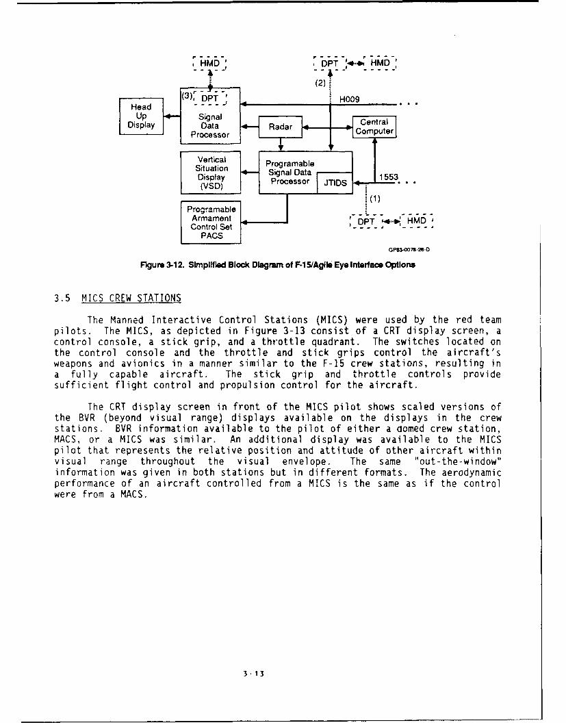
There are several possibilities for connecting to the F-15 avionics systemas shown in Figure 3-12. The first is to use the 1553 Bus, if available on the
aircraft, and the existing design of the OPT. The second is to redesign the DPTbus interface to work with the H009 Bus. The third is to redesign the DPT andthe signal data processor (SDP) to be collocated and interface with the H009.With redesign of the SOP, better than 50 percent of the volume could be freed.There are 16 cards now in the SOP. These could be reduced to seven with today's
technology and drive a stroke only HUD. The vacated card slots would probablyprovide sufficient volume for a redesigned OPT.
3-12
HMD DPT 4.. HMD'
(3Ir)o DPTr' ~ H009
Head -----Up Signal 1Central
Display 1 iData Radar ComputerS Processor
Vertical 3 M P rOg ra ab leSituation Sins (ebdDpirsisplay scr , 1553wepnVad) mProcessor -IDS c s
Programable s groArmament PHM
Control Set a i rr a.PACS
GPS3-O078-26-0
Figure 3-12. Simplified Block Dagram of F-1 5/AgIlo Eye Interfase Optvons
3.5 MICS CREW STATIONS
The Manned Interactive Control Stations (MICS) were used by the red teampilots. The MICS, as depicted in Figure 3-13 consist of a CRT display screen, acontrol console, a stick grip, and a throttle quadrant. The switches located onthe control console and the throttle and stick grips control the aircraft'sweapons and avionics in a manner similar to the F-15 crew stations, resulting ina fully capable aircraft. The stick grip and throttle controls providesufficient flight control and propulsion control for the aircraft.
The CRT display screen in front of the MICS pilot shows scaled versions ofthe BVR (beyond visual range) displays available on the displays in the crewstations. BVR information available to the pilot of either a domed crew station,MACS, or a MICS was similar. An additional display was available to the MICSpilot that represents the relative position and attitude of other aircraft withinvisual range throughout the visual envelope. The same "out-the-window"information was given in both stations but in different formats. The aerodynamicperformance of an aircraft controlled from a MICS is the same as if the controlwere from a MACS.
3 -!13

FigUre 3-13. MICS Components

4.0 TEST DESCRIPTION
The purpose of the simulation was to demonstrate and measure the utility ofa HMS/D in air-to-air combat. Four operational, F-15 C/D, TAC pilots and fourAgressor pilots flew the missions along with digital aircraft embedded in thesimulation. Two F-15 and two agressor pilots flew simultaneously in one week oftesting. This was followed by a second week of testing with the other fourpilots.
The objective of this test was to demonstrate and evaluate the utility of ahelmet mounted display (HMD) in air combat. This was accomplished by simulatingvarious air combat situations, collecting pilot comments, and comparing resultswhen pilots have the HMD ("Helmet On") with results in a conventional cockpit("Helmet Off"). The test scenarios included enemy fighters, enemy bombers, andfriendly aircraft. Both offensive and defensive missions were examined. Theenemy fighters were both digital and manned by "agressor pilots" flying fromMICSs.
During the test, multiple runs up to 15 minutes each were performed. Eachrun had a different set of initial conditions; i.e., the other aircraft differedin type, starting position, and total numbers. Each set of initial conditionswas used twice - once with the HMD off, and once with the HMD on--as much aspractical. Scheduling limitations prevented collecting a full factorial set ofdata.
When the HMD was off, the simulators functioned as normal F-15C MSIPaircraft. When the HMD was on, the systems were changed to the integrated HMD/Sconfiguration.
The basic tasks of the F-15 pilots during the test we. to operate as aflight, destroy enemy aircraft, avoid attacking friendly aircraft, andsuccessfully defend against enemy attacks. Toward this end, they were instructedto employ standard USAF two-ship air combat tactics.
Subjective workload data were collected from both F-15 and Agressor pilots.Objective data collected included kills and weapons employment data. Theexperimental design described provided maximum, control of learning and practiceeffects within the constraints of time and numbers of missions.
4.1 TEST EQUIPMENT
The test was performed in McDonnell Aircraft Company's Manned Air CombatSimulators (MACS). MACS-IV, which is configured as an F-15C, and MACS-V, whichis configured as an F-15E were used. The F-15E cockpit was programmed so thatthe basic avionics operated as an F-15C. Plthough the cockpit appearance isdifferent, the left CRT was used to display the F-15 VSD and the right CRT forthe TEWS display. The stick and throttle switches were identical in bothcockpits and provided F-15C functions.
Each cockpit is built on a platfc.'m that sits in the middle of a 40 footdiameter sphere, or "dome". During operation, computer graphics are used toproject ground, sky, and other aircraft onto the surface of the dome. Thisprovides full vision capabilities to the pilot in addition to the cockpitdisplays. The overall visual effect might give a sensation of motion; however,the cockpit and platform are stationary.
4-1

The following limitations were present during this test. First, the amountof navigation that could be performed was limited. The Dynamic Earth/Sky systemwas used to provide the out-the-window background visual scene. This s):temprovides a horizon and a generic ground pattern. It provides excellent cues forBFM (Basic Fighter Maneuvering), but cannot be used to navigate. The TACAN orINS systems were not simualted. However, Nav destinations were displayed on theVSD display. Four destinations (B, 1, 2, and 3) were programmed for use duringthe test to provide indications of FEBA location and the position of theairfield. Their locations are shown in the figures describing Test Scenarios.
The targets were not displayed until they were within 2.5 NM of anaircraft. Therefore, the best eyes in the world did not appreciably help visualcontact. While fighting, if a pilot exceeded 4 Gs for 30 seconds, he experienced"grayout" as the entire dome was turned off. A sliding scale of time ,s. Gscaused the grayout function to occur sooner if more Gs were pulled. Recovery wasnot instantaneous, and the longer he grayed out, the longer it took afterunloading to "recover". M-1 and L-1 maneuvers did not help no matter how wellthey were performed.
Figure 4-1 illustrates the interconnection of the Agile Eye with thesimulation facility. The IMI graphics generator drove the Agile Eye helmetdisplay. The IMI is a stroke graphics device capable of refresh rates up to 100hz. The Polhemus head tracker communicated with the SEL 32/9780 host processorthrough the real-time I/O buffer. This buffer was essentially a standard serialinterface operating at high speed.
HeadAgile Eye - TrackerHelmet
Display I XYZ" _CRT IDriver Unit " "'- -Q - RCV
•Kaiser I j rt inl X I
XMITIXYZ THcae Signal
IStroke
IMaIDU ReaTInterface Tr c e
•MCAIR I I Polhemus
F X Head Position,Strke 4., S rientation (X,Y,Z, 0,
HMD2
Graphics Real-Time1/0 Buffer
- IMNSDisplay / ead
lGraphics PositionI Host Processor
•SEL 32/9780GP=63-0078-31 -0
Figure 4-1. F415 SIMAglle Eye Integration
4"-2

4.2 PILOT PARTICIPANTS
The participating aircraft were flown by F-15 pilots, F-5 Aggressor pilots,and digital pilots.
4.2.1 F-15 Pilots - There were two F-15 pilots involved in all test runs.One pilot flew MACS-IV, which has an F-15C MSIP cockpit. The other pilot flewMACS-V which has an F-15E cockpit programmed to function as an F-15C MSIP. TheF-15 pilots performed as a two-ship flight of Blue fighters.
4.2.2 F-5 Aggressor Pilots - Two F-5 Aggressor pilots from the 57 FWW,Nellis AFB, participated in all runs. They operated MICS stations. TheAggressor pilots acted as "manned" Red fighters and simulated either MiG-23Floggers or MiG-29 Fulcrums. Their objective was to attack and kill the F-15s.They were armed with semi-active radar missiles, infrared missiles, and guns.
4.2.3 Digital Pilots - Up to six digital aircraft were added to each testrun. These aircraft were under the control of the host simulation computer andwere used for three different purposes:
0 Red Fighters - They supplement the Aggressors. They fly a routeuntil they are within detection range of an F-15. The computer thentakes whatever actions are necessary to maneuver to launch positionfor an attack on the closest F-15. They were used to simulate MiG-21Fishbeds and were armed with infrared missiles and guns.
o Red Bombers - They fly a canned route to a target. In this mode,they do not attack the F-15s, but they did attack a ground target.They also tried to evade attacks by the F-15s. Red bombers weresimulated MiG-23 strike aircraft.
0 Other Blue Aircraft - They fly a canned route and can be thought ofas other friendly forces (e.g. strike aircraft, recce, etc.). Thesewere used to inject the identification problem into the test.
The digital pilots did not participate in the 2v2 and Ivlvlvl scenariosi.e., those that began WVR. At least two digital pilots were present in allother scenarios. The - ecific number of digital pilots and the type aircraftthey simulate varied on each test run. There were runs with six present, andthey simulated all three aircraft types.
4.3 PROCEDURE
The pilots were tested and debriefed. These basic tasks were interleavedto make the best use of time and the simulation facility.
4.3.1 General Procedure Training - The pilots were given an introductionto the Visually Coupled Systems Simulation study. Personnel background data, anddata for developing a workload assessment scale were collected on the first day,and training was started.
4-3

Training was conducted in stages. The first stage was a "ground school"segment, followed by a static segment in the cockpit and finally a dynamicsegment. An instructor was present during all training segments. Trainingincluded:
1) Aircraft flight characteristics and crew station familiarization
2) Helmet mounted sight operation and display formats
3) Weapon characteristics and employment
4) Threat characteristics
After completing training, tests for record were run.
Informal debriefings were held at the end of each day. A final, moreformal, debriefing was held at the conclusion of testing.
4.3.2 Test Runs - Crews reported in flight suit, and boots.
The pilots were given a premission brief. A brief review was given by theinstructor of the configuration being tested, ROEs, and route.
The pilot entered the cockpit, and the test conductor reviewed the test runparameters.
Initial conditions were set. The pilot was alerted, and the test run wasstarted.
During the run the test conductor monitored the flight profile, displays,threats and test parameters from a remote control station.
Each of the four F-15 pilots flew the 2v4 and 2v8 combat missions at leastfour times without the HMS/D and four times with it. F-15 pilots alternatedbetween MACS IV and MACS V according to their preference. A total of 32 runswere allotted to 2v4 and 2v8 offensive and defensive missions. As many 2v2 andIvlvlvl missions were conducted as time permitted.
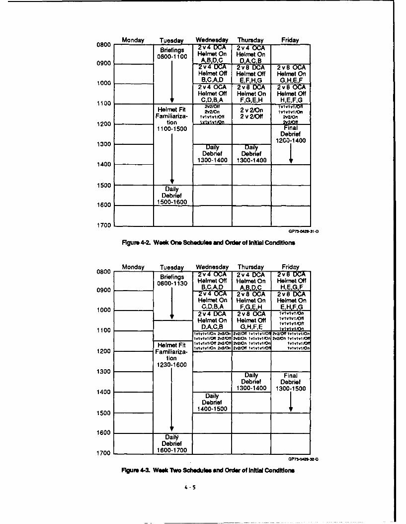
A run that began BVR (2v4 or 2v8) required approximately 10 minutes. A runthat began WVR (2v2 or ivlvlvl) required approximately 5 minutes. Four versionsof each BVR scenario were prepared. A different order of the four version wasgenerated by Latin square for each group of pilots and each offensive ordefensive condition. The scenarios are described below. The orders and testschedules are shown in Figures 4-2 and 4-3.
4-4
080 Monday -Tuesday Wednesday Thursday Friday080Briefings 2v C 2v4 OGA
08001100 Helmet On Helmet On0900 0800-1100 A,B,D,C 2vOA
2 U; 2v8 DCA 2v CI Helmet Off Helmet Off Helmet On1000 IB.C.A,D EF.HG G,H.E,F
I 2v4 OCA 2v8 DCA 2v800CAI Helmet Ott Helmet On Helmet Ott
110 ______ 4CD,B,A F,G,E.H H,E,F,GHelmet Fit Mv2,n 2 v 2/On I1v1vIv1In
Familiariza- lvi vivI/Off 2 v 2/Off M/O1n1200 tion vvio N0t
1100-1500 FinalDebrief
1300I ~12GO-1 400
IDebrief DebriefI1400 1 1300-1400 1300-1400 4
1500 DailyDebrief
1600 ____ 1500-1600 ______________
17001GP73-042-31 -D
Figure 4-2. Wee* One SctoWzlee aNW Order of Inltial Conditions
080 Monday Tuesday Wednesday Thursday Friday
Briefings Helmet Off Helmet On Helmet Ott
0900 00-10 B,CA,D A B.D.C H,E,G,F
Helmet On Helmet On Helmet On100C,D,B,A __________,F,
1002v4 DOA 2Y8 OCA lvlvlvl/OnHelmet On Helmet Off lvi vivl/ff
110D,A,C,B G,H,.E lvi viviiof1100Ivivivi/On 2v2On 2v2Off lvi vlvl/ 0fl 1lvlvlvIJ~n
IvivivI/Off Wv2oV 2v2i#ri Ivlvlvi10n 2v2/On IvIvIvI/fHelmet Fit Ivivivi/Off M(2Of 2v2/Onf lvlvlvli 1IvIvIvin
1200 Familiariza- ivvv/n22O v/f v ii iiii
1300 Daily FinalDebrief Debrief
1400 Diy 1300-1400 1300-1500
Debrief
1500 1400-1 500___ _______
1600 Dal
1700 Debief FFgRpm,4.-3 Week T"o Schedule and Order of lnll Condrtions
4-5

Simulator test time was approximately twelve hours per pilot. Thecombination of approximately twelve hours of testing per pilot and four hours offamiliarization results in almost twenty hours of simulator time per pilot. Forthe TAC demonstration, a total of approximately 40 hours was spent in thesimulator.
4.4 TEST SCENARIOS
Three basic scenarios were used: an Air Base Defense Scenario, a FighterSweep Scenario, and Visual Setups. The Base Defense and Sweep scenarios were setin the context of actual missions and involved up to ten aircraft (counting theF-15s). The visual setups involved only four aircraft, were less complex, andwere task rather than mission oriented.
4.4.1 Air Base Defense Scenario - The basic setup for this mission isshown in Figure 4-4. At the start of each run, the F-15 aircraft were positioned6000 ft. apart, line abreast, at 15,000 ft. MSL, Mach 0.8, heading 0900. Thestarting position was 10 NM east of the airfield that must be defended and 10 NMwest of the assigned CAP point. The FEBA was simulated by a north-south line 30NM east of the F-1 . The 1, 2, 3, and B points represent Nav destinations.These were displayed on the VSD when they were within 600 of the nose.
Initial F-15 Position FEBAHdg: 0900Aft: 15,000 MSLMach: 0.8
Airfield15N
10 NM 1ONM 02NM 15NM S
3:~Friendly Hostile
Figum 4-4. Air Base Dfens Setup
At the start of each run, the F-15s encountered a different mix of targets.The primary objective was to stop any bombers; however, there were at least twoenemy fighters in every run, and the F-15s had to defend themselves whilesearching for the bombers. Other blue aircraft were also present and were not tobe attacked. Typical initial conditions are shown in Figure 4-5.
4-6

NFEBA
W E Bombere1T Manned Red Fighters (MiG 23s)
S 1O,000/Mach 0.85
B F-15s 30,000'/Mach 0.95
-2 Red Bomber (MiG 23)2,000'/Mach 1.0 Digital Red Fighters
4 (MiG 21s)15,000'/Mach 0.9
3: 5,000'/Mach 0.8
Blue RecoveryBlue Aircraft (F-i5)Recovery (Returning to Base)
5,000'/Mach 0.9GP73-0201 40-
Figure 4-5. Typical Initial Conditions Air Base Dofer.m Scenario
During the Air Base Defense scenarios, the F-15s received GCI assistance,simulated by test operators, in locating and keeping track of all other aircraft.The AA[ was available and could be used to identify friendly aircraft.
Kill removal applied to red and blue team participants. Red bombersattempted egress to the east after reaching their targets. Other blue aircraftwere removed upon reaching the airfield.
Eight different setups were used for this scenario. Each setup involved adifferent number of aircraft and different ratios of aircraft type. Each setupwas performed twice: once with the HMD and once without the HMD. A total of 16Air Base Defense test runs were performed.
4.4.2 Fighter Sweep Scenario - The basic setup for this mission is shownin Figure 4-6. At the start of each run, the F-15 aircraft were positioned 6000ft. apart, line abreast, at 15,000 ft. MSL, Mach 0.8, heading 0900. The startingposition was 10 NM west of the FEBA, which is again simulated by a north-southline. The numbers shown represent Nay destinations. These are displayed on theVSD when they are within 600 of the nose.
FEBA
Initial F-15 PositionHdg: 0900 17Aft: 15,000 MSLMach: 0.8 " 15 NM
B
I : - 30 NM10 1NM4 10 NM~ 15'NM
Friendly HostileGP73-O49.29-D
Figure 4- Fighter Sweep Set Up
4-7

At the start of each run, the F-15s encountered a different mix of targets.The primary objective was to penetrate enemy territory, destroy as many enemyaircraft as possible while avoiding attack, and return to friendly territory.There were at least two enemy fighters in every run plus enemy bombers. Otherblue aircraft were present and these were not to be attacked. Typical initialconditions are shown in Figure 4-7.
BomberRoute
EFEBA
1 Manned Red Fighter (MiG 23)
10,000/Mach 0.85
F-15sBlue Digital Red Fighters (MIG 21 s)Route Blue Aircraft
(F-1) 20,oo0oMach 1.0 5,ooo0ach 0.825,000'/Mach 0.9 Manned Red Fighters (MiG 23s)
20,000VMach 0.95Red Bomber (MiG 23) N
31 15,000Vaach 0.9 Ei~W---' E
SQP7-OM0 .42-D
Figure 4-7. Typical Initial Conditions Fighter Sweep Scenario
During the Fighter Sweep scenarios, nn GCI was ava 4lable to Blue but wasgiven to Red. The AAI was available to identify friendly aircraft. All killremoval rules for the Air Base Defense scenarios were used in the Fighter Sweepscenarios and Red Aircraft that crossed the FEBA heading west were removed whenthey were 10 NM West of the FEBA.
Eight different setups were used for this scenario. Each setup involves adifferent number of aircraft and different ratios of aircraft type. Each setupwas performed twice: once with the HMD and once without the HMD. A total of 16Fighter Sweep test runs were performed.
4.4.3 Visual Setups - A ivlvlvl setup and a 2v2 setup were used. OnlyF-15 pilots and F-5 pilots participated in these runs. The primary purpose ofthese runs was to force the pilots into unprepared, quick reaction situations anddetermine if the HMD helps. An example of this might be a bugout following avisual turning fight when the pilot has not had an opportunity to establish radarsearch and is primarily in a visual mode.
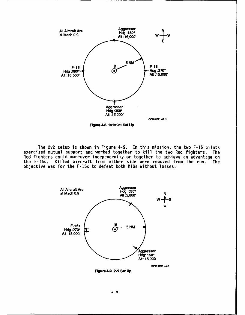
The IvIvivI setup is shown in Figure 4-8. The four pilots were placed onthe circumference of a 5 NM circle at different altitudes. All pilots had tomaintain the starting altitude until crossing the center of the circle. When thelast aircraft crossed the center of the circle, the test director called "fight'son" and the pilots could maneuver. Each participant could engage any otheraircraft. Kil.ed aircraft were removed from the run. The objective was to bethe sole remaining participant.
4-8
All Arcrft Ar Aggressor Nl-at Mach 0.9 - :1800 w
E
F-1 5 B5F-ISHdg :090270
Aft:16,50 AN :15,000'
AggressorHdg -360*
Aft :15,000'GPl-=21.4-
Figure 44. lvlvlvl Set Up
The 2v2 setup is shown in Figure 4-9. In this mission, the two F-15 pilotsexercised mutual support and worked together to kill the two Red fighters. TheRed fighters could maneuver independently or together to achieve an advantage onthe F-15s. Killed aircraft from either side were removed from the run. Theobjective was for the F-15s to defeat both MiGs without losses.
All Aircraft Are Aggressorat Mach 0.9 Hdg :0300 NAft :5,000' N
E
F-15sHdg 270*
Alt :15,000'
AgrssorHdg: 150*~Aft: 15,000
OP73-O -44-0
Figure 44. 2v2 Set Up
4"9
4.5 RULES OF ENGAGEMENT (ROEs
4.5.1 Air Base Defense ROE - These are the ROE followed during the testruns.
o All targets must be identified as hostile prior to weapon release.Identification may be accomplished by AAI, GCI, or visually.
o Aircraft will be removed from the scenario whenever any of thefollowing conditions occur:
- Any aircraft killed is removed.- Other Blue aircraft that reach the airfield are removed.
0 The Air Base Defense scenario will terminate when all Red aircrafthave been removed or at the expiration of 15 minutes from the startof the run, whichever comes first.
4.5.2 Fighter Sweep ROE
o All targets must be identified as hostile prior to weapon release.Identification may be accomplished by AAI, GCI, or visually.
0 Aircraft will be removed from the scenario whenever any of thefollowing conditions occur:
- Any aircraft killed is removed.- Any Red aircraft that cross the FEBA are removed 10 NM west of the
FEBA.- Other Blue aircraft that reach the airfield are removed.
0 The Fighter Sweep scenario will terminate when all Red aircraft havebeen removed, at the expiration of 15 minutes from the start of therun, or after the F-15s reach a point 15 NM west of the FEBA,whichever comes first.
4.5.3 IvIvIvI Visual Setup ROE
o Aircraft may not depart their assigned altitude until crossing thecenter of the circle.
o Aircraft may not engage prior to the "fight's on" call.
o After "fight's on" each participant may attack any of the other threeaircraft.
0 Aircraft are removed from the scenario when they are killed (BothBlue and Red).
o This scenario will terminate whenever any of the following conditionsoccur:
- Both F-15s have been removed.- Only one aircraft remains.- Time limit of 15 minutes is reached.
4- 10

4.5.4 v2 Visual Setup ROE
o Red fighters will only engage F-15s, and F-15s will only engage Redfighters.
o Aircraft are removed from the scenario when they are killed (BothBlue and Red).
0 This scenario will terminate whenever any of the following conditionsoccur:
- Both F-15s have been removed.- Both Red fighters have been removed.- Time limit of 15 minutes is reached.
4-11

5.0 RESULTS
A total of 101 runs were successfully completed. Of the 101 total runs, 27were IvlvIvi or 2v2 "visual scenarios", and 64 2v4 and 2v8 scenarios. While theivlvlvl and 2v2 scenarios could and often did evolve into BVR engagements and the2v4 and 2v8 scenarios could become visual engagements, the smaller scenarios weremore likely to include within visual range combat during the initial phase. Thelarger scenarios were presented equally often to both pilot groups becauseplanned presentations of the visual scenarios were sacrificed to maintain thetest plan for the larger scenarios, they could not be conducted equally often forboth groups or at regular intervals. Results of both scenario types will bediscussed following a summary of the types of data collected.
5.1 VARIABLES EVALUATED
The variables analyzed were chosen on the basis of three factors:availability, validity as a measure of tactical worth, and relationship to someaspect of HMD use. Availability refers to the ability to collect data during thesimulation, either from the simulation computers, or from the pilots themselves,as in the case of the SWAT (Subjective Workload Assessment Technique) workloadmeasure. Assessing the usefulness of the HMS/D in the tactical environment was aprimary objective of the test, and variables with high intrinsic validity asindicators of tactical worth (i.e., numbers of kills and losses) were included.Other variables were included in the hope they would provide information as tohow the HMS/D was used and how it affected the overall conduct of the mission ata more detailed level.
The 12 variables chosen are shown in Figure 5-1. The number of red andblue kills were the measures of tactical worth chosen for this analysis. The RedKills variable reflected losses of both manned Blue aircraft to either manned ordigital Red aircraft. Blue losses due to attacks by other Blue aircraft wereexcluded. The Blue Kills variables included all downed Red aircraft, regardlessof whether they were piloted MICS stations. Red fiohters or Red Bombers. Theeffectiveness of short-range weapons was separately assessed by the AIM-9Launches and AIM-9 Kills variables.
Blue Kills
Red Kills
Blue SWAT
Red SWAT
LOS/MUD
LOS/45
Supersearch
Boresight
First Time
First Range
AIM.9 Kills
AIM-9 LaunchesOP?3-42. 2 I
Figure 5-1. Variables Analyzed
5-1

Tactical utility, as reflected in increased kills and decreased losses, isa primary goal for the HMS/D. However, it is also desirable that this goal beachieved without the increased workload that might result from adding a newdevice to the cockpit. SWAT data were collected from the Blue pilots to assessthe effect of the HMS/D on pilot workload. The Blue SWAT variable reported wasthe average of the SWAT scores reported after each run by the Blue pilots. SWATdata were also collected from the Red pilots.
The remaining variables were analyzed with the expectation that someinsight into the use of the HMS/D would result. The LOS/HUD variable reflectedthe percentage of time the helmet sight indicated that the pilot's line-of-sight(LOS) fell outside the HUD, or, in other words, that the pilot was not lookingat, or through, the HUD. The LOS/45 variable indicated the percentage of timethe pilot's LOS was more than 45 degrees from aircraft boresight.
The helmet mounted sight could be coupled to the radar and used to slew theradar field of regard, while the helmet display showed the positions of targetswithin The radar field of regard. This allowed the pilot to designate targets inBoresight and Supersearch radar modes at offset angles that would otherwise betoo extreme. The Boresight variable was the number of designations of targetsoutside the normal field of regard in boresight mode. The Supersearch var-ablewas the number of designations of targets outside the normal field of regard inSupersearch mode.
The First Time variable was the time between the beginning of a simulatorrun and the first weapon launch by a Blue aircraft. The First Range was therange between the Blue aircraft and its target at the time of the first launch.It should be noted that this datum could only be collected when the first weaponlaunched was an AIM-7.
5.2 ANALYSIS OF HMS/D QUANTITATIVE DATA
The quantitative data were analyzed in two parts. The data from the largerscenarios were submitted to a rigorous analysis cf 'learning and HMS/D effects.This analysis also considered the pilot group (equivalent to the week of datacollection) as a Factor. The data from the visual scenarios were analyzed forcorrelation among the variables analyzed. This analysis is more tolerant of thevariation in types and order of scenarios, since data from each trial is beingcorrelated only with other data from the same trial. The results from the largerscenarios will be reported first, followed by the results from the visualscenarios.
The statistical analysis employed for the larger scenarios was an analysisof variance treating the HMS/D -- HMS/D on and off - (HMD), the week in which thedata were collected -- first or second (WEEK), and the block in which the datawere collected -- block 1, 2, 3, 4 (BLOCK), as factors. Each week was dividedinto four blocks of eight trails, four of which were completed with the HMD onand four of which were completed with the HMD off. The first two blocks werealways two-versus-four scenarios and the last two were always two-versus-eightscenarios. The interaction with the week of data collection will be discussed ata later point. Later blocks represent later trials where pilots had moreopportunity to learn to use the HMS/D effectively. The type of scenario (whether
5-2

air base defense or sweep) and the force size were not factors in the analysis,since the effect of practice over blocks appeared more consistent.
The model employed was a split-plot factorial design (cf. Kirk, 1982).Weeks of data collection was the between - subjects (blocks in Kirk'sdescription) treatment and HMS/D and block were within subjects variables. Forthis analysis, higher order interactions with the HMS/D factor were pooled withlower-order effects to form combined terms. Thus the interaction of HMS/D andblock includes the main effect of block and the interaction of the week of datacollection, HMS/D and block includes the main effect of week and both its two-wayinteractions. This model was small enough to be analyzed on the facilityavailable and provided an economy of presentation in this report as well. Thisapproach produces an analysis that has a greater chance of finding statisticallysignificant effects. It is also more likely than usual that some of the effectsreported would not prove reliable on further testing. This approach is justifiedin an attempt to discern a pattern in the diverse results of the study. Thispattern is one key to understanding how the HMS/D was used in this study. Itshould be expected that all future simulation would show the same results.
The results of the analysis of the Blue Kills variable are shown in Figure5-2. The HMS/D did not have an overall effect for the week, but did interactwith the block variable to affect performance in different ways during the week.Figure 5-3 illustrates this result. Slightly fewer kills were achieved by theBlue aircraft with the HMD on during the early part of the week, but performancewith the helmet improved dramatically in the final Y!.ck. An average of 1.5 morekills per run were achieved by the blue aircraft tvith the HMD during the finalblock.
Dependent Variable: Blue Kills
Source DF Type III SS Mean Square F Value Pr<F
HMD 1 0.02 0.02 0.01 0.920
HMD x Block 6 31.59 5.27 3.40 0.007
HMD x Block x Week 8 34.375 4.29 2.78 0.0131
Error 48 74.25 1.54 - -
G P83-0078.2 T
Figure 5.2. Analysis of Variance Summary Table for Blue Kills
5.3

4.0
.....HMD Off- HMD On
3.0
BlueKillsPerRun
2.0 .__._,""
1.0Block I Block 2 Block 3 Block 4
Week 1: 2V4 DCA Week 1: 2V4OCA Week 1: 2V8 DCA Week 1: 2V80CAWeek 2:2V4 OCA Week 2:2V4 DCA Week 2:2V8 OCA Week 2:2V8 DCA
GPM3-0078-015-0
Figure 5-3. Average Kills Per Run for Blue Aircraft
The defensive performance of the Blue aircraft does not seem to have beenaffected by the variables examined. Figure 5-4 shows the results of the analysisindicating no statistically detectable effects on the Red Kills variable. Figure5-5 bears out this conclusion, indicating that at no point was there as much as a0.5 aircraft difference in the Red Kill variable as a function of the presence ofthe HMD.
Dependent Variable: Red Kills
Source DF Type Ill SS Mean Square F Value Pr<F
HMD 1 0.14 0.14 0.19 0.6659
HMD x Block 6 1.59 0.27 0.36 0.8087
HMD x Block x Week 8 5.38 0.67 0.90 0.7484
Error 48 35.75 0.74 - -
GP83-0078.4-T
Figure 5-4. Analysis of Variance Summary Table for Red Kills
5-4

4.0HMD Off
- HMD On
3.0.3.0 -___
AverageKills 2.0PerR un.. . . . . .. . . . .. . . . . .. . .. . . . .
1.0/5error
0 ,°
Block I Block 2 Block 3 Block 4Week 1: 2V4 DCA Week 1: 2V40CA Week 1: 2V8 DCA Week 1: 2V80CAWeek 2:2V4 OCA Week 2: 2V4 DCA Week 2:2V8 OCA Week 2:2V8 DCA
GP63-0078-1 7-0
Figure 5-5. Average Kills Per Run for Red Aircraft
The workload of the F-15 pilots was reflected in the Blue SWAT variable.There was a significa.,t interaction among the weeks, HMS/D and block variablesdue partly to consistently higher SWAT scores reported during the second week.The highest SWAT scores were associated with the HMS/D during the first threeblocks of the second week as shown in Figure 5-6. The reversal of this trend inthe fourth block is responsible for the crossover shown in Figure 5-7. The SWATscores from the first week were more consistent with slightly lower scoresreported while using the HMS/D throughout the week.
Dependent Variable: F-15 Pilot Workload
Source DF Type III SS Mean Square F Value Pr< F
HMD 1 377.82 377.82 1.24 0.2710
HMD x Block 6 1548.55 258.09 0.85 0.54
HMD x Block x Week 8 15307.72 1913.46 6.28 0.0001
Error 48 14622.44 304.63 - -
GP83-00TS 3IT
Figure 5-6. Analysis of Variance Summary Table for F-15 Pilot Workload
5-5

100.... HMD Ofl- HMD On
90
80
70
60
Mean .. *
SWAT 50Response 40
30
20
10
0Block 1 Block 2 Block 3 Block 4
Week 1: 2V4 DCA Week 1: 2V40CA Week 1:2V8 DCA Week 1: 2V80CAWeek 2:2V4 OCA Week 2:2V4 DCA Week 2:2V8 OCA Week 2:2V8 DCA
GP03-0079-14-0
Figure 5-7. Average Blue Workload
The workload of the Red pilots, reflected in the Red SWAT variable, showeda more definite pattern. The statistical analysis shown in Figure 5-8 indicatesthat Red pilot workload was not affected by whether or not the Blue pilots wereusing the HMD, but that the HMD factor and the block factor together did have adefinite effect. Figure 5-9 shows the results graphically and suggests that Redpilot workload was higher when Blue pilots were using the HMD during the lastblock (and the first block), but was lower for the second and third block. Itwas felt that the first block was higher because the Red pilots had moredifficulty learning to fly the MICS than the Blue pilots had learning to fly theF-i5 cockpit. By the time of the last block the Blue pilots had been trainedsufficiently to "make life more miserable" for the Red pilots.
Dependent Variable: Red Pilot Workload
Source DF Type Ill SS Mean Square F Value Pr<F
HMD 1 5.64 5.64 0.03 0.8643
HMD x Block 6 6220.48 1036.75 5.42 0.0002
HMD x Block x Week 8 6155.88 749.48 4.03 0.001
Error 48 9174.50 191.14 - -
GP63-758-1 .T
Figure 5-8. Analysis of Variance Summary Table for Red Pilot Workload
5-6

100
...... HMD Off/Blue Pilots90 - HMD On/Blue Pilots
80
70
60
Percent of 50Run Time
40
30
0
Block 1 Block 2 Block 3 Block 4Week 1 2V4 DCA Week 1: 2V4OCA Week 1: 2V8 DCA Week 1: 2V80CAWeek 2: 2V4 OCA Week 2:2V4 DCA Week 2:2V8 OCA Week 2:2V8 DCA
GP$3-0078-16-O
Figure 5-9. Average Red Pilot SWAT Score
The percentage of run time each pilot spent with his LOS outside the HUDfield of view was not affected by the HMD or by the combination of the HMD andthe block, according to the analysis summarized in Figure 5-10. As graphed inFigure 5-11, the LOSHUD data suggest a consistent difference between the HMD onand HMD off conditions during the first three blocks, converging in the fourthand final block. Although the analysis of variance reported in Figure 5-10 wouldsupport this conclusion, one entire cell was missing from the data and thecorrectness of the results cannot be assured.
Dependent Variable: Percentage of Time Helmet Line of Sight
Was Outside the HUD
Source DF Type Ill SS Mean Square F Value Pr<F
HMD 1 86.81 86.81 0.59 0.44
HMD x Block 6 1251.36 208.56 1.43 0.22
HMD x Block x Week 7 14024.72 2003.53 13.72 0.0001
Error 43 6280.33 146.05 - -
GP83-00781 I.T
Figure 5-10. Analysis of Variance Summary Table forPercentage of Time Outside the HUD
5-7

100100......
HMD Off90 --- HMD On
70
60
Percent of 50Run Time
40
30 rr -r
20
10
0Block I Block 2 Block 3 Block 4
.Week 1: 2V4 DCA Week 1: 2V40CA Week 1: 2V8 DCA Week 1: 2V80CAWeek 2:2V4 OCA Week 2: 2V4 DCA Week 2:2V8 OCA Week 2:2V8 DCA
Go8-0074-20-0
Figure 5-11. Percentage of Time Pilot LOS Was Outside the HUD
The results of the analysis of the LOS45 variable, shown in Figure 5-12,are similar to those for the LOSHUD variable. There were significant differencesbetween the two pilot groups, including an effect of the HMD. The Blue pilotsduring the first week spent a substantially higher percentage of the time withtheir LOS more than 45 degrees off boresight during the two-versus-four scenariosthan did the pilots of the second week. When graphed, as in Figure 5-13, thedata suggest a tendency for higher off-boresight LOS angles during the earlystages of the evaluation, declining at the end of the week. Again, the resultsmust be interpreted cautiously due to the large number of missing values.
Dependent Variable: Helmet Line of Sight 450 or More Outside HUD
Source DF Type Ill SS Mean Square F Value Pr<F
HMD 1 104.01 104.01 6.09 0.0182HMD x Block 6 1253.31 208.88 12.23 0.0182HMD x Block x Week 5 1066.01 213.20 12.38 0.0001Error 38 648.92 17.08 - -
G P823.00 760T
Figure 5.12. Analysis of Variance Summary Table for Helmet Line of SightMore Than 450 Outside the HUD(Thirteen Values Were Missing)
5-8

100
...... HMD Off90 HMD On
80
70
60
PercentRun
Time40
30
20......
10
Block 1 Block 2 Block 3 Block 4Week 1: 2V4 DCA Week 1: 2V4OCA Week 1: 2V8 DCA Week 1: 2V8OCAWeek 2:2V4 OCA Week 2:2V4 DCA Week 2:2V8 OCA Week 2:2V8 DCA
GPS-O7S-1 -O
Figure 5-13. Percent of Time Pilot LOS Was More Than45 Degrees Off Boreslght
The HMD did have a significant effect on the Supersearch variable. Of the35 targets designated in Supersearch radar mode outside the HUD, 29 weredesignated while the HMD was in use. This is reflected in the significant maineffect for HMD in the analysis summarized in Figure 5-14. Most of thesedesignations occurred during the first week of the evaluation, accounting for theinteraction effect of week. Figure 5-15 illustrates these data, showing thegeneral tendency for targets outside the HUD to be designated in supersearch onlywhen the helmet was in use.
Dependent Variable: Designation of Targets Outside the HUD
While in Supersearch Mode
Source DF Type Ill SS Mean Square F Value Pr<F
HMD 1 6.89 6.89 8.22 0.0061HMD x Block 4 6.96 1.16 1.39 0.24
HMD x Block x Week 4 21.88 2.73 3.26 0.0148
Error 48 40.25 0.84 - -
GP73-0078.S-T
Figure 5-14. Analysis of Variance Summary Table for SupersearchDesignations of Targets Outside the HUD
5-9

1.5....HMD Off
-HMD On
1.0
AverageNumber
ofTarget
Designations
0.5
Block 1 Block 2 Block 3 Block 4Week 1: 2V4 DCA Week 1: 2V4OCA Week 1: 2V8 DCA Week 1: 2V80CAWeek 2: 2V4 OCA Week 2:2V4 DCA Week 2:2V8 OCA Week 2:2V8 DCA
oP93-oo78-2-o
Figure 5-15. Number of Supersearch Designations Outside HUD
Only seven targets outside the HUD were designated in Boresight mode, fourwith the HMD and three without it. The disorderly results with this variableshown in Figures 5-16 and 5-17 are not surprising, given the small amount ofdata.
Dependent Variable: Designations of Targets
Outside the HUD in Boresight Mode
Source DF Type III SS Mean Square F Value Pr< F
HMD 1 0.02 0.02 0.10 0.7491
HMD x Block 6 1.09 0.18 1.21 0.32
HMD x Block x Week 8 1.88 0.23 1.55 0.16
Error 48 7.25 0.15 - -
SPS3-OO7S-8.T
Figure 5-16. Analysis of Variance Summary Table for Designationsof Targets Outside the HUD While in Boresight Mode
5-10
0.40.. HMD off
0.35 ________ - HMD on
0.30
0.25AverageNumber________
Of 0.20DesignationsFun
WMerror0.15
Block 1 Block 2 Block 3 Block 4Week 2: 2V4 OCA Week 2: 2V4 DCA Week 2: 2V8 OCA Week 2: 2V D-CA
GP$3-MM-52"-
Figure 5-17. Number of Boreuight Mod. Designations Out of HUD
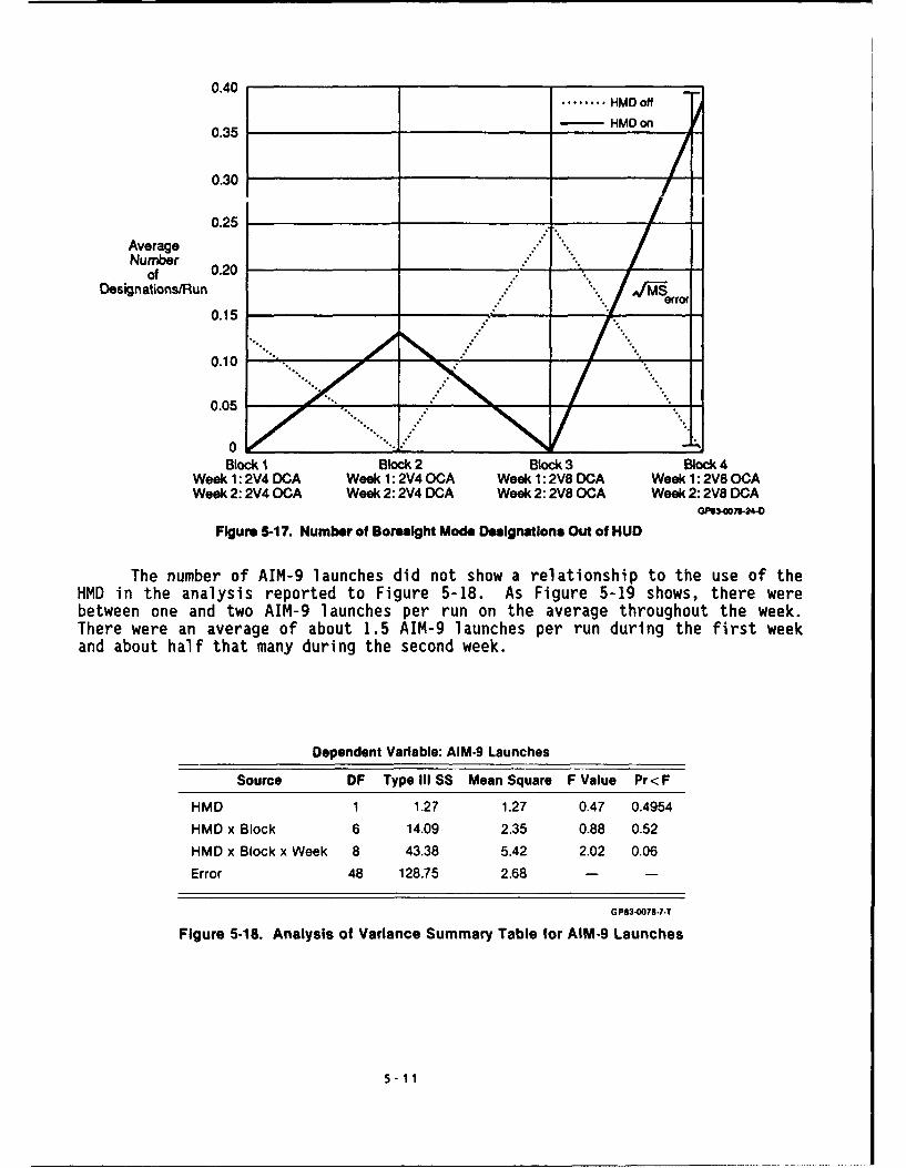
The number of AIM-9 launches did not show a relationship to the use of theHMD in the analysis reported to Figure 5-18. As Figure 5-19 shows, there werebetween one and two AIM-9 launches per run on the average throughout the week.There were an average of about 1.5 AIM-9 launches per run during the first weekand about half that many during the second week.
Dependent Variable: AIM.9 Launches
Source DF TypelIII SS Mean Square F Value Pr'<F
HMD 1 1.27 1.27 0.47 0.4954HMD x Block 6 14.09 2.35 0.88 0.52HMD x Block x Week 8 43.38 5.42 2.02 0.06Error 48 128.75 2.68 - -
GPS3-0078-7-T
Figure 5.18. Analysis of Variance Summary Table for AIM.9 Launches
5-11

2.5
-HMD ORf- HMD On
2.0
Average 1.5AIM-9
LaunchesPerRun 1.0
0.5
0Block I Block 2 Block 3 Block 4
Week 1: 2V4 DCA Week 1: 2V40CA Week 1: 2V8 DCA Week 1: 2V80CAWeek 2: 2V4 OCA Week 2:2V4 DCA Week 2:2V8 OCA Week 2:2V8 DCA
GP3-0078-22-O
Figure 5-19. AIM-9 Launches
The analysis shown in Figure 5-20 indicates that the number of Blue killsachieved by the AIM-9 missile was not significantly affected by the use of theHMS/D, experimental block, of the pilot group, or any combination of thesefactors. Examination of the data in Figure 5-21 suggests more AIM-9 kills wereachieved with the HMS/D than without it, except in the third block. Evidently,however, the reversal in the third block was sufficient to negate the trendfavoring the helmet that was otherwise apparent.
Dependent Variable: AIM-9 Kills by Blue
Source DF Type III SS Mean Square F Value Pr<F
HMD 1 0.14 0.14 0.27 0.6075
HMD x Block 6 1.97 0.33 0.62 0.71
HMD x Block x Week 8 6.63 0.83 1.57 0.16
Error 48 25.25 0.53 - -
GP83 )?84.T
Figure 5.20. Analysis of Variance Summary Table for AIM.9 Kills by Blue
5-12

0.90.... HMD Off
0.8HMDOn
0.7
0.6AverageNumber ."'""
of 0.5AIM-9
Kills 0.4 " -°Oo .*'
Run 0.3
0.2
0.1
0Block 1 Block 2 Block 3 Block 4
Week 1: 2V4 DCA Week 1: 2V40CA Week 1 2V8 DCA Week 1: 2V80CAWeek 2:2V4 OCA Week 2:2V4 DCA Week 2:2V8 OCA Week 2:2V8 DCA
GP83-0078-25-O
Figure 5-21. Average AIM-9 Kills Per Run
The time of the first launch was related to the use of the HMS/D. AsFigure 5-22 shows, there was no constant effect of the HMS/D, but there was aneffect of the HMS/D in combination with the block and the week of datacollection. Figure 5-23 demonstrates a very consistent tendency for a longerelapsed time between start of the run and the first launch during the early runs,diminishing as the week proceeded until there was no difference during the finalblocks. The difference between the time with and without the HMS/D diminishesfrom almost 20 seconds in the week to nearly zero at the end.
Dependent Variable: Time of First Launch
Source DF Type IISS Mean Square F Value Pr<F
HMD 1 654.52 654.52 0.31 0.5787
HMD x Block 6 75316.37 12552.73 6.01 0.0002
HMD x Block x Week 6 52769.81 8794.97 4.21 0.0022
Error 40 83540.08 2088.50 - -
GP83-0078-12.T
Figure 5-22. Analysis of Variance Summary Tat'e for
Time of First Launch
5-13

200
-HMD Off-HMO On
180
160 ""
Tie 140oAso
(Seconds)
120 .
100
80Block 1 Block 2 Block 3 Block 4
Wae 1: 2V4 DCA Week 1: 2V40CA Week 1: 2V8 DCA Week 1:2V8OCAWeek 2: 2V4 OCA Week 2:2V4 DCA Week 2:2V8 OCA Week 2:2V8 DCA
GP83-O07-21 -O
Figure 5-23. Average Time From Start of Run to First Launch
Range at first launch data was only available when the first launch was anAIM-7 launch, contributing to the large number of missing values for thisvariable:see Figure 5-24. Nevertheless, during the two-versus-four missions inblocks I and 2 in Figure 5-25, the first launch consistently came at a greaterrange when the HMS/D was in use. This trend was reversed in block three, thefirst block of two-versus-eight missions, but then seemed to reassert itself inblock four, but no statistically significant trend emerged. Two cells weremissing entirely from the data, so the statistical results must be interpretedcautiously.
Dependent Variable: Range at First Launch
Source DF Type III SS Mean Square F Value Pr<F
HMD 1 15472263.82 15472263.82 0.34 0.56
HMD x Block 6 486122233.41 81020372.23 1.76 0.13
HMD x Block x Week 6 314676668.87 52446111.48 1.14 0.36
Error 38 1749832050 46048211.9 - -
GP83-0078.9.T
Figure 5-24. Analysis of Variance Summary Table forRange of First Launch
(Thirteen Values Were Missing)
5-14

30
..... HMD Off-HMD On
25MeanLaunch i.. ...Range - 4..........
Thousands .... ....ofFeet 20
errol
15Block 1 Block 2 Block 3 Block 4
Week 1: 2V4 DCA Week 1: 2V40CA Week 1: 2V8 DCA Week 1: 2V800AWeek 2:2V4 OCA Week 2:2V4 DCA Week 2:2V8 0CA Week 2:2V8 DCA
GP3-007) 75-1O
Figure 5-25. Range at First Launch
The differences between the weeks of data collection in mission success aresummarized in Figure 5-26. Exchange ratios were very favorable to Blue aircraftduring the first two blocks of week one. Difficulties expevienced by Red pilotsflying the MICS stations were probably a major factor here. Changes in trainingand in the flight models used were incorporated for the second week. The resultsfor the first two blocks of the second weeks show lower exchange ratios. In bothweeks (except the first two blocks of week one) there is a slight disadvantagefor the helmet until the final block. Also, in both weeks, there was asignificant advantage for Blue aircraft when the HMS/D was in use. When the dataof both weeks are averaged together the exchange ratio for the final block was3.75 with the HMS/D versus 1.8 without. This result will be discussed further inSection 6; he important point here is that the same trends were present in bothweeks.
5-15

5:1
Week TOne HMO OffHMD ON
2v4
Exchange 3:1 ! 4
Ratio 2:1
1:1
0:0Block 1 Block 2 Block 3 Block 4
Weekl1: 2V4 DCA Weekl1: 2V40CA Weekl1.:2V8 DCA Weekl1: 2V8O(:CAWeek 2: 2V40OCA Week 2: 2V4 DCA Week 2: 2V80OCA Week 2: 2V8 DCA
GPSS3-00 71-3o-OFigure 5-26. Exchange Ratios for Each Week
The results of the visual engagement did not lend themselves to any clearinterpretation. In the Ivivivi scenario, slightly better results were achievedwith the HMS/D than without it: 0.85 average Blue kills per mission with the
HMS/D versus 0.75 without it and 0.69 Red kills when the F-i5 pilots used theHMS/D versus 0.75 when HMS/D was not in use. The corresponding exchange ratiosare 1.23 with the HMS/D and 1.00 without it. The results in the 2v2 scenariowere less distinct. An average of 1.30 Blue kills per mission were obtained both
with and without the HMS/D. Red kills averaged 0.90 per mission when the HMS/Dwas in use compared to 0.80 when it was not.
The results from the visual scenarios were also cross-correlated to formtwo correlation matrices, one for trials without the HMS/D (Figure 5-27) and onefor trials with it (Figure 5-28). The entry in each cell in this matrixrepresents the tendency for two variables to vary together. A value nearpositive one indicates a strong direct relationship, a number near negative oneindicates a strong inverse re' 'ionship.
5-16

Blue Blue Boresight Supersearch Blue Red AIM.9 AIM.9 Time ot LOS LOS 45*
Kills Losses Outside Outside Swat Swat Launches Kills First Outside OutsideHUD HUD Launch HUD HUD
Blu , 00000 -31 8888 0 27060 -0)03217 -03 9542 - 0 3b930 3 jQ44' 0 69584* - 1304,48 -01
B2ue ' 3674 -006989 0!6189 -0 48374 -0 26,69 -043183 -0 08784 -0 9
84' esq180res~gnt
usce 0 15019 -0 32410 -0 49009* 0 29841 0 46402* -0 05816 -2 293 - c6HI0
Su 0esea rcOutside 0 31453 3 33034 0 '2373 0 14712 -0 '7603 0 '5581 0 36s3'HUBD
Blue Swa! 0 55184" -3 14326 -0 18746 -0 07361 0 55438" 0 39265
Rea S ,at -0 13120 0 02184 0 17442 0 7'1936* 0 4t-567 "
AIM 9 0 78700* 0 04914 -0 !5630 -Z!8 65-duflCIE
A -005448 -0 '0035 -0s004K¢, S
fime ofF rs1 0 27925 -0 147.0Launch
Os0ulsiOe 0 58880"
HUD
LOS 45u
Sndlrates a i'e aVion i'q,I 'l.l c e e aecteC 1n 'ewer 'an 5 f 100 cases
GP83-00e-28-T
Figure 5-27. Correlation Matrix for Visual Engagements With HMD On
Time of LOS LOS 450Blue Blue Blue Red AIM-9 AIM-9 irs OS OSide
Kills Losses Swat Swat Launches Kills Launt Oud OudLaunch HUD HUD
Blue Kils 1 00000 -0 07176 -0 48773" -0 19159 0 56380* 0 57387" 0 30797 -0 10530 -0 35927
Blue Losses 0 23528 0 19367 -0 30500 -0 47875" 0 20309 0 26043 0 29395
Blue Swat 005754 -0 40484 -0 65612 -0 35349 0 49983" 0 22226
Rea Swat -0 37842 -0 21844 0 19687 0 38215 0 15705
ANIM 9 0 61884 0 06906 -0 15388 -0 09231
Launches
AiM9 Kills 0 24071 -0 19661 -0 24306
Time ofFirst 0 05082 - 0 04866
Launch
LOSOutside 0 48924"HJO
LOS 450
.utsideHOD
,I i o ,'' , e e '1 re, ,e,'ijr '1i] j'es
GPe3-0078-29-T
Figure 5.28. Correlation Matrix for Visual Engagements With HMD Off
5-17

Some high correlations emerged in both matrices. Blue kills werecorrelated with AIM-9 launches and AIM-9 kills both with and without the helmet.AIM-9 kills were also correlated with AIM-9 launches and the two LOS measureswere correlated in both cases. Without the helmet, Blue kills were alsocorrelated with blue SWAT scores, which was correlated in turn with AIM-9 kills.These variahles were not correlated when the helmet was not in use. Fivevariables correlated with Red SWAT scores when the HMS/D was in use. Theseincluded the Red kills variable. The number of designations outside the HUD inboresight mode, Blue SWAT scores, and both LOS variables. The correlations withRed kills and boresight mode designation were negative. There was also anegative correlation between Red kills and the LOS45 variable, and positivecorrelations between boresight designations and AIM-9 kills and Blue SWAT and LOSHUD.
5.3 QUALITATIVE DATA SUMMARY
Each day during the tests pilot comments were collected during debriefingsessions, and the pilots completed questionnaires at the end of the tests. Theypointed our several distinct tactical advantages of the HMS/D and made somerecommendations for improving the present system. Half of the pilots were soimpressed with the tactical advantages that they recommended classifying theprogram.
5.3.1 Tactical Advantages - The following summarizes pilot comments andresponses about the advantages of the HMS/D.
1. Easier to perform radar acquisition within visual range (WVR).
This is one of the features the pilots liked best. Presently, when an F-15pilot sights another aircraft, he must rapidly decide which of four automaticacquisition modes he will use: Vertical Scan, Supersearch, Boresight, or AutoGuns. Tradeoffs between these modes include ease of use and speed ofacquisition. The pilot must quickly assecs these and choose the best mode forthe present situation.
The HMS/D helped this problem considerably by reducing the choices to onlytwo modes: a wide search mode (helmet "supersearch") and a narrow, focused mode(helmet "boresight"). Both modes were slaved to the helmet, making both veryeasy to use. The only decision was whether the situation dictated the higheraccuracy available in the helmet boresight mode. Normally, this accuracy wouldbe required only if the pilot had to select his target from two or more that arevery close together (e.g., supporting an engaged wingman who is in a tightturning fight).
2. The HMS/D provided considerable assistance in obtaining andmaintaining visual sighting of a previously acquired target.
One of the Aggressor pilots stated, "Anything that points your head andputs your eyes on the target will give you a significant advantage." All pilotsagreed that the HMS/D with the pointer arrow and TD box accomplished this.Pilots have used TD boxes for some time, but they have always been restricted tothe HUD field of view which means that he has to point the aircraft at thetarget. That is not always tactically sound.
5-18

Pilots found the ever present TD box on the HMS/D enabled them to taketheir eyes off a visual target to clear their 6:00 o'clock or to check theposition of another aircraft maneuvering near them. They could do this becausethey had steering to place their eyes quickly back onto the original target.Without the HMS/D they tended to remain "padlocked" on the target, often missingother nearby aircraft.
The TD box also enabled them to determine if the canopy bow, magneticcompass, or other aircraft obstruction was currently blocking their view of thetarget. Once this could be observed, a pilot could easily compensate, by movinghis head or the aircraft. However, after observing this, all the pilots wonderedhow many times in the past a similar obstruction had caused them to miss theinitial visual sighting of a target acquired through radar.
3. The HMS/D saved time in visual attacks.
The "first sight" advantage is often the most significant one. In an ageof all-aspect IR missiles, first sight often translates into the kill, becauseupon sighting, the pilot points the aircraft at the target, directs the seekerinto self-track, and shoots as soon as seeker track is confirmed. However,pointing the aircraft can impose a 10 to 15 second time delay. This could be allthe time needed for a fighter equipped with the HMD to get the first shot.
The HMD turned into a time saver in one other fashion. Because theSidewinder seeker line of sight was available, the pilot did not need to pointthe HUD at the target to confirm that the missile was in fact tracking thedesired aircraft. Thus, the pilots could launch off boresight with greaterconfidence. The pilots themselves cautioned that this tempted them to take badshots at times (e.o , out of range when the radar lock on step was omitted), butthey felt they couiu train to eliminate this tendency.
4. It is very helpful to have weapons data available when visually"padlocked".
The pilots liked the capability of observing the shoot cue and cargetidentification (e.g., IFF) without having to look at the HUD. The pilots feltthat this capability enabled them to exercise visual search more freely sincethey did not have to watch the HUD and/or radar to determine when launch criteriahad been satisfied or when the identification had been obtained. In some cases,the pilot was already lining up his next shot while waiting for a radar target toreach in range, firing his first missile on the HMD shoot cue. This wasespecially helpful when the next target had been acquired visually.
The pilots said they would like to see AIM-7 time-to-go on the HMS/D.
The ability to launch visual AIM-9 missiles while performing AIM-7missile illumination is a big improvement.
During the AIM-7 time of flight, the pilot must restrict his maneuvering tokeep from losing the target out of the radar field of regard. When anothertarget is visually acquired, the pilot must maneuver carefully in any attempt tolaunch an AIM-9, since maneuvering may result in loss of the previously launchedAIM-7. The HMS/D made this situation easier to handle, since the pilot couldpoint the AIM-9 with the helmet, and continue to fly his present flight path forAIM-7 guidance.
5-19

6. With the HMS/D there is no need to sacrifice BFM (basic fightermaneuvers) to launch AIM-9 L/M missiles.
The HMS/D resolved the dilemma of giving up positional advantage to go fora quick kill or maintain positional advantage, but prolong the fight. The HMS/Dpermitted the pilots to use the full maneuverability of the missiles tosupplement the aircraft's maneuverability and achieve the best of both options inhis tactics.
7. With the HMS/D there is no need to sacrifice BFM to perform fullsystem gun attacks.
The pilot often has to perform considerable BFM maneuvering to obtain a gunattack. Though seldom the weapon of choice, the pilot may be forced into usingthe gun in a very tight turning fight. The gun can be fired completely visually,estimating the necessary lead angles. However, the more ideal attack isperformed using the radar to obtain a track on the target. This enables theaircraft computer to determine lead for the pilot and position the gunsightaccordingly. The pilot can use auto-acquisition methods to get the radar track,but sometimes, the necessary BFM makes this difficult to accomplish. As with theAIM-9 attack, the HMD makes it possible to obtain radar track without sacrificingthe BFM. This means that the radar has a chance to settle down, and it willprovide good information as the pilot prepares to take the gun shot.
The following summarizes the pilots' suggestions for improvement of theHMS/D.
1. Remove the horizon line and heading scale.
None of the pilots found these particularly useful. They intended toignore these items at first, and when they discovered that we could remove themfor the test, all requested that they be removed. Half of them felt the same wayabout the airspeed and altitude numbers.
2. Concentrate on the WVR environment.
The pilots did not feel that the HMD provided a significant advantage inthe BVR environment. They preferred using the available cockpit displays for BVRwork, and felt that the HMD did not add to present capabilities. However, allfelt it was a major improvement for WVR operations, and all stated that theyneeded these capabilities now.
3. The field of view should be slightly lar!er.
All pilots commented that the present HMS/D (120 FOV) forced them to chasethe TD box on occasion in an attempt to keep it within the HMD FOV. Theysometimes found this activity counter-productive. When asked what they thoughtwould be a more useful size, they agreed that something approaching the size ofthe HUD FOV would be desirable. The present HUD FOV is approximately 200.
5-20

6.0 CONCLUSIONS AND RECOMMENDATIONS
The data are consistent with the theory that a combination of 1) pilotslearning to use the HMS/D, and 2) adapting the HMS/D pilot vehicle interface tothe individual pilot (in the form of customized declutter modes, and letting thepilots choose their preferred helmet and cockpit) provided a significant tacticaladvantage when using the HMS/D during the last block of test data. Introducingnew equipment or a performance feature in a system typically causes performanceto initially decrease while the operator relearns how to use it. Thenperformance will increase as he begins to capitalize on the added capability.
The advantaged gained with the HMD/S may have been accentuated by thetwo-versus-eight scenarios in blocks three and four. In these larger scenarios,it was more difficult for the pilots to track all Red aircraft in BVR, andunexpected encounters at short range seemed to be more frequent. It wasanticipated that the HMS/D would provide an advantage in these WVR circumstances.
Figure 6-1 shows the changes in exchange ratio as a function of the testblock and whether the HMS/D was on or off. Figure 6-2 shows the changes in Redand Blue workload for the same conditions. Data for the first block isquestionable because the pilots were still learning the simulation. Theadjustment was particularly difficult for the Red Pilots flying the MICSstations. When the first block data are excluded, the exchange ratio data ofFigure 6-1 shows that there is an advantage for the HMD off condition during themiddle (Blocks 2 and 3) of the testing period. Similarly, Figure 6-2 shows thatduring blocks 2 and 3, Blue pilot workload is lower and Red pilot workload higherwhen the Blue pilots had the HMS/D off. Both trends are dramatically reversed inthe fourth block however.
4.0
..... HMDoff, - HMD on
3.0
BlueKill:RedKill
ExchangeRatio
2.0 ,- ...._ _ ."
1.01 2 3 4
Block GP734429-27-O
Figure 6-1. Exchange Ratio Results
6-1
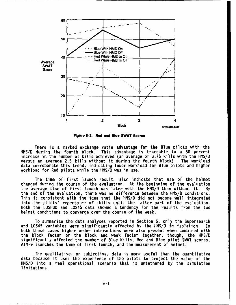
60
50
Blue With HMD On-Blue With HMD Off
40 --- 'Red While HMD Is OnAverage ... Red While HMD Is OffSWAT . /Score " " ., "
. ro
30 2
202
23 4Block GP.0429-2O
Figure 6-2. Red and Blue SWAT Scores
There is a marked exchange ratio advantage for the Blue pilots with theHMS/D during the fourth block. This advantage is traceable to a 50 percentincrease in the number of kills achieved (an average of 3.75 kills with the HMS/Dversus an average 2.5 kills without it during the fourth block). The workloaddata corroborate this trend, indicating lower workload for Blue pilots and higherworkload for Red pilots while the HMS/D was in use.
The time of first launch result. also indicate that use of the helmetchanged during the course of the evaluation. At the beginning of the evaluationthe average time of first launch was later with the HMS/D than without it. Bythe end of the evaluation, there was no difference between the HMS/D conditions.This is consistent with the idea that the HMS/D did not become well integratedinto the pilots' repertoire of skills until the latter part of the evaluation.Both the LOSHUD and LOS45 data showed a tendency for the results from the twohelmet conditions to converge over the course of the week.
To summarize the data analyses reported in Section 5, only the Supersearchand LOS45 variables were significantly affected by the HMS/D in isolation. Inboth these cases higher order interactions were also present when combined withthe block factor or the block and week factor together, though, the HMS/Dsignificantly affected the number of Blue Kills, Red and Blue pilot SWAT scores,AIM-9 launches the time of first launch, and the measurement of helmet.
The qualitative, or subjective, data is more useful than the quantitativedata because it uses the experience of the pilots to project the value of theHMS/D into a real operational scenario that is untethered by the simulationlimitations.
6"2

The pilots said that the HMS/D made it easier to do WVR radar acquisitions,and get visual sightings of acquired target, saved time in WVR attacks, providedhelpful weapon data while visually tracking a target, and added tacticscapability by easing simultaneous AIM-9 and AIM-7 attacks, and avoidedsacrificing BFM (basic fighter maneuvers) to launch an AIM-9 or perform a fullsystem gun attack.
They were particularly impressed with the time saved in a WVR attack andthe ability to make AIM-9 launches while maneuvering.
In several of the test engagements, the Aggressor pilot obtained the firstsighting, while the aggressor maneuvered to shoot, the F-15 pilot spotted him.Because the F-15 pilot was HMS/D equipped he did not have to maneuver hisaircraft and was able to launch the first missile. This generally had one of tworesults:
o The Aggressor was killed before he was able to complete the pointingmaneuver. Therefore, he never got the shot off.
o The Aggressor had to break off his attack and defend himself from amissile launched by the Eagle pilot. While the Aggressor wasoccupied in this fashion, the Eagle pilot maneuvered to a position ofadvantage.
In either case, the F-15 pilot was able to rapidly turn a bad situationinto one where he had the upper hand because he could direct his IR missileseekers without having to perform an aircraft maneuver. The pilots referred tothis capability as a "looks could kill" system, and one pilot stated that thecombination of the HMD and the AIM-9 L/M should be called "hamburger helper".They felt that this capability was the greatest advantage of the HMD.
One of the pilots said, "The time saved using the helmet could be onepilot's lifetime."
Currently, the only way to launch an AIM-9L/M missile visually is to pointthe aircraft so that the target is within the seeker field of view.Unfortunately, pointing directly at the target aircraft may not be a soundtactical move. If the target is in a high G break turn, the pilot may need tomaneuver out of the plane of the turn in order to maintain his positionaladvantage (i.e., remain behind the target). In pointing at the target, thetarget's turn may succeed in forcing the attacker into a neutral situation whereneither has a clear cut advantage. The fighter pilot is faced with the choice ofwhether to go for the quick kill or to maintain his positional advantage. If heopts for the quick kill, the missile may fail to guide or fuse, and the pilot maylose his advantage with nothing gained. If he maintains his positionaladvantage, the fight is prolonged, and other enemy aircraft are given a chance toreach the fight and support the target.
With the HMS/D, the F-15 pilot can have it both ways. He flies theaircraft as necessary to maintain the advantage, because it is not required thathe point at the target for seeker acquisition. While performing good BFM, heuses the helmet to drive the seeker onto the target. Then, when he achievesmissile parameters, he launches the missile. This enables him to accomplish avisual missile attack without sacrificing positional advantage.
6-3

Overall, all pilots (including the Aggressor pilots) who performed theHMS/D evaluation thought that this was a vital system and one that is needed inpresent fighter aircraft. As one fighter pilot stated, "The advantage of havingthe HMD over having just a HUD is like the difference between CCIP (constantcomputing impact point) and an iron bomb sight." In other words, pilots feel theHMS/D provides as much improvement to air-to-air operations as weapons computershave provided in air-to-ground operations.
These results indicate the development of the HMS/D system should continue.There were areas of improvement that should be taken care of before the systemwould become operational. These should be addressed with simulations,engineering flight tests, and additional vendor work to improve the design andsystem integration concepts.
6-4

LIST OF ABBREVIATIONS
A/A Air to AirA/C AircraftA/D Air DataA/G Air to GroundAAI Air-to-Air InterrogateACM Air Combat ManeuveringACS Armament Control SystemADI Attitude Director IndicatorAGL Above Ground LevelAHRS Attitude-Heading Reference SetASL Azimuth Steering LineATO Air Tasking OrderAUTO AutomaticAVMUX Avionics Multiplex Bus
BARO BarometricBDA Bomb Damage Assessment
C2 Command and ControlCAS Calibrated AirspeedCC Central ComputerCCC Central Computer ComplexCLNC Clearance (for TF operations)CLR ClearCNI Communication Navigation IdentificationCRT Cathode Ray TubeCRS Course
DBS Doppler Beam SharpeningDCLTR DeclutterDDU Display Driver UnitDEST DestinationDPT Display Processor/TrackerDRD Data Readout DisplaysDTM Data Transfer ModuleDWN Down
EADI Electronic ADIEHSI Electronic Horizontal Situation IndicatorEMERG EmergencyEMIS LMT Emission LimitENTR EnterEO Electro-Optical
7-1

LIST OF ABBREVIATIONS (Continued)
FEBA Forward Edge of Battle AreaFLIR Forward Looking InfraredFOg Field of ViewFWD Forward
G GravityGC Gyrocompass
HBST Helmet BoresightHDD Head Down DisplayHDG HeadingHMD Helmet Mounted DisplayHOTAS Hands on Throttle and StickHSD Horizontal Situation DisplayHSEL Heading SelectHSS Helmet SupersearchHUD Head-Up Display
I/P Identification of PositionIDENT IdentificationIFF Identification, Friend or FoeIIR Imaging InfraredIMC Instrument Meteorological ConditionsIN RNG In RangeINS Inertial Navigation SystemIP Inscu..tor PilotIR Infrared
JTIDS Joint Tactical Information Distribution System
K KnotsKCAS Knots, Calibrated Air SpeedKT Knot
LOS Line of Sight
M MachM/V Magnetic VariationMACS Manned Air Combat SimulatorMAN ManualMAV MaverickMC Mission Computer (see CC)MCAIR McDonnell Aircraft CompanyMDEC McDonnell Douglas Electronic CompanyMICS Manned Interactive Control StationMK Mark
7-2

LIST OF ABBREVIATIONS (Continued)
ML Mental Effort LoadMPCD Multipurpose Color DisplayMPD Multipurpose DisplayMR MilliradianMRM Medium Range MissileMSIP Multi Staged Improvement Program
NAV NavigationNAVDSG Navigation DesignationNCI Navigation Control IndicatorNM Nautical MileNMPP Nautical Miles per PoundNORM Normal
O/S OffsetOFP Operational Flight Program
PACS Programmable Armament Control SetPOSN PositionPP Present PositionPPI Plan Position IndicatorPRF Pulse Repetition FrequencyPRI Priority
RAM Raid Assessment ModeRDR RadarRDY ReadyRF Radio FrequencyRNG RangeROE Rules of EngagementRTCL ReticleRWR Radar Warning Receiver
SAC Strategic Air CommandSAR Synthetic Aperture RadarSCL ScaleSL Psychological Stress LoadSRM Short Range MissileSTAN EVAL Standard EvaluationSTBY StandbySTOR StoreSTT Single Target TrackSWAT Subjective Workload Assessment Technique
TAC Tactical Air CommandTACAN Tactical Air NavigationTBD To Be Determined
7-3

LIST OF ABBREVIATIONS (Concluded)
TCN TACANTD Target DesignatorTDC Target Designator ControllerTEWS Tactical Electronic Warfare SystemTF/TA Terrain Following/Terrain AvoidanceTGT TargetTHRT ThreatTL Time LoadTOT Time Over TargetTP Target PointerTWS Track While Scan
UFC Up Front ControlUHF Ultra High Frequency
VIS Visual
WACQ Wide AcquisitionWFOV Wide Field of ViewWPN WeaponWYPT Waypoint
7-4

APPENDIX AHELMET MOUNTED DISPLAY FORMATS
WEAPONS EMPLOYMENT
Three weapons-related symbols were provided: a Shoot Cue, a SidewinderSeeker LOS Circle, and a Breakaway "X".
Missile Shoot Cue - When MRM or SRM was selected with the Weapon Selectswitch and the radar was in STT, a Shoot Cue was provided for the tracked target.When the target was within the HMD FOV, the Shoot Cue was provided for thetracked target. When the target was within the HMD FOV, the Shoot Cue was atriangle attached to the bottom of the TD box (the same symbol used on thecurrent F-15 HUD). When the target was not in the HMD FOV, the Shoot Cue was atriangle embedded in the TP arrow 10 mils from the end of the arrow. Bothsymbols are illustrated in Figure A-i.
ShootaCue
440K2 22.6
a. Tare Wihi ' II
b. Target Outside HMD FOV
0P73-0201 -31-0
Figure A-1. Misslle Shoot Cue for Tracked Target
The criteria for this Shoot Cue were identical to those required for itsdisplay on the HUD. Like the HUD symbol, it flashes or remained steady as afunction of target range when MRM was selected.
A-I

Sidewinder Seeker LOS (Aim-9 L/M) - The operation of the AIM-9 L/M seekerwas changed to slave the seeker to the helmet LOS instead of aircraft boresightwhen the radar was in search or if manual boresight was selected. The possiblecases are described below and illustrated in Figure A-2.
017 017
440K 22.6 U0K 22.6a. Seeker Slaved to Helmet b. Seeker at Gimbal Umit
- Radar in Search Mode, or While Slaved to Helmet- Manual Guesight Pressed
01701
0440K( 22.6 G 440K 22.6
c. Seeker Slaved to Radar LOS d. Seeker Uncaged- Missile and Radar Are
Tracking Separate Targets
Figure A-2. AN" L/M Slde winc Disp/s GP75-C-320
a. Radar Not In Track - When the radar was in a search mode, the missileseeker was slaved to the helmet. This was indicated by display ofthe 25 mil Sidewinder Seeker Position Circle. If the helmet LOS waswithin the gimbal limits of the seeker, the seeker was slaved to thehelmet LOS, and the seeker circle was displayed in the center of theHMD FOV, as shown in Figure A-2(a).
If the helmet LOS exceeded the seeker gimbal limits, then the missileseeker remained at the limit and its location relative to the helmet wasindicated by a solid half-circle at the 2dge of the HMD FOV. This condition isshown in Figure A-2(b). If the pilot continued to move his head, the seekerremained at its gimbal limit, but it shifted in azimuth and elevation so as toremain on a radial from the helmet LOS to the aircraft boresight line. Thiscontinued until the HMD LOS was again within the seeker gimbal limits, at whichtime the seeker was again slaved to the helmet and moved in conjunction with headmovements.
b. Radar Tracking, Seeker Slaved to Radar - When the radar tracked atarget, the missile seeker was slaved to the radar LOS. The pilotcould observe proper slaving by aligning his head so that the
A-2

radar/seeker LOS was within the HMD FOV. The pilot could thenobserve both the TD box, indicating the radar LOS, and the Sidewinderseeker position circle, indicating the seeker LOS. The pilot coulddetermine whether the seeker was slaved to the radar by notingwhether the seeker circle was superimposed over the TD box, asillustrated in Figure A-2(c). Note that when neither LOS was withinthe HMD FOV, the TP Arrow could be used to locate the tracked target.
c. Radar Tracking, Missile Manually "Boresiohted" - If the seeker wasslaved to the radar LOS, depressing and holding the AIM-9 L/M ManualBoresight button on the right throttle slaved the seeker to thehelmet in the same fashion as described above. Thus, when the helmetLOS was within the seeker gimbal limits, the seeker was slaved to thehelmet LOS, and when the LOS exceeds seeker limits, the seekerremained the limit and the half-circle symbol was displayed on theHMD. The seeker remained slaved to the helmet while the ManualBoresight switch was held depressed, assuming the seeker was caged.
d. Seeker Uncaed - The seeker was uncaged from any of the abovelocations by pressing the Uncage button on the Stick. The seekerwould then attempt to enter self-track. The seeker position wasindicated by the seeker circle, which was then positioned as requiredto indicate seeker LOS. Proper seeker tracking could be confirmed byobserving the location of the seeker circle relative to either t'-- TDbox (target tracked'by radar) or the actual aircraft (target visuallyacquired). Figure A-2(d) illustrates a situation where the radar andthe AIM-9 missile are tracking separate targets.
This feature enabled the pilot to observe Sidewinder seeker statusand launch the weapon at high off-boresight angles. Thus, using onlythe HMD, it was possible to visually acquire the target at a highoff-boresight angle, lock on with the radar, uncage the AIM-9 seeker,confirm seeker track, and launch the missile (based on the Shoot Cue)without ever having had the target within the HUD FOV. In a shortrange situation the pilot could place the seeker directly onto thetarget using the HMD without radar acquisition.
Breakaway "X" - The Breakaway "X" symbol is shown in Figure A-3. It wasdisplayed on the HMD whenever range to the radar tracked target was at or belowminimum range for the weapon selected. It was displayed for the same conditionsused for its display on the HUD and the VSD. The "X" was centered on the HMD FOVand blinked at a rate of 2.5 Hz. Each side of the X was 125 mils long.
017
440K 22.6,-GP73-0201-33-0
Figure A-3. Breekaway "IX'
A-3

AIR-TO-AIR INTERROGATOR (AAI) OPERATION
The HMD displayed AAI symbols for targets when the radar was in STT, TWS,or RAM and the AAI button was depressed. Operation required prior AAI setup interms of mode desired, codes to be interrogated, etc. The HMD served merely asan additional display medium which duplicated some VSD displays.
Symbols Used - Small circle and diamond symbols (similar to those providedon the VSD radar displpy) were used. The symbols were positioned at the top ofthe TO box, as shown in Figure A-4. The symbol used was identical to the symboldisplayed on the VSD: diamond for non-Mode 4 or low confidence Mode 4 repliesand a circle for hij confidence Mode 4 replies.
017 High Confidence4L J
Non Mode 4 or ALow ConfidenceMode 4 jj
440K 22.6
SAirspeed Altitude QD" Shown for TWS Case" Similar Displays Used for STT and RAM" Present Only While AA Button Held Depressed
GP73.01 -34-0Figur A-4 AA Reply Modes
Radar In Search (LRS. SRS, VS. PULSE) - No AAI displays were provided onthe HMD when the radar was in a search mode.
Radar In STT - When the tracked target was located in the HMD FOV (TO boxdisplayed), pressing the AAI button on the throttle resulted in interrogation ofthe tracked target. If the correct response %is received, it was displayed abovethe TO box.
Radar In TWS - When TWS was in use, pressing the AAI button providedinterrogation and display resulcs on the VSD. Any target that had an establishedtrack file, provided the correct reply, and was located in the HMO FOV had itsreply displayed over the appropriate TO box on the HMO.
Radar in RAM - When the radar was in RAM, the designated target had its AAIreply displayed in the same manner as discussed for STT. If RAM-Space isselected, no AAI reply was displayed on the HMD.
A-4

DECLUTTER MODES
Changes To HUD Symbology - Symbols displayed on the HMD were removed fromthe HUD. This was done to eliminate clutter caused by multiple symbols that werenot exactly aligned (e.g. TD boxes). The following symbols were not displayed onthe HUD while the HMD was in use.
o Auto Acquisition Symbols (Supersearch, Vertical Scan, Boresight)
o TD Box
o Shoot Cue
o Sidewinder Seeker Position Circle
o Breakaway "X"
HMD SYMBOLS WHICH ARE ALWAYS AVAILABLE
Basic Display - The basic format present whenever the HUD was on is shownin Figure A-5. A description of display elements is provided below.
a I I I I V1 IO
F017
a. Headini Indicator and Scale - The digital heading indicator providedthe pilot with orientation of his head/helmet. "Head/helmetorientation" meant the LOS established from the pilot's eye throughthe center of the HMD field of view (FOV). Note that this wasnormally different from aircraft heading.
The scale above the heading indicator provided the location ofadjacent heading. The "tick" marks on the scale were plotted onedegree apart for the present head elevation. This meant that thetick marks move clos'r together as the head was moved either up ordown from the horizon. In the extremes, the heading scale "shrank"to a single line when the head was pointing towards zenith or nadir(900 to the horizon).
A-5

b. Head Elevation - The two digit number above the heading scaleindicated elevation angle of the head/helmet in degrees relative tothe horizon. Elevation angles above the horizon were prefixed with apositive sign (+), and angles below the horizon were prefixed with anegative sign (-).
c. Horizon Bar - The location of the real world horizon relative to headorientation was indicated by the horizon bar. The triangle symbol inthe center of the bar was a sky pointer and was displayed on the"sky" side of the bar.
The horizon bar was always drawn parallel to the real horizon. Whenthe real horizon was within the HMD FOV, the horizon bar was alignedwith it and overlaid the real horizon. When the real horizon wasoutside the HMD FOV, the horizon bar was displayed as a dashed lineat the edge of the display FOV, but it remained parallel to the realhorizon. This case is shown in Figure A-6.
440K 22.6.' Display Hoizon
GP73-0201-37-0
Figum A- Dhpay4.Jmrd Horkon Bw
It should be noted that the horizon bar indicated horizon location,NOT aircraft attitude. However, the bar did provide an extremeattitude warning.
d. Calibrated Airspeed (CAS) - Calibrated airspeed was displayed to thenearest knot on the left at the bottom of the display. It wasdistinguished from altitude by the "K" symbol (knots) which followedthe digits. All digits were drawn full size (approximately 5 mils x7 mils).
The CAS indicator provided a slow speed warning. Whenever it is 200knots or less, the CAS digits blinked at I Hz.
e. Mean Sea Level (MSL) Altitude - MSL Altitude was displayed on theright at the bottom of the display. A decimal point separatedthousands of feet from hundreds of feet (e.g. "22.6" indicates 22,600ft. MSL).
A-6

Extreme Attitude/Ground Proximity Warning - The system provided a warningof extreme attitudes as a function of ground proximity. The warning was providedwhenever either of the following conditions occurred:
o Dive Angle greater than 300, less than 600, and altitude at or below
5000 ft. MSL.
0 Dive Angle 600 or greater and altitude at or below 10,000 ft MSL.
When either of these conditions was present, the horizon bar flashed at arate of 2.5 Hz. These combinations were chosen to provide sufficient altitudefor dive recovery prior to ground impact.
A/A RADAR TARGET ACQUISITION
The HMD could be used to direct automatic acquisition of targets with theair-to-air (A/A) radar. The forward position of the auto acquisition switch onthe stick grip was used for this purpose. When the radar was in a search mode,depressing the auto acquisition switch in the forward position selected HelmetSupersearch (HSS). The F-15 Supersearch scan was performed, but the scan wascentered at the HMD LOS instead of radar boresight. This pattern was indicatedon the HMD by a dashed circle that is 120 in diameter. This is shown in FigureA-7(a).
Depressing the auto acquisition switch forward a second time selectedHelmet Boresight (HBST). In this mode, the radar antenna was slaved to thehelmet LOS. This mode provided more precision than HSS and accomplished fasterlock-ons. This mode was displayed by a 40 dashed circle located in the center ofthe HMD FOV, as shown in Figure A-7(b).
+01 0
017
AA
440K 22.64 2"' .. ....... ..... ," "
a. Helmet Supersearch (HSS) Display b. Helmet Boresight (HBST) Display
c Radar Slaved to Helmet LOSGP7 -2?
Figure A-7. Helmet Automatic Acquisition Modes
A-7

In both modes, the area covered by the radar antenna was centered on thehelmet LOS and was slaved to the helmet until radar lock-on. The pilot neededonly to move his head until the visually detected target was within this circle,at which time the radar acquired and tracked the target. The radar searched thisarea in range from 500 ft. to 10 NM until a target was acquired.
The radar remained slaved tu Lhe helmet unless the helmet LOS exceeds theradar gimbal limits (600 off boresight). When the helmet LOS exceeded 600 offboresight, the radar antenna remained at the limit on a radial to the LOSlocation. The antenna was indicated by a small half-circle at the edge of theHMD FOV on that radial. This circle was also dashed, but it was only 20 indiameter. This condition is shown in Figure A-8. If the pilot moved his head,the antenna remained at the gimbal limit, but it shifted in azimuth and elevationso as to remain on a radial from the helmet LOS to the boresight.
Antennaat401Gimbal Limi
600 Off Boresight.Gimbal Boundary
. .. . . .. . ................
440K 22. Aircraft
SAntenna :Gimlbaled" "
S Indicator
GP7T - 01-26-0
Figure A-. Hesnot Automatic Acquisition DispqyWhen Radar Antenna is at Gimbal Umits
Repeated depression of the auto acquisition switch in the forward directionresulted in the radar alternating between HSS and HBST modes, similar to the wayit would alternate between Supersearch and Boresight modes in the present F-15.The radar remained in the last selected acquisition mode (HSS or HBST) until thetarget was acquired or the pilot selected Return to Search (RTS).
A-8
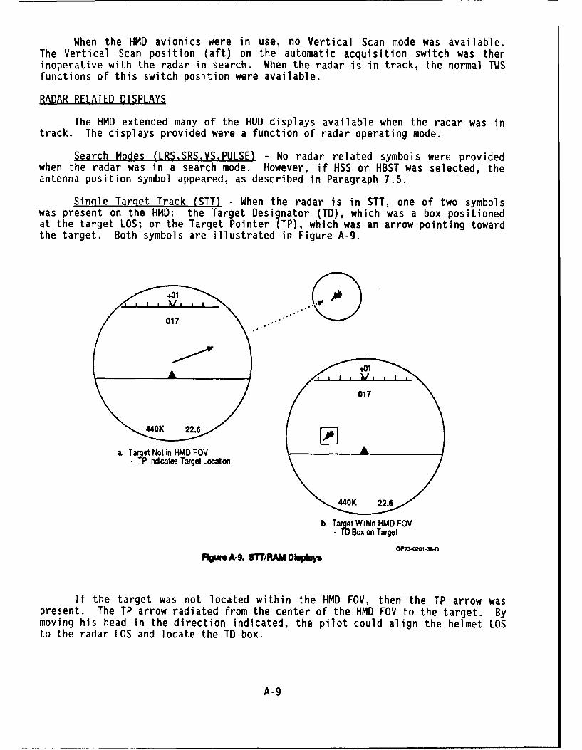
When the HMD avionics were in use, no Vertical Scan mode was available.The Vertical Scan position (aft) on the automatic acquisition switch was theninoperative with the radar in search. When the radar is in track, the normal TWSfunctions of this switch position were available.
RADAR RELATED DISPLAYS
The HMD extended many of the HUD displays available when the radar was intrack. The displays provided were a function of radar operating mode.
Search Modes (LRS.SRS.VS.PULSE) - No radar related symbols were providedwhen the radar was in a search mode. However, if HSS or HBST was selected, theantenna position symbol appeared, as described in Paragraph 7.5.
Single Target Track (STT) - When the radar is in STT, one of two symbolswas present on the HMD: the Target Designator (TD), which was a box positionedat the target LOS; or the Target Pointer (TP), which was an arrow pointing towardthe target. Both symbols are illustrated in Figure A-9.
a. Ta~etNt in HMD FOV- TP Indicate Target Location
b. Target Witin HMD FOV- TO Box on Target
07"0 .IVO-3A0
Flgum A. SiT/RAM Dislay
If the target was not located within the HMD FOV, then the TP arrow waspresent. The TP arrow radiated from the center of the HMD FOV to the target. Bymoving his head in the direction indicated, the pilot could align the helmet LOSto the radar LOS and locate the TD box.
A-A

The TD box was a square 25 mils on each side. The length of the TP arrowwas fixed at 50 mils until the target was within 45 degrees of the helmet LOS.Then, it shortened at a rate of 1 mil/degree until the target was within the HMDFOV (arrow is approximately 11 mils long). Once the target was within the HMDFOV, the TO box appeared around the target, and the TP arrow disappeared.
The two symbols were mutually exclusive; there was no situation when bothcould be displayed at the same time.
Track While Scan (TWS) - In TWS mode the pilot was provided with multipleTO boxes as shown in Figure A-10. These indicated the position of all trackfiles located within the HMD FOV. The priority designated target (i.e, the"starred" target on the radar display) was indicated by a solid TO box. Allother targets were indicated by a segmented TO box.
Priority Target 017
L J
A l Other Targets
440K 22.6
W'73-0201 -30-0Figure A-1 . TWS Dipley
The TP arrow was used to show the location of the priority designatedtarget whenever it was not within the HMD FOV. The length of the TP arrow wasdetermined in the same manner as described above for STT mode. The TP arrow wasmutually exclusive with the solid TO box.
Raid Assessment Mode (RAM) - In RAM mode, a single TO box was available atthe LOS of the designated target. When this target was outside the HMD FOV, theTP arrow was present to indicate its position. When the target was within theHMD FOV, a solid TO box was provided. Essentially, the STT displays wereprovided with the designated target treated as the "tracked" target. Othertargets detected were displayed only on the VSD not the HMD.
If the RAM-Space mode was selected by designating a space, a singlesegmented TO box was provided at the LOS of the designated space point. The TParrow was displayed when the space point LOS was outside the HMD FOV.
A-10

Symbols ReJect - The pilot could manually declutter the HMD by selecting"Symbols Reject" on the HUD control panel. This eliminated all basic symbologyand inhibited attitude warning. All weapons-related symbology continued tooperate, as shown in Figure A-11. The normal Symbols Reject HUD display alsoresulted. Thus, it was not possible to declutter one while leaving a fulldisplay on the other.
" Shown for Case of Radar in STT, SRM Selected,Seeker Uncaged, Shoot Cue Present
" Other Symbols Available Include Helmet AquisitonCircles, Sequented TD Box, TP Arrow, Break "X,and AAI Reply Symbols
GP7-WO1-35-D
Figure A-1l. Typicl Syftbols Reject
HMD Blankin - The pilot could blank the HMD by pressing and holding theHMD blanking switch on the left throttle. While this switch was depressed, allsymbols were removed from the HMD. Releasing the switch restored HMD symbology.
A-11 *L.S.Government Printing Office: 1991-548-018/20225