HEL East Ltd - globalmethane.org · HEL East Ltd Reserve Assessment , Pump Selection and ... AMM...
36
HEL East Ltd � Reserve Assessment , Pump Selection and � Utilization Sizing for AMM and CMM � EPA/GMI CMM Technical Seminar � UNECE – Best Practice Workshop � Donetsk Ukraine � 21/22 September 2011
Transcript of HEL East Ltd - globalmethane.org · HEL East Ltd Reserve Assessment , Pump Selection and ... AMM...
HEL East Ltd�Reserve Assessment , Pump Selection and�
Utilization Sizing for AMM and CMM�
EPA/GMI CMM Technical Seminar�UNECE – Best Practice Workshop�
Donetsk Ukraine�21/22 September 2011
1
2
3
4
5
6
7
8
Content�� Introduction. AMM and CMM as a separate case�
� Part . AMM reserve assessment
� Part . AMM pump selection
� Part . AMM utilization sizing
� Part . CMM reserve assessment
� Part . CMM pump selection
� Part . CMM utilization sizing
� Part . Genset Discussion
� Part . Conclusions
Introduction�
� Abandoned mine methane (AMM) and coalmine methane
(CMM) have many similarities. They are predominantly the
same source of gas. Both are associated with coalmining.
Both represent a hazard to be removed. Both offer
opportunities to recover income by utilization.
� At the same time the technologies are different and offer
quite different problems, requiring quite different solutions
and strategies to maximize opportunity.
Introduction�
� AMM has a unique advantage in that there are no men in a
mine to keep safe.
� AMM can offer continuous flowrates of high quality gas.
� AMM requires no underground workers, consumables or
husbandry.
� AMM is no longer linked to coal production.
Introduction�
But . . .
� AMM is a finite resource.
� AMM is prone to flooding.
� AMM project pressures can range from –80 kPa to +250 kPa�
� AMM can be spoiled by air leaks .
� AMM reserve evaluation is tricky.
Introduction�
� CMM can be considered sustainable whilst ever coal is being
mined.
� CMM drainage is often a given. Methane must be removed�
from many mines if production targets are to be met.�
� CMM too can offer continuous flowrates of high quality gas.�
� CMM gets all the resource a coalmine has to offer - regarding
infrastructure, manpower and capital.
� CMM reserve is (or should be) easier to determine.
Introduction�
But . . .
� CMM needs constant spend on consumables and manpower.�
� CMM needs constant attention to purity (husbandry).
� CMM is linked to coal production and when it stops - even
temporarily – gas flow falls – and gas quality takes a hit too.
� CMM emission rates can change when switching to different�
seams and also when mining is in virgin ground or not.�
Introduction�
Similarities between AMM and CMM projects are . . .
� Frequent over estimation of reserve potential.
� Frequent lack of design considerations of methane vacuum
plants.
� A common tendency to overestimate the utilization potential
in both AMM and CMM projects.
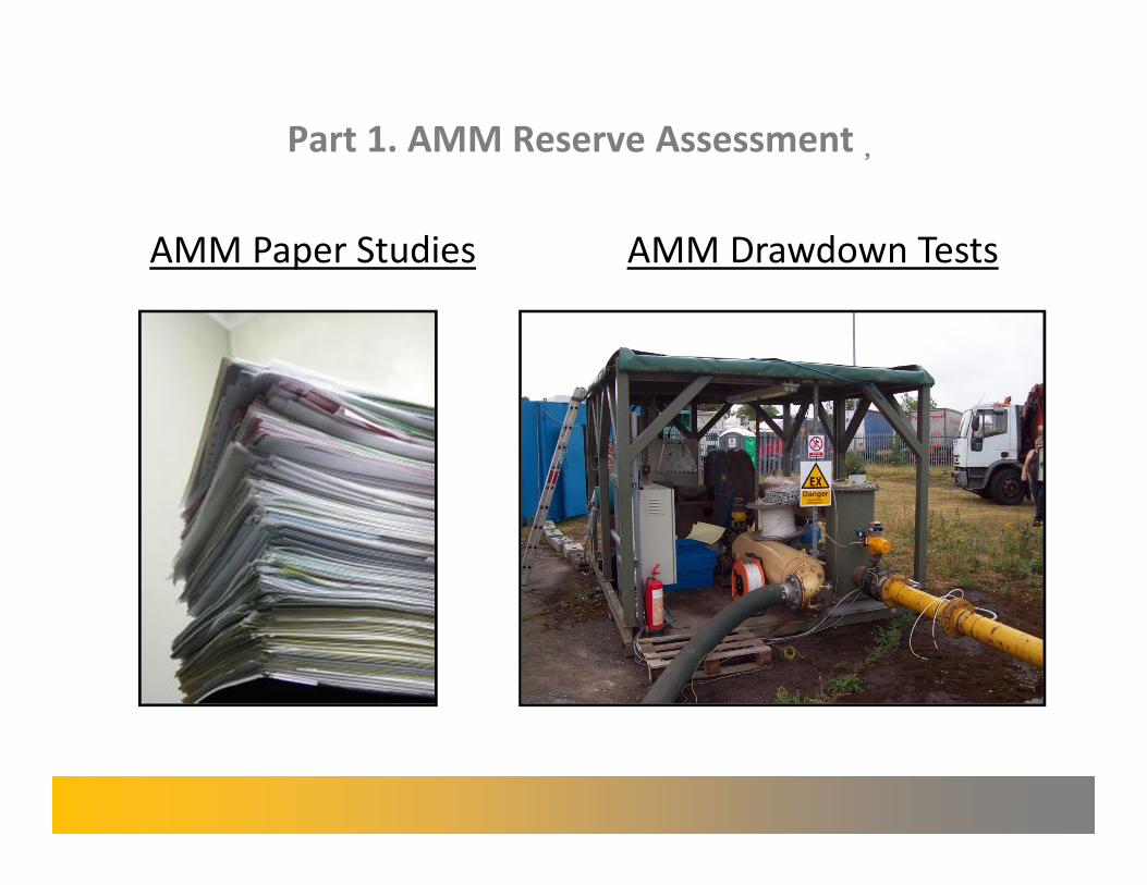
Part 1. AMM Reserve Assessment�
AMM Paper Studies AMM Drawdown Tests�
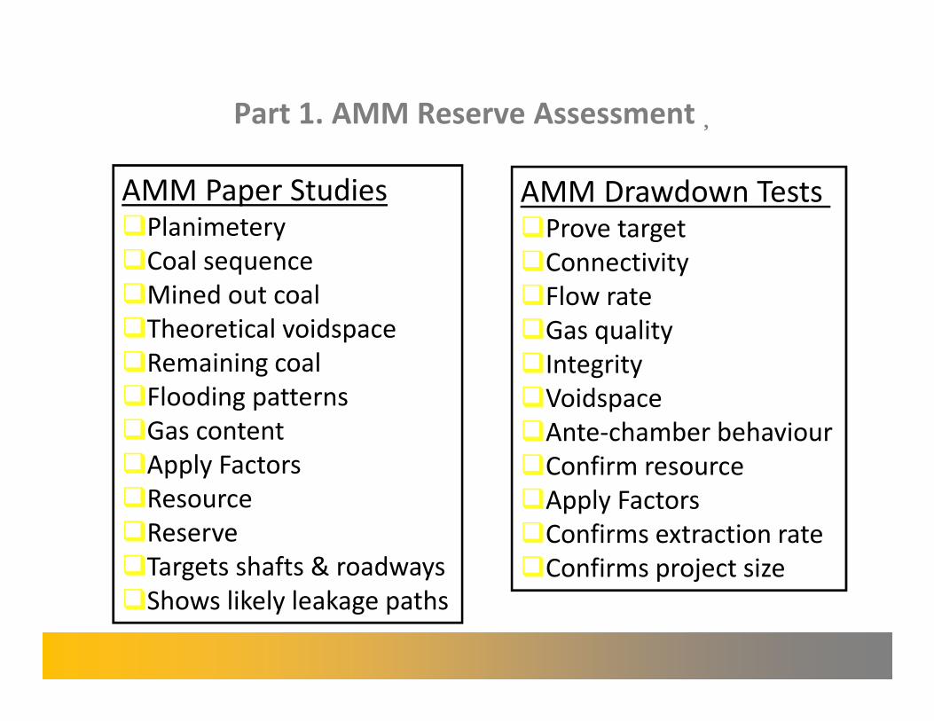
Part 1. AMM Reserve Assessment�
AMM Paper Studies �Planimetery
�Coal sequence
�Mined out coal
�Theoretical voidspace
�Remaining coal
�Flooding patterns
�Gas content
�Apply Factors
�Resource
�Reserve
�Targets shafts & roadways
�Shows likely leakage paths
AMM Drawdown Tests �Prove target
�Connectivity
�Flow rate
�Gas quality
�Integrity
�Voidspace
�Ante-chamber behaviour
�Confirm resource
�Apply Factors
�Confirms extraction rate
�Confirms project size
Part 1. AMM Reserve Assessment�
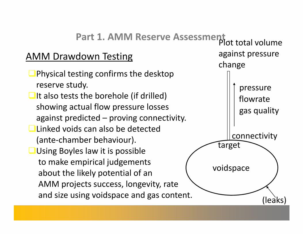
AMM Drawdown Testing
�Physical testing confirms the desktop
reserve study.
�It also tests the borehole (if drilled)
showing actual flow pressure losses
against predicted – proving connectivity.
�Linked voids can also be detected
(ante-chamber behaviour).
�Using Boyles law it is possible
to make empirical judgements
about the likely potential of an
AMM projects success, longevity, rate
and size using voidspace and gas content.
flowrate
connectivity
voidspace
(leaks)
gas quality
target
pressure
Plot total volume
against pressure
change
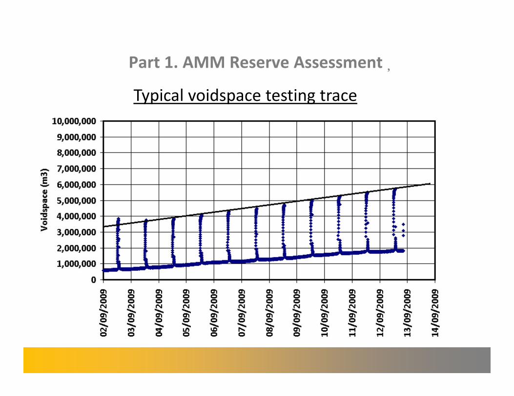
Part 1. AMM Reserve Assessment�
Typical voidspace testing trace

Part 1. AMM Reserve Assessment�
Typical voidspace testing trace
This recovery period illustrates antechamber behaviour (restriction inbye)
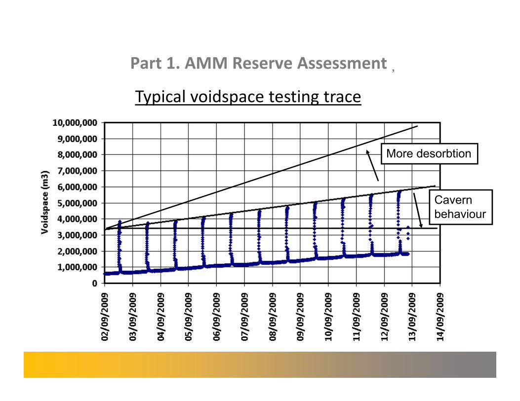
Part 1. AMM Reserve Assessment�
Typical voidspace testing trace
More desorbtion
Cavern behaviour
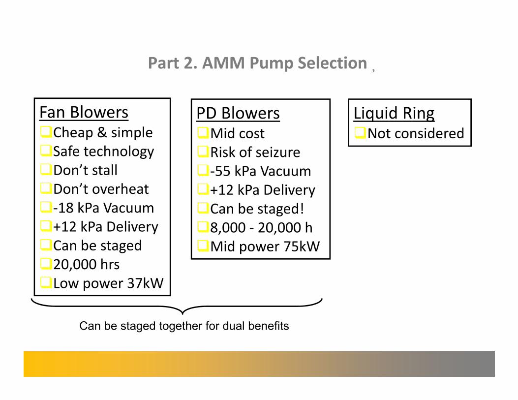
Part 2. AMM Pump Selection�
Fan Blowers �Cheap & simple
�Safe technology
�Don’t stall
�Don’t overheat
�-18 kPa Vacuum
�+12 kPa Delivery
�Can be staged
�20,000 hrs
�Low power 37kW
PD Blowers Liquid Ring �Mid cost �Not considered��Risk of seizure��-55 kPa Vacuum��+12 kPa Delivery��Can be staged!
�8,000 - 20,000 h
�Mid power 75kW
Can be staged together for dual benefits
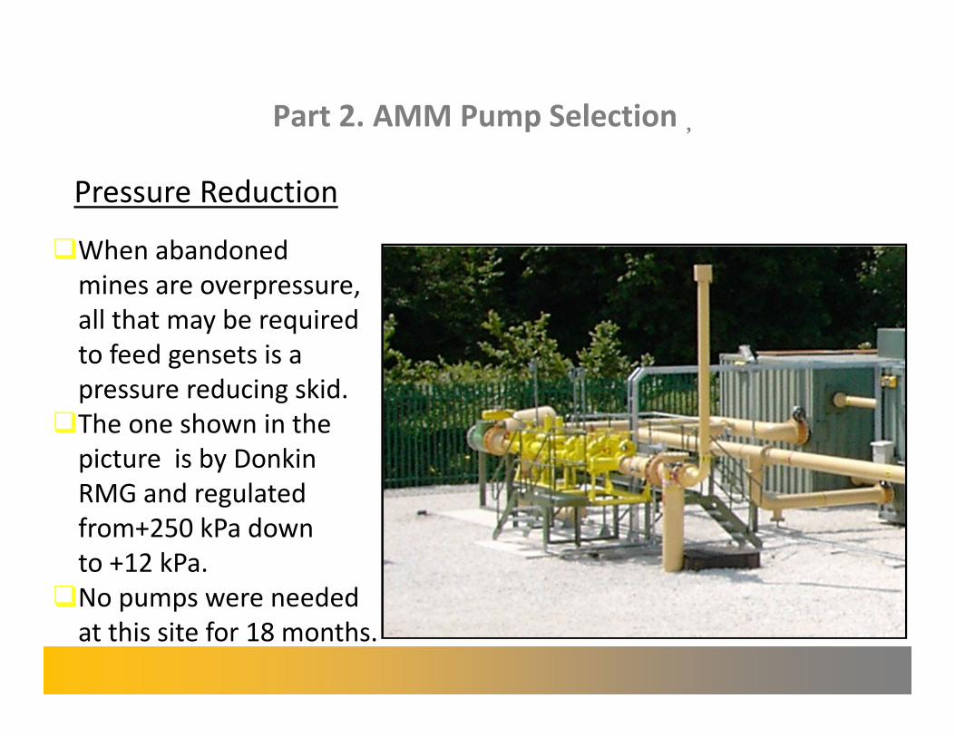
Part 2. AMM Pump Selection�
Pressure Reduction�
�When abandoned
mines are overpressure,
all that may be required
to feed gensets is a
pressure reducing skid.
�The one shown in the
picture is by Donkin
RMG and regulated
from+250 kPa down
to +12 kPa.
�No pumps were needed
at this site for 18 months.
Part 3. AMM Utilization Sizing
Gas Availability and Gas Quality �Abandoned mine methane projects have no need to vent
gas. They only pump what is needed for generation. No gas
enters the atmosphere unburned.
�Similarly, they have little short term variation in gas quality
(unless there is an air leak).
�For these reasons, genset total potential can reach >95%,
only stopping for servicing.
�With this in mind, it is important to choose reliable engines
with long service intervals.
Part 3. AMM Utilization Sizing�
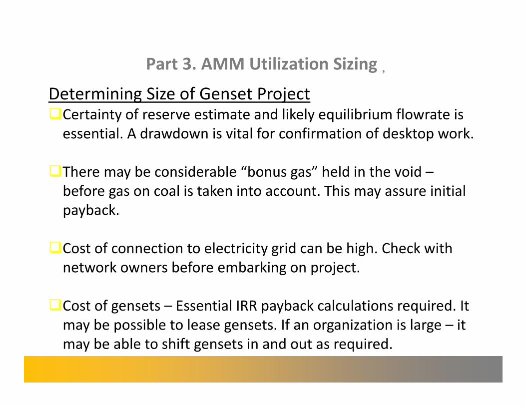
Determining Size of Genset Project �Certainty of reserve estimate and likely equilibrium flowrate is
essential. A drawdown is vital for confirmation of desktop work.
�There may be considerable “bonus gas” held in the void –
before gas on coal is taken into account. This may assure initial
payback.
�Cost of connection to electricity grid can be high. Check with
network owners before embarking on project.
�Cost of gensets – Essential IRR payback calculations required. It
may be possible to lease gensets. If an organization is large – it
may be able to shift gensets in and out as required.
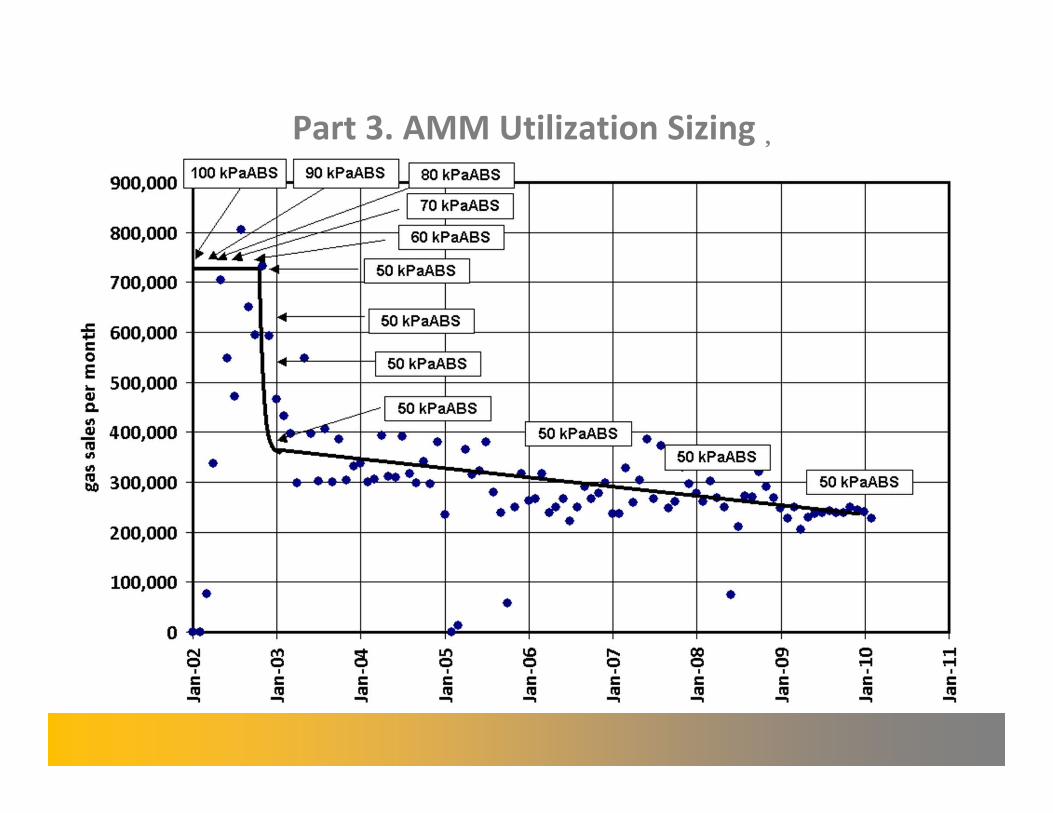
Part 3. AMM Utilization Sizing�
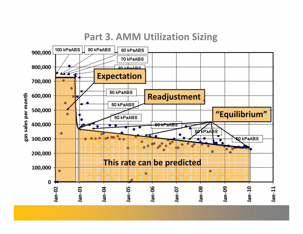
Part 3. AMM Utilization Sizing
Expectation
Readjustment�
“Equilibrium”
This rate can be predicted
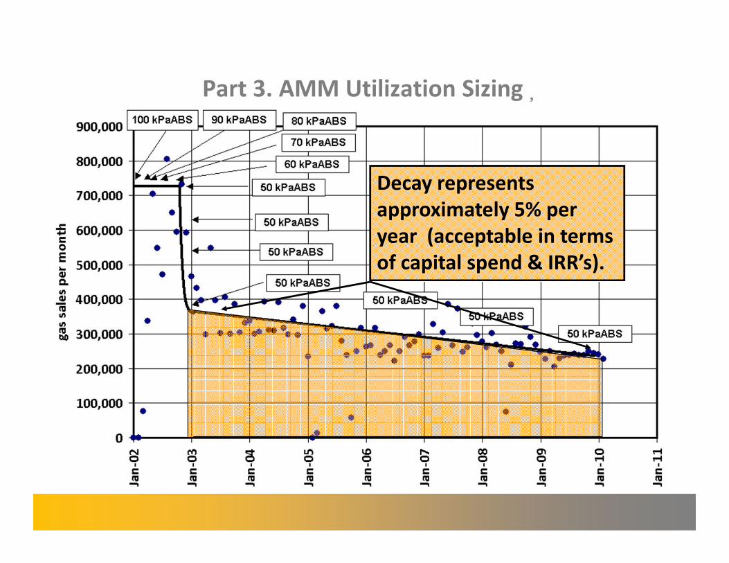
Part 3. AMM Utilization Sizing�
Decay represents
approximately 5% per
year (acceptable in terms
of capital spend & IRR’s).
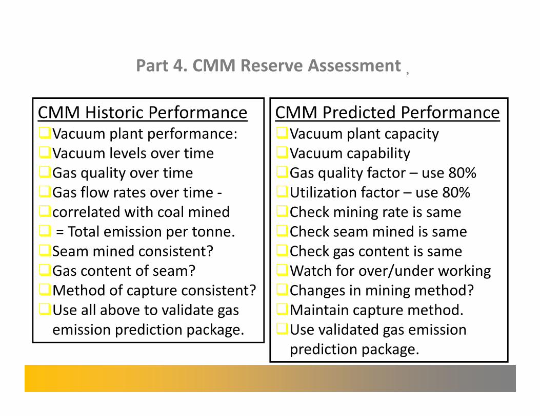
Part 4. CMM Reserve Assessment�
CMM Historic Performance �Vacuum plant performance:
�Vacuum levels over time
�Gas quality over time
�Gas flow rates over time -
�correlated with coal mined
� = Total emission per tonne.
�Seam mined consistent?
�Gas content of seam?
�Method of capture consistent?
�Use all above to validate gas
emission prediction package.
CMM Predicted Performance �Vacuum plant capacity
�Vacuum capability
�Gas quality factor – use 80%
�Utilization factor – use 80%
�Check mining rate is same
�Check seam mined is same
�Check gas content is same
�Watch for over/under working
�Changes in mining method?
�Maintain capture method.
�Use validated gas emission
prediction package.
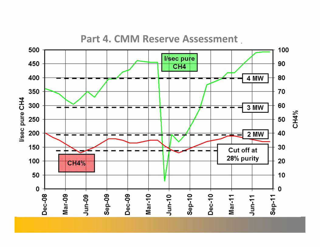
Part 4. CMM Reserve Assessment�
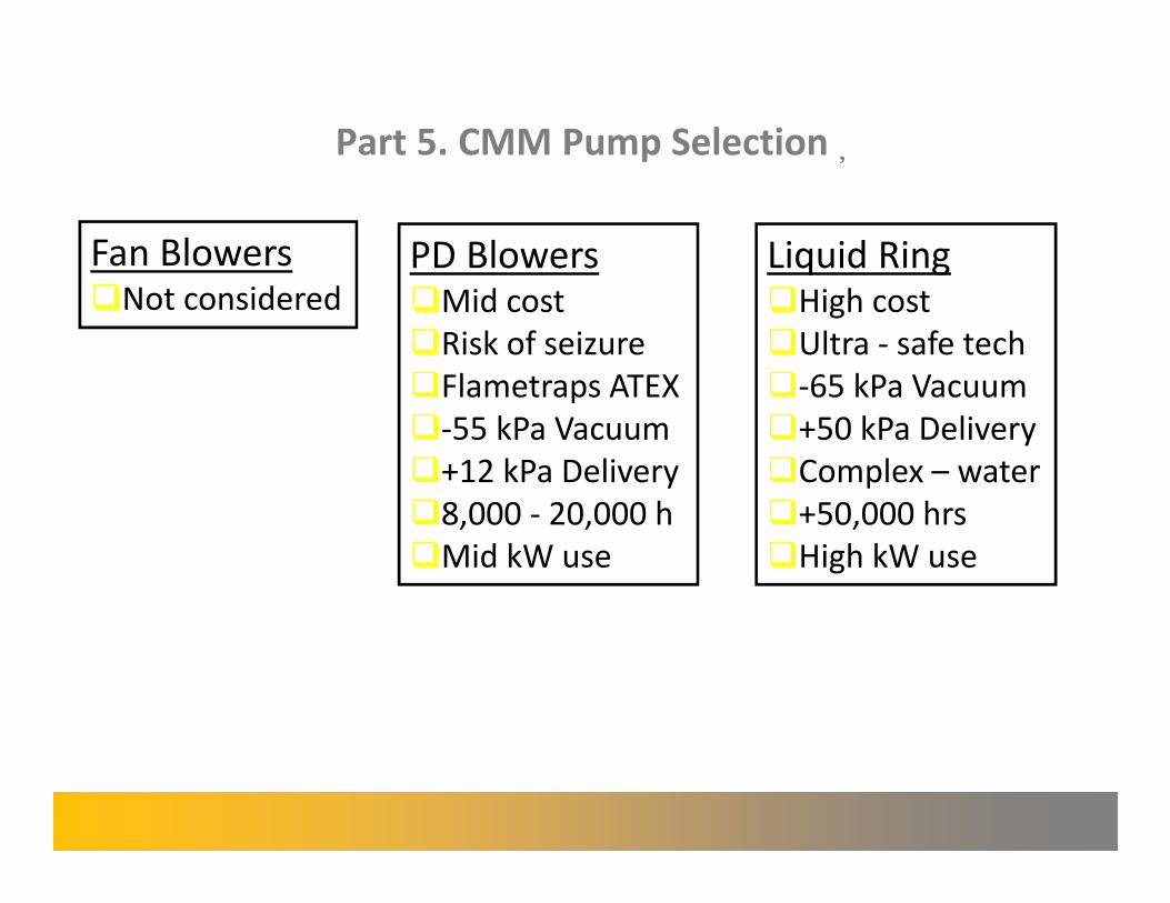
Part 5. CMM Pump Selection�
Fan Blowers �Not considered
PD Blowers Liquid Ring �Mid cost �High cost
�Risk of seizure �Ultra - safe tech��Flametraps ATEX �-65 kPa Vacuum��-55 kPa Vacuum �+50 kPa Delivery��+12 kPa Delivery �Complex – water��8,000 - 20,000 h �+50,000 hrs
�Mid kW use �High kW use
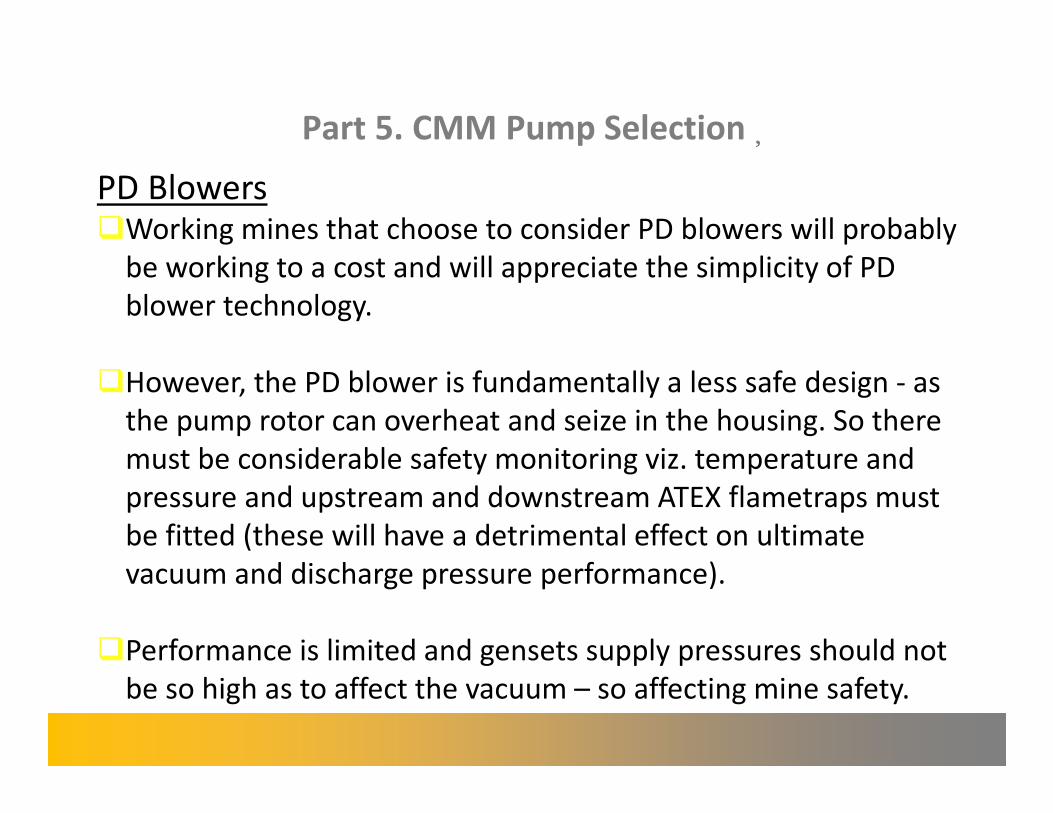
Part 5. CMM Pump Selection�
PD Blowers �Working mines that choose to consider PD blowers will probably
be working to a cost and will appreciate the simplicity of PD
blower technology.
�However, the PD blower is fundamentally a less safe design - as
the pump rotor can overheat and seize in the housing. So there
must be considerable safety monitoring viz. temperature and
pressure and upstream and downstream ATEX flametraps must
be fitted (these will have a detrimental effect on ultimate
vacuum and discharge pressure performance).
�Performance is limited and gensets supply pressures should not�be so high as to affect the vacuum – so affecting mine safety.�
Part 5. CMM Pump Selection�
Liquid Ring �Working mines will generally have an existing methane
extraction plant operating well before utilization is considered.
�They are most commonly liquid ring pumps, fundamentally a
safe design - as the pump rotor is continually bathed in water.
There must be sufficient volume capacity to feed gensets and
“live” spare capacity as swap-outs can be a lengthy procedure.
�Purity can be controlled to a degree - by increasing or
decreasing suction pressure – providing it does not compromise
underground operations. This can be done by altering numbers
of pumps or by modulating a recirculation valve.
Part 6. CMM Utilization Sizing
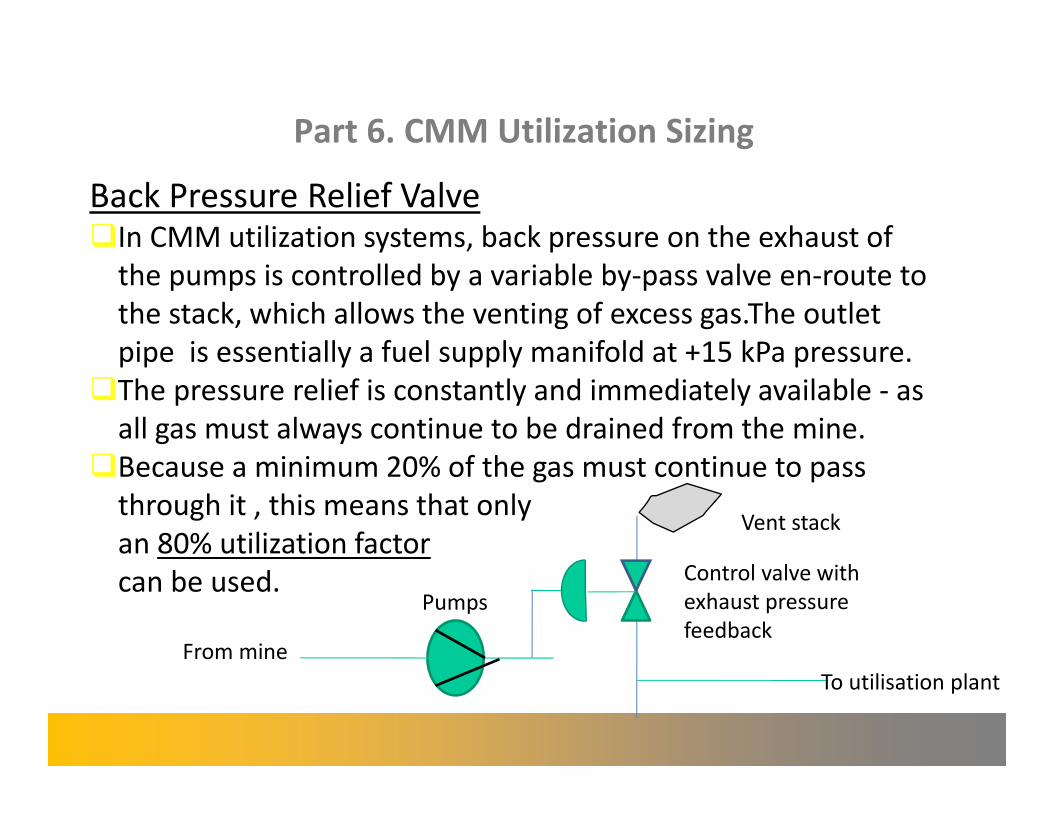
Back Pressure Relief Valve �In CMM utilization systems, back pressure on the exhaust of
the pumps is controlled by a variable by-pass valve en-route to
the stack, which allows the venting of excess gas.The outlet
pipe is essentially a fuel supply manifold at +15 kPa pressure.
�The pressure relief is constantly and immediately available - as
all gas must always continue to be drained from the mine.
�Because a minimum 20% of the gas must continue to pass
through it , this means that only Vent stack
an 80% utilization factor Control valve with can be used. exhaust pressure
feedback
Pumps
From mine
To utilisation plant
Part 6. CMM Utilization Sizing
Gas Availability �In addition, gas quality can be unusable at times , meaning it
is best to apply an 80% availability factor.
�The utilization 80% factor multiplied by the availability 80%
factor means a combined factor of 64% should be applied to
the likely gas reserve flow generation rate potential.
(In practice, this has been borne out in the UK at working mines
where machine generation MWh rates are operating at
between 60% to 65% of the maximum theoretical potential
from of drained gas).
Part 6. CMM Utilization Sizing�
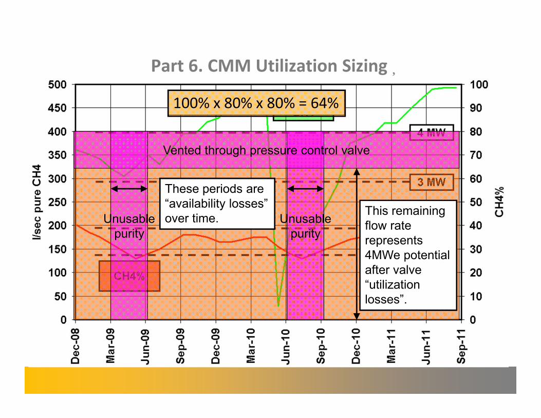
100% x 80% x 80% = 64%�
Vented through pressure control valve
These periods are
Unusable “availability losses”
over time. Unusable This remaining flow rate
purity purity represents 4MWe potential after valve
“utilization
losses”.
Part 6. CMM Utilization Sizing
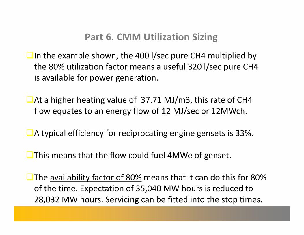
�In the example shown, the 400 l/sec pure CH4 multiplied by
the 80% utilization factor means a useful 320 l/sec pure CH4
is available for power generation.
�At a higher heating value of 37.71 MJ/m3, this rate of CH4�flow equates to an energy flow of 12 MJ/sec or 12MWch.�
�A typical efficiency for reciprocating engine gensets is 33%.
�This means that the flow could fuel 4MWe of genset.
�The availability factor of 80% means that it can do this for 80%
of the time. Expectation of 35,040 MW hours is reduced to
28,032 MW hours. Servicing can be fitted into the stop times.
Part 6. CMM Utilization Sizing�
Size of Utilization Plant �The quantity of gas being drained from the mine will
determine the size of plant.
�A cut-off point will be decided where the energy flow within
the gas is insufficient to deliver payback on the cost of the
smallest divisor of genset modules. IRR modelling can
demonstrate this well.
�Future production schedules may change and providing the
same seam in the same geology is being worked and
providing there is spare capacity in the methane extraction
plant’s volume capacity (and drilling teams can keep pace),
then gas emissions and capture levels should be pro-rata –
leading to a pro rata increase in energy flow. This may be
taken into account when sizing plant for the future.
Part 7. Genset Discussion�
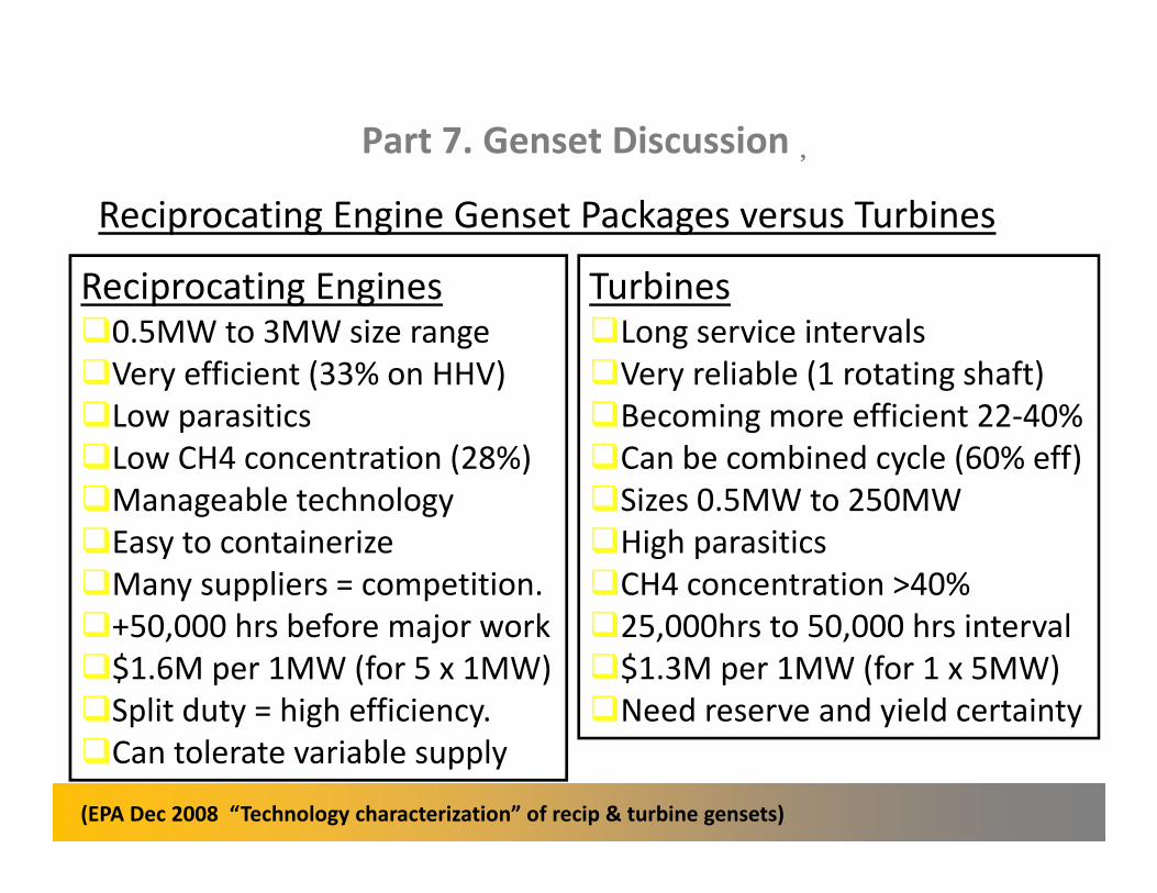
Reciprocating Engine Genset Packages versus Turbines�
Reciprocating Engines Turbines �0.5MW to 3MW size range �Long service intervals
�Very efficient (33% on HHV) �Very reliable (1 rotating shaft)
�Low parasitics �Becoming more efficient 22-40%��Low CH4 concentration (28%) �Can be combined cycle (60% eff)��Manageable technology �Sizes 0.5MW to 250MW
�Easy to containerize �High parasitics
�Many suppliers = competition. �CH4 concentration >40%��+50,000 hrs before major work �25,000hrs to 50,000 hrs interval��$1.6M per 1MW (for 5 x 1MW) �$1.3M per 1MW (for 1 x 5MW)
�Split duty = high efficiency. �Need reserve and yield certainty��Can tolerate variable supply
(EPA Dec 2008 “Technology characterization” of recip & turbine gensets)
Part 7. Genset Discussion�
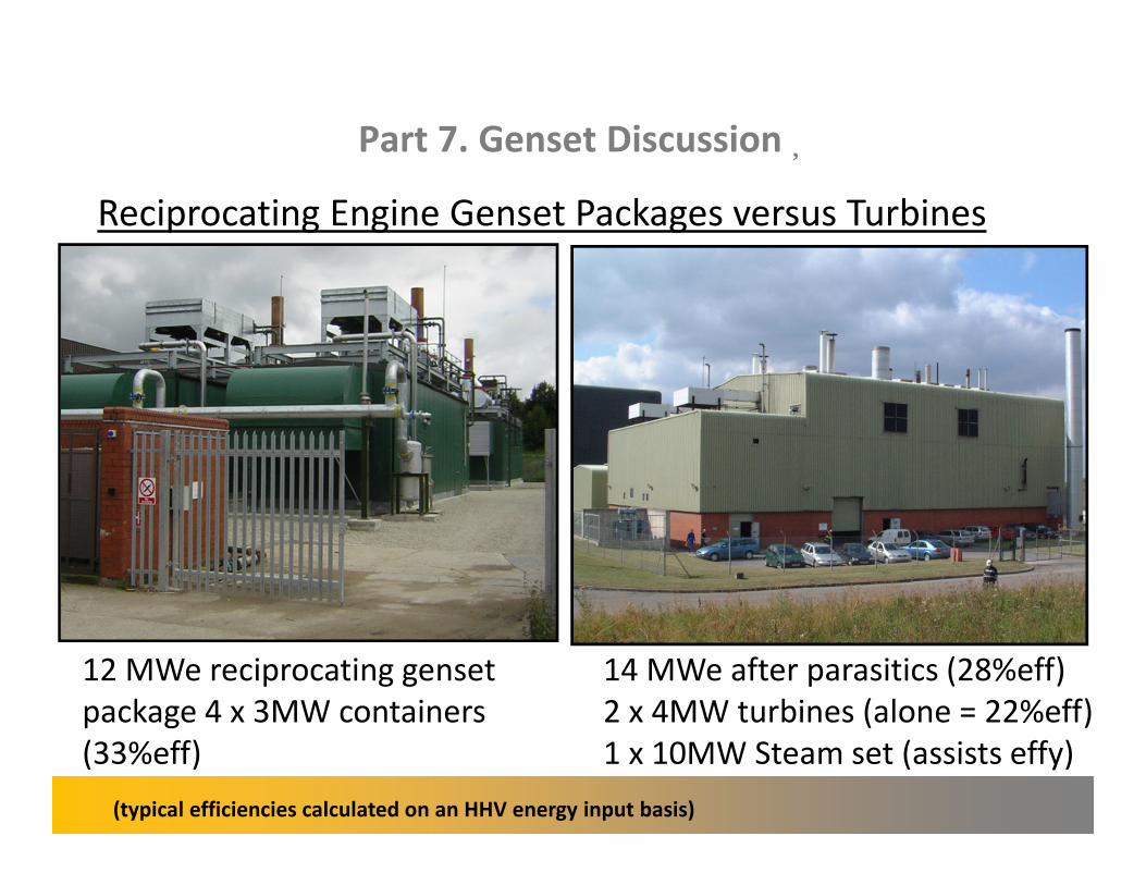
Reciprocating Engine Genset Packages versus Turbines�
12 MWe reciprocating genset 14 MWe after parasitics (28%eff)
package 4 x 3MW containers 2 x 4MW turbines (alone = 22%eff)
(33%eff) 1 x 10MW Steam set (assists effy)
(typical efficiencies calculated on an HHV energy input basis)
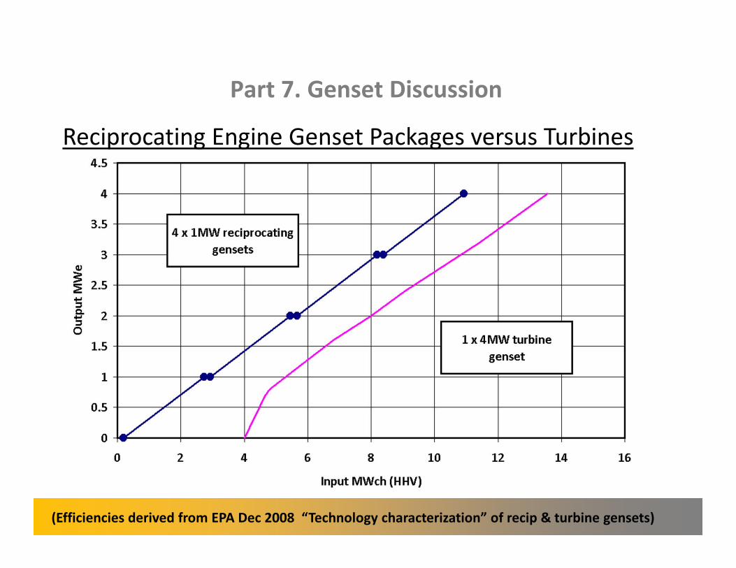
Part 7. Genset Discussion
Reciprocating Engine Genset Packages versus Turbines�
(Efficiencies derived from EPA Dec 2008 “Technology characterization” of recip & turbine gensets)
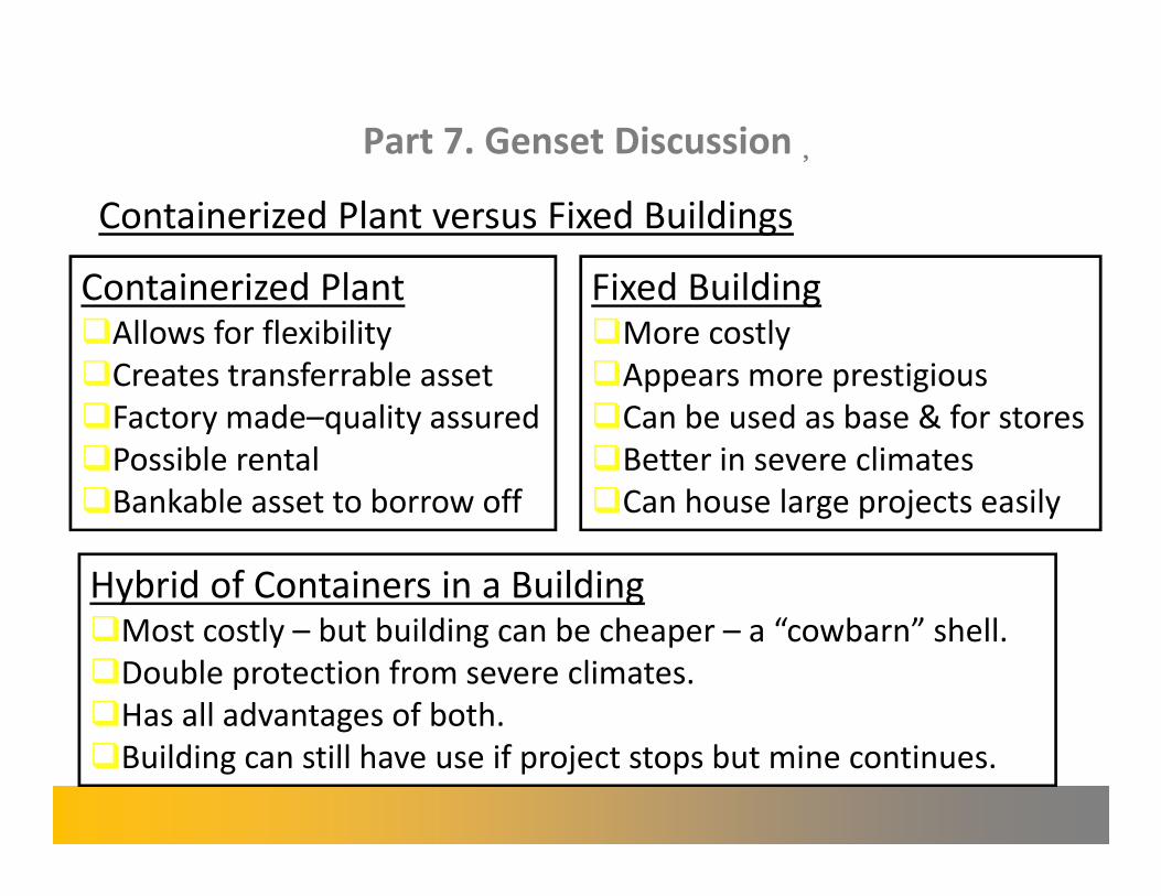
Part 7. Genset Discussion�
Containerized Plant versus Fixed Buildings�
Containerized Plant �Allows for flexibility
�Creates transferrable asset
�Factory made–quality assured
�Possible rental
�Bankable asset to borrow off
Fixed Building �More costly
�Appears more prestigious
�Can be used as base & for stores
�Better in severe climates
�Can house large projects easily
Hybrid of Containers in a Building �Most costly – but building can be cheaper – a “cowbarn” shell.
�Double protection from severe climates.
�Has all advantages of both.
�Building can still have use if project stops but mine continues.

Part 8. Conclusions�
� Choose fan blowers or roots blowers for AMM
� Choose roots blowers or liquid ring pumps for CMM
� AMM utilization projects are frequently oversized so desktop
and drawdown reserve evaluation is essential.
� CMM utilization projects are frequently oversized so historic
trending and future emission prediction is essential.
� CMM utilization projects need 80% availability and 80%�
utilization factors applying to give 64% combined.�
� Containerize and choose multi–recip over single large turbine�