HEAVY INDUSTRY EQUIPMENT CE EVALUATION - … specified by European Union harmonized documents EN...
79
Nemko USA, Inc. 11696 Sorrento Valley Rd., Suite F San Diego, CA 92121-1024 Phone (858) 755-5525 Fax (858) 452-1810 EMC DIRECTIVE 89/336/EEC HEAVY INDUSTRY EQUIPMENT CE EVALUATION TEST REPORT (REVISED) PER EN 61000-6-4, EN 61000-6-2 AND EN 61204-3 For The AC Power Supply MODEL: LZS-A500-3 PREPARED FOR Lambda Electronics 3055 Del Sol Blvd. San Diego, CA 92154 PREPARED ON Oct. 4, 2005 REPORT NUMBER 2005 100857 CE Rev.2 PROJECT NUMBER: 25-857-LAM
Transcript of HEAVY INDUSTRY EQUIPMENT CE EVALUATION - … specified by European Union harmonized documents EN...
Nemko USA, Inc. 11696 Sorrento Valley Rd., Suite F
San Diego, CA 92121-1024 Phone (858) 755-5525 Fax (858) 452-1810
EMC DIRECTIVE 89/336/EEC
HEAVY INDUSTRY EQUIPMENT CE EVALUATION
TEST REPORT (REVISED)
PER EN 61000-6-4, EN 61000-6-2 AND EN 61204-3
For The AC Power Supply
MODEL: LZS-A500-3
PREPARED FOR
Lambda Electronics 3055 Del Sol Blvd. San Diego, CA 92154
PREPARED ON Oct. 4, 2005
REPORT NUMBER 2005 100857 CE Rev.2
PROJECT NUMBER: 25-857-LAM
Nemko USA, Inc. 11696 Sorrento Valley Road, Suite F, San Diego, CA 92121 Phone (858) 755-5525 Fax (858) 452-1810
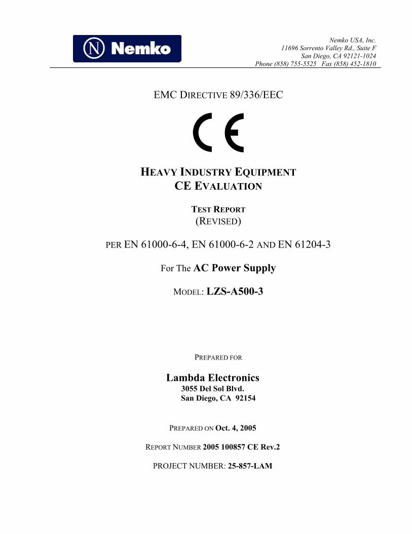
DATE DOCUMENT NAME DOCUMENT # PAGE Oct. 4, 2005 Lambda Electronics - LZS-A500-3 AC Power Supply - CE Evaluation 2005 100857 CE Rev.2 ii of 79
DOCUMENT HISTORY
REVISION DATE COMMENTS
- Oct. 4, 2005 Prepared By: Ferdinand S. Custodio
- Oct. 4, 2005 Initial Release: F.R. Fleury
1 March 16, 2007 Revision Release: Michael T. Krumweide Reason for Revision:
Additional tests for Voltage dips and short interruptions.
2 March 22, 2007 Revision Release: Michael T. Krumweide Reason for Revision:
Correction to Publications dates on page 6.
Restored Test parameters on page 50.
NOTE: Nemko USA, Inc. hereby makes the following statements so as to conform to the Subclause 5.10
Requirements of ISO/IEC 17025 "General Criteria For the Competence Of Testing and Calibration
Laboratories":
o The unit described in this report was received at Nemko USA, Inc.'s facilities on September
29, 2005 . Testing was performed on the unit described in this report on September 29, 2005
to October 4, 2005 .
o The Test Results reported herein apply only to the Unit actually tested, and to substantially
identical Units.
o This report does not imply the endorsement of the Federal Communications Commission
(FCC), NVLAP or any other government agency.
This Report is the property of Nemko USA, Inc., and shall not be reproduced, except in full, without prior
written approval of Nemko USA, Inc. However, all ownership rights are hereby returned unconditionally
to Lambda Electronics, and approval is hereby granted to Lambda Electronics and its employees and
agents to reproduce all or part of this report for any legitimate business purpose without further reference
to Nemko USA, Inc.

Nemko USA, Inc. 11696 Sorrento Valley Road, Suite F, San Diego, CA 92121 Phone (858) 755-5525 Fax (858) 452-1810
DATE DOCUMENT NAME DOCUMENT # PAGE Oct. 4, 2005 Lambda Electronics - LZS-A500-3 AC Power Supply - CE Evaluation 2005 100857 CE Rev.2 iii of 79
TABLE OF CONTENTS DOCUMENT HISTORY.....................................................................................................................................ii
CERTIFICATION ...............................................................................................................................................v
1. ADMINISTRATIVE DATA AND TEST SUMMARY................................................................................1 1.1 Administrative Data ...............................................................................................................................1 1.2 Test Summary.........................................................................................................................................2
2. SYSTEM DESCRIPTION AND CONFIGURATION.................................................................................4 2.1 Description and Method of Exercising the EUT ....................................................................................4 2.2 System Components and Power Cables .................................................................................................4 2.3 Device Interconnection and I/O Cables..................................................................................................4 2.4 Design Modifications for Compliance ...................................................................................................5
3. DESCRIPTION OF TESTING METHODS.................................................................................................6 3.1 Introduction ............................................................................................................................................6 3.2 Configuration and Methods of Measurements for Conducted Emissions ..............................................8 3.3 Configuration and Methods of Measurements for Frequency Identification .......................................10 3.4 Configuration and Methods of Measurements for Radiated Emissions ...............................................12 3.5 Power Line Harmonics: EN 61000-3-2 (2000) ....................................................................................14 3.6 Power Line Fluctuations/Flicker: EN 61000-3-3 (1995)......................................................................14 3.7 Statistical Sampling Required for Continued Compliance...................................................................16 3.8 Device Performance Criteria for Immunity Tests ................................................................................16 3.9 Electrostatic Discharge Immunity: IEC 61000-4-2 (1995) ..................................................................17 3.10 Radio Frequency Immunity: IEC 61000-4-3 (2002) ............................................................................19 3.11 Electrical Fast Transient Immunity: IEC 61000-4-4 (1995) ................................................................21 3.12 Power Line Surge Immunity: IEC 61000-4-5 (1995) ..........................................................................23 3.13 Radio Frequency Conducted Common Mode Immunity: IEC 61000-4-6 (1996)................................25 3.14 Power Frequency Magnetic Field Immunity: IEC 61000-4-8 (1994) ..................................................27 3.15 Voltage Dips and Short Interruptions: IEC 61000-4-11: 2004 ............................................................29
4. TEST RESULTS............................................................................................................................................31 4.1 Conducted Emissions Test Results.......................................................................................................31 4.2 Radiated Emissions Test Results..........................................................................................................33 4.3 Powerline Harmonics Test results ........................................................................................................35 4.4 Powerline Flicker Test Results.............................................................................................................39 4.5 Electrostatic Discharge Immunity Test Results....................................................................................41 4.6 Radio Frequency Immunity Test Results .............................................................................................43 4.7 Electrical Fast Transient Burst Immunity Test Results ........................................................................45 4.8 Power Line Surge Immunity Test Results............................................................................................46 4.9 RF Conducted Common Mode Disturbance Immunity Test Results ...................................................48 4.10 Power Frequency Magnetic Field Immunity Test results.....................................................................49 4.11 Voltage Dips and Short Interruptions Test Results ..............................................................................50

Nemko USA, Inc. 11696 Sorrento Valley Road, Suite F, San Diego, CA 92121 Phone (858) 755-5525 Fax (858) 452-1810
DATE DOCUMENT NAME DOCUMENT # PAGE Oct. 4, 2005 Lambda Electronics - LZS-A500-3 AC Power Supply - CE Evaluation 2005 100857 CE Rev.2 iv of 79
TEST SETUP DIAGRAMS
Figure 1. Conducted Emissions Test Setup Diagram .......................................................................................9 Figure 2. Frequency ID of Radiated Emissions Test Setup Diagram............................................................11 Figure 3. Radiated Emissions Test Setup Diagram .......................................................................................13 Figure 4. Harmonics & Flicker Test Setup Diagram.....................................................................................15 Figure 5. ESD Test Setup Diagram ...............................................................................................................18 Figure 6. Radio Frequency Immunity Test Setup Diagram...........................................................................20 Figure 7. EFT Immunity Test Setup Diagram...............................................................................................22 Figure 8. Power Line Surge Immunity Test Setup Diagram .........................................................................24 Figure 9. RF Common Mode Immunity Test Setup Diagram .......................................................................26 Figure 10. Power Frequency Magnetic Field Immunity Test Setup...............................................................28 Figure 11. Voltage Dips and Short Interruptions Test Setup Diagram...........................................................30 Figure 12. ESD Test Points ............................................................................................................................42
TEST CONFIGURATION PHOTOGRAPHS
Photograph 1. General EUT Test Setup Diagram ...........................................................................................7 Photograph 2. Conducted Emissions Test Configuration..............................................................................51 Photograph 3. Radiated Emissions Test Configuration.................................................................................52 Photograph 4. ESD Immunity Test Configuration ........................................................................................53 Photograph 5. Radio Frequency Immunity Test Configuration ....................................................................54 Photograph 6. EFT Immunity Test Configuration.........................................................................................55 Photograph 7. Power Line Surge Immunity Test Configuration...................................................................56 Photograph 8. Power Line Surge (IEEE C62.41) Immunity Test Configuration ..........................................57 Photograph 9. RF Common Mode Immunity Test Configuration.................................................................58 Photograph 10. I/O RF Common Mode Immunity Test Configuration.........................................................59 Photograph 11. Magnetic Field Immunity Test Configuration......................................................................60 Photograph 12. Voltage Dips and Short Interruptions Immunity Test Configuration...................................61 Photograph 13. Powerline Harmonics and Flicker Test Configuration.........................................................62
APPENDICES Conducted & Radiated Emissions Measurement Uncertainties ....................................................................A-1 Nemko USA, Inc.’s Test Equipment & Facilities Calibration Program........................................................B-1 Nemko AS Certification ................................................................................................................................C-1

Nemko USA, Inc. 11696 Sorrento Valley Road, Suite F, San Diego, CA 92121 Phone (858) 755-5525 Fax (858) 452-1810
DATE DOCUMENT NAME DOCUMENT # PAGE Oct. 4, 2005 Lambda Electronics - LZS-A500-3 AC Power Supply - CE Evaluation 2005 100857 CE Rev.2 v of 79
CERTIFICATION
The compatibility testing and this report have been prepared by Nemko USA, Inc., an independent
electromagnetic compatibility consulting and test laboratory.
As specified by European Union harmonized documents EN 61000-6-4, EN 61000-6-2, and EN 61204-3.
The testing and test methods were accomplished in accordance with both the International Electrotechnical
Committee (IEC) publications and European Norms EN 55011 specifications for Industrial, Scientific and
Medical Equipment (ISM).
I certify the data evaluation and equipment configuration herein to be a true and accurate representation of
the sample's immunity and emission characteristics, as of the test date(s), and for the design of the test
sample utilized to compile this report.
F.R. Fleury
Manager of EMC Operations

Nemko USA, Inc. 11696 Sorrento Valley Road, Suite F, San Diego, CA 92121 Phone (858) 755-5525 Fax (858) 452-1810
DATE DOCUMENT NAME DOCUMENT # PAGE Oct. 4, 2005 Lambda Electronics - LZS-A500-3 AC Power Supply - CE Evaluation 2005 100857 CE Rev.2 1 of 79
1. ADMINISTRATIVE DATA AND TEST SUMMARY 1.1 Administrative Data CLIENT: Lambda Electronics
3055 Del Sol Blvd. San Diego, CA 92154 619 628-2832
CONTACT: Lyn Dinoso
DATE (S) OF TEST: September 29, 2005 to October 4, 2005
EQUIPMENT UNDER TEST (EUT): AC Power Supply
Model LZS-A500-3
Condition Upon Receipt Suitable for Test
TEST SPECIFICATIONS: Radio Frequency Emissions and Electromagnetic Immunity
tests in accordance with EN 61000-6-4 and EN 61000-6-2 as follows:
TEST TYPE TECHNICAL DOCUMENT DOCUMENT TITLE
Conducted and Radiated Emissions
EN 55011 (1998) Specification for Limits and Methods of Measurement of Radio Disturbance Characteristics of Industrial, Scientific and Medical (ISM) Radio-Frequency Equipment
Power Line Harmonics Immunity
EN 61000-3-2 (2000) Electromagnetic Compatibility, Limits for Harmonic Current Emissions, Equipment Input Current less than or equal to 16A
Power Line Flicker Immunity
EN 61000-3-3 (1995) Electromagnetic Compatibility, Limitation of Voltage Fluctuations and Flicker In Low-Voltage Supply Systems for Equipment with Rated Current less than or equal to 16A
Electrostatic Discharge Immunity
IEC 61000-4-2 (1995) Electromagnetic Compatibility for Industrial Process Measurement and Control Equipment Electrostatic Discharge Requirements
Radio Frequency Immunity
IEC 61000-4-3 (2002) Electromagnetic Compatibility - Testing and Measurement Techniques - Radiated Radio Frequency Electromagnetic Field Immunity Test
Electrical Fast Transient Burst Immunity
IEC 61000-4-4 (1995) Electromagnetic Compatibility for Industrial Process Measurement and Control Equipment Electrical Fast Transient / Burst Requirements

Nemko USA, Inc. 11696 Sorrento Valley Road, Suite F, San Diego, CA 92121 Phone (858) 755-5525 Fax (858) 452-1810
DATE DOCUMENT NAME DOCUMENT # PAGE Oct. 4, 2005 Lambda Electronics - LZS-A500-3 AC Power Supply - CE Evaluation 2005 100857 CE Rev.2 2 of 79
Test specifications continued:
Power Line Surge Immunity
IEC 61000-4-5 (1995) Electromagnetic Compatibility, Power Line Surge Immunity
RF Common Mode Immunity
IEC 61000-4-6 (1996) Electromagnetic Compatibility - Basic Immunity Standard - Conducted Disturbances Induced By Radio-Frequency Fields - Immunity Test
Power Frequency Magnetic Field
IEC-61000-4-8 (1994) Electromagnetic Compatibility, Testing and Measurement Techniques for Power Frequency Magnetic Field, Immunity Test
Voltage Dips and Short Interruptions Immunity
IEC 61000-4-11: 2004 Electromagnetic Compatibility - Testing and Measurement Techniques - Voltage Dips, Short Interruptions and Voltage Variations Immunity Tests
1.2 Test Summary 1.2.1 Emissions Test Summary
Specification Frequency Range Compliance Status
EN 55022 (1998) Class “B” Conducted Emissions 0.15 MHz – 30 MHz PASS
EN 55022 (1998) Class “B” Radiated Emissions 30 MHz – 1000 MHz PASS
EN 61000-3-2 (2000) -Power Line Harmonics
up to the 40th Harmonic PASS
EN 61000-3-3 (1995) -Power Line Flicker
less than or equal to 4% Maximum Relative Voltage Change; Value of D(T) less than or equal to 3% for
more than 200 Ms
PASS
Nemko USA, Inc. 11696 Sorrento Valley Road, Suite F, San Diego, CA 92121 Phone (858) 755-5525 Fax (858) 452-1810
DATE DOCUMENT NAME DOCUMENT # PAGE Oct. 4, 2005 Lambda Electronics - LZS-A500-3 AC Power Supply - CE Evaluation 2005 100857 CE Rev.2 3 of 79
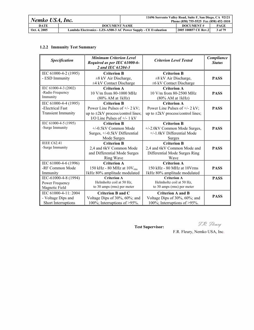
1.2.2 Immunity Test Summary
Specification Minimum Criterion Level Required as per IEC 61000-6-
2 and IEC 61204-3
Criterion Level Tested Compliance Status
IEC 61000-4-2 (1995) - ESD Immunity
Criterion B ±8 kV Air Discharge,
±4 kV Contact Discharge
Criterion B ±8 kV Air Discharge,
±6 kV Contact Discharge
PASS
IEC 61000-4-3 (2002) -Radio Frequency Immunity
Criterion A 10 V/m from 80-1000 MHz
(80% AM at 1kHz)
Criterion A 10 V/m from 80-2500 MHz
(80% AM at 1kHz)
PASS
IEC 61000-4-4 (1995) -Electrical Fast Transient Immunity
Criterion B Power Line Pulses of +/- 2 kV;
up to ±2kV process/control lines;I/O Line Pulses of +/- 1 kV
Criterion A Power Line Pulses of +/- 2 kV;
up to ±2kV process/control lines;
PASS
IEC 61000-4-5 (1995) -Surge Immunity
Criterion B +/-0.5kV Common Mode
Surges, +/-0.5kV Differential Mode Surges
Criterion B +/-2.0kV Common Mode Surges,
+/-1.0kV Differential Mode Surges
PASS
IEEE C62.41 -Surge Immunity
Criterion B 2,4 and 6kV Common Mode and Differential Mode Surges
Ring Wave
Criterion B 2,4 and 6kV Common Mode and Differential Mode Surges Ring
Wave
PASS
IEC 61000-4-6 (1996) -RF Common Mode Immunity
Criterion A 150 kHz - 80 MHz at 10Vrms
1kHz 80% amplitude modulated
Criterion A 150 kHz - 80 MHz at 10Vrms
1kHz 80% amplitude modulated
PASS
IEC-61000-4-8 (1994) Power Frequency Magnetic Field
Criterion A Helmholtz coil at 50 Hz,
to 30 amps (rms) per meter
Criterion A Helmholtz coil at 50 Hz,
to 30 amps (rms) per meter
PASS
IEC 61000-4-11: 2004 - Voltage Dips and Short Interruptions
Criterion B and C Voltage Dips of 30%, 60%; and 100%; Interruptions of >95%.
Criterion A and B Voltage Dips of 30%, 60%; and 100%; Interruptions of >95%.
PASS
Test Supervisor: F.R. Fleury, Nemko USA, Inc.

Nemko USA, Inc. 11696 Sorrento Valley Road, Suite F, San Diego, CA 92121 Phone (858) 755-5525 Fax (858) 452-1810
DATE DOCUMENT NAME DOCUMENT # PAGE Oct. 4, 2005 Lambda Electronics - LZS-A500-3 AC Power Supply - CE Evaluation 2005 100857 CE Rev.2 4 of 79
2. SYSTEM DESCRIPTION AND CONFIGURATION
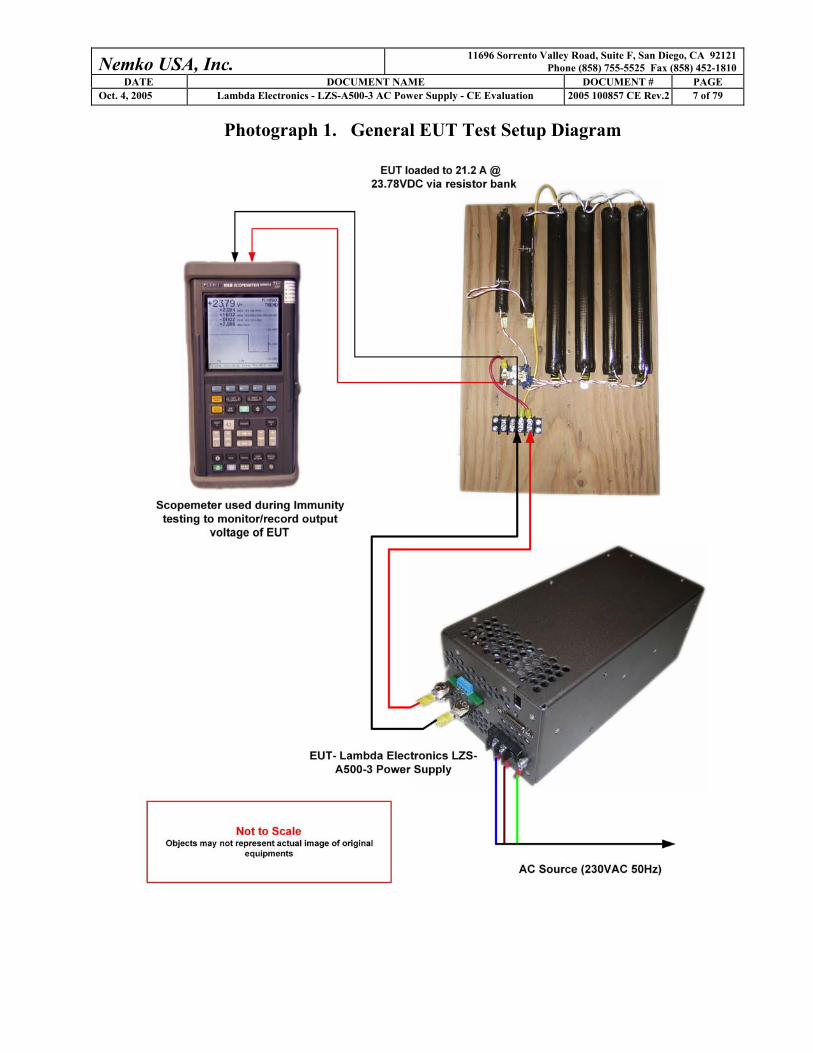
2.1 Description and Method of Exercising the EUT The LZS-A500-3 is a regulated power supply. Its main function is to provide DC power from a single phase
power source. The applications for the EUT include industrial power supply for factory automation, process
control, NC-machining, automotive, packaging equipment, materials handling, chemical processing, robots and
much more. The EUT was exercised by attaching it to a 500W resistive load (24VDC@21A). During Immunity
testing, the output of the EUT will be recorded in real time. Any change in the output voltage will be evaluated
to the corresponding test criteria (+/-1 volt variation) for that particular test.
2.2 System Components and Power Cables
DEVICE
MANUFACTURER
MODEL #
SERIAL #
POWER CABLE
EUT – Regulated Power Supply
Lambda Electronics LZS-A500-3
053920000017
1.8 meters, unshielded, 16AWG x 3, IEC Type
Support Equipment – Load Resistor
Lambda Electronics 1.1Ω total resistance
N/A
Support Equipment – Scopemeter
Fluke 105B Scopemeter Series II
9444 201 05003
Via AC/DC Adapter
Support Equipment – Scopemeter AC/DC Adapter
Fluke PM 8907/803
1697
Direct Wall Plug-In
2.3 Device Interconnection and I/O Cables
CONNECTION I/O CABLE
EUT to Load 1.7 meters, 10AWG x 2, twisted together

Nemko USA, Inc. 11696 Sorrento Valley Road, Suite F, San Diego, CA 92121 Phone (858) 755-5525 Fax (858) 452-1810
DATE DOCUMENT NAME DOCUMENT # PAGE Oct. 4, 2005 Lambda Electronics - LZS-A500-3 AC Power Supply - CE Evaluation 2005 100857 CE Rev.2 5 of 79
2.4 Design Modifications for Compliance
Device: AC Power Supply
Model: LZS-A500-3
The following design modifications were made to the EUT during testing.
Model: Modifications:
LZS-A500-3 Added AMOBEADS* to center leads of D400 & D401.
*Lambda PN TCB00012 manufactured by Toshiba (PN AB3x2x3W - Amorphous Material)
Nemko USA, Inc. recommends a safety review be completed in reference to the above listed design
modification. The purpose of this review is to ensure that no safety issues are introduced as a result of these
design modifications.

Nemko USA, Inc. 11696 Sorrento Valley Road, Suite F, San Diego, CA 92121 Phone (858) 755-5525 Fax (858) 452-1810
DATE DOCUMENT NAME DOCUMENT # PAGE Oct. 4, 2005 Lambda Electronics - LZS-A500-3 AC Power Supply - CE Evaluation 2005 100857 CE Rev.2 6 of 79
3. DESCRIPTION OF TESTING METHODS 3.1 Introduction
Under the EMC Directive 89/336/EEC (as amended by 92/31/EEC) of the European Union (EU), a device is
required to be constructed so that “the electromagnetic disturbance it generates does not exceed a level
allowing radio and telecommunications equipment and other apparatus to operated as intended” and that the
device “has an adequate level of intrinsic immunity of electromagnetic disturbance to enable it to operate as
intended.” The Directive requires that all products brought into service within the EU comply with all
applicable EMC requirements published as harmonized documents known as European Norms (EN). The
harmonized document published for immunity is the EN 61000-6-2:2001, a generic immunity standard for
industrial environments. The harmonized document published for radio frequency emissions is the EN
61000-6-4 (dated January 2001) a generic emissions standard.
The methods employed to test the emissions and immunity characteristics of the Equipment Under Test are
those mandated by the European Standards EN 61000-6-4: 2001 and EN 61000-6-2: 2001. The applicable
tests and the minimum criteria for a pass condition that are listed in the administrative section of this report
are taken from these standards.
For General Test Configuration please refer to Photograph 1 on the following page.
Nemko USA, Inc. 11696 Sorrento Valley Road, Suite F, San Diego, CA 92121 Phone (858) 755-5525 Fax (858) 452-1810
DATE DOCUMENT NAME DOCUMENT # PAGE Oct. 4, 2005 Lambda Electronics - LZS-A500-3 AC Power Supply - CE Evaluation 2005 100857 CE Rev.2 7 of 79
Photograph 1. General EUT Test Setup Diagram
Nemko USA, Inc. 11696 Sorrento Valley Road, Suite F, San Diego, CA 92121 Phone (858) 755-5525 Fax (858) 452-1810
DATE DOCUMENT NAME DOCUMENT # PAGE Oct. 4, 2005 Lambda Electronics - LZS-A500-3 AC Power Supply - CE Evaluation 2005 100857 CE Rev.2 8 of 79
3.2 Configuration and Methods of Measurements for Conducted Emissions
EN 61000-6-4 specifies EN 55011 for the general configuration of the EUT and associated equipment, as well
as the test platform for conducted emissions testing. Floor-standing devices are placed 10 centimeters above a
ground plane floor and 40 centimeters from a vertical ground plane wall. Both quasi-peak and average
detector measurement modes are used. If however, the average limit is met while using a quasi-peak detector,
the test unit is deemed to meet both the limits, and measurement with the average detector receiver is
unnecessary. The quasi-peak and average emission levels are then recorded and compared to the applicable
EN 55011 limits to determine compliance.
EN 61000-6-4 also calls out the requirement for making, where applicable, Discontinuous Disturbance (i.e.,
“Click”) measurements per the limits and methods of Clause 4.2 of EN 55014 (2000). Clause 4.2 of EN
55014 (2000) defines a two part procedure for this. First, a determination is made as to whether or not there
are “clicks” of sufficient magnitude/duration/frequency of occurrence to be subject to limits. Second, and
only if there are “clicks” of sufficient magnitude/duration/frequency of occurrence to be subject to limits, the
“Clicks” are measured and recorded. Otherwise, no “Click” measurements are to be made. “Click”
Disturbances are rarely found to occur in Laboratory Instrumentation; consequently, the requirement is not
usually applicable.
For Conducted Emissions Test Configuration please refer to Figure 1 on the next page.
Nemko USA, Inc. 11696 Sorrento Valley Road, Suite F, San Diego, CA 92121 Phone (858) 755-5525 Fax (858) 452-1810
DATE DOCUMENT NAME DOCUMENT # PAGE Oct. 4, 2005 Lambda Electronics - LZS-A500-3 AC Power Supply - CE Evaluation 2005 100857 CE Rev.2 9 of 79
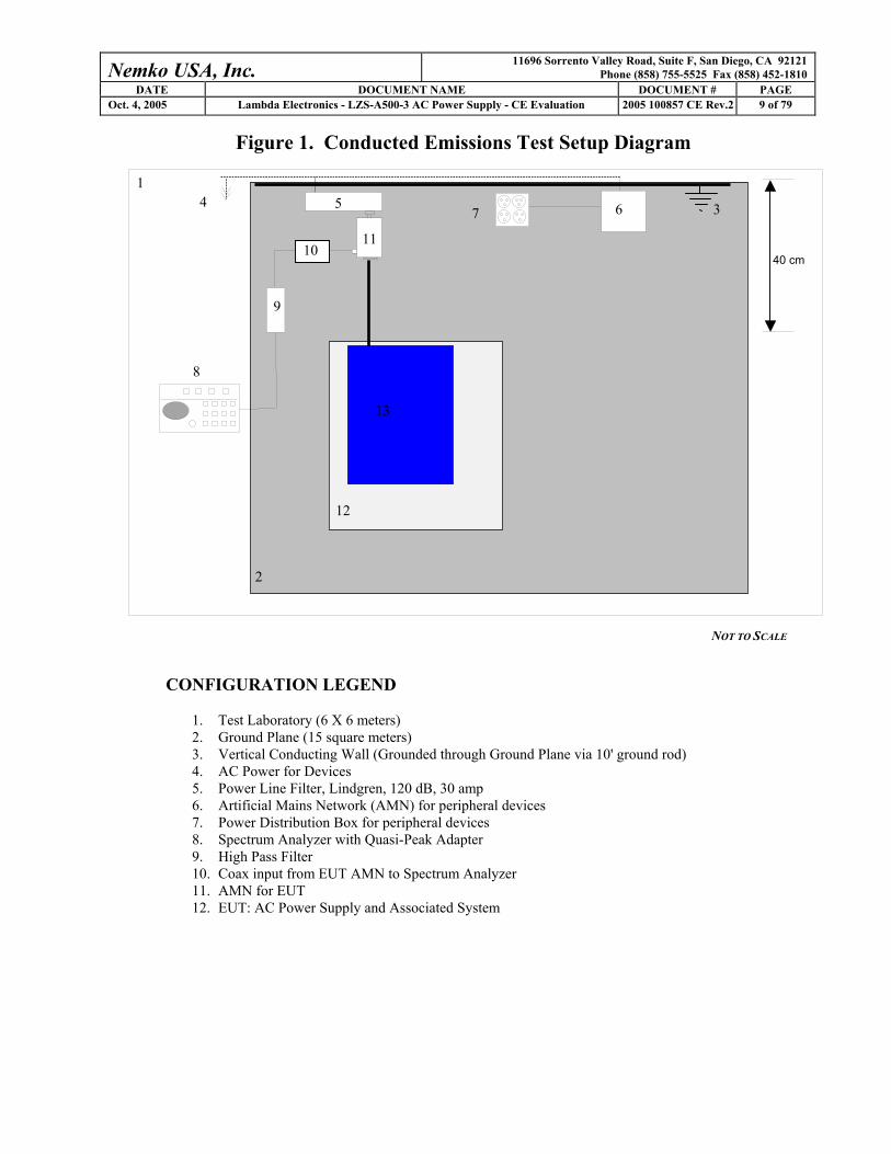
Figure 1. Conducted Emissions Test Setup Diagram
NOT TO SCALE
CONFIGURATION LEGEND
1. Test Laboratory (6 X 6 meters) 2. Ground Plane (15 square meters) 3. Vertical Conducting Wall (Grounded through Ground Plane via 10' ground rod) 4. AC Power for Devices 5. Power Line Filter, Lindgren, 120 dB, 30 amp 6. Artificial Mains Network (AMN) for peripheral devices 7. Power Distribution Box for peripheral devices 8. Spectrum Analyzer with Quasi-Peak Adapter 9. High Pass Filter 10. Coax input from EUT AMN to Spectrum Analyzer 11. AMN for EUT 12. EUT: AC Power Supply and Associated System
8
7
40 cm
9
4 1
2
3 6 5
11
12
13
10
Nemko USA, Inc. 11696 Sorrento Valley Road, Suite F, San Diego, CA 92121 Phone (858) 755-5525 Fax (858) 452-1810
DATE DOCUMENT NAME DOCUMENT # PAGE Oct. 4, 2005 Lambda Electronics - LZS-A500-3 AC Power Supply - CE Evaluation 2005 100857 CE Rev.2 10 of 79
3.3 Configuration and Methods of Measurements for Frequency Identification
When performing all testing of equipment, the actual emissions of the EUT are segregated from ambient
signals present within the laboratory or the open-field test range. Preliminary testing is performed to ensure
that ambient signals are sufficiently low to allow for proper observation of the emissions from the EUT.
Ambients within the laboratory are compared to those noted at the nearby open-field site to discriminate
between signals produced from the EUT and ambient signals. In the event that a significant emission is
produced by the EUT at a frequency that is also demonstrating significant ambient signals, the spectrum
analyzer is placed in the peak mode, the bandwidth is narrowed and the EUT's signal is centered on the
analyzer. The scan width is expanded to 50 kHz while monitoring the audio to ensure that only the EUT
signal is present, the analyzer is switched to quasi-peak mode, and the level of the EUT signal is recorded.
For Frequency ID Test Configuration please refer to Figure 2 on the following page.

Nemko USA, Inc. 11696 Sorrento Valley Road, Suite F, San Diego, CA 92121 Phone (858) 755-5525 Fax (858) 452-1810
DATE DOCUMENT NAME DOCUMENT # PAGE Oct. 4, 2005 Lambda Electronics - LZS-A500-3 AC Power Supply - CE Evaluation 2005 100857 CE Rev.2 11 of 79
Figure 2. Frequency ID of Radiated Emissions Test Setup Diagram
NOT TO SCALE
CONFIGURATION LEGEND 1. Test Laboratory 2. Spectrum Analyzer with Quasi-Peak Adapter 3. Coax interconnect from Antenna to Spectrum Analyzer 4. Receive Antenna (basic relative position) 5. Non-Conducting table 80 cm above ground plane 6. Power strip for EUT and peripherals 7. AC power for devices 8. EUT: AC Power Supply and Associated System
1
8
1m
2 3
4
5
6 7

Nemko USA, Inc. 11696 Sorrento Valley Road, Suite F, San Diego, CA 92121 Phone (858) 755-5525 Fax (858) 452-1810
DATE DOCUMENT NAME DOCUMENT # PAGE Oct. 4, 2005 Lambda Electronics - LZS-A500-3 AC Power Supply - CE Evaluation 2005 100857 CE Rev.2 12 of 79
3.4 Configuration and Methods of Measurements for Radiated Emissions
EN 61000-6-4 specifies EN 55011 for radiated emissions testing. Initially, the primary emission frequencies
are identified inside a shielded anechoic chamber by positioning a broadband receive antenna one meter from
the EUT. Next, the EUT and associated system are placed on a turntable on a ten-meter open area test site
(OATS) with known attenuation characteristics and all significant radiated emissions are recorded. To ensure
that the maximum emission at each discrete frequency of interest is observed, the receive antenna is varied in
height from one to four meters and rotated to produce horizontal and vertical polarities, and the turntable is
also rotated over 360 Degrees to determine the worst emitting configuration. The numerical results of the test
are included herein to demonstrate compliance. The numerical results of the test are included herein to
demonstrate compliance.
The numerical results that are applied to the emissions limits are arrived at by the following method:
Example: A=RR+CL+AF
A = Amplitude dBuV/M
RR = Receiver Reading dBuV
CL = cable loss dB
AF = antenna factor dBm-1
Example Frequency = 110MHz
18.5 dBuV (spectrum analyzer reading)
+3.0 dB (cable loss @ frequency)
21.5 dBuV
+15.4 dBm-1 (antenna factor @ frequency)
36.9 dBuV/M Final adjusted value
The final adjusted value is then compared to the appropriate emission limit to determine compliance.
For Radiated Emissions Test Configuration please refer to Figure 3 on the following page.
Nemko USA, Inc. 11696 Sorrento Valley Road, Suite F, San Diego, CA 92121 Phone (858) 755-5525 Fax (858) 452-1810
DATE DOCUMENT NAME DOCUMENT # PAGE Oct. 4, 2005 Lambda Electronics - LZS-A500-3 AC Power Supply - CE Evaluation 2005 100857 CE Rev.2 13 of 79
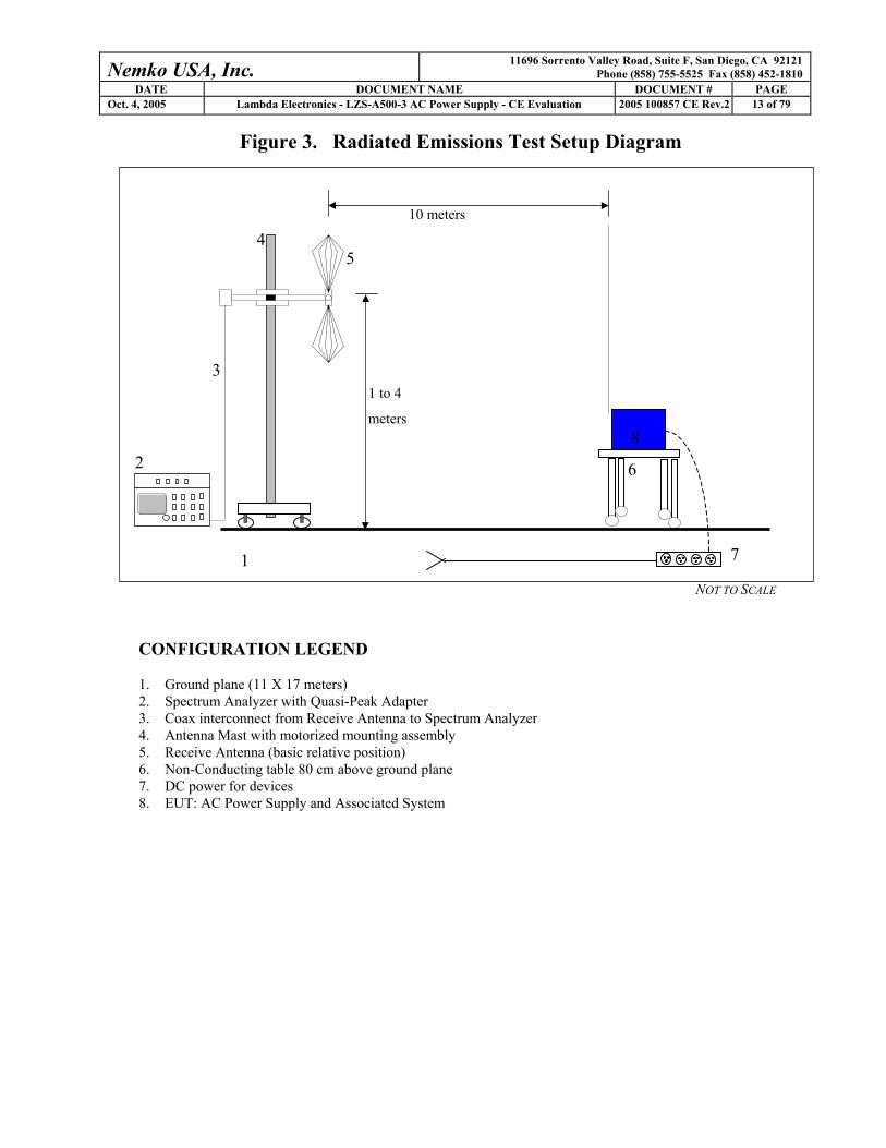
Figure 3. Radiated Emissions Test Setup Diagram
NOT TO SCALE
CONFIGURATION LEGEND 1. Ground plane (11 X 17 meters) 2. Spectrum Analyzer with Quasi-Peak Adapter 3. Coax interconnect from Receive Antenna to Spectrum Analyzer 4. Antenna Mast with motorized mounting assembly 5. Receive Antenna (basic relative position) 6. Non-Conducting table 80 cm above ground plane 7. DC power for devices 8. EUT: AC Power Supply and Associated System
1
2
3
4
1 to 4
meters
10 meters
5
6
7
8

Nemko USA, Inc. 11696 Sorrento Valley Road, Suite F, San Diego, CA 92121 Phone (858) 755-5525 Fax (858) 452-1810
DATE DOCUMENT NAME DOCUMENT # PAGE Oct. 4, 2005 Lambda Electronics - LZS-A500-3 AC Power Supply - CE Evaluation 2005 100857 CE Rev.2 14 of 79
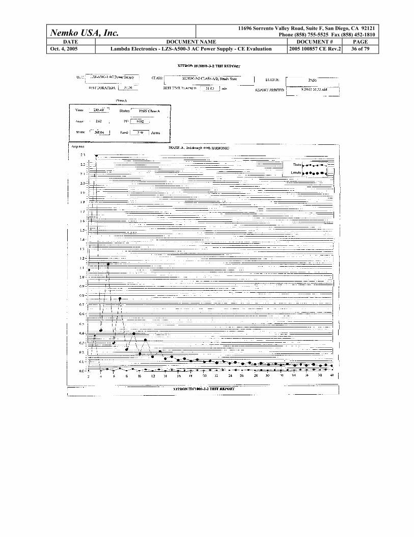
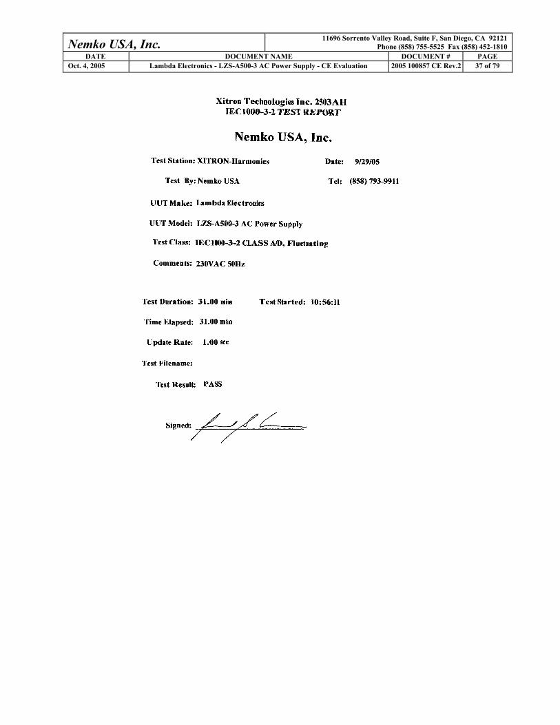
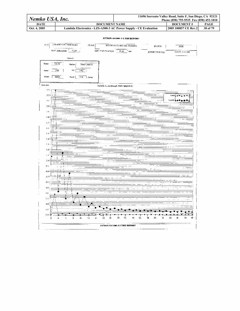
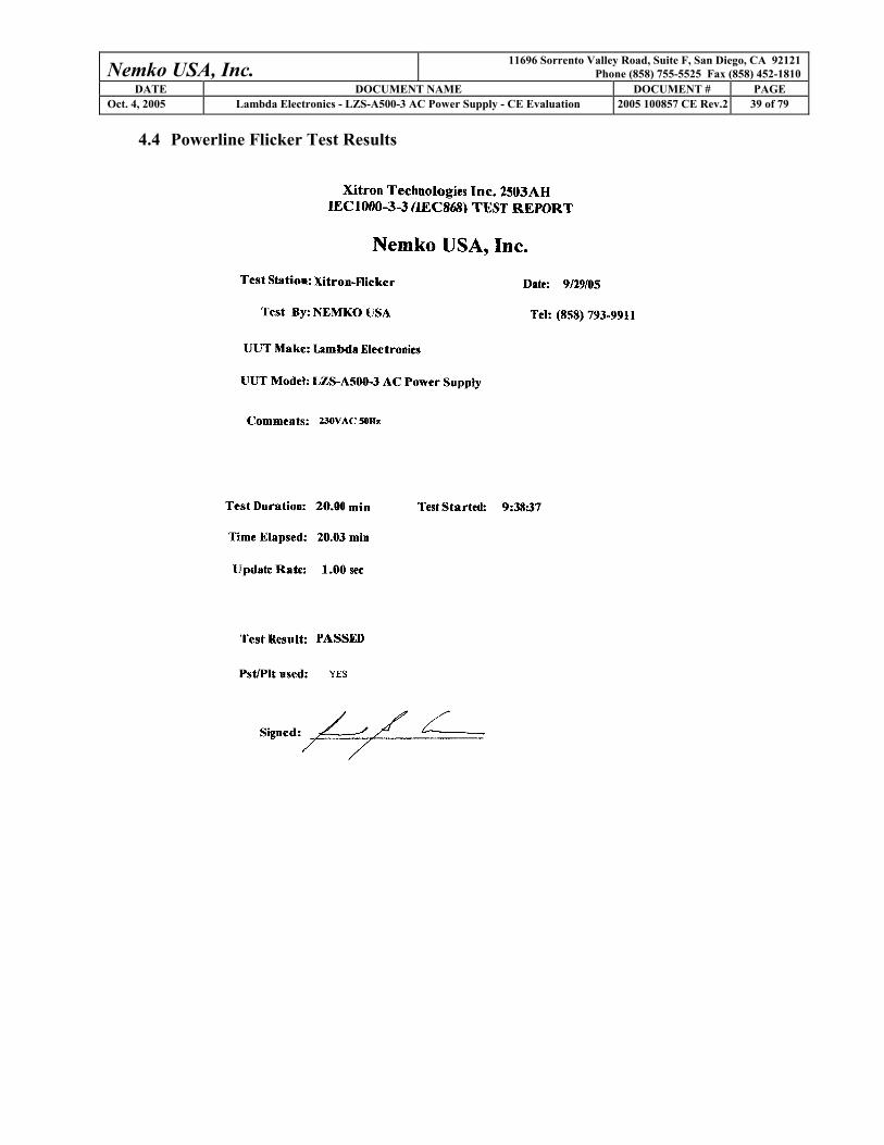
3.5 Power Line Harmonics: EN 61000-3-2 (2000) This section of the EN 61000-3-2 is applicable to electrical and electronic equipment having an input current up to and including 16 amps per phase, and intended to be connected to public low-voltage distribution systems. The objective of this standard is to set limits for harmonic emissions of equipment onto the AC Power Line. Basic requirements of the AC source include a +/- 2% voltage regulation and a +/- 0.5% frequency limit. A low distortion sine wave output is required to ensure that the AC source does not adversely contribute distortion to the load, meeting the following limits: o 0.9% for 3rd order harmonics o 0.4% for 5th order harmonics o 0.3% for 7th order harmonics o 0.2% for 9th order harmonics o 0.2% for even harmonics of order 2 to 10 o 0.1% for odd harmonic order from 11 to 40 For further information, please refer to the technical sections in the EN 61000-3-2 publication (2000) in addition to the test results section and photographs of the test set-up provided in this report. For Harmonics Test Configuration please refer to Figure #4 on the next page. 3.6 Power Line Fluctuations/Flicker: EN 61000-3-3 (1995) This section of the EN 61000-3-3 is applicable to household appliances and similar electrical and electronic equipment having an input current up to and including 16 amps per phase. The objective of this standard is to set limits for voltage fluctuations of equipment within its scope, and ensures that home appliances and certain other electrical equipment do not adversely affect lighting equipment when connected to the same utility power line. Large current variations combined with high utility line power impedance can cause excessive changes in the AC supply voltage. If these voltage changes are repeated at short intervals, objectionable fluctuations of luminance (flicker) could be generated in illumination sources connected to the same utility line network. This test requires an AC power source with a standard impedance network and a power analyzer. Measurements of steady state and fluctuating harmonics, along with flicker and voltage deviations, are conducted using a power analyzer, often called a “flickermeter.” For further information, please refer to the technical sections in the EN 61000-3-3 publication (1995) in addition to the test results section and photographs of the test set-up provided in this report. For Flicker Test Configuration please refer to Figure #4 on the next page.
Nemko USA, Inc. 11696 Sorrento Valley Road, Suite F, San Diego, CA 92121 Phone (858) 755-5525 Fax (858) 452-1810
DATE DOCUMENT NAME DOCUMENT # PAGE Oct. 4, 2005 Lambda Electronics - LZS-A500-3 AC Power Supply - CE Evaluation 2005 100857 CE Rev.2 15 of 79
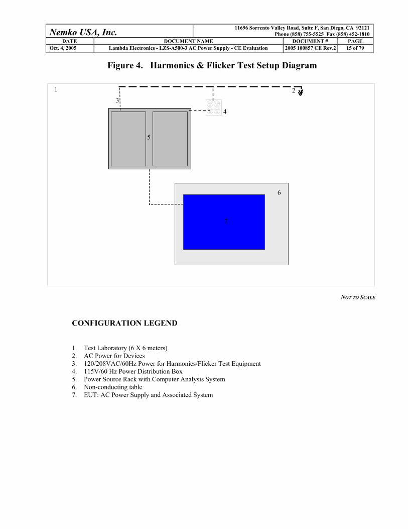
Figure 4. Harmonics & Flicker Test Setup Diagram
NOT TO SCALE
CONFIGURATION LEGEND
1. Test Laboratory (6 X 6 meters) 2. AC Power for Devices 3. 120/208VAC/60Hz Power for Harmonics/Flicker Test Equipment 4. 115V/60 Hz Power Distribution Box 5. Power Source Rack with Computer Analysis System 6. Non-conducting table 7. EUT: AC Power Supply and Associated System
3
4
1 2
6
7
5

Nemko USA, Inc. 11696 Sorrento Valley Road, Suite F, San Diego, CA 92121 Phone (858) 755-5525 Fax (858) 452-1810
DATE DOCUMENT NAME DOCUMENT # PAGE Oct. 4, 2005 Lambda Electronics - LZS-A500-3 AC Power Supply - CE Evaluation 2005 100857 CE Rev.2 16 of 79
3.7 Statistical Sampling Required for Continued Compliance For quality assurance of ongoing productions to comply with RFI interference limits, CISPR 11 Clause 7
stipulates a statistical sampling procedure. In summary, this rule states that the manufacturer should ensure
80% of the units must be in compliance with an 80% confidence level. Refer to CISPR Publication 11,
(1991), Clause 7 for a detailed description of the sampling procedure.
3.8 Device Performance Criteria for Immunity Tests
Equipment tested to EN 61000-6-2 must be evaluated to determine whether or not the “operate as intended”
requirement is met. Three criteria of acceptable performance are defined by EN 61000-6-2, as follows:
o Criterion A - The apparatus shall continue to operate as intended during and after the test. The
manufacturer specifies some minimum performance level, which may be specified by the
manufacturer as a permissible loss of performance.
o Criterion B - The apparatus shall continue to operate as intended after the test. This indicates that
the EUT does not need to function at normal performance levels during the test, but must recover
from any malfunction. Again, the manufacturer defines some minimal performance. No change in
operating state or loss of data is permitted.
o Criterion C - Temporary loss of function is allowed. Operation of the EUT may stop, as long as it
is either automatically reset or can be manually restored by operation of the controls.
For each test method, EN 61000-6-2 specifies the appropriate criterion to be met.
Nemko USA, Inc. 11696 Sorrento Valley Road, Suite F, San Diego, CA 92121 Phone (858) 755-5525 Fax (858) 452-1810
DATE DOCUMENT NAME DOCUMENT # PAGE Oct. 4, 2005 Lambda Electronics - LZS-A500-3 AC Power Supply - CE Evaluation 2005 100857 CE Rev.2 17 of 79
3.9 Electrostatic Discharge Immunity: IEC 61000-4-2 (1995)
EN 61000-6-2 specifies Part 2 of the IEC 61000-4 Standard as the basic procedure for ESD testing. The
standard configuration as outlined in IEC 61000-4-2 (1995) is used. Tabletop devices are placed on an
insulated mat on a horizontal coupling plane. Air discharges and contact charges are made to the EUT on
connectors and conducting surfaces (as illustrated in the Test Results section of this Test Report). For further
information, please refer to the technical sections in the IEC 61000-4-2 (1995) publication in addition to the
test results section and photographs of the test set-up provided in this report.
For ESD tests, EN 61000-6-2 requires that the EUT meet at least performance Criterion B for discharges of up
to ±8 kV air discharge and ±4 kV contact discharge.
For ESD Immunity Test Configuration please refer to Figure 5 on the following page.

Nemko USA, Inc. 11696 Sorrento Valley Road, Suite F, San Diego, CA 92121 Phone (858) 755-5525 Fax (858) 452-1810
DATE DOCUMENT NAME DOCUMENT # PAGE Oct. 4, 2005 Lambda Electronics - LZS-A500-3 AC Power Supply - CE Evaluation 2005 100857 CE Rev.2 18 of 79
Figure 5. ESD Test Setup Diagram
NOT TO SCALE
CONFIGURATION LEGEND 1. Test Laboratory (6 x 7 meters) 2. Vertical Conducting Wall (3 x 3 m, grounded) 3. Ground Plane (14 square meters) 4. Ground Rod extending 3 m under ground plane 5. Non-Conducting table for ESD Simulator Control Box 6. ESD Simulator Control Box on cart 7. Electro-Static Discharge (ESD) Gun (hand held, grounded to grounding rod) 8. DC power for devices 9. Ground strap with two 470kOhm resistors 10. Grounding Strap 11. Horizontal Coupling Plane, grounded to Grounding Rod 12. Insulating Mat 13. Vertical Coupling Plane 14. EUT: AC Power Supply and Associated System
1
2
3
4
6
7
5
8
9
11 12
10
13 14

Nemko USA, Inc. 11696 Sorrento Valley Road, Suite F, San Diego, CA 92121 Phone (858) 755-5525 Fax (858) 452-1810
DATE DOCUMENT NAME DOCUMENT # PAGE Oct. 4, 2005 Lambda Electronics - LZS-A500-3 AC Power Supply - CE Evaluation 2005 100857 CE Rev.2 19 of 79
3.10 Radio Frequency Immunity: IEC 61000-4-3 (2002)
The radio frequency immunity test for a device entails subjecting the device under test to a uniform field of
radiated electromagnetic energy of a specified field strength and frequency, and monitoring the functionality
of the device as the frequency is swept over a specified frequency range. The IEC 61000-4-3 (2002) were
used for radio frequency (RF) immunity requirements and test methods for equipment that are required to
withstand electromagnetic (EM) fields.
The IEC 61000-4-3 (2002) specifies a transmit antenna to EUT distance of 3 m and a frequency range of 80
MHz to 1000 MHz (80% amplitude modulated at 1 kHz). The EUT is set up inside a shielded, semi-anechoic
chamber with a radiating antenna at a distance of 3 meters from the EUT. For further information, please
refer to the technical sections in the IEC 61000-4-3 (2002) publication in addition to the test results section
and photographs of the test set-up provided in this report.
For radio frequency immunity tests, EN 61000-6-2 specifies that the EUT meet performance Criterion A for a
minimum field strength of 10 V/m.
For RF Immunity Test Configuration please refer to Figure 6 on the following page.

Nemko USA, Inc. 11696 Sorrento Valley Road, Suite F, San Diego, CA 92121 Phone (858) 755-5525 Fax (858) 452-1810
DATE DOCUMENT NAME DOCUMENT # PAGE Oct. 4, 2005 Lambda Electronics - LZS-A500-3 AC Power Supply - CE Evaluation 2005 100857 CE Rev.2 20 of 79
Figure 6. Radio Frequency Immunity Test Setup Diagram
NOT TO SCALE
CONFIGURATION LEGEND 1. Test laboratory 2. Shielded anechoic chamber (Anechoic absorber material on walls and ceiling; ferrite tiles on ceiling and floor) 3. Power Line filters and power distribution breaker box 4. Power strip for EUT and peripherals 5. Transmit antennas 6. E-Field sensor 7. Monitoring camera for EUT 8. Broadband power amplifiers 9. E-Field probe monitoring system 10. Signal Generators 11. Non-Conducting table 12. EUT: AC Power Supply and Associated System
1 3
3 m
2 4
5
7 8
9
10
11
12
6

Nemko USA, Inc. 11696 Sorrento Valley Road, Suite F, San Diego, CA 92121 Phone (858) 755-5525 Fax (858) 452-1810
DATE DOCUMENT NAME DOCUMENT # PAGE Oct. 4, 2005 Lambda Electronics - LZS-A500-3 AC Power Supply - CE Evaluation 2005 100857 CE Rev.2 21 of 79
3.11 Electrical Fast Transient Immunity: IEC 61000-4-4 (1995)
EN 61000-6-2 specifies Part 4 of the IEC 61000-4 Standard as the basic procedure for electrical fast transient
testing. IEC 61000-4-4 (1995) defines the immunity requirements and test methods for equipment that are
required to withstand high-voltage transients coupled on the power mains. The standard configuration for
“type tests” outlined in IEC 61000-4-4 (1995) is used. For further information, please refer to the technical
sections in the IEC 61000-4-4 (1995) in addition to the test results section and photographs of the test set-up
provided in this report.
For electrical fast transient/burst tests, EN 61000-6-2 requires that the EUT meet at least performance
Criterion B for +/- 2 kV Power and Process lines and +/- 1 kV signal and data lines transients.
For EFT Immunity Test Configuration please refer to Figure 7 on the following page.
Nemko USA, Inc. 11696 Sorrento Valley Road, Suite F, San Diego, CA 92121 Phone (858) 755-5525 Fax (858) 452-1810
DATE DOCUMENT NAME DOCUMENT # PAGE Oct. 4, 2005 Lambda Electronics - LZS-A500-3 AC Power Supply - CE Evaluation 2005 100857 CE Rev.2 22 of 79
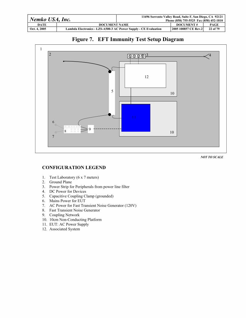
Figure 7. EFT Immunity Test Setup Diagram
NOT TO SCALE
CONFIGURATION LEGEND 1. Test Laboratory (6 x 7 meters) 2. Ground Plane 3. Power Strip for Peripherals from power line filter 4. DC Power for Devices 5. Capacitive Coupling Clamp (grounded) 6. Mains Power for EUT 7. AC Power for Fast Transient Noise Generator (120V) 8. Fast Transient Noise Generator 9. Coupling Network 10. 10cm Non-Conducting Platform 11. EUT: AC Power Supply 12. Associated System
1
10
2 3 4
9 8
6
7
5
11
10
12
Nemko USA, Inc. 11696 Sorrento Valley Road, Suite F, San Diego, CA 92121 Phone (858) 755-5525 Fax (858) 452-1810
DATE DOCUMENT NAME DOCUMENT # PAGE Oct. 4, 2005 Lambda Electronics - LZS-A500-3 AC Power Supply - CE Evaluation 2005 100857 CE Rev.2 23 of 79
3.12 Power Line Surge Immunity: IEC 61000-4-5 (1995)
EN 61000-6-2 specifies Part 5 of the IEC 61000-4 Standard as the basic procedure for power line surge
immunity tests. This standard relates to the immunity requirements, test methods, and range of recommended
test levels for low voltage equipment to unidirectional surges caused by overvoltages from switching and
lightning transients. The standard configuration as outlined in IEC 61000-4-5 (1995), section 7 was used.
Each device was tested in a total of three surge configurations:
Surge #1: Combination Wave, Line to Protective Earth with 9uF and 10Ohm, common mode, generator
earthed. Surge #2: Combination Wave, Neutral to Protective Earth with 9uF and 10Ohm, common mode,
generator earthed. Surge #3: Combination Wave, Line to Neutral with 18uF, differential mode, generator floated.
For further information, please refer to the technical sections in the IEC 61000-4-5 (1995) in addition to the
test results section and photographs of the test set-up provided in this report.
For Power line surge tests, the EUT meet at least performance Criterion B for +/-0.5kV common mode and +/-
0.5kV differential mode surges in the DC power supply configuration.
For Surge Immunity Test Configuration please refer to Figure 8 on the following page.

Nemko USA, Inc. 11696 Sorrento Valley Road, Suite F, San Diego, CA 92121 Phone (858) 755-5525 Fax (858) 452-1810
DATE DOCUMENT NAME DOCUMENT # PAGE Oct. 4, 2005 Lambda Electronics - LZS-A500-3 AC Power Supply - CE Evaluation 2005 100857 CE Rev.2 24 of 79
Figure 8. Power Line Surge Immunity Test Setup Diagram
NOT TO SCALE CONFIGURATION LEGEND 1. Test Laboratory 2. AC power for Devices 3. Power strip for associated devices from power line filter 4. Copper Ground Plane 5. Surge Generator 6. Surge Coupling Network 7. Nonconductive tables 80cm above Ground Plane 8. EUT: AC Power Supply 9. Associated System
3
2
4
7
1
6
5
7
8
9
Nemko USA, Inc. 11696 Sorrento Valley Road, Suite F, San Diego, CA 92121 Phone (858) 755-5525 Fax (858) 452-1810
DATE DOCUMENT NAME DOCUMENT # PAGE Oct. 4, 2005 Lambda Electronics - LZS-A500-3 AC Power Supply - CE Evaluation 2005 100857 CE Rev.2 25 of 79
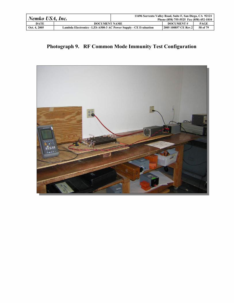
3.13 Radio Frequency Conducted Common Mode Immunity: IEC 61000-4-6 (1996)
EN 61000-6-2 specifies Part 6 of the IEC 61000-4 Standard as the basic standard for radio frequency
conducted common mode disturbance testing. This standard relates to the immunity requirements, test
methods, and range of recommended test levels for immunity to conducted disturbances induced by radio-
frequency fields in the 150 kHz to 80 MHz frequency range. The standard configuration as outlined in the
IEC 61000-4-6 (1996) was used. For further information, please refer to the technical sections of the IEC
61000-4-6 (1996) publication in addition to the test results section and photographs of the test set-up provided
in this report.
For RF induced conducted common mode disturbances, EN 61000-6-2 specifies that the EUT meet at least
performance Criterion B for 10Vrms, 1 kHz, 80% amplitude modulated waveform.
For RF Common Mode Test Configuration please refer to Figure 9 on the following page.
Nemko USA, Inc. 11696 Sorrento Valley Road, Suite F, San Diego, CA 92121 Phone (858) 755-5525 Fax (858) 452-1810
DATE DOCUMENT NAME DOCUMENT # PAGE Oct. 4, 2005 Lambda Electronics - LZS-A500-3 AC Power Supply - CE Evaluation 2005 100857 CE Rev.2 26 of 79
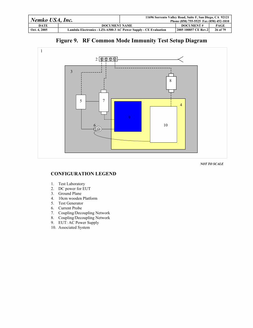
Figure 9. RF Common Mode Immunity Test Setup Diagram
NOT TO SCALE
CONFIGURATION LEGEND 1. Test Laboratory 2. DC power for EUT 3. Ground Plane 4. 10cm wooden Platform 5. Test Generator 6. Current Probe 7. Coupling/Decoupling Network 8. Coupling/Decoupling Network 9. EUT: AC Power Supply 10. Associated System
1
2
9
6
5 7
10
3
4
8
Nemko USA, Inc. 11696 Sorrento Valley Road, Suite F, San Diego, CA 92121 Phone (858) 755-5525 Fax (858) 452-1810
DATE DOCUMENT NAME DOCUMENT # PAGE Oct. 4, 2005 Lambda Electronics - LZS-A500-3 AC Power Supply - CE Evaluation 2005 100857 CE Rev.2 27 of 79
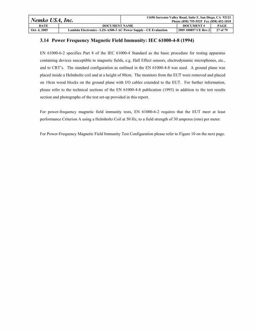
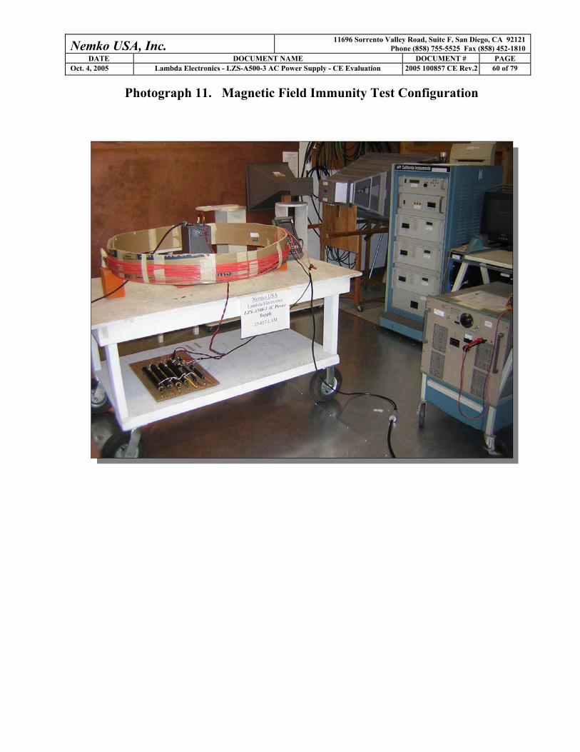
3.14 Power Frequency Magnetic Field Immunity: IEC 61000-4-8 (1994)
EN 61000-6-2 specifies Part 8 of the IEC 61000-4 Standard as the basic procedure for testing apparatus
containing devices susceptible to magnetic fields, e.g. Hall Effect sensors, electrodynamic microphones, etc.,
and to CRT’s. The standard configuration as outlined in the EN 61000-4-8 was used. A ground plane was
placed inside a Helmholtz coil and at a height of 80cm. The monitors from the EUT were removed and placed
on 10cm wood blocks on the ground plane with I/O cables extended to the EUT. For further information,
please refer to the technical sections of the EN 61000-4-8 publication (1993) in addition to the test results
section and photographs of the test set-up provided in this report.
For power-frequency magnetic field immunity tests, EN 61000-6-2 requires that the EUT meet at least
performance Criterion A using a Helmholtz Coil at 50 Hz, to a field strength of 30 amperes (rms) per meter.
For Power-Frequency Magnetic Field Immunity Test Configuration please refer to Figure 10 on the next page.
Nemko USA, Inc. 11696 Sorrento Valley Road, Suite F, San Diego, CA 92121 Phone (858) 755-5525 Fax (858) 452-1810
DATE DOCUMENT NAME DOCUMENT # PAGE Oct. 4, 2005 Lambda Electronics - LZS-A500-3 AC Power Supply - CE Evaluation 2005 100857 CE Rev.2 28 of 79
Figure 10. Power Frequency Magnetic Field Immunity Test Setup
NOT TO SCALE
CONFIGURATION LEGEND
1. Test laboratory 2. AC Power for devices 3. DC Power Supply 4. Helmholtz Coil 5. Ground Plane on Non-Conductive Table 6. EUT: AC Power Supply on 10cm blocks
1
2
3
4
5 6

Nemko USA, Inc. 11696 Sorrento Valley Road, Suite F, San Diego, CA 92121 Phone (858) 755-5525 Fax (858) 452-1810
DATE DOCUMENT NAME DOCUMENT # PAGE Oct. 4, 2005 Lambda Electronics - LZS-A500-3 AC Power Supply - CE Evaluation 2005 100857 CE Rev.2 29 of 79
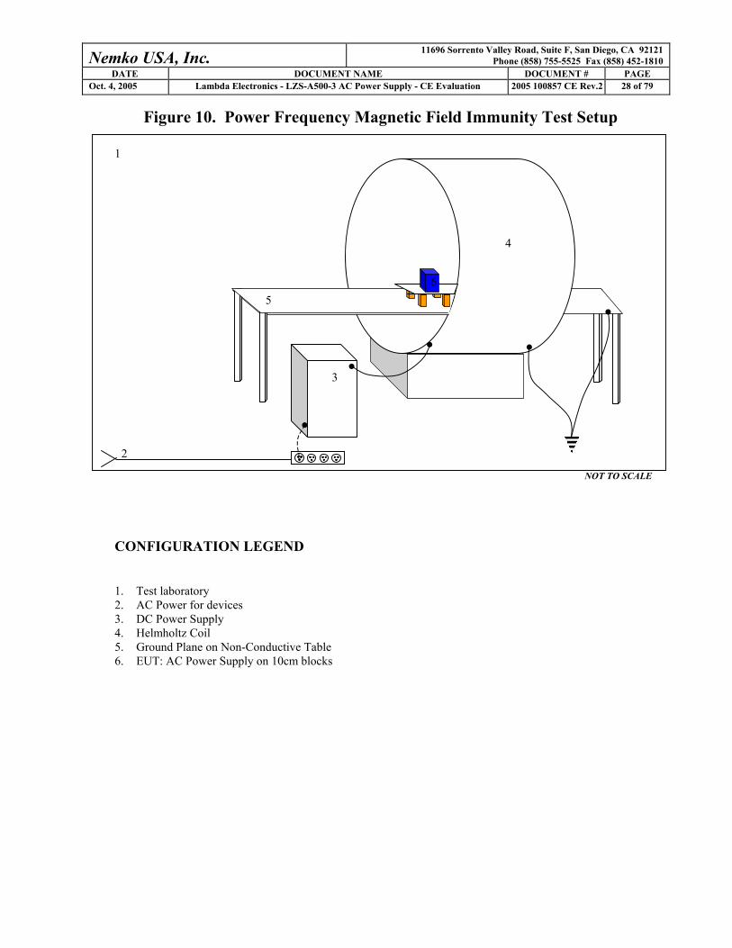
3.15 Voltage Dips and Short Interruptions: IEC 61000-4-11: 2004
EN 61000-6-2 and EN 61204-3 specifies IEC 61000-4-11 Standard as the basic standard for voltage
variations immunity testing. This standard relates to the immunity requirements, test methods, and range of
recommended test levels for immunity to variations in AC line voltage. The standard configuration as
outlined in the IEC 61000-4-11 was used.
For EN 61000-6-2 and EN 61204-3, the EUT was tested to the levels, as required, for those test standards.
The preferred test levels identified in IEC 61000-4-11: 2004 were also applied. Each test level was repeated
three times at 230 VAC at 50 Hz and 120 VAC at 60 Hz.
For further information, please refer to the technical sections of the EN 61000-6-2, EN 61204-3, and IEC
61000-4-11: 2004 publications in addition to the test results section and photographs of the test set-up
provided in this report.
For Voltage Dips Test Configuration please refer to Figure 11 on the following page.
Nemko USA, Inc. 11696 Sorrento Valley Road, Suite F, San Diego, CA 92121 Phone (858) 755-5525 Fax (858) 452-1810
DATE DOCUMENT NAME DOCUMENT # PAGE Oct. 4, 2005 Lambda Electronics - LZS-A500-3 AC Power Supply - CE Evaluation 2005 100857 CE Rev.2 30 of 79
Figure 11. Voltage Dips and Short Interruptions Test Setup Diagram
NOT TO SCALE CONFIGURATION LEGEND 1. Test Laboratory (6 X 6 meters) 2. AC Power for Devices 3. 120/208VAC/60Hz Power for Harmonics/Flicker Test Equipment 4. 115V/60 Hz Power Distribution Box 5. Power Source Rack with Computer Analysis System 6. Non-conducting table 7. EUT: AC Power Supply and Associated System
3
4
1 2
6
7
5

Nemko USA, Inc. 11696 Sorrento Valley Road, Suite F, San Diego, CA 92121 Phone (858) 755-5525 Fax (858) 452-1810
DATE DOCUMENT NAME DOCUMENT # PAGE Oct. 4, 2005 Lambda Electronics - LZS-A500-3 AC Power Supply - CE Evaluation 2005 100857 CE Rev.2 31 of 79
4. TEST RESULTS 4.1 Conducted Emissions Test Results
Client Lambda Electronics Temperature 74 deg F PAN # 25-857-LAM Relative Humidity 48 % EUT Name AC Power Supply Barometric Pressure 30.22 Hg EUT Model LZS-A500-3 Test Location Enclosure 2 Governing Doc EN 61000-6-4 (2001) Test Engineer Ferdinand Custodio
Nemko USA, Inc.EN 55022 Class B Conducted Emissions230VAC @ 50Hz, L1 PK, QP = 0, AV = X
100.0K 1.0M 10.0M 100.0M
Frequency
0
10.0
20.0
30.0
40.0
50.0
60.0
70.0
80.0
90.0
100.0
Am
plitu
de (d
buV)
08:49:33 AM, Thursday, September 29, 2005
Lambda ElectronicsLZS-A500-3 AC Power Supply25-857-LAM
Nemko USA, Inc.EN 55022 Class B Conducted Emissions230VAC @ 50Hz, L2 PK, QP = 0, AV = X
100.0K 1.0M 10.0M 100.0M
Frequency
0
10.0
20.0
30.0
40.0
50.0
60.0
70.0
80.0
90.0
100.0
Am
plitu
de (d
buV)
08:45:50 AM, Thursday, September 29, 2005
Lambda ElectronicsLZS-A500-3 AC Power Supply25-857-LAM

Nemko USA, Inc. 11696 Sorrento Valley Road, Suite F, San Diego, CA 92121 Phone (858) 755-5525 Fax (858) 452-1810
DATE DOCUMENT NAME DOCUMENT # PAGE Oct. 4, 2005 Lambda Electronics - LZS-A500-3 AC Power Supply - CE Evaluation 2005 100857 CE Rev.2 32 of 79
Conducted Emissions Test Equipment
Client Lambda Electronics EUT Name AC Power Supply PAN # 25-857-LAM EUT Model LZS-A500-3
Device Type Model # Asset # Used Cal Done Cal Due
Filter / Limiter High Pass Filter, Solar 8310-1.0 559 X 1/06/05 1/06/06 Transient Limiter, HP 11947A 681 X 5/25/05 5/25/06
Transducer V-Network LISN, Solar 9348-50-R-24-BNC 384 X 3/22/04 3/22/05
Spectrum Analyzer / Receiver Quasi-Peak Adapter, HP Spectrum Analyzer Display, HP Spectrum Analyzer, HP
85650A 85662A 8566B
533 404 104
X 6/24/05 12/24/05

Nemko USA, Inc. 11696 Sorrento Valley Road, Suite F, San Diego, CA 92121 Phone (858) 755-5525 Fax (858) 452-1810
DATE DOCUMENT NAME DOCUMENT # PAGE Oct. 4, 2005 Lambda Electronics - LZS-A500-3 AC Power Supply - CE Evaluation 2005 100857 CE Rev.2 33 of 79
4.2 Radiated Emissions Test Results
San Diego Headquarters:11696 Sorrento Valley Rd.
San Diego, CA 92121Tel: (858) 755-5525
NEMKO USA, Inc. Fax: (858) 452-1810
Radiated Emissions Data
Complete X Job # : 25-857-LAM Test # :Preliminary Page 1 of 1
Client Name : Lambda ElectronicsEUT Name : AC Power supplyEUT Model # : LZS-A500-3 AC EUT Part # : Rev. P2.2EUT Serial # : 53920000017EUT Config. : loaded via resistor bank
Specification : EN55022: 1998, Class B Reference :Rod. Ant. #: NA Temp. (deg. C) : 22 Date : 9/30/2005Bicon Ant.#: 115 Humidity (%) : 35 Time : 8:30AMLog Ant.#: 111 EUT Voltage : 230VAC Staff : FSCustodioDRG Ant. # EUT Frequency : 50Hz Photo ID:Dipole Ant.#: NA Phase: 1 Peak Bandwidth: 120 kHzCable#: NOATS Location: NOATS Video Bandwidth 300 kHzPreamp#: 826 Distance: 10 metersSpec An.#: 898QP #: 898
PreSelect#: NA
Meas. Ant. Atten. Meter Antenna Path RF Corrected Spec. CR/SL PassFreq. Pol. Reading Factor Loss Gain Reading limit Diff. Fail(MHz) (H/V) (dB) (dBuV) (dB) (dB) (dB) (dBuV/m) (dBuV/m) (dB) Unc. Comment40.71 V 37.1 11.7 1.0 32.6 17.2 30.0 -12.8 Pass58.41 V 42.6 12 1.2 32.5 23.3 30.0 -6.7 Pass Ambient72.568 V 40.7 8.3 1.5 32.4 18.1 30.0 -11.9 Pass86.202 V 38.2 7.9 1.7 32.4 15.4 30.0 -14.6 Pass132.1 V 32.4 11.6 2.0 32.6 13.4 30.0 -16.6 Pass139.6 V 31.4 11.8 2.0 32.6 12.6 30.0 -17.4 Pass158.6 V 30.3 13.9 2.1 32.6 13.7 30.0 -16.3 Pass163.3 V 36.3 14.6 2.1 32.7 20.3 30.0 -9.7 Pass182.6 V 38.9 16.7 2.2 32.7 25.1 30.0 -4.9 Pass 30KHz BW (see note)342.4 H 35.1 14.4 3.2 32.9 19.8 37.0 -17.2 Pass364 V 42.9 14.4 3.4 32.9 27.8 37.0 -9.2 Pass
546.3 H 41.6 18.1 4.1 32.6 31.2 37.0 -5.8 Pass
Note: Signal is next to a strong ambient noise, BW changed to isolate signal

Nemko USA, Inc. 11696 Sorrento Valley Road, Suite F, San Diego, CA 92121 Phone (858) 755-5525 Fax (858) 452-1810
DATE DOCUMENT NAME DOCUMENT # PAGE Oct. 4, 2005 Lambda Electronics - LZS-A500-3 AC Power Supply - CE Evaluation 2005 100857 CE Rev.2 34 of 79
Radiated Emissions Test Equipment
Client Lambda Electronics EUT Name AC Power Supply PAN # 25-857-LAM EUT Model LZS-A500-3
Device Type Model # Asset # Used Cal Done Cal Due
Pre-Amplifier Amplifier, Com-Power PA-103 826 X 10/22/04 10/22/05 Antenna OATS #1 (North) Antenna, Biconical EMCO 115 X 2/3/04 2/3/05 Antenna, Log Periodic EMCO 111 X 2/3/04 2/3/05
Spectrum Analyzer / Receiver EMI Receiver, HP RF Filter Section, HP
8546A 85460A
898 899 X 5/16/05 5/16/06
Nemko USA, Inc. 11696 Sorrento Valley Road, Suite F, San Diego, CA 92121 Phone (858) 755-5525 Fax (858) 452-1810
DATE DOCUMENT NAME DOCUMENT # PAGE Oct. 4, 2005 Lambda Electronics - LZS-A500-3 AC Power Supply - CE Evaluation 2005 100857 CE Rev.2 35 of 79
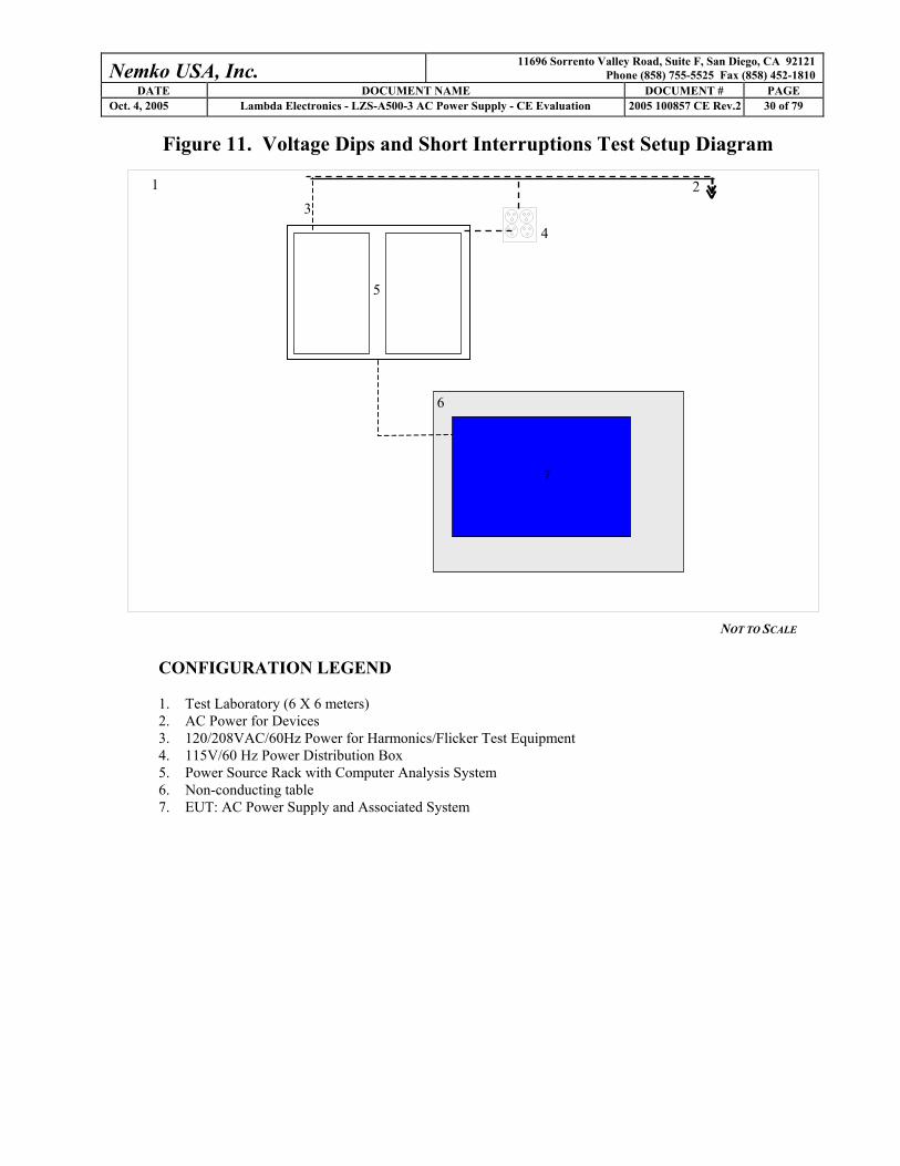
4.3 Powerline Harmonics Test results
Nemko USA, Inc. 11696 Sorrento Valley Road, Suite F, San Diego, CA 92121 Phone (858) 755-5525 Fax (858) 452-1810
DATE DOCUMENT NAME DOCUMENT # PAGE Oct. 4, 2005 Lambda Electronics - LZS-A500-3 AC Power Supply - CE Evaluation 2005 100857 CE Rev.2 36 of 79
Nemko USA, Inc. 11696 Sorrento Valley Road, Suite F, San Diego, CA 92121 Phone (858) 755-5525 Fax (858) 452-1810
DATE DOCUMENT NAME DOCUMENT # PAGE Oct. 4, 2005 Lambda Electronics - LZS-A500-3 AC Power Supply - CE Evaluation 2005 100857 CE Rev.2 37 of 79
Nemko USA, Inc. 11696 Sorrento Valley Road, Suite F, San Diego, CA 92121 Phone (858) 755-5525 Fax (858) 452-1810
DATE DOCUMENT NAME DOCUMENT # PAGE Oct. 4, 2005 Lambda Electronics - LZS-A500-3 AC Power Supply - CE Evaluation 2005 100857 CE Rev.2 38 of 79
Nemko USA, Inc. 11696 Sorrento Valley Road, Suite F, San Diego, CA 92121 Phone (858) 755-5525 Fax (858) 452-1810
DATE DOCUMENT NAME DOCUMENT # PAGE Oct. 4, 2005 Lambda Electronics - LZS-A500-3 AC Power Supply - CE Evaluation 2005 100857 CE Rev.2 39 of 79
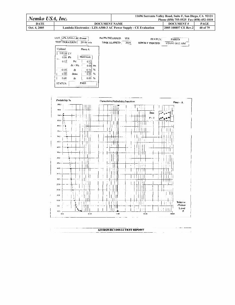
4.4 Powerline Flicker Test Results
Nemko USA, Inc. 11696 Sorrento Valley Road, Suite F, San Diego, CA 92121 Phone (858) 755-5525 Fax (858) 452-1810
DATE DOCUMENT NAME DOCUMENT # PAGE Oct. 4, 2005 Lambda Electronics - LZS-A500-3 AC Power Supply - CE Evaluation 2005 100857 CE Rev.2 40 of 79

Nemko USA, Inc. 11696 Sorrento Valley Road, Suite F, San Diego, CA 92121 Phone (858) 755-5525 Fax (858) 452-1810
DATE DOCUMENT NAME DOCUMENT # PAGE Oct. 4, 2005 Lambda Electronics - LZS-A500-3 AC Power Supply - CE Evaluation 2005 100857 CE Rev.2 41 of 79
4.5 Electrostatic Discharge Immunity Test Results
Client: Lambda Electronics Temperature: 78 degF PAN #: 25-857-LAM Relative Humidity: 50 % EUT Name: AC Power Supply Barometric Pressure: 30.02 Hg EUT Model: LZS-A500-3 Test Location West Ground Plane Governing Doc: EN 61000-6-2 Test Engineer Ferdinand Custodio Basic Standard: IEC 61000-4-2 Date: September 30, 2005 Voltage: 230VAC 50Hz Discharge Rep. Rate X > 1 per second Number of Discharges X > 10 per location
Equipment Used
Device Type Model # Asset # Used Cal Done Cal Due EMC Partner Transient 2000 845 X 8/30/05 2/30/06
Location of Discharge
Contact Discharge Polarity Voltage
(kV) Pos Neg Numbers HCP VCP
2 X X CD# 1 X X 4 X X CD# 1 X X 6 X X CD# 1 X X
Comments: No susceptibility noted. No disruptions on the recorded output of the EUT. Air Discharge
Polarity Voltage (kV) Pos Neg
Numbers
2 X X AD# 1-5 4 X X AD# 1-5 8 X X AD# 1-5
Comments: No susceptibility noted. No disruptions on the recorded output of the EUT. Compliant X Non-Compliant Photo X
Nemko USA, Inc. 11696 Sorrento Valley Road, Suite F, San Diego, CA 92121 Phone (858) 755-5525 Fax (858) 452-1810
DATE DOCUMENT NAME DOCUMENT # PAGE Oct. 4, 2005 Lambda Electronics - LZS-A500-3 AC Power Supply - CE Evaluation 2005 100857 CE Rev.2 42 of 79
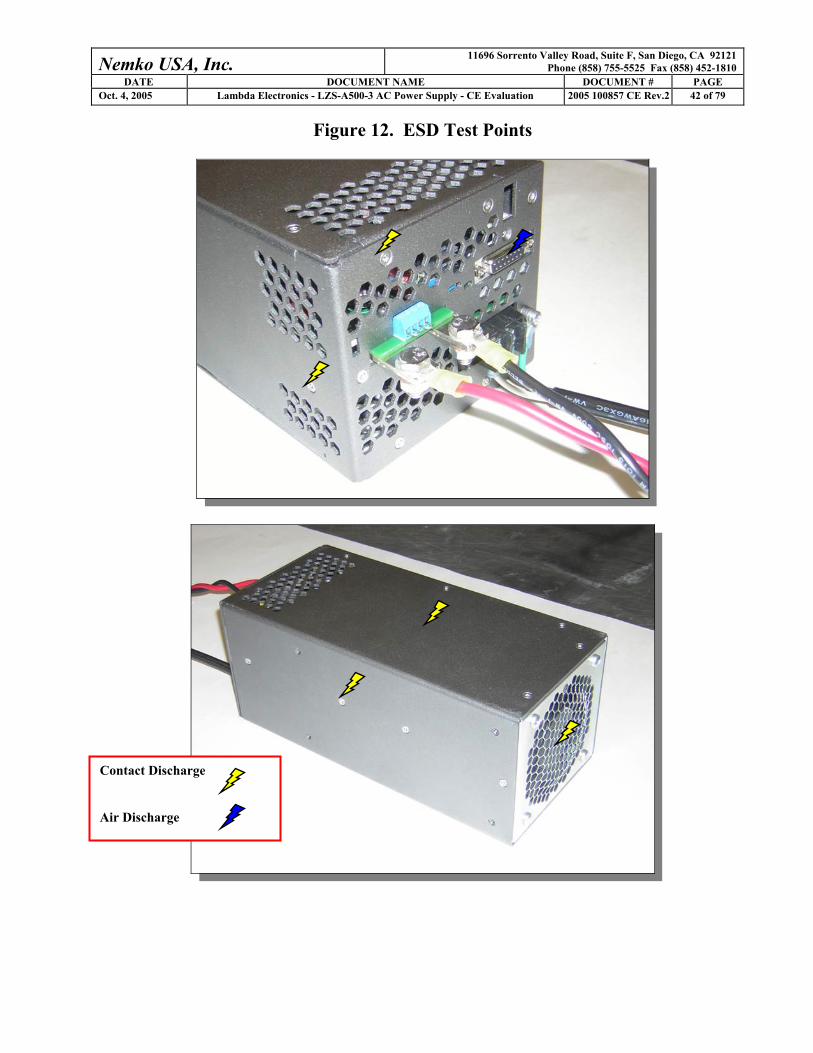
Figure 12. ESD Test Points
Contact Discharge
Air Discharge
Nemko USA, Inc. 11696 Sorrento Valley Road, Suite F, San Diego, CA 92121 Phone (858) 755-5525 Fax (858) 452-1810
DATE DOCUMENT NAME DOCUMENT # PAGE Oct. 4, 2005 Lambda Electronics - LZS-A500-3 AC Power Supply - CE Evaluation 2005 100857 CE Rev.2 43 of 79
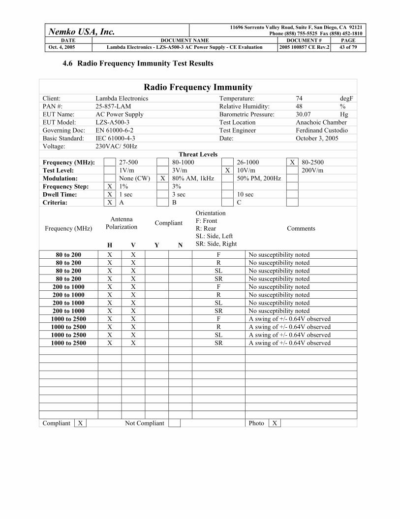
4.6 Radio Frequency Immunity Test Results
Radio Frequency Immunity Client: Lambda Electronics Temperature: 74 degF PAN #: 25-857-LAM Relative Humidity: 48 % EUT Name: AC Power Supply Barometric Pressure: 30.07 Hg EUT Model: LZS-A500-3 Test Location Anachoic Chamber Governing Doc: EN 61000-6-2 Test Engineer Ferdinand Custodio Basic Standard: IEC 61000-4-3 Date: October 3, 2005 Voltage: 230VAC/ 50Hz
Threat Levels Frequency (MHz): 27-500 80-1000 26-1000 X 80-2500 Test Level: 1V/m 3V/m X 10V/m 200V/m Modulation: None (CW) X 80% AM, 1kHz 50% PM, 200Hz Frequency Step: X 1% 3% Dwell Time: X 1 sec 3 sec 10 sec Criteria: X A B C
Antenna Polarization Compliant
Frequency (MHz)
H V Y N
Orientation F: Front R: Rear SL: Side, Left SR: Side, Right
Comments
80 to 200 X X F No susceptibility noted 80 to 200 X X R No susceptibility noted 80 to 200 X X SL No susceptibility noted 80 to 200 X X SR No susceptibility noted
200 to 1000 X X F No susceptibility noted 200 to 1000 X X R No susceptibility noted 200 to 1000 X X SL No susceptibility noted 200 to 1000 X X SR No susceptibility noted
1000 to 2500 X X F A swing of +/- 0.64V observed 1000 to 2500 X X R A swing of +/- 0.64V observed 1000 to 2500 X X SL A swing of +/- 0.64V observed 1000 to 2500 X X SR A swing of +/- 0.64V observed
Compliant X Not Compliant Photo X

Nemko USA, Inc. 11696 Sorrento Valley Road, Suite F, San Diego, CA 92121 Phone (858) 755-5525 Fax (858) 452-1810
DATE DOCUMENT NAME DOCUMENT # PAGE Oct. 4, 2005 Lambda Electronics - LZS-A500-3 AC Power Supply - CE Evaluation 2005 100857 CE Rev.2 44 of 79
Radio Frequency Immunity Test Equipment
Client Lambda Electronics EUT Name AC Power Supply PAN # 25-857-LAM EUT Model LZS-A500-3
Device Type Model # Asset # Used Cal Done Cal Due Signal Generator Gigatronics 1018 440 X 9/22/04 9/22/05 Field Sensors AR FP4080 733 X 3/11/05 3/11/06
Amplifier / Directional Couplers AR 500W1000M5 740 X NCR NCR AR 200T1G3M3 743 X NCR NCR
Antennas Biconical 3109 EA 2466 X NCR NCR Electro-Metrics RGA-30 350 X NCR NCR AR AT4002A 728 X NCR NCR

Nemko USA, Inc. 11696 Sorrento Valley Road, Suite F, San Diego, CA 92121 Phone (858) 755-5525 Fax (858) 452-1810
DATE DOCUMENT NAME DOCUMENT # PAGE Oct. 4, 2005 Lambda Electronics - LZS-A500-3 AC Power Supply - CE Evaluation 2005 100857 CE Rev.2 45 of 79
4.7 Electrical Fast Transient Burst Immunity Test Results
Client Lambda Electronics Temperature 78 deg F PAN # 25-857-LAM Relative Humidity 46 % EUT Name AC Power Supply Barometric Pressure 30.07 Hg EUT Model LZS-A500-3 Test Location West Ground Plane Governing Doc EN 61000-6-2 Test Engineer Ferdinand Custodio Basic Standard IEC 61000-4-4 Date September 29, 2005 Test Level: AC / DC Mains / Control Ports 0.5kV 1.0kV X 2.0kV 4.0kV ______ Signal Ports 0.25kV 0.5kV 1.0kV 2.0kV ______ Test Duration: X 61 sec _______ Test Equipment Asset # Used Calibration Done Calibration Due EMC Partner, Transient 2000 845 X 8/30/05 2/30/06 Performance Criteria: X A B C Direct Injection Output Path
Test Level Polarity (+/-)
L1 L2 PE Comments
2.0 kV +/- X No susceptibility noted 2.0 kV +/- X No susceptibility noted 2.0 kV +/- X No susceptibility noted 2.0 kV +/- X X No susceptibility noted 2.0 kV +/- X X No susceptibility noted 2.0 kV +/- X X No susceptibility noted 2.0 kV +/- X X X No susceptibility noted 0.0 kV +/- Coupling Clamp:
Cable Description (Clamp Injection) Polarity No I/O cable longer than 3 meters
Compliant X Non-Compliant Photo X
Nemko USA, Inc. 11696 Sorrento Valley Road, Suite F, San Diego, CA 92121 Phone (858) 755-5525 Fax (858) 452-1810
DATE DOCUMENT NAME DOCUMENT # PAGE Oct. 4, 2005 Lambda Electronics - LZS-A500-3 AC Power Supply - CE Evaluation 2005 100857 CE Rev.2 46 of 79
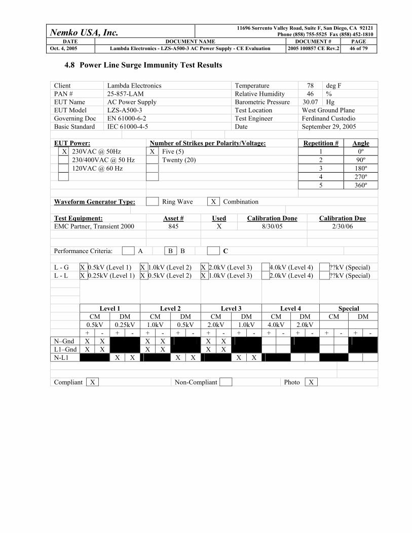
4.8 Power Line Surge Immunity Test Results
Client Lambda Electronics Temperature 78 deg F PAN # 25-857-LAM Relative Humidity 46 % EUT Name AC Power Supply Barometric Pressure 30.07 Hg EUT Model LZS-A500-3 Test Location West Ground Plane Governing Doc EN 61000-6-2 Test Engineer Ferdinand Custodio Basic Standard IEC 61000-4-5 Date September 29, 2005 EUT Power: Number of Strikes per Polarity/Voltage: Repetition # Angle X 230VAC @ 50Hz X Five (5) 1 0º 230/400VAC @ 50 Hz Twenty (20) 2 90º 120VAC @ 60 Hz 3 180º 4 270º 5 360º Waveform Generator Type: Ring Wave X Combination Test Equipment: Asset # Used Calibration Done Calibration Due EMC Partner, Transient 2000 845 X 8/30/05 2/30/06 Performance Criteria: A B B C L - G X 0.5kV (Level 1) X 1.0kV (Level 2) X 2.0kV (Level 3) 4.0kV (Level 4) ??kV (Special) L - L X 0.25kV (Level 1) X 0.5kV (Level 2) X 1.0kV (Level 3) 2.0kV (Level 4) ??kV (Special)
Level 1 Level 2 Level 3 Level 4 Special CM DM CM DM CM DM CM DM CM DM 0.5kV 0.25kV 1.0kV 0.5kV 2.0kV 1.0kV 4.0kV 2.0kV + - + - + - + - + - + - + - + - + - + -
N–Gnd X X X X X X L1–Gnd X X
X X
X X
N-L1 X X X X X X
Compliant X Non-Compliant Photo X
Nemko USA, Inc. 11696 Sorrento Valley Road, Suite F, San Diego, CA 92121 Phone (858) 755-5525 Fax (858) 452-1810
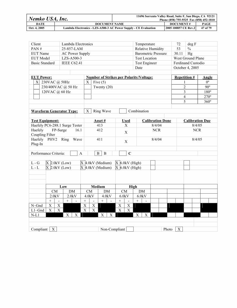
DATE DOCUMENT NAME DOCUMENT # PAGE Oct. 4, 2005 Lambda Electronics - LZS-A500-3 AC Power Supply - CE Evaluation 2005 100857 CE Rev.2 47 of 79
Client Lambda Electronics Temperature 72 deg F PAN # 25-857-LAM Relative Humidity 53 % EUT Name AC Power Supply Barometric Pressure 30.11 Hg EUT Model LZS-A500-3 Test Location West Ground Plane Basic Standard IEEE C62.41 Test Engineer Ferdinand Custodio Date October 4, 2005 EUT Power: Number of Strikes per Polarity/Voltage: Repetition # Angle X 230VAC @ 50Hz X Five (5) 1 0º 230/400VAC @ 50 Hz Twenty (20) 2 90º 120VAC @ 60 Hz 3 180º 4 270º 5 360º Waveform Generator Type: X Ring Wave Combination Test Equipment: Asset # Used Calibration Done Calibration Due Haefely PC6-288.1 Surge Tester 413 X 8/4/04 8/4/05 Haefely FP-Surge 16.1 Coupling Filter
412 X NCR NCR
Haefely PHV2 Ring Wave Plug-In
411 X 8/4/04 8/4/05
Performance Criteria: A B B C L - G X 2.0kV (Low) X 4.0kV (Medium) X 6.0kV (High) L - L X 2.0kV (Low) X 4.0kV (Medium) X 6.0kV (High)
Low Medium High CM DM CM DM CM DM 2.0kV 2.0kV 4.0kV 4.0kV 6.0kV 6.0kV + - + - + - + - + - + -
N–Gnd X X X X X X L1–Gnd X X
X X
X X
N-L1 X X X X X X
Compliant X Non-Compliant Photo X
Nemko USA, Inc. 11696 Sorrento Valley Road, Suite F, San Diego, CA 92121 Phone (858) 755-5525 Fax (858) 452-1810
DATE DOCUMENT NAME DOCUMENT # PAGE Oct. 4, 2005 Lambda Electronics - LZS-A500-3 AC Power Supply - CE Evaluation 2005 100857 CE Rev.2 48 of 79
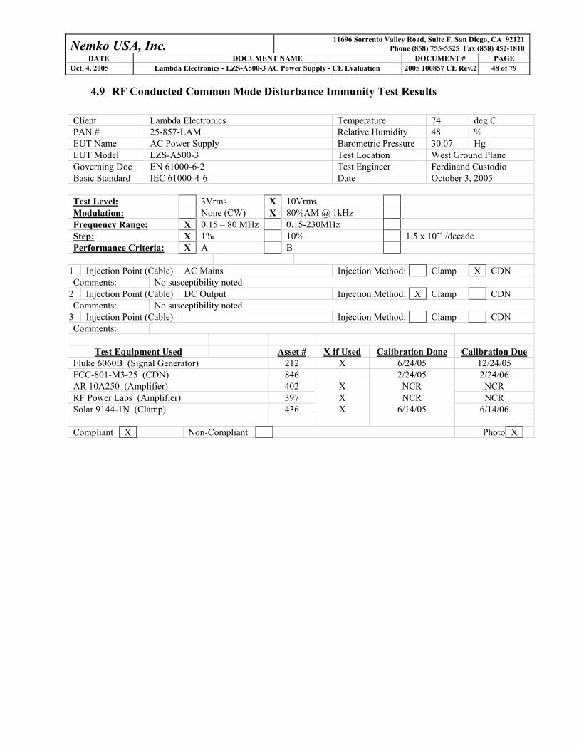
4.9 RF Conducted Common Mode Disturbance Immunity Test Results
Client Lambda Electronics Temperature 74 deg C PAN # 25-857-LAM Relative Humidity 48 % EUT Name AC Power Supply Barometric Pressure 30.07 Hg EUT Model LZS-A500-3 Test Location West Ground Plane Governing Doc EN 61000-6-2 Test Engineer Ferdinand Custodio Basic Standard IEC 61000-4-6 Date October 3, 2005 Test Level: 3Vrms X 10Vrms Modulation: None (CW) X 80%AM @ 1kHz Frequency Range: X 0.15 – 80 MHz 0.15-230MHz Step: X 1% 10% 1.5 x 10¯³ /decade Performance Criteria: X A B
1 Injection Point (Cable) AC Mains Injection Method: Clamp X CDN Comments: No susceptibility noted
2 Injection Point (Cable) DC Output Injection Method: X Clamp CDN Comments: No susceptibility noted
3 Injection Point (Cable) Injection Method: Clamp CDN Comments:
Test Equipment Used Asset # X if Used Calibration Done Calibration Due
Fluke 6060B (Signal Generator) 212 X 6/24/05 12/24/05 FCC-801-M3-25 (CDN) 846 2/24/05 2/24/06 AR 10A250 (Amplifier) 402 X NCR NCR RF Power Labs (Amplifier) 397 X NCR NCR Solar 9144-1N (Clamp) 436 X 6/14/05 6/14/06 Compliant X Non-Compliant Photo X

Nemko USA, Inc. 11696 Sorrento Valley Road, Suite F, San Diego, CA 92121 Phone (858) 755-5525 Fax (858) 452-1810
DATE DOCUMENT NAME DOCUMENT # PAGE Oct. 4, 2005 Lambda Electronics - LZS-A500-3 AC Power Supply - CE Evaluation 2005 100857 CE Rev.2 49 of 79
4.10 Power Frequency Magnetic Field Immunity Test results
Client: Lambda Electronics Temperature: 74 degF PAN #: 25-857-LAM Relative Humidity: 48 % EUT Name: AC Power Supply Barometric Pressure: 30.07 Hg EUT Model: LZS-A500-3 Test Location West Ground Plane Governing Doc: EN 61000-6-2 Test Engineer Ferdinand Custodio Basic Standard: IEC 61000-4-8 Date: October 3, 2005 Voltage: 220VAC/ 50Hz
Frequency: DC X 60Hz X 50Hz Threat Level: 1A/m 3A/m X 30A/m Duration Per Axis: X 5 Min Criteria: X A B C
Test Equipment List
Equipment Asset # Used Calibration Done Calibration Due Helmholtz Coil 803 X NCR NCR ELGAR Power Supply 220 X NCR NCR Narda B-Field Sensor, 100cm2 852 X 3/1/05 3/1/06 Narda Exposure Level Tester, ELT-400 851 X 3/1/05 3/1/06
Compliant Test Axis
Y N Comments
X X No susceptibility noted (both 50Hz and 60Hz)
Y X No susceptibility noted (both 50Hz and 60Hz)
Z X No susceptibility noted (both 50Hz and 60Hz)
Photo X

Nemko USA, Inc. 11696 Sorrento Valley Road, Suite F, San Diego, CA 92121 Phone (858) 755-5525 Fax (858) 452-1810
DATE DOCUMENT NAME DOCUMENT # PAGE Oct. 4, 2005 Lambda Electronics - LZS-A500-3 AC Power Supply - CE Evaluation 2005 100857 CE Rev.2 50 of 79
4.11 Voltage Dips and Short Interruptions Test Results
Client Lambda Electronics Temperature 73 degF PAN # 25-857-LAM Relative Humidity 33 % EUT Name AC Power Supply Barometric Pressure 30.38 Hg EUT Model LZS-A500-3 Test Location West Ground Plane Governing Doc EN 61000-6-2 Test Engineer Manuel Ugalde Basic Standard IEC 61000-4-11 Date March 12, 2007 EUT Voltage: X 230VAC @ 50Hz X 120VAC @ 60Hz Equipment Used Used Asset # Cal Done Cal Due California Instruments Harmonic Generator/Analyzer
604 X NCR NCR
Changes Occur At: X Zero Crossing Voltage Dips
Criteria Compliance % Reduction Duration in Cycles
(50Hz / 60Hz) A B C Yes No X 100% 0.5 / 0.5 X X X 100% 1 / 1 X X X 30% 0.5 / 0.5 X X X 30% 25 / 30 X X X 60% 5 / 5 X X X 60% 10 / 12 X X X 60% 50 / 60 X X Not Required
Voltage Interruptions
Criteria Compliance % Reduction Duration
(cycles) A B C Yes No X >95% 250 / 300 X X X 100% 1.0 / 1.0 X X Not Required Photo X
Nemko USA, Inc. 11696 Sorrento Valley Road, Suite F, San Diego, CA 92121 Phone (858) 755-5525 Fax (858) 452-1810
DATE DOCUMENT NAME DOCUMENT # PAGE Oct. 4, 2005 Lambda Electronics - LZS-A500-3 AC Power Supply - CE Evaluation 2005 100857 CE Rev.2 51 of 79
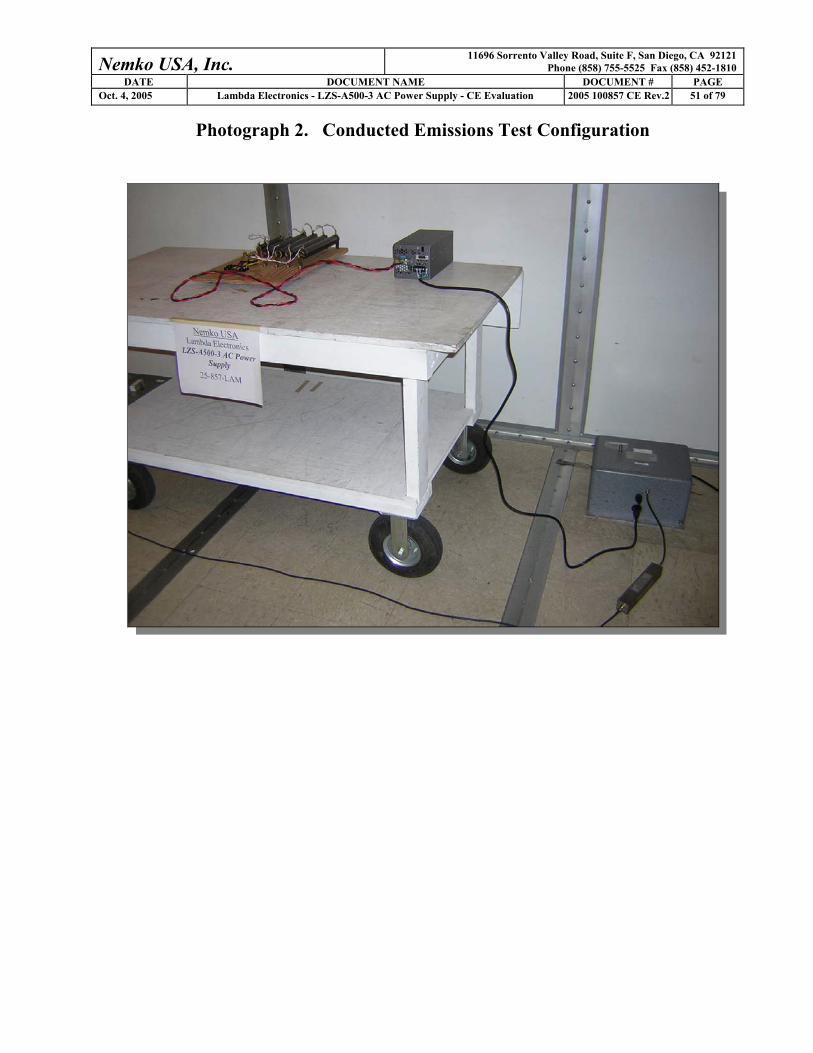
Photograph 2. Conducted Emissions Test Configuration

Nemko USA, Inc. 11696 Sorrento Valley Road, Suite F, San Diego, CA 92121 Phone (858) 755-5525 Fax (858) 452-1810
DATE DOCUMENT NAME DOCUMENT # PAGE Oct. 4, 2005 Lambda Electronics - LZS-A500-3 AC Power Supply - CE Evaluation 2005 100857 CE Rev.2 52 of 79
Photograph 3. Radiated Emissions Test Configuration

Nemko USA, Inc. 11696 Sorrento Valley Road, Suite F, San Diego, CA 92121 Phone (858) 755-5525 Fax (858) 452-1810
DATE DOCUMENT NAME DOCUMENT # PAGE Oct. 4, 2005 Lambda Electronics - LZS-A500-3 AC Power Supply - CE Evaluation 2005 100857 CE Rev.2 53 of 79
Photograph 4. ESD Immunity Test Configuration

Nemko USA, Inc. 11696 Sorrento Valley Road, Suite F, San Diego, CA 92121 Phone (858) 755-5525 Fax (858) 452-1810
DATE DOCUMENT NAME DOCUMENT # PAGE Oct. 4, 2005 Lambda Electronics - LZS-A500-3 AC Power Supply - CE Evaluation 2005 100857 CE Rev.2 54 of 79
Photograph 5. Radio Frequency Immunity Test Configuration

Nemko USA, Inc. 11696 Sorrento Valley Road, Suite F, San Diego, CA 92121 Phone (858) 755-5525 Fax (858) 452-1810
DATE DOCUMENT NAME DOCUMENT # PAGE Oct. 4, 2005 Lambda Electronics - LZS-A500-3 AC Power Supply - CE Evaluation 2005 100857 CE Rev.2 55 of 79
Photograph 6. EFT Immunity Test Configuration

Nemko USA, Inc. 11696 Sorrento Valley Road, Suite F, San Diego, CA 92121 Phone (858) 755-5525 Fax (858) 452-1810
DATE DOCUMENT NAME DOCUMENT # PAGE Oct. 4, 2005 Lambda Electronics - LZS-A500-3 AC Power Supply - CE Evaluation 2005 100857 CE Rev.2 56 of 79
Photograph 7. Power Line Surge Immunity Test Configuration
Nemko USA, Inc. 11696 Sorrento Valley Road, Suite F, San Diego, CA 92121 Phone (858) 755-5525 Fax (858) 452-1810
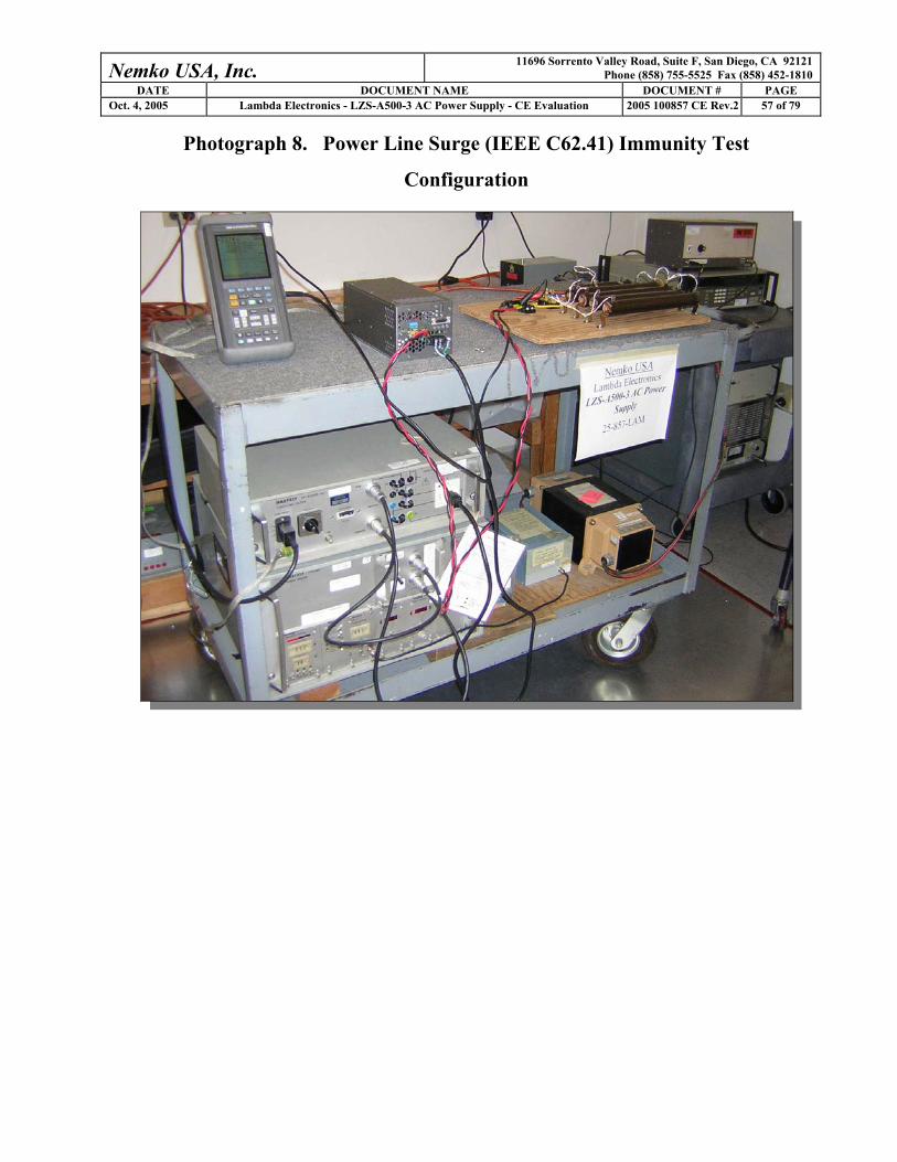
DATE DOCUMENT NAME DOCUMENT # PAGE Oct. 4, 2005 Lambda Electronics - LZS-A500-3 AC Power Supply - CE Evaluation 2005 100857 CE Rev.2 57 of 79
Photograph 8. Power Line Surge (IEEE C62.41) Immunity Test
Configuration
Nemko USA, Inc. 11696 Sorrento Valley Road, Suite F, San Diego, CA 92121 Phone (858) 755-5525 Fax (858) 452-1810
DATE DOCUMENT NAME DOCUMENT # PAGE Oct. 4, 2005 Lambda Electronics - LZS-A500-3 AC Power Supply - CE Evaluation 2005 100857 CE Rev.2 58 of 79
Photograph 9. RF Common Mode Immunity Test Configuration

Nemko USA, Inc. 11696 Sorrento Valley Road, Suite F, San Diego, CA 92121 Phone (858) 755-5525 Fax (858) 452-1810
DATE DOCUMENT NAME DOCUMENT # PAGE Oct. 4, 2005 Lambda Electronics - LZS-A500-3 AC Power Supply - CE Evaluation 2005 100857 CE Rev.2 59 of 79
Photograph 10. I/O RF Common Mode Immunity Test Configuration
Nemko USA, Inc. 11696 Sorrento Valley Road, Suite F, San Diego, CA 92121 Phone (858) 755-5525 Fax (858) 452-1810
DATE DOCUMENT NAME DOCUMENT # PAGE Oct. 4, 2005 Lambda Electronics - LZS-A500-3 AC Power Supply - CE Evaluation 2005 100857 CE Rev.2 60 of 79
Photograph 11. Magnetic Field Immunity Test Configuration

Nemko USA, Inc. 11696 Sorrento Valley Road, Suite F, San Diego, CA 92121 Phone (858) 755-5525 Fax (858) 452-1810
DATE DOCUMENT NAME DOCUMENT # PAGE Oct. 4, 2005 Lambda Electronics - LZS-A500-3 AC Power Supply - CE Evaluation 2005 100857 CE Rev.2 61 of 79
Photograph 12. Voltage Dips and Short Interruptions Immunity Test
Configuration

Nemko USA, Inc. 11696 Sorrento Valley Road, Suite F, San Diego, CA 92121 Phone (858) 755-5525 Fax (858) 452-1810
DATE DOCUMENT NAME DOCUMENT # PAGE Oct. 4, 2005 Lambda Electronics - LZS-A500-3 AC Power Supply - CE Evaluation 2005 100857 CE Rev.2 62 of 79
Photograph 13. Powerline Harmonics and Flicker Test Configuration

Nemko USA, Inc. 11696 Sorrento Valley Road, Suite F, San Diego, CA 92121 Phone (858) 755-5525 Fax (858) 452-1810
DATE DOCUMENT NAME DOCUMENT # PAGE Oct. 4, 2005 Lambda Electronics - LZS-A500-3 AC Power Supply - CE Evaluation 2005 100857 CE Rev.2 1 of 79
APPENDIX A A. Conducted & Radiated Emissions Measurement Uncertainties
1. Introduction
ISO Standard 17025 and ANSI/NCSL Z540-1 (1994) require that all measurements contained in a test report
be “traceable”. “Traceability” is defined in the International Vocabulary of Basic and General Terms in
Metrology (ISO: 1993) as: “the property of the result of a measurement... whereby it can be related to stated
references, usually national or international standards, through an unbroken chain of comparisons, all having
stated uncertainties”.
The purposes of this Appendix are to “state the Measurement Uncertainties” of the conducted emissions and
radiated emissions measurements contained in Section 5 of this Test Report, and to provide a practical
explanation of the meaning of these measurement uncertainties.
2. Statement of the Worst-Case Measurement Uncertainties for the Conducted and
Radiated Emissions Measurements Contained in This Test Report
Table 1: Worst-Case Expanded Uncertainty "U" of Measurement for a k=2 Coverage Factor
Conducted Emissions Measurement Detection Systems Applicable Frequency
Range "U” for a k=2
Coverage Factor
HP8568B Spectrum Analyzer with QPA and HP8447F Preamplifier 150 kHz - 30 MHz +/- 3.0 dB
HP8566B Spectrum Analyzer with QPA and Preselector 9 kHz - 30 MHz +/- 2.9 dB
Radiated Emissions Measurement Detection Systems Applicable Frequency
Range "U” for a k=2
Coverage Factor
HP8568B Spectrum Analyzer with QPA & HP8447F Preamplifier 30 MHz - 200 MHz +4.0 dB, -4.1 dB
HP8568B Spectrum Analyzer with QPA & HP8447F Preamplifier 200 MHz-1000 MHz +/- 3.5 dB
HP8566B Spectrum Analyzer with QPA & Preselector 30 MHz - 200 MHz +3.9 dB, -4.0 dB
HP8566B Spectrum Analyzer with QPA & Preselector 200 MHz-1000 MHz +/- 3.4 dB
HP8566B Spectrum Analyzer with QPA & HP 8449A Preamplifier 1 GHz - 18 GHz +2.5 dB, -2.6 dB
HP8566B Spectrum Analyzer with QPA & HP8449A Preamplifier 18 GHz - 40 GHz +/- 3.4 dB NOTES: 1. Applies to 3 and 10 meter measurement distances 2. Applies to all valid combinations of Transducers (i.e. LISNs, Line Voltage Probes, and Antennas, as appropriate) 3. Excludes the Repeatability of the EUT
Nemko USA, Inc. 11696 Sorrento Valley Road, Suite F, San Diego, CA 92121 Phone (858) 755-5525 Fax (858) 452-1810
DATE DOCUMENT NAME DOCUMENT # PAGE Oct. 4, 2005 Lambda Electronics - LZS-A500-3 AC Power Supply - CE Evaluation 2005 100857 CE Rev.2 2 of 79
3. Practical Explanation of the Meaning of the Conducted and Radiated Emissions Measurement Uncertainties
In the specific case of EMC Measurements in this test report, the measurement uncertainties of the conducted
emissions measurements and the radiated emissions measurements have been calculated in accordance with
the method detailed in the following documents:
o ISO Guide to the Expression of Uncertainty in Measurement (ISO, 1993)
o NIS 81:1994, The Treatment of Uncertainty in EMC Measurements (NAMAS, 1994)
o NIST Technical Note 1297(1994), Guidelines for Evaluating and Expressing the Uncertainty of
NIST Measurement Results (NIST, 1994)
The calculation method used in these documents requires that the stated uncertainty of the measurements be
expressed as an “expanded uncertainty”, U, with a k=2 coverage factor. The practical interpretation of this
method of expressing measurement uncertainty is shown in the following example:
EXAMPLE: Assume that at 39.51 MHz, the (measured) radiated emissions level was equal to +26.5
dBuV/m, and that the +/- 2 standard deviations (i.e. 95% confidence level) measurement uncertainty was
+/- 3.4 dB.
In the example above, the phrase “k = 2 Coverage Factor” simply means that the measurement uncertainty is
stated to cover +/-2 standard deviations (i.e. a 95% confidence interval) about the measurand. The measurand is
the radiated emissions measurement of +26.5 dBuV/m at 39.51 MHz, and the 95% bounds for the uncertainty
are –3.4 dB to + 3.4 dB. One can thus be 95% confident that the “true” value of the radiated emissions
measurement is between +23.1 dBuV/m and +29.5 dBuV/m. In effect, this means that in the above example
there is only a 2.5% chance that the “true” radiated emissions value exceeds +29.5 dBuV/m.
Nemko USA, Inc. 11696 Sorrento Valley Road, Suite F, San Diego, CA 92121 Phone (858) 755-5525 Fax (858) 452-1810
DATE DOCUMENT NAME DOCUMENT # PAGE Oct. 4, 2005 Lambda Electronics - LZS-A500-3 AC Power Supply - CE Evaluation 2005 100857 CE Rev.2 1 of 79
APPENDIX B B. Nemko USA, Inc.’s Test Equipment & Facilities Calibration Program
Nemko USA, Inc. operates a comprehensive Periodic Calibration Program in order to ensure the validity of all
test data. Nemko USA’s Periodic Calibration Program is fully compliant to the requirements of NVLAP
Policy Guide PG-1-1988, ANSI/NCSL Z540-1 (1994), ISO 10012-1 (1993-05-01), ISO Standard 17025, ISO-
9000 and EN 45001. Nemko USA, Inc.’s calibrations program therefore meets or exceed the US national
commercial and military requirements [N.B. ANSI/NCSL Z540-1 (1994) replaces MIL-STD-45662A].
Specifically, all of Nemko USA’s primary reference standard devices (e.g. vector voltmeters, multimeters,
attenuators and terminations, RF power meters and their detector heads, oscilloscope mainframes and plug-
ins, spectrum analyzers, RF preselectors, quasi-peak adapters, interference analyzers, impulse generators,
signal generators and pulse/function generators, field-strength meters and their detector heads, etc.) and
certain secondary standard devices (e.g. RF Preamplifiers used in CISPR 11/22 and FCC Part 15/18 tests) are
periodically recalibrated by:
o A Nemko USA-approved independent (third party) metrology laboratory that uses NIST-
traceable standards and that is ISO Guide 25-accredited as a calibration laboratories by NIST;
or,
o A Nemko USA-approved independent (third party) metrology laboratory that uses NIST-
traceable standards and that is ISO Guide 25-accredited as a calibration laboratory by another
accreditation body (such as A2LA) that is mutually recognized by NIST; or,
o A manufacturer of Measurement and Test Equipment (M&TE), if the manufacturer uses NIST-
traceable standards and is ISO Guide 25-accredited as calibration laboratory either by NIST or
by another accreditation body (such as A2LA) that is mutually recognized by NIST; or
o A manufacturer of M&TE (or by a Nemko USA-approved independent third party metrology
laboratory) that is not ISO Guide 25-accredited. (In these cases, Nemko USA conducts an
annual audit of the manufacturer or metrology laboratory for the purposes of proving traceabilty
to NIST, ensuring that adequate and repeatable calibration procedures are being applied, and
verifying conformity with the other requirements of ISO Guide 25).
In all cases, the entity performing the Calibration is required to furnish Nemko USA with a calibration test
report and/or certificate of calibration, and a “calibration sticker” on each item of M&TE that is successfully
calibrated.
Nemko USA, Inc. 11696 Sorrento Valley Road, Suite F, San Diego, CA 92121 Phone (858) 755-5525 Fax (858) 452-1810
DATE DOCUMENT NAME DOCUMENT # PAGE Oct. 4, 2005 Lambda Electronics - LZS-A500-3 AC Power Supply - CE Evaluation 2005 100857 CE Rev.2 2 of 79
Calibration intervals are normally one year, except when the manufacture advises a shorter interval (e.g. the
HP 8568B Spectrum Analyzer is recalibrated every six months) or if US Government directives or client
requirements demand a shorter interval. Items of instrumentation/related equipment which fail during routine
use, or which suffer visible mechanical damage (during use or while in transit), are sidelined pending repair
and recalibration. (Repairs are carried out either in-house [if minor] or by a Nemko USA-approved
independent [third party] metrology laboratory, or by the manufacturer of the item of M&TE).
Each antenna used for CISPR 11 and CISPR 22 and FCC Part 15 and Part 18 radiated emissions testing (and
for testing to the equivalent European Norms) is calibrated annually by either a NIST (or NVLAP) ISO
Standard 17025-Accredited third-party Antenna Calibration Laboratory or by the antenna’s OEM if the OEM
is NIST or NVLAP ISO Standard 17025-accredited as an antenna calibration laboratory. The antenna
calibrations are performed using the methods specified in Annex G.5 of CISPR 16 (2003) or ANSI C63.4
(2001), including the “Three-Antenna Method”. Certain other kinds of antennas (e.g. magnetic-shielded loop
antennas) are calibrated annually by either a NIST (or NVLAP) ISO Standard 17025-accredited third-party
antenna calibration laboratory, or by the antenna’s OEM if the OEM is NIST or NVLAP ISO Standard 17025-
accredited as an antenna calibration laboratory using the procedures specified in the latest version of SAE
ARP-958.
In accordance with FCC and other regulations, Nemko USA recalibrates its suite of antennas used for radiated
emissions tests on an annual basis. These calibrations are performed as a precursor to the FCC-required
annual revalidation of the Normalized Site Attenuation properties of Nemko USA’s Open Area Test Site.
Nemko USA, Inc. uses the procedures given in both Subclause 16.6 and Annex G.2 of CISPR 16 (2003), and
ANSI C63.4 (2001) when performing the normalized site attenuation measurements.
Nemko USA, Inc. 11696 Sorrento Valley Road, Suite F, San Diego, CA 92121 Phone (858) 755-5525 Fax (858) 452-1810
DATE DOCUMENT NAME DOCUMENT # PAGE Oct. 4, 2005 Lambda Electronics - LZS-A500-3 AC Power Supply - CE Evaluation 2005 100857 CE Rev.2 C1 of 79
APPENDIX C C. NVLAP Accreditation / Nemko Authorization

Nemko USA, Inc. 11696 Sorrento Valley Road, Suite F, San Diego, CA 92121 Phone (858) 755-5525 Fax (858) 452-1810
DATE DOCUMENT NAME DOCUMENT # PAGE Oct. 4, 2005 Lambda Electronics - LZS-A500-3 AC Power Supply - CE Evaluation 2005 100857 CE Rev.2 C2 of 79
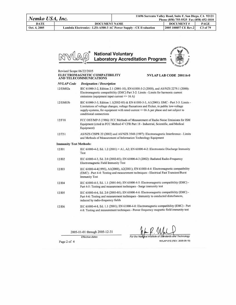
Nemko USA, Inc. 11696 Sorrento Valley Road, Suite F, San Diego, CA 92121 Phone (858) 755-5525 Fax (858) 452-1810
DATE DOCUMENT NAME DOCUMENT # PAGE Oct. 4, 2005 Lambda Electronics - LZS-A500-3 AC Power Supply - CE Evaluation 2005 100857 CE Rev.2 C3 of 79

Nemko USA, Inc. 11696 Sorrento Valley Road, Suite F, San Diego, CA 92121 Phone (858) 755-5525 Fax (858) 452-1810
DATE DOCUMENT NAME DOCUMENT # PAGE Oct. 4, 2005 Lambda Electronics - LZS-A500-3 AC Power Supply - CE Evaluation 2005 100857 CE Rev.2 C4 of 79
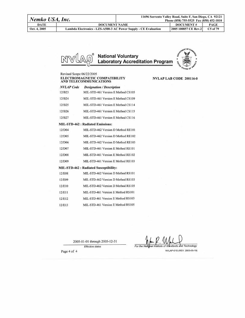
Nemko USA, Inc. 11696 Sorrento Valley Road, Suite F, San Diego, CA 92121 Phone (858) 755-5525 Fax (858) 452-1810
DATE DOCUMENT NAME DOCUMENT # PAGE Oct. 4, 2005 Lambda Electronics - LZS-A500-3 AC Power Supply - CE Evaluation 2005 100857 CE Rev.2 C5 of 79
Nemko USA, Inc. 11696 Sorrento Valley Road, Suite F, San Diego, CA 92121 Phone (858) 755-5525 Fax (858) 452-1810
DATE DOCUMENT NAME DOCUMENT # PAGE Oct. 4, 2005 Lambda Electronics - LZS-A500-3 AC Power Supply - CE Evaluation 2005 100857 CE Rev.2 C6 of 79

Nemko USA, Inc. 11696 Sorrento Valley Road, Suite F, San Diego, CA 92121 Phone (858) 755-5525 Fax (858) 452-1810
DATE DOCUMENT NAME DOCUMENT # PAGE Oct. 4, 2005 Lambda Electronics - LZS-A500-3 AC Power Supply - CE Evaluation 2005 100857 CE Rev.2 C7 of 79

Nemko USA, Inc. 11696 Sorrento Valley Road, Suite F, San Diego, CA 92121 Phone (858) 755-5525 Fax (858) 452-1810
DATE DOCUMENT NAME DOCUMENT # PAGE Oct. 4, 2005 Lambda Electronics - LZS-A500-3 AC Power Supply - CE Evaluation 2005 100857 CE Rev.2 C8 of 79