Heavy Industrial/Marine — J-Line - shopsri.com · ™ heavy industrial/marine — j-line ......
12
54 Heavy Industrial/Marine — J-Line ™ J-Line ™ Interconnection Systems Overview J-Line 4P4W Max. 30 through 200A Tough service in metal for many industrial applications, the J-Line offers a value alternative to MaxGard ® in 3P4W, 30–200 Amp applications with less severe needs. Unique among competitors, the J-Line uses a reversible contract carrier for maximum flexibility in many portable service applications. Design Features Russellstoll ® J-Line Load-Breaking Plugs, Connectors and Receptacles 1. Circuit-interrupting rated safety 2. Cast aluminum, corrosion-resistant copper-free alloy housings and enclosures provide light weight and maximum corrosion resistance, along with electrostatic epoxy powder coat finish 3. Quick conversion between weathertight flap cover and watertight screw cap assemblies. Basic receptacle housing accommodates both covers and is the basic component of all complete units. All watertight configured plugs may be used interchangeably 4. Two grounding arrangements (Style No. 1 and Style No. 2) 5. Four complete J-Lines 30, 60, 100 and 200 amps; 600 VAC/250VDC (plus 150A/270A specials) 6. Flap cover can be rotated and locked in any convenient position 7. Pressure-type solderless wiring terminals 8. Silver-plated contacts 9. One-piece interior assemblies interchangeable from regular to reverse service in the field with a screwdriver 10. Wiring space ample for maximum requirements 11. Cable clamps adjustable for maximum range of cable size. Oil-resistant Neoprene strain-relief bushing compresses around cable tightly, prevents entry of dust and moisture 12. Polarization provides positive non-interchangeability for different electrical systems 13. Reversed contacts flexibility: male–female reversed installation within any housing
Transcript of Heavy Industrial/Marine — J-Line - shopsri.com · ™ heavy industrial/marine — j-line ......
54
www.tnb.com
Heav
y In
dust
rial/M
arin
e —
J-L
ine™
J-Line™ Interconnection Systems Overview
J-Line4P4W Max.
30 through 200A
Tough service in metal for many industrial applications, the J-Line offers a value alternative to MaxGard® in 3P4W, 30–200 Amp applications with less severe needs. Unique among competitors, the J-Line uses a reversible contract carrier for maximum flexibility in many portable service applications.
Design FeaturesRussellstoll® J-Line Load-Breaking Plugs, Connectors and Receptacles
1. Circuit-interrupting rated safety
2. Cast aluminum, corrosion-resistant copper-free alloy housingsand enclosures provide light weight and maximum corrosionresistance, along with electrostatic epoxy powder coat finish
3. Quick conversion between weathertight flap cover and watertightscrew cap assemblies. Basic receptacle housing accommodatesboth covers and is the basic component of all complete units. All watertight configured plugs may be used interchangeably
4. Two grounding arrangements (Style No. 1 and Style No. 2)
5. Four complete J-Lines 30, 60, 100 and 200 amps; 600 VAC/250VDC (plus 150A/270A specials)
6. Flap cover can be rotated and locked in any convenient position
7. Pressure-type solderless wiring terminals
8. Silver-plated contacts
9. One-piece interior assemblies interchangeable from regular to reverse service in the field with a screwdriver
10. Wiring space ample for maximum requirements
11. Cable clamps adjustable for maximum range of cable size. Oil-resistant Neoprene strain-relief bushing compresses around cable tightly, prevents entry of dust and moisture
12. Polarization provides positive non-interchangeability for different electrical systems
13. Reversed contacts flexibility: male–female reversedinstallation within any housing
55
www.tnb.com
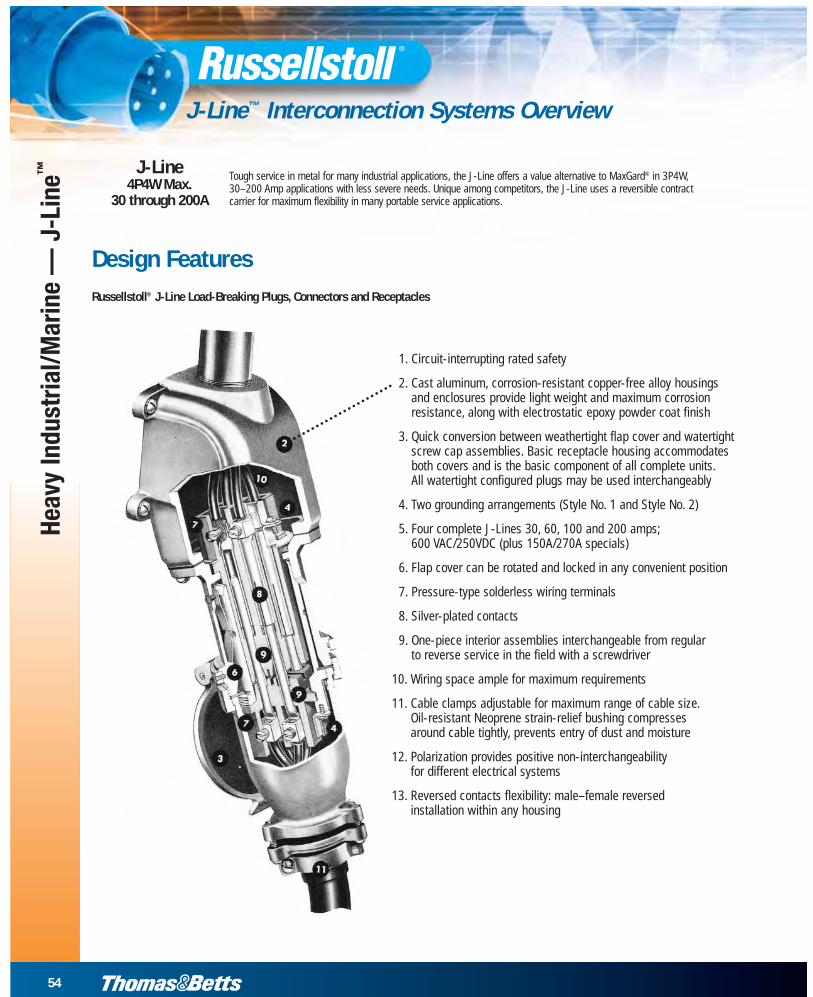
Conversion to Weathertight and Watertight Types
Weathertight J-Linewith flap cover assembly
Watertight J-Linewith screw cap
Substitution of either the flap cover assembly or the screw cap assembly on the housing of the basic receptacle permits quick and easy conversionbetween the weathertight and watertight types. Only a small screwdriveris needed to change in the field.
The basic receptacle housing is constructed with a threaded end to accommodate a screw cap or the collar nut of a watertight plug. A special groove above the threads accommodates the flap cover assembly. The flap cover assembly may be rotated around this grooved shell and the set-screw locked in any convenient position.
The watertight plug, with its collar screwed firmly to the basic receptacle shell,forms a completely watertight connection on either type of receptacle assembly.
These conversion features also permit the use of flap cover or screw cap on connector housings.
Devices offer standard and custom polarizationfor total operator safety so that plugs will fit onlyinto receptacles or connectors having the sameelectrical/specification characteristics.
Visual means of aligning units for a specific,positive polarization are provided:
• Button inside of receptacle housing mates to groove on plug shroud
• Smaller primary guides also assist positive part-part mating
• External I.D. of 1 of 8 polarization indexes visible
• Different polarizations assigned to voltages can’t mate — a safer system!
Polarization
Heavy Industrial/Marine —
J-Line™
J-Line™ Interconnection Systems Overview
56
www.tnb.com
Heav
y In
dust
rial/M
arin
e —
J-L
ine™
J-Line™ Interconnection Systems Overview
30–200/270 Amp (30–200A Load Breaking), Maximum 600VAC/250VDCLoad-Breaking Receptacles, Plugs, Connectors and Inlets
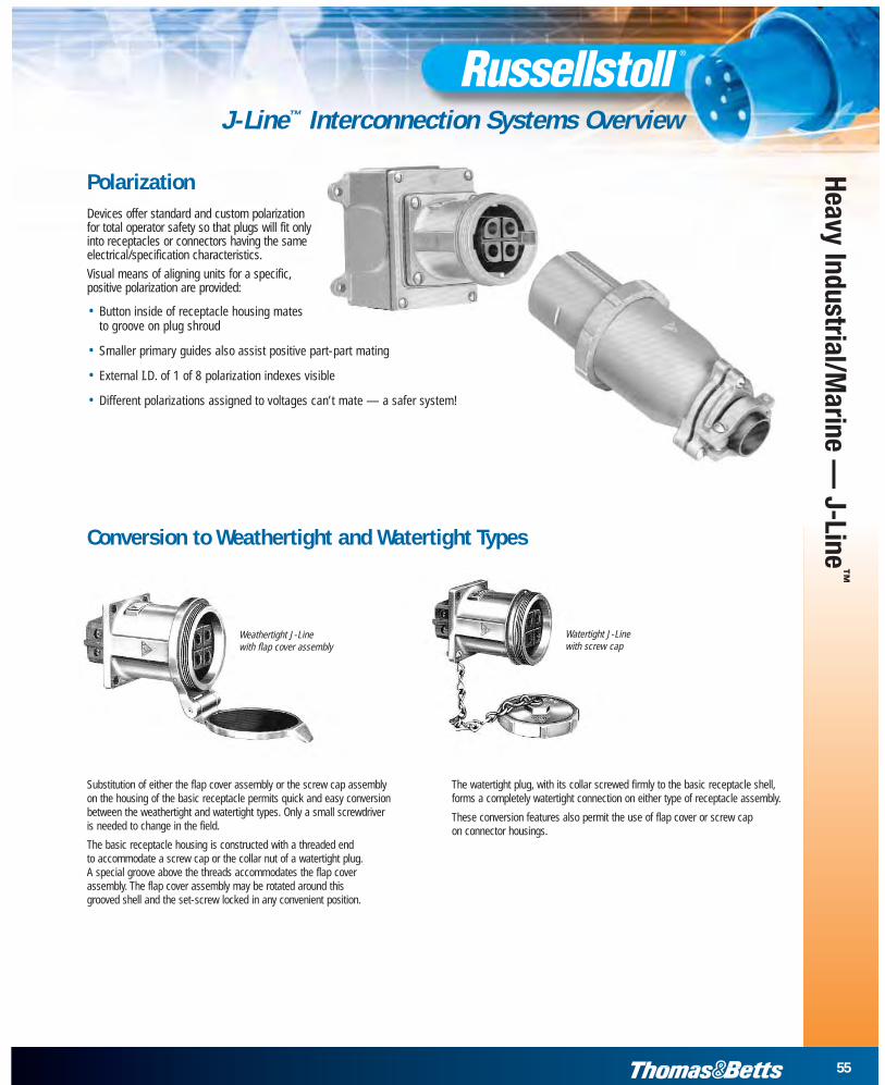
All J-Line plugs, receptacles and connectors can be furnished for ReverseService — male (plug) interiors in the receptacles and female (receptacle)interiors in the plugs. When ordering reverse service, add a final suffix “R” to the complete catalog number. Price on application.
Example: JRFA334HR
J-Line receptacle and plug interior assemblies of the same amperage may be quickly interchanged from regular to reverse service (or vice versa) in the field. A screwdriver is the only tool required.
Example: Panel-mounted low-profile receptacles with male interiors act as male inlets in remote equipment; receive power from FemalePlugs. (Cup cap also recommended.)
Reverse ServiceNote the complete interior assemblies have now beeninterchanged so that the male (plug) interior assembly is positioned in the receptacle housing and the female(receptacle) interior assembly is positioned in the plug housing.
Regular ServiceInterior assemblies placed in normal, standard positions —female interior assembly is positioned in the receptaclehousing and the male interior assembly is positioned in the plug housing.
Reversed Contacts ServiceFor all Weathertight and Watertight types
57
www.tnb.com
Heavy Industrial/Marine —
J-Line™
J-Line™ Interconnection Systems Overview
30–200/270 Amp (30–200A Load-Breaking), Maximum 600VAC/250VDCLoad-Breaking Receptacles, Plugs, Connectors and Inlets
Grounding Data
Portable cord3 conductors + G
Grounding thruplug & receptaclehousing
Groundingthru conduitsystem onlyEquipment ground
connected toplug shell
PlugReceptacle
Portable cord4 conductors
Grounding thruplug & receptaclehousing
Equipment groundconnected to extrapole and plug shell
Plug Receptacle
Factory installedjumper
4th groundingwire – if desired
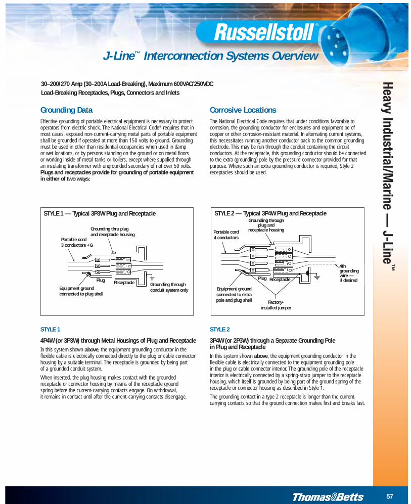
STYLE 1 — Typical 3P3W Plug and Receptacle STYLE 2 — Typical 3P4W Plug and Receptacle
STYLE 1
4P4W (or 3P3W) through Metal Housings of Plug and ReceptacleIn this system shown above, the equipment grounding conductor in theflexible cable is electrically connected directly to the plug or cable connectorhousing by a suitable terminal. The receptacle is grounded by being part of a grounded conduit system.
When inserted, the plug housing makes contact with the groundedreceptacle or connector housing by means of the receptacle ground spring before the current-carrying contacts engage. On withdrawal, it remains in contact until after the current-carrying contacts disengage.
STYLE 2
3P4W (or 2P3W) through a Separate Grounding Pole in Plug and ReceptacleIn this system shown above, the equipment grounding conductor in theflexible cable is elec trically connected to the equipment grounding pole in the plug or cable connector interior. The grounding pole of the receptacleinterior is elec trically connected by a spring-strap jumper to the receptaclehousing, which itself is grounded by being part of the ground spring of thereceptacle or con nector housing as described in Style 1.
The grounding contact in a type 2 receptacle is longer than the current-carrying contacts so that the ground connection makes first and breaks last.
Effective grounding of portable electrical equipment is necessary to protectoperators from electric shock. The National Electrical Code® requires that inmost cases, exposed non-current-carrying metal parts of portable equipmentshall be grounded if operated at more than 150 volts to ground. Groundingmust be used in other than residential occupancies when used in damp or wet locations, or by persons standing on the ground or on metal floors or working inside of metal tanks or boilers, except where supplied throughan insulating transformer with ungrounded secondary of not over 50 volts. Plugs and receptacles provide for grounding of portable equipmentin either of two ways:
Portable cord3 conductors +G
Grounding thru plugand receptacle housing
Receptacle
Factory- installed jumper
Equipment groundconnected to extrapole and plug shell
Portable cord4 conductors
Grounding throughplug and
receptacle housing
4thgroundingwire — if desiredPlug Plug
Equipment groundconnected to plug shell
Grounding throughconduit system only
Receptacle
The National Electrical Code requires that under conditions favorable tocorrosion, the grounding conductor for enclosures and equipment be ofcopper or other corrosion-resistant material. In alternating current systems,this necessitates running another conductor back to the common groundingelectrode. This may be run through the conduit containing the circuitconductors. At the receptacle, this grounding conductor should be connectedto the extra (grounding) pole by the pressure connector provided for thatpurpose. Where such an extra grounding conductor is required, Style 2receptacles should be used.
Corrosive Locations
58
www.tnb.com
Heav
y In
dust
rial/M
arin
e —
J-L
ine™
J-Line™ Plugs, Connectors and Receptacles
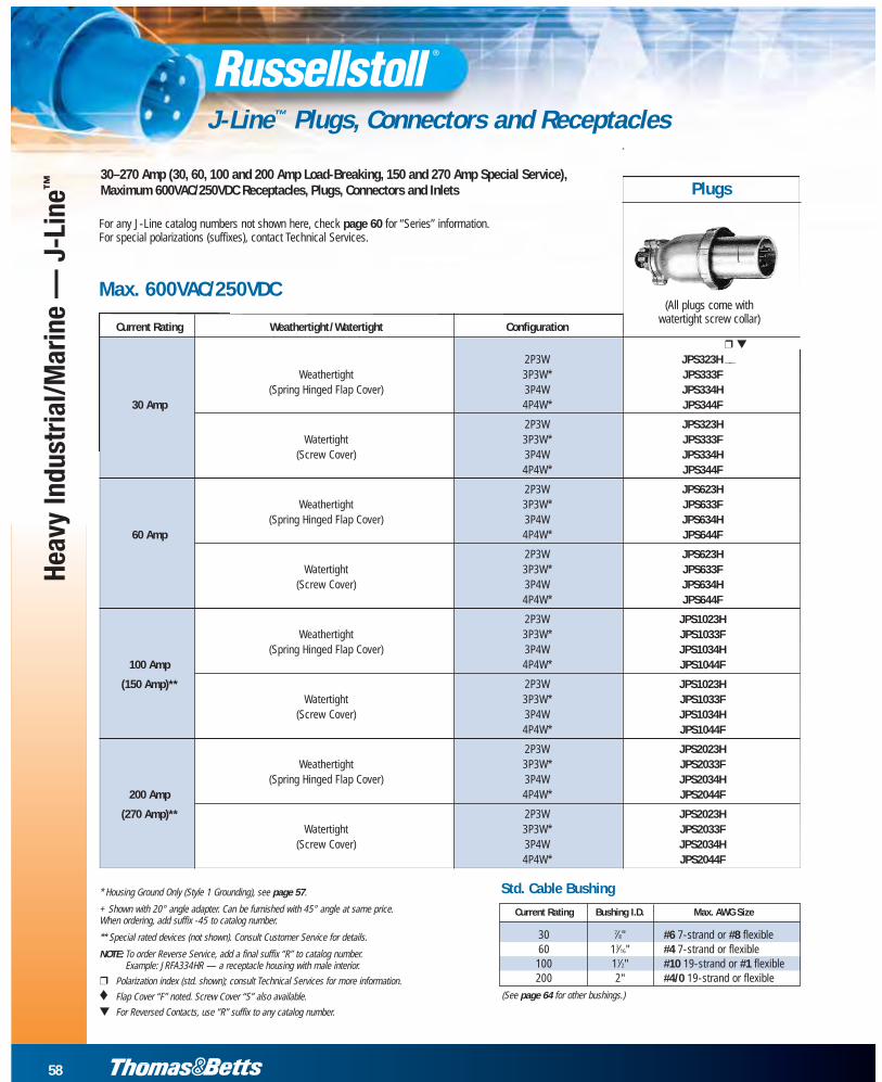
30–270 Amp (30, 60, 100 and 200 Amp Load-Breaking, 150 and 270 Amp Special Service),Maximum 600VAC/250VDC Receptacles, Plugs, Connectors and Inlets Plugs
Current Rating Weathertight/Watertight Configuration
❒ ▼
2P3W JPS323H __Weathertight 3P3W* JPS333F
(Spring Hinged Flap Cover) 3P4W JPS334H30 Amp 4P4W* JPS344F
2P3W JPS323HWatertight 3P3W* JPS333F
(Screw Cover) 3P4W JPS334H4P4W* JPS344F
2P3W JPS623HWeathertight 3P3W* JPS633F
(Spring Hinged Flap Cover) 3P4W JPS634H60 Amp 4P4W* JPS644F
2P3W JPS623HWatertight 3P3W* JPS633F
(Screw Cover) 3P4W JPS634H4P4W* JPS644F
2P3W JPS1023HWeathertight 3P3W* JPS1033F
(Spring Hinged Flap Cover) 3P4W JPS1034H100 Amp 4P4W* JPS1044F
(150 Amp)** 2P3W JPS1023HWatertight 3P3W* JPS1033F
(Screw Cover) 3P4W JPS1034H4P4W* JPS1044F
2P3W JPS2023HWeathertight 3P3W* JPS2033F
(Spring Hinged Flap Cover) 3P4W JPS2034H200 Amp 4P4W* JPS2044F
(270 Amp)** 2P3W JPS2023HWatertight 3P3W* JPS2033F
(Screw Cover) 3P4W JPS2034H4P4W* JPS2044F
For any J-Line catalog numbers not shown here, check page 60 for “Series” information.For special polarizations (suffixes), contact Technical Services.
(All plugs come with watertight screw collar)
Max. 600VAC/250VDC
* Housing Ground Only (Style 1 Grounding), see page 57.
+ Shown with 20° angle adapter. Can be furnished with 45° angle at same price. When ordering, add suffix -45 to catalog number.
** Special rated devices (not shown). Consult Customer Service for details.
NOTE: To order Reverse Service, add a final suffix “R” to catalog number. Example: JRFA334HR — a receptacle housing with male interior.
❒ Polarization index (std. shown); consult Technical Services for more information.
♦ Flap Cover “F” noted. Screw Cover “S” also available.
▼ For Reversed Contacts, use “R” suffix to any catalog number.
Std. Cable Bushing
Current Rating Bushing I.D. Max. AWG Size
30 7⁄8" #6 7-strand or #8 flexible60 13⁄16" #4 7-strand or flexible
100 11⁄2" #10 19-strand or #1 flexible200 2" #4/0 19-strand or flexible
(See page 64 for other bushings.)
59
www.tnb.com
Heavy Industrial/Marine —
J-Line™
J-Line™ Plugs, Connectors and Receptacles
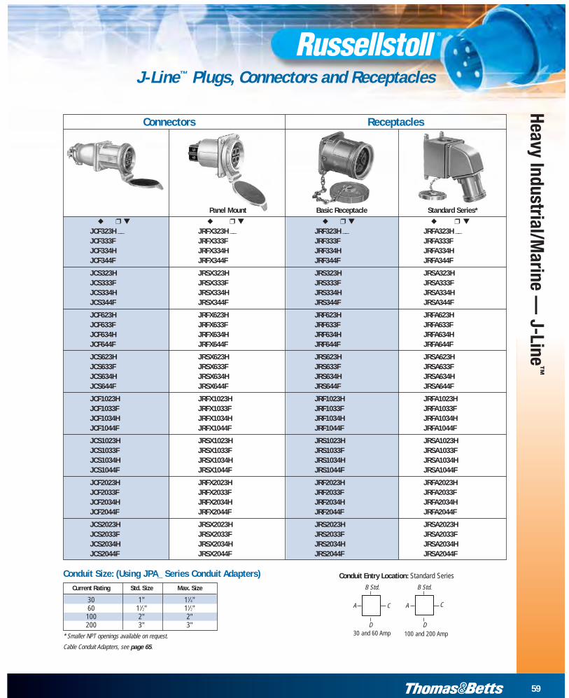
Connectors Receptacles
Conduit Entry Location: Standard Series
30 and 60 Amp 100 and 200 Amp
B Std.
A C
D
B Std.
A C
D
Panel Mount Basic Receptacle Standard Series*
◆ ❒ ▼ ◆ ❒ ▼ ◆ ❒ ▼ ◆ ❒ ▼
JCF323H __ JRFX323H __ JRF323H __ JRFA323H __JCF333F JRFX333F JRF333F JRFA333FJCF334H JRFX334H JRF334H JRFA334HJCF344F JRFX344F JRF344F JRFA344F
JCS323H JRSX323H JRS323H JRSA323HJCS333F JRSX333F JRS333F JRSA333FJCS334H JRSX334H JRS334H JRSA334HJCS344F JRSX344F JRS344F JRSA344F
JCF623H JRFX623H JRF623H JRFA623HJCF633F JRFX633F JRF633F JRFA633FJCF634H JRFX634H JRF634H JRFA634HJCF644F JRFX644F JRF644F JRFA644F
JCS623H JRSX623H JRS623H JRSA623HJCS633F JRSX633F JRS633F JRSA633FJCS634H JRSX634H JRS634H JRSA634HJCS644F JRSX644F JRS644F JRSA644F
JCF1023H JRFX1023H JRF1023H JRFA1023HJCF1033F JRFX1033F JRF1033F JRFA1033FJCF1034H JRFX1034H JRF1034H JRFA1034HJCF1044F JRFX1044F JRF1044F JRFA1044F
JCS1023H JRSX1023H JRS1023H JRSA1023HJCS1033F JRSX1033F JRS1033F JRSA1033FJCS1034H JRSX1034H JRS1034H JRSA1034HJCS1044F JRSX1044F JRS1044F JRSA1044F
JCF2023H JRFX2023H JRF2023H JRFA2023HJCF2033F JRFX2033F JRF2033F JRFA2033FJCF2034H JRFX2034H JRF2034H JRFA2034HJCF2044F JRFX2044F JRF2044F JRFA2044F
JCS2023H JRSX2023H JRS2023H JRSA2023HJCS2033F JRSX2033F JRS2033F JRSA2033FJCS2034H JRSX2034H JRS2034H JRSA2034HJCS2044F JRSX2044F JRS2044F JRSA2044F
Current Rating Std. Size Max. Size
30 1" 11⁄4"60 11⁄2" 11⁄2"
100 2" 2"200 3" 3"
* Smaller NPT openings available on request.
Cable Conduit Adapters, see page 65.
Conduit Size: (Using JPA_ Series Conduit Adapters)
60
www.tnb.com
Heav
y In
dust
rial/M
arin
e —
J-L
ine™
J-Line™ Construction
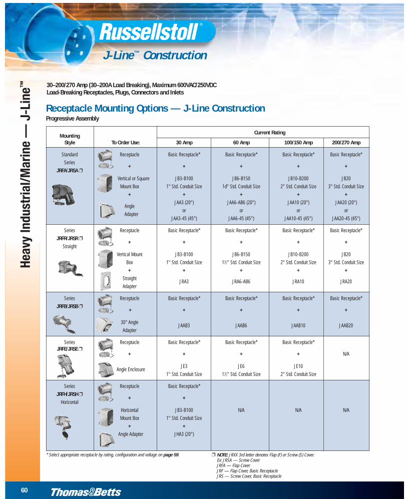
30–200/270 Amp (30–200A Load Breaking), Maximum 600VAC/250VDCLoad-Breaking Receptacles, Plugs, Connectors and Inlets
MountingCurrent Rating
Style To Order Use: 30 Amp 60 Amp 100/150 Amp 200/270 Amp
Standard Receptacle Basic Receptacle* Basic Receptacle* Basic Receptacle* Basic Receptacle*
Series+ + + + +
JRFA/JRSA ❒
Vertical or Square JB3-B100 JB6-B150 JB10-B200 JB20
Mount Box 1" Std. Conduit Size 1d" Std. Conduit Size 2" Std. Conduit Size 3" Std. Conduit Size
+ + + + +
AngleJAA3 (20°) JAA6-AB6 (20°) JAA10 (20°) JAA20 (20°)
Adapteror or or or
JAA3-45 (45°) JAA6-45 (45°) JAA10-45 (45°) JAA20-45 (45°)
Series Receptacle Basic Receptacle* Basic Receptacle* Basic Receptacle* Basic Receptacle*
JRFR/JRSR ❒+ + + + +
Straight
Vertical Mount JB3-B100 JB6-B150 JB10-B200 JB20
Box 1" Std. Conduit Size 11⁄2" Std. Conduit Size 2" Std. Conduit Size 3" Std. Conduit Size
+ + + + +
StraightJRA3 JRA6-AB6 JRA10 JRA20
Adapter
Series Receptacle Basic Receptacle* Basic Receptacle* Basic Receptacle* Basic Receptacle*
JRFB/JRSB ❒+ + + + +
30° AngleJAAB3 JAAB6 JAAB10 JAAB20
Adapter
Series Receptacle Basic Receptacle* Basic Receptacle* Basic Receptacle*JRFE/JRSE ❒
+ + + + N/A
Angle EnclosureJE3 JE6 JE10
1" Std. Conduit Size 11⁄2" Std. Conduit Size 2" Std. Conduit Size
Series Receptacle Basic Receptacle*
JRFH/JRSH ❒+ +
Horizontal
Horizontal JB3-B100 N/A N/A N/A
Mount Box 1" Std. Conduit Size
+ +
Angle Adapter JHA3 (20°)
* Select appropriate receptacle by rating, configuration and voltage on page 59. ❒ NOTE: JRXX 3rd letter denotes Flap (F) or Screw (S) Cover.Ex: JRSA — Screw CoverJRFA — Flap CoverJRF — Flap Cover, Basic ReceptacleJRS — Screw Cover, Basic Receptacle
Receptacle Mounting Options — J-Line ConstructionProgressive Assembly
61
www.tnb.com
Heavy Industrial/Marine —
J-Line™
J-Line™ Dimensions
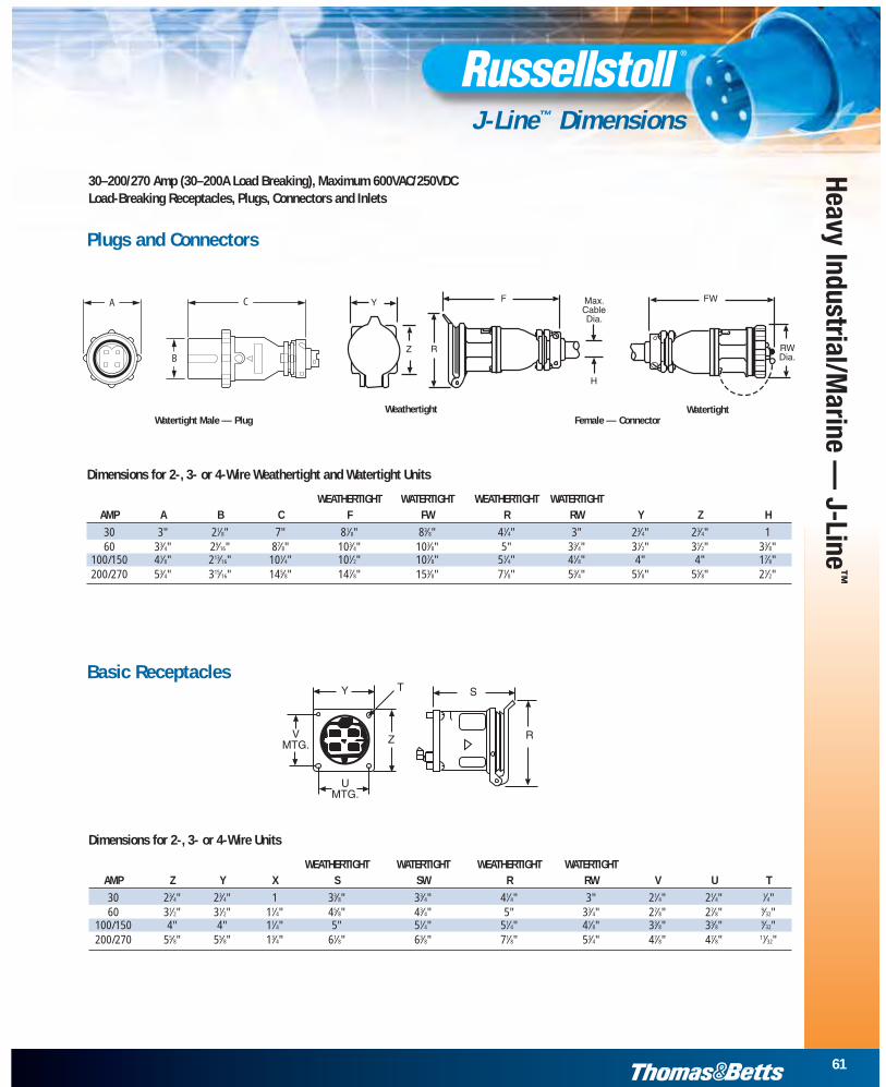
30–200/270 Amp (30–200A Load Breaking), Maximum 600VAC/250VDCLoad-Breaking Receptacles, Plugs, Connectors and Inlets
Dimensions for 2-, 3- or 4-Wire Units
WEATHERTIGHT WATERTIGHT WEATHERTIGHT WATERTIGHTAMP Z Y X S SW R RW V U T
30 23⁄4" 23⁄4" 1 33⁄8" 33⁄4" 41⁄4" 3" 21⁄4" 21⁄4" 1⁄4"60 31⁄2" 31⁄2" 11⁄4" 45⁄8" 43⁄4" 5" 33⁄4" 27⁄8" 27⁄8" 9⁄32"
100/150 4" 4" 11⁄4" 5" 51⁄4" 51⁄4" 41⁄8" 33⁄8" 33⁄8" 9⁄32"200/270 55⁄8" 55⁄8" 13⁄4" 61⁄8" 63⁄8" 71⁄8" 53⁄4" 47⁄8" 47⁄8" 11⁄32"
Plugs and Connectors
Dimensions for 2-, 3- or 4-Wire Weathertight and Watertight Units
WEATHERTIGHT WATERTIGHT WEATHERTIGHT WATERTIGHTAMP A B C F FW R RW Y Z H
30 3" 21⁄8" 7" 81⁄8" 83⁄8" 41⁄4" 3" 23⁄4" 23⁄4" 160 33⁄4" 29⁄16" 87⁄8" 103⁄4" 103⁄8" 5" 33⁄4" 31⁄2" 31⁄2" 33⁄8"
100/150 41⁄8" 213⁄16" 101⁄4" 101⁄2" 107⁄8" 51⁄4" 41⁄8" 4" 4" 17⁄8"200/270 53⁄4" 315⁄16" 145⁄8" 147⁄8" 153⁄8" 71⁄8" 53⁄4" 55⁄8" 55⁄8" 21⁄2"
WeathertightFemale — Connector
WatertightWatertight Male — Plug
Basic Receptacles
A C
B
Heav
y In
dust
rial/M
arin
e —
J-L
ine™
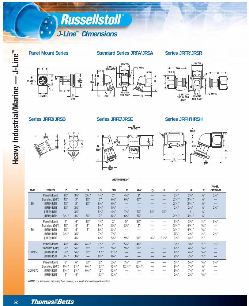
J-Line™ Dimensions
Panel Mount Series Standard Series JRFA/JRSA Series JRFR/JRSR
Series JRFB/JRSB Series JRFE/JRSE Series JRFH/HRSH
NOTE: U = horizontal mounting hole centers; V = vertical mounting hole centers.
WEATHERTIGHT
PANELAMP SERIES Z Y X S SW R RW Q P V U T OPENING
Panel Mount 31⁄2" 31⁄2" 29⁄16" 13⁄4" 2" 41⁄4" 3" — — 27⁄8" 27⁄8" 1⁄4" 23⁄4"Standard (20°) 41⁄2" 3" 21⁄8" 7" 61⁄2" 63⁄4" 63⁄4" — — 211⁄16" 311⁄16" 1⁄4" —
30 JRFR/JRSR 41⁄2" 3" 21⁄8" 61⁄8" 61⁄2" — — — — 211⁄16" 311⁄16" 1⁄4" —JRFB/JRSB 31⁄8" 31⁄8" — 53⁄4" 53⁄4" — — — — 21⁄4" 21⁄4" 1⁄4" 21⁄4"JRFE/JRSE — 31⁄2" — 51⁄4" 45⁄8" 71⁄8" 71⁄8" 11⁄4" 23⁄8" — 4 1⁄4" —JRFH/JRSH 35⁄16" 41⁄2" 21⁄8" 7" 61⁄2" 65⁄8" 65⁄8" — — 211⁄16" 311⁄16" 1⁄4" —
Panel Mount 4" 4" 37⁄8" 13⁄4" 2" 5" 33⁄4" — — 33⁄8" 33⁄8" 9⁄32" 31⁄4"Standard (20°) 55⁄8" 4" 3" 91⁄4" 85⁄8" 87⁄8" 9" — — 313⁄16" 413⁄16" 11⁄32" —
60 JRFR/JRSR 55⁄8" 4" 3" 83⁄8" 81⁄2" — — — — 313⁄16" 415⁄16" 11⁄32" —JRFB/JRSB 33⁄16" 35⁄8" — 73⁄8" 73⁄8" — — — — 23⁄16" 25⁄8" 9⁄32" 21⁄2"JRFE/JRSE — 41⁄4" — 63⁄8" 53⁄4" 93⁄4" 91⁄2" 19⁄16" 311⁄16" 31⁄8" 41⁄2" 9⁄32" —
Panel Mount 41⁄4" 41⁄4" 47⁄16" 13⁄4" 2" 51⁄4" 41⁄8" — — 35⁄8" 35⁄8" 9⁄32" 31⁄2"Standard (20°) 51⁄2" 51⁄2" 31⁄2" 101⁄2" 97⁄8" 97⁄8" 93⁄4" — — 63⁄4" 41⁄4" 11⁄32" —
100/150 JRFR/JRSR 51⁄2" 51⁄2" 31⁄2" 111⁄4" 117⁄8" — — — — 63⁄4" 41⁄4" 11⁄32" —JRFB/JRSB 33⁄16" 35⁄8" — 81⁄4" 81⁄4" — — — — 23⁄16" 25⁄8" 9⁄32" —
Panel Mount 6" 6" 57⁄8" 2" 21⁄2" 71⁄8" 53⁄4" — — 51⁄4" 51⁄4" 11⁄32" 51⁄8"Standard (20°) 85⁄16" 85⁄16" 65⁄16" 157⁄8" 155⁄8" 1211⁄16" 125⁄16" — — 95⁄8" 71⁄8" 3⁄8" —
200/270 JRFR/JRSR 85⁄16" 85⁄16" 65⁄16" 15" 151⁄2" — — — — 95⁄8" 71⁄8" 3⁄8" —JRFB/JRSB 4" 4" — 121⁄4" 121⁄4" — — — — 23⁄4" 23⁄4" 11⁄32" —
62
www.tnb.com
63
www.tnb.com
Heavy Industrial/Marine —
J-Line™
J-Line™ Accessories
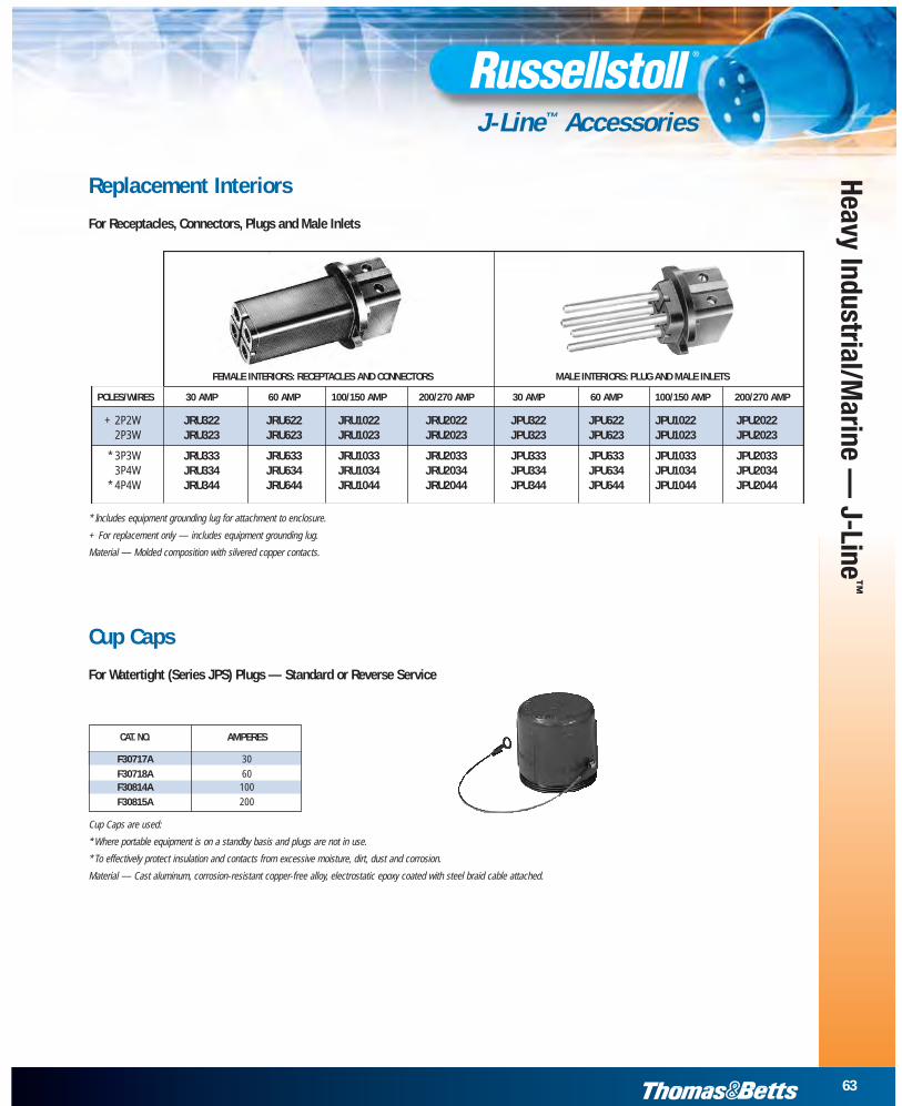
CAT. NO. AMPERES
F30717A 30
F30718A 60F30814A 100
F30815A 200
Replacement Interiors
For Receptacles, Connectors, Plugs and Male Inlets
FEMALE INTERIORS: RECEPTACLES AND CONNECTORS MALE INTERIORS: PLUG AND MALE INLETS
POLES/WIRES 30 AMP 60 AMP 100/150 AMP 200/270 AMP 30 AMP 60 AMP 100/150 AMP 200/270 AMP
+ 2P2W JRU322 JRU622 JRU1022 JRU2022 JPU322 JPU622 JPU1022 JPU20222P3W JRU323 JRU623 JRU1023 JRU2023 JPU323 JPU623 JPU1023 JPU2023
* 3P3W JRU333 JRU633 JRU1033 JRU2033 JPU333 JPU633 JPU1033 JPU20333P4W JRU334 JRU634 JRU1034 JRU2034 JPU334 JPU634 JPU1034 JPU2034
* 4P4W JRU344 JRU644 JRU1044 JRU2044 JPU344 JPU644 JPU1044 JPU2044
* Includes equipment grounding lug for attachment to enclosure.
+ For replacement only — includes equipment grounding lug.
Material — Molded composition with silvered copper contacts.
Cup Caps
For Watertight (Series JPS) Plugs — Standard or Reverse Service
Cup Caps are used:
* Where portable equipment is on a standby basis and plugs are not in use.
* To effectively protect insulation and contacts from excessive moisture, dirt, dust and corrosion.
Material — Cast aluminum, corrosion-resistant copper-free alloy, electrostatic epoxy coated with steel braid cable attached.

64
www.tnb.com
Heav
y In
dust
rial/M
arin
e —
J-L
ine™
J-Line™ Accessories
Cable Bushings
For J-Line Plugs and ConnectorsBoxed catalog numbers are standard bushing sizes. To order non-standard bushing, specify as follows: example JPS634H/JG65.
HOLE DIAMETERFOR CABLE 30 AMP 60 AMP 100/150 AMP 200/270 AMP
.375" JG31
.500" JG32
.563" JG325
.594" JG32B
.625" JG33 JG63
.750" JG34 JG64 JG104
.781" JG341
.875" JG35 JG65 JG105
.938" JG3551.000" JG36* JG66 JG106 JG2061.125" JG361*1.188" JG67 JG107 JG2071.313" JG108 JG2081.375" JG69*1.500" JG610* JG1010 JG20101.688" JG1011 JG20111.813" JG20121.875" JG1013*2.000" JG20142.125" JG20152.500" JG2016*
NOTE:Boxed numbers denote standard bushing size supplied.
When ordering, select bushing size slightly larger than your cable O.D. for best fit.
Material — Neoprene.
Identification letter inside hole.
Standard Cable Bushings
Oversize Cable Bushings
Size No. 3, 6, 10 and 20 Size No. 3, 6, 10 and 20
65
www.tnb.com
Heavy Industrial/Marine —
J-Line™
J-Line™ Accessories
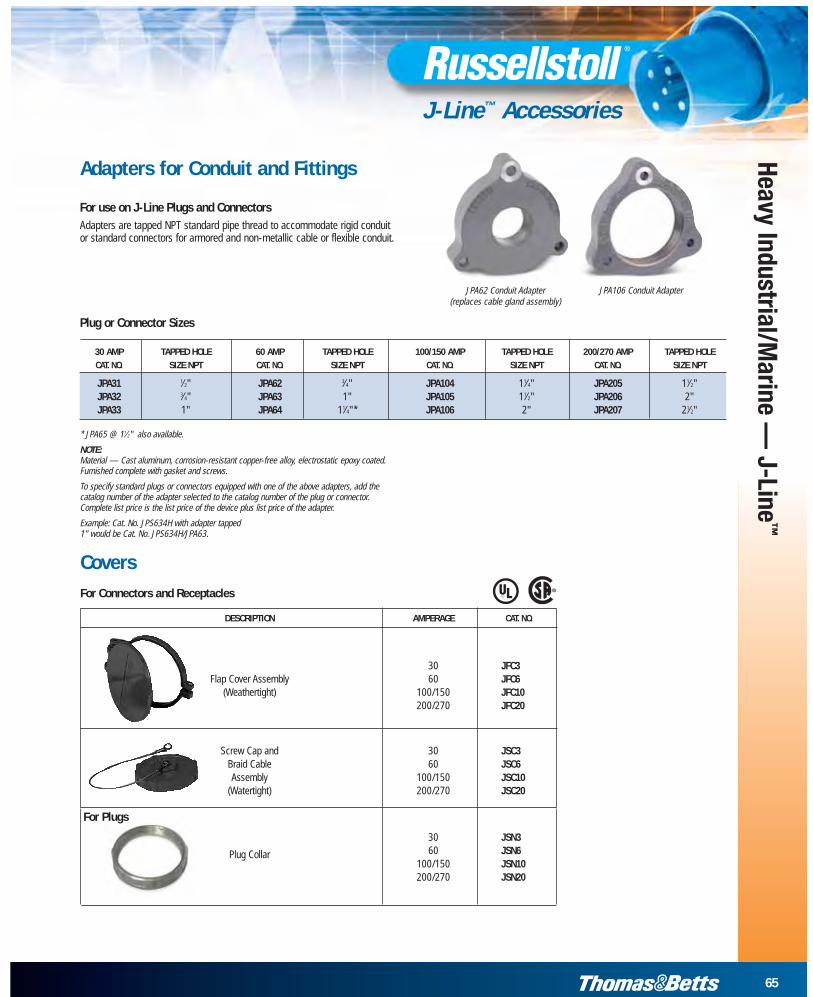
Adapters for Conduit and Fittings
For use on J-Line Plugs and ConnectorsAdapters are tapped NPT standard pipe thread to accommodate rigid conduit or standard connectors for armored and non-metallic cable or flexible conduit.
* JPA65 @ 11⁄2" also available.
NOTE:Material — Cast aluminum, corrosion-resistant copper-free alloy, electrostatic epoxy coated.Furnished complete with gasket and screws.
To specify standard plugs or connectors equipped with one of the above adapters, add thecatalog number of the adapter selected to the catalog number of the plug or connector.Complete list price is the list price of the device plus list price of the adapter.
Example: Cat. No. JPS634H with adapter tapped 1" would be Cat. No. JPS634H/JPA63.
JPA62 Conduit Adapter(replaces cable gland assembly)
CoversFor Connectors and Receptacles ®
Plug or Connector Sizes
30 AMP TAPPED HOLE 60 AMP TAPPED HOLE 100/150 AMP TAPPED HOLE 200/270 AMP TAPPED HOLECAT. NO. SIZE NPT CAT. NO. SIZE NPT CAT. NO. SIZE NPT CAT. NO. SIZE NPT
JPA31 1⁄2" JPA62 3⁄4" JPA104 11⁄4" JPA205 11⁄2"JPA32 3⁄4" JPA63 1" JPA105 11⁄2" JPA206 2"JPA33 1" JPA64 11⁄4"* JPA106 2" JPA207 21⁄2"
JPA106 Conduit Adapter
DESCRIPTION AMPERAGE CAT. NO.
30 JFC3Flap Cover Assembly 60 JFC6
(Weathertight) 100/150 JFC10200/270 JFC20
Screw Cap and 30 JSC3Braid Cable 60 JSC6Assembly 100/150 JSC10
(Watertight) 200/270 JSC20
For Plugs
30 JSN3
Plug Collar 60 JSN6100/150 JSN10200/270 JSN20