Heavy Duty Bench Top Presses - PW ROMEX duty STEEL keyed & bolted ... 3848 3778 5160 5034 5733 5593...
12
Features: • • • • • • • • • Heavy duty STEEL keyed & bolted construction. Adjustable work heights – Choose from three different built-in height settings (2” increments). Open work area – Allows for through feed or side feed of large parts. Removable, oversized ground tool plate, dowel pinned to press frame – Provides precision location of tool plate to press frame. Press designed to accept 5” Bore NFPA standard cylinders, Multi-Stage cylinders, or optional Triple Rod Cylinders. Optional External Mounted Non-Rotating Feature. Strokes from 1” to 6”. Easy to Assemble or can be ordered fully assembled. Finish – All steel parts are Black Oxide Plated, aluminum parts are Anodized. Heavy Duty Bench Top Presses Heavy Duty Bench Top Press shown with 5” Bore (3) Stage Multi-Stage Cylinder and Micro-Adjust precision stroke adjustment. Heavy Duty Bench Top Press shown with 5” Bore Single-Stage Triple Rod Cylinder and Tooling Plate. Model: BTP-502 Model: BTP-501 (FOR SINGLE PISTON ROD, 5” BORE, MF1 MOUNT CYLINDERS) (FOR ‘TRA’ TRIPLE PISTON ROD, 5” BORE, MF1 MOUNT CYLINDERS)
-
Upload
truongcong -
Category
Documents
-
view
216 -
download
2
Transcript of Heavy Duty Bench Top Presses - PW ROMEX duty STEEL keyed & bolted ... 3848 3778 5160 5034 5733 5593...

Features:•
•
•
•
•
•
•
•
•
Heavy duty STEEL keyed & bolted
construction.
Adjustable work heights – Choose from three
different built-in height settings (2” increments).
Open work area – Allows for through feed or
side feed of large parts.
Removable, oversized ground tool plate, dowel
pinned to press frame – Provides precision
location of tool plate to press frame.
Press designed to accept 5” Bore NFPA
standard cylinders, Multi-Stage cylinders,
or optional Triple Rod Cylinders.
Optional External Mounted Non-Rotating
Feature.
Strokes from 1” to 6”.
Easy to Assemble or can be ordered fully
assembled.
Finish – All steel parts are Black Oxide
Plated, aluminum parts are Anodized.
Heavy Duty Bench Top Presses
Heavy Duty Bench Top Press shown with 5”Bore (3) Stage Multi-Stage Cylinder andMicro-Adjust precision stroke adjustment.
Heavy Duty Bench Top Press shown with 5”Bore Single-Stage Triple Rod Cylinder andTooling Plate.
Model:BTP-502
Model:BTP-501(FOR SINGLE PISTONROD, 5” BORE,MF1 MOUNTCYLINDERS)
(FOR ‘TRA’ TRIPLEPISTON ROD, 5” BORE,MF1 MOUNTCYLINDERS)

TO ORDER, SPECIFY:Series, Model and Options
BTP 501 -- a
Series Model Options
BTP Bench Top PressFrame
501 5” Bore Cylinder Mounting(Single Stage or Multi-Stage)
502 5” Bore Triple Rod CylinderMounting
ANRE
U
Fully Assembled (Press & Cyl.)
Non-Rotating External
Un-Assembled Unit
(Specify Cyl. Stroke & Rod Dia.)
(Order Cylinder Separately)
NOTES:
2.)
3.)
MOUNTING BRACKETS ARE REVERSEABLE AND CAN BE ASSEMBLED ON INSIDE OF PRESS FRAME TO REDUCE OVERALL WIDTH.
WEIGHT: 120 POUNDS (PRESS FRAME ONLY).
DIMENSION REFLECTS THE PRESS TOP PLATE MOUNTED IN THE BOTTOM (LOWEST) POSITION.ADD 2.” FOR MID POSITION AND 4.” FOR TOP POSITION.
�
BENCH TOP PRESS: HOW TO ORDER
2
8.5
PRESS FRAME WIDTH
(ASSEMBLED)
.75
MIDDLE
TOP
BOTTOM
12.0
13/16Ø MTG. HOLES
13.62
15.0
(4) 3/8-24 X .5 DEEP TAPPED HOLES
(2) X .5 DEEP REAMED HOLES.3755
.3760
3.50
1.751.00
2.00
3.75 3.75
TOOL PLATE DETAIL
(BOTTOM SIDE)
10.0
8.5
(2) 1Ø TIE BARS
2.0
18.0
11.5
2.752.755.12
15.38 (TOP)
13.38 (MID)
11.38 (BOT.)
5.81
5.0
1.0
2.0
1.0
.75
3.88
3.563.562.44
(4) 5/16-18 TAPPED HOLES
(2) EACH SIDE
5.0
12.0
6.0
.25
BENCH TOP PRESS: DIMENSIONS
TOOL PLATE
�

CYLINDER SELECTION FORCE CHART
CYLINDER ROD DIA.
EXTEND FORCE
EFFECTIVE AREAEXTENDING
60 PSI 70 PSI 80 PSI
SINGLE STAGE19.635 1374
19.635 1374
1178
1178
1570
1570
(2) STAGE38.485 2693
37.785 2644
2309
2267
3078
3022
(3) STAGE57.334 4013
55.935 3915
3440
3356
4586
4474
(4) STAGE76.184 5332
74.085 5186
4571
4445
6094
5927
(5) STAGE95.034 6652
92.235 6456
1” ROD DIA.
1 3/8” ROD DIA.
1” ROD DIA.
1 3/8” ROD DIA.
1” ROD DIA.
1 3/8” ROD DIA.
1” ROD DIA.
1 3/8” ROD DIA.
1” ROD DIA.
1 3/8” ROD DIA.
5702
5533
7602
7379
3
BENCH TOP PRESS: TECHNICAL DATA
90 PSI 100 PSI
1767
1767
1963
1963
3463
3400
3848
3778
5160
5034
5733
5593
6856
6667
7618
7408
8553
8301
9503
9223
110 PSI 125 PSI
2160
2160
2454
2454
4233
4156
4810
4723
6306
6153
7166
6992
8380
8149
9523
9260
10453
10145
11879
11529
CYLINDER ROD DIA.
RETRACT FORCE
EFFECTIVE AREARETRACTING
60 PSI 70 PSI 80 PSI
SINGLE STAGE(OR MULTI-STAGE)
18.85 1319
18.15 1270
1131
1089
1508
1452
TRIPLE ROD 17.279 12091036 1382
1” ROD DIA.
1 3/8” ROD DIA.
1” ROD DIA.
90 PSI 100 PSI
1696
1633
1885
1815
1555 1728
110 PSI 125 PSI
2073
1996
2356
2268
1900 2160
PRESS FRAME CYLINDER SPEED CHART
CYLINDER CYCLES PER MINUTE
(1) STAGE-TA
(2) STAGE
(3) STAGE
(4) STAGE
(5) STAGE
263
141
125
91
77
Cylinder cycle rates can vary depending on air valve sizes, airlinediameter and length, type of fitting, and if quick exhaust dump-valves are used.
The Speed Chart represents how fast cylinders can cycle and buildpressure at each end of stroke (to simulate work being done). Tomaximize cylinder performance, all cycle tests were performed using5 Cv double solenoid valves, ¾” air hose, and quick-dump exhaustvalves.
PRESS FRAME DEFLECTION CHARTS
DEFLECTION
(INCHES)
DEFLECTION
(INCHES)
TOOL PLATE DEFLECTION
FORCE (lbs)
DEFLECTION
.016
.014
.012
.010
.008
.006
.004
.002
1000 2000 3000 4000 5000 6000 7000 8000 9000 10,000 11,000 12,000
“C” FRAME DEFLECTION
FORCE (lbs)
DEFLECTION
.016
.014
.012
.010
.008
.006
.004
.002
1000 2000 3000 4000 5000 6000 7000 8000 9000 10,000 11,000 12,000

4
PRESS FRAME CYLINDER:Choose from Single Stage, Multi-Stage, Triple-Rod (Non-Rotating with Tool Plate), orTriple-Rod Multi-Stage Press Cylinders. Double rod end styles are available on all models.
SINGLE STAGE:
MULTI-STAGE:
TRIPLE ROD:
Basic single bore, double acting cylinder.
Multi-Stage cylinders are double acting and multiply the output force by supplyingair to multiple pistons. The MSEP multiplies the force on the extend stroke and uses only one pistonon the return stroke, saving air volume and operating costs. The MSEP/MSRP multiples the force inboth directions. Choose from 2 stage (2S), 3 stage (3S), 4 stage (4S), or 5 stage (5S) models.
A cylinder with three piston rods and a tooling plate as standard features. The 5”square tooling plate distributes the cylinder force over a large work area. Standard features alsoinclude (4) ½-20 UNF tapped holes in the tooling plate that can be used to mount customer fixturesor tooling. Triple rod cylinders can be ordered as a single stage, or multi-stage (2S, 3S, 4S or 5S)models.
TAP MX3 5 1- - X - - - .
STROKE0” TO 6”
MADE TO ORDER
�
�
�
STANDARD PORT POSITIONS @ 3 AND 7(BACK OF PRESS)
STANDARD CUSHION POSITIONS @ 1 AND5 (FRONT OF PRESS)
SPECIFY NON-STANDARD LOCATIONSWHEN ORDERING
OPTIONSA / O
B**
BH**
BC**
MPR
MS
OP
OS
TH
VS
AIR / OIL PISTON
¼” URETHANE BUMPER BOTH ENDS
¼” URETHANE BUMPER HEAD ONLY
¼” URETHANE BUMPER CAP ONLY
MAGNETIC PISTON FOR SWITCHES
METALLIC ROD SCRAPER (BRASS)
OPTIONAL PORT LOCATION
OVERSIZED ROD DIAMETER (1 3/8”)
400 PSI HYDRAULIC, NON-SHOCK
VITON SEALS®
CUSHIONS
H = HEAD CUSHION
POSITION 1 STANDARD
SPECIFY FOR POSITIONS 2, 3 OR 4
(Example = H2)
C = CAP CUSHION
POSITION 5 STANDARD
SPECIFY FOR POSITIONS 6, 7 OR 8
(Example = C6)
SERIESTAP 250 PSI AIR
NFPA MOUNT BORE
STYLESINGLE ROD (LEAVE BLANK)
D = DOUBLE ROD END
(REQUIRED FOR “MA” OPTION)
WB WEAR BAND ON PISTON
XX SPECIAL VARIATION (SPECIFY)
BSP, SAE PORTS (SPECIFY SIZE)
PORT & CUSHION POSITIONS
** BUMPERS ADD ¼” PER END TO CYLINDER LENGTH
MICRO-ADJUSTMA
MAB
MICRO-ADJUST
WITH NOISE DAMPENING
BUMPER INSTALLED
NON-CUSHION (LEAVE BLANK)
SINGLE STAGE: HOW TO ORDER
MM ROD DIAMETER
1” (STANDARD)
1 3/8” (OVERSIZE)
CP
STANDARD
Style 3 - Female
KK3 A
OPTIONAL
Style 1 - Male
KK1 A
Style 2 - Male
KK2 A
Style 4 - Male
KK4 A
Style 5 - Male
NO THREAD¾-16
1-14
1 1/8
1 5/8
¾-16
1-14
1 1/8
1 5/8
7/8-14
1¼-12
1 1/8
1 5/8
1 1/8
1 5/8
1-14
1 3/8-12
SINGLE STAGE OR MULTI-STAGE ROD END STYLES & OPTIONS
Style 3 (KK3) Female Rod End is STANDARD
Other NFPA Styles can be specified(See Chart).
Need a rod end not listed? NO PROBLEM! EachPiston Rod is made to order and does not delayshipment. Coarse (UNC) threads, Metric threads orjust plain rod ends are common. Thread lengths arealso made to order (Specify: “A”=Length).
NEED SOMETHING NOT LISTED?Just send us a sketch.In most cases, quotes are turned around in one day!
PISTON ROD END STYLES
STYLE 3(STANDARD)
MM ROD DIA.
KK3 (STYLE 3)
CP
A
PRESS
PLATE
STYLE 1 & 2
KK2
(STYLE 2)
KK1
(STYLE 1)
MM ROD DIA.
A CP
PRESS
PLATE
STYLE 4
KK4
(STYLE 4)
MM ROD DIA.
A CP
PRESS
PLATE
STYLE 5(BLANK ROD END)
MM ROD DIA.
CP
PRESS
PLATE
8
7
5
6
1
2
3
4
FRONTOF PRESS
“A” =
“C” =
KK2
KK3
KK4
KK5
EXTENDED PISTON ROD THREAD (SPECIFY)
EXTENDED PISTON ROD (SPECIFY)
LARGE MALE ROD THREAD
FEMALE ROD THREAD (LEAVE BLANK)
STUDDED PISTON ROD (WITH KK3)
SMALL MALE ROD THREAD
FULL DIAMETER MALE ROD THREAD
BLANK ROD END
ROD STYLE END & MODIFICATIONS
KK3S
KK1
7/8
7/8
KK5
7
3
5
1
FRONTOF PRESS

How they work
Model MSEP Model MSEP/MSRP
Extension AND
Retraction-air
supplied to multiple
pistons
4 Stage Shown 2 Stage Shown
To Order, specify:
“MSEP/MSRP”
(as model
number)
(Note: Overall lengths
are increased-
Extension-air
supplied to
multiple
pistons
INLET EXHAUST EXHAUST EXHAUST EXHAUST
EXTENDING STROKE
INLET INLET
EXHAUST
EXTENDING STROKE
EXHAUST
RETRACTING STROKE
EXHAUST EXHAUST
INLET INLET
Retraction-air
supplied to
one piston
RETRACTING STROKE
EXHAUST INLETAIR DRAWN IN
TRAP MF1 5 1- - X - -X 2S .
STROKE0” TO 6”
MADE TO ORDER
SERIESTRAP SINGLE STAGE, 200 PSI AIR
NFPA MOUNT BORE
STYLESINGLE ROD (LEAVE BLANK)
D = DOUBLE ROD END (SINGLE ROD AT CAP)
(REQUIRED FOR “MA” OPTION)
OPTIONSB**
BH**
BC**
MPR
OP
TH
VS
¼” URETHANE BUMPER BOTH ENDS
¼” URETHANE BUMPER HEAD ONLY
¼” URETHANE BUMPER CAP ONLY
MAGNETIC PISTON FOR SWITCHES
OPTIONAL PORT LOCATION
400 PSI HYDRAULIC, NON-SHOCK
VITON SEALS®
XX SPECIAL VARIATION (SPECIFY)
BSP, SAE PORTS (SPECIFY SIZE)
MICRO-ADJUSTMA
MAB
MICRO-ADJUST
WITH NOISE DAMPENING
BUMPER INSTALLED
CUSHIONS
H = HEAD CUSHION
POSITION 2 STANDARD
SPECIFY FOR POSITIONS 1, OR 4
(Example = H2)
C = CAP CUSHION (TRP only)
POSITION 6 STANDARD
SPECIFY FOR POSITIONS 5, OR 8
(Example = C6)
NON-CUSHION (LEAVE BLANK)
TRIPLE-ROD: HOW TO ORDER(with Tool Plate)
STAGES
2S
3S
4S
5S
TWO
THREE
FOUR
FIVE
SINGLE STAGE
(LEAVE BLANK)
TRAP-MSE MULTI-STAGE EXTEND, 125 PSI AIR
MSEP MX3 5 1- - X - - -X 2S .
STROKE0” TO 6”
MADE TO ORDER
OPTIONSB**
BH**
BC**
MPR*
MS
OP
OS
VS
¼” URETHANE BUMPER BOTH ENDS
¼” URETHANE BUMPER HEAD ONLY
¼” URETHANE BUMPER CAP ONLY
MAGNETIC PISTON FOR SWITCHES
METALLIC ROD SCRAPER (BRASS)
OPTIONAL PORT LOCATION
OVERSIZED ROD DIAMETER (1 3/8”)
VITON SEALS®
CUSHIONS
H = HEAD CUSHION
POSITION 1 STANDARD
SPECIFY FOR POSITIONS 2, 3 OR 4
(Example = H2)
C = CAP CUSHION (MSEP/MSRP only)
POSITION 5 STANDARD
SPECIFY FOR POSITIONS 6, 7 OR 8
(Example = C6)
SERIESMSEP 125 PSI AIR
or HYDRAULIC, NON-SHOCK
(HIGH FORCE EXTEND)
NFPA MOUNT BORE
STYLESINGLE ROD (LEAVE BLANK)
D = DOUBLE ROD END
(REQUIRED FOR “MA” OPTION)
XX SPECIAL VARIATION (SPECIFY)
BSP, SAE PORTS (SPECIFY SIZE)
“A” =
“C” =
KK3
EXTENDED PISTON ROD THREAD (SPECIFY)
EXTENDED PISTON ROD (SPECIFY)
FEMALE ROD THREAD (LEAVE BLANK)
STUDDED PISTON ROD (WITH KK3)
SMALL MALE ROD THREAD
** BUMPERS ADD ¼” PER END TO CYLINDER LENGTH
*MPR ADD 7/8” TO CYLINDER LENGTH
ROD STYLE END & MODIFICATIONS
MICRO-ADJUSTMA
MAB
MICRO-ADJUST
WITH NOISE DAMPENING
BUMPER INSTALLED
NON-CUSHION (LEAVE BLANK)
MULTI-STAGE: HOW TO ORDER(2, 3, 4 & 5 Stage Models)
STAGES2S
3S
4S
5S
TWO
THREE
FOUR
FIVE
KK3S
KK1
KK2 LARGE MALE ROD THREAD
KK4
KK5
FULL DIAMETER MALE ROD THREAD
BLANK ROD END
MSEP
/ MSRP
125 PSI AIR
or HYDRAULIC, NON-SHOCK
(HIGH FORCE EXTEND AND
RETRACT)
** BUMPERS ADD ¼” PER END TO CYLINDER LENGTH
HEAD AND CAP
CUSHION AVAILABLE
NOTE: Cap cushion not available on MSEP
5
�
�
�
STANDARD PORT POSITIONS @ 1 AND 5(BACK OF PRESS)
STANDARD CUSHION POSITIONS @ 2 AND 6(SIDE OF PRESS)
(NOTE: PORTS OR CUSHIONS AVAILABLE ATPOSITIONS 3 & 7, FRONT OF PRESS)
NOT
PORT & CUSHION POSITIONS
8
7
5
6
1
2
3
4
BACKOF PRESS
7
3
5
1
FRONTOF PRESS

6
B
Urethane impact dampening bumpers, used when cylinderspeeds do not allow for standard cushions.
=Cap Bumper =Head Bumper =Head & Cap BumperBC BH B
(Note: Each bumper adds ¼” to cylinder length)
PRESS FRAME CYLINDER: OPTIONS
BC BH Bumpers
OVERSIZED ROD HAS 90% MORE COMPRESSIVE LOAD CAPACITYTHAN STANDARD ROD. ALSO INCREASES ROD BEARING AREA.
Recommended in applications that require press forces distributedover larger work areas.
OS
Aggressively scrapes the piston rod, removing foreign materialsuch as spatter, sprays and powders. (Brass construction)
MS Metallic Rod Scraper
Other Options AvailableShock AbsorberLonger Strokes
Hollow Piston Rods(Available on Double Rod models)
8” Bore TAP, MSEP 2S or 3S models - consultfactory for details
(Ready)
Transducers for Multi-StageCylinders (Balluff Back Pack)
Other Models Available�
�
� �
�
If the option you need isn’t listed, just call TRD! We can accommodate most requests.
KK3S Studded KK3 Rod ThreadOffers highest fatigue resistance. A non-removable stud is inserted in a“KK3” (female rod end). Does not effect “A” Dim. (Rod thread length).
WB Wear Band (On Piston O.D.)
Teflon composite material, provides a more durable, long life wearsurface without lubrication.
®
(Can be ordered with MPR or MPHOptions.)
Oversized Rod
Double rod end cylinders offer more rigidity than single pistonrod cylinders. The piston rod assembly is supported and guidedat each end of the cylinder with Teflon coated cast iron rodbearings.
®
Double rod end cylinders minimize piston rod end play.
D
(BH) ¼” (BC) ¼”
TRD’s advanced cushion design features a unique, one pieceseal that is allowed to float in a precision machined groove.
Oversized flow paths molded in theperiphery of the seal provide “full flow” on the return strokewithout the use of ball checks.
This type of seal design provides consistent cushion performanceand maximum seal life.
H C=Head Cushion =Cap Cushion
H C Cushions
Double Rod
Magnetic Pistons are used in conjunction with Reed and Hall Effect(solid state) Switches. (See Catalog #TRDSW-1100 for switchinformation).
MPR MPH Magnetic Piston
MAGNETIC PISTON
LINEAR TRANSDUCER READY
Cylinder can be equipped ready to accept linear transducers(Bimba, Balluff, MTS, etc.), to provide actual position feedbackthroughout the entire stroke.
To order, specify “Ready for (type of transducer) at end of modelnumber. (Note: TRD can furnish Bimba PFC transducers.Customer to provide and install all other types).
OVERSIZED PISTON ROD STANDARD PISTON ROD
1 3/8” 1”
INTERNAL MODELS
AVAILABLE ON
TAP SERIES ONLY

7
MICRO-ADJUST SET-UP INSTRUCTIONS:
1) Set actuator to desired stroke2) Turn stop collar until it makes contact
with stop3) Tighten set screw4) Tighten jam nut for positive lock of stop
collar
Non-Exposed
Contact Surfaces
Rod BushingStop
Stop Collar
Optional Noise Dampening Urethane Bumper
(Option - MAB)
Set Screw
Jam Nut
Delrin Plug
Stop Collar Retainer Bolt
Dual Lock System}
3.47 +
2 X Stroke
1.75
+ Stroke
2.81 DIA.3/4 - 16 UNF Thread
(.063 Stroke Adjustment Per Revolution)
‘A’ (This dimension is minimum with
cylinder fully extended with 0.00” adjustment
.75
(NO pinch point area)
Totally
Retracted( )
MA
�
�
�
�
� *
*
Allows precise adjustment of cylinderextend stroke
Easy to read precision scale (.001”calibration)
Enclosed, no “pinch point” design
Available on all cylinder models with“D” Double Rod End option
Up to 6” stroke and adjustment
Note: The adjustment range is throughout entire stroke.
Consult factory for longer stroke requirements ormodifications not listed.
Micro-Adjust
PRESS FRAME CYLINDER: OPTIONS
NRE
The External Non-Rotating option prevents the piston rod(and any attached tooling) from rotating as the cylindercycles.
Since the “NRE” bracket and guide rod are externallymounted, they can be added or removed for differentapplications. All press frames are made to accept this “addon” option.
For high torsional load applications, cylinders can beequipped with a twin guide rod internally (”NR” cylinderoption).
Consult factory for details.
External Non-Rotating
(NRE BRACKET)
3.3
.88
GUIDE ROD
8
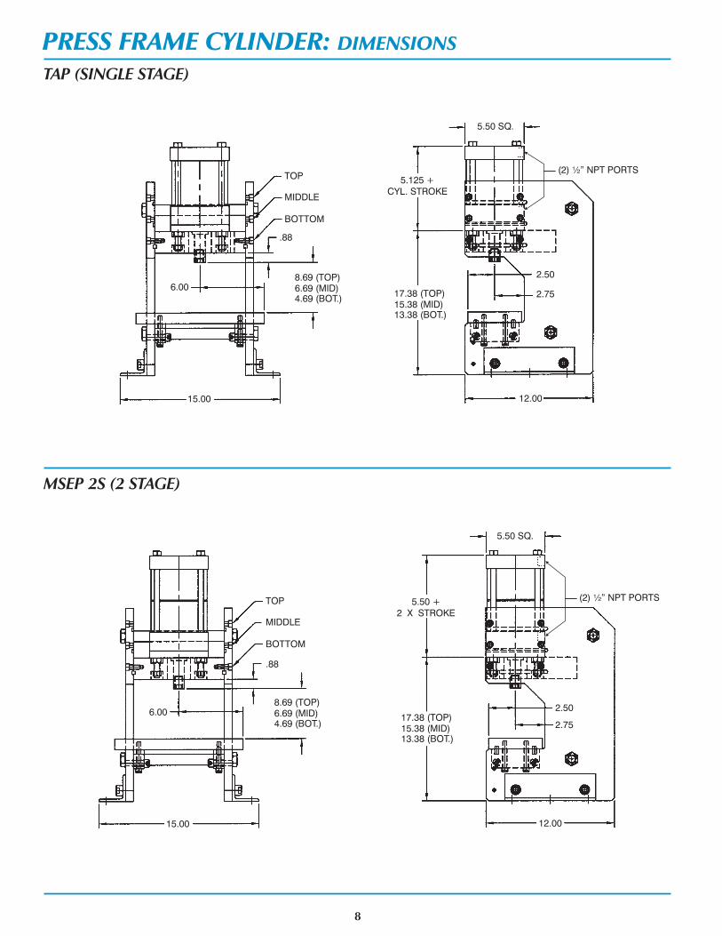
PRESS FRAME CYLINDER: DIMENSIONS
TAP (SINGLE STAGE)
MSEP 2S (2 STAGE)
TOP
MIDDLE
BOTTOM
.88
6.00
15.00
8.69 (TOP)6.69 (MID)4.69 (BOT.)
5.50 +
2 X STROKE
17.38 (TOP)15.38 (MID)13.38 (BOT.)
2.50
2.75
12.00
5.50 SQ.
TOP
MIDDLE
BOTTOM
.88
6.00
15.00
8.69 (TOP)6.69 (MID)4.69 (BOT.)
5.125 +
CYL. STROKE
17.38 (TOP)15.38 (MID)13.38 (BOT.)
2.50
2.75
12.00
5.50 SQ.
(2) ½” NPT PORTS
(2) ½” NPT PORTS

9
PRESS FRAME CYLINDER: DIMENSIONS
MSEP 3S (3 STAGE)
MSEP 4S (4 STAGE)
(2) ½” NPT PORTS
TOP
MIDDLE
BOTTOM
.88
6.00
15.00
8.69 (TOP)6.69 (MID)4.69 (BOT.)
6.75 +
3 X STROKE
17.38 (TOP)15.38 (MID)13.38 (BOT.)
2.50
2.75
12.00
5.50 SQ.
(2) ½” NPT PORTS
TOP
MIDDLE
BOTTOM
.88
6.00
15.00
8.69 (TOP)6.69 (MID)4.69 (BOT.)
8.00 +
4 X STROKE
17.38 (TOP)15.38 (MID)13.38 (BOT.)
2.50
2.75
12.00
5.50 SQ.

10
PRESS FRAME CYLINDER: DIMENSIONS
MSEP 5S (5 STAGE)
TRP (TRIPLE ROD)
TOP
MIDDLE
BOTTOM
.88
6.00
15.00
8.69 (TOP)6.69 (MID)4.69 (BOT.)
9.25 +
5 X STROKE
17.38 (TOP)15.38 (MID)13.38 (BOT.)
2.50
2.75
12.00
5.50 SQ.
(2) ½” NPT PORTS
TOP
MIDDLE
BOTTOM
.75
6.00
15.00
7.81 (TOP)5.81 (MID)3.81 (BOT.)
1.00
5.00 SQ.
5.00 SQ.
3.32 SQ.
(4) ½-20 X 1. DEEP
TAPPED HOLES
TOOLING PLATE DETAIL
5.125 +
CYL. STROKE
17.38 (TOP)15.38 (MID)13.38 (BOT.)
2.50
2.75
12.00
5.50 SQ.
(2) 3/8” NPT PORTS

Worldwide Distribution means there is a Professional DistributorRepresentative nearby – wherever you are – ready to service your needs.
Ask Your Local Distributor About These Other Products:
TRD offers a complete range of custom solutions for youractuator needs.Here are a few examples of actuators developed for OEM applications:
11
2½” Bore (Alum.)Custom 4½” Bore (Steel)Custom 2½”-8” Bore (Steel)Spherical Brg. 1½” Bore (Alum.)Custom
NFPA cylinders with continuous piston rod position sensing.
NFPA cylinders with Pneumatic Position Control System.
Can be used for measuring and gauging applications.
For applications requiring accurate of piston rodpositioning in bore sizes from 1½” to 4”.
Available from 1½” to 8” Bore
control
Request Catalog TRD #PFLF-1004
NFPA Interchangeable Stainless Steel cylindersAvailable from 1½” to 8” Bore
Available from 2” to 8” Bore
Available from 1½” to 6” Bore
Stainless Steel Non-Rotating cylinders
Stainless Steel Multi-Stage force multiplying cylinders
Stainless Steel Air/Oil Tanks and Stainless Steel Accessories
Request Catalog TRD #CAT-TRDSS-704
NFPA Aluminum cylinders
NFPA Aluminum Non-Rotating cylinders
NFPA Electroless Nickel Plated cylinders
Aluminum Multi-Stage force multiplying cylinders
Available from 1½” to 12” Bore
Available from 2” to 12” Bore
Available from 1½” to 12” Bore
Available from 1½” to 8” Bore
Request Catalog TRD #CAT-TRD1-0104

TRD-BTP-0905 ©Copyright 2005 TRD Manufacturing, Inc. All Rights Reserved. Printed in the U.S.A.
TRD DELIVERIES (F.O.B. Factory)
SERIES DELIVERY SCHEDULE
BTP (501 or 502 PRESS FRAME) . . . . . . . . . . . . . . . . . . . . . . . 2-3 DAYSTAP/TRAP (SINGLE STAGE PRESS CYLINDERS). . . . . . . . . . . . 2-3 DAYSMSEP (MULTI-STAGE PRESS CYLINDERS). . . . . . . . . . . . . . . . 3-4 DAYSTRAP-MSE (TRIPLE ROD MULTI-STAGE CYLINDERS). . . . . . . 3-4 DAYS
STANDARD OPTIONS INCLUDED IN ABOVE DELIVERIES
RUSH SERVICES ARE AVAILABLE FOR ALL TRD PRODUCTS.CONTACT YOUR LOCAL TRD DISTRIBUTOR FOR DETAILS.
RUSH SERVICE
YOUR LOCAL DISTRIBUTOR IS:
10914 N. 2ND STREET • MACHESNEY PARK, ILLINOIS 61115-1400
PHONE: (815) 654-7775 • FAX: (815) 654-0690
WEBSITE: WWW.TRDMFG.COM • E-MAIL: [email protected]