HeatStation™ CONDENSING WATER BOILER … and operation... · HeatStation™CONDENSING WATER...
62
34-1161 05/17 HeatStation™ CONDENSING WATER BOILER INSTALLATION & MAINTENANCE MANUAL MODELS HS (1000, 1250, 1500, 1750, 2000) Installation and service must be performed by a qualified service installer, service agency or the gas supplier. IMPORTANT: THIS MANUAL CONTAINS INFORMATION REQUIRED FOR INSTALLATION, OPERATION AND MAINTENANCE OF THIS EQUIPMENT. READ AND FOLLOW THE INFORMATION IN THIS MANUAL AND ALL OTHER PROVIDED INSTRUCTIONS, LABELS AND MARKINGS BEFORE INSTALLING, OPERATING OR SERVICING THIS UNIT. TO THE INSTALLER: After installation, these instructions must be given to the equipment user or left near the appliance. SPECIAL INSTRUCTIONS TO THE OWNER: Retain this manual for future reference. These instructions contain important information that will help you in maintaining and operating this appliance. Riverside Hydronics® 3209 Galvez Avenue Fort Worth, Texas 76111 1-800-990-5918 www.riversidehydronics.com
Transcript of HeatStation™ CONDENSING WATER BOILER … and operation... · HeatStation™CONDENSING WATER...

34-1161 05/17
HeatStation™ CONDENSING WATER BOILER INSTALLATION & MAINTENANCE MANUAL
MODELS HS (1000, 1250, 1500, 1750, 2000)
Installation and service must be performed by a qualified service installer, service agency or the gas supplier. IMPORTANT: THIS MANUAL CONTAINS INFORMATION REQUIRED FOR INSTALLATION, OPERATION AND MAINTENANCE OF THIS EQUIPMENT. READ AND FOLLOW THE INFORMATION IN THIS MANUAL AND ALL OTHER PROVIDED INSTRUCTIONS, LABELS AND MARKINGS BEFORE INSTALLING, OPERATING OR SERVICING THIS UNIT.
TO THE INSTALLER: After installation, these instructions must be given to the equipment user or left near the appliance.
SPECIAL INSTRUCTIONS TO THE OWNER: Retain this manual for future reference. These instructions contain important
information that will help you in maintaining and operating this appliance.
Riverside Hydronics®
3209 Galvez Avenue Fort Worth, Texas 76111 1-800-990-5918 www.riversidehydronics.com
HeatStation™ CONDENSING WATER BOILER
2 34-1161 05/17
TABLE OF CONTENTS
1. Safety Considerations
2. Product Descriptions
3. Boiler Installation
3.1 Checking Equipment Before You Install
3.2 Codes
3.3 Electrical Requirements
3.4 Handling and Locating the Boiler
3.5 Clearances to Combustible Surfaces
3.6 Service Clearances
3.7 Other Codes and Regulatory Clearances and Requirements
4. General Piping Guidelines
4.1 Supply and Return Connections
4.2 Sensor Locations and Thermal Well
4.3 Filling the Boiler
4.4 Building Return Temperature
5. Condensate Drain, Trap & Disposal
5.1 Condensate Neutralization System (optional)
6. Gas Supply and Piping
6.1 Gas Train and Controls Certification
6.2 Gas Control Trains
6.3 Inlet Pressure
6.4 Manifold Pressure
6.5 Gas Piping Size
6.6 Appliance Isolation during Gas Supply Piping Pressure Test
6.7 Gas Connection
7. Combustion and Ventilation Air
7.1 Equipment Located in Confined Spaces
7.2 Maximum Allowed Remote Combustion Air Inlet Length
7.3 Remote Combustion Air Termination
7.4 Vertical or Horizontal Remote Air Duct Termination
7.5 Combining Remote Air Ducting
7.6 Air Filtratopm
8. Venting
8.1 Vent Material Selection
8.2 Vent Installation – General
8.2.1 Maximum Vent Length (Equivalent length)
8.2.2 Vertical or Horizontal Vent Termination
8.2.3 Combining Category IV Vents
8.2.4 Connecting to an Existing Vent System
8.3 PVC Vent Installation
8.4 CPVC Vent Installation
8.5 Polypropylene or Stainless Steel Vent Installation
9. Operating and Safety Controls
9.1 Pressure Relief Valve(s)
9.2 Flow Switch
9.3 Blocked Flue Switch
9.4 Electronic Low Water Cut-off
9.5 Operating Temperature Control
9.6 High Water Temperature Limit
10. EOS (Electronic Operating System)
10.1 Touch Screen User Interface

HeatStation™ CONDENSING WATER BOILER
3 34-1161 05/17
10.2 Status Field Display
10.3 Operational Sequence Field Display
10.4 View Menu (Home Screen - Default Display)
10.5 Control System Menus
10.6 Selecting the Correct Applicationi Mode
10.7 Control Setting for Hydronic System Design
10.8 Selecting the Supply or Return Sensor for Single Boiler Primary Only System
10.9 Changing the Operating Target
10.10 Setting the Real Time Clock
10.11 Scheduled Setback
10.12 Using the Manual Override Menu
10.13 Potentiometer (Operating Set Point for Standalone Operation)
10.14 Outdoor Reset Operation
10.15 Multiple Boiler Cascade System
10.16 EMS Control
10.17 PIM DIP Switch Selectable Options
10.18 Using Tool Box Menu
11. Communications And Diagnostics
11.1 Indicators
11.2 Alarm Messages – Diagnostic Codes (Flashes)
11.3 Replacing the Fuse
11.4 Self-Check / Control Failure
11.5 System Safety Checks
11.6 Flame Current Measurements
11.7 Non-Volatile Lockout / Manual Reset
11.8 ID Card
12. Remote Connections – Terminal Strip
12.1 Making BMS/BAS Remote Connection for Analog and Binary Signals
12.2 Terminal Functions
12.3 Internal Component Terminal Functions and Primary Pump Control
12.4 Connecting Isolation Valves
13. Sequence of Operation
14. Initial Startup
14.1 Initial Startup Requirements
14.2 Tools and Instrumentation Required
14.3 Resources
14.4 On Site Considerations
14.5 Pre-Startup Checklist
14.6 Startup Procedure
14.7 Potentiometer
15. Troubleshooting Procedure
15.1 General Troubleshooting
15.2 LED Error Code Listing
16. Replacement Parts
16.1 Blower & Burner Assembly
16.2 Control Panel Components
16.3 Gas Train Assembly
16.4 Component Wiring Details
17. Periodic Maintenance
18. Recommended Maintenance Schedule
Warranty forms ship separately with each product.
HeatStation™ CONDENSING WATER BOILER
4 34-1161 05/17
1 SAFETY CONSIDERATIONS
WARNING: If the information in the supplied manual(s) is not followed exactly, a fire, explosion or exposure to hazardous materials may result, causing property damage, personal injury or death. AVERTISSEMENT. Assurez-vous de bien suivre les instructions données dans cette notice pour réduire au minimum le risque d’incendie ou d’explosion ou pour éviter tout dommage matérial, toute blessure ou la mort
FOR YOUR SAFETY
Do not store or use gasoline or other flammable vapors or liquids in the vicinity of this or any other appliance.
Ne pas entreposer ni utiliser d’essence ou ni d’autres vapeurs ou liquides inflammables à proximité de cet appareil ou de
tout autre appareil.
WHAT TO DO IF YOU SMELL GAS
Do not try to light any appliance.
Do not touch any electric switch; do not use any phone in your building.
Immediately call your gas supplier from a location away from your building and the smell of gas. Follow the gas
supplier's instructions.
If you cannot reach your gas supplier, call the fire department.
QUE FAIRE SI VOUS SENTEZ UNE ODEUR DE GAZ:
Ne pas tenter d’allumer d’appareil.
Ne touches à aucun interrupteur; ne pas vous server des téléphones se trouvant dans le bâtiment.
Appelez immediatement votre fournisseur de gaz depuis un voisin. Suivez les instructions de fournisseur.
Si vous ne pouvez rejoinder le fournisseur, appelez le service de incendies.
Installation and service must be performed by a qualified installer, service agency or the gas supplier. L’installation et l’entretrien doivent être assurés ou un service d’entretien qualifié ou par le fournisseur de gaz.
This product contains, or may come to contain materials that have been identified as carcinogenic, or possibly carcinogenic to humans. Before installing, servicing or removing this product, read and follow the supplied instructions. Clearance in accordance with the local installation codes and the requirements of the gas supplier. Dégagement conforme aux codes d’installation locaux et aux exigencies du foumisseunde gaz. Should overheating occur or the gas supply fail to shut off, turn off the manual gas control valve to the appliance. En cas de surchauffe ou si l’alimentation en gas ne s’arrête pas, fermez manuellement le robinet d’arrêt de l’admission de gaz.
WARNING: Installation and service must be performed by a qualified installer, service agency or the gas supplier, who must read and follow the supplied instructions before installing, servicing or removing this appliance. Refer to the information contained in this manual. Improper installation, adjustment, alteration, service or maintenance can cause property damage, personal injury, exposure to hazardous materials or death.
WARNING: Do not use this appliance if any part has been under water. Immediately call a qualified service technician to inspect the unit and to replace any part of the control system, all gas controls and all other items affecting safe appliance operation and which has been under water.
AVERTISSEMENT: N’utilisez pas cet appareil s’il a été plongé dans l’eau, même partiellement. Faites inspecter l’appareil par un technicien qualifé et remplacez toute partie du système de contrôle et toute commande qui ont été plongés dans l’eau.
WARNING: In an emergency shut the main gas supply valve to the appliance from a location safely away from the emergency. Failure to follow these instructions can cause property damage, personal injury, and exposure to hazardous materials or death.
HeatStation™ CONDENSING WATER BOILER
5 34-1161 05/17
PRODUCT SAFETY INFORMATION REFRACTORY CERAMIC FIBER PRODUCT WITH CRYSTALLINE SILICA
WARNING: This product contains or may come to contain crystalline silica, which has been identified by the International Agency for Research on Cancer (IARC) as carcinogenic to humans. This product also contains refractory ceramic fibers, which have been identified by the IARC as possibly carcinogenic to humans. Avoid breathing fiber particulates and dust.
RISKS:
Air borne fibrous insulation is a possible cancer hazard by inhalation.
Airborne crystalline silica may cause silicosis (lung disease) by inhalation.
May cause temporary irritation to eyes, skin, and respiratory tract.
PRECAUTIONARY MEASURES:
Minimize airborne fibers with engineering controls.
Use NIOSH/MSHA approved respirators as required (see MSDS).
Wear long sleeved, loose-fitting clothing, eye protection and gloves.
FIRST AID MEASURES: (If any of the irritations listed persists, seek medical attention)
Eyes: Flush with water.
Skin: Wash with soap and warm water.
Ingestion: Do not induce vomiting. Get medical attention if gastrointestinal symptoms develop.
Inhalation: Remove to fresh clean air.
WARNING: If you are unfamiliar with the safe handling of refractory ceramic fiber products, or if you wish additional information prior to beginning any disassembly of the water heater or boiler that might expose refractory ceramic fiber materials, contact: Unifrax Corporation, 2351 Whirlpool Street, Niagara Falls, NY 14305-2413, 1-800-322-2293.
IDENTIFICATION OF REFRACTORY CERAMIC FIBER MATERIALS (RCF):
The burner assembly utilizes RCF material. (The RFC materials are located within the product and not generally exposed except during service, disassembly or assembly.)

HeatStation™ CONDENSING WATER BOILER
6 34-1161 05/17
2 PRODUCT DESCRIPTIONS Component, Controls and Connection Locations (Locations May Vary)
Dimensional information for HS 1000, HS 1250, and HS 1500

HeatStation™ CONDENSING WATER BOILER
7 34-1161 05/17
Dimensional information for HS 1750 and HS 2000
HeatStation™ CONDENSING WATER BOILER
8 34-1161 05/17
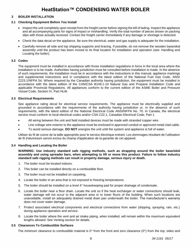
3 BOILER INSTALLATION
3.1 Checking Equipment Before You Install
Inspect the unit completely upon receipt from the freight carrier before signing the bill of lading. Inspect the appliance and all accompanying parts for signs of impact or mishandling. Verify the total number of pieces shown on packing slips with those actually received. Contact the freight carrier immediately if any damage or shortage is detected.
Check the data decal on the appliance. Be sure the electrical, water and gas supply is adequate for the installation.
Carefully remove all side and top shipping supports and bracing. If possible, do not remove the wooden base/skid assembly until the product has been moved to its final location for installation and operation (see: Handling and Locating the boiler).
3.2 Codes
The equipment must be installed in accordance with those installation regulations in force in the local area where the installation is to be made. Authorities having jurisdiction must be consulted before installation is made. In the absence of such requirements, the installation must be in accordance with the instructions in this manual, appliance markings and supplemental instructions and in compliance with the latest edition of the National Fuel Gas Code, ANSI Z223.1/NFPA 54. Where required by the Canadian authority having jurisdiction, the equipment must be installed in accordance with the latest edition of the CAN/CSA B149.1-10 Natural Gas and Propane Installation Code and applicable Provincial Regulations. All appliances conform to the current edition of the ASME Boiler and Pressure Vessel Code, Section IV, Part HLW.
3.3 Electrical Requirements
See appliance rating decal for electrical service requirements. The appliance must be electrically supplied and grounded in accordance with the requirements of the authority having jurisdiction or, in the absence of such requirements, with the latest edition of the National Electrical Code ANSI/NFPA No. 70. In Canada, the electrical service must conform to local electrical codes and/or CSA C22.1, Canadian Electrical Code, Part 1.
All wiring between the unit and field installed devices must be made with stranded copper wire.
Line voltage wire exterior to the appliance must be enclosed in approved conduit or approved metal clad cable.
To avoid serious damage, DO NOT energize the unit until the system and appliance is full of water.
Utiliser du fil de cuivre de la taille appropriée pour le service électrique entrant. Les dommages résultant de l'utilisation de fil d'aluminium seront exclus du champ d'application de la garantie de cet appareil.
3.4 Handling and Locating the Boiler
WARNING: Use industry standard safe rigging methods, such as strapping around the boiler base/skid assembly and using spreader bars, when attempting to lift or move this product. Failure to follow industry standard safe rigging methods can result in property damage, serious injury or death.
1. The boiler must be located indoors.
2. This boiler can be installed directly on a combustible floor.
3. The boiler must not be installed on carpeting.
4. Locate the boiler in an area that is not exposed to freezing temperatures.
5. The boiler should be installed on a level 4" housekeeping pad for proper drainage of condensate.
6. Locate the boiler near a floor drain. Locate the unit so if the heat exchanger or water connections should leak, water damage will not occur to the adjacent area or to lower floors of the building. When such locations are unavoidable, install an adequately drained metal drain pan underneath the boiler. The manufacturer’s warranty does not cover water damage.
7. Protect associated electrical components and electrical connections from water (dripping, spraying, rain, etc.) during appliance operation and service.
8. Locate the boiler where the vent and air intake piping, when installed, will remain within the maximum equivalent lengths allowed. See Venting section for details.
3.5 Clearances To Combustible Surfaces
The minimum clearance to combustible material is 0" from the front and zero clearance (0") from the top, sides and

HeatStation™ CONDENSING WATER BOILER
9 34-1161 05/17
back of the boiler. The HeatStation can be installed directly on a combustible floor, but not on carpet.
Distance minimale aux matériaux combustibles est égale à zéro (0 cm) sur les haut, côtés et à l'arrière, avant les 61 cm et peut être installé directily sur un plancher combustible.
3.6 Service Clearances
Additional clearance beyond the minimum required to combustible material should be considered to facilitate easy access for inspection and service of items such as the burner, gas controls and plumbing connections. Also allow sufficient space for installing and servicing building water, gas, vent, combustion air, electrical, pump and other auxiliary/optional equipment and connections.
3.7 Other Code and Regulatory Clearances and Requirements
Additional clearance beyond the minimum required to combustible materials and service recommendations may be required to comply with local, state or national codes and regulations. It is to the responsibility of the installer to comply with these requirements. Examples of codes or regulations that may apply are the National Electric Code, State/Regional/National drain water and flue emissions regulations, the National Fuel Gas Code, Building Construction and Safety Codes, the Americans with Disabilities Act (ADA) and ”Safety Code for Controls and Safety Devices for Automatically Fired Boilers” (CSD-1) and other applicable Boiler Installation Code and Regulatory requirements.
4 GENERAL PIPING GUIDELINES
4.1 Supply and Return Connections
1. Connect the boiler system return piping (water to be heated) to the “Return” fitting located near the bottom and rear
of the boiler.
2. Connect the system supply piping (hot water out of the unit)) to the “Supply” fitting located near the top and rear of
the boiler.
3. Install shut-off valves and unions on the Return and Supply piping for servicing. Use caution when threading pipe
nipples into tank connections to prevent cross threading, or over-tightening. Always use a back-up wrench on tank
nipples when tightening unions, valves, etc.
4. Take those steps necessary to avoid the risk of boiler water freezing in the boiler or system piping (such as adding
glycol (up to 50%), insulating pipes, heat trace, etc.).
5. Pipe the drain valve to a suitable open drain capable of receiving discharge temperatures up to 212ºF.

HeatStation™ CONDENSING WATER BOILER
10 34-1161 05/17
IMPORTANT: Do not use the plumbing connected to the appliance as a ground for welding or any other purpose.
Example of a Single Boiler, Primary Only Installation
Example of a Multi Boiler, Primary Only Installation

HeatStation™ CONDENSING WATER BOILER
11 34-1161 05/17
Example of a Single Boiler, Primary/Secondary Only Installation
Example of a Multi Boiler, Primary/Secondary Only Installation

HeatStation™ CONDENSING WATER BOILER
12 34-1161 05/17
4.2 Sensor Locations and Thermal Well
The selection of the hydronic system design is explained in detail in Section 10 “Control Settings for Hydronic System Design”.
The EOS control system on HeatStation comes configured for the Multi Boiler Primary/Secondary hydronic system. The system sensor will automatically be selected for system temperature regulation. The system sensor along with a thermal well is provided and wired to the control board (J2-5 & J2-4 common). If the system sensor is not to be used for control, it can be left uninstalled. Only one system sensor is required when the Cascade function is enabled. The PIPING parameter = P/S (SETUP MENU). In Cascade, the system sensor is installed on the MASTER boiler.
When HeatStation is applied in a Multi Boiler Primary Only hydronic system, the system sensor will also be used for system temperature regulation. The system sensor along with the provided thermal well should be installed in the main supply plumbing. Only one system sensor is required when the Cascade function is enabled. In Cascade, the system sensor is installed on the MASTER boiler. Isolation valves are recommended for this system. When PIPING parameter = VALV (SETUP MENU), the EOS will control the isolation valves. See the piping illustration in Section 4.
In a Single Boiler Primary Only installation the PIPING parameter = PAR (SETUP MENU). In this configuration HeatStation can use either the supply sensor located in the upper piping manifold or the return sensor located in the lower for operation as needed. As the HeatStation is shipped, the controlling sensor is the supply sensor. If return sensor control is preferred, refer to Section 10 for instructions on how to configure the EOS control system for your hydronic system and select the desired sensor location.
4.3 Filling the Boiler
1. Fill the system with water. To be sure that the unit is not “air bound,” open the relief valve. Leave the valve open until a steady flow of water is observed. Close the valve and complete filling the system.
2. In hard water areas, fill water should receive water treatment to reduce the introduction of minerals into the system. Excessive buildup of minerals in the heat exchanger can cause a non-warrantable failure.
3. Make sure there are no system leaks. DO NOT use petroleum based stop-leak products. All system leaks must be repaired. The constant addition of make-up water to a closed loop boiler system can cause minerals to collect in the heat exchanger. Excessive buildup of minerals in the heat exchanger can cause a non-warrantable failure.
4. For systems requiring freeze protection, use only hydronic system antifreeze with a maximum concentration of 50%. Follow the glycol manufacturer’s instructions. DO NOT use uninhibited or automotive type antifreeze.
4.4 Building Return Temperature
The HeatStation can safely use plastic venting in systems that use colder building return water throughout the year. Higher building return water temperatures, or systems which reset to higher temperatures in cold weather may require the use of stainless steel venting. See Section 8 “Venting” regarding the selection of vent materials based on maximum operational temperatures.

HeatStation™ CONDENSING WATER BOILER
13 34-1161 05/17
5 CONDENSATE DRAIN, TRAP & DISPOSAL
The HeatStation boiler produces a significant amount of condensate. The condensate drain is under slightly positive
flue pressure; therefore the 1" CPVC condensate trap assembly supplied with the product must always be used. This
trap is sized and designed to create a liquid barrier to prevent flue gases from escaping through the condensate drain into the installed space. Prior to startup or after extended periods of non-use, manually fill the trap with water before operating the boiler.
WARNING: The trap included with this unit must be installed and maintained as described in these instructions and must be included as part of the condensate piping system. This trap is required to keep potentially hazardous products of combustion from continually entering the installed space where the condensate piping terminates. Failure to properly install this trap can cause, personal injury, exposure to hazardous materials or death.
1. The condensate trap assembly is disconnected from the boiler’s condensate drain, at the union, prior to shipping.
2. The condensate drain exits the flue collector at the bottom rear of the boiler.
Connect the 1" CPVC union on the trap assembly to the CPVC union on the condensate drain. Rotate the trap assembly from the union downward, and rotate the outlet vertically to maintain a three (3) inch distance from the hose connector to the floor.
IMPORTANT: Do not rotate the trap “U” bend toward the ceiling. Do not use tools to tighten the CPVC union. Hand-tighten the CPVC union to seat the internal gasket.
3. Connect a 3/4" ID heavy wall Vinyl tubing rated for 170ºF or higher condensate drain line, or a Condensate Neutralization System to the barbed hose connection located at the end of the condensate trap. Alternatively, 3/4" PVC piping may be used for the condensate drain line.
IMPORTANT: Do not crimp or kink the flexible hose when routing to drain.
4. All piping from the condensate trap to the suitable drain must remain below the top of the properly installed condensate trap outlet.
5. Do not combine condensate drains from multiple condensing appliances into a single drain line. Route each drain line into a drain suitable for condensate and make certain the end of the drain lines are not submerged or otherwise blocked.
6. All condensate plumbing must be protected from freezing. Do not locate the condensate piping such that an ice dam of frozen condensate can block condensate from leaving the outlet.
7. The condensate is only slightly acidic (3-5 PH), however, local codes may require it to be neutralized prior to entering the drainage system. An optional, field installed, Condensate Neutralization System is available from the factory.
Condensate Trap without Optional Condensate Neutralization System
5.1
HeatStation™ CONDENSING WATER BOILER
14 34-1161 05/17
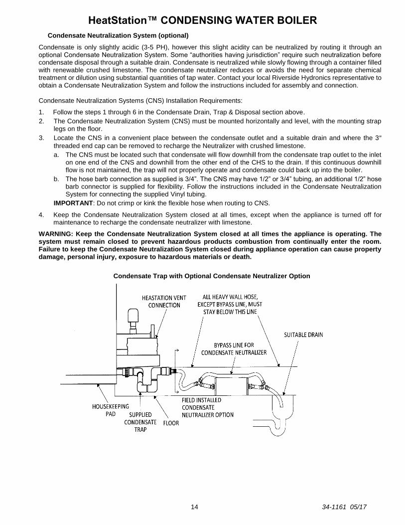
Condensate Neutralization System (optional)
Condensate is only slightly acidic (3-5 PH), however this slight acidity can be neutralized by routing it through an optional Condensate Neutralization System. Some “authorities having jurisdiction” require such neutralization before condensate disposal through a suitable drain. Condensate is neutralized while slowly flowing through a container filled with renewable crushed limestone. The condensate neutralizer reduces or avoids the need for separate chemical treatment or dilution using substantial quantities of tap water. Contact your local Riverside Hydronics representative to obtain a Condensate Neutralization System and follow the instructions included for assembly and connection. Condensate Neutralization Systems (CNS) Installation Requirements:
1. Follow the steps 1 through 6 in the Condensate Drain, Trap & Disposal section above.
2. The Condensate Neutralization System (CNS) must be mounted horizontally and level, with the mounting strap legs on the floor.
3. Locate the CNS in a convenient place between the condensate outlet and a suitable drain and where the 3" threaded end cap can be removed to recharge the Neutralizer with crushed limestone.
a. The CNS must be located such that condensate will flow downhill from the condensate trap outlet to the inlet on one end of the CNS and downhill from the other end of the CHS to the drain. If this continuous downhill flow is not maintained, the trap will not properly operate and condensate could back up into the boiler.
b. The hose barb connection as supplied is 3/4”. The CNS may have 1/2” or 3/4” tubing, an additional 1/2” hose barb connector is supplied for flexibility. Follow the instructions included in the Condensate Neutralization System for connecting the supplied Vinyl tubing.
IMPORTANT: Do not crimp or kink the flexible hose when routing to CNS.
4. Keep the Condensate Neutralization System closed at all times, except when the appliance is turned off for maintenance to recharge the condensate neutralizer with limestone.
WARNING: Keep the Condensate Neutralization System closed at all times the appliance is operating. The system must remain closed to prevent hazardous products combustion from continually enter the room. Failure to keep the Condensate Neutralization System closed during appliance operation can cause property damage, personal injury, exposure to hazardous materials or death.
Condensate Trap with Optional Condensate Neutralizer Option

HeatStation™ CONDENSING WATER BOILER
15 34-1161 05/17
6 GAS SUPPLY AND PIPING
Verify the type of gas specified on rating plate is supplied to the unit. This unit is orificed for operation up to 2000 feet altitude. Appliance Btu/h input derates 4% per 1000 feet elevation above sea level. Consult Factory for installations above 2000 feet elevation.
6.1 Gas Train and Controls Certification
NOTE: The gas train and controls assembly provided on this unit have been tested under the applicable Nationally Recognized Standard to comply with safety and performance criteria such as ignition, combustion and safety shutdown operation.
6.2 Gas Control Trains
All models include the following gas control train components: manual shutoff valve, a combination gas valve containing two safety shutoff valves, an internally vent limited zero governor type regulator, a manual test valve and manifold pressure taps, and high and low gas pressure switches.
WARNING: Do not adjust or remove any screws or bolts on gas train control components which are secured with a red or blue sealing compound. In addition to voiding warranties and certification listings, such adjustment or disassembly can cause improper operation which could result in property damage, personal injury or death.
6.3 Inlet Pressure
Measure at the inlet pressure tap located at the main gas cock. The inlet pressure must remain within the minimum and maximum values while the unit is at rest and while the unit is operating at maximum firing rate.
6.4 Manifold Pressure
Measure at the pressure tap located downstream side of the manual valve closest to the burner. The rated manifold pressure appears on the product data label located near the front of the appliance.
6.5 Gas Piping Size
The following table identifies the gas connection size.
MODEL SIZE NPT
1000 & 1250 HS 1"
1500, 1750 & 2000 HS 1½"
Do not use the gas pipe connection size to determine the gas supply piping. Designing and sizing a gas supply piping system requires consideration of many factors and must be done by a gas supply piping expert. Always follow NFPA 54 National Fuel Gas Code for gas pipe sizing and gas pipe system design. The following charts provide examples of some of the information used by the gas supply piping expert to determine proper pipe sizes. Use the values in the following table to add the equivalent straight pipe for each elbow or tee to obtain the total distance from the meter:
INLET PRESSURE NAT. GAS Propane
Maximum Static Pressure (Inches-Water Column) 14.0" 13"
Minimum Flow Pressure (Inches-Water Column) 3.5" 8"
CONVERT FITTINGS TO EQUIVALENT STRAIGHT PIPE*
Diameter Fitting (inches) ¾" 1" 1¼" 1½" 2" 3" 4" 5"
Equivalent Length of Straight Pipe (feet) 2' 2' 3' 4' 5' 10' 14' 20'
HeatStation™ CONDENSING WATER BOILER
16 34-1161 05/17
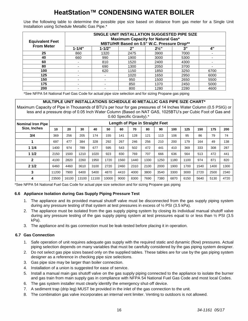
Use the following table to determine the possible pipe size based on distance from gas meter for a Single Unit Installation using Schedule Metallic Gas Pipe.*
*See NFPA 54 National Fuel Gas Code for actual pipe size selection and for sizing Propane gas piping
*See NFPA 54 National Fuel Gas Code for actual pipe size selection and for sizing Propane gas piping
6.6 Appliance Isolation during Gas Supply Piping Pressure Test
1. The appliance and its provided manual shutoff valve must be disconnected from the gas supply piping system during any pressure testing of that system at test pressures in excess of ½ PSI (3.5 kPa).
2. The appliance must be isolated from the gas supply piping system by closing its individual manual shutoff valve during any pressure testing of the gas supply piping system at test pressures equal to or less than ½ PSI (3.5 kPa).
3. The appliance and its gas connection must be leak-tested before placing it in operation.
6.7 Gas Connection
1. Safe operation of unit requires adequate gas supply with the required static and dynamic (flow) pressures. Actual piping selection depends on many variables that must be carefully considered by the gas piping system designer.
2. Do not select gas pipe sizes based only on the supplied tables. These tables are for use by the gas piping system designer as a reference in checking pipe size selections.
3. Gas pipe size may be larger than boiler connection.
4. Installation of a union is suggested for ease of service.
5. Install a manual main gas shutoff valve on the gas supply piping connected to the appliance to isolate the burner and gas train from main supply gas in compliance with NFPA 54 National Fuel Gas Code and most local Codes.
6. The gas system installer must clearly identify the emergency shut-off device.
7. A sediment trap (drip leg) MUST be provided in the inlet of the gas connection to the unit.
8. The combination gas valve incorporates an internal vent limiter. Venting to outdoors is not allowed.
Equivalent Feet
From Meter
SINGLE UNIT INSTALLATION SUGGESTED PIPE SIZE Maximum Capacity for Natural Gas*
MBTU/HR Based on 0.5" W.C. Pressure Drop**
1-1/4" 1-1/2" 2" 2½" 3" 4" 25 860 1320 2475 3900 7000 -
40 660 990 1900 3000 5300 -
60 - 810 1520 2400 4300 -
80 - 690 1300 2050 3700 -
100 - 620 1150 1850 3250 6700
125 - - 1020 1650 2950 6000
150 - - 950 1500 2650 5500
175 - - 850 1370 2450 5000
200 - - 800 1280 2280 4600
MULTIPLE UNIT INSTALLATIONS SCHEDULE 40 METALLIC GAS PIPE SIZE CHART*
Maximum Capacity of Pipe in Thousands of BTU’s per hour for gas pressures of 14 Inches Water Column (0.5 PSIG) or less and a pressure drop of 0.05 Inch Water Column (Based on NAT GAS, 1025BTU’s per Cubic Foot of Gas and
0.60 Specific Gravity).*
Nominal Iron Pipe Size, Inches
Length of Pipe in Straight Feet
10 20 30 40 50 60 70 80 90 100 125 150 175 200
3/4 369 256 205 174 155 141 128 121 113 106 95 86 79 74
1 697 477 384 328 292 267 246 256 210 200 179 164 49 138
1 1/4 1400 974 789 677 595 543 502 472 441 410 369 333 308 287
1 1/2 2150 1500 1210 1020 923 830 769 707 666 636 564 513 472 441
2 4100 2820 2260 1950 1720 1560 1440 1330 1250 1180 1100 974 871 820
2 1/2 6460 4460 3610 3100 2720 2460 2310 2100 2000 1900 1700 1540 1400 1300
3 11200 7900 6400 5400 4870 4410 4000 3800 3540 3300 3000 2720 2500 2340
4 23500 16100 13100 11100 10000 9000 8300 7690 7380 6870 6150 5640 5130 4720

HeatStation™ CONDENSING WATER BOILER
17 34-1161 05/17
7 COMBUSTION AND VENTILATION AIR
Provisions for adequate combustion and ventilation air to the mechanical room must be in accordance with Section “Air for Combustion and Ventilation” in the latest edition of the NFPA 54 National Fuel Gas Code, ANSI Z223.1 and/or CAN/CSA B149, Installation Codes or applicable provisions of the local building codes. Any method addressed in NFPA 54 National Fuel Gas Code section “Air for Combustion and Ventilation is acceptable and several are outlined below.
7.1 Equipment Located In Confined Spaces
Equipment located in confined spaces requires two openings, one commencing within 12" (30.5 cm) from the top of
the enclosure/room and one commencing within 12" from bottom of the enclosure/room to assure adequate
combustion air and proper ventilation. The total input of all gas utilization equipment installed in the room must be used to determine the required minimum air volume needed for combustion, ventilation and dilution of flue gasses. Also consider makeup air requirements from other equipment within the mechanical room or other rooms that are pressure connected with the mechanical room. Some examples of other makeup air requirements are from kitchen exhaust hoods, clothes dryers, powered exhaust fans, etc. When using room air, it is important to ensure the combustion air vent is clear of obstructions, protected from accidental blockage, and protected from airborne debris. A standard vent cap can be used.
All Air From Outdoors:
Each opening requires a minimum free area of 1 square inch per 4000 Btu/hr of the total input rating of all appliances in the enclosure, if directly communicating with the outdoors or communicating to the outdoors through vertical ducts.
Each opening requires a minimum free area of 1 square inch per 2000 Btu/hr of the total input rating of all appliances in the enclosure, if communicating with the outdoors through horizontal ducts.
All Air From Inside The Building:
Follow the requirements of NFPA 54 National Fuel Gas Code, ANSI Z223.1 section “Indoor Combustion Air.”
Combination Of Air From The Indoors And From The Outdoors:
Follow the requirements of NFPA National Fuel Gas Code, ANSI Z223.1 section “Combination Indoor and Outdoor Combustion Air.”
From Outdoors Through One Opening:
Follow the requirements of NFPA National Fuel Gas Code, ANSI Z223.1 section “One Permanent Opening Method.”
Remote Air Intake System:
This unit may be installed with a remote air intake system which uses a make-up air duct to draw combustion air directly from outdoors. Combustion air piping must be supported to prevent transferring any load (weight or twisting moment) on the appliance remote air connection. Load imparted by improperly supported and constrained remote air piping can damage the burner, which could prevent the boiler from operating. Failure to properly support the combustion air supply piping can result in unwarranted damage to the boiler.
WARNING: Adequate clean combustion air must be provided to the appliance. The appliance must never operate under a negative pressure. Particular care must be taken when exhaust fans, compressors, air handling units, etc. may rob air from the appliance. The combustion air supply must be completely free of any chemicals or fumes, which may be corrosive to the appliance. Some common chemical fumes to avoid are fluorocarbons and other halogenated compounds, most commonly present as refrigerants or solvents, such as Freon, trichloroethylene, perchlorethylene, chlorine, etc. These chemicals, when in contact with the equipment or when burned, form acids which quickly attack the tubes, flue collector, stack and other appliance and auxiliary equipment. Failure to provide adequate clean combustion air or operating under negative pressure can cause premature, unwarranted product failure or unsafe operation producing carbon monoxide that could escape into the building. Exposure to carbon monoxide can lead to personal injury or death.

HeatStation™ CONDENSING WATER BOILER
18 34-1161 05/17
7.2 Maximum Allowed Remote Combustion Air Inlet Length (Equivalent Length)
A vertical or horizontal remote air inlet system can be connected to this appliance without modification. The maximum length of field supplied single wall pipe, such as galvanized ventilation pipe, is shown in the chart below titled Maximum Air Inlet Duct Equivalent Length. Use metal tape or RTV sealant to seal each pipe joint.
Maximum Allowable Equivalent Duct Length / Max Elbows
Duct Size 6″ Duct 8″ Duct
Max Equivalent Length all Models 230 feet/8 350 feet/8
To determine the maximum straight length of duct allowed, use the Duct Fitting Equivalent Length chart below to find the total equivalent length for all duct fittings in your combustion air system. Then subtract this number of feet from the total equivalent length allowed in Maximum Air Inlet Duct Equivalent Length chart above. The sum of this calculation is the maximum length of straight duct allowed. If a longer length is required, repeat the calculation using a larger duct size. No additional deduction is required for the addition of the duct system terminal.
Duct Pipe: 6″ Duct 8″ Duct
90º Elbow 20 feet 10 feet
90º Long Radius Elbow 12 feet 6 feet
45º Elbow 12 feet 6 feet
The following remote air duct information is provided for use in design calculations, if needed.
Remote Air Duct Specifications
Input MBtu/h Required Air (SCFM)
1000 220
1250 275
1500 330
1750 385
2000 440
7.3 Remote Combustion Air Termination
A suitable remote air termination must be used to prevent water, debris, animals or obstructing material from entering the remote air supply.
7.4 Vertical or Horizontal Remote Air Duct Termination
Air inlet must be located no less than 3 feet (0.91m) below the exhaust terminal if they are within 10 feet (3.05 m) of each other, unless the flue outlet terminates with a straight discharge. If the flue outlet terminates with a straight discharge, the air inlet can be located no less than 18 inches (0.46m) below the exhaust terminal.
If terminating through the roof, the air inlet must terminate at least 12 inches (0.3 m) above roof level and at least 12 inches (0.3 m) above snow levels.
If terminating through a sidewall, the air inlet must terminate at least 12 inches (0.3 m) above grade and/or at least 12 inches (0.3 m) above possible snow levels.
Vertical Remote Air Horizontal Remote Air
* When flue outlet is terminated with a straight discharge, separation of terminations must be a minimum of 18″.

HeatStation™ CONDENSING WATER BOILER
19 34-1161 05/17
7.5 Combining Remote Air Ducting
Each boiler MUST have separate intake piping, unless the air inlet piping, exhaust duct and other system considerations have been fully evaluated and a combined duct system designed by one of the duct design firms identified a. Before operation of a combined remote air ducting system, all of the duct design firm’s system installation and operation requirements must be in place, their instructions followed and the system must be properly maintained.
Combined HeatStation air intake piping must incorporate a variable speed blower capable of providing and regulating positive pressure air supplied to all boilers in the system. The pressure of the supplied air must not be less than 0.0″ W.C. and must not exceed 0.25″ W.C.
The common combustion air supply system must be interlocked, so the boilers will not begin operation until the common combustion air supply is proved to be within the range of 0.0 to 0.25″ W.C. See Section on Remote Connections for a discussion of how to connect the proving circuit.
WARNING: Do not combine remote air ducting of multiple appliances into a single remote air duct unless the combined remote air ducting system has been evaluated and designed by a specified duct design firm and the combined remote air duct system is installed, operated and maintained following instructions from that firm. Combining remote air ducting without following these requirements can result in failure of the boiler and venting system and/or exposure to carbon monoxide and can result in property damage, personal injury or death.
7.6 Air Filtration
The field installed optional air inlet filter box must be attached to the combustion air inlet on any appliance located where it is exposed to dusty, dirty or lint filled combustion air. Replace the filter on a 3 to 6 month schedule, or more often, based on severity of contamination Inadequate combustion air or non-combustible particulate matter such as dust, dirt, dryer lint, concrete dust, dry wall dust or the like can be drawn in with combustion air and block burner ports. This can cause unreliable operation and non-warrantable failures. When the optional field installed filter box is required, do not operate the appliance without a suitable filter. See the following illustration for filter and filter box kit part numbers and installation instructions.

HeatStation™ CONDENSING WATER BOILER
20 34-1161 05/17
8 VENTING
All HeatStation models use the positive pressure generated by the burner system blower to push combustion products out of the vent. Since the vent system is under positive pressure and must be capable of containing condensate, it must be constructed using schedule 40 solid PVC or CPVC pipe or using a Polypropylene or Stainless Steel venting system (single or double wall) listed by ETL, UL, ULC or CSA for Category IV positive pressure gas appliance venting. Do not use ABS pipe and do not use PVC or CPVC pipe with cell/foam type construction (such as “CellCore”) or other non-solid PVC or CPVC plastic pipe. WARNING: Vent piping must be supported to prevent transferring load to the vent connection. Failure to properly support vent piping can damage the vent connection which can result in failure of the venting system and/or exposure to carbon monoxide or other toxic fumes, which can result in property damage, personal injury or death.
Chaudières HeatStation sont conçus pour fonctionner avec le PVC, CPVC ou en polypropylène ou simple ou double paroi en acier inoxydable système indiqué par ETL, UL, ULC ou CSA pour la catégorie IV pression positive appareil à gaz évacuation de ventilation. Ne sélectionnez pas la taille du tuyau de ventilation basée uniquement sur le diamètre raccord de l'appareil.
WARNING: Use only solid PVC or CPVC pipe or use a Polypropylene or Stainless Steel venting (single or double wall) system listed by a nationally recognized testing laboratory for Category IV positive pressure gas appliance venting. Use of ABS pipe, or use of PVC or CPVC pipe with cell/foam type construction or use of use of venting materials other than specified in these instructions can result in failure of the venting system and/or exposure to carbon monoxide or other toxic fumes, which can result in property damage, personal injury or death.
8.1 Vent Material Selection
The HeatStation can safely use plastic venting in systems that use colder building return water throughout the year. Higher building return water temperatures, or systems which reset to higher temperatures in cold weather can require the use of stainless steel venting. For safe operation, the vent system material must be selected according to the maximum building return water temperature. Once the vent material has been selected, follow all of the requirements in Section 8.2 Vent Installation – General and all of the requirements for the selected vent material located in either Section 8.3 PVC Vent Installation or Section 8.4 CPVC Vent installation or Section 8.5 Polypropylene or Stainless Steel Vent Installation.
VENTING MATERIAL SELECTION BASED ON BUILDING RETURN WATER TEMPERATURE
Vent System Material Specified**
Maximum Return Water Temperature Other Allowable Vent System Materials**
PVC Up to 140ºF (60ºC) CPVC, Polypropylene*
or Stainless Steel*
CPVC, Polypropylene* or Stainless Steel
Return temperatures greater than 140ºF (60ºC) -
* Polypropylene and Stainless Steel venting systems must be ETL, UL, ULC or CSA listed as Category IV. ** The Vent Limit Switch is set to protect PVC vent system material. Higher temperature rated vent materials can be used, but the
maximum allowed return water temperature for the vent material specified is unchanged, unless the Vent Limit Switch is adjusted for the higher temperature rating allowed by these vent materials (Contact factory for instructions).
NOTE: The HeatStation boiler ships with a Vent Limit Switch that will keep the boiler from operating with a flue gas temperature that exceeds the maximum allowable temperature of PVC vent material. If the return water temperature is above 140°F, then solid CPVC or ETL, UL, ULC or CSA listed polypropylene or stainless steel venting is required and the vent limit switch must be adjusted for the higher temperature rating allowed by these vent materials (Contact factory for instructions).

HeatStation™ CONDENSING WATER BOILER
21 34-1161 05/17
8.2 Vent Installation – General
The HeatStation boiler can be vented either vertically, through a ceiling or roof, or horizontally through a wall. The HeatStation boiler is a Category IV positive pressure gas appliance, so venting can be routed to the outdoors in any direction from the vent connection of the boiler, except down. Unless the listed vent system manufacturer states otherwise, the vent must be installed and supported at least every four feet to slope downward toward the boiler vent connection with at least ¼ inch drop per linear foot of horizontal vent run, to allow proper drainage of accumulated condensation. All penetrations through walls and roofs must be weather and gas tight, such that rain and products of combustion cannot pass from outdoors back indoors.
WARNING: Do not connect this appliance to an existing or traditional flue vent or chimney, do not use a barometric damper in the vent and do not combine the vent with any other appliance, except as provided in the section titled “Combining Category IV Vents.” Such venting could result in failure of the venting system and/or exposure to carbon monoxide which can result in property damage, personal injury or death.
8.2.1 Maximum Vent Length (Equivalent Length)
The maximum length of field supplied Category IV vent is shown in the chart below:
Maximum Vent Length in Equivalent Feet
Vent Size 6"
(All Models)
8" Vent
(All Models)
10" Vent
(All Models)
Max Equivalent Length 230 eq. feet 340 eq. feet 460 eq. feet
Vent pipe fittings reduce the maximum allowable vent length. For listed Polypropylene or Stainless Steel Category IV venting systems use the vent manufacturer’s equivalent length deduction for all elbows, terminations, etc. For PVC and CPVC vents, or if the information is not readily available from the vent manufacturer, use the Vent Pipe Fitting Equivalent Length chart below to find the total equivalent length for all vent fittings in your combustion air system. Then subtract this number of feet from the total equivalent length allowed in Maximum Vent Length in Equivalent Feet chart above. The sum of this calculation is the maximum length of straight vent allowed. If a longer length is required, repeat the calculation using a larger vent size. When using this chart, no additional deduction is required for the addition of the vent system terminal.
Vent Pipe Fitting Equivalent Length
Vent Pipe: PP *
6" Vent Other ** 6” Vent
PP * 8" Vent
Other ** 8” Vent
PP * 10" Vent
Other ** 10” Vent
90º Elbow 20 feet 20 feet 20 feet 14 feet 16 feet 10 feet
90º Long Radius Elbow
12 feet 12 feet 12 feet 9 feet 6 feet 4 feet
45º Elbow 12 feet 12 feet 12 feet 9 feet 6 feet 4 feet
* PP = polypropylene ** Other = PVC, CPVC or Stainless Steel
The following vent information is provided for use in design calculations, if needed.
Venting Specifications
Input MBtu/h Combustion Air
Volume (cfm)
Max Vent
Pressure "W.C.
1000 240 1.0
1250 300 1.0
1500 360 1.0
1750 420 1.0
2000 480 1.0
HeatStation™ CONDENSING WATER BOILER
22 34-1161 05/17
8.2.2 Vertical or Horizontal Vent Termination
1. The vent terminal must have a minimum clearance of 4 feet (1.22 m) horizontally from, and in no case be located above or below, unless a 4 foot (1.22 m) horizontal distance is maintained from electric meters, gas meters, regulators and relief equipment.
2. The vent cap must terminate at least 3 feet (0.91 m) above any forced air inlet within 10 feet (3.05 m).
3. The vent shall terminate at least 4 feet (1.22 m) below, 4 feet (1.22 m) horizontally from or 1 foot (0.3 m) above any door, window or building air inlet to the building.
4. The vent system shall terminate at least 1 foot (0.3 m) above grade and at least 1 foot (0.3m) above possible snow accumulation levels and shall terminate at least 7 feet (2.13 m) above grade when located adjacent to public walkways or gathering areas.
5. To avoid a blocked flue condition, keep the vent cap clear of snow, ice, leaves, debris, etc.
6. The vent must not exit over a public walkway, near soffit vents or crawl space vents or other areas where condensate or vapor could create a nuisance or hazard or cause property or could be detrimental to the operation of regulators, relief valves or other equipment.
7. A horizontal vent must extend one foot beyond the wall.
8. A horizontal vent terminal must not be installed closer than 3 feet (0.91m) from an inside corner of an L-shaped structure.
9. A vertical vent must exhaust outside the building at least 3 feet (0.91m) above the point of the exit and at least 2 feet (0.61 m) above the highest point of the roof within a 10-foot (3.05 m) radius of the termination.
10. A vertical termination less than 10 feet (0.91 m) from a parapet wall must be a minimum of 2 feet (0.61 m) higher than the parapet wall.
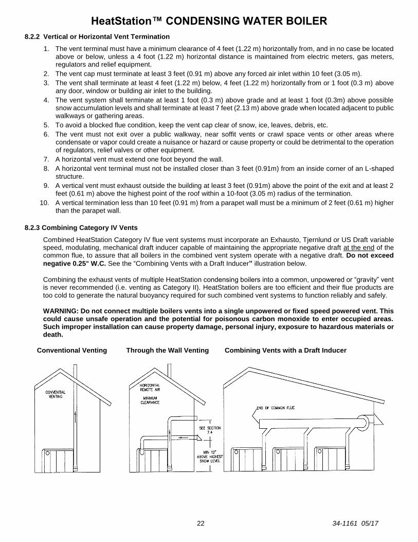
8.2.3 Combining Category IV Vents
Combined HeatStation Category IV flue vent systems must incorporate an Exhausto, Tjernlund or US Draft variable speed, modulating, mechanical draft inducer capable of maintaining the appropriate negative draft at the end of the common flue, to assure that all boilers in the combined vent system operate with a negative draft. Do not exceed
negative 0.25" W.C. See the “Combining Vents with a Draft Inducer” illustration below.
Combining the exhaust vents of multiple HeatStation condensing boilers into a common, unpowered or “gravity” vent is never recommended (i.e. venting as Category II). HeatStation boilers are too efficient and their flue products are too cold to generate the natural buoyancy required for such combined vent systems to function reliably and safely.
WARNING: Do not connect multiple boilers vents into a single unpowered or fixed speed powered vent. This could cause unsafe operation and the potential for poisonous carbon monoxide to enter occupied areas. Such improper installation can cause property damage, personal injury, exposure to hazardous materials or death.
Conventional Venting Through the Wall Venting Combining Vents with a Draft Inducer

HeatStation™ CONDENSING WATER BOILER
23 34-1161 05/17
8.2.4 Connecting to an Existing Vent System
Do not connect the HeatStation to an existing vent system, until it has been confirmed the existing vent system complies with all requirements for a new vent system. A venting system in full compliance with the instructions provided in this manual is required for safe and reliable operation of the HeatStation. Do not connect the HeatStation
to a masonry chimney.
WARNING: Before operating the appliance connected to an existing vent system, confirm the vent system complies with all guidance and requirements for a new vent system specified in this manual. Failure to confirm the existing vent system complies can result in unsafe operation and the potential for poisonous carbon monoxide to enter occupied areas and can cause property damage, personal injury, exposure to hazardous materials or death.
8.3 PVC Vent Installation
Follow the instructions below for installing schedule 40 solid PVC venting.
The stainless steel vent connection located near the rear of the boiler is 8" I.D with an internal gasket and clamp. This
connection will accept most 8 inch stainless or polypropylene venting. The HeatStation is also provided with an
adapter which will reduce the connection to 6 5/8" in order to directly couple to a PVC or CPVC vent system. (See
Section 8.2.1 Maximum Vent Length (Equivalent Lengths).
1. Read and follow the information, instructions and warnings in “VENTING” Section.
2. Do not insulate the plastic vent pipe.
3. Design the vent pipe route so that normal expansion (pipe getting longer) and contraction (pipe getting shorter), due to on and off temperatures, does not bind or put stress on cemented pipe fittings.
4. An adapter, increasing or reducing fitting must always be the first venting material attached to the HeatStation, when using PVC venting.
5. The adapter must be acceptable for the return temperatures up to 140°F and provide a sound air and water tight
seal.
6. Clean and deburr all solid PVC pipe ends, then trial assemble the entire vent system vent before joining with cement. Mark the pipe and fittings to identify their locations, then disassemble. Reassemble the vent system using fresh PVC cement to connect the PVC pipe. If both solid PVC and solid CPVC pipe are used in the same vent system, all joints between the two types of pipe must be made with fresh cement suitable for both materials. Follow the cement manufacturer’s instructions for making sound air and water tight joints.
7. Vent support – The PVC vent system must be supported at intervals no greater than four feet, to prevent sagging, distortion and stress on pipe fittings. Vertical pipe must also be supported to avoid stress on all cemented pipe fittings and to prevent putting excessive weight on the appliance vent connection.
8. The vent pipe must be sealed at the point where it passes through a wall or roof, to prevent rain, insects or flue products from entering the living space or interior of the building.
9. For proper vent operation, terminate the vent to prevent wind, water, debris or animals from obstructing the vent.
This can be done by terminating the vent downward and attaching a ¼" mesh to the outlet. Testing for leaks –
Once the vent system is installed, it must be checked to confirm all joints in the vent system are air and water tight. After the vent is assembled, close the end of the vent with a taped plastic bag. With the gas supply turned off, energize the HeatStation combustion blower to apply air pressure to the vent system. Spray each joint and vent connection with commercially available leak detection liquid to confirm no air is escaping from any point. Repair any leaks and retest. After testing is complete, de-energize the combustion blower, wipe clean the leak detection liquid and REMOVE the temporary vent closure.
10. Do not use a barometric damper with the HeatStation venting system. Barometric dampers are designed for use with certain Category I negative pressure vent systems. The HeatStation Category IV vent system operates with positive vent pressure and will not operate safely with a barometric damper.
HeatStation™ CONDENSING WATER BOILER
24 34-1161 05/17
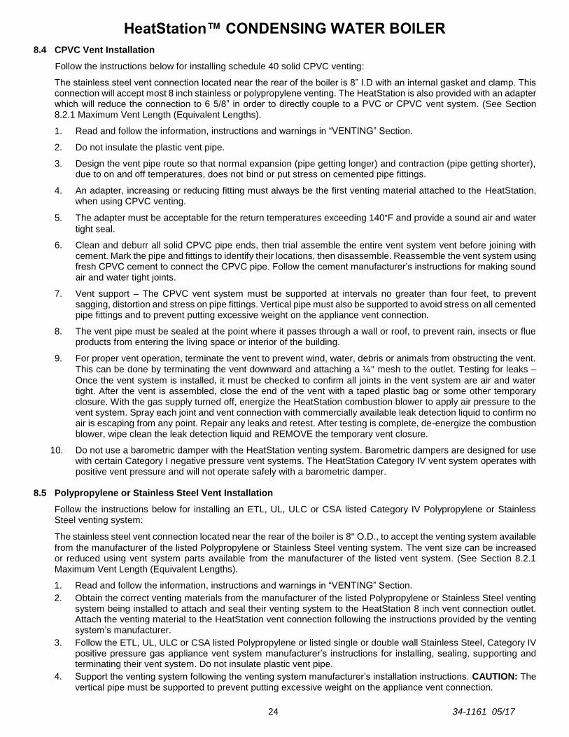
8.4 CPVC Vent Installation
Follow the instructions below for installing schedule 40 solid CPVC venting:
The stainless steel vent connection located near the rear of the boiler is 8” I.D with an internal gasket and clamp. This connection will accept most 8 inch stainless or polypropylene venting. The HeatStation is also provided with an adapter which will reduce the connection to 6 5/8” in order to directly couple to a PVC or CPVC vent system. (See Section 8.2.1 Maximum Vent Length (Equivalent Lengths).
1. Read and follow the information, instructions and warnings in “VENTING” Section.
2. Do not insulate the plastic vent pipe.
3. Design the vent pipe route so that normal expansion (pipe getting longer) and contraction (pipe getting shorter), due to on and off temperatures, does not bind or put stress on cemented pipe fittings.
4. An adapter, increasing or reducing fitting must always be the first venting material attached to the HeatStation, when using CPVC venting.
5. The adapter must be acceptable for the return temperatures exceeding 140°F and provide a sound air and water
tight seal.
6. Clean and deburr all solid CPVC pipe ends, then trial assemble the entire vent system vent before joining with cement. Mark the pipe and fittings to identify their locations, then disassemble. Reassemble the vent system using fresh CPVC cement to connect the CPVC pipe. Follow the cement manufacturer’s instructions for making sound air and water tight joints.
7. Vent support – The CPVC vent system must be supported at intervals no greater than four feet, to prevent sagging, distortion and stress on pipe fittings. Vertical pipe must also be supported to avoid stress on all cemented pipe fittings and to prevent putting excessive weight on the appliance vent connection.
8. The vent pipe must be sealed at the point where it passes through a wall or roof, to prevent rain, insects or flue products from entering the living space or interior of the building.
9. For proper vent operation, terminate the vent to prevent wind, water, debris or animals from obstructing the vent.
This can be done by terminating the vent downward and attaching a ¼" mesh to the outlet. Testing for leaks –
Once the vent system is installed, it must be checked to confirm all joints in the vent system are air and water tight. After the vent is assembled, close the end of the vent with a taped plastic bag or some other temporary closure. With the gas supply turned off, energize the HeatStation combustion blower to apply air pressure to the vent system. Spray each joint and vent connection with commercially available leak detection liquid to confirm no air is escaping from any point. Repair any leaks and retest. After testing is complete, de-energize the combustion blower, wipe clean the leak detection liquid and REMOVE the temporary vent closure.
10. Do not use a barometric damper with the HeatStation venting system. Barometric dampers are designed for use with certain Category I negative pressure vent systems. The HeatStation Category IV vent system operates with positive vent pressure and will not operate safely with a barometric damper.
8.5 Polypropylene or Stainless Steel Vent Installation
Follow the instructions below for installing an ETL, UL, ULC or CSA listed Category IV Polypropylene or Stainless Steel venting system:
The stainless steel vent connection located near the rear of the boiler is 8" O.D., to accept the venting system available
from the manufacturer of the listed Polypropylene or Stainless Steel venting system. The vent size can be increased or reduced using vent system parts available from the manufacturer of the listed vent system. (See Section 8.2.1 Maximum Vent Length (Equivalent Lengths).
1. Read and follow the information, instructions and warnings in “VENTING” Section.
2. Obtain the correct venting materials from the manufacturer of the listed Polypropylene or Stainless Steel venting system being installed to attach and seal their venting system to the HeatStation 8 inch vent connection outlet. Attach the venting material to the HeatStation vent connection following the instructions provided by the venting system’s manufacturer.
3. Follow the ETL, UL, ULC or CSA listed Polypropylene or listed single or double wall Stainless Steel, Category IV positive pressure gas appliance vent system manufacturer’s instructions for installing, sealing, supporting and terminating their vent system. Do not insulate plastic vent pipe.
4. Support the venting system following the venting system manufacturer’s installation instructions. CAUTION: The vertical pipe must be supported to prevent putting excessive weight on the appliance vent connection.
HeatStation™ CONDENSING WATER BOILER
25 34-1161 05/17
5. Seal the vent pipe at the point where it passes through a wall or roof following the venting system manufacturer’s installation instructions.
6. For proper vent operation, attach the vent system’s termination following the listed venting system manufacturer’s installation instructions.
7. Test the completed venting system for leaks following the venting system manufacturer’s installation instructions.
8. Do not use a barometric damper with the HeatStation venting system. Barometric dampers are designed for use with certain Category I negative pressure vent systems. The HeatStation Category IV vent system operates with positive vent pressure and will not operate safely with a barometric damper.
9 OPERATING AND SAFETY CONTROLS
9.1 Pressure Relief Valve(s)
A Pressure Relief Valve(s) sized in accordance with the ASME Boiler and Pressure Vessel Code, Section IV is installed in the boiler. WARNING: Secure the relief valve discharge pipe to a suitable floor drain such that very hot water does not openly splash during a significant relief valve discharge. If the relief valve discharge pipe is not routed and secured to a suitable drain, hot water discharge can result in property damage, scalding and personal injury or death. WARNING: Do not plug the relief valve(s), use discharge piping smaller than the relief valve opening or install a reducing coupling, valve or other restriction in the relief valve discharge line. Failure to comply with these relief valves and discharge piping requirements can prevent the relief valve from providing its intended pressure protection, which can result in a sudden loss of pressure containment that can cause property damage, exposure to hazardous materials, personal injury or death.
Follow the relief valve manufacturer’s installation and operating instructions and all local regional and national codes applicable to relief valve installation and discharge piping.
The relief valve discharge pipe must not be smaller than the relief valve opening and must be secured to prevent it from lifting out of the drain under discharge pressure and must be routed to allow complete drainage of the valve and piping.
Do not plug the relief valve(s) or install a reducing coupling, valve or other restriction in the relief valve discharge line(s), as this will eliminate the critical water pressure protection it provides.
Thermal Expansion - A relief valve that periodically discharges may result from thermal expansion. To control these periodic discharges, the boiler system must be provided with means to control expansion. Contact a boiler professional to resolve this situation.
9.2 Flow Switch
The boiler requires a minimum flow of 30 GPM to operate. When flow is sufficient, the Flow Switch will close allowing the operating control to energize. When flow is not sufficient, the Flow Switch will open, de-energizing the operating control and interrupting a firing cycle or call for heat. The Flow Switch is located in the return (lower) header connection pipe. The flow switch functions within the remote interlock safety circuit (see the Controls Section).
9.3 Blocked Flue Switch
A blockage in the venting or in the condensate trap will restrict the blower and increase pressure in the flue. A blockage in the condensate trap will block the flue by causing condensate to fill the the flue collector and restrict the discharge of flue gases. The Blocked Flue pressure switch (located in the control enclosure with tubing connected to the top of the flue plenum) senses this pressure. The PIM monitors the Blocked Flue Switch. If the pressure becomes too high (indicating a blocked condition), the PIM will not begin a call for heat.
9.4 Electronic Low Water Cut-Off
When the water level is above the electrode position in the boiler, the reset pushbutton will energize the control (LED will be lit). The control remains energized until the water level drops below the electrode position (LED will not be lit). Unless otherwise specified, there is a three-second time delay on decreasing level. Water level must be below the probe location for full three seconds before control de-energizes. The Electronic Low Water Cut-Off is located in the supply header.
IMPORTANT: Probe Sensitivity = 26K ohms (most water/glycol mixtures up to 50% concentration may be used).
HeatStation™ CONDENSING WATER BOILER
26 34-1161 05/17
WARNING: Turn off all electrical service to the appliance when accessing the limit or other controls located inside the control cabinet or inside the burner vestibule inside the top of the appliance. Close and fasten the control cabinet and burner vestibule cover before restoring electrical service to the appliance. The cabinet and burner vestibule contain High Voltage wiring and terminals. If the electrical service is not turned off and these terminals are touched, a dangerous shock causing property damage, personal injury or death could occur.
9.5 Operating Temperature Control
The water temperature is adjustable through a Touch Screen User Interface located in the front control panel. The control is factory pre-set at approximately 140ºF. Boiler Control Panel, Section 10.1, in this manual for more information. Suivez les instructions dans le manuel d'installation pour modifier la température de l'eau de la chaudière.
9.6 High Water Temperature Limit
The boiler Electronic Operating Control System (EOS) includes a single probe that contains a high water temperature limit and a completely separate supply water operating sensor. Since both these sensors are in the same location in the heated water supply, the EOS checks to be sure their output is within a degree or two of each other. If not, or if the maximum water temperature exceeds 210ºF, the EOS will lockout and the manual reset button on the control panel must be pressed before the boiler will resume operation.
HeatStation™ CONDENSING WATER BOILER
27 34-1161 05/17
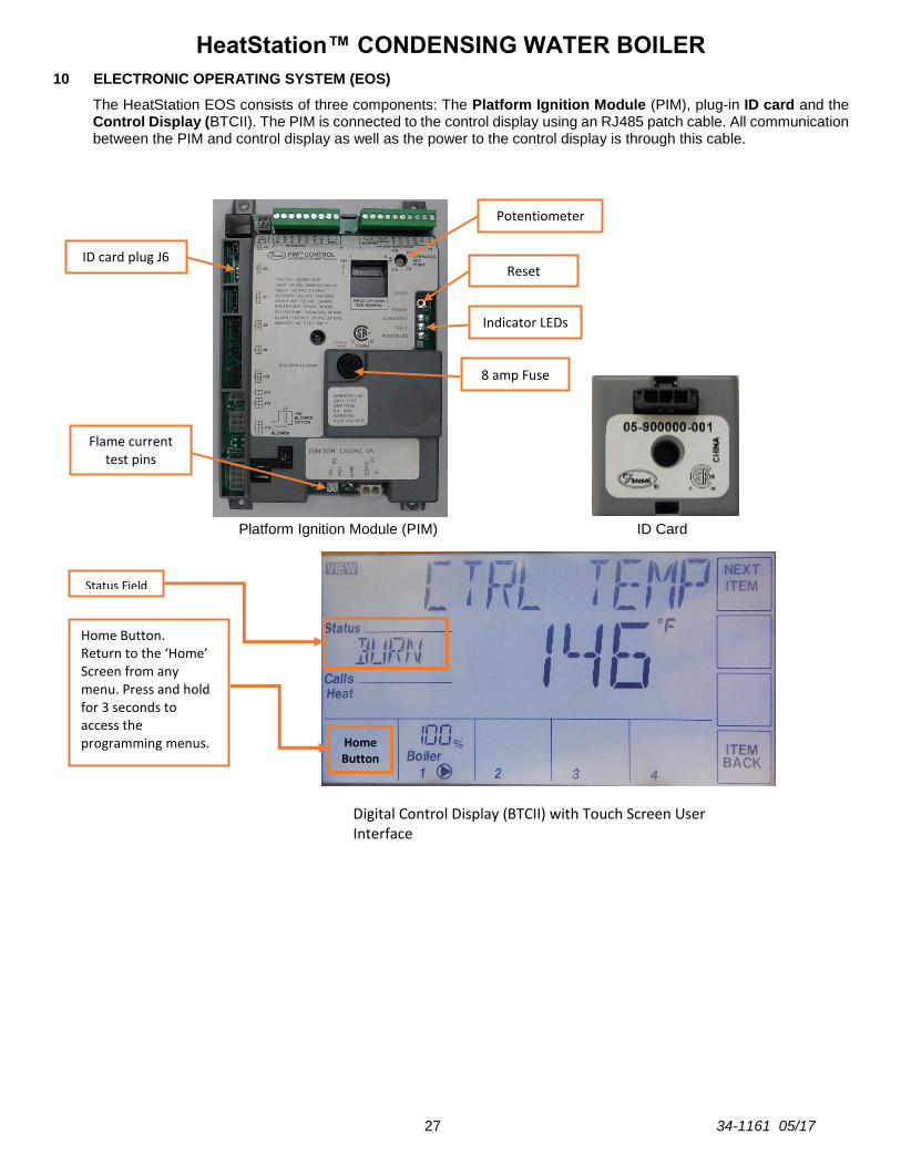
10 ELECTRONIC OPERATING SYSTEM (EOS)
The HeatStation EOS consists of three components: The Platform Ignition Module (PIM), plug-in ID card and the Control Display (BTCII). The PIM is connected to the control display using an RJ485 patch cable. All communication between the PIM and control display as well as the power to the control display is through this cable.
Platform Ignition Module (PIM) ID Card
Flame current test pins
ID card plug J6 Reset
Potentiometer
8 amp Fuse
Indicator LEDs
Home Button
Home Button. Return to the ‘Home’ Screen from any menu. Press and hold for 3 seconds to access the programming menus.
Digital Control Display (BTCII) with Touch Screen User Interface
Status Field

HeatStation™ CONDENSING WATER BOILER
28 34-1161 05/17
10.1 Touch Screen User Interface
The touchscreen of the EOS provides one-touch access to view and adjust various Menu set points. The touchscreen displays Status Fields, Items, Boiler Output and Number Fields. It also contains buttons for navigation & adjustment, and the Home Button to access menu selections.
10.2 Status Field Display
The Status Field displays the current operating status of the control display. Most items in the status field are only visible when in the View Menu or an alarm condition is present.
Item Description
HAND Hand Mode has been activated in the Manual Override Menu. This function allows the user to manually control the operation and firing rate of the burner.
OFF The Off mode indicates that the system has been disabled in the Manual Override Menu.
PURG When BLOWER is displayed in the main screen, PURG will indicate Post-Purge. The Purge mode also indicates that individual pumps have been activated in the Manual Override Menu.
IDLE The EOS is Idle due to no demand for heat
ARSW The EOS is attempting to purge but waiting for the air proving switch to prove blower air flow
PREP The EOS is Pre-Purging the burner system
IGN The Hot Surface Igniter is hot and the gas valve has opened to attempt burner ignition (4 seconds)
BURN The Burner has ignited and the flame has been sensed.
WWSD The boiler is currently in Warm Weather Shut Down mode. The boiler will still respond to calls for heat for DHW or pool heating.
10.3 Operational Sequence Field Display
The EOS displays the following burner operational sequence, ignition status, timings, temperatures and values:
Item Value
Displayed Description
SATISFIED ⁰F No Call For Heat based on temperature sensed at controlling sensor, usually in the supply piping. The controlling sensor the default display temperature.
STANDBY h:mm No Call For Heat based on inputs TH J1-9 (R1&R2) or DHW J1-8
CALL FOR HEAT Initiated when the temperature sensed at the control sensor in the supply piping is 10 degrees less than the setpoint temperature.
BLOWER mm:ss (PREP) Displays the Pre-Purge time from start of blower Pre-Purge, through heatup of igniter, and ends at start of trial for ignition.
BLOWER mm:ss (PURG) When the call for heat has ended, the post purge time countdown is displayed.
IGNITION mm:ss Displays trial for ignition, while the gas valves are bing energized, until fram signal is seen.
CURRENT 0 - 10 µA Flame sense signal shown as Flame Current (µA)
CTRL TEMP ⁰F Flame is established and the temperature sensed at the controlling sensor, usually in the supply piping is displayed.
HeatStation™ CONDENSING WATER BOILER
29 34-1161 05/17
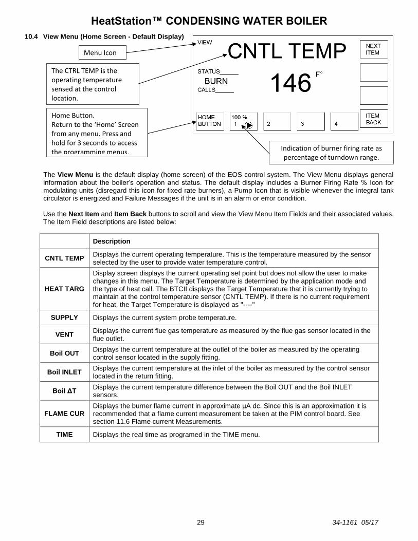
10.4 View Menu (Home Screen - Default Display)
The View Menu is the default display (home screen) of the EOS control system. The View Menu displays general information about the boiler’s operation and status. The default display includes a Burner Firing Rate % Icon for modulating units (disregard this icon for fixed rate burners), a Pump Icon that is visible whenever the integral tank circulator is energized and Failure Messages if the unit is in an alarm or error condition. Use the Next Item and Item Back buttons to scroll and view the View Menu Item Fields and their associated values. The Item Field descriptions are listed below:
Description
CNTL TEMP Displays the current operating temperature. This is the temperature measured by the sensor selected by the user to provide water temperature control.
HEAT TARG
Display screen displays the current operating set point but does not allow the user to make changes in this menu. The Target Temperature is determined by the application mode and the type of heat call. The BTCII displays the Target Temperature that it is currently trying to maintain at the control temperature sensor (CNTL TEMP). If there is no current requirement for heat, the Target Temperature is displayed as "----"
SUPPLY Displays the current system probe temperature.
VENT Displays the current flue gas temperature as measured by the flue gas sensor located in the flue outlet.
Boil OUT Displays the current temperature at the outlet of the boiler as measured by the operating control sensor located in the supply fitting.
Boil INLET Displays the current temperature at the inlet of the boiler as measured by the control sensor located in the return fitting.
Boil ΔT Displays the current temperature difference between the Boil OUT and the Boil INLET sensors.
FLAME CUR Displays the burner flame current in approximate µA dc. Since this is an approximation it is recommended that a flame current measurement be taken at the PIM control board. See section 11.6 Flame current Measurements.
TIME Displays the real time as programed in the TIME menu.
Indication of burner firing rate as percentage of turndown range.
Home Button. Return to the ‘Home’ Screen from any menu. Press and hold for 3 seconds to access the programming menus.
Menu Icon
The CTRL TEMP is the operating temperature sensed at the control location.

HeatStation™ CONDENSING WATER BOILER
30 34-1161 05/17
10.5 Control System Menus
The control display has multiple access levels. System critical settings will not be available for adjustment. The settings which can be adjusted by the user will display UP and DOWN adjustment arrows on the right side of the display screen. These programmable menu items are located in the Control System Menus. To access the Control System Menus:
1. Press and hold the Home button for 3 seconds.
2. Touch Next Item to navigate to the next menu. Touch Item Back to reverse.
3. Touch Enter to enter and change user accessible menu item settings in the control system menus.
4. Most setting are in the USER access level. Other setting will be located in the INSTaller or ADVanced access level depending on the necessity for field adjustment. See Using the Tool Box Menu for details.
Control System Menu Descriptions
10.6 Selecting the Correct Application Mode (INSTaller Level Access)
The EOS has five installer selectable application modes. The default application mode is SETP, this is an abbreviation for setpoint. When SETP is selected, The Heatstation will operate based on a fixed setpoint or (Operating Target). In this mode the operating sensor can be chosen but the Operating Target will not change independent of manual adjustment. See Section 10.8 and 10.9 for more details concerning sensor selection and adjusting the Operating Target.
The RESET mode will monitor the outdoor temperature and automatically adjust the Target setpoint up and down in order to provide the optimum system temperature based on changes in the outdoor temperature. See Section 10.13 for details.
The EMS mode will allow the user to directly control either the Target temperature or Direct Drive of the boiler/burner through the use of an external analog signal. See Section 10.16 for details.
The DDHW and POOL modes of operation are not currently supported by the EOS control system.
The following parameter is located in the SETUP MENU.
Menu Description
SETUP Displays and modifies the temperature control set points for the burner, changes to the operation type, and settings for operating modes.
SOURCE Displays many factory programmed settings for this product. The settings which can be adjusted by the user will be indicated by the appearance of the up and down adjustment arrows
MONITOR Displays operational information such as water and vent temperatures, hours of operation, and number of cycles
TIME Sets the time, day and year. Setting the time clock is necessary when using the scheduled setback
SCHEDULE Allows the user to create a schedule for reducing the boiler set point when a building is unoccupied for a period of time
NETWORK Displays and modifies parameters for creating a Modbus communication connection with the boiler
OVERRIDE Allows the user to assume manual control of the burner operation and pumps
TOOLBOX Displays alarm message history. Changes User access level and reset to factory default settings
Parameter Range Description
APP RESET, SETP,
EMS,DDHW, POOL The default application mode is SETP.

HeatStation™ CONDENSING WATER BOILER
31 34-1161 05/17
10.7 Control Setting for Hydronic System Design (USER Level Access)
There are some basic settings which must be made before commissioning this boiler. These setting will allow the boiler to function within different types of hydronic systems. Section 4 provides illustrations and details the application of the Single Boiler Primary only, Multi Boiler Primary only with Isolation Valve and Primary/Secondary hydronics systems.
The configuration of your system is made using the PIPING parameter in the SETUP MENU.
Parameter Range Description
PIPING P/S, PAR, VALV
The default setting will be P/S (Primary/Secondary). PAR stands for Single Boiler Primary only. VALV will activate the primary isolation valve output for a Multi Boiler Primary only system.
When the Primary/Secondary or Multi Boiler Primary Only system is chosen, the system sensor will be activated. This sensor must be installed by the installer, in the well provided. See the piping illustration in Section 4 for location. Control of an Isolation Valves for Multi Boiler Primary only systems or Primary Pumps for Primary/Secondary systems can be selected in Section 10.17 PIM DIP Switch Selectable Options and 13.4 Connecting Isolation Valves. It is recommended that Isolation valves should be configured for normally open, power close operation.
10.8 Selecting the Supply or Return Sensor for Single Boiler Primary Only Control
A four switch Dip panel is located on the back of the EOS HMI. CAUTION: Disconnect the power before accessing the internal control wiring to avoid serious injury.
10.9 Changing the Operating Target (USER Level Access)
The HeatStation BOILER operates to satisfy the appropriate operating temperature target of the EOS control. The value of the controls’ target is the desired operating target water temperature. The unit ships with a factory set point of 140°F.
Although the target can be displayed in the VIEW menu, it is necessary to enter the CONTROL SYSTEM MENU in order to make adjustments to the boiler target set point and other operational parameters. To Change the Boiler Target
1. From the View Menu, press and hold the Home button for 3 seconds.
2. Touch Next Item or Item Back buttons to navigate to the SETUP menu.
3. Touch the Enter button to display the SETUP menu.
4. Adjust the target value using the UP and DOWN arrow buttons. The new value will be saved when the screen is advanced to the next menu using the NEXT ITEM or BACK ITEM buttons or when exiting the menu by pressing the HOME button.
Dip switch 2 is factory set OFF which corresponds to Boiler Supply control (Outlet) Turning switch 2 ON will change the control sensor location to the Boiler Return (Inlet)

HeatStation™ CONDENSING WATER BOILER
32 34-1161 05/17
10.10 Setting the Real Time Clock (User & Installer Level Access)
The TIME MENU allows the user to program the time of day, the date and the year. A 12 or 24 hour time clock as well as daylight saving time can be selected. When selected, the time clock can be displayed in the VIEW MENU.
1. Press and hold the Home button for 3 seconds to enter the Control System Menu. Use the NEXT ITEM button to scroll to the TIME menu. Press the ENTER button to enter the TIME menu.
2. Use the NEXT ITEM button to move to the first screen. Use the UP & DOWN arrow buttons to set the hour, then press the NEXT ITEM button to enter the value and move to the minute. Once the parameters for the time screen have been entered, move to the date and year screen and enter settings in the same manner.
3. Continue using NEXT ITEM and arrows to adjust the remaining options; Dayling Savings (DST ON/OFF), display format (MODE 12hr/24hr), and clock is available in VIEW menu (CLOCK ON/OFF).
10.11 Scheduled Setback (USER Level Access)
The SCHEDULE MENU allows the user to program this boiler to automatically lower the operating set point for times when a facility is not occupied.
1. Enter the SCHEDULE MENU. Activate the schedule function by first turning on the HEAT SCHD using the arrow buttons.
2. There are four setback schedule types. 24hr, 5-2, 5-11 and 7DAY. The 24hr schedule is a daily schedule that will follow the same program every day of the week. The default schedule on the SCHD TYPE screen is the 24hr. All other schedule types are selected using the arrow buttons. The 24hr schedule allows for a 2 or a 4 EVENT/DAY. With the 2 event day, the user can have one occupied time and one unoccupied time per day. The 4 event day will allow for two occupied times and two unoccupied times per day.
NOTE: The unoccupied set points are programed in the SETUP MENU in the same manner that the occupied set point is adjusted.
For example, a 24hr type and a 4 event day schedule might look like this:
The 1st occupied time begins at 6:00am and the 1st unoccupied time begins at 11:00am, therefore, between the hours of 6:00am and 11:00am the occupied set point will be used.
The 2nd occupied period begins at 4:00pm and the 2nd unoccupied time begins at 10:00pm.
Between the 1st unoccupied time of 11:00am and the beginning of the 2nd occupied period, the unoccupied set point will be used.
At 4:00pm the 2nd occupied period will begin and the occupied set point will be used until the 2nd unoccupied period begins at 10:00pm.
From 10pm until 6:00am, the unoccupied set point will then be used.
Notice that schedule times and set points are identified as occupied (Occ) or unoccupied (UnOcc) here.

HeatStation™ CONDENSING WATER BOILER
33 34-1161 05/17
3. The 5-2 schedule type gives the user the ability to program a 2 or 4 EVENT/DAY but will also allow for one schedule to be followed Monday – Friday and then another Saturday and Sunday.
4. The 5-11 schedule type gives the user the ability to program a 2 or 4 EVENT/DAY but will also allow for one schedule to be followed Monday – Friday and then separate schedule Saturday and another Sunday.
5. The 7DAY schedule type gives the user the ability to program a 2 or 4 EVENT/DAY for each day of the week, Monday through Sunday.
10.12 Using the Manual Override Menu (INSTaller Level Access)
The OVERRIDE MENU is helpful during the initial commissioning as well as anytime burner adjustment is necessary. Manual override controls for the integral tank circulator and the optional SANI pump.
1. Enter the OVERRIDE MENU. Using the arrow buttons, select between the three choices. The default setting is AUTO. In the AUTO position the operating temperature control will work to control the water temperature based on the active set point. When manual control of boiler operation is complete, always return this parameter to the AUTO setting.
2. The second setting is OFF. This setting will stop all control function and prevent the burner from operating.
3. The third setting is HAND. Once enabled, use the NEXT ITEM button to scroll to the next screen. The TIMEOUT setting is a safety precaution that will disable the override function at the end of the specified time period if the MAN OVR setting is not returned to AUTO.
4. The next screen is SAN PUMP. To force on the SANI pump, turn this setting to ON.
5. The next screen is HTR PUMP. To force on the integral tank circulator, turn this setting to ON.
6. The next screen is HTR MOD. This setting will override the operating control and using the up and down arrow buttons, force the burner to fire at the selected firing rate. This function is useful when tuning the operation of the burner at a range of firing rates.
NOTE: If the HTR MOD control is activated while the burner is firing, the burner will shut down and recycle.
WARNING: When adjustments are complete and before putting the boiler into service, return the MAN OVR function back to “AUTO” Failure to return the MAN OVR function to “AUTO” can cause high water temperatures that can result in property damage, scalding, other serious injury or death.

HeatStation™ CONDENSING WATER BOILER
34 34-1161 05/17
10.13 10.13 Potentiometer (Operating Set Point for Standalone Operation)
The PIM ignition control will continue to operate the HeatStation to an internal setpoint (default is 140°F) should the touch screen control fail or communication between the two devices is interrupted. The internal set point can be adjusted using the potentiometer. This mode is intended as a temporary mode offering simplified heating for emergency heating situations. The controlling sensor will be the boiler supply sensor.
IMPORTANT: It is recommended that at the time of commissioning, the startup technician adjusts the potentiometer to the desired set point displayed in the OPERATOR screen located in the SOURCE control system menu. Do not use the index printed on the PIM. Only use the OPERATOR displayed Value for adjusting. (See Potentiometer Adjusting the setpoint Section 14.7)
10.14 Outdoor Reset Operation (INSTaller level access)
The Outdoor Reset function can be used to automatically adjust the Target setpoint up and down in order to provide the optimum system temperature based on changes in the outdoor temperature. Lowering the system temperature when then the outdoor temperatures are warmer can improve the efficiency of the boiler as well as the system heat exchangers. Raising the system temperature during the coldest weather can reduce up front system costs as well as improve the space heating comfort level. When Outdoor Reset operation is desired, there are additional control settings that need to be made in order for this function to be enabled.
The following parameters are located in the SETUP MENU:
Parameter Range Description
APP RESET, SETP,
EMS,DDHW, POOL The default application mode is SETP, to enable Outdoor Reset, change this parameter setting to RESET.
OUT DSGN -60 to 45°F This is the outdoor system design temperature for the installation.
OUT START 35 to 100°F This is the outdoor temperature that would require any heating.
Boil START BOil MIN to 150°F This is a theoretical temperature that would be required
Boil DSGN 70 to BOil MAX This is the system temperature required to meet the heating load at the outdoor system design temperature.
WWSD 35 TO 100°F
Warm Weather Shut Down is an outdoor temperature at which natural heating of the building will meet the heating needs. This will not affect operation from a DHW call for heat. If you wish for the boiler to continue when the outdoor temperature is above the OUT START temperature, set this to OFF.
BOil MIN OFF, 60F to 180F Boiler Minimum calculated set point (HEAT TARGET). Caps the lowest set point to operate the boiler. If OFF, calculated setpoint can go below expected values.
BOil MAX OFF, 200F to 70F Boiler Maximum calculated set point (HEAT TARGET). Caps the highest set point to operate the boiler. If OFF, calculated set point can go higher than expected values.

HeatStation™ CONDENSING WATER BOILER
35 34-1161 05/17
The target temperature will be adjusted based on an internally calculated reset ratio. The calculations are as follows:
The Outdoor Sensor (PVI part# 143612) should be wired to the PIM control terminal as illustrated below:
Connect Outdoor Sensor to the ORD and GND terminals. Use 18 AWG or similar wire between control and sensor. Do not run the wires parallel to telephone or power cables. If the wires are located in an area with strong sources of electromagnetic interference (EMI), shielded cable or twisted pair should be used. The Outdoor Sensor will share the GND terminal with the System Sensor.

HeatStation™ CONDENSING WATER BOILER
36 34-1161 05/17
10.15 Multiple Boiler Cascade System (INSTaller level access)
The Cascade function is intended to be used with any Multi Boiler installation. The EOS control system on HeatStation is capable of controlling 12 boilers in a cascade system. Cascading multiple boilers is important for a number of reasons.
NOTE: When the boiler is referred to as condensing or non-condensing, remember that all HeatStation boilers are condensing.
Cascading will match the building heat load by allowing the minimum number of boilers to operate in order to meet the heat demand.
Cascading will attempt to balance the run time of each member of the boiler group. This is important long term because it minimizes uneven wear on individual boiler and make it easier to estimate maintenance for the group.
Cascading can increase system efficiency by operating condensing boilers at the minimum firing rates longer.
Cascading can reduce component wear as well by operating fewer boilers at their maximum output.
1. Parallel Modulation Cascade can optimize system efficiency by operating condensing boilers at the minimum firing rate and bringing additional boilers on when the enabled boilers reach the programmed burner modulation rate. The MOD COND % is the parameter which selects that trigger modulation rate.The default value is 50% and is adjustable up to 100%. Each boiler in this system must be identified as condensing. The CONDENSE parameter located in the SOURSE menu should be selected to be ON.
Example: In a 4 boiler system with the MOD COM parameter set at 75%, when the Master boiler reaches 75% burner modulation rate, the EOS will enable boiler #2 and reduce the modulation rate to a minimum. As the heat load increases, the EOS will increase the firing rate of both boilers in parallel until they both reach 75%. EOS will then enable boiler #3 and so on.
2. Sequential Modulation Cascade will reduce component wear as well as electrical consumption by maximizing the heat output of one boiler before bringing on additional boilers. When the MOD COND parameter is set to 100% the cascade function automatically becomes Sequential Modulation.
Example: In a 4 boiler system with the MOD COND parameter set at 100%, when the Master boiler reaches 100% burner modulation rate and the building load continues to rise, the EOS will enable boiler #2. As the load continues to rise, EOS will modulate the boiler #2 burner to a higher firing rate until this boiler also operates at 100% and so on.
Fundamental to creating a cascade boiler system, is establishing the identity of individual boilers and the communication between them. The ADDRESS parameter allows the user to assign a unique address for each boiler. Because any cascade system requires that a common sensor be used regulate the operation of all boilers in the system, the P/S (Primary/Secondary) hydronic system must be selected regardless of the type of piping system utilized for the installation. See Section 10.7 for details.
Establishing the electrical connection between boilers requires a two wire cable. It is recommended that 18 gauge, stranded copper wire within a shielded cable. A twisted pair cable is not required but may be advisable when communication wiring is run in a common conduit with high voltage, current carrying electrical service.

HeatStation™ CONDENSING WATER BOILER
37 34-1161 05/17
The following illustration shows how to establish a communication link between boilers:
The following parameters are used to set up your cascade operation. When boiler #1 is assigned the MSTR (Master) identifier, Cascading will automatically be activated.
Parameter Range Description
ADDRESS NONE, MSTR,
2,3,4…..,12
The ADDRESS parameter will assign a unique identifier to each boiler. Boiler #1 should be assigned MSTR (Master). The MSTR boiler will initiate the cascade control commands. Each consecutive boiler should be assigned a number.
PIPING P/S, PAR, VALV When setting up a Cascade system, always select the P/S (Primary/Secondary) piping regardless of the actual installed system.
CONDENSE OFF, ON This parameter should be preset to ON for the Heatstation but the correct state should be verified during setup.
MOD COND 50 to 100%
For Parallel modulation, this parameter will select the burner modulation percentage, once reached, will trigger the next boiler to be enabled. When adjusted to 100%, cascade function effectively becomes Sequential.
FIXED LEAD OFF, ON When all the boilers in the system are either condensing or non-condensing, this parameter, when enabled will select a fixed lead boiler.
ROT COND OFF, ON
This parameter turns on rotation for the condensing boiler group in a mixed system of condensing and non-condensing boilers. When enabled, the lead boiler will be rotated every 48 hours. Consult factory when designing such a system for additional guidance.
ROT NC OFF, ON This parameter turns on rotation for the non-condensing boiler group in a mixed system.
The tN4 and GND terminals are the communication point for the PIM.
Terminal tN4 and GND should be connected in a daisy chain manner to each between each boiler. Polarity mush be respected.

HeatStation™ CONDENSING WATER BOILER
38 34-1161 05/17
10.16 EMS Control (Energy Management System)
The EMS function will allow the user to directly control either the Target temperature or Direct Drive of the boiler/burner through the use of an external analog signal. This function can be configured to respond to 0-10, 2-10 Vdc or 4-20 mA. Utilize DIP switches 2, 5, 6.
Enabling this function requires adjustments to both the PIM(Platform Ignition Module) and the BTCII(HMI). See the following Section on PIM DIP Switch Options for details on PIM settings. The parameters in the table below are located on the BTCII.
Parameter Range Description
APP RESET, SETP,
EMS,DDHW, POOL
The default application mode is SETP, to enable energy management system control using an analog signal, change this parameter setting to EMS. DIP switch #5 must be on for EMS menu to be present.
SIGNAL 0-10Vdc, 2-10Vdc When DIP switch #6 selects 0-10Vdc this parameter can also allow for a truncated signal of 2-10Vdc.
SETP LO Boil MIN to SETP HI This setting will define the EMS Target when The EMS signal = 1.0Vdc(0-10Vdc) or 2.0Vdc when (2-10Vdc) is selected.
SETP HI SETP LO to Boil
MAX Defines the EMS Target when the EMS signal = 10.0 Vdc
If the EMS control method is Target temperature, consider the following example:
Example: 0-10Vdc is selected. The SETP LO is set to 100° and SETP HI is set to 180°F. When the 0-10Vdc signal rises from 0 to 1.0Vdc, the call for heat will be made and the Target temperature will be set at 100°F. When the signal reaches 10.0Vdc, the Target temperature will be 180°F. The Target temperature will vary linearly between 1-10Vdc.
If the EMS control method is Direct Drive of the boiler/burner, consider the following example:
Example: 2-10Vdc is selected. When the 2-10Vdc signal rises from 0 to 2.0Vdc, the call for heat will be made and the burner will operate at the firing rate defined by the MIN MOD setting located in the SOURCE MENU (~10%). When the signal reaches 10.0Vdc, the burner will operate at the firing rate defined by the MAX MOD setting located in the SOURCE MENU (~100). The burner will modulate linearly between 1-10Vdc. Do not attempt to adjust the MIN MOD or MAX MOD setting. Unsafe operation can occur.
When 4-20mA is applied, a 500Ω, 1/2W resistor is placed across the EMS terminals. The method of operation and adjustment are the same. At a 4mA signal, the PIM will see a 2VDC signal, at 20mA signal, the PIM will see a 10VDC signal.
10.17 PIM DIP Switch Selectable Options
There is an 8 DIP switch panel on the front of the PIM. Some options must be enabled by turning on the applicable DIP switch. All DIP switches are in the OFF position as supplied.
1. Switch #1 – The EOS uses a PID algorithm to regulate system temperature. The OFF position (default) of this switch selects Auto Differential. This allow the BTCII to regulate system temperature with optimum accuracy. The on position will in turn select Manual Differential. This state should only be selected when advised by the Riverside Hydronics application specialist.
2. Switch #2 – This switch selects the type of EMS control. The OFF position (default) will adjust Target Temperature when EMS is enabled. The ON position will allow for Direct Drive of the boiler/burner. See the EMS Section for more details.
Switch #3 – This switch selects control logic used for isolation valves or boiler pumps. When using an Isolation valve in a Primary only system, switch #3 should be left in the OFF position. In the OFF position the EOS will power the CIRCULATOR circuit when the heating cycle is over in order to close the valve. For a Primary/Secondary system, switch #3 should be in the ON position in order to power this circuit for operation of a pump during boiler operation.
ON = Sends signal to run a pump.
OFF = Sends signal to close isolation valve.
HeatStation™ CONDENSING WATER BOILER
39 34-1161 05/17
3. Switch #4 – Enables Pump Exercise. When enabled (ON position), the primary pump will cycle for 10 seconds every 72 hours, even with no heat demand, to help extend the life of the pumps.
4. Switch #5 – Enables the EMS function. See the Section on EMS Control.
5. Switch #6 – When EMS is enabled, this switch selects between 0-10Vdc (OFF position) and 4-20mA (ON position). Resistor must be installed when using 4-20mA. See Section EMS Control.
6. Switch #7 - Enables Freeze Protection. When enabled (ON position) if either the Supply sensor (Outlet) or the Return sensor (Inlet) temperature drops below 45°F, the boiler and system pumps shall be enabled. The pumps will be turned off when both the Supply and Return temperatures rise above 50°F. If either the Supply or Return temperature drops below 38°F, the burner shall start at the minimum firing rate. The heating cycle will end when both Supply and Return temperatures rise above 42°F.
7. Switch #8 – The Commission Test mode is only used when the PIM is in standalone mode (not used with BTCII). This function is not need with the EOS control system.
10.18 Using Tool Box Menu
The TOOL BOX MENU contains several adjustable parameters as well as up to the 15 past alarm messages logged.
1. The first screen in the Tool Box is for the ACCESS level. The three choices available here are USER, INSTaller and ADVanced. Consult factory before changing any settings requiring an ADVanced access level. Depending on the access level selected, different parameters will become visible and adjustable. Selecting the appropriate access level will make menu navigation easier and minimize the possibility that parameters will be unintentionally changed, resulting in improper operation.
2. The second screen will display the software revision for the touch panel display, the major revision is displayed. Press the enter button to view the minor revision number.
3. The third screen allows the user to turn the display backlight ON continuously, OFF or TMPY will keep the backlight on only during use.
4. The fourth screen allows the user to choose between Fahrenheit and Celsius.
5. All of the following screens will display the most recent alarm messages up to 15. The Status field will show messages beginning with the most recent. This screen will display the time and date of the failure. Time and date must be set for the events to reflect actual time and dates they took place.

HeatStation™ CONDENSING WATER BOILER
40 34-1161 05/17
11 COMMUNICATIONS AND DIAGNOSTICS
11.1 Indicators
The PIM has three LED indicators to display operational status and to help diagnose system error conditions:
Power: Green LED indicating the PIM module is receiving 24 VAC power.
Alarm/Test: Amber LED which indicates the PIM is in Commission Test Mode or that a diagnostic alarm (fault) is present.
Diagnostic Code: Red LED that is normally off. During a control or system fault condition, this LED flashes the error codes.
11.2 Alarm Messages – Diagnostic Codes (Flashes)
ALARM MESSAGE
DESCRIPTION OF ALARM LED
Flashes
MODBUS
CODE #
ID CARD
The ID card is connected to the PIM control board when the system is initialized for the first time, the ID card selects the control profile to be used. An ID card error may occur when the original card is replaced with an incorrect card or has been disconnected from the PIM control board.
Red LED ON, Green LED OFF
20
INTERNAL FAIL The PIM control board may have failed. Replace the control board if manually resetting the control does not correct the fault.
Red LED ON
21
CTL SETUP FAIL
Try resetting the defaults in the TOOL BOX menu. If unable to correct, replace the control display
N/A 1
VENT LIM The vent temperature sensor is approaching the programmed limit. This will force the burner to operate at a reduced firing rate to prevent overheating.
N/A 5
AIR FLOW FAIL Indicates a blockage in the vent or condensate trap. 1 9
FLAME FLSE
A false flame signal is usually cause by a leaky gas valve which propagates a flame after the call for heat cycle has ended. Check for leakage through the gas valve. If no mechanical cause can be found, replace flame control.
2 19
FLAME FAIL
Flame failure indicates that during the burner ignition process, the burner either failed to light or it did light but no flame signal was detected. If the burner fails to light it is likely that the hot surface igniter (HSI) is faulty or the burner fuel/air mixture is too far out of adjustment to ignite. If the burner lights but immediately go out, check for an inadequate gas supply, faulty gas valve or regulator or poorly adjusted combustion.
3 15
FLAME LOSS
Flame loss indicates that sometime after flame has been established and the burner is operating, the flame signal is lost. This can be caused by a faulty igniter, damaged refractory or combustion that becomes poorly adjusted as the burner modulates to higher inputs.
3 16
LOW HSI The PIM control board is not sensing the correct amp draw from the HSI (Hot Surface Igniter). This is most likely caused by a faulty or disconnected igniter.
4 23
LOW 24VAC The 24VAC supply to the PIM control is below the threshold for reliable control operation. This may be caused by low voltage to the boiler or a faulty 120/24VAC supply transformer.
5 24
VENT MAX
The vent temperature sensor is used to protect low temperature vent systems from damage caused by high flue gas temperatures. When this alarm occurs, first confirm that the vent material is suitable for the application as well as the limit setting for this control. When this product is operated with high return or inlet water temperature, the flue gas can exceed the rating of low temperature vent systems.
6 17
Boil MAX The boiler high limit temperature safety has exceeded its limit. This condition may be caused by a sensor failure or a faulty control board.
7 18
ALARM MESSAGE
DESCRIPTION OF ALARM LED
Flashes
MODBUS
CODE #
HeatStation™ CONDENSING WATER BOILER
41 34-1161 05/17
11.3 Replacing the Fuse
The 24 VAC input and output circuits of the PIM are protected by a 8.0 Amp fuse.
11.4 Self-Check / Control Failure
The PIM confirms the integrity of the gas valve relay contacts to insure safety. It also monitors the processor memory and software execution for proper program flow. If the control detects an error in its software or hardware, all outputs are turned off and the LED displays a steady ON condition. If this condition persists after an attempt to restart then the control must be replaced.
11.5 System Safety Checks
The PIM monitors the safety switches, temperature sensors, supply voltage, and blower speed and will go to soft lockout until the error condition is corrected. Individual LED diagnostic codes or messages on the RS485 communications help identify the problem for efficient troubleshooting.
11.6 Flame Current Measurements
The PIM supports direct measurement of flame signal strength using the flame current test pins (FC+, FC-) on connector P2. Flame current may be measured by a micro-ammeter, or alternately by using a standard digital voltmeter. The signal on P2 is calibrated to 1 micro-amp/volt, so flame current in micro-amps can be directly read on the volts scale.
The control display user interface is capable of displaying an approximation of flame current up to 5 micro-amps.
11.7 Non-Volatile Lockout / Manual Reset
The PIM normally allows for volatile ignition lockout where a lockout condition is reset by a loss in 24VAC power or the call for heat demand. In certain applications or where required by standards (such a CSD-1), it can be configured through the parameter settings for non-volatile lockout after ignition failure. In this case the lockout may only be reset by the on-board manual reset button, or the remote reset input.
11.8 ID Card
Boil OUT Indicates a problem with the supply temperature sensor, possibly a broken or shorted sensor wire or failed sensor. NOTE: The boiler supply sensor and the high limit sensor or located in the same probe body.
8 11
HI LIMIT Indicates a problem with the high limit temperature sensor, possibly a broken or shorted sensor wire or failed sensor. NOTE: The boiler supply sensor and the high limit sensor or located in the same probe body.
8 14
Boil INLET Indicates a problem with the boiler return temperature sensor, possibly a broken or shorted sensor wire or failed sensor.
8 12
VENT Indicates a problem with the vent temperature sensor, possibly a broken or shorted sensor wire or failed sensor.
8 13
LOGASPRES FAIL
The low gas pressure safety switch is not sensing the minimum gas pressure required for safe burner operation. Check the gas pressure to ensure that the minimum is available. If the gas pressure is adequate check for fluctuating gas pressure or a faulty pressure switch.
9 10
REM PROV FAIL
The remote proving circuit checks for proper operation of the water flow switch, as well as ancillary mechanical room equipment. Verify minimum water flow as well as proper wiring and function and flow switch and ancillary mechanical equipment. See Sec 12.2.
10 8
LOW WATER FAIL
The electronic low water cutoff is no longer sensing water at its probe. This could also be caused by a faulty low water board or sensor
12 7
HTR LOST This could be caused by a poor connection between the PIM control and the digital control display or failure of either device.
14 6
HIGASPRES Check the gas pressure to ensure that the building supply doesn’t exceed the value on the boiler rating plate. If the gas pressure is within rated limit, check for a faulty pressure switch.
15 26
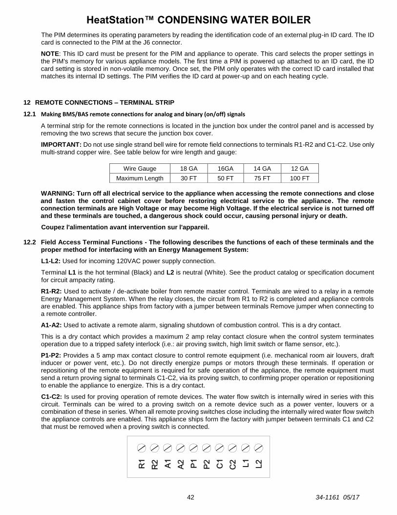
HeatStation™ CONDENSING WATER BOILER
42 34-1161 05/17
The PIM determines its operating parameters by reading the identification code of an external plug-in ID card. The ID card is connected to the PIM at the J6 connector.
NOTE: This ID card must be present for the PIM and appliance to operate. This card selects the proper settings in the PIM's memory for various appliance models. The first time a PIM is powered up attached to an ID card, the ID card setting is stored in non-volatile memory. Once set, the PIM only operates with the correct ID card installed that matches its internal ID settings. The PIM verifies the ID card at power-up and on each heating cycle.
12 REMOTE CONNECTIONS – TERMINAL STRIP
12.1 Making BMS/BAS remote connections for analog and binary (on/off) signals
A terminal strip for the remote connections is located in the junction box under the control panel and is accessed by removing the two screws that secure the junction box cover.
IMPORTANT: Do not use single strand bell wire for remote field connections to terminals R1-R2 and C1-C2. Use only multi-strand copper wire. See table below for wire length and gauge:
WARNING: Turn off all electrical service to the appliance when accessing the remote connections and close and fasten the control cabinet cover before restoring electrical service to the appliance. The remote connection terminals are High Voltage or may become High Voltage. If the electrical service is not turned off and these terminals are touched, a dangerous shock could occur, causing personal injury or death.
Coupez l'alimentation avant intervention sur l'appareil. 12.2 Field Access Terminal Functions - The following describes the functions of each of these terminals and the
proper method for interfacing with an Energy Management System:
L1-L2: Used for incoming 120VAC power supply connection.
Terminal L1 is the hot terminal (Black) and L2 is neutral (White). See the product catalog or specification document for circuit ampacity rating.
R1-R2: Used to activate / de-activate boiler from remote master control. Terminals are wired to a relay in a remote Energy Management System. When the relay closes, the circuit from R1 to R2 is completed and appliance controls are enabled. This appliance ships from factory with a jumper between terminals Remove jumper when connecting to a remote controller.
A1-A2: Used to activate a remote alarm, signaling shutdown of combustion control. This is a dry contact.
This is a dry contact which provides a maximum 2 amp relay contact closure when the control system terminates operation due to a tripped safety interlock (i.e.: air proving switch, high limit switch or flame sensor, etc.).
P1-P2: Provides a 5 amp max contact closure to control remote equipment (i.e. mechanical room air louvers, draft inducer or power vent, etc.). Do not directly energize pumps or motors through these terminals. If operation or repositioning of the remote equipment is required for safe operation of the appliance, the remote equipment must send a return proving signal to terminals C1-C2, via its proving switch, to confirming proper operation or repositioning to enable the appliance to energize. This is a dry contact.
C1-C2: Is used for proving operation of remote devices. The water flow switch is internally wired in series with this circuit. Terminals can be wired to a proving switch on a remote device such as a power venter, louvers or a combination of these in series. When all remote proving switches close including the internally wired water flow switch the appliance controls are enabled. This appliance ships form the factory with jumper between terminals C1 and C2 that must be removed when a proving switch is connected.
Wire Gauge 18 GA 16GA 14 GA 12 GA
Maximum Length 30 FT 50 FT 75 FT 100 FT
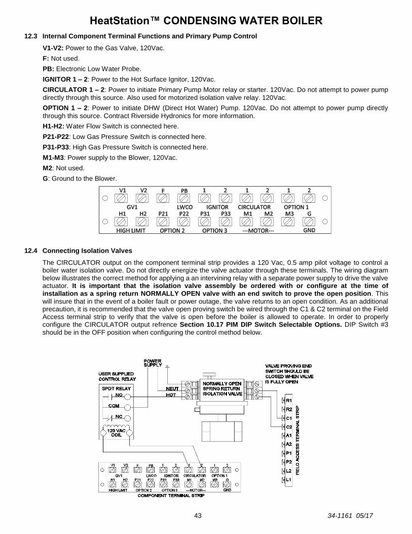
HeatStation™ CONDENSING WATER BOILER
43 34-1161 05/17
12.3 Internal Component Terminal Functions and Primary Pump Control
V1-V2: Power to the Gas Valve, 120Vac.
F: Not used.
PB: Electronic Low Water Probe.
IGNITOR 1 – 2: Power to the Hot Surface Ignitor, 120Vac.
CIRCULATOR 1 – 2: Power to initiate Primary Pump Motor relay or starter. 120Vac. Do not attempt to power pump
directly through this source. Also used for motorized isolation valve relay. 120Vac.
OPTION 1 – 2: Power to initiate DHW (Direct Hot Water) Pump. 120Vac. Do not attempt to power pump directly
through this source. Contract Riverside Hydronics for more information.
H1-H2: Water Flow Switch is connected here.
P21-P22: Low Gas Pressure Switch is connected here.
P31-P33: High Gas Pressure Switch is connected here.
M1-M3: Power supply to the Blower, 120Vac.
M2: Not used.
G: Ground to the Blower.
12.4 Connecting Isolation Valves
The CIRCULATOR output on the component terminal strip provides a 120 Vac, 0.5 amp pilot voltage to control a boiler water isolation valve. Do not directly energize the valve actuator through these terminals. The wiring diagram below illustrates the correct method for applying a an intervining relay with a separate power supply to drive the valve actuator. It is important that the isolation valve assembly be ordered with or configure at the time of installation as a spring return NORMALLY OPEN valve with an end switch to prove the open position. This will insure that in the event of a boiler fault or power outage, the valve returns to an open condition. As an additional precaution, it is recommended that the valve open proving switch be wired through the C1 & C2 terminal on the Field Access terminal strip to verify that the valve is open before the boiler is allowed to operate. In order to properly configure the CIRCULATOR output refrence Section 10.17 PIM DIP Switch Selectable Options. DIP Switch #3 should be in the OFF position when configuring the control method below.

HeatStation™ CONDENSING WATER BOILER
44 34-1161 05/17
13 SEQUENCE OF OPERATION
1. Incoming 120VAC
a. Full time power to the Main Control Switch.
2. Power On - When the main control switch is turned on power is applied to the fuse then:
a. 120V is applied to the step-down transformer (24V), L.W.C.O, J12-6, J14-3, J14-5, L1 terminals and the control switch lamp.
b. Both 24V and 120V is applied to the Platform Ignition Module (PIM). The circulator, blower and HSI circuits are 120V.
c. The PIM performs a processor and memory self-test to insure proper operation. The PIM confirms the presence of a valid ID card which matches the configuration previously stored in memory. If the valid ID card is not present, the PIM generates a diagnostic fault. The non-volatile memory is checked for an active lockout condition. A lockout indicates the previous attempt to light was unsuccessful, or a hi-limit or other system fault occurred. The PIM stays in lockout until a manual reset is performed.
d. The PIM powers the BTCII display.
3. Control Device Pre-check – The following control circuits are checked for closure before the control system will initiate a Call for Heat.
a. The PIM continuously monitors the flame status to verify no flame is present during Standby. If an erroneous flame is detected, the PIM generates a flame error fault.
b. The Electronic Low Water Cut-Off control is a self-contained electronic device which senses the presence of water at the boiler supply manifold. When the presence of water is confirmed, the contacts close on the ELWCO and is sensed by PIM control.
c. The High Temperature Limit is combined in a common probe body with the supply sensor, located in the upper header. The PIM compares the high limit temperature with the supply sensor temperature. If the two temperatures are not the same, a sensor failure will result.
d. When the High Temperature Limit operation has been verified by comparison, the limit temperature will then be confirmed to be under the maximum allowable temperature.
e. The Flow Switch is made up and continuously monitored to ensure sufficient water flow through the boiler. Insufficient flow will overheat the boiler. If flow is not sufficient, call for heat will be prevented or interrupted and an error will result. Flow switch is terminals H1 & H2. The Flow Switch is in line with the interlock remote proving terminals C1 & C2. H1 from the flow switch feeds C2.
4. Call For Heat - If the operating control senses that the temperature at the applicable operating sensor is below
the boiler set point by more than the differential and the previous control interlocks and safeties are satisfied, the following sequence will begin:
a. The High Gas Pressure and Low Gas Pressure Switch are proved.
b. When the blower is energized the PIM uses a feedback loop to confirm blower speed.
c. Terminals P1-P2 are closed to activate any connected remote devices.
d. The circuit between Terminals C1-C2 is closed by any connected remote proving switches, enabling the boiler to continue the sequence of operation.
e. After all proving all proving circuits and blower operation are verified, the BLOWER PRE-PURGE will starts counting.
f. During pre-purge the blocked flue switch senses that the vent and condensate trap are not blocked.
g. The ignition pre-purge delay takes place.
h. The voltage level of the 24 VAC supply input is confirmed to be above 18.0 VAC.
i. The Ignition cycle begins.
HeatStation™ CONDENSING WATER BOILER
45 34-1161 05/17
5. Heat-Up - Following the pre-purge delay, the hot surface igniter will be energized:
a. The flame control will send 120V to the hot surface igniter for approximately 20 seconds.
b. The HSI Element proving current is verified.
c. The heat-up delay takes place to allow the hot surface element to reach ignition temperature.
6. Ignition - When the 20 second heat-up time is completed a 4-second Trial for Ignition (TFI) period is initiated:
a. The Gas Safety Valves are energized.
b. The hot surface element is de-energized during the last second of the TFI period, to allow detection of flame.
c. The flame control will monitor the flame using flame rectification through the hot surface igniter.
d. If the flame control senses the presence of flame before the end of the TFI period, the flame control will continue to monitor the flame, through the igniter, until the call for heat condition ends.
7. Heating
a. The flame status, fan speed, LWCO switch, high/low gas switches, and other safety switches are continually monitored for proper state. The blocked flue is only monitored during pre-purge.
b. The High Limit sensor is confirmed to read below the High Limit setpoint.
c. The temperature of the controlling sensor is compared to the temperature control set point to determine when to begin firing in heating mode.
d. The boiler remains in heating mode and, with extended operation, condensation begins to fill the condensation trap and drain line. The boiler attempts to match the temperature control target by modulating the firing rate around the target temperature.
e. The gas valve(s) are immediately disabled.
f. A Blower Post-purge is completed and the control proceeds to Standby mode.
8. Flame Failure / Flame Loss
a. If the igniter fails to sense flame during an attempt to light the burner (Ignition Trail Fail), the ignition control will end the ignition sequence and the gas valve will be closed. Immediately following the end of the first failed ignition cycle, the HeatStation will enter a hard lockout state. The standard configuration of the HeatStation boiler allows for only one ignition failure before lockout and requires manual reset to meet CSD-1 requirements.
b. If the burner successfully lights and operates but the flame is lost, the gas valve will be closed and the blower will continue to operate in order to purge any remaining combustion products from the boiler. This flame loss will result in a lockout and requires manual reset to attempt operation again. The standard configuration of the HeatStation boiler allows for only one (Main Flame Loss) occurrence before lockout.
HeatStation™ CONDENSING WATER BOILER
46 34-1161 05/17
14 INITIAL STARTUP
14.1 Initial Startup Requirements
Installation must be complete prior to performing initial startup; and the startup must be complete prior to placing the boiler into service. Starting the boiler without proper piping, combustion air, venting or electrical connections or control settings can be dangerous and may void the product warranty. The following startup instructions must be followed precisely in order to achieve proper and efficient operation to assure trouble-free service life.
WARNING: Proper startup must be made by a qualified installer or service agency, who must read and follow the supplied instructions and appliance markings. Failure to complete proper startup before use, tampering with controls or not following all instructions and markings may damage this equipment, void the warranty and may result in property damage, personal injury or death.
14.2 Tools and Instrumentation Required
Stack Temperature Gauge.
Stack Draft Gauge.
Electronic Combustion Analyzer.
Two U-tube Manometers or pressure gauges.
AC/DC Multi-meter capable of reading low voltage, including less than a volt AC/DC, OHM, and line voltage.
Amp Meter (0.0 – 10.0 Amp)
Normal Hand Tools.
14.3 Resources
Product Installation & Maintenance Manuals.
Start-up Report with instructions.
Local, State, & Federal Codes.
Website: www.riversidehydronics.com
Technical Support: 800-990-5918
14.4 On Site Considerations
Electrical Supply in accordance with the Nameplate Rating.
Adequate uncontaminated indoor or outdoor combustion air.
Adequate Fuel Supply.
Adequate Boiler Water Supply (30 gpm min flow).
Exhaust Vent that complies with the installation instructions.
Adequate support for vent and remote air piping.
Condensate drainage (refer to Sec 5).
14.5 Pre-Startup Checklist
Before starting the unit, check for adequate electrical service, confirm if any external control wiring connections exist, confirm heater filled with water, check all plumbing connections for leaks, and ensure the condensate trap is installed properly and that the gas supply meets the product rating decal requirements as follows: CHECK ELECTRICAL SERVICE
1. Start by checking the electrical service. The standard electrical service required is a 120 volt, single phase, 60 Hertz power supply that is also electrically grounded. See the appliance rating decal on the front of the unit for the electrical service requirements for your specific product.
2. Next, shut off the electrical service to the unit and turn the boiler power switch to the OFF position.
3. Remove the large front cover in order to gain access to the burner controls and adjustments as well as the main control enclosure.
Locate the document packet containing the control circuit fuse and fuse cap. A wiring diagram is also in the document packet.
Remove the fuse and fuse cap from the packet and install them into the fuse holder on the front of the panel.
Check the back of the digital control display board on the hinged panel to see if a 2-wire, RS-485 communication cable is connected. These wires must be removed to isolate the boiler from the Building
HeatStation™ CONDENSING WATER BOILER
47 34-1161 05/17
Automation System during startup. Remember to reconnect the communication cable to the digital control display board after startup is complete.
Visually check that all components are intact and no damage has occurred during transit and installation.
Also check to ensure all wire connections within the control cabinet are tight. A loose connection could cause sporadic shutdowns and malfunctions.
Check to see if terminals R1 and R2 are jumped. If they are, nothing more needs to be done. If the terminals are not jumped but have wires connected to them, this indicates that a remote on/off relay is controlling the boiler from the Building Automation System. These wires must be removed prior to startup and the terminals must be jumped. Remember to remove the jumper and reconnect the remote controlling wires after startup is complete.
Once again, visually check to ensure that all components are intact in this area and that all wire connections are tight.
Leave the front cover off until the start-up is complete.
CHECK CONNECTIONS FOR LEAKS
Be sure all connections into the tank are tight, as leaks at tank fittings will damage the insulation. CHECK THE CONDENSATE TRAP
A condensate trap assembly ships with the unit and must be installed on the condensate drain to prevent flue gasses from escaping and creating a hazardous condition in the installed space. The condensate drain is located at the bottom rear of the boiler near the flue outlet.
Connect the condensate trap assembly to the CPVC fitting on the condensate drain pipe. Then rotate the trap so that it contacts the floor. Connect 3/4" ID clear vinyl tubing, rated for 170 degrees or higher, or an optional Condensate Neutralization System to the barbed hose connection at the end of the condensate trap. CONFIRM THE GAS TYPE
Heatstation Boiler will require Natural gas. If the available gas type is not correct, contact Rverside Hydronics for instructions. CONFIRM THE SUPPLY GAS PRESSURE
WARNING: If you smell gas: Do not try to light any appliance. Do not try to touch any electrical switch or use a phone in your building. Immediately call your gas supplier and follow their instructions.
For Natural Gas, the maximum inlet static gas pressure must not exceed 14.0 inches water column and must not drop below 3.5 inches water column during operation.
To check the supply gas pressure:
1. First, shut off the main gas supply to the boiler.
2. Remove the cover plate at the top of the boiler to access the burner and gas train components.
3. Ensure that both the manual gas valve at the burner, and the manual gas valve at the inlet of the gas train is closed.
4. Attach a 1/8” NPT pilot shutoff test valve and tube to the test port on the manual shutoff gas valve at the inlet of the gas train. Attach a second 1/8” NPT pilot shutoff test valve and tube to the manual shutoff gas valve downstream of the gas train at the burner. Close both test valves.
5. Attach U-tube manometers or gas pressure gauges to both of the pilot shutoff test valves.
6. Open the main gas supply to the boiler and check for gas leaks on all joints upstream of the manual shutoff gas valve at the inlet of the gas train.
7. Now open the 1/8” pilot shut-off test valve at the inlet of the gas train and measure the supply gas pressure.
IMPORTANT: If the supply gas pressure is outside of the allowable range, notify the building maintenance personnel or installer to reduce the gas pressure to the boiler!
8. Now open the manual gas shut off valve, at the inlet of the gas train, and check the gas train for leaks using a soap solution. If any bubbles are detected, close the manual gas valve, tighten the leaking connection, then open the manual gas shutoff valve again and check for leaks.
9. Now open the 1/8” pilot shut-off test valve connected to the manual shutoff gas valve, downstream of the gas train closest to the burner, and note the gas pressure measured by the monometer. Check the gas pressure again

HeatStation™ CONDENSING WATER BOILER
48 34-1161 05/17
after about 15 minutes. A gas pressure increase of 0.5” W.C. or more indicates one of the gas solenoid valves is leaking by. Isolate and replace the leaking gas valve. After any leaking valve is replaced, the reassembled gas train must be leak tested again before start-up is attempted.
10. The burner uses a hot surface igniter (HSI) as the ignition source. To verify flame signal, See Section 11.6 Flame Current Measurements.
14.6 Startup Procedure
1. Begin by turning the Heatstation power switch to the OFF position. Remove plug from extra fitting in the flue vent connector for combustion analysis sampling.
2. Simulate a Safety Shutoff Ignition Fail Test of the EOS control system:
With the manual gas valve at the burner closed, turn on the electrical service to the boiler, and then turn the Heatstation power switch to the ON position.
The EOS Temperature control touch screen will energize. If the system water temperature is below the Target temperature the Call-For-Heat sequence will initiate.
With no gas pressure, the ignition control will attempt to ignite the burner only one time before proceeding to a safety shutoff. The display screen immediately shows a LOCKOUT condition has occurred.
In a few seconds an ERROR code flashes in the Status field, and a FLAME FAIL alarm message is displayed followed by the troubleshooting message “IGNITION TRIAL FAIL” which scrolls across the top of the screen.
IMPORTANT: Before restarting the unit, ensure that the hydronic pumps are on and circulating water through the secondary loop in a Primary/Secondary system or the Primary system pump in a Primary Only system. The flow switch on the boiler inlet will not allow the Heatstation to operate with inadequate flow. The EOS will energize the primary pump during a Call-For-Heat. If the boiler flow switch does not sence adequate flow, the EOS will display a Remote Equipment Proving failure message.
3. Now open the manual shutoff gas valve at the burner. Then push and release the MAIN RESET button on the front panel of the boiler to recover from the lockout condition. If all control interlocks and safeties are satisfied the control will automatically reset and attempt to start a new heating cycle.
When the call for heat sequence begins, the burner blower is energized. The status field of the display screen shows that the EOS is waiting for the blower to turn on and reach the RPM wich proves operation.
When the blower is verified, the Ignition Pre-Purge sequence and Hot Surface Igniter Heat up Period begins. The BLOWER message is displayed during this pre-purge period.
Following a pre-purge and Hot Surface Igniter Heat Up countdown of about 36 seconds, a 4-second trial for Ignition period is initiated. During this sequence the screen displays IGNITION while the gas valves are being energized.
When ignition occurs and flame is proven, the Status field shows the BURNER is firing and the flame CURRENT is displayed in microamps for about 8 seconds.
As the burner fires, the modulating firing rate percentage displayed at the bottom of the screen will increase and then decrease as the unit reaches its Target temperature.
The CONTROL TEMPERATURE will continue to display throughout the burner run cycle and after shutdown when the unit returns to a satisfied and idle state.
4. Burner Combustion Adjustment
WARNING: If at any point carbon monoxide is in excess of 200 ppm, contact Riverside Hydronics Customer Care for assistance.
WARNING: Do not continue to operate the appliance with carbon monoxide levels above 200 ppm. Carbon monoxide is a colorless, odorless and poisonous gas that commonly results from gas combustion. High concentrations of Carbon Monoxide are extremely dangerous to humans and animals. Operation of an appliance at carbon monoxide levels above 200ppm can cause unsafe operation and the potential for poisonous carbon monoxide to enter occupied areas. Such improper installation can cause property damage, personal injury, exposure to hazardous materials or death.

HeatStation™ CONDENSING WATER BOILER
49 34-1161 05/17
With the burner firing, measure the flow gas pressure at the beginning of the gas train. If the inlet flow gas pressure for Natural Gas is equal to or greater than 3.5 inches water column, continue with the startup. If the inlet flow gas pressure drops below these minimum requirements, a supply gas volume or piping problem may exist and must be corrected before the startup can continue.
Next, with the burner firing, monitor the combustion analyzer readings. The desired Carbon Dioxide level, CO2, in the combustion products must be between 8.0 and 9.0% for Natural Gas. The Heatstation uses a modulating burner control system with an integrated dual gas valve and zero governor regulator which proportionally matches the blower air. The CO2 level must be adjusted at both Low Fire and High Fire. The firing rate adjustment is done in the Manual Override Menu accessed through the EOS Touch Screen Digital Control.
To access the Manual Override Menu:
a. Press and hold the HOME button for 3 seconds.
b. Touch the NEXT ITEM or ITEM BACK buttons to navigate to the TOOLBOX menu.
c. Touch the ENTER button to display the ACCESS screen.
d. Now press and hold the number 4 button to select the ADVANCED setting.
e. Exit the menu by pressing the HOME button.
f. Use the NEXT ITEM or ITEM BACK buttons to navigate to the OVERIDE menu.
g. Touch the ENTER button to display the MANUAL OVERRIDE screen and use UP or DOWN arrow buttons to select the HAND setting.
h. Use the NEXT ITEM or ITEM BACK buttons to navigate to the HEATER MODULATION (HTR MOD) menu.
This setting will override the operating control, and using the up or down arrow buttons, force the burner to fire at a selected firing rate. NOTE: If the HTR MOD program is activated while the burner is firing, the burner will shut down and recycle.
i. Using the UP or DOWN arrow buttons adjust the firing rate from OFF to the minimum firing rate of 10% for Low Fire.
j. If the CO2 levels at Low Fire are within the the tolerance make no adjustment here and skip to step k.
With the burner firing rate stabilized at Low Fire, adjust the Gas Regulator Screw clockwise to increase gas flow and increase CO2, or counter-clockwise to decrease flow and decrease CO2.
k. Once the desired combustion levels are achieved at Low Fire, return to the Touch Screen and increase the HTR MOD firing rate to the maximum High Fire firing rate setting allowed for the specific product. NOTE: The maximum factory-set High Fire firing rate may not be 100%.
l. If the CO2 levels at High Fire are within the the tolerance make no adjustment here and skip to step m.
With the burner firing rate now stabilized at High Fire, turn Valve Orifice Adjustment screw clockwise to decrease gas flow and decrease CO2, or counter-clockwise to increase gas flow and increase CO2. Be sure to tighten the set screw on the valve body when adjustments are complete.
m. Once the desired combustion is reached at High Fire, return to Low Fire to confirm the settings again.
n. When all combustion adjustments are complete, go back to the MANUAL OVERRIDE screen and return the function back to the “AUTO” setting.
5. Check The Vent Pressure With the combustion properly adjusted, now use the test hole in the flue vent to measure the vent pressure. With the burner firing, confirm the vent pressure does not exceed 1.0” W.C. Pressure in excess of 1.0” W.C. indicates a venting sizing issue that must be addressed by the installer before operating the boiler.
WARNING: When adjustments are complete and before putting the boiler into service, return the MAN OVR function back to “AUTO”. Failure to return the MAN OVR function to “AUTO” can cause high water temperatures that can result in property damage, scalding, other serious injury or death.

HeatStation™ CONDENSING WATER BOILER
50 34-1161 05/17
Gas Train Illustration for Model HS
14.7 Potentiometer (Adjusting the Setpoint)
The PIM Ignition Control will continue to operate the Heatstation boiler at a 140 degree internal factory setpoint should the touch screen control fail, or communication between the two devices is interrupted. This internal setpoint can be adjusted using the potentiometer to maintain a different operating temperature under these circumstances if desired. If this scenario occurs, the PIM will revert to the supply sensor (outlet sensor) for temperature regulation. To Adjust The PIM Potentiometer Setpoint:
1. From the View Menu, press and hold the HOME button for 3 seconds to display the SETUP Menu.
2. Using the NEXT ITEM or ITEM BACK buttons navigate to the TOOLBOX menu, then touch the ENTER button to display the ACCESS menu.
3. Now press and hold the number 4 button to select the ADVANCED setings.
4. Touch the HOME button to return to the TOOLBOX menu, then use the NEXT ITEM or ITEM BACK buttons to navigate to the SOURCE menu.
5. Touch ENTER to enter the source menu and use the NEXT ITEM or ITEM BACK buttons to navigate to the OPERATOR screen to display the potentiometer setpoint.
6. Open the hinged upper panel of the control enclosure and locate the potentiometer on the PIM Ignition Module.
7. Using a small blade screwdriver, manually adjust the PIM Potentiometer to a desired stand-alone setpoint temperature as you view the adjusted temperature setting in the OPERATOR screen.
8. Exit the menu by pressing the HOME button.
HeatStation™ CONDENSING WATER BOILER
51 34-1161 05/17
15 TROUBLESHOOTING PROCEDURE
Before troubleshooting the system, check the following items:
Verify all mechanical and electrical connections are secure and tight.
Verify all system wiring is correct.
Verify there is a proper system ground. The igniter, flame sensor, and ignition module must share a common ground with the burner. Nuisance shutdowns are often caused by a poor or erratic ground.
Follow the “Initial Startup” instructions in Section 14 as the first step in any troubleshooting.
Verify that the system is powered and that the thermostat is calling for heat.
If the control displays an error code on the red diagnostic LED, troubleshoot per Section 11 Alarm Messages – Diagnostic Codes.
The LED will flash on for 1/10 second, then off for 2/5 second during a fault condition. The pause between fault codes is 8 seconds.
If the problem is not addressed in this chapter or, if after performing the suggested actions, the problem persists, contact Riverside Hydronics Technical Support 1-800-990-5918.
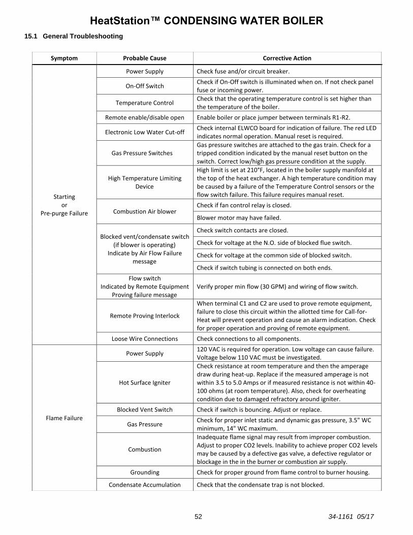
HeatStation™ CONDENSING WATER BOILER
52 34-1161 05/17
15.1 General Troubleshooting
Symptom Probable Cause Corrective Action
Starting or
Pre-purge Failure
Power Supply Check fuse and/or circuit breaker.
On-Off Switch Check if On-Off switch is illuminated when on. If not check panel fuse or incoming power.
Temperature Control Check that the operating temperature control is set higher than the temperature of the boiler.
Remote enable/disable open Enable boiler or place jumper between terminals R1-R2.
Electronic Low Water Cut-off Check internal ELWCO board for indication of failure. The red LED indicates normal operation. Manual reset is required.
Gas Pressure Switches Gas pressure switches are attached to the gas train. Check for a tripped condition indicated by the manual reset button on the switch. Correct low/high gas pressure condition at the supply.
High Temperature Limiting Device
High limit is set at 210°F, located in the boiler supply manifold at the top of the heat exchanger. A high temperature condition may be caused by a failure of the Temperature Control sensors or the flow switch failure. This failure requires manual reset.
Combustion Air blower Check if fan control relay is closed.
Blower motor may have failed.
Blocked vent/condensate switch (if blower is operating)
Indicate by Air Flow Failure message
Check switch contacts are closed.
Check for voltage at the N.O. side of blocked flue switch.
Check for voltage at the common side of blocked switch.
Check if switch tubing is connected on both ends.
Flow switch Indicated by Remote Equipment
Proving failure message Verify proper min flow (30 GPM) and wiring of flow switch.
Remote Proving Interlock
When terminal C1 and C2 are used to prove remote equipment, failure to close this circuit within the allotted time for Call-for-Heat will prevent operation and cause an alarm indication. Check for proper operation and proving of remote equipment.
Loose Wire Connections Check connections to all components.
Flame Failure
Power Supply 120 VAC is required for operation. Low voltage can cause failure. Voltage below 110 VAC must be investigated.
Hot Surface Igniter
Check resistance at room temperature and then the amperage draw during heat-up. Replace if the measured amperage is not within 3.5 to 5.0 Amps or if measured resistance is not within 40-100 ohms (at room temperature). Also, check for overheating condition due to damaged refractory around igniter.
Blocked Vent Switch Check if switch is bouncing. Adjust or replace.
Gas Pressure Check for proper inlet static and dynamic gas pressure, 3.5" WC minimum, 14" WC maximum.
Combustion
Inadequate flame signal may result from improper combustion. Adjust to proper CO2 levels. Inability to achieve proper CO2 levels may be caused by a defective gas valve, a defective regulator or blockage in the in the burner or combustion air supply.
Grounding Check for proper ground from flame control to burner housing.
Condensate Accumulation Check that the condensate trap is not blocked.
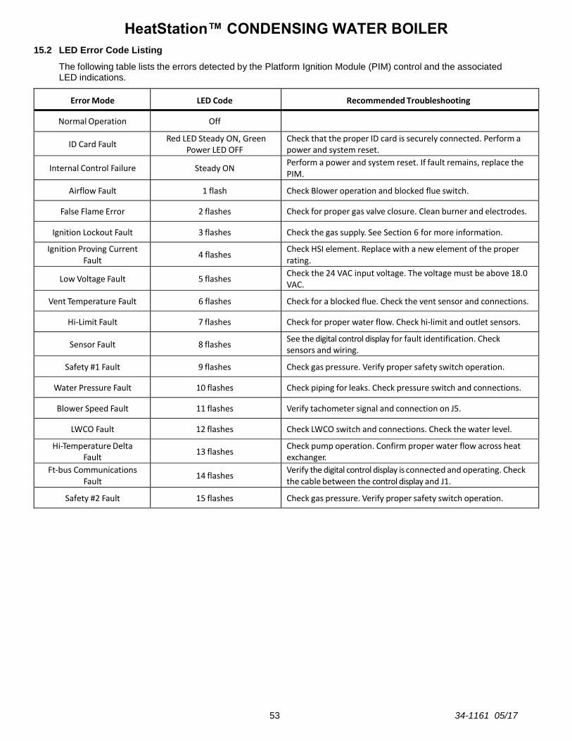
HeatStation™ CONDENSING WATER BOILER
53 34-1161 05/17
15.2 LED Error Code Listing
The following table lists the errors detected by the Platform Ignition Module (PIM) control and the associated LED indications.
Error Mode LED Code Recommended Troubleshooting
Normal Operation Off
ID Card Fault Red LED Steady ON, Green
Power LED OFF Check that the proper ID card is securely connected. Perform a power and system reset.
Internal Control Failure Steady ON Perform a power and system reset. If fault remains, replace the PIM.
Airflow Fault 1 flash Check Blower operation and blocked flue switch.
False Flame Error 2 flashes Check for proper gas valve closure. Clean burner and electrodes.
Ignition Lockout Fault 3 flashes Check the gas supply. See Section 6 for more information.
Ignition Proving Current Fault
4 flashes Check HSI element. Replace with a new element of the proper rating.
Low Voltage Fault 5 flashes Check the 24 VAC input voltage. The voltage must be above 18.0 VAC.
Vent Temperature Fault 6 flashes Check for a blocked flue. Check the vent sensor and connections.
Hi-Limit Fault 7 flashes Check for proper water flow. Check hi-limit and outlet sensors.
Sensor Fault 8 flashes See the digital control display for fault identification. Check sensors and wiring.
Safety #1 Fault 9 flashes Check gas pressure. Verify proper safety switch operation.
Water Pressure Fault 10 flashes Check piping for leaks. Check pressure switch and connections.
Blower Speed Fault 11 flashes Verify tachometer signal and connection on J5.
LWCO Fault 12 flashes Check LWCO switch and connections. Check the water level.
Hi-Temperature Delta Fault
13 flashes Check pump operation. Confirm proper water flow across heat exchanger.
Ft-bus Communications Fault
14 flashes Verify the digital control display is connected and operating. Check the cable between the control display and J1.
Safety #2 Fault 15 flashes Check gas pressure. Verify proper safety switch operation.

HeatStation™ CONDENSING WATER BOILER
54 34-1161 05/17
16 REPLACEMENT PARTS
16.1 Blower & Burner Assembly (Optional components may not be shown)
ITEM DESCRIPTION HS 1000 HS 1250 HS 1500 HS 1750 HS 2000
1 ASSY,TRANSITION BURNER/BLOWER 1000-1250 HS GRAY 127694 127694 - - -
1 ASSY,TRANSITION BURNER/BLOWER 1500-2000 HS GRAY - - 127695 127695 127695
2 BLOWER, EBMPAPST #55600.03051 G3G200 126337 126337 - - -
2 BLOWER,EBMPAPST #55600.05051 G3G250 - - 126338 126338 126338
3 BURNER, WORGAS 140 X 310 MM 126852 126852 - - -
3 BURNER,WORGAS 140 X 648 MM - - 125559 125559 125559
4 INTAKE,AIR DUNGS WHIRLWIND 126864 126864 126864 - -
4 INTAKE,AIR DUNGS WHIRLWIND - - - 126895 126895
5 ADAPTER,FLEXIBLE RUBBER 6 X 5 126849 126849 126849 - -
5 ADAPTER,FLEXIBLE RUBBER 8 X 6 - - - 127733 127733
6 GASKET,SILICONE FOR G3G200 BLOWER 127710 127710 - - -
6 GASKET,SILICONE FOR G3G250 BLOWER - - 127711 127711 127711
7 GASKET, BURNER FLANGE 1/8 232 CRANEGLAS 126509 126509 126509 126509 126509
8 GASKET, IGNITOR 1/8 232 CRANEGLAS 111791 111791 111791 111791 111791
9 IGNITER, HOT SURFACE NORTON 107775 107775 107775 107775 107775
10 ELECTRODE, FLAME WITH 1/2 X 14 GLAND NUT 127816 127816 127816 127816 127816
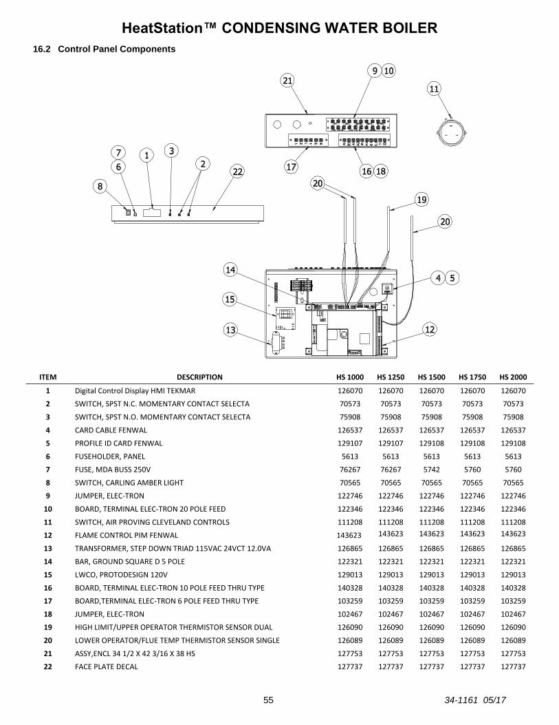
HeatStation™ CONDENSING WATER BOILER
55 34-1161 05/17
16.2 Control Panel Components
ITEM DESCRIPTION HS 1000 HS 1250 HS 1500 HS 1750 HS 2000
1 Digital Control Display HMI TEKMAR 126070 126070 126070 126070 126070
2 SWITCH, SPST N.C. MOMENTARY CONTACT SELECTA 70573 70573 70573 70573 70573
3 SWITCH, SPST N.O. MOMENTARY CONTACT SELECTA 75908 75908 75908 75908 75908
4 CARD CABLE FENWAL 126537 126537 126537 126537 126537
5 PROFILE ID CARD FENWAL 129107 129107 129108 129108 129108
6 FUSEHOLDER, PANEL 5613 5613 5613 5613 5613
7 FUSE, MDA BUSS 250V 76267 76267 5742 5760 5760
8 SWITCH, CARLING AMBER LIGHT 70565 70565 70565 70565 70565
9 JUMPER, ELEC-TRON 122746 122746 122746 122746 122746
10 BOARD, TERMINAL ELEC-TRON 20 POLE FEED 122346 122346 122346 122346 122346
11 SWITCH, AIR PROVING CLEVELAND CONTROLS 111208 111208 111208 111208 111208
12 FLAME CONTROL PIM FENWAL 143623 143623 143623 143623 143623
13 TRANSFORMER, STEP DOWN TRIAD 115VAC 24VCT 12.0VA 126865 126865 126865 126865 126865
14 BAR, GROUND SQUARE D 5 POLE 122321 122321 122321 122321 122321
15 LWCO, PROTODESIGN 120V 129013 129013 129013 129013 129013
16 BOARD, TERMINAL ELEC-TRON 10 POLE FEED THRU TYPE 140328 140328 140328 140328 140328
17 BOARD,TERMINAL ELEC-TRON 6 POLE FEED THRU TYPE 103259 103259 103259 103259 103259
18 JUMPER, ELEC-TRON 102467 102467 102467 102467 102467
19 HIGH LIMIT/UPPER OPERATOR THERMISTOR SENSOR DUAL 126090 126090 126090 126090 126090
20 LOWER OPERATOR/FLUE TEMP THERMISTOR SENSOR SINGLE 126089 126089 126089 126089 126089
21 ASSY,ENCL 34 1/2 X 42 3/16 X 38 HS 127753 127753 127753 127753 127753
22 FACE PLATE DECAL 127737 127737 127737 127737 127737
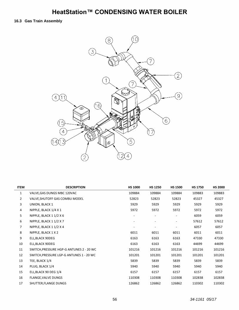
HeatStation™ CONDENSING WATER BOILER
56 34-1161 05/17
16.3 Gas Train Assembly
ITEM DESCRIPTION HS 1000 HS 1250 HS 1500 HS 1750 HS 2000
1 VALVE,GAS DUNGS MBC 120VAC 109884 109884 109884 109883 109883
2 VALVE,SHUTOFF GAS COMBU MODEL 52823 52823 52823 45327 45327
3 UNION, BLACK 1 5929 5929 5929 5929 5929
4 NIPPLE, BLACK 1/4 X 1 5972 5972 5972 5972 5972
5 NIPPLE, BLACK 1 1/2 X 6 - - - 6059 6059
6 NIPPLE, BLACK 1 1/2 X 7 - - - 57612 57612
7 NIPPLE, BLACK 1 1/2 X 4 - - - 6057 6057
8 NIPPLE, BLACK 1 X 2 6011 6011 6011 6011 6011
9 ELL,BLACK 90DEG 6163 6163 6163 47330 47330
10 ELL,BLACK 90DEG 6163 6163 6163 44699 44699
11 SWITCH,PRESSURE HGP-G ANTUNES 2 - 20 WC 101216 101216 101216 101216 101216
12 SWITCH,PRESSURE LGP-G ANTUNES 1 - 20 WC 101201 101201 101201 101201 101201
13 TEE, BLACK 1/4 5839 5839 5839 5839 5839
14 PLUG, BLACK 1/4 5940 5940 5940 5940 5940
15 ELL,BLACK 90 DEG 1/4 6157 6157 6157 6157 6157
16 FLANGE,VALVE DUNGS 110308 110308 110308 102838 102838
17 SHUTTER,FLANGE DUNGS 126862 126862 126862 110302 110302
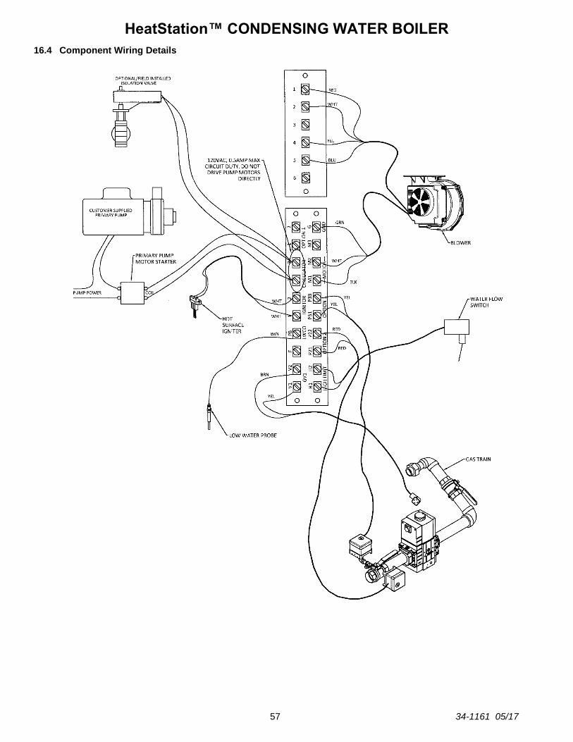
HeatStation™ CONDENSING WATER BOILER
57 34-1161 05/17
16.4 Component Wiring Details

HeatStation™ CONDENSING WATER BOILER
58 34-1161 05/17
17 PERIODIC MAINTENANCE
Listed below are items that must be checked to ensure reliable operations. Maintenance must be performed by a qualified service or maintenance provider. To ensure proper maintenance, the following instructions should be posted near the appliance and maintained in legible condition. Verify proper operation after servicing. WARNING: When servicing the controls, use exact, Factory authorized, replacement parts and label all wires prior to disconnection. Verify proper operation after servicing. Incorrect parts substitution and wiring errors can cause damage, improper operation, fire, carbon monoxide, exposure to toxic fumes or other unexpected and unsafe conditions that can result in fire, personal injury or death. 1. Examine the appliance and venting system at least once a year. Check more often in first year to determine
inspection interval.
a. Check all joints and pipe connections for tightness, corrosion or deterioration.
b. Check the electronic-ignition system for quick ignition and a proper flame signal.
c. Check all safety controls including thermostats for proper operation.
d. Check safety shut-off valves for operation and tightness.
e. Have the entire system, including, but not limited to, the burner, heat exchanger and venting system, periodically inspected by a qualified service agency.
2. Exposure to Dusty or Dirty Combustion Air: An appliance installed in a dust or dirt contaminated atmosphere will require more frequent inspection and cleaning of the burner to prevent nuisance shutdowns or premature burner failure.
3. Any sign of soot on the heat exchanger or in the flue indicates the need for a combustion inspection. Properly installed and adjusted units seldom need heat exchanger cleaning. If soot has formed, the most common causes are restricted combustion air or excessive gas. A blocked heat exchanger can cause unsafe operation and will reduce efficiency. To inspect and clean the heat exchanger, a qualified service agent or installer should use the procedures described in items 4, 5 & 6 below.
4. All gaskets on disassembled components must be replaced on reassembly with exact, Factory Authorized, replacement parts only. Gasket kits are available from your Riverside Hydronics Representative or by contacting Riverside Hydronics.
5. Burner and/or Heat Exchanger Inspection and Cleaning Procedure:
a. Turn off main power to unit.
b. Turn off gas supply.
c. Write notes and/or take pictures during this process to aid in correct reassembly.
d. Disconnect electrical components by disconnecting the wires going to terminal strip in the bottom junction box and the respective conduit connections on the bottom of the control enclosure. If a wiring diagram is not attached to the back of the enclosure door or otherwise provided with the boiler, make careful notes of the locations for all the wires.
e. Remove the metal jacket panels, as needed, by disconnecting the fasteners holding it to the structural frame and other panels.
f. Remove the hot surface igniter, (HSI) from the burner. Be very careful not to bump the igniter element due to the fragility of the igniter.
g. Break the unions that connect the gas train to the blower and the gas supply pipe. Remove the gas train.
h. Remove the nuts that secure the burner transition to the combustion chamber and pull the blower/burner assembly out until it is completely extracted from boiler.
i. Inspect refractory for damage. The refractory must provide a tight seal against the top edge of the burner deck. Be careful not to damage the refractory when removing the burner. With the burner removed, inspect the deck surface of the burner for lint or other blockage carried in the fuel air stream. If blockage has accumulated, use brush to loosen debris and use a vacuum or water to remove it from the burner cavities.
j. Inspect the burner surface for signs of cracking or thermal fatigue.
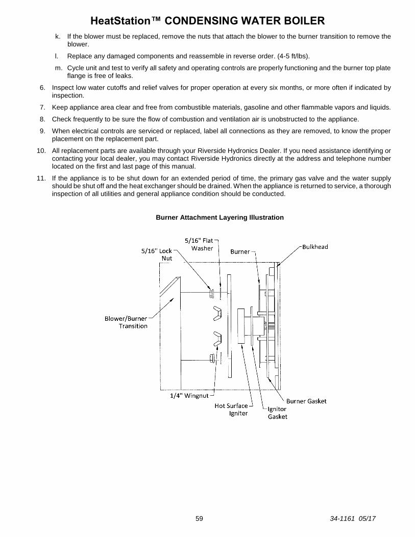
HeatStation™ CONDENSING WATER BOILER
59 34-1161 05/17
k. If the blower must be replaced, remove the nuts that attach the blower to the burner transition to remove the blower.
l. Replace any damaged components and reassemble in reverse order. (4-5 ft/lbs).
m. Cycle unit and test to verify all safety and operating controls are properly functioning and the burner top plate flange is free of leaks.
6. Inspect low water cutoffs and relief valves for proper operation at every six months, or more often if indicated by inspection.
7. Keep appliance area clear and free from combustible materials, gasoline and other flammable vapors and liquids.
8. Check frequently to be sure the flow of combustion and ventilation air is unobstructed to the appliance.
9. When electrical controls are serviced or replaced, label all connections as they are removed, to know the proper placement on the replacement part.
10. All replacement parts are available through your Riverside Hydronics Dealer. If you need assistance identifying or contacting your local dealer, you may contact Riverside Hydronics directly at the address and telephone number located on the first and last page of this manual.
11. If the appliance is to be shut down for an extended period of time, the primary gas valve and the water supply should be shut off and the heat exchanger should be drained. When the appliance is returned to service, a thorough inspection of all utilities and general appliance condition should be conducted.
Burner Attachment Layering Illustration
HeatStation™ CONDENSING WATER BOILER
60 34-1161 05/17
18 RECOMMENDED MAINTENANCE SCHEDULE
Regular service by a qualified service agency and routine maintenance must be performed to ensure safe, reliable and efficient operation. Yearly (Every 12 Months)
Schedule annual service call by qualified service agency.
1. Check for piping leaks around pumps, relief valves, and boiler connections. Repair, if found.
2. Check to ensure area is free from combustible materials, gasoline, and other flammable vapors or liquids.
3. Visually inspect venting system for proper function, deterioration or leakage.
4. Check pressure relief valve. Refer to manufacturer’s instructions on valve.
5. Inspect condensate drain and ensure condensate is directed to an appropriate condensate system or drain, as required by local codes.
6. Check all operation of safety devices. Refer to manufacturer’s instructions.
7. Inspect burner and gas train components for wear or deterioration.
8. Check the electronic-ignition system for quick ignition and proper flame signal.
9. Check gas safety shut-off valves for proper operation and tightness.
10. Follow startup procedure in the Installation & Maintenance Manual.
Semi-Annually (Every Six Months)
1. Test Low-water-cut-off (if equipped). Refer to manufacturer’s instructions and reset.
2. Test the electronic-ignition flame failure detection system. Refer to manufacturer’s instructions and reset.
Monthly
1. Check condensate drain system and refill the condensate neutralizer with limestone (change interval as needed).
2. Visually inspect venting system for proper function, deterioration or leakage.
3. Confirm the low-water cutoff and alarm are operating.
Daily
1. Check for and remove any obstruction to the flow of combustion or ventilation air to the unit.
2. Check to ensure area is free from combustible materials, gasoline, and other flammable vapors or liquids.
3. Check gauges, monitors and indicators.
As Required
1. Flush and clean heat exchanger as required.

HeatStation™ CONDENSING WATER BOILER
61 34-1161 05/17
HeatStation™ CONDENSING WATER BOILER
62 34-1161 05/17
Since Riverside Hydronics cannot control the use of the appliance, water conditions, or maintenance, the warranty on the heat exchanger does not cover poor performance, structural failure, or leaking due to an excessive accumulation of scale.
MODEL NUMBER:
SERIAL NUMBER:
INSTALLATION DATE:
Riverside Hydronics® 3209 Galvez Ave. Fort Worth, Texas 76111 Phone 1-800-990-5918 www.riversidehydronics.com