Heating and cooling with ceilings - Krantz
12
2 Technical Report Cooling and heating systems Heating and cooling with ceilings
Transcript of Heating and cooling with ceilings - Krantz
2
Tech
nic
al
Re
po
rt
C o o l i n g a n d h e a t i n g s y s t e m sHeating and cooling with ceilings
Heating and cooling with ceilings
2
Jürgen Nickel* The original misgivings towards water piping inceilings directly above the workplace, withattendant fears of possible leakage, condensa-tion, unpleasant coldness, etc. have generallygiven way to a high level of acceptance. Today,there is a widespread interest in extending therange of application to heating, in order to saveon investment costs on the one hand and onthe other to dispense with static heaters underor in front of glass facades, which are oftenundesirable for architectural reasons.
We should recall, however, that alreadydecades ago radiant heating from the ceilingwas quite common, but due to user dissatisfac-tion it largely disappeared from the market,apart from industrial applications. Unlike cool-ing, heating can quickly exceed comfort limits.
When specifying the layout of active ceiling systems for room cooling, the prime concern isalmost always the maximum removable coolingload, while thermal comfort is practicallyalways assured, as years of practice have nowconfirmed. Decisive for cooling capacity is theflow temperature, which has a minimum limit,due to the condensation risk.
Generally, cooling ceiling operation is designedto prevent condensation of indoor air at anypoint in the system. Due to the usual outsideand indoor air conditions cooling ceilings aretherefore mostly run at minimum flow tempera-tures of 15°C to 16°C. Mean ceiling surfacetemperatures are accordingly about 17°C to19°C and are experienced as pleasant by occu-pants.
The permissible limit values to DIN 1946, P. 2for the asymmetric radiation of a cooling ceilingare also always maintained.
Due to natural thermal convective flow in cool-ing ceiling operation a very even air tempera-ture distribution forms in the room with normalminimum fluctuations of under ± 0.5 K overthe entire room height.
Cooling function
* Jürgen Nickel, Research & Development, AachenKrantz Technology GmbH, 52072 Aachen
Special publication from the TAB No. 05/97, page 41 - 48
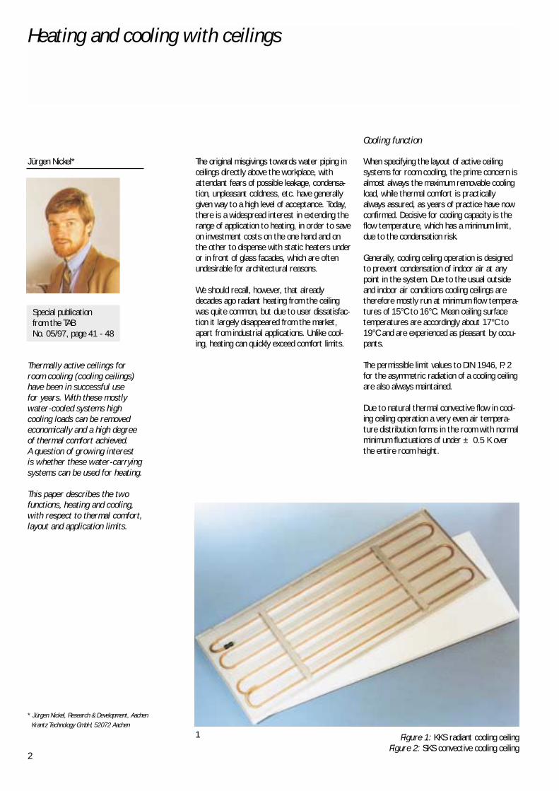
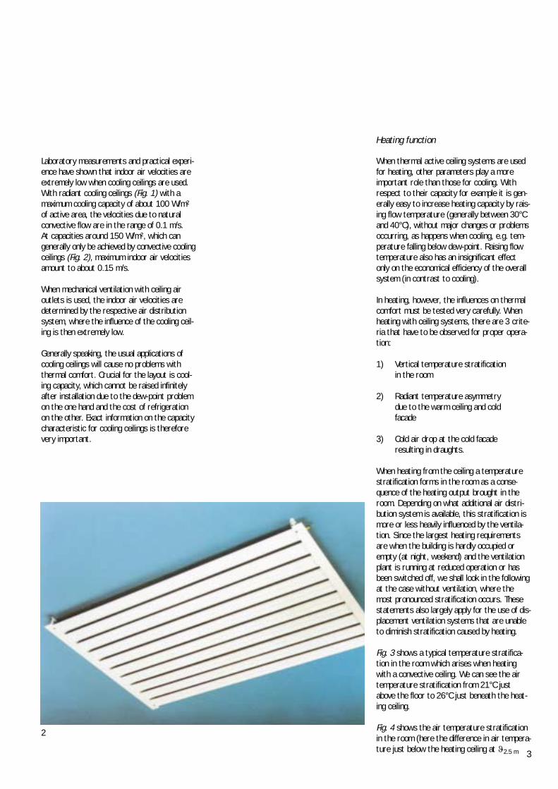
Figure 1: KKS radiant cooling ceiling Figure 2: SKS convective cooling ceiling
1
Thermally active ceilings forroom cooling (cooling ceilings)have been in successful use for years. With these mostlywater-cooled systems high cooling loads can be removedeconomically and a high degreeof thermal comfort achieved. A question of growing interest is whether these water-carryingsystems can be used for heating.
This paper describes the twofunctions, heating and cooling,with respect to thermal comfort,layout and application limits.
3
Laboratory measurements and practical experi-ence have shown that indoor air velocities areextremely low when cooling ceilings are used.With radiant cooling ceilings (Fig. 1) with amaximum cooling capacity of about 100 W/m²of active area, the velocities due to naturalconvective flow are in the range of 0.1 m/s. At capacities around 150 W/m², which cangenerally only be achieved by convective coolingceilings (Fig. 2), maximum indoor air velocitiesamount to about 0.15 m/s.
When mechanical ventilation with ceiling airoutlets is used, the indoor air velocities aredetermined by the respective air distributionsystem, where the influence of the cooling ceil-ing is then extremely low.
Generally speaking, the usual applications ofcooling ceilings will cause no problems withthermal comfort. Crucial for the layout is cool-ing capacity, which cannot be raised infinitelyafter installation due to the dew-point problemon the one hand and the cost of refrigerationon the other. Exact information on the capacitycharacteristic for cooling ceilings is thereforevery important.
2
When thermal active ceiling systems are usedfor heating, other parameters play a moreimportant role than those for cooling. Withrespect to their capacity for example it is gen-erally easy to increase heating capacity by rais-ing flow temperature (generally between 30°Cand 40°C), without major changes or problemsoccurring, as happens when cooling, e.g. tem-perature falling below dew-point. Raising flowtemperature also has an insignificant effectonly on the economical efficiency of the overallsystem (in contrast to cooling).
In heating, however, the influences on thermalcomfort must be tested very carefully. Whenheating with ceiling systems, there are 3 crite-ria that have to be observed for proper opera-tion:
1) Vertical temperature stratification in the room
2) Radiant temperature asymmetrydue to the warm ceiling and coldfacade
3) Cold air drop at the cold facade resulting in draughts.
When heating from the ceiling a temperaturestratification forms in the room as a conse-quence of the heating output brought in theroom. Depending on what additional air distri-bution system is available, this stratification ismore or less heavily influenced by the ventila-tion. Since the largest heating requirementsare when the building is hardly occupied orempty (at night, weekend) and the ventilationplant is running at reduced operation or hasbeen switched off, we shall look in the followingat the case without ventilation, where themost pronounced stratification occurs. Thesestatements also largely apply for the use of dis-placement ventilation systems that are unableto diminish stratification caused by heating.
Fig. 3 shows a typical temperature stratifica-tion in the room which arises when heatingwith a convective ceiling. We can see the airtemperature stratification from 21°C justabove the floor to 26°C just beneath the heat-ing ceiling.
Fig. 4 shows the air temperature stratificationin the room (here the difference in air tempera-ture just below the heating ceiling at �2.5 m
Heating function
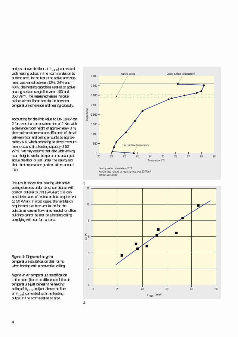
4
and just above the floor at �0.1 m) correlatedwith heating output in the room in relation tosurface area. In the tests the active area seg-ment was varied between 12%, 24% and48%; the heating capacities related to activeheating surface ranged between 100 and 350 W/m². The measured values indicate a clear almost linear correlation between temperature difference and heating capacity.
Accounting for the limit value to DIN 1946/Part2 for a vertical temperature rise of 2 K/m witha clearance room height of approximately 3 m,the maximum temperature difference of the airbetween floor and ceiling amounts to approxi-mately 6 K, which according to these measure-ments occurs at a heating capacity of 50W/m². We may assume that also with varyingroom heights similar temperatures occur justabove the floor or just under the ceiling andthat the temperature gradient alters accord-ingly.
This result shows that heating with active ceiling elements under strict compliance withcomfort criteria to DIN 1946/Part 2 is onlypossible in cases of restricted heat requirement(� 50 W/m²). In most cases, the ventilationrequirements at free ventilation for the outside air volume flow rates needed for officebuildings cannot be met by a heating ceilingcomplying with comfort criteria.
3
Figure 3: Diagram of a typical temperature stratification that forms when heating with a convective ceiling
Figure 4: Air temperature stratification in the room (here the difference of the air temperature just beneath the heating ceiling of �2.5 m and just above the floor of �0.1 m) correlated with the heating output in the room related to area
4
5
5
6
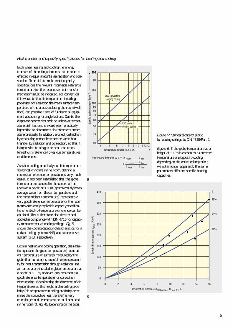
Figure 5: Standard characteristic for cooling ceilings to DIN 4715/Part 1
Figure 6: If the globe temperature at a height of 1.1 m is chosen as a reference temperature analogous to cooling, depending on the active ceiling ratio �we obtain under apparently the same parameters different specific heating capacities
Heat transfer and capacity specifications for heating and cooling
Both when heating and cooling the energytransfer of the ceiling elements to the room iseffected in equal amounts via radiation and con-vection. To be able to make exact capacityspecifications the relevant room-side referencetemperature for the respective heat transfermechanism must be indicated. For convection,this would be the air temperature in ceilingproximity, for radiation the mean surface tem-perature of the areas enclosing the room (wall,floor) and possible items of furniture or equip-ment accounting for angle factors. Due to thedisparate geometries and the unknown temper-ature distributions, it would seem practicallyimpossible to determine this reference temper-ature precisely. In addition, a direct distinctionby measuring cannot be made between heattransfer by radiation and convection, so that itis impossible to assign the heat load trans-ferred with reference to various temperaturesor differences.
As when cooling practically no air temperaturestratification forms in the room, defining aroom-side reference temperature is very mucheasier. It has been established that the globetemperature measured in the centre of theroom at a height of 1.1 m (approximately meanaverage value from the air temperature andthe mean radiant temperature) represents avery good reference temperature for the room,from which easily replicable capacity specifica-tions related to temperature difference can beobtained. This is therefore also the methodapplied in compliance with DIN 4715 for capaci-ty measurement at cooling ceilings. Fig. 5shows the cooling capacity characteristics for aradiant ceiling system (KKS) and a convectivesystem (SKS), respectively.
Both in heating and cooling operation, the radia-tion quota in the globe temperature (mean radi-ant temperature of surfaces measured by theglobe thermometer) is a useful reference quanti-ty for heat transmission through radiation. Theair temperature included in globe temperature ata height of 1.1 m, however, only represents agood reference temperature for convectionwhen cooling. When heating the difference of airtemperatures at this height and in ceiling prox-imity (air temperature in ceiling proximity deter-mines the convective heat transfer) is verymuch larger and depends on the total heat loadin the room (cf. Fig. 4). Depending on the total
6
load in the room at the same globe tempera-tures in ceiling proximity, this can result in vari-ous air temperatures and thus various convec-tive capacities, which is not accounted for inglobe temperature.
If we choose the globe temperature at a heightof 1.1 m as a reference temperature analogousto cooling, depending on the active ceiling frac-tion (share of active ceiling segment in theoverall surface) we obtain under apparently thesame parameters (same surface temperatureand same globe temperature at 1.1 m height)different specific heating capacities, as shownin Fig. 6.
We can see a strong correlation of heat outputat the same temperature difference with activeceiling ratio (here 12%, 24%, 48%). The rea-son for the dependence of capacity on activeceiling ratio are the increasing vertical temper-ature gradients in the room. At higher activeceiling ratio, total heating capacity rises in theroom and consequently (see Fig. 4) the tem-perature stratification, so that as a result ofthe higher air temperature in the ceiling zonethe convective capacity quota drops sharply.
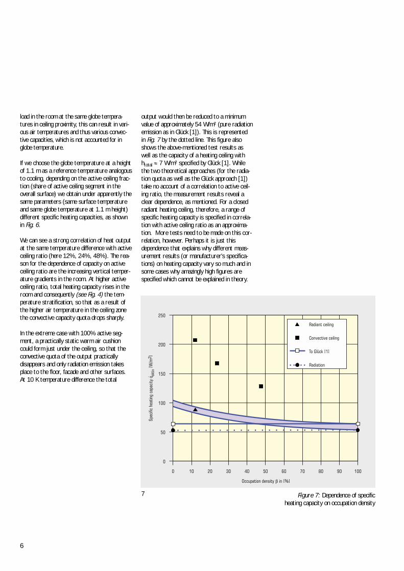
In the extreme case with 100% active seg-ment, a practically static warm air cushioncould form just under the ceiling, so that theconvective quota of the output practically disappears and only radiation emission takesplace to the floor, facade and other surfaces. At 10 K temperature difference the total
7 Figure 7: Dependence of specific heating capacity on occupation density
output would then be reduced to a minimumvalue of approximately 54 W/m² (pure radiationemission as in Glück [1]). This is represented in Fig. 7 by the dotted line. This figure alsoshows the above-mentioned test results aswell as the capacity of a heating ceiling with htotal � 7 W/m² specified by Glück [1]. Whilethe two theoretical approaches (for the radia-tion quota as well as the Glück approach [1])take no account of a correlation to active ceil-ing ratio, the measurement results reveal aclear dependence, as mentioned. For a closedradiant heating ceiling, therefore, a range ofspecific heating capacity is specified in correla-tion with active ceiling ratio as an approxima-tion. More tests need to be made on this cor-relation, however. Perhaps it is just thisdependence that explains why different meas-urement results (or manufacturer's specifica-tions) on heating capacity vary so much and insome cases why amazingly high figures arespecified which cannot be explained in theory.
7
The task of room heating is not only to providethe room with the necessary heating capacityto reach a corresponding air temperature; itmust also cater for comfortable radiant tem-perature conditions. On the one hand, suitablywarm surfaces near the facade are supposedto offset the uncomfortable 'cold emission' fromthe window and on the other the heatingshould not result in unpleasant heat radiationon the occupants. In addition, the operativetemperature (= felt temperature) should notvary too much, which is possible with wide sur-face temperature differences. In general, a con-ventional placement of heaters in the parapetof the facades performs these tasks very well,because the radiation effects are equalized dueto the immediate proximity of the cold surface(windows) and the warm surface (heaters).
Various experiments show that when usingheating ceilings, the best conditions can beobtained by using ceiling strips only about 1 to2 m broad at the facade with somewhat highertemperatures (compared with large-surfaceinstallation covering the whole room).
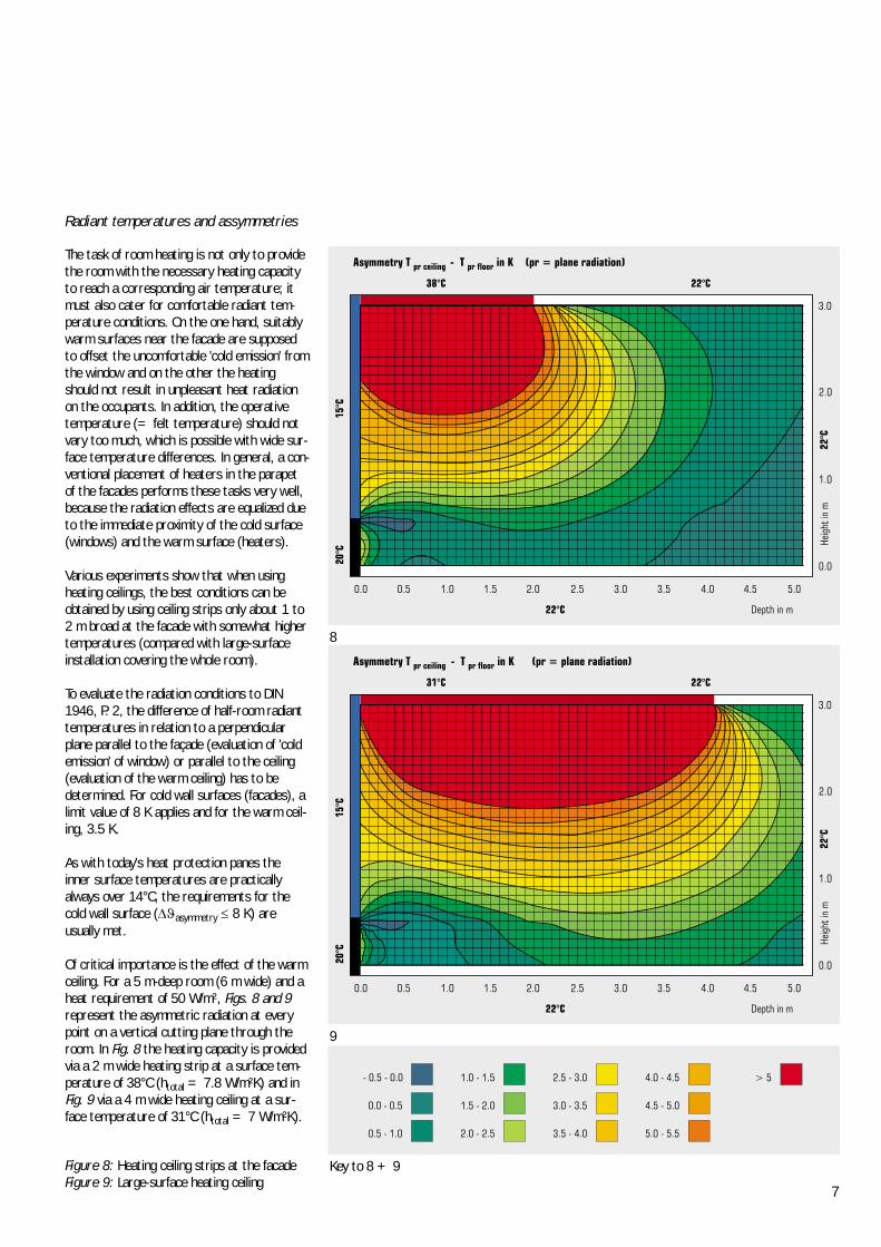
To evaluate the radiation conditions to DIN1946, P. 2, the difference of half-room radianttemperatures in relation to a perpendicularplane parallel to the façade (evaluation of 'coldemission' of window) or parallel to the ceiling(evaluation of the warm ceiling) has to bedetermined. For cold wall surfaces (facades), alimit value of 8 K applies and for the warm ceil-ing, 3.5 K.
As with today's heat protection panes the inner surface temperatures are practicallyalways over 14°C, the requirements for thecold wall surface (��asymmetry � 8 K) are usually met.
Of critical importance is the effect of the warmceiling. For a 5 m-deep room (6 m wide) and aheat requirement of 50 W/m², Figs. 8 and 9represent the asymmetric radiation at everypoint on a vertical cutting plane through theroom. In Fig. 8 the heating capacity is providedvia a 2 m wide heating strip at a surface tem-perature of 38°C (htotal = 7.8 W/m²K) and inFig. 9 via a 4 m wide heating ceiling at a sur-face temperature of 31°C (htotal = 7 W/m²K).
9
8
Figure 8: Heating ceiling strips at the facadeFigure 9: Large-surface heating ceiling
Radiant temperatures and assymmetries
Key to 8 + 9
8
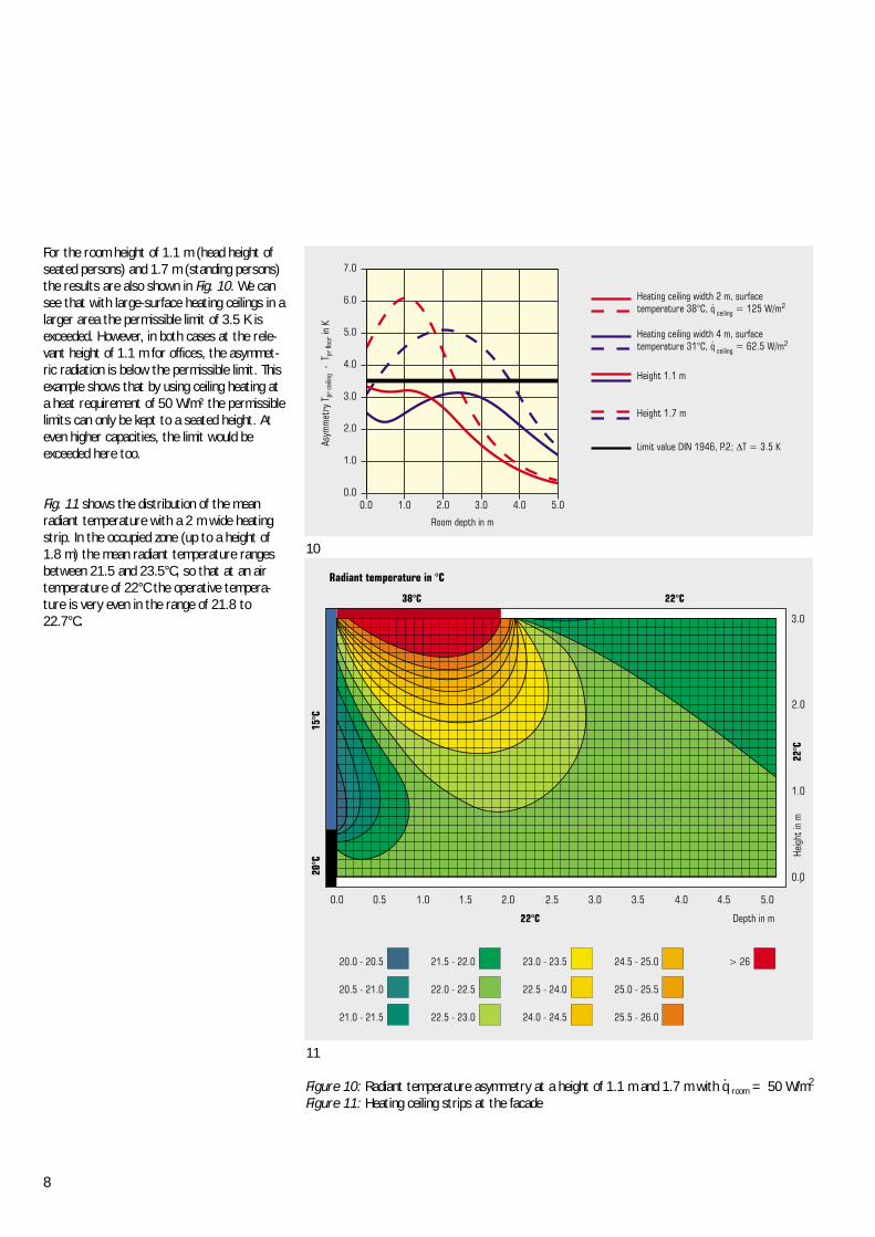
For the room height of 1.1 m (head height ofseated persons) and 1.7 m (standing persons)the results are also shown in Fig. 10. We cansee that with large-surface heating ceilings in alarger area the permissible limit of 3.5 K isexceeded. However, in both cases at the rele-vant height of 1.1 m for offices, the asymmet-ric radiation is below the permissible limit. Thisexample shows that by using ceiling heating ata heat requirement of 50 W/m² the permissiblelimits can only be kept to a seated height. Ateven higher capacities, the limit would beexceeded here too.
Fig. 11 shows the distribution of the meanradiant temperature with a 2 m wide heatingstrip. In the occupied zone (up to a height of1.8 m) the mean radiant temperature rangesbetween 21.5 and 23.5°C, so that at an airtemperature of 22°C the operative tempera-ture is very even in the range of 21.8 to22.7°C.
10
11
Figure 10: Radiant temperature asymmetry at a height of 1.1 m and 1.7 m with q room = 50 W/m2
Figure 11: Heating ceiling strips at the facade
.
9
The cold air drop at high glass facades poses alarge problem with respect to thermal comfort.The cold air drop can be effectively counteract-ed by convective heaters or window air cur-tains at the facades. Heating ceilings, however,have no direct effect on this cold air drop andcan only mitigate this problem indirectly byslightly increasing the inner surface tempera-ture in the ceiling zone of the facades.
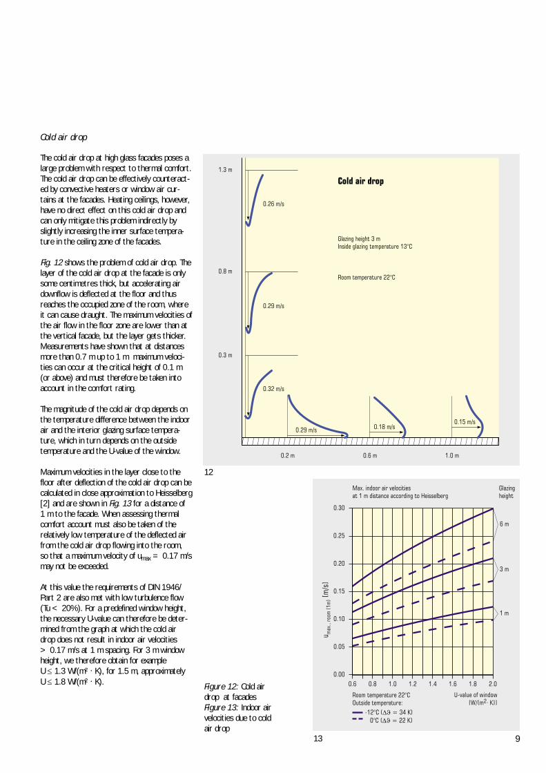
Fig. 12 shows the problem of cold air drop. Thelayer of the cold air drop at the facade is onlysome centimetres thick, but accelerating airdownflow is deflected at the floor and thusreaches the occupied zone of the room, whereit can cause draught. The maximum velocities ofthe air flow in the floor zone are lower than atthe vertical facade, but the layer gets thicker.Measurements have shown that at distancesmore than 0.7 m up to 1 m maximum veloci-ties can occur at the critical height of 0.1 m(or above) and must therefore be taken intoaccount in the comfort rating.
The magnitude of the cold air drop depends onthe temperature difference between the indoorair and the interior glazing surface tempera-ture, which in turn depends on the outsidetemperature and the U-value of the window.
Maximum velocities in the layer close to thefloor after deflection of the cold air drop can becalculated in close approximation to Heisselberg[2] and are shown in Fig. 13 for a distance of 1 m to the facade. When assessing thermalcomfort account must also be taken of the relatively low temperature of the deflected airfrom the cold air drop flowing into the room, so that a maximum velocity of umax = 0.17 m/smay not be exceeded.
At this value the requirements of DIN 1946/Part 2 are also met with low turbulence flow(Tu < 20%). For a predefined window height,the necessary U-value can therefore be deter-mined from the graph at which the cold airdrop does not result in indoor air velocities > 0.17 m/s at 1 m spacing. For 3 m windowheight, we therefore obtain for example U ��1.3 W/(m² . K), for 1.5 m, approximately U ��1.8 W/(m² . K).
12
Figure 12: Cold air drop at facadesFigure 13: Indoor air velocities due to cold air drop
Cold air drop
13
10
Active ceiling systems normally used for coolingas cooling ceilings can also be used for heatingpurposes where required. To meet the comfortrequirements, however, various parametershave to be met.
As unlike heaters in parapets heating ceilingshave no effective protection against the cold airdrop at cold facades, this cold air drop with theassociated risk of draughts often poses thelargest problem. To prevent a disruptive coldair drop glass with very low U-value must beused, depending on the height of the glazing,e.g. at h = 1.5 m U � 1.8 W/(m² . K).
In addition the heat requirement of the roommust be so low that the requisite heatingcapacity of the ceiling (related to room area)amounts to a maximum of 35 - 50 W/m². With larger heating capacities higher air tem-perature stratifications occur on the one hand(> 2 K/m at normal room height 2.5 - 3 m)and in addition the asymmetric radiation due tothe warm ceiling exceeds the permissible limitvalue. At these low heating capacities, howev-er, the heating needs at window ventilation inoffices with a sufficient air exchange can hardlybe assured (n = 1 ... 2 h-1).
Where rooms have a mechanical ventilationwith a turbulent air distribution system, the air flow produced in this way reduces temperature stratification on the one hand andincreases the convective heating capacityquota on the other, so that the indicated limit(35 - 50 W/m²) shifts significantly upwards.
Finally, the differences in layout and the application parameters for heating and coolingare tabulated.
14
15
Summary
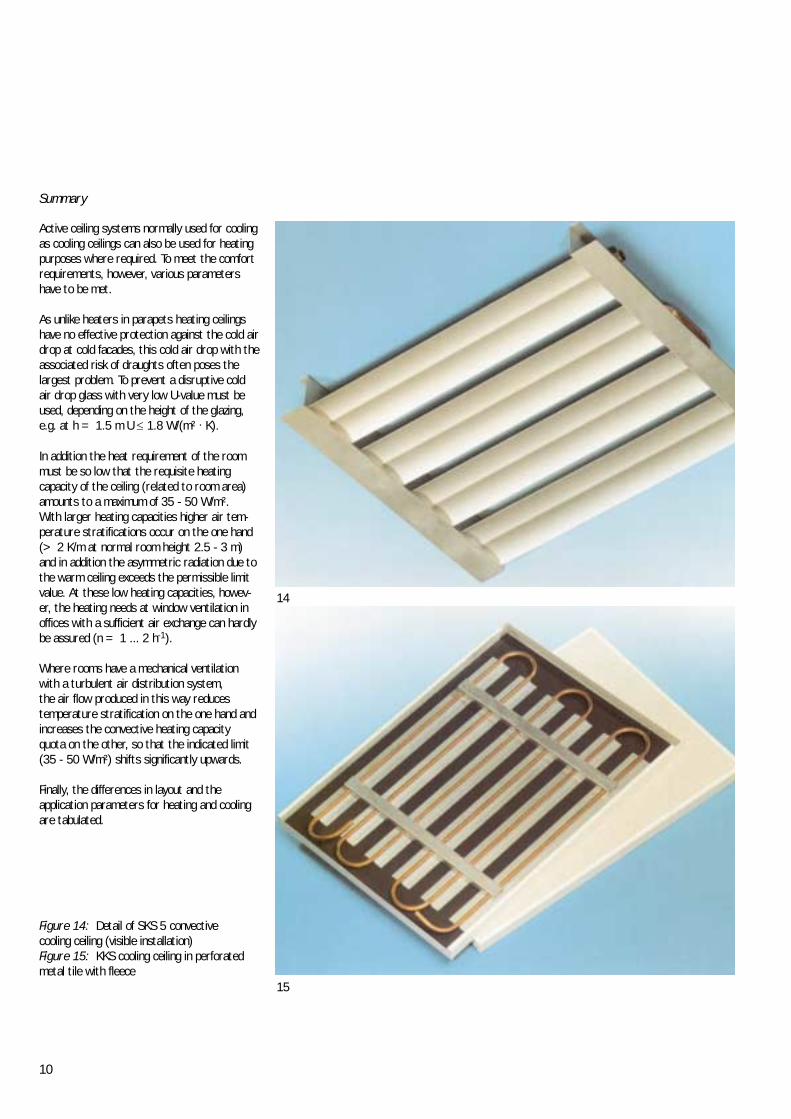
Figure 14: Detail of SKS 5 convective cooling ceiling (visible installation)Figure 15: KKS cooling ceiling in perforatedmetal tile with fleece
11
Major layout parameters
Spec. capacity
q active area
q room
Capacity specifications
Comfort criteria
Temperature stratification
Asymmetric radiation
Indoor air velocities
Limitations
q active area
q room
U-value window
Cooling
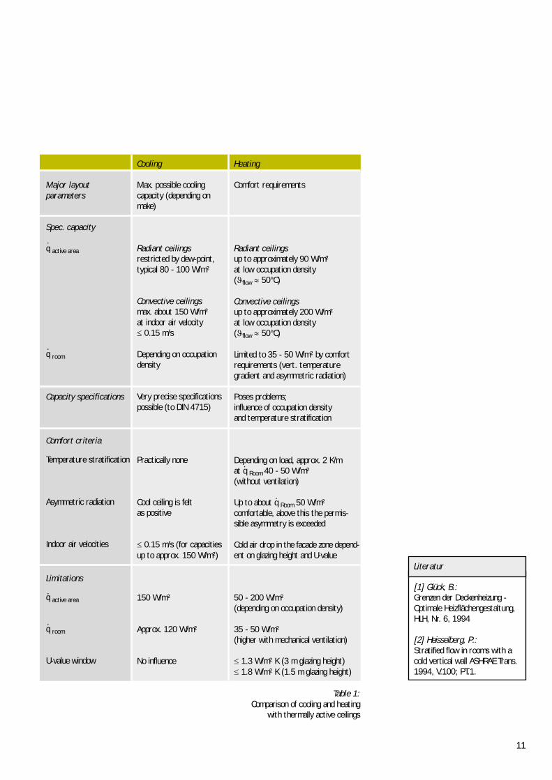
Max. possible coolingcapacity (depending onmake)
Radiant ceilings restricted by dew-point, typical 80 - 100 W/m²
Convective ceilingsmax. about 150 W/m² at indoor air velocity � 0.15 m/s
Depending on occupationdensity
Very precise specificationspossible (to DIN 4715)
Practically none
Cool ceiling is felt as positive
� 0.15 m/s (for capacitiesup to approx. 150 W/m²)
150 W/m²
Approx. 120 W/m²
No influence
Heating
Comfort requirements
Radiant ceilingsup to approximately 90 W/m² at low occupation density(�flow � 50°C)
Convective ceilingsup to approximately 200 W/m² at low occupation density(�flow � 50°C)
Limited to 35 - 50 W/m² by comfortrequirements (vert. temperature gradient and asymmetric radiation)
Poses problems; influence of occupation densityand temperature stratification
Depending on load, approx. 2 K/m at q Room 40 - 50 W/m² (without ventilation)
Up to about q Room 50 W/m² comfortable, above this the permis-sible asymmetry is exceeded
Cold air drop in the facade zone depend-ent on glazing height and U-value
50 - 200 W/m²(depending on occupation density)
35 - 50 W/m² (higher with mechanical ventilation)
� 1.3 W/m² K (3 m glazing height)� 1.8 W/m² K (1.5 m glazing height)
[1] Glück, B.: Grenzen der Deckenheizung -Optimale Heizflächengestaltung,HLH, Nr. 6, 1994
[2] Heisselberg, P.: Stratified flow in rooms with acold vertical wall ASHRAE Trans.1994, V.100; PT.1.
.
.
.
.
.
.
Literatur
Table 1:Comparison of cooling and heating
with thermally active ceilings
Tech
nica
l Rep
ort
87/2
002
e
caverion GmbHBsiness unit KRANTZ KOMPONENTENP.O.Box 10 09 53, 52009 AachenUersfeld 24, 52072 AachenGermanyPhone +49 (0)241/441-1Telefax +49 (0)241/441-555e-mail [email protected] www.krantz.de
Representatives abroad:
EUROPE
B Belgium
GB Great Britain
IRL Ireland
GR Greece
I Italy
NL Netherlands
N Norway
IS Iceland
A Austria
PL Poland
P Portugal
CH Switzerland
E Spain
CZ Czech Republic
SK Slovak Republic
HR Croatia
TR Turkey
ASIA
J Japan
SGP Singapore
ROK South Korea
OCEANIA
AUS Australia
NZ New Zealand
www.krantz.de
AFRICA
ZA Republic of South Africa
AMERICA
CDN Canada
USA United States of America
MEX Mexico
CKrantz GmbH Uersfeld 24, 52072 Aachen, GermanyPhone: +49 241 441-1, Fax: +49 241 441-555 [email protected], www.krantz.de