Heather Beam Thomas Bean Megan Chapman Steven Geiger Kimberly Keating.
40
P13045: Mobile Pediatric Stander Heather Beam Thomas Bean Megan Chapman Steven Geiger Kimberly Keating
-
Upload
derrick-doyle -
Category
Documents
-
view
214 -
download
1
Transcript of Heather Beam Thomas Bean Megan Chapman Steven Geiger Kimberly Keating.
P13045: Mobile Pediatric Stander
Heather BeamThomas Bean
Megan ChapmanSteven Geiger
Kimberly Keating

Confirm Customer Needs and Engineering Specifications
Review System Decomposition Review Concepts Introduce preliminary calculations and
assumptions Cross-disciplinary review to generate further
ideas Receive approval from customer to select
and purchase a stander
Goals for System Design Review
Work Breakdown Structure (1 min) Project Background (1 min) Customer Needs (3 min) Engineering Specs (3 min) Needs vs Specs (2 min) Functional Decomposition (5 min) Concept Generation (5 min) Concept Screening Matrices (30 min) Speed and Tipping Forces (10 min) System Architecture (13 min) Risk Assessment (5 min) Project Schedule(2 min) Questions (10 min)
Agenda
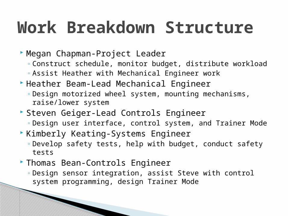
Megan Chapman-Project Leader◦ Construct schedule, monitor budget, distribute workload◦ Assist Heather with Mechanical Engineer work
Heather Beam-Lead Mechanical Engineer◦ Design motorized wheel system, mounting mechanisms,
raise/lower system Steven Geiger-Lead Controls Engineer
◦ Design user interface, control system, and Trainer Mode Kimberly Keating-Systems Engineer
◦ Develop safety tests, help with budget, conduct safety tests Thomas Bean-Controls Engineer
◦ Design sensor integration, assist Steve with control system programming, design Trainer Mode
Work Breakdown Structure
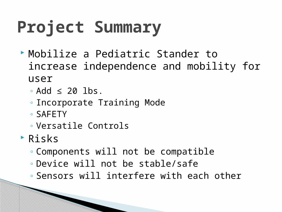
Mobilize a Pediatric Stander to increase independence and mobility for user◦ Add ≤ 20 lbs.◦ Incorporate Training Mode◦ SAFETY◦ Versatile Controls
Risks◦ Components will not be compatible◦ Device will not be stable/safe◦ Sensors will interfere with each other
Project Summary
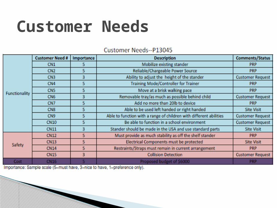
Customer Needs
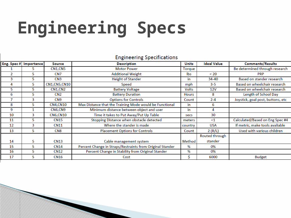
Engineering Specs
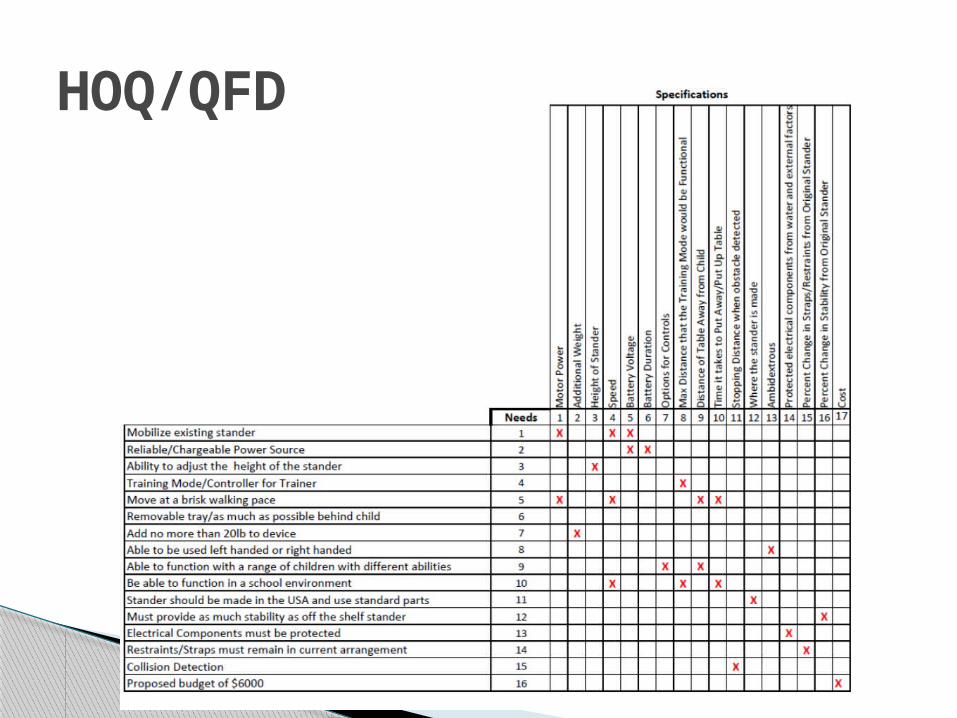
HOQ/QFD

Functional Decomposition
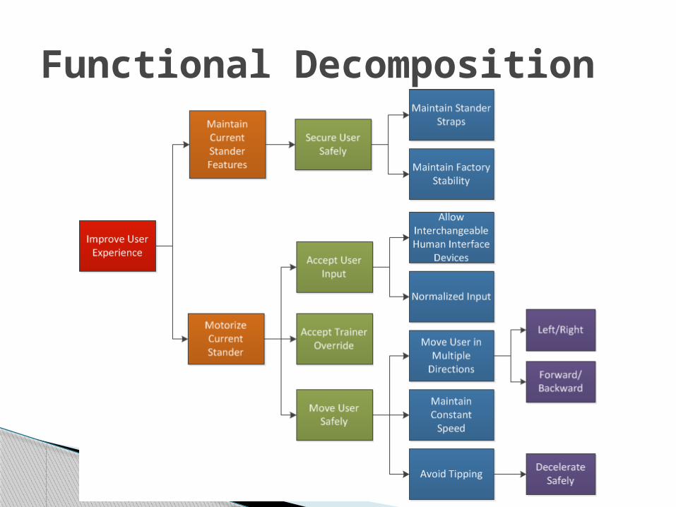
Functional Decomposition
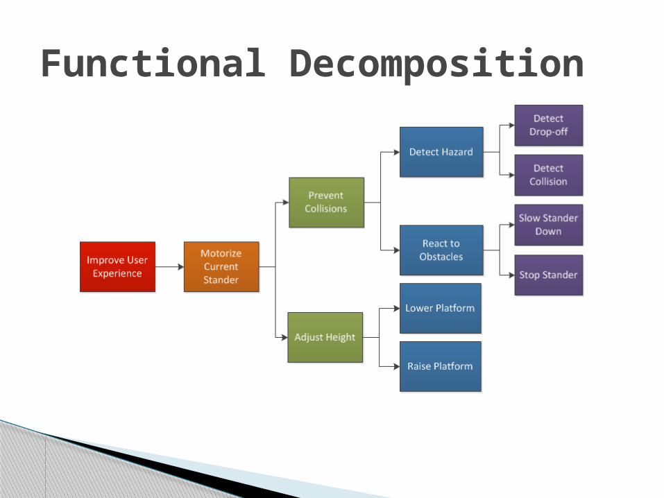
Functional Decomposition

Concept Generation
Accept User Input
Field Goal
Head Array
Joystick
Push Button Switch
Touch Screen (iPad)
Tongue Switch
Accept Trainer Override
Bluetooth
Wire Connection
Wifi
Move User SafelyMotorized Wheels
Treads
Detect Hazard
Contact Switch
Infrared Sensor
Laser Rangefinder
Thermal Imaging Sensor
Ultrasonic Sensor
Adjust Height
Hydraulic Adjustable
Pneumatic Adjustable
Power Adjustable
Stander
Rifton Dynamic Stander
Snug Seat Gecko Standing Frame
Sung Seat Rabbit Mobile Stander
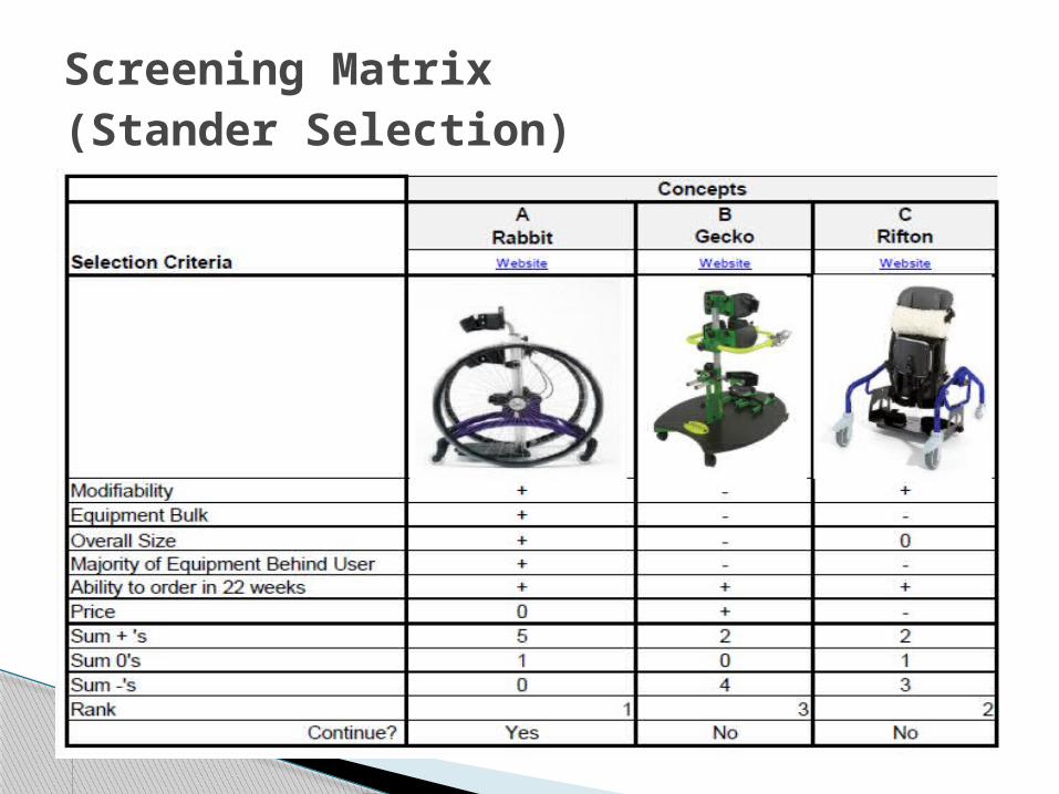
Screening Matrix (Stander Selection)
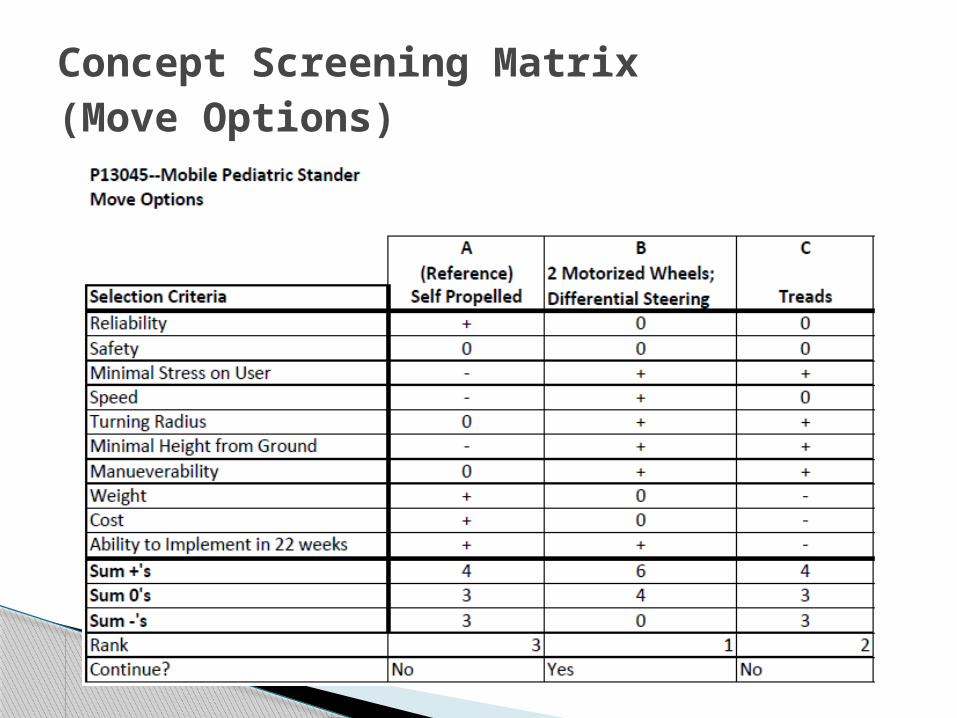
Concept Screening Matrix (Move Options)
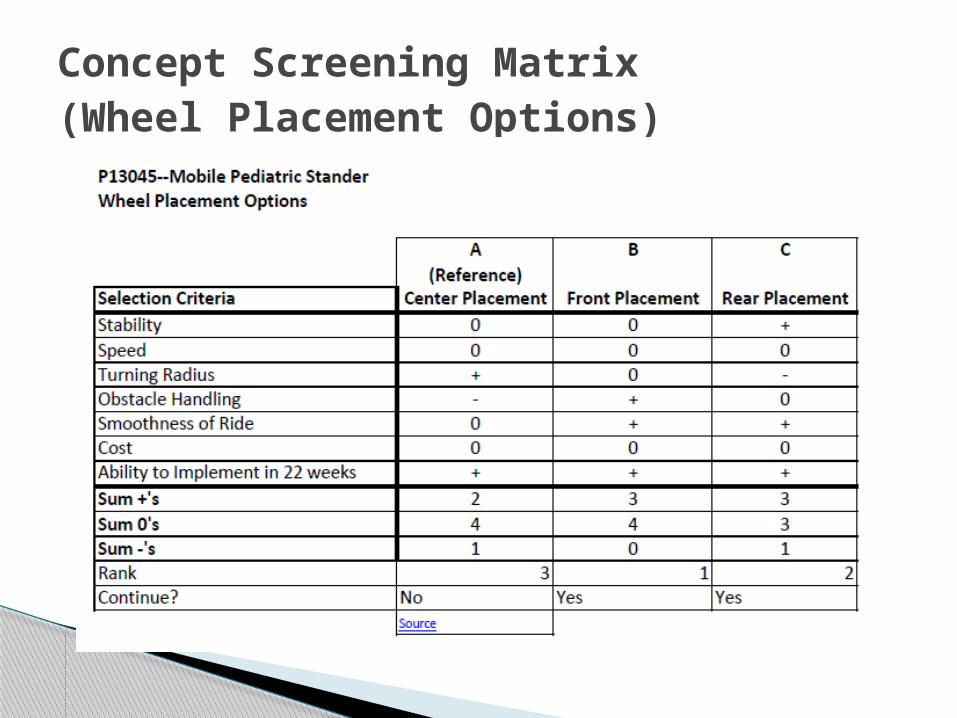
Concept Screening Matrix (Wheel Placement Options)

Concept Screening Matrix (Human Interface Devices)

Concept Screening Matrix (Raise/Lower System)
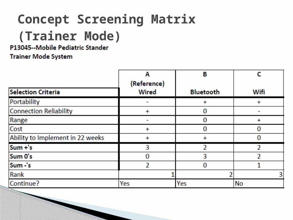
Concept Screening Matrix (Trainer Mode)
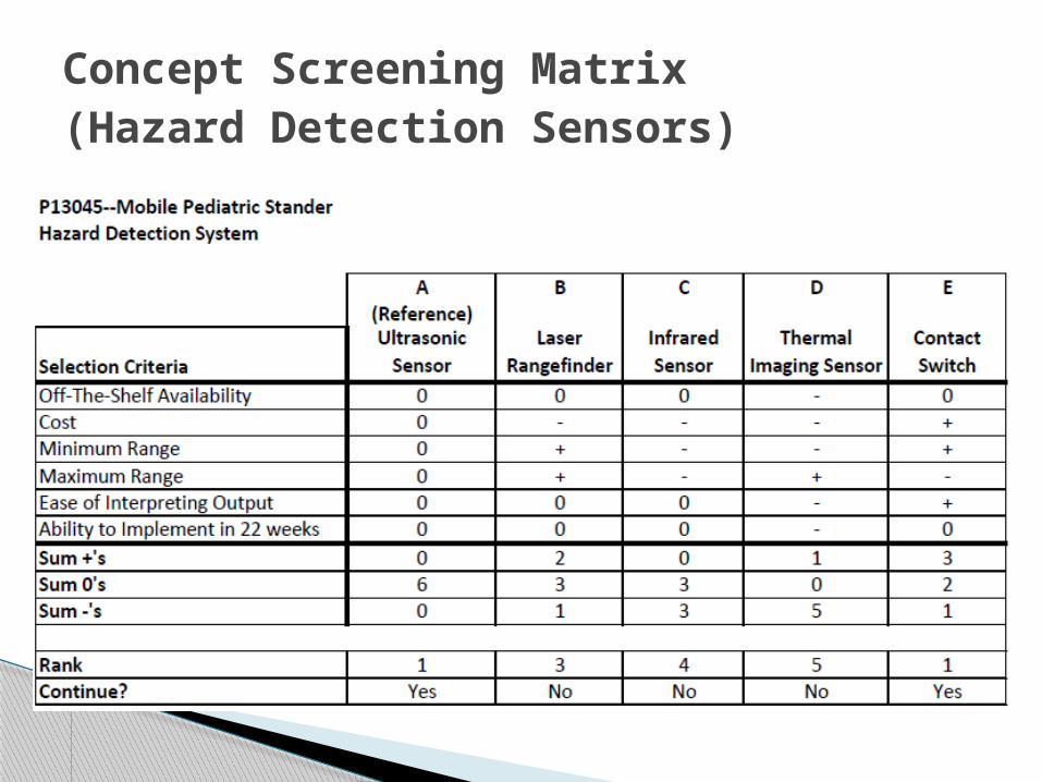
Concept Screening Matrix (Hazard Detection Sensors)

We wanted to find a happy medium between a stopping distance and a stopping time.
Luckily, we figured out that even at a speed of 6 mph stopping in 250 mm, we were safe from an acceleration perspective.
According to the International Association of Amusement Parks and Attractions, sneezing subjects the body to approx. 2.5g's, or 22.5 m/s^2, noticeably more than our top speed/shortest distance calculation.
Stopping Distances and Times
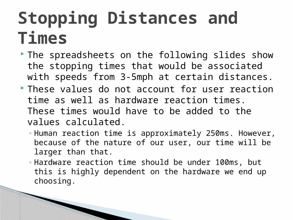
The spreadsheets on the following slides show the stopping times that would be associated with speeds from 3-5mph at certain distances.
These values do not account for user reaction time as well as hardware reaction times. These times would have to be added to the values calculated.◦ Human reaction time is approximately 250ms. However,
because of the nature of our user, our time will be larger than that.
◦ Hardware reaction time should be under 100ms, but this is highly dependent on the hardware we end up choosing.
Stopping Distances and Times

Stopping Distance: 1 meter
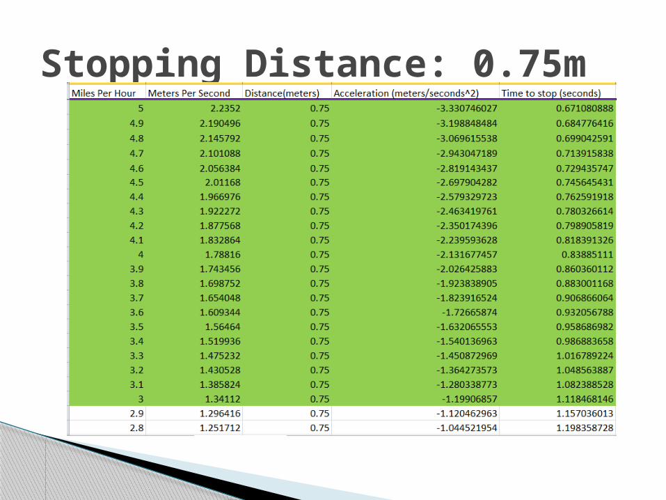
Stopping Distance: 0.75m
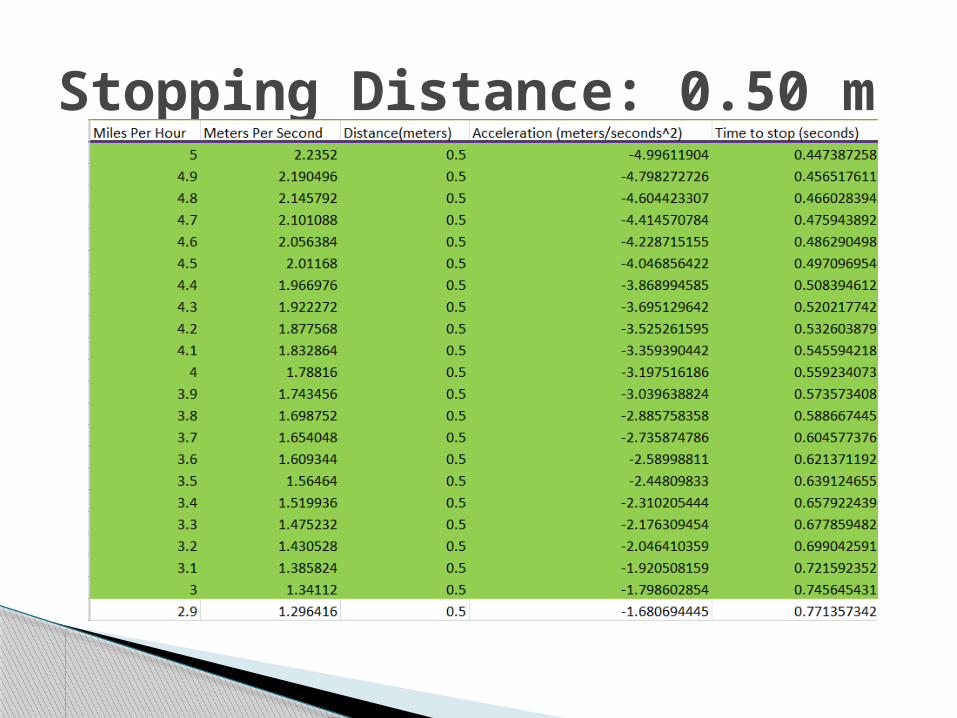
Stopping Distance: 0.50 m
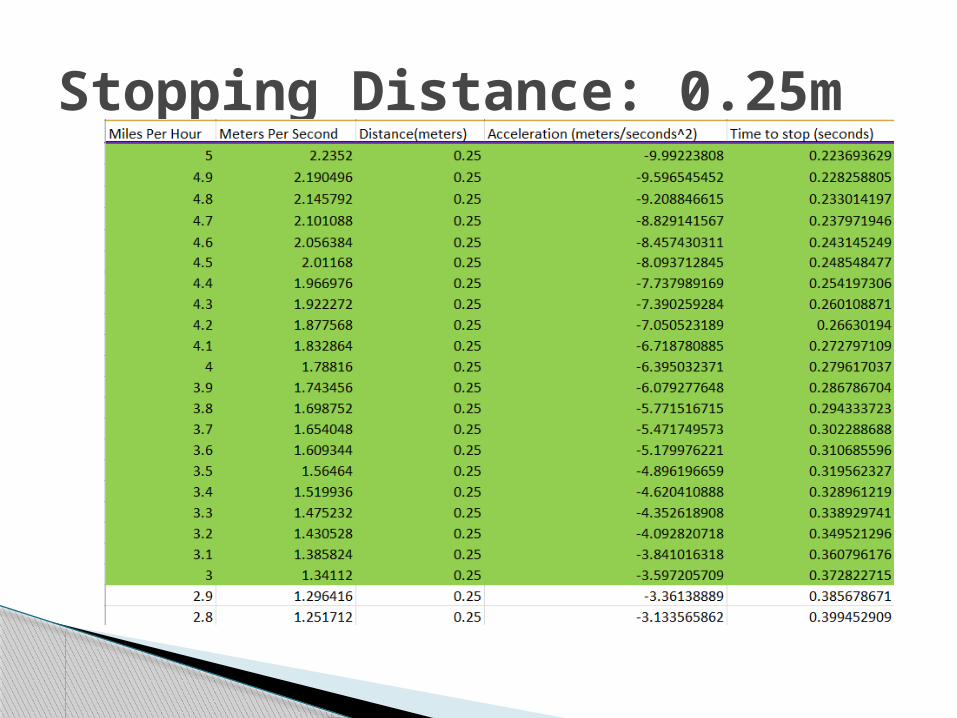
Stopping Distance: 0.25m
There are two options for speed control◦Our first option is potentiometers leading to the motors
◦Our second option is to set software limits to govern speed.
A Note on Speed Control
Feasibility Analysis (Tipping Force)
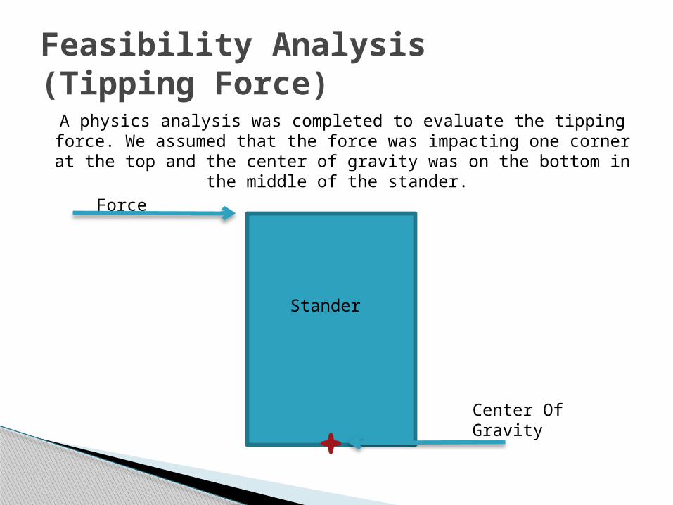
A physics analysis was completed to evaluate the tipping force. We assumed that the force was impacting one corner at the top and the
center of gravity was on the bottom in the middle of the stander.
Stander
Center Of Gravity
Force
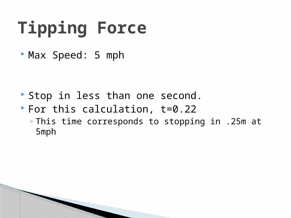
Max Speed: 5 mph
Stop in less than one second. For this calculation, t=0.22
◦ This time corresponds to stopping in .25m at 5mph
Tipping Force

Mass of Stander(Rabbit)=75kg Mass of User=40kg Total Mass=75+40=115kg
For the stander not to tip, the torque of the weight needs to be greater than or equal to
the torque of the applied force.
Tipping Force
This tells us that in a realistic case, our stander shouldn’t tip. Tipping Force
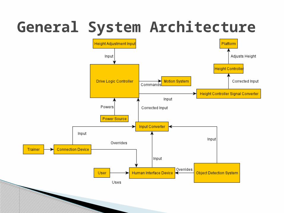
General System Architecture
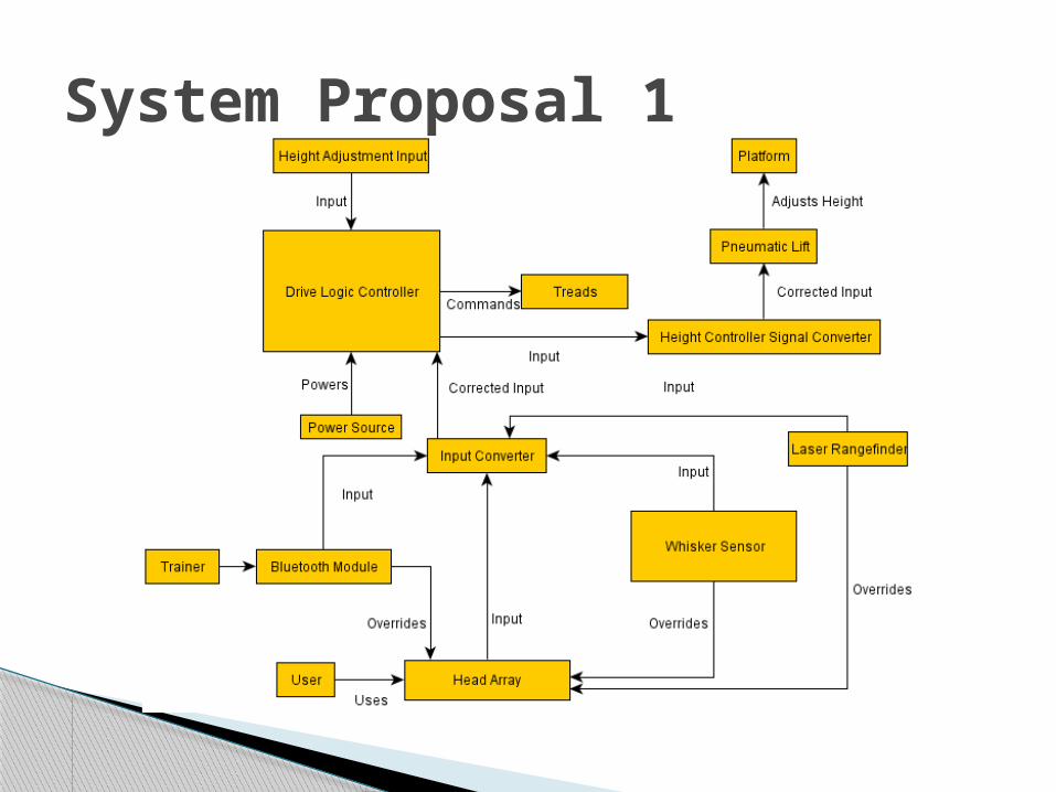
System Proposal 1
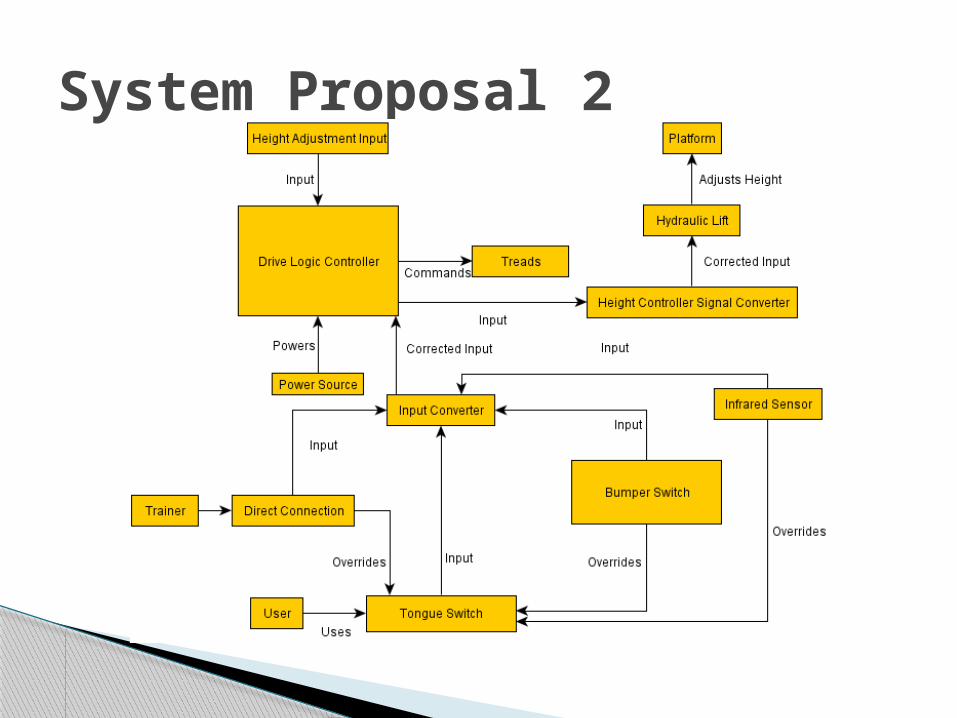
System Proposal 2
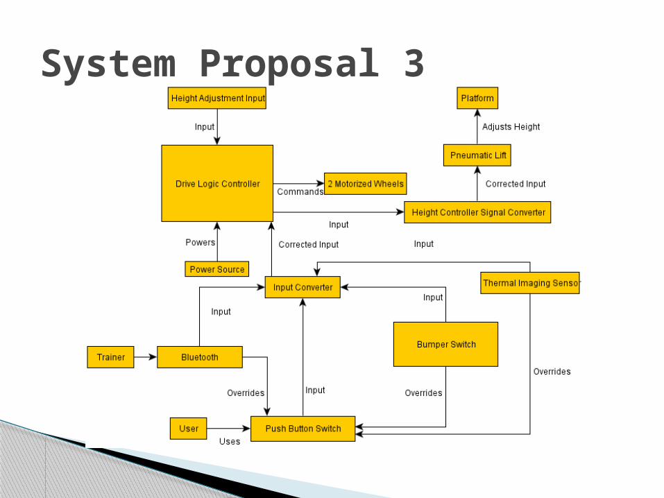
System Proposal 3
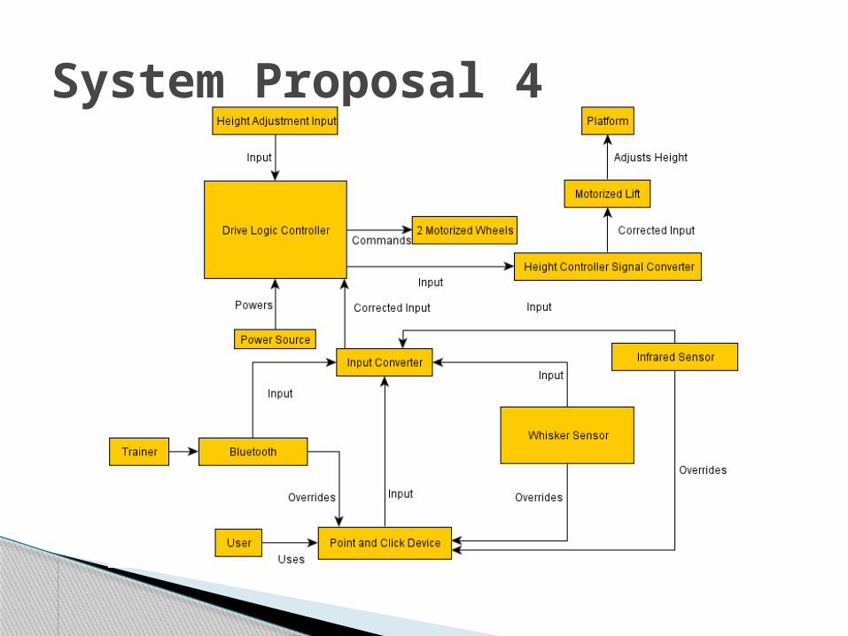
System Proposal 4
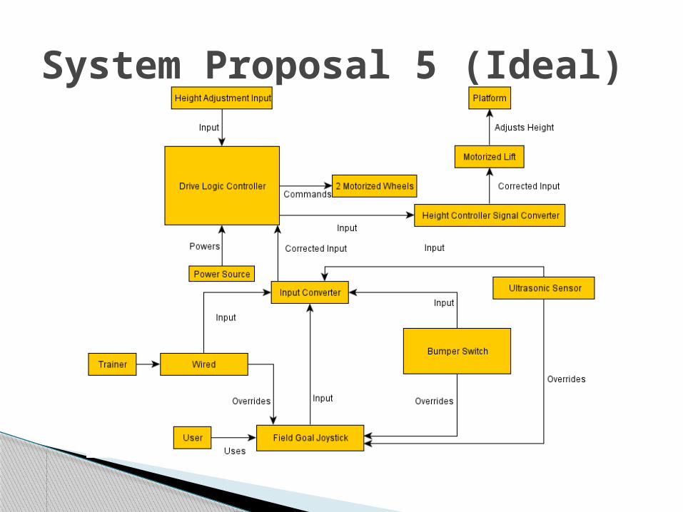
System Proposal 5 (Ideal)
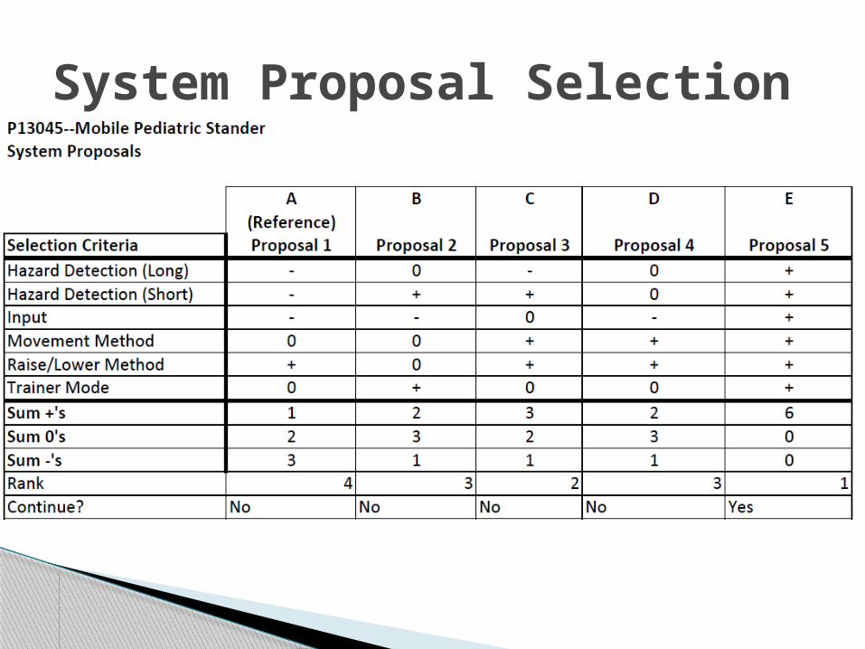
System Proposal Selection
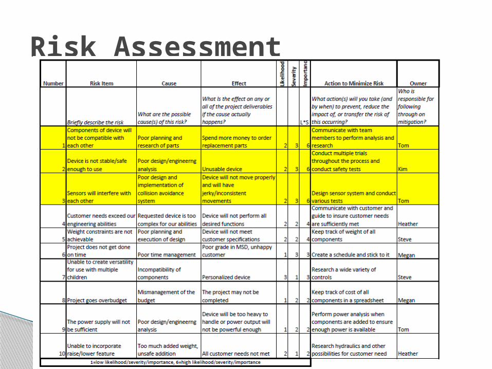
Risk Assessment
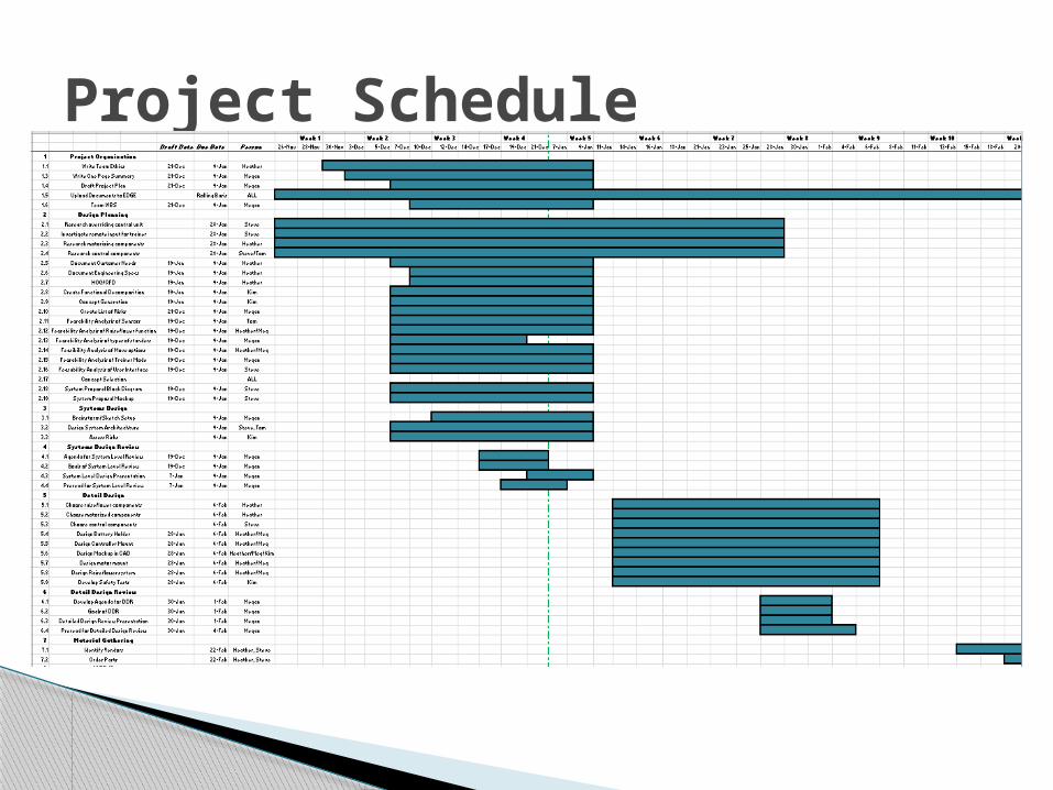
Project Schedule
Questions/Comments/Concerns