Heatcraft Refrigeration, General Systems Installation - Imperial
48
H-IM-64L September 2007 Part No. 25001201 Refrigeration Systems Installation and Operation Manual Replaces H-IM-64L (11/05) Table of Contents General Safety Information...............................................................................2 Inspection ...............................................................................................................2 Warranty Statement ............................................................................................2 Unit Cooler Placement .......................................................................................3 Unit Cooler Mounting .........................................................................................4 Defrost Thermostat ..............................................................................................5 Expansion Valves and Nozzles .....................................................................5-8 Condensate Drain Lines .....................................................................................9 Air Cooled Condensing Unit and Condenser Space and Location Requirements .......................................................................................... 10 Remote and Water Cooled Condensing Units Requirements ........... 11 Condensing Unit Rigging and Mounting ................................................. 12 Condensing Unit Accessories ................................................................ 13-17 Suction Filters, Driers, Sight Glasses ........................................................... 13 Demand Cooling ............................................................................................... 14 Head Pressure Control ..................................................................................... 15 Refrigerant Oils................................................................................................... 16 Phase Loss Monitor ........................................................................................... 17 Recommended Refrigerant Piping Practices .......................................... 17 Refrigeration Pipe Supports ......................................................................... 17 Suction Lines ....................................................................................................... 18 Suction Line Risers ............................................................................................ 18 Liquid Lines ......................................................................................................... 18 Hot Gas Defrost Systems .......................................................................... 19-20 Unit Cooler Piping ............................................................................................. 21 Line Sizing Charts ........................................................................................ 22-29 Weight of Refrigerants in Copper Lines During Operation ................ 30 City & Tower Water Connections.................................................................. 31 Evacuation and Leak Detection ................................................................... 31 Refrigerant Charging Instructions............................................................... 32 Field Wiring .......................................................................................................... 32 Check Out and Start Up .................................................................................. 32 Operational Check Out.................................................................................... 33 System Balancing - Compressor Superheat............................................. 33 Evaporator Superheat...................................................................................... 34 General Sequence of Operation .................................................................. 34 Electric Defrost Troubleshooting ................................................................. 35 Unit Cooler Troubleshooting Guide ........................................................... 36 System Troubleshooting Guide .................................................................... 37 Preventive Maintenance Guidelines..................................................... 38-39 InterLink Replacement Parts ......................................................................... 39 Typical Wiring Diagrams ........................................................................... 40-45 Service Record .................................................................................................... 46 H-IM-64L-0907 | Version 002
Transcript of Heatcraft Refrigeration, General Systems Installation - Imperial
H-IM-64L September2007 PartNo.25001201
RefrigerationSystems
InstallationandOperationManual
Replaces H-IM-64L (11/05)
TableofContentsGeneral Safety Information...............................................................................2Inspection ...............................................................................................................2Warranty Statement ............................................................................................2Unit Cooler Placement .......................................................................................3Unit Cooler Mounting .........................................................................................4Defrost Thermostat ..............................................................................................5Expansion Valves and Nozzles .....................................................................5-8Condensate Drain Lines .....................................................................................9Air Cooled Condensing Unit and Condenser Space and Location
Requirements .......................................................................................... 10Remote and Water Cooled Condensing Units Requirements ........... 11Condensing Unit Rigging and Mounting ................................................. 12Condensing Unit Accessories ................................................................13-17Suction Filters, Driers, Sight Glasses ........................................................... 13Demand Cooling ............................................................................................... 14Head Pressure Control ..................................................................................... 15Refrigerant Oils ................................................................................................... 16Phase Loss Monitor ........................................................................................... 17Recommended Refrigerant Piping Practices .......................................... 17Refrigeration Pipe Supports ......................................................................... 17Suction Lines ....................................................................................................... 18Suction Line Risers ............................................................................................ 18Liquid Lines ......................................................................................................... 18Hot Gas Defrost Systems ..........................................................................19-20Unit Cooler Piping ............................................................................................. 21Line Sizing Charts ........................................................................................22-29Weight of Refrigerants in Copper Lines During Operation ................ 30City & Tower Water Connections .................................................................. 31Evacuation and Leak Detection ................................................................... 31Refrigerant Charging Instructions ............................................................... 32Field Wiring .......................................................................................................... 32Check Out and Start Up .................................................................................. 32Operational Check Out .................................................................................... 33System Balancing - Compressor Superheat ............................................. 33Evaporator Superheat ...................................................................................... 34General Sequence of Operation .................................................................. 34Electric Defrost Troubleshooting ................................................................. 35Unit Cooler Troubleshooting Guide ........................................................... 36System Troubleshooting Guide .................................................................... 37Preventive Maintenance Guidelines .....................................................38-39InterLink Replacement Parts ......................................................................... 39Typical Wiring Diagrams ...........................................................................40-45Service Record .................................................................................................... 46
H-IM-64L-0907 | Version 002
2
GeneralSafetyInformation1. Installation and maintenance to be performed only by qualified personnel who are familiar with this type of equipment.
2. Some units are pressurized with dry air or inert gas. All units must be evacuated before charging the system with refrigerant.
3. Make sure that all field wiring conforms to the requirements of the equipment and all applicable national and local codes.
4. Avoid contact with sharp edges and coil surfaces. They are a potential injury hazard.
5. Make sure all power sources are disconnected before any service work is done on units.
WARNING: Refrigerant can be harmful if it is inhaled. Refrigerant must be used and recovered responsibly. Failuretofollowthiswarningmayresultinpersonalinjuryordeath.
InspectionResponsibility should be assigned to a dependable individual at the job site to receive material. Each shipment should be carefully checked against the bill of lading. The shipping receipt should not be signed until all items listed on the bill of lading have been accounted. Check carefully for concealed damage. Any shortage or damages should be reported to the delivering carrier. Damaged material becomes the delivering carrier’s responsibility, and should not be returned to the manufacturer unless prior approval is given to do so. When uncrating, care should be taken to prevent damage. Heavy equipment should be left on its shipping base until it has been moved to the final location. Check the serial tag information with invoice. Report any discrepancies to your Heatcraft Refrigeration Products Sales Representative.
WarrantyStatementSeller warrants to its direct purchasers that products, including Service Parts, manufactured by SELLER shall be of a merchantable quality, free of defects in material or workmanship, under normal use and service for a period of one (1)yearfromdateoforiginal installation,oreighteen(18)monthsfromdateofshipment by SELLER, whichever first occurs. Any product covered by this order found to Seller’s satisfaction to be defective upon examination at Seller’s factory will at SELLER’s option, be repaired or replaced and returned to Buyer via lowest common carrier, or SELLER may at its option grant Buyer a credit for the purchase price of the defective article. Upon return of a defective product to SELLER’s plant, freight prepaid, by Buyer, correction of such defect by repair or replacement, and return freight via lowest common carrier, shall constitute full performance by SELLER of its obligations hereunder.
SELLER shall have no liability for expenses incurred for repairs made by Buyer except by prior, written authorization. Every claim on account of breach of warranty shall be made to SELLER in writing within the warranty period specified above – otherwise such claim shall be deemed waived. Seller shall have no warranty obligation whatsoever if its products have been subjected to alteration, misuse, negligence, free chemicals in system, corrosive atmosphere, accident, or if operation is contrary to SELLER’s or manufacturer’s recommendations, or if the serial number has been altered, defaced, or removed.
MOTORCOMPRESSORS:Motor compressors furnished by SELLER are subject to the standard warranty terms set forth above, except that motor compressor replacements or exchanges shall be made through the nearest authorized wholesaler of the motor compressor manufacturer (not at SELLER’s factory) and no freight shall be allowed for transportation of the motor compressor to and from the wholesaler. The replacement motor compressor shall be identical to the model of the motor compressor being replaced. Additional charges which may be incurred throughout the substitution of other than identical replacements are not covered by this warranty. An optional, non assignable, four (4) year extended compressor warranty may be purchased within the boundaries of the United Sates of America, its territories and possessions, and Canada. With this extended compressor warranty, replacements are administered by an authorized compressor distributor only. Replacements within the first year of the warranty
area available through the distributor; the second through fifth years, the purchaser must submit a proof-of-purchase of a compressor and supply it to Heatcraft Refrigeration Products Warranty Claims for reimbursement.
Seller makes no express warranties except as noted above. All implied warranties are limited to the duration of the Express Warranty. Liability for incidental and consequential damages is excluded.
The forgoing is in lieu of all other warranties, express or implied, notwithstanding the provisions of the uniform commercial code, the Magnuson-Moss Warranty - Federal Trade Commission Improvement Act, or any other statutory or common law, federal or state.
SELLER makes no warranty, express or implied, of fitness for any particular purpose, or of any nature whatsoever, with respect to products manufactures or sold by seller hereunder, except as specifically set forth above and on the face hereof. It is expressly understood and agreed that SELLER shall not be liable to buyer, or any customer of buyer, for direct or indirect, special, incidental, consequential or penal damages, or for any expenses incurred by reason of the use or misuse by buyer or third parties of said products. To the extent said products may be considered "consumer products," As defined in Sec. 101 of the Magnuson-Moss Warranty - Federal Trade Commission Improvement Act, SELLER makes no warranty of any kind, express or implied, to "consumers," except as specifically set forth above and on the face hereof.
The following conditions should be adhered to when installing this unit to maintain the manufacturers warranty:
(a) System piping must be in accordance with good refrigeration practices. (b) Inertgasmustbechargedintothepipingduring
brazing. (c) The power supply to the unit must meet the
following conditions: A. Three phase voltages must be +/- 10% of nameplate ratings. Single phase must be within +10% or -5% of nameplate ratings. B. Phase imbalance cannot exceed 2%.(d) All control and safety switch circuits must be
properly connected according to the wiring diagram. (e) The factory installed wiring must not be changed
without written factory approval.(f ) All equipment is installed in accordance with
Heatcraft Refrigeration Products specified minimum clearances.
© 2007, Heatcraft Refrigeration Products LLC

�
One evaporator
Figure2.LowProfileUnitCoolers
UnitCoolers
RecommendedUnitCoolerPlacementSome general rules for evaporator placement which must be followed are:
1. The air pattern must cover the entire room.2. NEVER locate evaporators over doors.3. Location of aisles, racks, etc. must be known.4. Location relative to compressors for minimum
pipe runs.5. Location of condensate drains for minimum run.
The size and shape of the storage will generally determine the type and number of evaporators to be used and their location. The following are some typical examples:
Figure�.CenterMountUnitCoolers
One evaporator
MinimumUnitClearances
Figure1.MediumProfileandLargeUnitCoolers
NOTE: W = Total width of evaporator coil surface.
Two evaporators
Two evaporators
RecommendedMaximum-MinimumDimensionsforCenterMountUnitCoolerInstallations.
E S M T Max. Min. Max. Min. Max. Min. Max. Min. 25' 2' 20' 3' 40' 3' 40' 6'
NOTE: Leavespaceequaltounitheightbetweenbottomofunitandproduct.Donotstackproductinfrontoffans.
NOTE:H = Total height evaporator coil surface.
© 2007, Heatcraft Refrigeration Products LLC
4
the unit and the ceiling for cleaning. To comply with NSF Standard 7, the area above the unit cooler must be sealed or exposed in such a way to facilitate hand cleaning without the use of tools. When lagging or bolting the unit flush to the ceiling, seal the joint between the top and the ceiling with an NSF listed sealant and ends of open hanger channels must be sealed to prevent accumulation of foreign matter.
When locating unit coolers in a cooler or freezer, refer to Figures 1 through 4 for guidelines.
UnitCoolerMounting
Most evaporators can be mounted with rod hangers, lag screws, or bolts. Use 5/16" bolt and washers or rod for up to 250 pounds, 3/8" for up to 600 pounds and 5/8" for over 600 pounds. Care should be taken to mount the units level so that condensate drains properly. Note that some unit cooler designs achieve drain pan slope by using different height mounting brackets. In this situation, the top of the mounting brackets should be level. Adequate support must be provided to hold the weight of the unit.
When using rod hangers, allow adequate space between the top of
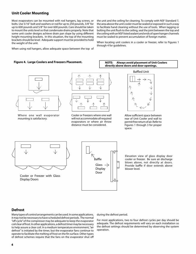
Figure4.LargeCoolersandFreezersPlacement.
Where one wall evaporator mounting is satisfactory.
Elevation view of glass display door cooler or freezer. Be sure air discharge blows above, not directly at doors. Provide baffle if door extends above blower level.
Baffled Unit
Cooler or Freezer with Glass Display Doors
GlassDisplayDoor
Baffle
NOTE: AlwaysavoidplacementofUnitCoolersdirectlyabovedoorsanddooropenings.
DefrostMany types of control arrangements can be used. In some applications, it may not be necessary to have scheduled defrost periods. The normal “off cycle” of the compressor may be adequate to keep the evaporator coil clear of frost. In other applications, a defrost timer may be necessary to help assure a clear coil. In a medium temperature environment, “air defrost” is initiated by the timer, but the evaporator fans continue to operate to facilitate the melting of frost on the fin surface. Other types of defrost schemes require that the fans on the evaporator shut off
during the defrost period.
For most applications, two to four defrost cycles per day should be adequate. The defrost requirements will vary on each installation so the defrost settings should be determined by observing the system operation.
Cooler or Freezers where one wall will not accommodate all required evaporators or where air throw distance must be considered.
Allow sufficient space between rear of Unit Cooler and wall to permit free return of air. Refer to Figures 1 through 3 for proper space.
5
DefrostThermostat
Adjustable(F25-209Series)The defrost duration is determined by the setting of the defrost termination thermostat. Initially, the thermostat should be set at mid-range. This will terminate the defrost at about a 60°F bulb temperature which will be satisfactory for most applications. A somewhat longer or shorter defrost can be obtained by adjusting the control clockwise for a shorter defrost and counterclockwise for a longer defrost. The fan delay temperature setting of the thermostat is factory set at 25°F. It can be adjusted upward by turning the adjusting screw next to the duration adjustment with a small screwdriver. Each complete clockwise rotation of this screw raises the setting approximately 3°F. This screw should not be adjusted more than four turns. Making this adjustment also raises the defrost termination temperature setting of the thermostat by a similar amount. For example, with the duration setting at mid-range, the termination temperature would be approximately 60°F. Turning the adjusting screw one turn would raise the fan delay temperature to about 28°F as well as changing the termination temperature from 60°F to 63°F. On medium temperature applications it may be necessary to raise the setting to assure that the thermostat will reset after a defrost.
Adjustable(060-100-00Series)This control has an adjustable defrost termination setpoint and an adjustable differential for controlling the fan delay. A typical termination setting is 60°F with a 25°F differential. Termination setting may be adjusted to increase/decrease the length of defrost. The differential should be adjusted to turn on the fans at 30 to 35°F (Fan Temperature = Termination Temperature – Differential). Actual coil temperature will be 5 to 10°F below this value. Some unit coolers are preset and labeled at the factory with special settings.
BimetalDiscA bimetal disc type thermostat is wired to the control circuit to terminate the defrost cycle when the coil temperature reaches approximately 55°F. The bimetal disc thermostat provides a fan delay to allow moisture on the coil to freeze after defrost termination.
Note: Onsystemswherethesuctiontemperatureisaboveapproximately25°F,thefansmaynotstartforanextendedperiodoftime.
On freezer applications, it may be necessary to apply a jumper to the fan delay on a warm box. This can be corrected by jumping the fan switch contacts. This will allow the fans to start immediately after defrost termination. This will disable the fan delay.
If moisture blow-off is encountered without the fan delay, a higher temperature defrost thermostat can be ordered. This thermostat terminates defrost at 60°F and prevents the fans from running when the coil temperature is above 40°F. Refer to the replacement parts list for the correct number to order.
Note: Defrostcontrolsarepositionedasdeterminedbyengineeringtest.Jobconditionsmayrequirethesensingdevicetoberelocatedforoptimaldefrosting.
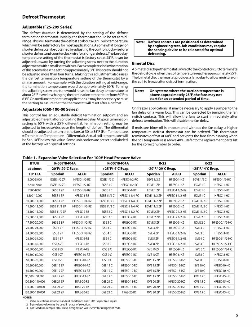
Table1.ExpansionValveSelectionFor100#HeadPressureValve BTUHR-507/R404AR-507/R404AR-22 R-22 atabout-20˚F/-29˚CEvap.+25˚F/-4˚CEvap. -20˚F/-29˚CEvap. +25˚F/-4˚CEvap. 10°T.D. Sporlan ALCO Sporlan ALCO Sporlan ALCO Sporlan ALCO 3,000-5,000 EGSE 1/2 ZP HFESC-1/2-RZ EGSE 1/2 C HFESC-1/2-RC EGVE 1/2 Z HFESC-1-HZ EGVE 1/2 C HFESC-1/2-HC
5,500-7000 EGSE 1/2 ZP HFESC-1/2-RZ EGSE 1 C HFESC-1/2-RC EGVE 1 ZP HFESC-1-HZ EGVE 1 C HFESC-1-HC
7500-8000 EGSE 1 ZP HFESC-1/2-RZ EGSE 1 C HFESC-1-RC EGVE 1 ZP HFESC-1 1/2-HZ EGVE 1 C HFESC-1-HC
8500-10,000 EGSE 1 ZP HFESC-1-RZ EGSE 11/2 C HFESC-1 1/4-RC EGVE 11/2 ZP HFESC-1 1/2-HZ EGVE 1 C HFESC-1-HC
10,500-11,000 EGSE 1 ZP HFESC-1 1/4-RZ EGSE 11/2 C HFESC-1 1/4-RC EGVE 11/2 ZP HFESC-2-HZ EGVE 11/2 C HFESC-1-HC
11,500-13,000 EGSE 11/2 ZP HFESC-1 1/2-RZ EGSE 11/2 C HFESC-1 1/4-RC EGVE 11/2 ZP HFESC-2-HZ EGVE 11/2 C HFESC-1-HC
13,500-15,000 EGSE 11/2 ZP HFESC-2-RZ EGSE 2 C HFESC-1 1/2-RC EGVE 2 ZP HFESC-2 1/2-HZ EGVE 11/2 C HFESC-2-HC
15,500-17,000 EGSE 2 ZP HFESC-2-RZ EGSE 2 C HFESC-2-RC EGVE 2 ZP HFESC-2 1/2-HZ EGVE 2 C HFESC-2-HC
17,500-20,000 EGSE 2 ZP HFESC-3 1/2-RZ SSE 3 C HFESC-2-RC EGVE 3 ZP HFESC-3-HZ EGVE 2 C HFESC-2 1/2-HC
20,500-24,000 SSE 3 ZP HFESC-3 1/2-RZ SSE 3 C HFESC-3-RC SVE 3 ZP HFESC-3-HZ SVE 3 C HFESC-3-HC
24,500-28,000 SSE 3 ZP HFESC-3 1/2-RZ SSE 4 C HFESC-3-RC SVE 4 ZP HFESC-5 1/2-HZ SVE 3 C HFESC-3-HC
28,500-34,000 SSE 4 ZP HFESC-5-RZ SSE 4 C HFESC-3-RC SVE 5 ZP HFESC-5 1/2-HZ SVE 4 C HFESC-5 1/2-HC
34,500-40,000 OSE 6 ZP HFESC-5-RZ SSE 6 C HFESC-5-RC SVE 8 ZP HFESC-5 1/2-HZ SVE 4 C HFESC-5 1/2-HC
40,500-50,000 OSE 8 ZP HFESC-7-RZ OSE 8 C HFESC-5-RC SVE 10 ZP HFESC-8-HZ SVE 5 C HFESC-5 1/2-HC
50,500-60,000 OSE 9 ZP HFESC-10-RZ OSE 9 C HFESC-7-RC SVE 10 ZP HFESC-8-HZ SVE 8 C HFESC-8-HC
60,500-70,000 OSE 9 ZP HFESC-10-RZ OSE 9 C HFESC-10-RC OVE 15 ZP HFESC-10-HZ SVE 8 C HFESC-8-HC
70,500-80,000 OSE 12 ZP HFESC-10-RZ OSE 12 C HFESC-10-RC OVE 15 ZP HFESC-15-HZ SVE 10 C HFESC-10-HC
80,500-90,000 OSE 12 ZP HFESC-13-RZ OSE 12 C HFESC-10-RC OVE 15 ZP HFESC-15-HZ SVE 10 C HFESC-10-HC
90,500-100,000 OSE 12 ZP HFESC-13-RZ OSE 12 C HFESC-13-RC OVE 15 ZP HFESC-15-HZ OVE 15 C HFESC-15-HC
100,500-110,000 OSE 21 ZP TRAE-20-RZ OSE 21 C HFESC-13-RC OVE 20 ZP HFESC-20-HZ OVE 15 C HFESC-15-HC
110,500-120,000 OSE 21 ZP TRAE-20-RZ OSE 21 C HFESC-13-RC OVE 20 ZP HFESC-20-HZ OVE 15 C HFESC-15-HC
120,500-130,000 OSE 21 ZP TRAE-20-RZ OSE 21 C TRAE-20-RC OVE 20 ZP HFESC-20-HZ OVE 15 C HFESC-15-HC
NOTES: 1. Valve selections assume standard conditions and 100°F vapor-free liquid. 2. Equivalent valve may be used in place of selection. 3. For "Medium Temp R-507," valve designation will use “P” for refrigerant code.

6
Figure5.BulbandContactLocation
Figure6.MultipleEvaporators
Table2.ExpansionValveSelection180#HeadPressureValve BTUHR-507/R404AR-507/R404A R-22 R-22 atabout-20˚F/-29˚CEvap.+25˚F/-4˚CEvap.-20˚F/-29˚CEvap.+25˚F/-4˚CEvap. 10˚T.D. Sporlan ALCO Sporlan ALCO Sporlan ALCO Sporlan ALCO 3,000-5,000 EGSE 1/2 ZP HFESC-1/2-RZ EGSE 1/2 C HFESC-1/2-RC EGVE 1/2 ZP HFESC-1/2-HZ EGVE 1/2 C HFESC-1/2-HC
5,500-7000 EGSE 1/2 ZP HFESC-1-RZ EGSE 1 C HFESC-1/2-RC EGVE 1 ZP HFESC-1-HZ EGVE 1/2 C HFESC-1-HC
7500-8000 EGSE 1 ZP HFESC-1-RZ EGSE 1 C HFESC-1/2-RC EGVE 1 ZP HFESC-1-HZ EGVE 1 C HFESC-1-HC
8500-10,000 EGSE 1 ZP HFESC-1-RZ EGSE 1 C HFESC-1-RC EGVE11/2 ZP HFESC-1 1/2-HZ EGVE 1 C HFESC-1-HC
10,500-11,000 EGSE 1 ZP HFESC-1 1/4-RZ EGSE 11/2 C HFESC-1-RC EGVE 11/2 ZP HFESC-1 1/2-HZ EGVE 1 C HFESC-1-HC
11,500-13,000 EGSE 1 1/2 ZP HFESC-1 1/4-RZ EGSE 11/2 C HFESC-1 1/4-RC EGVE 11/2 ZP HFESC-2-HZ EGVE 1 C HFESC-1 1/2-HC
13,500-15,000 EGSE 2 ZP HFESC-1 1/2-RZ EGSE 11/2 C HFESC-1 1/4-RC EGVE 2 ZP HFESC-2-HZ EGVE 11/2 C HFESC-1 1/2-HC
15,500-17,000 EGSE 2 ZP HFESC-2-RZ EGSE 2 C HFESC-1 1/2-RC EGVE 2 ZP HFESC-2 1/2-HZ EGVE 11/2 C HFESC-1 1/2-HC
17,500-20,000 EGSE 2 ZP HFESC-2-RZ EGSE 2 C HFESC-1 1/2-RC EGVE 3 ZP HFESC-2 1/2-HZ EGVE 11/2 C HFESC-2-HC
20,500-24,000 SSE 3 ZP HFESC-3-RZ SSE 3 C HFESC-2-RC SVE 3 ZP HFESC-3-HZ SVE 2 C HFESC-2-HC
24,500-28,000 SSE 4 ZP HFESC-3-RZ SSE 3 C HFESC-2-RC SVE 4 ZP HFESC-3-HZ SVE 3 C HFESC-2 1/2-HC
28,500-34,000 SSE 4 ZP HFESC-5-RZ SSE 4 C HFESC-3 1/2-RC SVE 4 ZP HFESC-5 1/2-HZ SVE 3 C HFESC-3-HC
34,500-40,000 SSE 6 ZP HFESC-5-RZ SSE 6 C HFESC-3 1/2-RC SVE 5 ZP HFESC-5 1/2-HZ SVE 3 C HFESC-3-HC
40,500-50,000 OSE 9 ZP HFESC-7-RZ SSE 6 C HFESC-3 1/2-RC SVE 8 ZP HFESC-5 1/2-HZ SVE 4 C HFESC-5 1/2-HC
50,500-60,000 OSE 9 ZP HFESC-7-RZ OSE 9 C HFESC-5-RC SVE 10 ZP HFESC-8-HZ SVE 5 C HFESC-5 1/2-HC
60,500-70,000 OSE 9 ZP HFESC-10-RZ OSE 9 C HFESC-7-RC OVE 15 ZP HFESC-8-HZ SVE 5 C HFESC-5 1/2-HC
70,500-80,000 OSE 12 ZP HFESC-10-RZ OSE 12 C HFESC-7-RC OVE 15 ZP HFESC-10-HZ SVE 8 C HFESC-8-HC
80,500-90,000 OSE 12 ZP HFESC-10-RZ OSE 12 C HFESC-10-RC OVE 15 ZP HFESC-10-HZ SVE 8 C HFESC-8-HC
90,500-100,000 OSE 12 ZP HFESC-13-RZ OSE 12 C HFESC-10-RC OVE 15 ZP HFESC-15-HZ SVE 10 C HFESC-8-HC
100,500-110,000 OSE 12 ZP HFESC-13-RZ OSE 12 C HFESC-10-RC OVE 20 ZP HFESC-15-HZ SVE 10 C HFESC-10-HC
110,500-120,000 OSE 12 ZP HFESC-13-RZ OSE 12 C HFESC-10-RC OVE 20 ZP HFESC-15-HZ SVE 10 C HFESC-10-HC
120,500-130,000 OSE 21 ZP HFESC-13-RZ OSE 12 C HFESC-13-RC OVE 20 ZP HFESC-15-HZ OVE 15 C HFESC-10-HC

7
DistributorNozzlesNozzles supplied with unit coolers are selected for numerous refrigerants at cataloged operating conditions and 95˚F liquid entering the expansion valve. If mechanical or another method of subcooling is used, the nozzle and expansion valve selection should be checked. For conditions outside those cataloged, use the charts to select a proper nozzle. Nozzle capacity should be within 135% to 180% of unit operating condition for optimum coil performance. Nozzles are available from Sporlan Wholesalers or from Heatcraft Refrigeration Products. A small nozzle can be drilled larger using the I.D. column in table 3, page 8. The hole must be accurately centered in the nozzle. A lathe is preferred for accurate drilling.
Expansion Valves and Distributor NozzlesBefore installing the expansion valve on the distributor of the evaporator, the proper distributor nozzle must be installed. Two nozzles are normally shipped with each evaporator for different refrigerants. Select the nozzle for the refrigerant that will be used. The size of the nozzles shipped with each evaporator is based on ordinary conditions, usually 95˚F liquid temperature and a maximum of 15˚F evaporator TD*. If a mechanical subcooler is to be used in your system, consult the factory or a representative for distributor nozzle sizing. This is very important as the nominal capacity of the nozzle increases as the liquid refrigerant temperature is lowered. If the correct size nozzle is not installed, poor refrigerant distribution
SelectingDistributorNozzleattheJobSiteYoumustknow4things:
1. Refrigerant2. Evaporating Temperature3. Tons or BTUH4. Highest Liquid Temperature
EXAMPLE: Select a nozzle for R22, 20˚F suction; 67,000 BTUH, 100˚F liquid entering TXV.
67,000
12,000
From Table 3 on page 8 select Size 4 rated at 3.84 tons. We prefer selecting at 135% - 180% of nominal rating. This is typically two sizes smaller than the closest tonnage in Table 3.
5.58
3.84
= 5.58 Tons
= 145% of Nominal Rating - okay.
= .78 Tons
may occur and poor evaporator operation may be experienced. For peak performance, it is important to select an expansion valve with the correct capacity and selective charge. Thermostatic expansion valves may be mounted in any position, but they should be installed as close to the evaporator as possible. For best performance, the outlet of the expansion valve should be installed directly to the distributor body. If this is not possible, the distance between the valve outlet and distributor should not exceed 24 inches. Elbows located between the expansion valve and distributor will hinder proper distribution and therefore, are not recommended. Some accessories may, however, necessitate the use of elbows.
Locate the expansion valve bulb on a horizontal length of suction line as close to the suction header as possible. The bulb should be clamped tightly on the suction line and insulated with a waterproof type of insulation. The bulb should never be placed on a coupling or other obstruction so as to not make 100 % contact with the suction line. The bulb should never be placed in a trap or downstream of a trap in a suction line. Locating the bulb on the bottom of a suction line is not recommended. The bulb should be installed at the 3, 4 or 8, 9 o’clock position on the suction line. See Figure 5 on page 6.
EXAMPLE: Select a nozzle for R404A, -20˚F suction; 9,400 BTUH, 60˚F liquid entering TXV.
9,400
12,000
0.78
1.83
From Table 3 on page 8 select Size 3/4 rated at 0.29 tons.
0.42
0.29
Typical selections would be between 135% and 180%.
[1.83 Factor for 60˚F Liquid]
= 145% of Nominal Rating - okay.
*Temperature Difference (design room temperature minus saturated suction temperature)
= .42 Corrected Tons
8
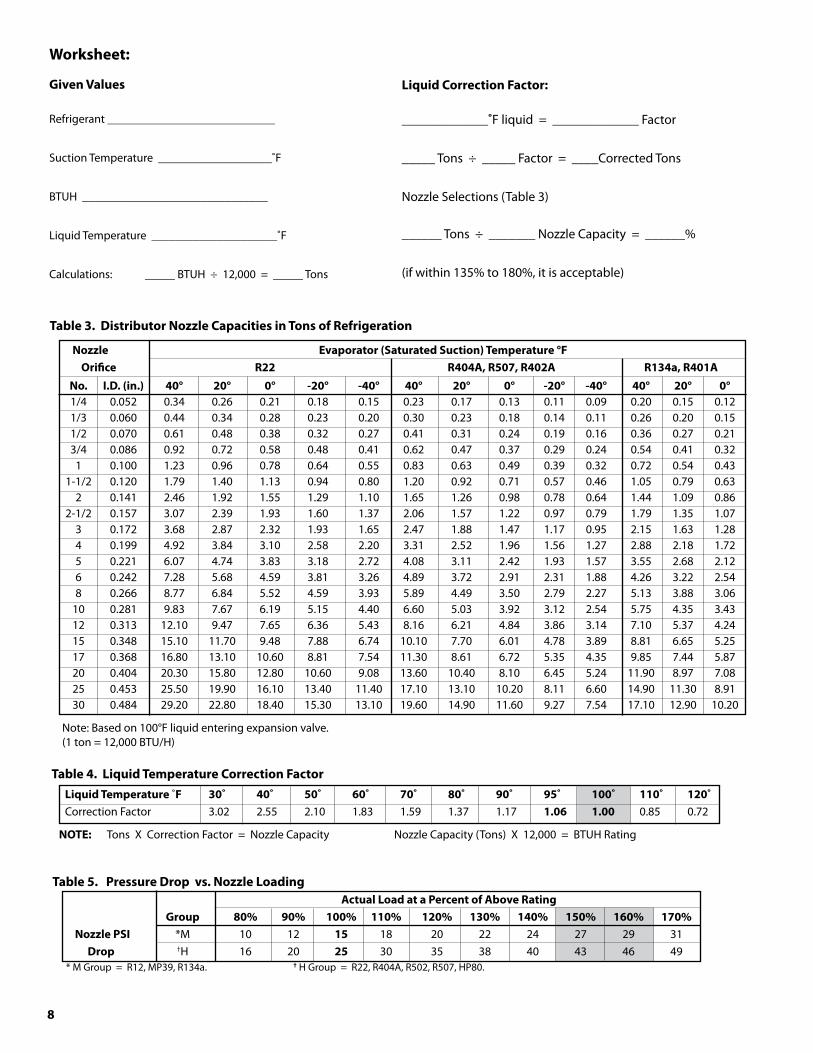
Worksheet:
GivenValues
Refrigerant ____________________________
Suction Temperature ___________________˚F
BTUH _______________________________
Liquid Temperature _____________________˚F
Calculations: _____ BTUH ÷ 12,000 = _____ Tons
LiquidCorrectionFactor:
_____________˚F liquid = _____________ Factor
_____ Tons ÷ _____ Factor = ____Corrected Tons
Nozzle Selections (Table 3)
______ Tons ÷ _______ Nozzle Capacity = ______%
(if within 135% to 180%, it is acceptable)
Table�.DistributorNozzleCapacitiesinTonsofRefrigeration
Nozzle Evaporator(SaturatedSuction)Temperature°F Orifice R22 R404A,R507,R402A R1�4a,R401A
Table4.LiquidTemperatureCorrectionFactor
ActualLoadataPercentofAboveRating Group 80% 90% 100% 110% 120% 1�0% 140% 150% 160% 170% NozzlePSI *M 10 12 15 18 20 22 24 27 29 31 Drop †H 16 20 25 30 35 38 40 43 46 49 * M Group = R12, MP39, R134a. † H Group = R22, R404A, R502, R507, HP80.
Note: Based on 100°F liquid entering expansion valve.(1 ton = 12,000 BTU/H)
LiquidTemperature˚F �0˚ 40˚ 50˚ 60˚ 70˚ 80˚ 90˚ 95˚ 100˚ 110˚ 120˚Correction Factor 3.02 2.55 2.10 1.83 1.59 1.37 1.17 1.06 1.00 0.85 0.72
NOTE: Tons X Correction Factor = Nozzle Capacity Nozzle Capacity (Tons) X 12,000 = BTUH Rating
No. I.D.(in.) 40° 20° 0° -20° -40° 40° 20° 0° -20° -40° 40° 20° 0° 1/4 0.052 0.34 0.26 0.21 0.18 0.15 0.23 0.17 0.13 0.11 0.09 0.20 0.15 0.12 1/3 0.060 0.44 0.34 0.28 0.23 0.20 0.30 0.23 0.18 0.14 0.11 0.26 0.20 0.15 1/2 0.070 0.61 0.48 0.38 0.32 0.27 0.41 0.31 0.24 0.19 0.16 0.36 0.27 0.21 3/4 0.086 0.92 0.72 0.58 0.48 0.41 0.62 0.47 0.37 0.29 0.24 0.54 0.41 0.32 1 0.100 1.23 0.96 0.78 0.64 0.55 0.83 0.63 0.49 0.39 0.32 0.72 0.54 0.43 1-1/2 0.120 1.79 1.40 1.13 0.94 0.80 1.20 0.92 0.71 0.57 0.46 1.05 0.79 0.63 2 0.141 2.46 1.92 1.55 1.29 1.10 1.65 1.26 0.98 0.78 0.64 1.44 1.09 0.86 2-1/2 0.157 3.07 2.39 1.93 1.60 1.37 2.06 1.57 1.22 0.97 0.79 1.79 1.35 1.07 3 0.172 3.68 2.87 2.32 1.93 1.65 2.47 1.88 1.47 1.17 0.95 2.15 1.63 1.28 4 0.199 4.92 3.84 3.10 2.58 2.20 3.31 2.52 1.96 1.56 1.27 2.88 2.18 1.72 5 0.221 6.07 4.74 3.83 3.18 2.72 4.08 3.11 2.42 1.93 1.57 3.55 2.68 2.12 6 0.242 7.28 5.68 4.59 3.81 3.26 4.89 3.72 2.91 2.31 1.88 4.26 3.22 2.54 8 0.266 8.77 6.84 5.52 4.59 3.93 5.89 4.49 3.50 2.79 2.27 5.13 3.88 3.06 10 0.281 9.83 7.67 6.19 5.15 4.40 6.60 5.03 3.92 3.12 2.54 5.75 4.35 3.43 12 0.313 12.10 9.47 7.65 6.36 5.43 8.16 6.21 4.84 3.86 3.14 7.10 5.37 4.24 15 0.348 15.10 11.70 9.48 7.88 6.74 10.10 7.70 6.01 4.78 3.89 8.81 6.65 5.25 17 0.368 16.80 13.10 10.60 8.81 7.54 11.30 8.61 6.72 5.35 4.35 9.85 7.44 5.87 20 0.404 20.30 15.80 12.80 10.60 9.08 13.60 10.40 8.10 6.45 5.24 11.90 8.97 7.08 25 0.453 25.50 19.90 16.10 13.40 11.40 17.10 13.10 10.20 8.11 6.60 14.90 11.30 8.91 30 0.484 29.20 22.80 18.40 15.30 13.10 19.60 14.90 11.60 9.27 7.54 17.10 12.90 10.20
Table5.PressureDropvs.NozzleLoading

9
WARNING: Allpowermustbedisconnectedbeforeclean-ing.Drainpanalsoservesascoverofhazardousmovingparts.Operationofunitwithoutdrainpanconstitutesahazard.
CondensateDrainLinesEither copper or steel drain lines should be used and properly protected from freezing. In running drain lines, provide a minimum 1/4 inch per foot pitch for proper drainage. Drain lines should be at least as large as the evaporator drain connection. All plumbing connections should be made in accordance with local plumbing codes. All condensate drain lines must be trapped, and run to an open drain. They must never be connected directly to the sewer system. Traps in the drain line must be located in a warm ambient. We recommend a trap on each evaporator drain line prior to any tee connections. Traps located outside, or extensive outside runs of drain line must be wrapped with a drain line heater. The heater should be connected so that it operates continuously. It is recommended that the drain line be insulated to prevent heat loss. A heat input of 20 watts per linear foot of drain line for 0˚F (-18˚C) room applications and 30 watts per linear foot for -20˚F (-29˚C) rooms is satisfactory. In freezers, the evaporator drain pan fitting should be included when heating and insulating the drain line.
Inspect drain pan periodically to insure free drainage of condensate. If drain pan contains standing water, check for proper installation. The drain pan should be cleaned regularly with warm soapy water.
Figure7.CondensateDrainLines
DRAIN LINE MIN.PITCH - 1/4”/ FT.
VAPOR SEAL
TRAP
OPEN DRAIN
NOTE: Alwaystrapsingleevaporatorsystemdrain linesindividuallytopreventhumiditymigration.
Traps on low temperature units must be outside of refrigerated enclosures. Traps subject to freezing temperatures must be wrapped with heat tape and insulated.
10
The most important consideration which must be taken into account when deciding upon the location of air-cooled equipment is the provision for a supply of ambient air to the condenser, and removal of heated air from the condensing unit or remote condenser area. Where this essential requirement is not adhered to, it will result in higher head pressures, which cause poor operation and potential failure of equipment. Units must not be located in the vicinity of steam, hot air or fume exhausts. Corrosive atmospheres require custom designed condensers.
Another consideration which must be taken is that the unit should be mounted away from noise sensitive spaces and must have adequate support to avoid vibration and noise transmission into the building. Units should be mounted over corridors, utility areas, rest rooms and other auxiliary areas where high levels of sound are not an important factor. Sound and structural consultants should be retained for recommendations.
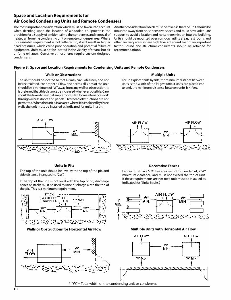
Figure8.SpaceandLocationRequirementsforCondensingUnitsandRemoteCondensers
UnitsinPitsThe top of the unit should be level with the top of the pit, and side distance increased to “2W”.
If the top of the unit is not level with the top of pit, discharge cones or stacks must be used to raise discharge air to the top of the pit. This is a minimum requirement.
DecorativeFencesFences must have 50% free area, with 1 foot undercut, a “W” minimum clearance, and must not exceed the top of unit. If these requirements are not met, unit must be installed as indicated for “Units in pits”.
WallsorObstructionsThe unit should be located so that air may circulate freely and not be recirculated. For proper air flow and access all sides of the unit should be a minimum of “W” away from any wall or obstruction. It is preferred that this distance be increased whenever possible. Care should be taken to see that ample room is left for maintenance work through access doors and panels. Overhead obstructions are not permitted. When the unit is in an area where it is enclosed by three walls the unit must be installed as indicated for units in a pit.
MultipleUnitsFor units placed side by side, the minimum distance between units is the width of the largest unit. If units are placed end to end, the minimum distance between units is 4 feet.
WallsorObstructionsforHorizontalAirFlow MultipleUnitswithHorizontalAirFlow
* “W” = Total width of the condensing unit or condenser.
SpaceandLocationRequirementsforAirCooledCondensingUnitsandRemoteCondensers

11
RequirementsforRemoteandWaterCooledCondensingUnitsGeneralInstallationThe indoor compressor units are designed to be used with a remote condenser. The water cooled units are similar, except that they have an integral water cooled condenser. Inlet and outlet water connections are to be made in the field. On units having a compressor water jacket, incoming water shall be routed through the jacket prior to entering the condenser. For cleaning purposes, condenser end plates can be removed to give access to the water tubes. Cleaning is accomplished by a simple spiral tool powered by an ordinary electric drill. During installation, allow space for cleaning the condenser. Commercial equipment of this type is intended for installation by qualified refrigeration mechanics.
TypicalArrangementsDiagram 1 illustrates a typical piping arrangement involving a remote condenser located at a higher elevation, as commonly encountered when the condenser is on a roof and the compressor and receiver are on grade level or in a basement equipment room.
In this case, the design of the discharge line is very critical. If properly sized for full load condition, the gas velocity might be too low at reduced loads to carry oil up through the discharge line and condenser coil. Reducing the discharge line size would increase the gas velocity sufficiently at reduced load conditions; however, when operating at full load, the line would be greatly undersized, and thereby creating an excessive refrigerant pressure drop. This condition can be overcome in one of two of the following ways:
1. The discharge line may be properly sized for the desired pressure drop at full load conditions and an oil separator installed at the bottom of the trap in the discharge line from the compressor.
2. A double riser discharge line may be used as shown in Diagram 2. Line “A” should be sized to carry the oil at minimum load conditions and the line “B” should be sized so that at the full load conditions both lines would have sufficient flow velocity to carry the oil to the condenser.
WaterRegulatingValveUsing this control on the water cooled condensing units, the head pressure can be maintained by adjusting the flow of water through the condenser section. This type control is most often located on the water entering side of the condenser and is regulated by the refrigerant condensing pressure.
SubcoolerDiagrams 1 and 2 below show typical subcooler piping. Diagram 1 is the preferred connection with receiver as it provides maximum subcooling. Diagram 2 may be used if the receiver is located far from the condenser.
Notes:1. All oil traps are to be as short in radius as possible. Common practice is to fabricate the trap using three 90 degree ells.
2. Pressure relief valves are recommended at the condenser for protection of the coil.
3. A pressure valve at the high point in the discharge line is recommended to aid in removing non-condensables.
4. The placement of a subcooler should be that it does not interfere with normal airflow of the condenser. Increased static of the unit could cause a decrease in system capacity and fan motor damage.
GPMRequirementsThe GPM Requirements table below can be used as a guide for determining water flow requirements of the condenser. Operation below the minimum flow rates may result in excessive fouling and poor heat transfer. Operation above the maximum flow rates risk premature impingement corrosion and tube failure.
WaterCooledCondenserGPMRequirements
* Low Temp. Rating Point: -20°F SST, 85°F EWT, 105°F CT, 5°F SC* Medium/High Temp. Rating Point: 25°F SST, 85°F EWT, 105°F CT, 5°F SC
Model MinGPM MaxGPM RatedGPM* SWN0075H2 0.7 5 1.25 SWN0075M2 0.7 5 1.5 SWN0090H2 0.7 5 2 SWN0090M6 0.7 5 2.25 SWN0100H2 0.7 5 2 SWN0150H2 0.7 5 2.5 SWN0150L6 0.7 5 1.5 SWN0199M6 0.7 5 4 SWN0200H2 2 18 4 SWN0200L6 2 18 2 SWN0200M2 2 18 5 SWN0200M6 2 18 7 SWN0210L6 2 18 3 SWN0310E6 4 18 5 SWN0300H2 4 18 6 SWN0310L6 4 18 4 SWN0310M6 4 18 9 SWN0311L6 4 18 6 SWN0400H2 4 18 11 SWN0400L6 4 18 7 SWN0499H2 7.5 23 10 SWN0500H2 7.5 23 12.5 SWN0500M6 7.5 23 15 SWN0599L6 7.5 23 7.5 SWN0600L6 7.5 23 10 SWN0601L6 7.5 23 10 SWN0750H2 10 25 12.5 SWN0750L6 10 25 10 SWN0760H2 10 25 15 SWN0761H2 10 25 20 SWN0900L6 20 67 20 SWN1000H2 20 67 30 SWN1000L6 20 67 20 SWN1500H2 20 80 35 SWN1500L6 20 80 20 SWN2000H2 20 80 40 SWN2200L6 20 80 25
Diagram 1 Diagram 2
12
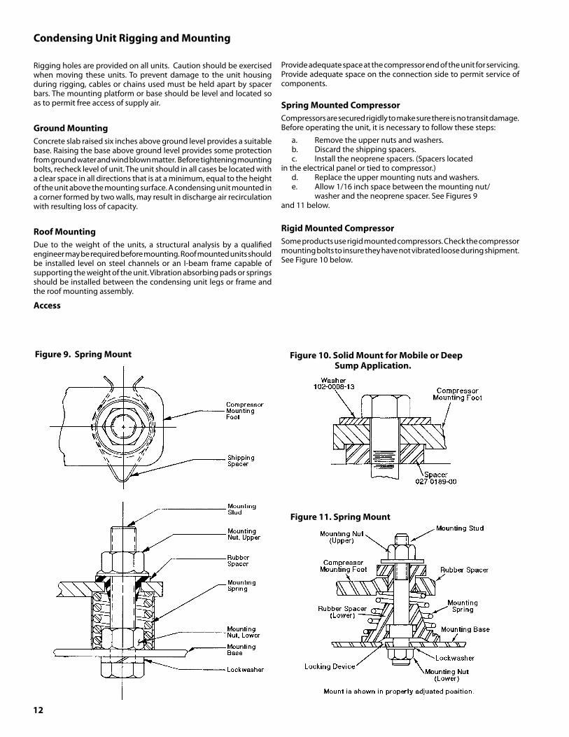
Figure9.SpringMount
Figure11.SpringMount
Figure10.SolidMountforMobileorDeep SumpApplication.
CondensingUnitRiggingandMounting
Rigging holes are provided on all units. Caution should be exercised when moving these units. To prevent damage to the unit housing during rigging, cables or chains used must be held apart by spacer bars. The mounting platform or base should be level and located so as to permit free access of supply air.
GroundMountingConcrete slab raised six inches above ground level provides a suitable base. Raising the base above ground level provides some protection from ground water and wind blown matter. Before tightening mounting bolts, recheck level of unit. The unit should in all cases be located with a clear space in all directions that is at a minimum, equal to the height of the unit above the mounting surface. A condensing unit mounted in a corner formed by two walls, may result in discharge air recirculation with resulting loss of capacity.
RoofMountingDue to the weight of the units, a structural analysis by a qualified engineer may be required before mounting. Roof mounted units should be installed level on steel channels or an I-beam frame capable of supporting the weight of the unit. Vibration absorbing pads or springs should be installed between the condensing unit legs or frame and the roof mounting assembly.
Access
Provide adequate space at the compressor end of the unit for servicing. Provide adequate space on the connection side to permit service of components.
SpringMountedCompressorCompressors are secured rigidly to make sure there is no transit damage. Before operating the unit, it is necessary to follow these steps:
a. Remove the upper nuts and washers.b. Discard the shipping spacers.c. Install the neoprene spacers. (Spacers located
in the electrical panel or tied to compressor.)d. Replace the upper mounting nuts and washers.e. Allow 1/16 inch space between the mounting nut/
washer and the neoprene spacer. See Figures 9 and 11 below.
RigidMountedCompressorSome products use rigid mounted compressors. Check the compressor mounting bolts to insure they have not vibrated loose during shipment. See Figure 10 below.
1�
SuctionFilters,Driers,SightGlassesThere are two types of suction and liquid filter/driers used on Heatcraft Refrigeration Products units. Replaceable core and/or sealed units are used, dependent upon the option package ordered.
Suction filters, regardless of type, are always installed upstream of the compressor suction service valve, and any accumulators or other options that may be installed. Suction filters are equipped with “Schrader” type access valves to allow field measurement of pressure drop across the device. This allows plugged filters and elements to be identified very quickly and easily so they can be replaced when the pressure drop is excessive. Refer to the specific manufacturers’ recommendation on servicing these units by make and model.
Liquid filter/driers, regardless of type, are always installed downstream of the receiver outlet service valve, and upstream of the liquid line solenoid valve (if supplied). Liquid line driers may or may not have an access valve, dependent on the size and application.
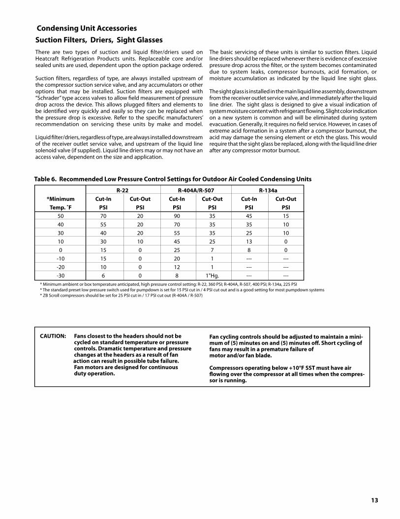
Table6.RecommendedLowPressureControlSettingsforOutdoorAirCooledCondensingUnits
R-22 R-404A/R-507 R-1�4a *Minimum Cut-In Cut-Out Cut-In Cut-Out Cut-In Cut-Out Temp.˚F PSI PSI PSI PSI PSI PSI 50 70 20 90 35 45 15 40 55 20 70 35 35 10 30 40 20 55 35 25 10 10 30 10 45 25 13 0 0 15 0 25 7 8 0 -10 15 0 20 1 --- --- -20 10 0 12 1 --- --- -30 6 0 8 1"Hg. --- --- * Minimum ambient or box temperature anticipated, high pressure control setting: R-22, 360 PSI; R-404A, R-507, 400 PSI; R-134a, 225 PSI * The standard preset low pressure switch used for pumpdown is set for 15 PSI cut in / 4 PSI cut out and is a good setting for most pumpdown systems * ZB Scroll compressors should be set for 25 PSI cut in / 17 PSI cut out (R-404A / R-507)
CAUTION: Fansclosesttotheheadersshouldnotbe cycledonstandardtemperatureorpressure controls.Dramatictemperatureandpressure changesattheheadersasaresultoffanactioncanresultinpossibletubefailure. Fanmotorsaredesignedforcontinuous dutyoperation.
Fancyclingcontrolsshouldbeadjustedtomaintainamini-mumof(5)minutesonand(5)minutesoff.Shortcyclingoffansmayresultinaprematurefailureofmotorand/orfanblade.
Compressorsoperatingbelow+10°FSSTmusthaveairflowingoverthecompressoratalltimeswhenthecompres-sorisrunning.
CondensingUnitAccessories
The basic servicing of these units is similar to suction filters. Liquid line driers should be replaced whenever there is evidence of excessive pressure drop across the filter, or the system becomes contaminated due to system leaks, compressor burnouts, acid formation, or moisture accumulation as indicated by the liquid line sight glass.
The sight glass is installed in the main liquid line assembly, downstream from the receiver outlet service valve, and immediately after the liquid line drier. The sight glass is designed to give a visual indication of system moisture content with refrigerant flowing. Slight color indication on a new system is common and will be eliminated during system evacuation. Generally, it requires no field service. However, in cases of extreme acid formation in a system after a compressor burnout, the acid may damage the sensing element or etch the glass. This would require that the sight glass be replaced, along with the liquid line drier after any compressor motor burnout.
14
Figure1�.SingleStageInternalRefrigerantInjectionFigure12.DemandCoolingInjection
Evaporating Temperature (ºF)
Con
dens
ing
Tem
pera
ture
(ºF)
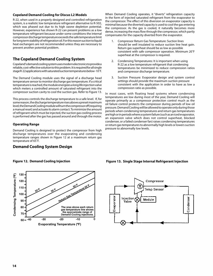
CopelandDemandCoolingforDiscusL2ModelsR-22, when used in a properly designed and controlled refrigeration system, is a realistic low temperature refrigerant alternative to R-502, which was phased out due to its high ozone depletion potential. However, experience has shown R-22 can present problems as a low temperature refrigerant because under some conditions the internal compressor discharge temperature exceeds the safe temperature limit for long term stability of refrigeration oil. For this reason suction to liquid heat exchangers are not recommended unless they are necessary to prevent another potential problem.
TheCopelandDemandCoolingSystemCopeland's demand cooling system uses modern electronics to provide a reliable, cost-effective solution to this problem. It is required for all single stage R-22 applications with saturated suction temperatures below -10˚F.
The Demand Cooling module uses the signal of a discharge head temperature sensor to monitor discharge gas temperature. If a critical temperature is reached, the module energizes a long life injection valve which meters a controlled amount of saturated refrigerant into the compressor suction cavity to cool the suction gas. Refer to Figure 13.
This process controls the discharge temperature to a safe level. If, for some reason, the discharge temperature rises above a preset maximum level, the Demand Cooling module will turn the compressor off (requiring a manual reset) and actuate its alarm contact. To minimize the amount of refrigerant which must be injected, the suction gas cooling process is performed after the gas has passed around and through the motor. OperatingRange
Demand Cooling is designed to protect the compressor from high discharge temperatures over the evaporating and condensing temperature ranges shown in Figure 12 at a maximum return gas temperature of 65˚F.
DemandCoolingSystemDesign
When Demand Cooling operates, it “diverts” refrigeration capacity in the form of injected saturated refrigerant from the evaporator to the compressor. The effect of this diversion on evaporator capacity is minimal because the diverted capacity is used to cool the gas entering the compressor. As the gas is cooled, it naturally becomes more dense, increasing the mass flow through the compressor, which partly compensates for the capacity diverted from the evaporator.
1. Compressor Return Gas Temperature: Suction lines should be well insulated to reduce suction line heat gain. Return gas superheat should be as low as possible consistent with safe compressor operation. Minimum 20˚F superheat at the compressor is required.
2. Condensing Temperatures: It is important when using R-22 as a low temperature refrigerant that condensing temperatures be minimized to reduce compression ratios and compressor discharge temperature.
3. Suction Pressure: Evaporator design and system control settings should provide the maximum suction pressure consistent with the application in order to have as low a compression ratio as possible.
In most cases, with floating head systems where condensing temperatures are low during most of the year, Demand Cooling will operate primarily as a compressor protection control much as the oil failure control protects the compressor during periods of low oil pressure. Demand Cooling will be allowed to operate only during those periods when condensing temperatures and return gas temperatures are high or in periods where a system failure (such as an iced evaporator, an expansion valve which does not control superheat, blocked condenser, or a failed condenser fan) raises condensing temperatures or return gas temperatures to abnormally high levels or lowers suction pressure to abnormally low levels.

15
Table7.AmbientFanCycleThermostatSettings
HeadPressureControlSeveral types of head pressure control systems are available on condensing units:
A. Dual Valve System. (See section on operation and adjustment.)
B. Single Valve system. No adjustments are necessary. (See section on operation.)
C. Ambient Fan Cycle Control. (See section on operation and adjustment.)
D. No Control.
A.DualValveSystem
The system employs an ORI (open on rise of inlet pressure) valve and an ORD ( open on rise of differential pressure) valve. The high pressure discharge gas is introduced above the liquid in the receiver tank. The receiver discharge is regulated by the ORI valve.
The discharge pressure of the ORI valve must be adjusted to regulate the unit for proper operating conditions. Adjust the ORI valve shown on the following diagram to maintain a discharge pressure of 160 to 180 PSIG.
B.SingleValveSystem
The standard valve used on high pressure refrigerant systems controls the head pressure at approximately 180 PSIG. There is no adjustment for this valve. On low pressure refrigerant systems the valve controls pressure at approximately 100 PSIG. For energy efficiency, the 100 PSIG valve is sometimes used on high pressure refrigerant systems. When this is done, refer to Table 1 on page 5 for expansion valve selections.
At condensing pressures above the valve setting, flow enters Port C and leaves Port R. When the condensing pressure falls below the valve setting, the valve modulates to permit discharge gas to enter Port D. Metering discharge gas into the refrigerant flow leaving the condenser produces a higher pressure at the condenser outlet, reduces the flow, and causes the level of liquid refrigerant to rise in the condenser. This “flooding” of the condenser with liquid refrigerant reduces the available condensing surface, holding the condensing pressure at the valve setting.
C.AmbientFanCycleControl
This is an automatic winter control method which will maintain a condensing pressure within reasonable limits by cycling fan motors in response to outside air temperature. The thermostat(s) should be field adjusted to shut off the fan when the condensing temperature is reduced to approximately 90˚F. Table 7 lists approximate settings for several system T.D.’s. These settings are approximate as they do not take into account variations in load.
Figure14.DualValvePipingArrangement
Figure15.SingleValveFloodingValvePipingArrangement
OperationandAdjustmentCondensing units with dual valves require sufficient charge to partially flood the condenser during low ambient conditions.
Valve adjustment should be made with gauges connected to the discharge port of the compressor. Adjustments should be made during mild or low ambient conditions. Turning the valve stem “clockwise” on the ORI valve will increase the discharge pressure, while turning the valve stem “counterclockwise” will decrease the discharge pressure.
If adjustments are made during warm ambient conditions, it may not be possible to adjust the regulator valve as low as desired. Readjustment may be necessary once cooler conditions prevail.
CAUTION: Undernocircumstanceshouldallcondenser motorsbeallowedtocycleoffononecontrol. Atleastonemotorshallbewiredtooperate atalltimes.Undermostcircumstances,the condensermotornearesttheinletheader shouldremainonwheneverthecompressor isoperating.
Design ThermostatSettings Models T.D. T1 T2 T� 30 60 2-fan units: 25 65 20 70 4-fan units: 15 75 30 60 40 3-fan units: 25 65 55 20 70 60 6-fan units: 15 75 65 30 60 50 30 8-fan units: 25 65 55 40 20 70 65 50 15 75 70 60NOTE: Cycle pairs of fans on double wide units.

16
MineralOilsThe BR and Scroll compressors use Sontex 200, a “white oil”. This oil is not suitable for low temperature applications nor is it available through the normal refrigeration wholesalers. For field “top-off” the use of 3GS or equivalent, or Zerol 200TD is permissible, as long as at least 50% of the total oil charge remains Sontex 200.
Suniso 3GS, Texaco WF32 and Calumet R015 (yellow oils) are available through normal refrigeration wholesalers. These oils are compatible if mixed and can be used on both high and low temperature systems.
PolyolEsterLubricants
The Mobil EAL ARCTIC 22 CC is the preferred Polyol ester due to unique additives included in this lubricant. ICI Emkarate RL 32S is an acceptable Polyol ester lubricant approved for use when Mobil is not available. These POE’s must be used if HFC refrigerants are used in the system. They are also acceptable for use with any of the traditional refrigerants or
RefrigerationOils*With the changes that have taken place in our industry due to the CFC issue, we have reevaluated our lubricants to ensure compatibility with the new HFC refrigerants and HCFC interim blends offered by several chemical producers. As a secondary criteria, it is also desirable that any new lubricant be compatible with the traditional refrigerants such as HCFC-22 or R502. This “backward compatibility” has been achieved with the introduction of the Polyol ester lubricants.
Table 8 below summarizes which oils/lubricants are approved for use in Copeland compressors:
PolyolEsterLubricants
HygroscopicityEster lubricants (POE) have the characteristic of quickly absorbing moisture from the ambient surroundings. This is shown graphically in Figure 16 where it can be seen that such lubricants absorb moisture faster and in greater quantity than conventional mineral oils. Since moisture levels greater than 100 ppm will results in system corrosion and ultimate failure, it is imperative that compressors, components, containers and the entire system be kept sealed as much as possible. Lubricants will be packaged in specially designed, sealed containers. After opening, all the lubricant in a container should be used at once since it will readily absorb moisture if left exposed to the ambient. Any unused lubricant should be properly disposed of. Similarly, work on systems and compressors must be carried out with the open time as short as possible. Leaving the system or compressor open during breaks or overnight MUSTBEAVOIDED!
Color
As received, the POE lubricant will be clear or straw colored. After use, it may acquire a darker color. This does not indicate a problem as the darker color merely reflects the activity of the lubricant's protective additive.
OilLevelDuring Copeland's testing of Polyol ester oil, it was found that this lubricant exhibits a greater tendency to introduce oil into the cylinder during flooded start conditions. If allowed to continue, this condition will cause mechanical failure of the compressor.
A crankcase heater is required with condensing units and it must be turned on several hours before start-up.
Oil level must not exceed 1/4 sight glass.
Figure16.
Interims HFC'sTraditionalRefrigerantsR401A,R401B,R402A HFC-1�4a, RefrigerationOils HCFC-22 (MP-�9,MP-66,HP-80) R404A,R507POE's Mobil EAL ARCTIC 22 CC A A P ICI (Virginia KMP) EMKARATE RL 32CF A A P
Suniso 3GS P PMMineral Texaco WF32 P PM NOT Oils Calumet RO15 (Witco) P PM ACCEPTABLE Sontex 200-LT (White Oil) (BR & Scroll Only) Witco LP-200 P
A/B Zerol 200TD AM PM NOT Soltex Type AB-200 PM ACCEPTABLE
P = Preferred Lubricant Choice A = Acceptable Alternative M = Mixture of Mineral Oil and Alkyl Benzene (AB) with minimum 50% AB.*(Reprinted by permission from Copeland Corporation)
Table8.RefrigerationOils
interim blends and are compatible with mineral oils. They can therefore be mixed with mineral oils when used in systems with CFC or HCFC refrigerants when Copeland compressors are used. These lubricants are compatible with one another and can be mixed.AlkylBenzenesZerol 200TD is an alkyl benzene (AB) lubricant. Copeland recommends this lubricant for use as a mixture with mineral oil (MO) when using the interim blends such as R-401A, R-401B and R-402A (MP39, MP66 and HP80). A minimum of 50% AB is required in these mixtures to assure proper oil return.
Shell MS 2212 is a 70/30 mixture of AB/MO. If this lubricant is used in a retrofit situation virtually all of the existing MO must be drained prior to refilling with the MS 2212 to assure a minimum 50% AB content.
17
PhaseLossMonitor
The combination phase sequence and loss monitor relay protects the system against phase loss (single phasing), phase reversal (improper sequence) and low voltage (brownout). When phase sequence is correct and full line voltage is present on all three phases, the relay is energized as the normal condition indicator light glows.
Note: If compressor fails to operate and the normal condition indicator light on the phase monitor does not glow, then the supplied electrical current is not in phase with the monitor. This problem is easily corrected by the following steps:
1. Turnpoweroffatdisconnectswitch.2. Swap any two of the three power input wires.3. Turn power on. Indicator light should glow and compressor
should start.4. Observe motors for correct rotation.
RecommendedRefrigerantPipingPracticesThe system as supplied by Heatcraft Refrigeration Products, was thoroughly cleaned and dehydrated at the factory. Foreign matter may enter the system by way of the evaporator to condensing unit piping. Therefore, care must be used during installation of the piping to prevent entrance of foreign matter.
Install all refrigeration system components in accordance with applicable local and national codes and in conformance with good practice required for the proper operation of the system.
The refrigerant pipe size should be selected from the tables on pages 23-29. The interconnecting pipe size is not necessarily the same size as the stub-out on the condensing unit or the evaporator.
The following procedures should be followed:
(a) Do not leave dehydrated compressors or filter- driers on condensing units open to the atmosphere any longer than is absolutely necessary.
(b) Use only refrigeration grade copper tubing, properly sealed against contamination.
(c) Suction lines should slope 1/4" per 10 feet towards the compressor.
(d) Suitable P-type oil traps should be located at the base of each suction riser of four (4) feet or more to enhance oil return to the compressor.
(e) For desired method of superheat measurement,
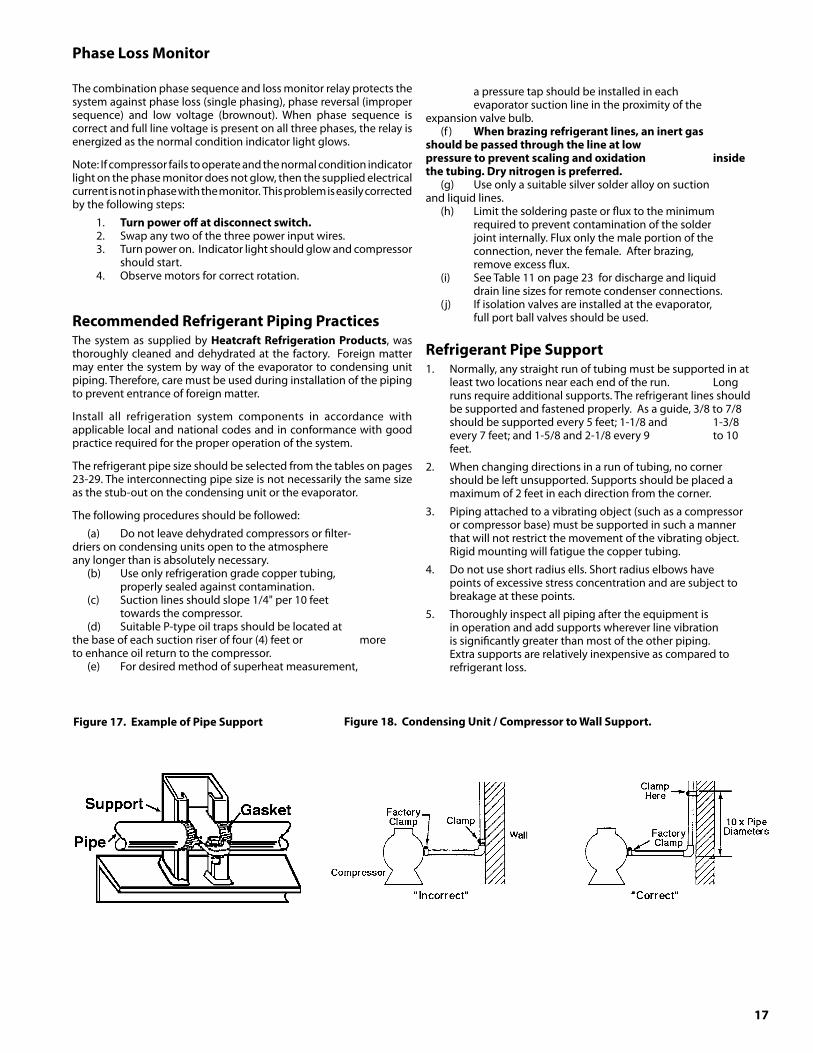
Figure17.ExampleofPipeSupport Figure18.CondensingUnit/CompressortoWallSupport.
a pressure tap should be installed in each evaporator suction line in the proximity of the expansion valve bulb.
(f ) Whenbrazingrefrigerantlines,aninertgas shouldbepassedthroughthelineatlow pressuretopreventscalingandoxidation insidethetubing.Drynitrogenispreferred.
(g) Use only a suitable silver solder alloy on suction and liquid lines.
(h) Limit the soldering paste or flux to the minimum required to prevent contamination of the solder joint internally. Flux only the male portion of the connection, never the female. After brazing, remove excess flux.
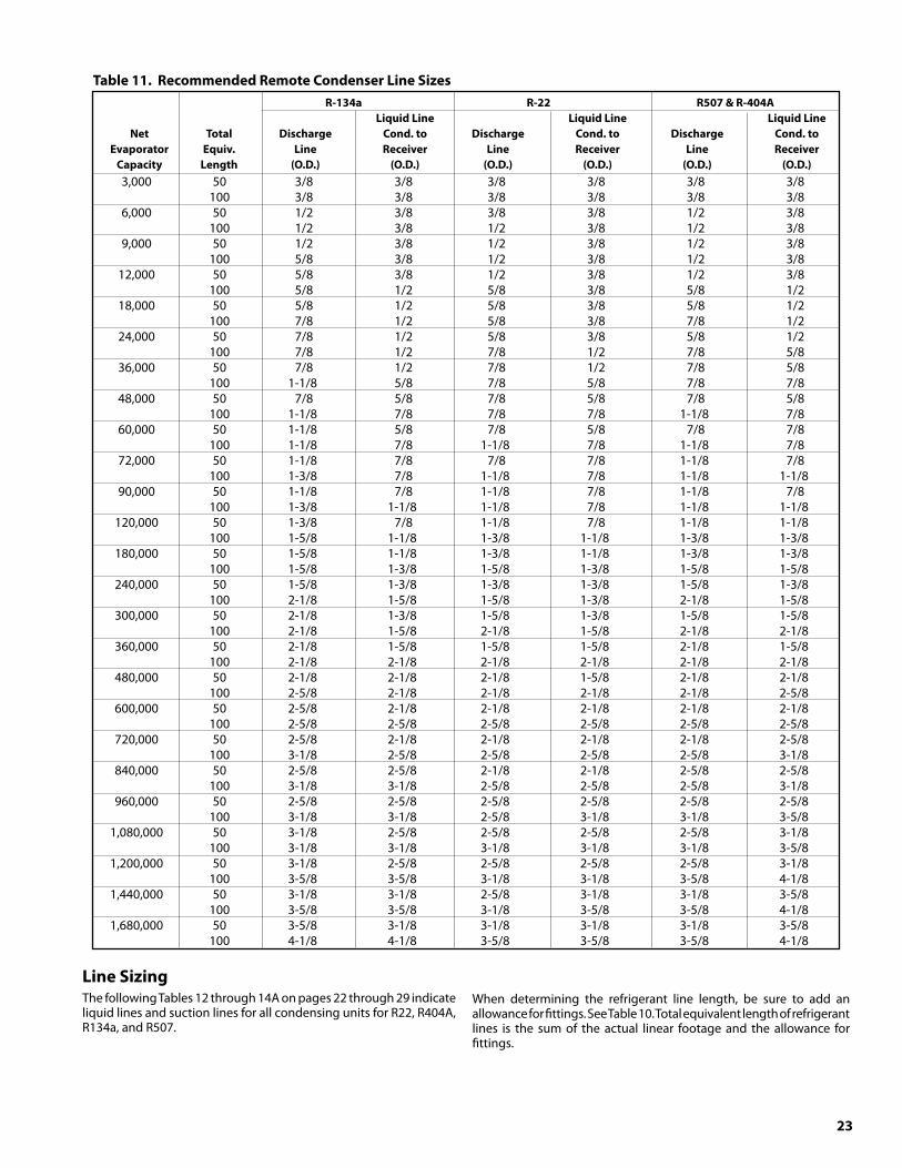
(i) See Table 11 on page 23 for discharge and liquid drain line sizes for remote condenser connections.
(j) If isolation valves are installed at the evaporator, full port ball valves should be used.
RefrigerantPipeSupport1. Normally, any straight run of tubing must be supported in at
least two locations near each end of the run. Long runs require additional supports. The refrigerant lines should be supported and fastened properly. As a guide, 3/8 to 7/8 should be supported every 5 feet; 1-1/8 and 1-3/8 every 7 feet; and 1-5/8 and 2-1/8 every 9 to 10 feet.
2. When changing directions in a run of tubing, no corner should be left unsupported. Supports should be placed a maximum of 2 feet in each direction from the corner.
3. Piping attached to a vibrating object (such as a compressor or compressor base) must be supported in such a manner that will not restrict the movement of the vibrating object. Rigid mounting will fatigue the copper tubing.
4. Do not use short radius ells. Short radius elbows have points of excessive stress concentration and are subject to breakage at these points.
5. Thoroughly inspect all piping after the equipment is in operation and add supports wherever line vibration is significantly greater than most of the other piping. Extra supports are relatively inexpensive as compared to refrigerant loss.
18
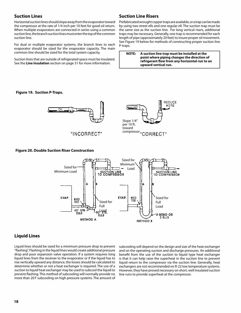
SuctionLinesHorizontal suction lines should slope away from the evaporator toward the compressor at the rate of 1/4 inch per 10 feet for good oil return. When multiple evaporators are connected in series using a common suction line, the branch suction lines must enter the top of the common suction line.
For dual or multiple evaporator systems, the branch lines to each evaporator should be sized for the evaporator capacity. The main common line should be sized for the total system capacity.
Suction lines that are outside of refrigerated space must be insulated. See the LineInsulation section on page 31 for more information.
Figure20.DoubleSuctionRiserConstruction
Figure19.SuctionP-Traps.
Slope 1/4" per 10 ft. toward compressor
LiquidLines
Liquid lines should be sized for a minimum pressure drop to prevent “flashing”. Flashing in the liquid lines would create additional pressure drop and poor expansion valve operation. If a system requires long liquid lines from the receiver to the evaporator or if the liquid has to rise vertically upward any distance, the losses should be calculated to determine whether or not a heat exchanger is required. The use of a suction to liquid heat exchanger may be used to subcool the liquid to prevent flashing. This method of subcooling will normally provide no more than 20˚F subcooling on high pressure systems. The amount of
subcooling will depend on the design and size of the heat exchanger and on the operating suction and discharge pressures. An additional benefit from the use of the suction to liquid type heat exchanger is that it can help raise the superheat in the suction line to prevent liquid return to the compressor via the suction line. Generally, heat exchangers are not recommended on R-22 low temperature systems. However, they have proved necessary on short, well insulated suction line runs to provide superheat at the compressor.
SuctionLineRisersPrefabricated wrought copper traps are available, or a trap can be made by using two street ells and one regular ell. The suction trap must be the same size as the suction line. For long vertical risers, additional traps may be necessary. Generally, one trap is recommended for each length of pipe (approximately 20 feet) to insure proper oil movement. See Figure 19 below for methods of constructing proper suction line P-traps.
Sized forMinimum Load
Sized forFullLoad
Sized forMinimum
Load
Sized forFullLoad
NOTE: Asuctionlinetrapmustbeinstalledatthe pointwherepipingchangesthedirectionof refrigerantflowfromanyhorizontalruntoan
upwardverticalrun.
19
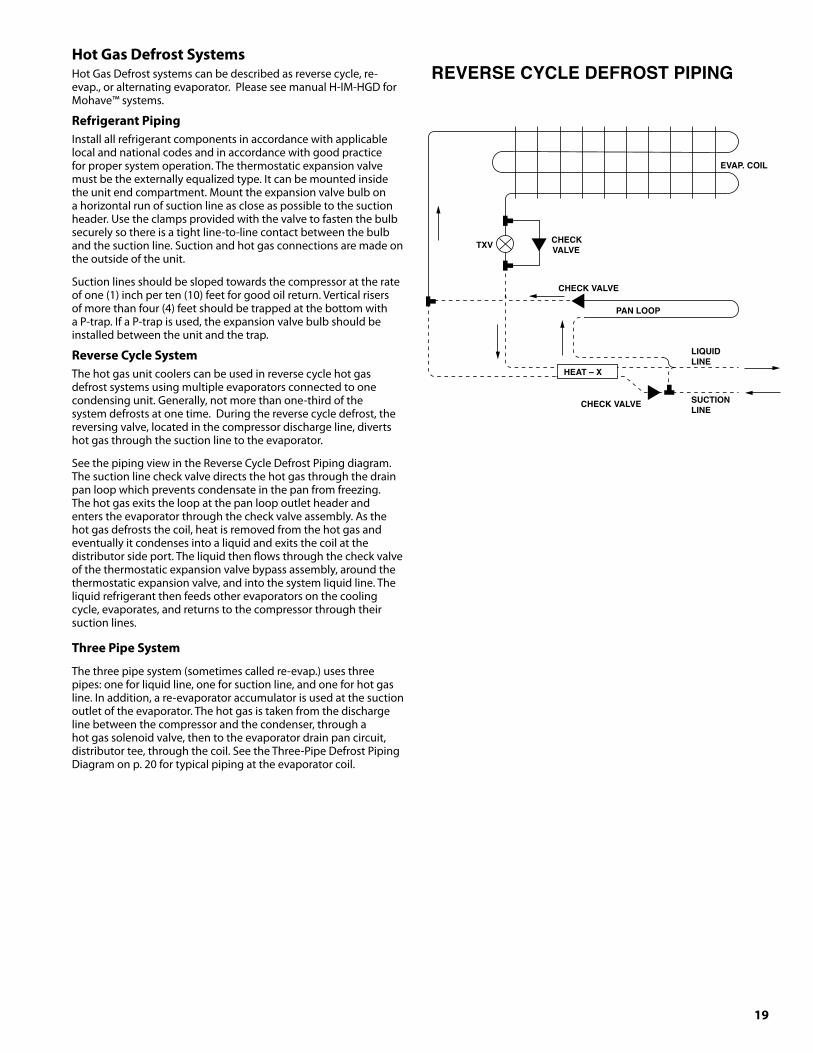
HotGasDefrostSystemsHot Gas Defrost systems can be described as reverse cycle, re-evap., or alternating evaporator. Please see manual H-IM-HGD for Mohave™ systems.
RefrigerantPipingInstall all refrigerant components in accordance with applicable local and national codes and in accordance with good practice for proper system operation. The thermostatic expansion valve must be the externally equalized type. It can be mounted inside the unit end compartment. Mount the expansion valve bulb on a horizontal run of suction line as close as possible to the suction header. Use the clamps provided with the valve to fasten the bulb securely so there is a tight line-to-line contact between the bulb and the suction line. Suction and hot gas connections are made on the outside of the unit.
Suction lines should be sloped towards the compressor at the rate of one (1) inch per ten (10) feet for good oil return. Vertical risers of more than four (4) feet should be trapped at the bottom with a P-trap. If a P-trap is used, the expansion valve bulb should be installed between the unit and the trap.
ReverseCycleSystemThe hot gas unit coolers can be used in reverse cycle hot gas defrost systems using multiple evaporators connected to one condensing unit. Generally, not more than one-third of the system defrosts at one time. During the reverse cycle defrost, the reversing valve, located in the compressor discharge line, diverts hot gas through the suction line to the evaporator.
See the piping view in the Reverse Cycle Defrost Piping diagram. The suction line check valve directs the hot gas through the drain pan loop which prevents condensate in the pan from freezing. The hot gas exits the loop at the pan loop outlet header and enters the evaporator through the check valve assembly. As the hot gas defrosts the coil, heat is removed from the hot gas and eventually it condenses into a liquid and exits the coil at the distributor side port. The liquid then flows through the check valve of the thermostatic expansion valve bypass assembly, around the thermostatic expansion valve, and into the system liquid line. The liquid refrigerant then feeds other evaporators on the cooling cycle, evaporates, and returns to the compressor through their suction lines.
ThreePipeSystem
The three pipe system (sometimes called re-evap.) uses three pipes: one for liquid line, one for suction line, and one for hot gas line. In addition, a re-evaporator accumulator is used at the suction outlet of the evaporator. The hot gas is taken from the discharge line between the compressor and the condenser, through a hot gas solenoid valve, then to the evaporator drain pan circuit, distributor tee, through the coil. See the Three-Pipe Defrost Piping Diagram on p. 20 for typical piping at the evaporator coil.
EVAP. COIL
TXV
PAN LOOP
CHECK VALVE
REVERSE CYCLE DEFROST PIPING
CHECK VALVE
CHECKVALVE
LIQUIDLINE
SUCTIONLINE
HEAT – X

20
AlternatingEvaporatorSystem
In the alternating evaporator hot gas defrost system, a third line is taken off the compressor discharge line as the re-evap system. It is piped with solenoids at each evaporator, so that hot gas defrost is accomplished on one or more evaporators while the remaining
evaporators continue to function in a normal manner. The liquid from defrosting evaporators is reintroduced to the main liquid line and it is necessary that 75% or greater capacity be retained in the normal refrigeration cycle to offset the capacity that is being removed by the units on the hot gas defrost.
HotgaslinesizesforR-22,R404AandR507
SystemCapacityBTU/Hr
EquivalentDischargeLength(Ft.)
25 50 75 100 150
4,000 1/2 1/2 1/2 1/2 1/2
5,000 1/2 1/2 1/2 1/2 1/2
6,000 1/2 1/2 1/2 5/8 5/8
7,000 1/2 1/2 5/8 5/8 5/8
8,000 1/2 5/8 5/8 5/8 5/8
9,000 1/2 5/8 5/8 5/8 5/8
10,000 1/2 5/8 5/8 5/8 5/8
12,000 5/8 5/8 5/8 7/8 7/8
14,000 5/8 5/8 7/8 7/8 7/8
16,000 5/8 5/8 7/8 7/8 7/8
18,000 5/8 7/8 7/8 7/8 7/8
20,000 5/8 7/8 7/8 7/8 7/8
25,000 7/8 7/8 7/8 7/8 1 1/8
30,000 7/8 7/8 7/8 1 1/8 1 1/8
35,000 7/8 7/8 1 1/8 1 1/8 1 1/8
40,000 7/8 1 1/8 1 1/8 1 1/8 1 1/8
45,000 7/8 1 1/8 1 1/8 1 1/8 1 1/8
50,000 7/8 1 1/8 1 1/8 1 1/8 1 1/8
60,000 1 1/8 1 1/8 1 1/8 1 3/8 1 3/8
70,000 1 1/8 1 1/8 1 3/8 1 3/8 1 3/8
80,000 1 1/8 1 1/8 1 3/8 1 3/8 1 5/8
90,000 1 1/8 1 3/8 1 3/8 1 5/8 1 5/8
100,000 1 1/8 1 3/8 1 3/8 1 5/8 1 5/8
Note: Use next larger hot gas line size for -200F. and lower sucton temperatures.
IMPORTANT: It is imperative that with the alternatingevaporatorhotgasdefrostsystem,nomorethat25%oftheoperatingrefrigerationloadbeindefrostatanytime.
EVAP. COIL
TXV
PAN LOOP
THREE-PIPE DEFROST PIPING
CHECKVALVE
HOT GAS LINE
LIQUID LINESUCTION LINE
HEAT – X
21
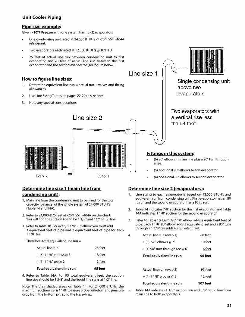
Pipesizeexample:Given: -10°FFreezer with one system having (2) evaporators
• One condensing unit rated at 24,000 BTUH’s @ -20°F SST R404A refrigerant.
• Two evaporators each rated at 12,000 BTUH’s @ 10°F TD.
• 75 feet of actual line run between condensing unit to first evaporator and 20 feet of actual line run between the first evaporator and the second evaporator (see figure below).
Howtofigurelinesizes:1. Determine equivalent line run = actual run + valves and fitting
allowances.
2. Use Line Sizing Tables on pages 22-29 to size lines.
3. Note any special considerations.
Fittingsinthissystem:• (6) 90° elbows in main line plus a 90° turn through
a tee.
• (5) addtional 90° elbows to first evaporator.
• (4) additional 90° elbows to second evaporator.
Determinelinesize1(mainlinefromcondensingunit):1. Main line from the condensing unit to be sized for the total capacity (balance) of the whole system of 24,000 BTUH’s (Table 14 and 14A).
2. Refer to 24,000 @75 feet at -20°F SST R404A on the chart. You will find the suction line to be 1 1/8" and 1/2" liquid line.
3. Refer to Table 10. For every 1 1/8" 90° elbow you must add 3 equivalent feet of pipe and 2 equivalent feet of pipe for each 1 1/8" tee.
Therefore, total equivalent line run =
Actual line run 75 feet
+ (6) 1 1/8" elbows @ 3' 18 feet
+ (1) 1 1/8" tee @ 2' 2 feet
Totalequivalentlinerun 95feet
4. Refer to Table 14A. For 95 total equivalent feet, the suction line size should be 1 3/8" and the liquid line stays at 1/2" line.
Note: The gray shaded areas on Table 14. For 24,000 BTUH’s, the maximum suction riser is 1 1/8" to insure proper oil return and pressure drop from the bottom p-trap to the top p-trap.
Determinelinesize2(evaporators):1. Line sizing to each evaporator is based on 12,000 BTUH’s and
equivalent run from condensing unit. First evaporator has an 80 ft. run and the second evaporator has a 95 ft. run.
2. Table 14 indicates 7/8" suction for the first evaporator and Table 14A indicates 1 1/8" suction for the second evaporator.
3. Refer to Table 10. Each 7/8" 90° elbow adds 2 equivalent feet of pipe. Each 1 1/8" 90° elbow adds 3 equivalent feet and a 90° turn through a 1 1/8" tee adds 6 equivalent feet.
4. Actual line run (evap 1) 80 feet
+ (5) 7/8" elbows @ 2' 10 feet
+ (1) 90° turn through tee @ 6' 6 feet
Totalequivalentlinerun 96feet
Actual line run (evap 2) 95 feet
+ (4) 1 1/8" elbows @ 3' 12 feet
Totalequivalentlinerun 107feet
5. Table 14A indicates 1 1/8" suction line and 3/8" liquid line from main line to both evaporators.
UnitCoolerPiping
Evap. 1Evap. 2
22
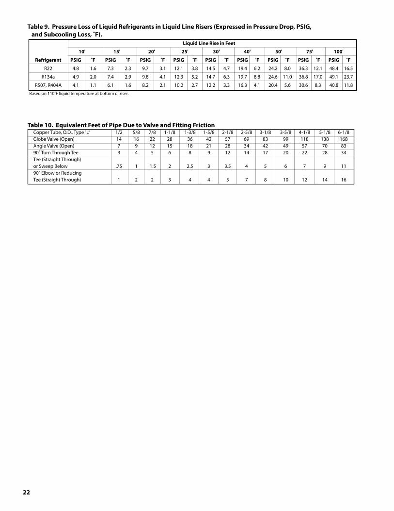
Table10.EquivalentFeetofPipeDuetoValveandFittingFriction Copper Tube, O.D., Type “L” 1/2 5/8 7/8 1-1/8 1-3/8 1-5/8 2-1/8 2-5/8 3-1/8 3-5/8 4-1/8 5-1/8 6-1/8 Globe Valve (Open) 14 16 22 28 36 42 57 69 83 99 118 138 168 Angle Valve (Open) 7 9 12 15 18 21 28 34 42 49 57 70 83 90˚ Turn Through Tee 3 4 5 6 8 9 12 14 17 20 22 28 34 Tee (Straight Through) or Sweep Below .75 1 1.5 2 2.5 3 3.5 4 5 6 7 9 11 90˚ Elbow or Reducing Tee (Straight Through) 1 2 2 3 4 4 5 7 8 10 12 14 16
Table9.PressureLossofLiquidRefrigerantsinLiquidLineRisers(ExpressedinPressureDrop,PSIG, andSubcoolingLoss,˚F). LiquidLineRiseinFeet
10' 15' 20' 25' �0' 40' 50' 75' 100'
Refrigerant PSIG ˚F PSIG ˚F PSIG ˚F PSIG ˚F PSIG ˚F PSIG ˚F PSIG ˚F PSIG ˚F PSIG ˚F
R22 4.8 1.6 7.3 2.3 9.7 3.1 12.1 3.8 14.5 4.7 19.4 6.2 24.2 8.0 36.3 12.1 48.4 16.5
R134a 4.9 2.0 7.4 2.9 9.8 4.1 12.3 5.2 14.7 6.3 19.7 8.8 24.6 11.0 36.8 17.0 49.1 23.7
R507, R404A 4.1 1.1 6.1 1.6 8.2 2.1 10.2 2.7 12.2 3.3 16.3 4.1 20.4 5.6 30.6 8.3 40.8 11.8
Based on 110˚F liquid temperature at bottom of riser.
2�
Table11.RecommendedRemoteCondenserLineSizes R-1�4a R-22 R507&R-404A LiquidLine LiquidLine LiquidLine Net Total Discharge Cond.to Discharge Cond.to Discharge Cond.to Evaporator Equiv. Line Receiver Line Receiver Line Receiver Capacity Length (O.D.) (O.D.) (O.D.) (O.D.) (O.D.) (O.D.) 3,000 50 3/8 3/8 3/8 3/8 3/8 3/8 100 3/8 3/8 3/8 3/8 3/8 3/8 6,000 50 1/2 3/8 3/8 3/8 1/2 3/8 100 1/2 3/8 1/2 3/8 1/2 3/8 9,000 50 1/2 3/8 1/2 3/8 1/2 3/8 100 5/8 3/8 1/2 3/8 1/2 3/8 12,000 50 5/8 3/8 1/2 3/8 1/2 3/8 100 5/8 1/2 5/8 3/8 5/8 1/2 18,000 50 5/8 1/2 5/8 3/8 5/8 1/2 100 7/8 1/2 5/8 3/8 7/8 1/2 24,000 50 7/8 1/2 5/8 3/8 5/8 1/2 100 7/8 1/2 7/8 1/2 7/8 5/8 36,000 50 7/8 1/2 7/8 1/2 7/8 5/8 100 1-1/8 5/8 7/8 5/8 7/8 7/8 48,000 50 7/8 5/8 7/8 5/8 7/8 5/8 100 1-1/8 7/8 7/8 7/8 1-1/8 7/8 60,000 50 1-1/8 5/8 7/8 5/8 7/8 7/8 100 1-1/8 7/8 1-1/8 7/8 1-1/8 7/8 72,000 50 1-1/8 7/8 7/8 7/8 1-1/8 7/8 100 1-3/8 7/8 1-1/8 7/8 1-1/8 1-1/8 90,000 50 1-1/8 7/8 1-1/8 7/8 1-1/8 7/8 100 1-3/8 1-1/8 1-1/8 7/8 1-1/8 1-1/8 120,000 50 1-3/8 7/8 1-1/8 7/8 1-1/8 1-1/8 100 1-5/8 1-1/8 1-3/8 1-1/8 1-3/8 1-3/8 180,000 50 1-5/8 1-1/8 1-3/8 1-1/8 1-3/8 1-3/8 100 1-5/8 1-3/8 1-5/8 1-3/8 1-5/8 1-5/8 240,000 50 1-5/8 1-3/8 1-3/8 1-3/8 1-5/8 1-3/8 100 2-1/8 1-5/8 1-5/8 1-3/8 2-1/8 1-5/8 300,000 50 2-1/8 1-3/8 1-5/8 1-3/8 1-5/8 1-5/8 100 2-1/8 1-5/8 2-1/8 1-5/8 2-1/8 2-1/8 360,000 50 2-1/8 1-5/8 1-5/8 1-5/8 2-1/8 1-5/8 100 2-1/8 2-1/8 2-1/8 2-1/8 2-1/8 2-1/8 480,000 50 2-1/8 2-1/8 2-1/8 1-5/8 2-1/8 2-1/8 100 2-5/8 2-1/8 2-1/8 2-1/8 2-1/8 2-5/8 600,000 50 2-5/8 2-1/8 2-1/8 2-1/8 2-1/8 2-1/8 100 2-5/8 2-5/8 2-5/8 2-5/8 2-5/8 2-5/8 720,000 50 2-5/8 2-1/8 2-1/8 2-1/8 2-1/8 2-5/8 100 3-1/8 2-5/8 2-5/8 2-5/8 2-5/8 3-1/8 840,000 50 2-5/8 2-5/8 2-1/8 2-1/8 2-5/8 2-5/8 100 3-1/8 3-1/8 2-5/8 2-5/8 2-5/8 3-1/8 960,000 50 2-5/8 2-5/8 2-5/8 2-5/8 2-5/8 2-5/8 100 3-1/8 3-1/8 2-5/8 3-1/8 3-1/8 3-5/8 1,080,000 50 3-1/8 2-5/8 2-5/8 2-5/8 2-5/8 3-1/8 100 3-1/8 3-1/8 3-1/8 3-1/8 3-1/8 3-5/8 1,200,000 50 3-1/8 2-5/8 2-5/8 2-5/8 2-5/8 3-1/8 100 3-5/8 3-5/8 3-1/8 3-1/8 3-5/8 4-1/8 1,440,000 50 3-1/8 3-1/8 2-5/8 3-1/8 3-1/8 3-5/8 100 3-5/8 3-5/8 3-1/8 3-5/8 3-5/8 4-1/8 1,680,000 50 3-5/8 3-1/8 3-1/8 3-1/8 3-1/8 3-5/8 100 4-1/8 4-1/8 3-5/8 3-5/8 3-5/8 4-1/8
LineSizingThe following Tables 12 through 14A on pages 22 through 29 indicate liquid lines and suction lines for all condensing units for R22, R404A, R134a, and R507.
When determining the refrigerant line length, be sure to add an allowance for fittings. See Table 10. Total equivalent length of refrigerant lines is the sum of the actual linear footage and the allowance for fittings.
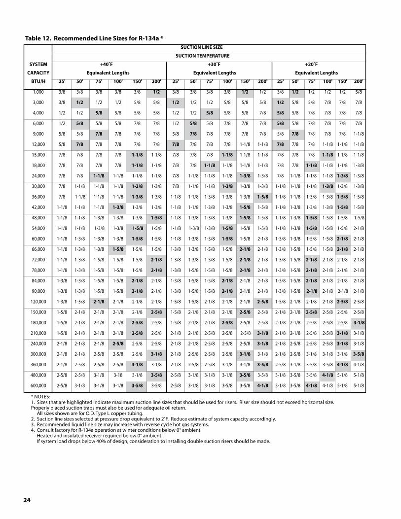
24
Table12.RecommendedLineSizesforR-1�4a* SUCTIONLINESIZE
SUCTIONTEMPERATURE
SYSTEM +40˚F +�0˚F +20˚F
CAPACITY EquivalentLengths EquivalentLengths EquivalentLengths
BTU/H 25' 50' 75' 100' 150' 200' 25' 50' 75' 100' 150' 200' 25' 50' 75' 100' 150' 200'
1,000 3/8 3/8 3/8 3/8 3/8 1/2 3/8 3/8 3/8 3/8 1/2 1/2 3/8 1/2 1/2 1/2 1/2 5/8
3,000 3/8 1/2 1/2 1/2 5/8 5/8 1/2 1/2 1/2 5/8 5/8 5/8 1/2 5/8 5/8 7/8 7/8 7/8
4,000 1/2 1/2 5/8 5/8 5/8 5/8 1/2 1/2 5/8 5/8 5/8 7/8 5/8 5/8 7/8 7/8 7/8 7/8
6,000 1/2 5/8 5/8 5/8 7/8 7/8 1/2 5/8 5/8 7/8 7/8 7/8 5/8 5/8 7/8 7/8 7/8 7/8
9,000 5/8 5/8 7/8 7/8 7/8 7/8 5/8 7/8 7/8 7/8 7/8 7/8 5/8 7/8 7/8 7/8 7/8 1-1/8
12,000 5/8 7/8 7/8 7/8 7/8 7/8 7/8 7/8 7/8 7/8 1-1/8 1-1/8 7/8 7/8 7/8 1-1/8 1-1/8 1-1/8
15,000 7/8 7/8 7/8 7/8 1-1/8 1-1/8 7/8 7/8 7/8 1-1/8 1-1/8 1-1/8 7/8 7/8 7/8 1-1/8 1-1/8 1-1/8
18,000 7/8 7/8 7/8 7/8 1-1/8 1-1/8 7/8 7/8 1-1/8 1-1/8 1-1/8 1-1/8 7/8 7/8 1-1/8 1-1/8 1-1/8 1-3/8
24,000 7/8 7/8 1-1/8 1-1/8 1-1/8 1-1/8 7/8 1-1/8 1-1/8 1-1/8 1-�/8 1-3/8 7/8 1-1/8 1-1/8 1-1/8 1-�/8 1-3/8
30,000 7/8 1-1/8 1-1/8 1-1/8 1-�/8 1-3/8 7/8 1-1/8 1-1/8 1-�/8 1-3/8 1-3/8 1-1/8 1-1/8 1-1/8 1-�/8 1-3/8 1-3/8
36,000 7/8 1-1/8 1-1/8 1-1/8 1-�/8 1-3/8 1-1/8 1-1/8 1-3/8 1-3/8 1-3/8 1-5/8 1-1/8 1-1/8 1-3/8 1-3/8 1-5/8 1-5/8
42,000 1-1/8 1-1/8 1-1/8 1-�/8 1-3/8 1-3/8 1-1/8 1-1/8 1-3/8 1-3/8 1-5/8 1-5/8 1-1/8 1-3/8 1-3/8 1-3/8 1-5/8 1-5/8
48,000 1-1/8 1-1/8 1-3/8 1-3/8 1-3/8 1-5/8 1-1/8 1-3/8 1-3/8 1-3/8 1-5/8 1-5/8 1-1/8 1-3/8 1-5/8 1-5/8 1-5/8 1-5/8
54,000 1-1/8 1-1/8 1-3/8 1-3/8 1-5/8 1-5/8 1-1/8 1-3/8 1-3/8 1-5/8 1-5/8 1-5/8 1-1/8 1-3/8 1-5/8 1-5/8 1-5/8 2-1/8
60,000 1-1/8 1-3/8 1-3/8 1-3/8 1-5/8 1-5/8 1-1/8 1-3/8 1-3/8 1-5/8 1-5/8 2-1/8 1-3/8 1-3/8 1-5/8 1-5/8 2-1/8 2-1/8
66,000 1-1/8 1-3/8 1-3/8 1-5/8 1-5/8 1-5/8 1-3/8 1-3/8 1-5/8 1-5/8 2-1/8 2-1/8 1-3/8 1-5/8 1-5/8 1-5/8 2-1/8 2-1/8
72,000 1-1/8 1-3/8 1-5/8 1-5/8 1-5/8 2-1/8 1-3/8 1-3/8 1-5/8 1-5/8 2-1/8 2-1/8 1-3/8 1-5/8 2-1/8 2-1/8 2-1/8 2-1/8
78,000 1-1/8 1-3/8 1-5/8 1-5/8 1-5/8 2-1/8 1-3/8 1-5/8 1-5/8 1-5/8 2-1/8 2-1/8 1-3/8 1-5/8 2-1/8 2-1/8 2-1/8 2-1/8
84,000 1-3/8 1-3/8 1-5/8 1-5/8 2-1/8 2-1/8 1-3/8 1-5/8 1-5/8 2-1/8 2-1/8 2-1/8 1-3/8 1-5/8 2-1/8 2-1/8 2-1/8 2-1/8
90,000 1-3/8 1-3/8 1-5/8 1-5/8 2-1/8 2-1/8 1-3/8 1-5/8 1-5/8 2-1/8 2-1/8 2-1/8 1-3/8 1-5/8 2-1/8 2-1/8 2-1/8 2-1/8
120,000 1-3/8 1-5/8 2-1/8 2-1/8 2-1/8 2-1/8 1-5/8 1-5/8 2-1/8 2-1/8 2-1/8 2-5/8 1-5/8 2-1/8 2-1/8 2-1/8 2-5/8 2-5/8
150,000 1-5/8 2-1/8 2-1/8 2-1/8 2-1/8 2-5/8 1-5/8 2-1/8 2-1/8 2-1/8 2-5/8 2-5/8 2-1/8 2-1/8 2-5/8 2-5/8 2-5/8 2-5/8
180,000 1-5/8 2-1/8 2-1/8 2-1/8 2-5/8 2-5/8 1-5/8 2-1/8 2-1/8 2-5/8 2-5/8 2-5/8 2-1/8 2-1/8 2-5/8 2-5/8 2-5/8 �-1/8
210,000 1-5/8 2-1/8 2-1/8 2-1/8 2-5/8 2-5/8 2-1/8 2-1/8 2-5/8 2-5/8 2-5/8 �-1/8 2-1/8 2-1/8 2-5/8 2-5/8 �-1/8 3-1/8
240,000 2-1/8 2-1/8 2-1/8 2-5/8 2-5/8 2-5/8 2-1/8 2-1/8 2-5/8 2-5/8 2-5/8 �-1/8 2-1/8 2-5/8 2-5/8 2-5/8 �-1/8 3-1/8
300,000 2-1/8 2-1/8 2-5/8 2-5/8 2-5/8 �-1/8 2-1/8 2-5/8 2-5/8 2-5/8 �-1/8 3-1/8 2-1/8 2-5/8 3-1/8 3-1/8 3-1/8 �-5/8
360,000 2-1/8 2-5/8 2-5/8 2-5/8 �-1/8 3-1/8 2-1/8 2-5/8 2-5/8 3-1/8 3-1/8 �-5/8 2-5/8 3-1/8 3-5/8 3-5/8 4-1/8 4-1/8
480,000 2-5/8 2-5/8 3-1/8 3-18 3-1/8 �-5/8 2-5/8 3-1/8 3-1/8 3-1/8 �-5/8 3-5/8 3-1/8 3-5/8 3-5/8 4-1/8 5-1/8 5-1/8
600,000 2-5/8 3-1/8 3-1/8 3-1/8 �-5/8 3-5/8 2-5/8 3-1/8 3-1/8 3-5/8 3-5/8 4-1/8 3-1/8 3-5/8 4-1/8 4-1/8 5-1/8 5-1/8
* NOTES: 1. Sizes that are highlighted indicate maximum suction line sizes that should be used for risers. Riser size should not exceed horizontal size. Properly placed suction traps must also be used for adequate oil return. All sizes shown are for O.D. Type L copper tubing. 2. Suction line sizes selected at pressure drop equivalent to 2˚F. Reduce estimate of system capacity accordingly. 3. Recommended liquid line size may increase with reverse cycle hot gas systems. 4. Consult factory for R-134a operation at winter conditions below 0° ambient. Heated and insulated receiver required below 0° ambient. If system load drops below 40% of design, consideration to installing double suction risers should be made.
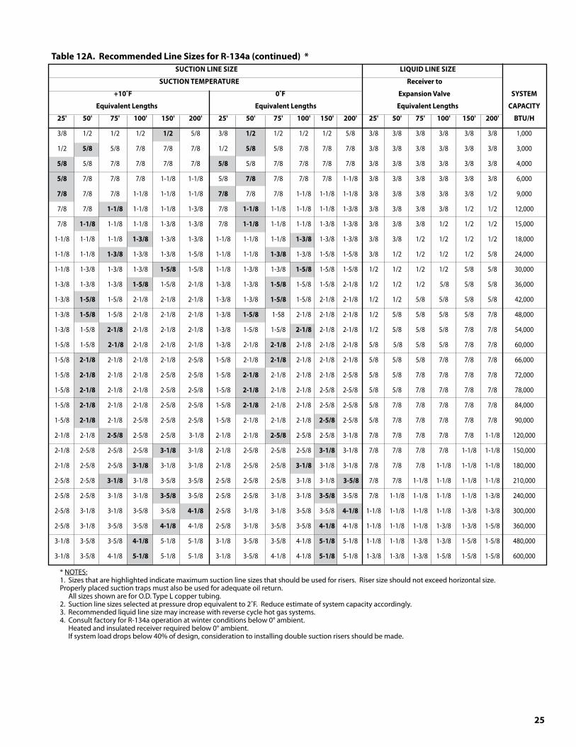
25
Table12A.RecommendedLineSizesforR-1�4a(continued)* SUCTIONLINESIZE LIQUIDLINESIZE
SUCTIONTEMPERATURE Receiverto
+10˚F 0˚F ExpansionValve SYSTEM
EquivalentLengths EquivalentLengths EquivalentLengths CAPACITY
25' 50' 75' 100' 150' 200' 25' 50' 75' 100' 150' 200' 25' 50' 75' 100' 150' 200' BTU/H
3/8 1/2 1/2 1/2 1/2 5/8 3/8 1/2 1/2 1/2 1/2 5/8 3/8 3/8 3/8 3/8 3/8 3/8 1,000
1/2 5/8 5/8 7/8 7/8 7/8 1/2 5/8 5/8 7/8 7/8 7/8 3/8 3/8 3/8 3/8 3/8 3/8 3,000
5/8 5/8 7/8 7/8 7/8 7/8 5/8 5/8 7/8 7/8 7/8 7/8 3/8 3/8 3/8 3/8 3/8 3/8 4,000
5/8 7/8 7/8 7/8 1-1/8 1-1/8 5/8 7/8 7/8 7/8 7/8 1-1/8 3/8 3/8 3/8 3/8 3/8 3/8 6,000
7/8 7/8 7/8 1-1/8 1-1/8 1-1/8 7/8 7/8 7/8 1-1/8 1-1/8 1-1/8 3/8 3/8 3/8 3/8 3/8 1/2 9,000
7/8 7/8 1-1/8 1-1/8 1-1/8 1-3/8 7/8 1-1/8 1-1/8 1-1/8 1-1/8 1-3/8 3/8 3/8 3/8 3/8 1/2 1/2 12,000
7/8 1-1/8 1-1/8 1-1/8 1-3/8 1-3/8 7/8 1-1/8 1-1/8 1-1/8 1-3/8 1-3/8 3/8 3/8 3/8 1/2 1/2 1/2 15,000
1-1/8 1-1/8 1-1/8 1-�/8 1-3/8 1-3/8 1-1/8 1-1/8 1-1/8 1-�/8 1-3/8 1-3/8 3/8 3/8 1/2 1/2 1/2 1/2 18,000
1-1/8 1-1/8 1-�/8 1-3/8 1-3/8 1-5/8 1-1/8 1-1/8 1-�/8 1-3/8 1-5/8 1-5/8 3/8 1/2 1/2 1/2 1/2 5/8 24,000
1-1/8 1-3/8 1-3/8 1-3/8 1-5/8 1-5/8 1-1/8 1-3/8 1-3/8 1-5/8 1-5/8 1-5/8 1/2 1/2 1/2 1/2 5/8 5/8 30,000
1-3/8 1-3/8 1-3/8 1-5/8 1-5/8 2-1/8 1-3/8 1-3/8 1-5/8 1-5/8 1-5/8 2-1/8 1/2 1/2 1/2 5/8 5/8 5/8 36,000
1-3/8 1-5/8 1-5/8 2-1/8 2-1/8 2-1/8 1-3/8 1-3/8 1-5/8 1-5/8 2-1/8 2-1/8 1/2 1/2 5/8 5/8 5/8 5/8 42,000
1-3/8 1-5/8 1-5/8 2-1/8 2-1/8 2-1/8 1-3/8 1-5/8 1-58 2-1/8 2-1/8 2-1/8 1/2 5/8 5/8 5/8 5/8 7/8 48,000
1-3/8 1-5/8 2-1/8 2-1/8 2-1/8 2-1/8 1-3/8 1-5/8 1-5/8 2-1/8 2-1/8 2-1/8 1/2 5/8 5/8 5/8 7/8 7/8 54,000
1-5/8 1-5/8 2-1/8 2-1/8 2-1/8 2-1/8 1-3/8 2-1/8 2-1/8 2-1/8 2-1/8 2-1/8 5/8 5/8 5/8 5/8 7/8 7/8 60,000
1-5/8 2-1/8 2-1/8 2-1/8 2-1/8 2-5/8 1-5/8 2-1/8 2-1/8 2-1/8 2-1/8 2-1/8 5/8 5/8 5/8 7/8 7/8 7/8 66,000
1-5/8 2-1/8 2-1/8 2-1/8 2-5/8 2-5/8 1-5/8 2-1/8 2-1/8 2-1/8 2-1/8 2-5/8 5/8 5/8 7/8 7/8 7/8 7/8 72,000
1-5/8 2-1/8 2-1/8 2-1/8 2-5/8 2-5/8 1-5/8 2-1/8 2-1/8 2-1/8 2-5/8 2-5/8 5/8 5/8 7/8 7/8 7/8 7/8 78,000
1-5/8 2-1/8 2-1/8 2-1/8 2-5/8 2-5/8 1-5/8 2-1/8 2-1/8 2-1/8 2-5/8 2-5/8 5/8 7/8 7/8 7/8 7/8 7/8 84,000
1-5/8 2-1/8 2-1/8 2-5/8 2-5/8 2-5/8 1-5/8 2-1/8 2-1/8 2-1/8 2-5/8 2-5/8 5/8 7/8 7/8 7/8 7/8 7/8 90,000
2-1/8 2-1/8 2-5/8 2-5/8 2-5/8 3-1/8 2-1/8 2-1/8 2-5/8 2-5/8 2-5/8 3-1/8 7/8 7/8 7/8 7/8 7/8 1-1/8 120,000
2-1/8 2-5/8 2-5/8 2-5/8 �-1/8 3-1/8 2-1/8 2-5/8 2-5/8 2-5/8 �-1/8 3-1/8 7/8 7/8 7/8 7/8 1-1/8 1-1/8 150,000
2-1/8 2-5/8 2-5/8 �-1/8 3-1/8 3-1/8 2-1/8 2-5/8 2-5/8 �-1/8 3-1/8 3-1/8 7/8 7/8 7/8 1-1/8 1-1/8 1-1/8 180,000
2-5/8 2-5/8 �-1/8 3-1/8 3-5/8 3-5/8 2-5/8 2-5/8 2-5/8 3-1/8 3-1/8 �-5/8 7/8 7/8 1-1/8 1-1/8 1-1/8 1-1/8 210,000
2-5/8 2-5/8 3-1/8 3-1/8 �-5/8 3-5/8 2-5/8 2-5/8 3-1/8 3-1/8 �-5/8 3-5/8 7/8 1-1/8 1-1/8 1-1/8 1-1/8 1-3/8 240,000
2-5/8 3-1/8 3-1/8 3-5/8 3-5/8 4-1/8 2-5/8 3-1/8 3-1/8 3-5/8 3-5/8 4-1/8 1-1/8 1-1/8 1-1/8 1-1/8 1-3/8 1-3/8 300,000
2-5/8 3-1/8 3-5/8 3-5/8 4-1/8 4-1/8 2-5/8 3-1/8 3-5/8 3-5/8 4-1/8 4-1/8 1-1/8 1-1/8 1-1/8 1-3/8 1-3/8 1-5/8 360,000
3-1/8 3-5/8 3-5/8 4-1/8 5-1/8 5-1/8 3-1/8 3-5/8 3-5/8 4-1/8 5-1/8 5-1/8 1-1/8 1-1/8 1-3/8 1-3/8 1-5/8 1-5/8 480,000
3-1/8 3-5/8 4-1/8 5-1/8 5-1/8 5-1/8 3-1/8 3-5/8 4-1/8 4-1/8 5-1/8 5-1/8 1-3/8 1-3/8 1-3/8 1-5/8 1-5/8 1-5/8 600,000
* NOTES: 1. Sizes that are highlighted indicate maximum suction line sizes that should be used for risers. Riser size should not exceed horizontal size. Properly placed suction traps must also be used for adequate oil return. All sizes shown are for O.D. Type L copper tubing. 2. Suction line sizes selected at pressure drop equivalent to 2˚F. Reduce estimate of system capacity accordingly. 3. Recommended liquid line size may increase with reverse cycle hot gas systems. 4. Consult factory for R-134a operation at winter conditions below 0° ambient. Heated and insulated receiver required below 0° ambient. If system load drops below 40% of design, consideration to installing double suction risers should be made.
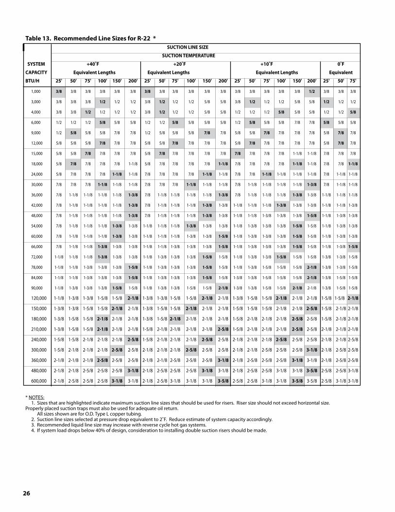
26
Table1�.RecommendedLineSizesforR-22* SUCTIONLINESIZE
SUCTIONTEMPERATURE
SYSTEM +40˚F +20˚F +10˚F 0˚F
CAPACITY EquivalentLengths EquivalentLengths EquivalentLengths Equivalent
BTU/H 25' 50' 75' 100' 150' 200' 25' 50' 75' 100' 150' 200' 25' 50' 75' 100' 150' 200' 25' 50' 75'
1,000 �/8 3/8 3/8 3/8 3/8 3/8 �/8 3/8 3/8 3/8 3/8 3/8 3/8 3/8 3/8 3/8 3/8 1/2 3/8 3/8 3/8
3,000 3/8 3/8 3/8 1/2 1/2 1/2 3/8 1/2 1/2 1/2 5/8 5/8 3/8 1/2 1/2 1/2 5/8 5/8 1/2 1/2 1/2
4,000 3/8 3/8 1/2 1/2 1/2 1/2 3/8 1/2 1/2 1/2 5/8 5/8 1/2 1/2 1/2 5/8 5/8 5/8 1/2 1/2 5/8
6,000 1/2 1/2 1/2 5/8 5/8 5/8 1/2 1/2 5/8 5/8 5/8 5/8 1/2 5/8 5/8 5/8 7/8 7/8 5/8 5/8 5/8
9,000 1/2 5/8 5/8 5/8 7/8 7/8 1/2 5/8 5/8 5/8 7/8 7/8 5/8 5/8 7/8 7/8 7/8 7/8 5/8 7/8 7/8
12,000 5/8 5/8 5/8 7/8 7/8 7/8 5/8 5/8 7/8 7/8 7/8 7/8 5/8 7/8 7/8 7/8 7/8 7/8 5/8 7/8 7/8
15,000 5/8 5/8 7/8 7/8 7/8 7/8 5/8 7/8 7/8 7/8 7/8 7/8 7/8 7/8 7/8 7/8 1-1/8 1-1/8 7/8 7/8 7/8
18,000 5/8 7/8 7/8 7/8 7/8 1-1/8 5/8 7/8 7/8 7/8 7/8 1-1/8 7/8 7/8 7/8 7/8 1-1/8 1-1/8 7/8 7/8 1-1/8
24,000 5/8 7/8 7/8 7/8 1-1/8 1-1/8 7/8 7/8 7/8 7/8 1-1/8 1-1/8 7/8 7/8 1-1/8 1-1/8 1-1/8 1-1/8 7/8 1-1/8 1-1/8
30,000 7/8 7/8 7/8 1-1/8 1-1/8 1-1/8 7/8 7/8 7/8 1-1/8 1-1/8 1-1/8 7/8 1-1/8 1-1/8 1-1/8 1-1/8 1-�/8 7/8 1-1/8 1-1/8
36,000 7/8 1-1/8 1-1/8 1-1/8 1-1/8 1-�/8 7/8 1-1/8 1-1/8 1-1/8 1-1/8 1-�/8 7/8 1-1/8 1-1/8 1-1/8 1-�/8 1-3/8 1-1/8 1-1/8 1-1/8
42,000 7/8 1-1/8 1-1/8 1-1/8 1-1/8 1-�/8 7/8 1-1/8 1-1/8 1-1/8 1-�/8 1-3/8 1-1/8 1-1/8 1-1/8 1-�/8 1-3/8 1-3/8 1-1/8 1-1/8 1-3/8
48,000 7/8 1-1/8 1-1/8 1-1/8 1-1/8 1-�/8 7/8 1-1/8 1-1/8 1-1/8 1-�/8 1-3/8 1-1/8 1-1/8 1-3/8 1-3/8 1-3/8 1-5/8 1-1/8 1-3/8 1-3/8
54,000 7/8 1-1/8 1-1/8 1-1/8 1-�/8 1-3/8 1-1/8 1-1/8 1-1/8 1-�/8 1-3/8 1-3/8 1-1/8 1-3/8 1-3/8 1-3/8 1-5/8 1-5/8 1-1/8 1-3/8 1-3/8
60,000 7/8 1-1/8 1-1/8 1-1/8 1-�/8 1-3/8 1-1/8 1-1/8 1-1/8 1-3/8 1-3/8 1-5/8 1-1/8 1-3/8 1-3/8 1-3/8 1-5/8 1-5/8 1-1/8 1-3/8 1-3/8
66,000 7/8 1-1/8 1-1/8 1-�/8 1-3/8 1-3/8 1-1/8 1-1/8 1-3/8 1-3/8 1-3/8 1-5/8 1-1/8 1-3/8 1-3/8 1-3/8 1-5/8 1-5/8 1-1/8 1-3/8 1-5/8
72,000 1-1/8 1-1/8 1-1/8 1-�/8 1-3/8 1-3/8 1-1/8 1-3/8 1-3/8 1-3/8 1-5/8 1-5/8 1-1/8 1-3/8 1-3/8 1-5/8 1-5/8 1-5/8 1-3/8 1-3/8 1-5/8
78,000 1-1/8 1-1/8 1-3/8 1-3/8 1-3/8 1-5/8 1-1/8 1-3/8 1-3/8 1-3/8 1-5/8 1-5/8 1-1/8 1-3/8 1-5/8 1-5/8 1-5/8 2-1/8 1-3/8 1-3/8 1-5/8
84,000 1-1/8 1-1/8 1-3/8 1-3/8 1-3/8 1-5/8 1-1/8 1-3/8 1-3/8 1-3/8 1-5/8 1-5/8 1-3/8 1-3/8 1-5/8 1-5/8 1-5/8 2-1/8 1-3/8 1-5/8 1-5/8
90,000 1-1/8 1-3/8 1-3/8 1-3/8 1-5/8 1-5/8 1-1/8 1-3/8 1-3/8 1-5/8 1-5/8 2-1/8 1-3/8 1-3/8 1-5/8 1-5/8 2-1/8 2-1/8 1-3/8 1-5/8 1-5/8
120,000 1-1/8 1-3/8 1-3/8 1-5/8 1-5/8 2-1/8 1-3/8 1-3/8 1-5/8 1-5/8 2-1/8 2-1/8 1-3/8 1-5/8 1-5/8 2-1/8 2-1/8 2-1/8 1-5/8 1-5/8 2-1/8
150,000 1-3/8 1-3/8 1-5/8 1-5/8 2-1/8 2-1/8 1-3/8 1-5/8 1-5/8 2-1/8 2-1/8 2-1/8 1-5/8 1-5/8 1-5/8 2-1/8 2-1/8 2-5/8 1-5/8 2-1/8 2-1/8
180,000 1-3/8 1-5/8 1-5/8 2-1/8 2-1/8 2-1/8 1-3/8 1-5/8 2-1/8 2-1/8 2-1/8 2-1/8 1-5/8 2-1/8 2-1/8 2-1/8 2-5/8 2-5/8 1-5/8 2-1/8 2-1/8
210,000 1-3/8 1-5/8 1-5/8 2-1/8 2-1/8 2-1/8 1-5/8 2-1/8 2-1/8 2-1/8 2-1/8 2-5/8 1-5/8 2-1/8 2-1/8 2-1/8 2-5/8 2-5/8 2-1/8 2-1/8 2-1/8
240,000 1-5/8 1-5/8 2-1/8 2-1/8 2-1/8 2-5/8 1-5/8 2-1/8 2-1/8 2-1/8 2-5/8 2-5/8 2-1/8 2-1/8 2-1/8 2-5/8 2-5/8 2-5/8 2-1/8 2-1/8 2-5/8
300,000 1-5/8 2-1/8 2-1/8 2-1/8 2-5/8 2-5/8 2-1/8 2-1/8 2-1/8 2-5/8 2-5/8 2-5/8 2-1/8 2-1/8 2-5/8 2-5/8 2-5/8 �-1/8 2-1/8 2-5/8 2-5/8
360,000 2-1/8 2-1/8 2-1/8 2-5/8 2-5/8 2-5/8 2-1/8 2-1/8 2-5/8 2-5/8 2-5/8 �-1/8 2-1/8 2-5/8 2-5/8 2-5/8 �-1/8 3-1/8 2-1/8 2-5/8 2-5/8
480,000 2-1/8 2-1/8 2-5/8 2-5/8 2-5/8 �-1/8 2-1/8 2-5/8 2-5/8 2-5/8 �-1/8 3-1/8 2-1/8 2-5/8 2-5/8 3-1/8 3-1/8 �-5/8 2-5/8 2-5/8 3-1/8
600,000 2-1/8 2-5/8 2-5/8 2-5/8 �-1/8 3-1/8 2-1/8 2-5/8 3-1/8 3-1/8 3-1/8 �-5/8 2-5/8 2-5/8 3-1/8 3-1/8 �-5/8 3-5/8 2-5/8 3-1/8 3-1/8
* NOTES: 1. Sizes that are highlighted indicate maximum suction line sizes that should be used for risers. Riser size should not exceed horizontal size. Properly placed suction traps must also be used for adequate oil return. All sizes shown are for O.D. Type L copper tubing. 2. Suction line sizes selected at pressure drop equivalent to 2˚F. Reduce estimate of system capacity accordingly. 3. Recommended liquid line size may increase with reverse cycle hot gas systems. 4. If system load drops below 40% of design, consideration to installing double suction risers should be made.
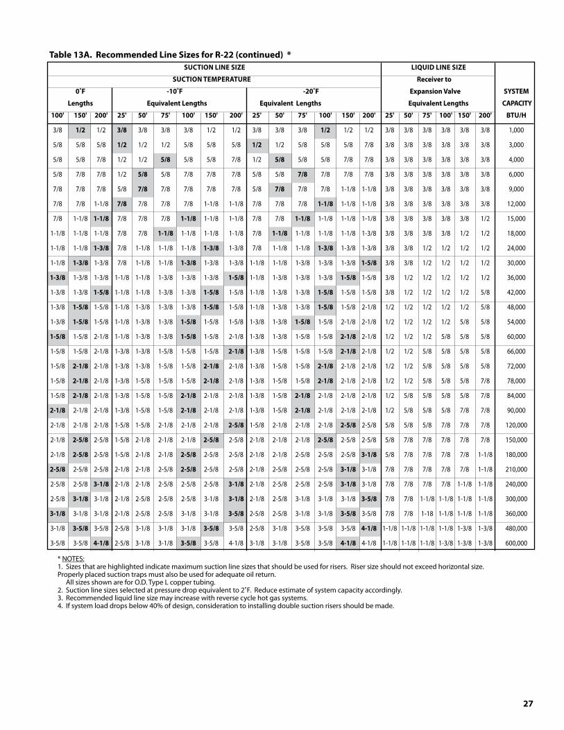
27
Table1�A.RecommendedLineSizesforR-22(continued)* SUCTIONLINESIZE LIQUIDLINESIZE
SUCTIONTEMPERATURE Receiverto
0˚F -10˚F -20˚F ExpansionValve SYSTEM
Lengths EquivalentLengths EquivalentLengths EquivalentLengths CAPACITY
100' 150' 200' 25' 50' 75' 100' 150' 200' 25' 50' 75' 100' 150' 200' 25' 50' 75' 100' 150' 200' BTU/H
3/8 1/2 1/2 �/8 3/8 3/8 3/8 1/2 1/2 3/8 3/8 3/8 1/2 1/2 1/2 3/8 3/8 3/8 3/8 3/8 3/8 1,000
5/8 5/8 5/8 1/2 1/2 1/2 5/8 5/8 5/8 1/2 1/2 5/8 5/8 5/8 7/8 3/8 3/8 3/8 3/8 3/8 3/8 3,000
5/8 5/8 7/8 1/2 1/2 5/8 5/8 5/8 7/8 1/2 5/8 5/8 5/8 7/8 7/8 3/8 3/8 3/8 3/8 3/8 3/8 4,000
5/8 7/8 7/8 1/2 5/8 5/8 7/8 7/8 7/8 5/8 5/8 7/8 7/8 7/8 7/8 3/8 3/8 3/8 3/8 3/8 3/8 6,000
7/8 7/8 7/8 5/8 7/8 7/8 7/8 7/8 7/8 5/8 7/8 7/8 7/8 1-1/8 1-1/8 3/8 3/8 3/8 3/8 3/8 3/8 9,000
7/8 7/8 1-1/8 7/8 7/8 7/8 7/8 1-1/8 1-1/8 7/8 7/8 7/8 1-1/8 1-1/8 1-1/8 3/8 3/8 3/8 3/8 3/8 3/8 12,000
7/8 1-1/8 1-1/8 7/8 7/8 7/8 1-1/8 1-1/8 1-1/8 7/8 7/8 1-1/8 1-1/8 1-1/8 1-1/8 3/8 3/8 3/8 3/8 3/8 1/2 15,000
1-1/8 1-1/8 1-1/8 7/8 7/8 1-1/8 1-1/8 1-1/8 1-1/8 7/8 1-1/8 1-1/8 1-1/8 1-1/8 1-3/8 3/8 3/8 3/8 3/8 1/2 1/2 18,000
1-1/8 1-1/8 1-�/8 7/8 1-1/8 1-1/8 1-1/8 1-�/8 1-3/8 7/8 1-1/8 1-1/8 1-�/8 1-3/8 1-3/8 3/8 3/8 1/2 1/2 1/2 1/2 24,000
1-1/8 1-�/8 1-3/8 7/8 1-1/8 1-1/8 1-�/8 1-3/8 1-3/8 1-1/8 1-1/8 1-3/8 1-3/8 1-3/8 1-5/8 3/8 3/8 1/2 1/2 1/2 1/2 30,000
1-�/8 1-3/8 1-3/8 1-1/8 1-1/8 1-3/8 1-3/8 1-3/8 1-5/8 1-1/8 1-3/8 1-3/8 1-3/8 1-5/8 1-5/8 3/8 1/2 1/2 1/2 1/2 1/2 36,000
1-3/8 1-3/8 1-5/8 1-1/8 1-1/8 1-3/8 1-3/8 1-5/8 1-5/8 1-1/8 1-3/8 1-3/8 1-5/8 1-5/8 1-5/8 3/8 1/2 1/2 1/2 1/2 5/8 42,000
1-3/8 1-5/8 1-5/8 1-1/8 1-3/8 1-3/8 1-3/8 1-5/8 1-5/8 1-1/8 1-3/8 1-3/8 1-5/8 1-5/8 2-1/8 1/2 1/2 1/2 1/2 1/2 5/8 48,000
1-3/8 1-5/8 1-5/8 1-1/8 1-3/8 1-3/8 1-5/8 1-5/8 1-5/8 1-3/8 1-3/8 1-5/8 1-5/8 2-1/8 2-1/8 1/2 1/2 1/2 1/2 5/8 5/8 54,000
1-5/8 1-5/8 2-1/8 1-1/8 1-3/8 1-3/8 1-5/8 1-5/8 2-1/8 1-3/8 1-3/8 1-5/8 1-5/8 2-1/8 2-1/8 1/2 1/2 1/2 5/8 5/8 5/8 60,000
1-5/8 1-5/8 2-1/8 1-3/8 1-3/8 1-5/8 1-5/8 1-5/8 2-1/8 1-3/8 1-5/8 1-5/8 1-5/8 2-1/8 2-1/8 1/2 1/2 5/8 5/8 5/8 5/8 66,000
1-5/8 2-1/8 2-1/8 1-3/8 1-3/8 1-5/8 1-5/8 2-1/8 2-1/8 1-3/8 1-5/8 1-5/8 2-1/8 2-1/8 2-1/8 1/2 1/2 5/8 5/8 5/8 5/8 72,000
1-5/8 2-1/8 2-1/8 1-3/8 1-5/8 1-5/8 1-5/8 2-1/8 2-1/8 1-3/8 1-5/8 1-5/8 2-1/8 2-1/8 2-1/8 1/2 1/2 5/8 5/8 5/8 7/8 78,000
1-5/8 2-1/8 2-1/8 1-3/8 1-5/8 1-5/8 2-1/8 2-1/8 2-1/8 1-3/8 1-5/8 2-1/8 2-1/8 2-1/8 2-1/8 1/2 5/8 5/8 5/8 5/8 7/8 84,000
2-1/8 2-1/8 2-1/8 1-3/8 1-5/8 1-5/8 2-1/8 2-1/8 2-1/8 1-3/8 1-5/8 2-1/8 2-1/8 2-1/8 2-1/8 1/2 5/8 5/8 5/8 7/8 7/8 90,000
2-1/8 2-1/8 2-1/8 1-5/8 1-5/8 2-1/8 2-1/8 2-1/8 2-5/8 1-5/8 2-1/8 2-1/8 2-1/8 2-5/8 2-5/8 5/8 5/8 5/8 7/8 7/8 7/8 120,000
2-1/8 2-5/8 2-5/8 1-5/8 2-1/8 2-1/8 2-1/8 2-5/8 2-5/8 2-1/8 2-1/8 2-1/8 2-5/8 2-5/8 2-5/8 5/8 7/8 7/8 7/8 7/8 7/8 150,000
2-1/8 2-5/8 2-5/8 1-5/8 2-1/8 2-1/8 2-5/8 2-5/8 2-5/8 2-1/8 2-1/8 2-5/8 2-5/8 2-5/8 �-1/8 5/8 7/8 7/8 7/8 7/8 1-1/8 180,000
2-5/8 2-5/8 2-5/8 2-1/8 2-1/8 2-5/8 2-5/8 2-5/8 2-5/8 2-1/8 2-5/8 2-5/8 2-5/8 �-1/8 3-1/8 7/8 7/8 7/8 7/8 7/8 1-1/8 210,000
2-5/8 2-5/8 �-1/8 2-1/8 2-1/8 2-5/8 2-5/8 2-5/8 �-1/8 2-1/8 2-5/8 2-5/8 2-5/8 �-1/8 3-1/8 7/8 7/8 7/8 7/8 1-1/8 1-1/8 240,000
2-5/8 �-1/8 3-1/8 2-1/8 2-5/8 2-5/8 2-5/8 3-1/8 �-1/8 2-1/8 2-5/8 3-1/8 3-1/8 3-1/8 �-5/8 7/8 7/8 1-1/8 1-1/8 1-1/8 1-1/8 300,000
�-1/8 3-1/8 3-1/8 2-1/8 2-5/8 2-5/8 3-1/8 3-1/8 �-5/8 2-5/8 2-5/8 3-1/8 3-1/8 �-5/8 3-5/8 7/8 7/8 1-18 1-1/8 1-1/8 1-1/8 360,000
3-1/8 �-5/8 3-5/8 2-5/8 3-1/8 3-1/8 3-1/8 �-5/8 3-5/8 2-5/8 3-1/8 3-5/8 3-5/8 3-5/8 4-1/8 1-1/8 1-1/8 1-1/8 1-1/8 1-3/8 1-3/8 480,000
3-5/8 3-5/8 4-1/8 2-5/8 3-1/8 3-1/8 �-5/8 3-5/8 4-1/8 3-1/8 3-1/8 3-5/8 3-5/8 4-1/8 4-1/8 1-1/8 1-1/8 1-1/8 1-3/8 1-3/8 1-3/8 600,000
* NOTES: 1. Sizes that are highlighted indicate maximum suction line sizes that should be used for risers. Riser size should not exceed horizontal size. Properly placed suction traps must also be used for adequate oil return. All sizes shown are for O.D. Type L copper tubing. 2. Suction line sizes selected at pressure drop equivalent to 2˚F. Reduce estimate of system capacity accordingly. 3. Recommended liquid line size may increase with reverse cycle hot gas systems. 4. If system load drops below 40% of design, consideration to installing double suction risers should be made.
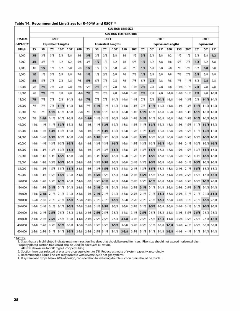
28
Table14.RecommendedLineSizesforR-404AandR507* SUCTIONLINESIZE
SUCTIONTEMPERATURE
SYSTEM +20˚F +10˚F -10˚F -20˚F
CAPACITY EquivalentLengths EquivalentLengths EquivalentLengths Equivalent
BTU/H 25' 50' 75' 100' 150' 200' 25' 50' 75' 100' 150' 200' 25' 50' 75' 100' 150' 200' 25' 50' 75'
1,000 �/8 3/8 3/8 3/8 3/8 3/8 �/8 3/8 3/8 3/8 3/8 1/2 �/8 3/8 3/8 1/2 1/2 1/2 3/8 3/8 1/2
3,000 �/8 3/8 1/2 1/2 1/2 5/8 3/8 1/2 1/2 1/2 5/8 5/8 1/2 1/2 5/8 5/8 5/8 7/8 1/2 1/2 5/8
4,000 3/8 1/2 1/2 1/2 5/8 5/8 1/2 1/2 1/2 5/8 5/8 7/8 1/2 5/8 5/8 5/8 7/8 7/8 1/2 5/8 5/8
6,000 1/2 1/2 5/8 5/8 7/8 7/8 1/2 1/2 5/8 5/8 7/8 7/8 1/2 5/8 5/8 7/8 7/8 7/8 5/8 5/8 7/8
9,000 5/8 5/8 7/8 7/8 7/8 7/8 5/8 5/8 7/8 7/8 7/8 7/8 5/8 7/8 7/8 7/8 7/8 1-1/8 5/8 7/8 7/8
12,000 5/8 7/8 7/8 7/8 7/8 7/8 5/8 7/8 7/8 7/8 7/8 1-1/8 7/8 7/8 7/8 7/8 1-1/8 1-1/8 7/8 7/8 7/8
15,000 5/8 7/8 7/8 7/8 7/8 1-1/8 7/8 7/8 7/8 7/8 1-1/8 1-1/8 7/8 7/8 7/8 1-1/8 1-1/8 1-1/8 7/8 7/8 1-1/8
18,000 7/8 7/8 7/8 7/8 1-1/8 1-1/8 7/8 7/8 7/8 1-1/8 1-1/8 1-1/8 7/8 7/8 1-1/8 1-1/8 1-1/8 1-3/8 7/8 1-1/8 1-1/8
24,000 7/8 7/8 7/8 1-1/8 1-1/8 1-1/8 7/8 1-1/8 1-1/8 1-1/8 1-1/8 1-3/8 7/8 1-1/8 1-1/8 1-1/8 1-3/8 1-3/8 1-1/8 1-1/8 1-1/8
30,000 7/8 7/8 1-1/8 1-1/8 1-1/8 1-3/8 7/8 1-1/8 1-1/8 1-1/8 1-3/8 1-3/8 1-1/8 1-1/8 1-1/8 1-3/8 1-3/8 1-3/8 1-1/8 1-1/8 1-1/8
36,000 7/8 1-1/8 1-1/8 1-1/8 1-3/8 1-3/8 1-1/8 1-1/8 1-1/8 1-3/8 1-3/8 1-3/8 1-1/8 1-1/8 1-3/8 1-3/8 1-3/8 1-5/8 1-1/8 1-1/8 1-3/8
42,000 1-1/8 1-1/8 1-1/8 1-�/8 1-3/8 1-3/8 1-1/8 1-1/8 1-�/8 1-3/8 1-3/8 1-5/8 1-1/8 1-�/8 1-3/8 1-3/8 1-5/8 1-5/8 1-1/8 1-�/8 1-3/8
48,000 1-1/8 1-1/8 1-�/8 1-3/8 1-3/8 1-3/8 1-1/8 1-1/8 1-�/8 1-3/8 1-5/8 1-5/8 1-1/8 1-�/8 1-3/8 1-3/8 1-5/8 1-5/8 1-1/8 1-�/8 1-3/8
54,000 1-1/8 1-1/8 1-�/8 1-3/8 1-3/8 1-5/8 1-1/8 1-�/8 1-3/8 1-3/8 1-5/8 1-5/8 1-�/8 1-3/8 1-3/8 1-5/8 1-5/8 1-5/8 1-3/8 1-�/8 1-5/8
60,000 1-1/8 1-1/8 1-3/8 1-3/8 1-5/8 1-5/8 1-1/8 1-3/8 1-3/8 1-5/8 1-5/8 1-5/8 1-3/8 1-3/8 1-5/8 1-5/8 1-5/8 2-1/8 1-3/8 1-3/8 1-5/8
66,000 1-1/8 1-3/8 1-3/8 1-3/8 1-5/8 1-5/8 1-1/8 1-3/8 1-3/8 1-5/8 1-5/8 1-5/8 1-3/8 1-5/8 1-5/8 1-5/8 1-5/8 1-5/8 1-3/8 1-5/8 1-5/8
72,000 1-1/8 1-3/8 1-3/8 1-5/8 1-5/8 1-5/8 1-1/8 1-3/8 1-5/8 1-5/8 1-5/8 1-5/8 1-3/8 1-5/8 1-5/8 1-5/8 1-5/8 1-5/8 1-3/8 1-5/8 1-5/8
78,000 1-1/8 1-3/8 1-3/8 1-5/8 1-5/8 2-1/8 1-3/8 1-3/8 1-5/8 1-5/8 1-5/8 2-1/8 1-3/8 1-5/8 1-5/8 1-5/8 1-5/8 2-1/8 1-5/8 1-5/8 1-5/8
84,000 1-1/8 1-3/8 1-5/8 1-5/8 1-5/8 2-1/8 1-3/8 1-3/8 1-5/8 1-5/8 2-1/8 2-1/8 1-3/8 1-5/8 1-5/8 1-5/8 2-1/8 2-1/8 1-5/8 1-5/8 1-5/8
90,000 1-3/8 1-3/8 1-5/8 1-5/8 2-1/8 2-1/8 1-3/8 1-5/8 1-5/8 1-5/8 2-1/8 2-1/8 1-5/8 1-5/8 1-5/8 2-1/8 2-1/8 2-5/8 1-5/8 1-5/8 2-1/8
120,000 1-3/8 1-5/8 1-5/8 2-1/8 2-1/8 2-1/8 1-3/8 1-5/8 2-1/8 2-1/8 2-1/8 2-1/8 1-5/8 2-1/8 2-1/8 2-1/8 2-5/8 2-5/8 1-5/8 2-1/8 2-1/8
150,000 1-5/8 1-5/8 2-1/8 2-1/8 2-1/8 2-1/8 1-5/8 2-1/8 2-1/8 2-1/8 2-1/8 2-5/8 2-1/8 2-1/8 2-1/8 2-5/8 2-5/8 2-5/8 2-1/8 2-1/8 2-1/8
180,000 1-5/8 2-1/8 2-1/8 2-1/8 2-1/8 2-5/8 1-5/8 2-1/8 2-1/8 2-1/8 2-5/8 2-5/8 2-1/8 2-1/8 2-5/8 2-5/8 2-5/8 3-1/8 2-1/8 2-1/8 2-5/8
210,000 1-5/8 2-1/8 2-1/8 2-1/8 2-5/8 2-5/8 2-1/8 2-1/8 2-1/8 2-5/8 2-5/8 2-5/8 2-1/8 2-1/8 2-5/8 2-5/8 3-1/8 3-1/8 2-1/8 2-5/8 2-5/8
240,000 1-5/8 2-1/8 2-1/8 2-1/8 2-5/8 2-5/8 2-1/8 2-1/8 2-5/8 2-5/8 2-5/8 2-5/8 2-1/8 2-5/8 2-5/8 2-5/8 3-1/8 3-1/8 2-1/8 2-5/8 2-5/8
300,000 2-1/8 2-1/8 2-5/8 2-5/8 2-5/8 3-1/8 2-1/8 2-5/8 2-5/8 2-5/8 3-1/8 3-1/8 2-5/8 2-5/8 2-5/8 3-1/8 3-1/8 3-5/8 2-5/8 2-5/8 2-5/8
360,000 2-1/8 2-1/8 2-5/8 2-5/8 3-1/8 3-1/8 2-1/8 2-5/8 2-5/8 2-5/8 �-1/8 3-1/8 2-5/8 2-5/8 �-1/8 3-1/8 3-5/8 3-5/8 2-5/8 2-5/8 �-1/8
480,000 2-1/8 2-5/8 2-5/8 �-1/8 3-1/8 3-5/8 2-5/8 2-5/8 2-5/8 2-5/8 3-5/8 3-5/8 2-5/8 3-1/8 3-1/8 �-5/8 3-5/8 4-1/8 2-5/8 3-1/8 3-1/8
600,000 2-5/8 2-5/8 3-1/8 3-1/8 �-5/8 3-5/8 2-5/8 2-5/8 3-1/8 3-1/8 �-5/8 3-5/8 3-1/8 3-1/8 3-1/8 �-5/8 4-1/8 4-1/8 3-1/8 3-1/8 3-1/8 * NOTES: 1. Sizes that are highlighted indicate maximum suction line sizes that should be used for risers. Riser size should not exceed horizontal size. Properly placed suction traps must also be used for adequate oil return. All sizes shown are for O.D. Type L copper tubing. 2. Suction line sizes selected at pressure drop equivalent to 2˚F. Reduce estimate of system capacity accordingly. 3. Recommended liquid line size may increase with reverse cycle hot gas systems. 4. If system load drops below 40% of design, consideration to installing double suction risers should be made.
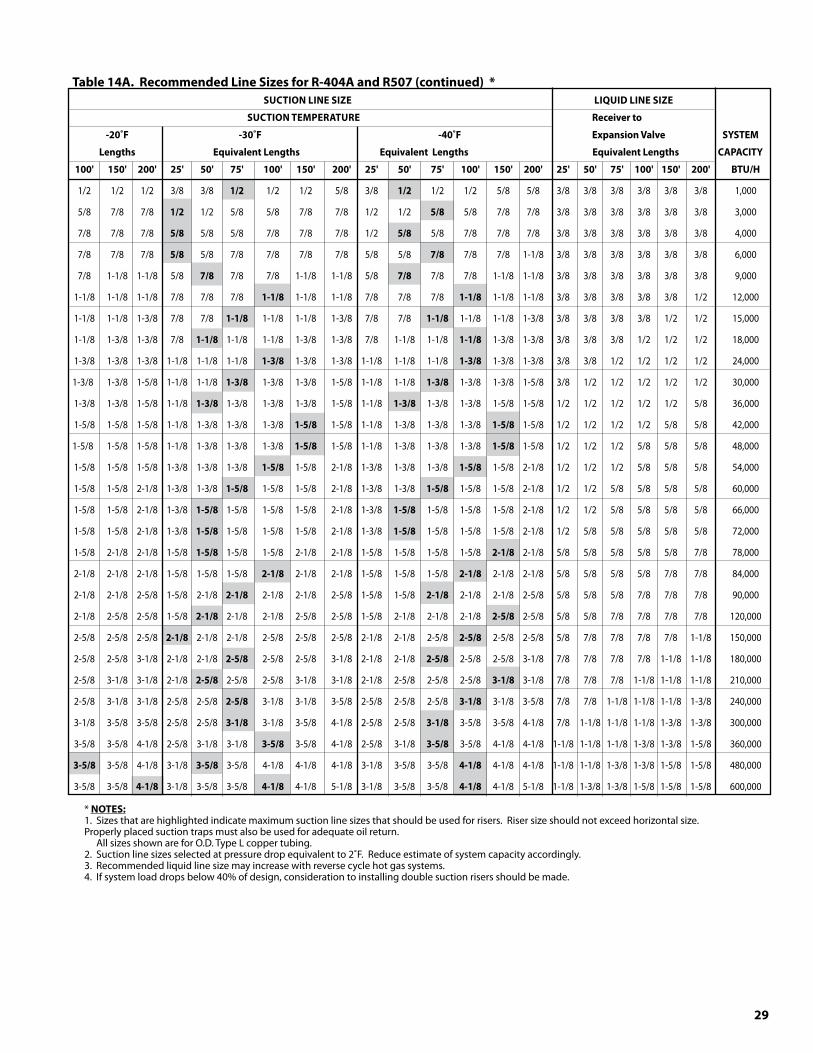
29
Table14A.RecommendedLineSizesforR-404AandR507(continued)* SUCTIONLINESIZE LIQUIDLINESIZE
SUCTIONTEMPERATURE Receiverto
-20˚F -�0˚F -40˚F ExpansionValveSYSTEM
Lengths EquivalentLengths EquivalentLengths EquivalentLengthsCAPACITY
100' 150' 200' 25' 50' 75' 100' 150' 200' 25' 50' 75' 100' 150' 200' 25' 50' 75' 100' 150' 200' BTU/H
1/2 1/2 1/2 3/8 3/8 1/2 1/2 1/2 5/8 3/8 1/2 1/2 1/2 5/8 5/8 3/8 3/8 3/8 3/8 3/8 3/8 1,000
5/8 7/8 7/8 1/2 1/2 5/8 5/8 7/8 7/8 1/2 1/2 5/8 5/8 7/8 7/8 3/8 3/8 3/8 3/8 3/8 3/8 3,000
7/8 7/8 7/8 5/8 5/8 5/8 7/8 7/8 7/8 1/2 5/8 5/8 7/8 7/8 7/8 3/8 3/8 3/8 3/8 3/8 3/8 4,000
7/8 7/8 7/8 5/8 5/8 7/8 7/8 7/8 7/8 5/8 5/8 7/8 7/8 7/8 1-1/8 3/8 3/8 3/8 3/8 3/8 3/8 6,000
7/8 1-1/8 1-1/8 5/8 7/8 7/8 7/8 1-1/8 1-1/8 5/8 7/8 7/8 7/8 1-1/8 1-1/8 3/8 3/8 3/8 3/8 3/8 3/8 9,000
1-1/8 1-1/8 1-1/8 7/8 7/8 7/8 1-1/8 1-1/8 1-1/8 7/8 7/8 7/8 1-1/8 1-1/8 1-1/8 3/8 3/8 3/8 3/8 3/8 1/2 12,000
1-1/8 1-1/8 1-3/8 7/8 7/8 1-1/8 1-1/8 1-1/8 1-3/8 7/8 7/8 1-1/8 1-1/8 1-1/8 1-3/8 3/8 3/8 3/8 3/8 1/2 1/2 15,000
1-1/8 1-3/8 1-3/8 7/8 1-1/8 1-1/8 1-1/8 1-3/8 1-3/8 7/8 1-1/8 1-1/8 1-1/8 1-3/8 1-3/8 3/8 3/8 3/8 1/2 1/2 1/2 18,000
1-3/8 1-3/8 1-3/8 1-1/8 1-1/8 1-1/8 1-�/8 1-3/8 1-3/8 1-1/8 1-1/8 1-1/8 1-�/8 1-3/8 1-3/8 3/8 3/8 1/2 1/2 1/2 1/2 24,000
1-3/8 1-3/8 1-5/8 1-1/8 1-1/8 1-�/8 1-3/8 1-3/8 1-5/8 1-1/8 1-1/8 1-�/8 1-3/8 1-3/8 1-5/8 3/8 1/2 1/2 1/2 1/2 1/2 30,000
1-3/8 1-3/8 1-5/8 1-1/8 1-�/8 1-3/8 1-3/8 1-3/8 1-5/8 1-1/8 1-�/8 1-3/8 1-3/8 1-5/8 1-5/8 1/2 1/2 1/2 1/2 1/2 5/8 36,000
1-5/8 1-5/8 1-5/8 1-1/8 1-3/8 1-3/8 1-3/8 1-5/8 1-5/8 1-1/8 1-3/8 1-3/8 1-3/8 1-5/8 1-5/8 1/2 1/2 1/2 1/2 5/8 5/8 42,000
1-5/8 1-5/8 1-5/8 1-1/8 1-3/8 1-3/8 1-3/8 1-5/8 1-5/8 1-1/8 1-3/8 1-3/8 1-3/8 1-5/8 1-5/8 1/2 1/2 1/2 5/8 5/8 5/8 48,000
1-5/8 1-5/8 1-5/8 1-3/8 1-3/8 1-3/8 1-5/8 1-5/8 2-1/8 1-3/8 1-3/8 1-3/8 1-5/8 1-5/8 2-1/8 1/2 1/2 1/2 5/8 5/8 5/8 54,000
1-5/8 1-5/8 2-1/8 1-3/8 1-3/8 1-5/8 1-5/8 1-5/8 2-1/8 1-3/8 1-3/8 1-5/8 1-5/8 1-5/8 2-1/8 1/2 1/2 5/8 5/8 5/8 5/8 60,000
1-5/8 1-5/8 2-1/8 1-3/8 1-5/8 1-5/8 1-5/8 1-5/8 2-1/8 1-3/8 1-5/8 1-5/8 1-5/8 1-5/8 2-1/8 1/2 1/2 5/8 5/8 5/8 5/8 66,000
1-5/8 1-5/8 2-1/8 1-3/8 1-5/8 1-5/8 1-5/8 1-5/8 2-1/8 1-3/8 1-5/8 1-5/8 1-5/8 1-5/8 2-1/8 1/2 5/8 5/8 5/8 5/8 5/8 72,000
1-5/8 2-1/8 2-1/8 1-5/8 1-5/8 1-5/8 1-5/8 2-1/8 2-1/8 1-5/8 1-5/8 1-5/8 1-5/8 2-1/8 2-1/8 5/8 5/8 5/8 5/8 5/8 7/8 78,000
2-1/8 2-1/8 2-1/8 1-5/8 1-5/8 1-5/8 2-1/8 2-1/8 2-1/8 1-5/8 1-5/8 1-5/8 2-1/8 2-1/8 2-1/8 5/8 5/8 5/8 5/8 7/8 7/8 84,000
2-1/8 2-1/8 2-5/8 1-5/8 2-1/8 2-1/8 2-1/8 2-1/8 2-5/8 1-5/8 1-5/8 2-1/8 2-1/8 2-1/8 2-5/8 5/8 5/8 5/8 7/8 7/8 7/8 90,000
2-1/8 2-5/8 2-5/8 1-5/8 2-1/8 2-1/8 2-1/8 2-5/8 2-5/8 1-5/8 2-1/8 2-1/8 2-1/8 2-5/8 2-5/8 5/8 5/8 7/8 7/8 7/8 7/8 120,000
2-5/8 2-5/8 2-5/8 2-1/8 2-1/8 2-1/8 2-5/8 2-5/8 2-5/8 2-1/8 2-1/8 2-5/8 2-5/8 2-5/8 2-5/8 5/8 7/8 7/8 7/8 7/8 1-1/8 150,000
2-5/8 2-5/8 3-1/8 2-1/8 2-1/8 2-5/8 2-5/8 2-5/8 3-1/8 2-1/8 2-1/8 2-5/8 2-5/8 2-5/8 3-1/8 7/8 7/8 7/8 7/8 1-1/8 1-1/8 180,000
2-5/8 3-1/8 3-1/8 2-1/8 2-5/8 2-5/8 2-5/8 3-1/8 3-1/8 2-1/8 2-5/8 2-5/8 2-5/8 �-1/8 3-1/8 7/8 7/8 7/8 1-1/8 1-1/8 1-1/8 210,000
2-5/8 3-1/8 3-1/8 2-5/8 2-5/8 2-5/8 3-1/8 3-1/8 3-5/8 2-5/8 2-5/8 2-5/8 �-1/8 3-1/8 3-5/8 7/8 7/8 1-1/8 1-1/8 1-1/8 1-3/8 240,000
3-1/8 3-5/8 3-5/8 2-5/8 2-5/8 �-1/8 3-1/8 3-5/8 4-1/8 2-5/8 2-5/8 �-1/8 3-5/8 3-5/8 4-1/8 7/8 1-1/8 1-1/8 1-1/8 1-3/8 1-3/8 300,000
3-5/8 3-5/8 4-1/8 2-5/8 3-1/8 3-1/8 �-5/8 3-5/8 4-1/8 2-5/8 3-1/8 �-5/8 3-5/8 4-1/8 4-1/8 1-1/8 1-1/8 1-1/8 1-3/8 1-3/8 1-5/8 360,000
�-5/8 3-5/8 4-1/8 3-1/8 �-5/8 3-5/8 4-1/8 4-1/8 4-1/8 3-1/8 3-5/8 3-5/8 4-1/8 4-1/8 4-1/8 1-1/8 1-1/8 1-3/8 1-3/8 1-5/8 1-5/8 480,000
3-5/8 3-5/8 4-1/8 3-1/8 3-5/8 3-5/8 4-1/8 4-1/8 5-1/8 3-1/8 3-5/8 3-5/8 4-1/8 4-1/8 5-1/8 1-1/8 1-3/8 1-3/8 1-5/8 1-5/8 1-5/8 600,000 * NOTES: 1. Sizes that are highlighted indicate maximum suction line sizes that should be used for risers. Riser size should not exceed horizontal size. Properly placed suction traps must also be used for adequate oil return. All sizes shown are for O.D. Type L copper tubing. 2. Suction line sizes selected at pressure drop equivalent to 2˚F. Reduce estimate of system capacity accordingly. 3. Recommended liquid line size may increase with reverse cycle hot gas systems. 4. If system load drops below 40% of design, consideration to installing double suction risers should be made.
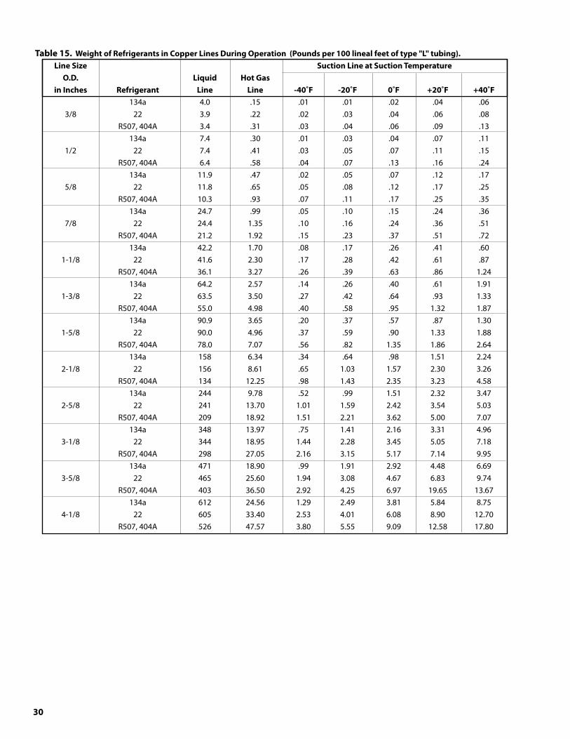
�0
Table15.WeightofRefrigerantsinCopperLinesDuringOperation(Poundsper100linealfeetoftype"L"tubing). LineSize SuctionLineatSuctionTemperature O.D. Liquid HotGas inInches Refrigerant Line Line -40˚F -20˚F 0˚F +20˚F +40˚F 134a 4.0 .15 .01 .01 .02 .04 .06 3/8 22 3.9 .22 .02 .03 .04 .06 .08 R507, 404A 3.4 .31 .03 .04 .06 .09 .13 134a 7.4 .30 .01 .03 .04 .07 .11 1/2 22 7.4 .41 .03 .05 .07 .11 .15 R507, 404A 6.4 .58 .04 .07 .13 .16 .24 134a 11.9 .47 .02 .05 .07 .12 .17 5/8 22 11.8 .65 .05 .08 .12 .17 .25 R507, 404A 10.3 .93 .07 .11 .17 .25 .35 134a 24.7 .99 .05 .10 .15 .24 .36 7/8 22 24.4 1.35 .10 .16 .24 .36 .51 R507, 404A 21.2 1.92 .15 .23 .37 .51 .72 134a 42.2 1.70 .08 .17 .26 .41 .60 1-1/8 22 41.6 2.30 .17 .28 .42 .61 .87 R507, 404A 36.1 3.27 .26 .39 .63 .86 1.24 134a 64.2 2.57 .14 .26 .40 .61 1.91 1-3/8 22 63.5 3.50 .27 .42 .64 .93 1.33 R507, 404A 55.0 4.98 .40 .58 .95 1.32 1.87 134a 90.9 3.65 .20 .37 .57 .87 1.30 1-5/8 22 90.0 4.96 .37 .59 .90 1.33 1.88 R507, 404A 78.0 7.07 .56 .82 1.35 1.86 2.64 134a 158 6.34 .34 .64 .98 1.51 2.24 2-1/8 22 156 8.61 .65 1.03 1.57 2.30 3.26 R507, 404A 134 12.25 .98 1.43 2.35 3.23 4.58 134a 244 9.78 .52 .99 1.51 2.32 3.47 2-5/8 22 241 13.70 1.01 1.59 2.42 3.54 5.03 R507, 404A 209 18.92 1.51 2.21 3.62 5.00 7.07 134a 348 13.97 .75 1.41 2.16 3.31 4.96 3-1/8 22 344 18.95 1.44 2.28 3.45 5.05 7.18 R507, 404A 298 27.05 2.16 3.15 5.17 7.14 9.95 134a 471 18.90 .99 1.91 2.92 4.48 6.69 3-5/8 22 465 25.60 1.94 3.08 4.67 6.83 9.74 R507, 404A 403 36.50 2.92 4.25 6.97 19.65 13.67 134a 612 24.56 1.29 2.49 3.81 5.84 8.75 4-1/8 22 605 33.40 2.53 4.01 6.08 8.90 12.70 R507, 404A 526 47.57 3.80 5.55 9.09 12.58 17.80
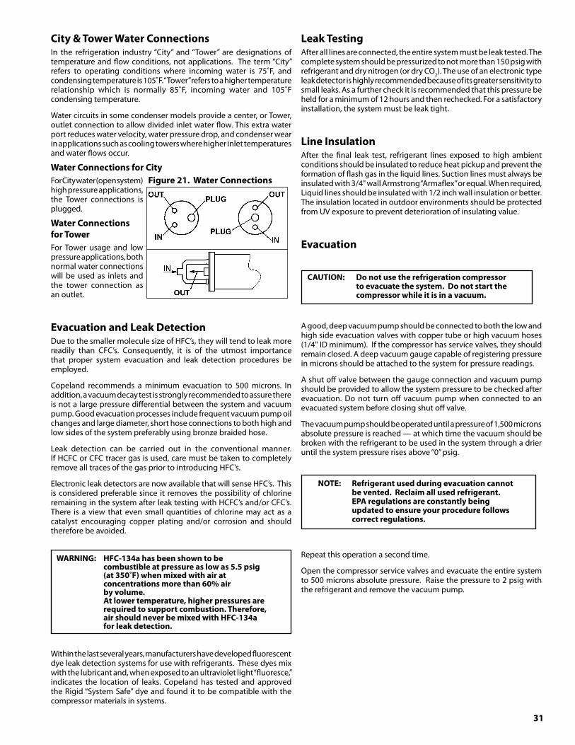
�1
WARNING: HFC-1�4ahasbeenshowntobe combustibleatpressureaslowas5.5psig (at�50˚F)whenmixedwithairat
concentrationsmorethan60%air byvolume. Atlowertemperature,higherpressuresare
requiredtosupportcombustion.Therefore, airshouldneverbemixedwithHFC-1�4a forleakdetection.
City&TowerWaterConnectionsIn the refrigeration industry “City” and “Tower” are designations of temperature and flow conditions, not applications. The term “City” refers to operating conditions where incoming water is 75˚F, and condensing temperature is 105˚F. “Tower” refers to a higher temperature relationship which is normally 85˚F, incoming water and 105˚F condensing temperature.
Water circuits in some condenser models provide a center, or Tower, outlet connection to allow divided inlet water flow. This extra water port reduces water velocity, water pressure drop, and condenser wear in applications such as cooling towers where higher inlet temperatures and water flows occur.
WaterConnectionsforCityFor City water (open system) high pressure applications, the Tower connections is plugged.
WaterConnectionsforTowerFor Tower usage and low pressure applications, both normal water connections will be used as inlets and the tower connection as an outlet.
EvacuationandLeakDetectionDue to the smaller molecule size of HFC’s, they will tend to leak more readily than CFC’s. Consequently, it is of the utmost importance that proper system evacuation and leak detection procedures be employed.
Copeland recommends a minimum evacuation to 500 microns. In addition, a vacuum decay test is strongly recommended to assure there is not a large pressure differential between the system and vacuum pump. Good evacuation processes include frequent vacuum pump oil changes and large diameter, short hose connections to both high and low sides of the system preferably using bronze braided hose.
Leak detection can be carried out in the conventional manner. If HCFC or CFC tracer gas is used, care must be taken to completely remove all traces of the gas prior to introducing HFC’s.
Electronic leak detectors are now available that will sense HFC’s. This is considered preferable since it removes the possibility of chlorine remaining in the system after leak testing with HCFC’s and/or CFC’s. There is a view that even small quantities of chlorine may act as a catalyst encouraging copper plating and/or corrosion and should therefore be avoided.
Within the last several years, manufacturers have developed fluorescent dye leak detection systems for use with refrigerants. These dyes mix with the lubricant and, when exposed to an ultraviolet light “fluoresce,” indicates the location of leaks. Copeland has tested and approved the Rigid “System Safe” dye and found it to be compatible with the compressor materials in systems.
LeakTestingAfter all lines are connected, the entire system must be leak tested. The complete system should be pressurized to not more than 150 psig with refrigerant and dry nitrogen (or dry CO2). The use of an electronic type leak detector is highly recommended because of its greater sensitivity to small leaks. As a further check it is recommended that this pressure be held for a minimum of 12 hours and then rechecked. For a satisfactory installation, the system must be leak tight.
LineInsulationAfter the final leak test, refrigerant lines exposed to high ambient conditions should be insulated to reduce heat pickup and prevent the formation of flash gas in the liquid lines. Suction lines must always be insulated with 3/4" wall Armstrong “Armaflex” or equal. When required, Liquid lines should be insulated with 1/2 inch wall insulation or better. The insulation located in outdoor environments should be protected from UV exposure to prevent deterioration of insulating value.
Evacuation
CAUTION: Donotusetherefrigerationcompressor toevacuatethesystem.Donotstartthe compressorwhileitisinavacuum.
A good, deep vacuum pump should be connected to both the low and high side evacuation valves with copper tube or high vacuum hoses (1/4" ID minimum). If the compressor has service valves, they should remain closed. A deep vacuum gauge capable of registering pressure in microns should be attached to the system for pressure readings.
A shut off valve between the gauge connection and vacuum pump should be provided to allow the system pressure to be checked after evacuation. Do not turn off vacuum pump when connected to an evacuated system before closing shut off valve.
The vacuum pump should be operated until a pressure of 1,500 microns absolute pressure is reached — at which time the vacuum should be broken with the refrigerant to be used in the system through a drier until the system pressure rises above “0” psig.
NOTE: Refrigerantusedduringevacuationcannotbevented.Reclaimallusedrefrigerant.
EPAregulationsareconstantlybeingupdatedtoensureyourprocedurefollowscorrectregulations.
Repeat this operation a second time.
Open the compressor service valves and evacuate the entire system to 500 microns absolute pressure. Raise the pressure to 2 psig with the refrigerant and remove the vacuum pump.
Figure21.WaterConnections
�2
CheckOutandStartUp
After the installation has been completed, the following points should be covered before the system is placed in operation:
(a) Check all electrical and refrigerant connections. Be sure they are all tight. (b) Observe compressor oil level before start-up. The oil level should be at or slightly above the 1/4 level of the sight glass. Refer to Table 8 on page 16 for proper compressor oil. (c) Remove upper mounting nuts on the compressor feet. Remove the shipping spacers. Install the neoprene washers onto the compressor feet. Replace the upper mounting nuts and washers, allowing 1/16" space between the mounting nut and the neoprene spacer. (d) Check high and low pressure controls, pressure regulating valves, oil pressure safety controls, and all other safety controls, and adjust if necessary. (e) Check the room thermostat for normal operation and adjust. (f ) Wiring diagrams, instruction bulletins, etc. attached to the condensing units should be read and filed for future reference. (g) All fan motors on air cooled condensers, evaporators, etc. should be checked for proper rotation. Fan motor mounts should be carefully checked for tightness and proper alignment. (h) Electric and hot gas evaporator fan motors should be temporarily wired for continuous operation until the room temperature has stabilized. (i) Observe system pressures during charging and initial operation. Do not add oil while the system is short of refrigerant unless oil level is dangerously low. (j) Continue charging until system has sufficient refrigerant for proper operation. Do not overcharge. Remember that bubbles in a sight glass may be caused by a restriction as well as a shortage of refrigerant. (k) Do not leave unit unattended until the system has reached normal operating conditions and the oil charge has been properly adjusted to maintain the oil level between 1/4 and bottom of the sight glass. (l) Make sure all Schrader valve caps are in place and tight
CAUTION:Extremecaremustbetakeninstarting compressorsforthefirsttimeaftersystem charging.Atthistime,alloftheoilandmost oftherefrigerantmightbeinthecompressor creatingaconditionwhichcouldcause compressordamageduetoslugging. Activatingthecrankcaseheaterfor24hours priortostart-upisrequired.Ifnocrankcase heaterispresent,thendirectinga500watt heatlamporothersafeheatsourceonthe lowershellofthecompressorforapproximately thirtyminuteswillbebeneficialineliminating thisconditionwhichmightneverreoccur.
WARNING:Scrollcompressorisdirectional dependent.Ifnoisy,changephaseofinput wiring.
RefrigerantChargingInstructions
1. Install a liquid line drier in the refrigerant supply line between the service gauge and the liquid service port of the receiver. This extra drier will insure that all refrigerant supplied to the system is clean and dry.
2. When initially charging a system that is in a vacuum, liquid refrigerant can be added directly into the receiver tank.
3. Check equipment catalog for refrigerant capacity. System refrigerant capacity is 90% of receiver capacity. Do not add more refrigerant than the data tag indicates, unless the line run exceeds 25ft. Then, add additional refrigerant as per the chart on page 30. Weigh the refrigerant drum before charging so an accurate record can be kept of the weight of refrigerant put in the system.
4. Start the system and finish charging until the sight glass indicates a full charge and the proper amount has been weighed in. If the refrigerant must be added to the system through the suction side of the compressor, charge in vapor form only. Liquid charging must be done in the high side only or with liquid metering devices to protect the compressor.
LowHeadPressureSystems
If you are charging the system by using a clear sight glass as an indication of proper charge the following must be considered.
Check the condensing temperature. It must be above 105˚F. If not, it will be necessary to reduce the amount of air going through the condenser from fans still running. Simply reduce the effective condenser face area to raise the discharge pressure above the equivalent 105˚F condensing temperature and then proceed to charge to clear the sightglass. Adjust evaporator superheat at this time. Return to full condenser face area and allow the system to balance.
FieldWiring
WARNING: Allwiringmustbedoneinaccordancewithapplicablecodesandlocal ordinances.
The field wiring should enter the areas as provided on the unit. The wiring diagram for each unit is located on the inside of the electrical panel door. All field wiring should be done in a professional manner and in accordance with all governing codes. Before operating unit, double check all wiring connections, including the factory terminals. Factory connections can vibrate loose during shipment.
1. The serial data tag on the unit is marked with the electrical characteristic for wiring the unit.
2. Consult the wiring diagram in the unit cooler and in the con-densing unit for proper connections.
3. Wire type should be of copper conductor only and of the proper size to handle the connected load.
4. The unit must be grounded.5. For multiple evaporator systems, the defrost termination
controls should be wired in series. Follow the wiring diagrams for multiple evaporator systems carefully. This will assure com-plete defrost of all evaporators in the system.
6. Multiple evaporator systems should operate off of one thermo-stat.
7. If a remote defrost timer is to be used, the timer should be located outside the refrigerated space.
8. For air cooled condensers, due to multiple low amp motors, we recommend using time delay fuse protection instead of circuit breakers.
��
SystemBalancing-CompressorSuperheat
IMPORTANT: Inordertoobtainthemaximumcapacityfromasystem,andtoensuretrouble-freeopera-tion,itisnecessarytobalanceeachandeverysystem.
This is extremely important with any refrigeration system.
The critical value which must be checked is suction superheat.
Suction superheat should be checked at the compressor as follows:
1. Measure the suction pressure at the suction service valve of the compressor and determine the saturation temperature corresponding to this pressure from a “Temperature-Pressure” chart.
2. Measure the suction temperature of the suction line about one foot back from the compressor using an accurate thermometer.
3. Subtract the saturated temperature from the actual suction line temperature. The difference is superheat.
Too low a suction superheat can result in liquid being returned to the compressor. This will cause dilution of the oil and eventual failure of the bearings and rings or in the extreme case, valve failure.
Too high a suction superheat will result in excessive discharge temperatures which cause a break down of the oil and results in piston ring wear, piston and cylinder wall damage.
It should also be remembered that the system capacity decreases as the suction superheat increases. For maximum system capacity, suction superheat should be kept as low as is practical. Copeland mandates a minimum superheat of 20˚F atthecompressor. We recommend that the superheat atthecompressor be between 20˚F and 30˚F.
If adjustments to the suction superheat need to be made, the expansion valve at the evaporator should be adjusted. See instructions on page 34.
OperationalCheckOut
After the system has been charged and has operated for at least two hours at normal operating conditions without any indication of malfunction, it should be allowed to operate overnight on automatic controls. Then a thorough recheck of the entire system operation should be made as follows:
(a) Check compressor discharge and suction pressures. If not within system design limits, determine why and take corrective action.
(b) Check liquid line sight glass and expansion valve operation. If there are indications that more refrigerant is required, leak test all connections and system components and repair any leaks before adding refrigerant.
(c) Observe oil level in compressor crankcase sight glass. Add oil as necessary to bring level to bottom 1/4 of the sight glass.
(d) Thermostatic expansion valves must be checked for proper superheat settings. Feeler bulbs must be in positive contact with the suction line and should be insulated. Valves set at high superheat will lower refrigeration capacity. Low superheat promotes liquid slugging and compressor bearing washout.
(e) Using suitable instruments, carefully check line voltage and amperage at the compressor terminals. Voltage must be within 10% of that indicated on the condensing unit nameplate. If high or low voltage is indicated, notify the power company. If amperage
draw is excessive, immediately determine the cause and take corrective action. On three phase motor compressors, check to see that a balanced load is drawn by each phase.
(f ) The maximum approved settings for high pressure controls on our air cooled condensing equipment is 425 psig. On air cooled systems, check as follows: Disconnect the fan motors or block the condenser inlet air. Watch high pressure gauge for cutout point. Recheck all safety and operating controls for proper operation and adjust if necessary.
(g) Check defrost controls for initiation and termination settings, and length of defrost period. Set fail safe at length of defrost + 25%.
Example: 20 minute defrost + 5 minutes = 25 minute fail safe (h) Check drain pan for proper drainage.(i) Check winter head pressure controls for pressure
setting.(j) Check crankcase heater operation if used.(k) Install instruction card and control system diagram for
use of building manager or owner.
NOTE:Alladjustablecontrolsandvalvesmustbefieldadjustedtomeetdesiredoperation.Therearenofactorypresetcontrolsorvalveadjustments.
Thisincludeslowpressure,highpressure, adjustableheadpressuresystemsandexpansion
valves.
�4
GeneralSequenceofOperationRefrigerationCycle1. Power is supplied to the timer at terminals “1” and “N”.
2. The fan delay and the defrost termination thermostat is closed in the fan delay position and open in the defrost termination position. The unit cooler fans run continuously.
3. The defrost heaters are off.
4. The room thermostat closes when the temperature rises above the desired setting.
5. The liquid line solenoid is energized and opens, which allows liquid refrigerant to flow through the unit cooler.
6. The low pressure control closes when the suction pressure rises above the cutin setting of the control.
7. On systems with oil pumps, the oil safety control is closed. If the net oil pressure is less than 9 PSIG for more than 120 seconds, the oil safety opens, thus breaking the circuit to the compressor contactor holding coil. The compressor will not operate. This control is reset manually and must be reset before the compressor can be restarted.
8. The compressor contactor closes. The compressor and condenser fan start simultaneously.
9. The room temperature gradually decreases to the desired temperature.
10. Once the desired temperature is reached, the thermostat opens and the liquid line solenoid closes, stopping refrigerant flow through the evaporator.
11. Suction pressure decreases and the compressor contactor opens when the pressure drops below the cutout setting on the low pressure control. The compressor and condenser fan stop running.
12. This cycle is repeated as many times as necessary to satisfy the room thermostat.
13. Frost starts to form on the evaporator coil and continues to form until the defrost cycle is initiated.
DefrostCycle1. The defrost cycle starts automatically by the timer at predetermined times. Typical settings are two to four defrost cycles per day for freezers. For heavier frost loads additional settings may be required.
2. Switch “2” to “4” opens in the time clock which breaks the circuit to the room thermostat, liquid line solenoid, and evaporator fan motors, allowing the compressor to pump down and shut off. Simultaneously switch “1” to “3” closes in the timer allowing current to flow to one side of the defrost heater contactor. When the compressor shuts off, an auxiliary contact will send power to the contactor holding coil; thus, energizing the defrost heaters.
3. The heaters raise the temperature of the coil to 32˚F causing the frost to melt off the coil.
4. When the coil warms to 45˚F to 55˚F, the defrost termination thermostat closes, which allows current to the switching solenoid in the timer allowing the refrigeration cycle to begin again.
5. The evaporator heaters are off. If the termination thermostat fails to close, the fail-safe set on the timer will terminate defrost.
6. The low pressure control closes and the compressor will start.
7. When the coil temperature reaches 23˚F to 30˚F, the fan delay closes. This allows the current to flow to the fan motors. The fan motors start running.
8. The system will now operate in the refrigeration cycle until another defrost period is initiated by the timer.
EvaporatorSuperheat
Check Your Superheat. After the box temperature has reached or is close to reaching the desired temperature, the evaporator superheat should be checked and adjustments made if necessary. Generally, systems with a design TD of 10˚F should have a superheat value of 6˚ to 10˚F for maximum efficiency. For systems operating at higher TD’s, the superheat can be adjusted to 12˚ to 15˚ ˚F as required.
NOTE: Minimumcompressorsuctionsuperheat of20˚Fmayoverridetheserecommendations onsomesystemswithshortlineruns.
To properly determine the superheat of the evaporator, the following procedure is the method Heatcraft recommends:
WARNING: Ifthecondensingunithasnofloodedcon-denserheadpressurecontrol,thecondens-ingunitmusthavethedischargepressureabovetheequivalent105˚Fcondensingpressure.Seerefrigerantcharginginstruc-tionsonpage�2.
1. Measure the temperature of the suction line at the point the bulb is clamped.
2. Obtain the suction pressure that exists in the suction line at the bulb location by either of the following methods:
a. A gauge in the external equalized line will indicate the pressure directly and accurately.
b. A gauge directly in the suction line near the evaporator or directly in the suction header of the evaporator will yield the same reading as 2a above.
3. Convert the pressure obtained in 2a or 2b above to saturated evaporator temperature by using a temperature-pressure chart.
4. Subtract the saturated temperature from the actual suction line temperature. The difference is Superheat.
AlternativeSuperheatMethodThe most accurate method of measuring superheat is found by following the previous procedure, Temperature/Pressure method. However, that method may not always be practical. An alternative method which will yield fairly accurate results is the temperature / temperature method:
1. Measure the temperature of the suction line at the point the bulb is clamped (outlet).
2. Measure the temperature of one of the distributor tubes close to the evaporator coil (inlet).
3. Subtract the inlet temperature from the outlet temperature. The difference is Superheat.
This method will yield fairly accurate results as long as the pressure drop through the evaporator coil is low.

�5
NOTE: Aftercorrectingfaultyconditionitis essentialthatthecoilandunitbefreeof icebeforeplacingunitbackonautomatic operation.
The electric defrost units are relatively simple and trouble-free in operation:
TimerIf the system does not go through its proper sequence , check timer operation through a defrost cycle. Check for loose wires or terminals. Before replacing timer, check other components.
OperationofParagonTimerTo set time of day grasp knob which is in the center of the inner (fail-safe) dial and rotate it in a counter-clockwise direction. This will cause the outer (24 hour) dial to revolve. Line up the correct time of day on the outer dial with the time pointer. Do not try to set the time control by grasping the other (24 hour) dial. Place pins in the outer dial at the time of day that defrost is required.
OperationofGrasslinTimerTo set the time, turn the minute hand clockwise until the time of day (and AM or PM) on the outer dial is aligned with the triangle marker on the inner dial. Donotrotateminutehandcounter-clockwise. Move the white tab (tripper) on the outer dial outward at each desired initiation time. Each white tab (tripper) is a 15 minute interval and provides 15 minutes of defrost. For longer defrost duration, move additional tabs (following in time) from the initiation tab. For example, if a 45 minute defrost is to start at 7:00 AM, move the tabs outward that lie between 7:00 - 7:15, 7:15 - 7:30 and 7:30 - 7:45 on the AM side of the dial. The defrost will initiate at 7:00 AM and time terminate at 7:45 AM (if temperature termination does not occur first). For models with plastic cover on timer assembly; re-install cover after adjustment.
FanMotorIf the motor does not operate or it cycles on thermal overload, remove motor leads from terminal block and apply correct voltage across the leads. If motor still does not operate satisfactorily, it must be replaced. Before starting the unit, rotate fan blades to make sure they turn freely and have sufficient clearance.
FanDelay&DefrostTerminationControlThis control is a single pole double throw switch. The red lead wire is wired to common. The black wire is wired in series with the fan motors. The brown wire is wired in series with the defrost termination solenoid in the timer. The brown and red contacts close and the black and red contacts open when the temperature is above 55ºF. The black and red contacts close and the brown and red contacts open when the temperature is below 35ºF.
On initial “pull down” of a warm box the fan will not start until the coil temperature reaches approximately 35ºF. If the box is still comparatively warm (60ºF) when the fan starts, then blowing this warm air over the coil may cause it to warm up to 55ºF and thus stop the fan. Therefore, the fan may recycle on initial “pull down.” This control cannot be adjusted.
If the fan motor fails to start when the control is below 35ºF, disconnect the fan motor leads and check the motor as described for fan motors. Also check whether current is being supplied at “N” and “4” from the timer. The fan delay control must be below 35ºF when checking for a closed circuit.
DefrostHeaterIf unit shows very little or no defrosting and does not heat, disconnect heater and check to find if it is burned out. To test, apply correct voltage across heater or use continuity flashlight battery tester.
DrainPanIf drain pan has an ice build-up, drain line may be frozen. The drain line should be pitched sharply and exit cabinet as quickly as possible. Sometimes location and ambient at the drain outside of cabinet may cause freeze-up. A drain line heater may be required to correct the freeze-up. Any traps in the drain line must be located in a warmambient.
ElectricDefrostTroubleshooting

�6
NOTES:
1. Lockout relays or normally closed switch of auxiliarycontactonthecompressorcontactormaybewiredtodefrostcontactor.Itspurposeistopreventenergizingofthedefrostheatersuntilthecompressorhaspumpeddownandstopped,thuskeepingpowerdemandtoaminimum.
2. Ifthecontrolvoltageistoremainenergizedforanyperiodoftimewiththecompressordisabled,removethedefrostclockpinstopreventthedefrostheatersfromenergizing.
�. APreventativeMaintenancescheduleshouldbesetupassoonaspossibleafterstart-uptomaintainequipmentintegrity.
Table16.EvaporatorTroubleshootingChart SYMPTOMS POSSIBLECAUSES POSSIBLECORRECTIVESTEPS Fan(s) will not operate. 1. Main switch open. 1. Close switch. 2. Blown fuses. 2. Replace fuses. Check for short circuits or overload conditions. 3. Defective motor. 3. Replace motor. 4. Defective timer or defrost thermostat. 4. Replace defective component. 5. Unit in defrost cycle. 5. Wait for completion of cycle. 6. Coil does not get cold enough to 6. Adjust fan delay setting of thermostat. reset thermostat. See Defrost Thermostat Section of this bulletin. Room temperature too high. 1. Room thermostat set too high. 1. Adjust thermostat. 2. Superheat too high. 2. Adjust thermal expansion valve. 3. System low on refrigerant. 3. Add refrigerant. 4. Coil iced-up. 4. Manually defrost coil. Check defrost controls for malfunction. 5. Unit cooler located too close to doors. 5. Relocate unit cooler or add strip curtain to door opening. 6. Heavy air infiltration. 6. Seal unwanted openings in room. Ice accumulating on ceiling 1. Defrost duration is too long. 1. Adjust defrost termination thermostat. around evaporator and/or on 2. Fan delay not delaying fans after 2. Defective defrost thermostat or not fan guards venturi or blades. defrost period. adjusted properly. 3. Defective defrost thermostat or timer. 3. Replace defective component. 4. Too many defrosts. 4. Reduce number of defrosts. Coil not clearing of frost during 1. Coil temperature not getting above 1. Check heater operation. defrost cycle. freezing point during defrost. 2. Adjust timer for more defrost cycles. 2. Not enough defrost cycles per day. 3. Adjust defrost thermostat or timer for 3. Defrost cycle too short. longer cycle. 4. Defective timer or defrost thermostat. 4. Replace defective component. Ice accumulating in drain pan 1. Defective heater. 1. Replace heater. 2. Unit not pitched properly. 2. Check and adjust if necessary. 3. Drain line plugged. 3. Clean drain line. 4. Defective drain line heater. 4. Replace heater. 5. Defective timer or thermostat. 5. Replace defective component. Uneven coil frosting 1. Defective heater. 1. Replace heater. 2. Located too close to door or opening. 2. Relocate evaporator. 3. Defrost termination set too low. 3. Adjust defrost termination setting higher. 4. Incorrect or missing distributor nozzle. 4. Add or replace nozzle with appropriately sized orifice for conditions.
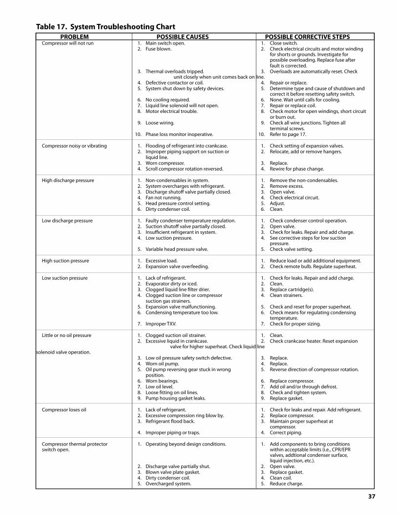
�7
Table17.SystemTroubleshootingChart PROBLEM POSSIBLECAUSES POSSIBLECORRECTIVESTEPS Compressor will not run 1. Main switch open. 1. Close switch. 2. Fuse blown. 2. Check electrical circuits and motor winding for shorts or grounds. Investigate for possible overloading. Replace fuse after fault is corrected. 3. Thermal overloads tripped. 3. Overloads are automatically reset. Check unit closely when unit comes back on line. 4. Defective contactor or coil. 4. Repair or replace. 5. System shut down by safety devices. 5. Determine type and cause of shutdown and correct it before resetting safety switch. 6. No cooling required. 6. None. Wait until calls for cooling. 7. Liquid line solenoid will not open. 7. Repair or replace coil. 8. Motor electrical trouble. 8. Check motor for open windings, short circuit or burn out. 9. Loose wiring. 9. Check all wire junctions. Tighten all terminal screws. 10. Phase loss monitor inoperative. 10. Refer to page 17.
Compressor noisy or vibrating 1. Flooding of refrigerant into crankcase. 1. Check setting of expansion valves. 2. Improper piping support on suction or 2. Relocate, add or remove hangers. liquid line. 3. Worn compressor. 3. Replace. 4. Scroll compressor rotation reversed. 4. Rewire for phase change.
High discharge pressure 1. Non-condensables in system. 1. Remove the non-condensables. 2. System overcharges with refrigerant. 2. Remove excess. 3. Discharge shutoff valve partially closed. 3. Open valve. 4. Fan not running. 4. Check electrical circuit. 5. Head pressure control setting. 5. Adjust. 6. Dirty condenser coil. 6. Clean.
Low discharge pressure 1. Faulty condenser temperature regulation. 1. Check condenser control operation. 2. Suction shutoff valve partially closed. 2. Open valve. 3. Insufficient refrigerant in system. 3. Check for leaks. Repair and add charge. 4. Low suction pressure. 4. See corrective steps for low suction pressure. 5. Variable head pressure valve. 5. Check valve setting.
High suction pressure 1. Excessive load. 1. Reduce load or add additional equipment. 2. Expansion valve overfeeding. 2. Check remote bulb. Regulate superheat.
Low suction pressure 1. Lack of refrigerant. 1. Check for leaks. Repair and add charge. 2. Evaporator dirty or iced. 2. Clean. 3. Clogged liquid line filter drier. 3. Replace cartridge(s). 4. Clogged suction line or compressor 4. Clean strainers. suction gas strainers. 5. Expansion valve malfunctioning. 5. Check and reset for proper superheat. 6. Condensing temperature too low. 6. Check means for regulating condensing temperature. 7. Improper TXV. 7. Check for proper sizing.
Little or no oil pressure 1. Clogged suction oil strainer. 1. Clean. 2. Excessive liquid in crankcase. 2. Check crankcase heater. Reset expansion valve for higher superheat. Check liquid line solenoid valve operation. 3. Low oil pressure safety switch defective. 3. Replace. 4. Worn oil pump. 4. Replace. 5. Oil pump reversing gear stuck in wrong 5. Reverse direction of compressor rotation. position. 6. Worn bearings. 6. Replace compressor. 7. Low oil level. 7. Add oil and/or through defrost. 8. Loose fitting on oil lines. 8. Check and tighten system. 9. Pump housing gasket leaks. 9. Replace gasket.
Compressor loses oil 1. Lack of refrigerant. 1. Check for leaks and repair. Add refrigerant. 2. Excessive compression ring blow by. 2. Replace compressor. 3. Refrigerant flood back. 3. Maintain proper superheat at compressor. 4. Improper piping or traps. 4. Correct piping.
Compressor thermal protector 1. Operating beyond design conditions. 1. Add components to bring conditions switch open. within acceptable limits (i.e., CPR/EPR valves, addtional condenser surface, liquid injection, etc.). 2. Discharge valve partially shut. 2. Open valve. 3. Blown valve plate gasket. 3. Replace gasket. 4. Dirty condenser coil. 4. Clean coil. 5. Overcharged system. 5. Reduce charge.
�8
PreventiveMaintenanceUnitCoolersAt every six month interval, or sooner if local conditions cause clogging or fouling of air passages through the finned surface, the following items should be checked.
1) Visually inspect unit • Look for signs of corrosion on fins, cabinet, copper tubing and solder joints.
• Look for excessive or unusual vibration for fan blades or sheet metal panels when in operation. Identify fan cell(s) causing vibration and check motor and blade carefully.
• Look for oil stains on headers, return bends, and coil fins. Check any suspect areas with an electronic leak detector.
• Check drain pan to insure that drain is clear of debris, obstructions or ice buildup and is free draining.
2) Clean evaporator coil and blades • Periodic cleaning can be accomplished by using a brush, pressurized water or a commercially available evaporator coil cleaner or mild detergent. Never use an acid based cleaner. Follow label directions for appropriate use. Be sure the product you use is approved for use in your particular application.
• Flush and rinse coil until no residue remains.
• Pay close attention to drain pan, drain line and trap.
3) Check the operation of all fans and ensure airflow is unobstructed • Check that each fan rotates freely and quietly. Replace any fan motor that does not rotate smoothly or makes an unusual noise.
• Check all fan set screws and tighten if needed.
• Check all fan blades for signs of stress or wear. Replace any blades that are worn, cracked or bent.
• Verify that all fan motors are securely fastened to the motor rail.
• Lubricate motors if applicable.
4) Inspect electrical wiring and components • Visually inspect all wiring for wear, kinks, bare areas and discoloration. Replace any wiring found to be damaged.
• Verify that all electrical and ground connections are secure, tighten if necessary.
• Check operation/calibration of all fan cycle and defrost controls when used.
• Look for abnormal accumulation of ice patterns and adjust defrost cycles accordingly
• Compare actual defrost heater amp draw against unit data plate.
• Visually inspect heaters to ensure even surface contact with the coil. If heaters have crept, decrease defrost termination temperature and be sure you have even coil frost patterns. Re-align heaters as needed.
• Check drain line heat tape for proper operation (supplied and installed by others).
5) Refrigeration Cycle • Check unit cooler superheat and compare reading for your specific application
• Visually inspect coil for even distribution
AirCooledCondensingUnits
Quarterly
1) Visually inspect unit • Look for signs of oil stains on interconnection piping and condenser coil. Pay close attention to areas around solder joints, building penetrations and pipe clamps. Check any suspect areas with an electronic leak detector. Repair any leaks found and add refrigerant as needed.
• Check condition of moisture indicator/sightglass in the sight glass if so equipped. Replace liquid line drier if there is indication of slight presence of moisture. Replace refrigerant, oil and drier if moisture concentration is indicated to be high.
• Check moisture indicator/sightglass for flash gas. If found check entire system for refrigerant leaks and add refrigerant as needed after repairing any leaks.
• Check compressor sightglass (if equipped) for proper oil level.
• Check condition of condenser. Look for accumulation of dirt and debris (clean as required).
• Check for unusual noise or vibration. Take corrective action as required.
• Inspect wiring for signs of wear or discoloration and repair if needed.
• Check and tighten all flare connections.
Semi-Annually
2) Repeat all quarterly inspection items.
3) Clean condenser coil and blades • Periodic cleaning can be accomplished by using a brush, pressurized water and a commercially available foam coil cleaner. If foam cleaner is used, it should not be an acid based cleaner. Follow label directions for appropriate use.
• Rinse until no residue remains.
4) Check operation of condenser fans • Check that each fan rotates freely and quietly. Replace any fan motor that does not rotate smoothly or makes excessive noise.
• Check all fan blade set screws and tighten as required.
• Check all fan blades for signs of cracks, wear or stress. Pay close attention to the hub and spider. Replace blades as required.
• Verify that all motors are mounted securely.
• Lubricate motors if applicable. Do not lubricate permanently sealed, ball bearing motors.
5) Inspect electrical wiring and components • Verify that all electrical and ground connections are secure, tighten as required.
�9
• Check condition of compressor and heater contactors. Look for discoloration and pitting. Replace as required.
• Check operation and calibration of all timers, relays pressure controls and safety controls.
• Clean electrical cabinet. Look for signs of moisture, dirt, debris, insects and wildlife. Take corrective action as required.
• Verify operation of crankcase heater by measuring amp draw.
6) Check refrigeration cycle • Check suction, discharge and net oil pressure readings. If abnormal take appropriate action.
• Check operation of demand cooling, liquid injection or unloaders if so equipped.
• Check pressure drop across all filters and driers. Replace as required.
• Verify that superheat at the compressor conforms to specification. (30°F to 45°F)
• Check pressure and safety control settings and verify proper operation.
Annually
7) In addition to quarterly and semiannual maintenance checks, submit an oil sample for analysis • Look for high concentrations of acid or moisture. Change oil and driers until test results read normal.
• Investigate source of high metal concentrations, which normally are due to abnormal bearing wear. Look for liquid refrigerant in the crankcase, low oil pressure or low superheat as a possible source.
8) Inspect suction accumulator (if equipped) • If the accumulator is insulated remove insulation and inspect for leaks and corrosion.
• Pay close attention to all copper to steel brazed connections
• Wire brush all corroded areas and peeling paint.
• Apply an anticorrosion primer and paint as required. Re-insulate if applicable.
AirCooledCondensersandFluidCoolers
At every six month interval, or sooner if local conditions cause clogging or fouling of air passages through the finned surface, the following items should be checked.
1) Visually inspect unit • Look for signs of corrosion on fins, cabinet, copper tubing and solder joints.
• Look for excessive or unusual vibration for fan blades or sheet metal panels when in operation. Identify fan cell(s) causing vibration and check motor and blade carefully.
• Look for oil stains on headers, return bends, and coil fins. Check any suspect areas with an electronic leak detector.
2) Clean condenser coil and blades• Periodic cleaning can be accomplished by using brush,
pressurized water or a commercially available coil cleaning foam. If a foam cleaner is used, it should not be an acid based cleaner. Follow label directions for appropriate use.
• Clear unnecessary trash and debris away from condenser.
3) Check the operation of all fans• Check that each fan rotates freely and quietly. Replace
any fan motor that does not rotate smoothly or makes an unusual noise.
• Check all fan set screws and tighten if needed.
• Check all fan blades for sighs of stress or wear. Replace any blades that are worn, cracked or bent.
• Verify that all fan motors are securely fastened to the motor rail.
• Lubricate motors if applicable (most Heatcraft condenser motors are permanently sealed ball bearing type and do not require lubrication)
4) Inspect electrical wiring and components• Visually inspect all wiring for wear, kinks, bare areas and
discoloration. Replace any wiring found to be damaged.
• Verify that all electrical and ground connections are secure, tighten if necessary.
• Check operation/calibration of all fan cycle controls when used.
Commercial Refrigeration Parts
ReplacementPartsby
InterLink is your link to a complete line of dependable and certified commercial refrigeration parts, accessories and innovative electronic controls for all Heatcraft Refrigeration Products (HRP) brands - including Bohn, Larkin, Climate Control and Chandler. At InterLink, we provide our wholesalers with a comprehensive selection of product solutions and innovative technologies for the installed customer base. And every product is built to ensure the same high performance standards with which all HRP brands are built — backed by a dedicated team to serve every customer need, delivering at the best lead times in the industry.
Replacement parts should be obtained from your local InterLink wholesaler. Replacement parts, which are covered under the terms of the warranty statement on page 2 of this manual, will be reimbursed for total part cost only. The original invoice from the parts supplier must accompany all warranty claims for replacement part reimbursement. Heatcraft Refrigeration Products reserves the right to adjust the compensation amount paid on any parts submitted for warranty reimbursement when a parts supplier's original invoice is not provided with a claim. Formoreinformation,call800-686-7278orvisitwww.interlinkparts.com.
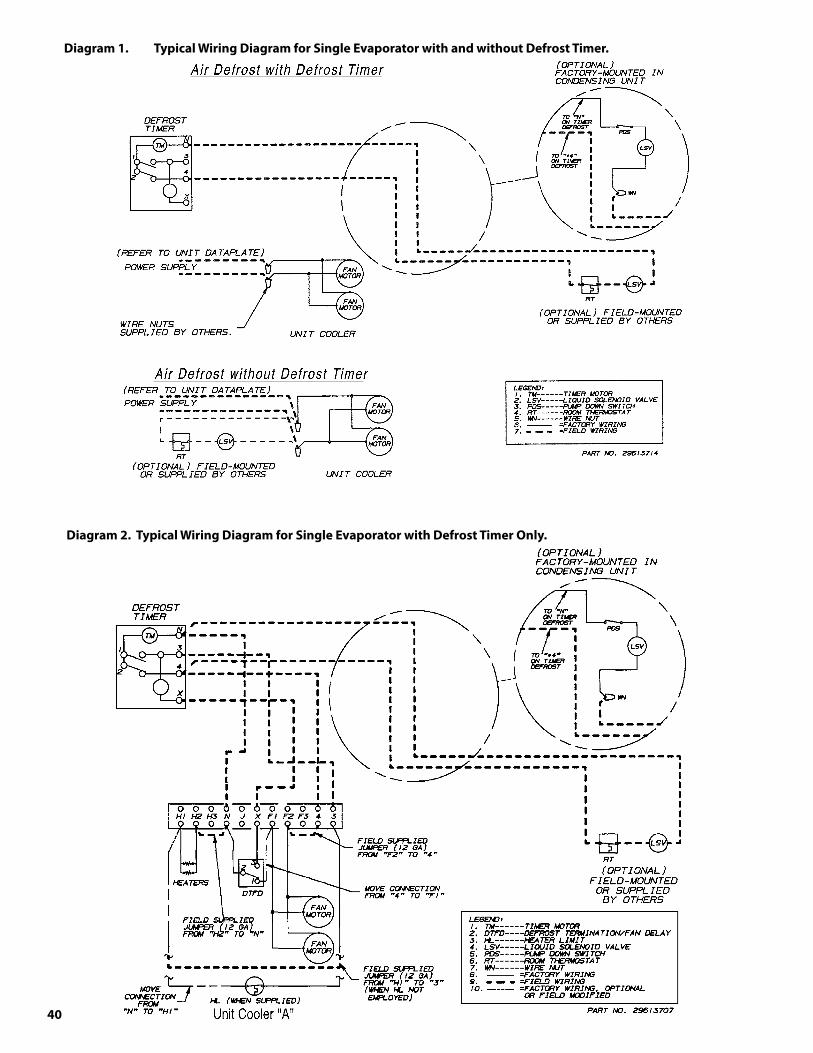
40
Diagram1. TypicalWiringDiagramforSingleEvaporatorwithandwithoutDefrostTimer.
Diagram2.TypicalWiringDiagramforSingleEvaporatorwithDefrostTimerOnly.
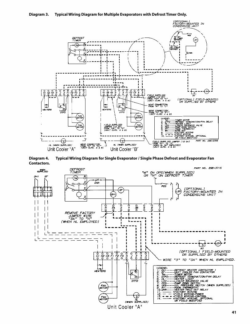
41
Diagram�. TypicalWiringDiagramforMultipleEvaporatorswithDefrostTimerOnly.
Diagram4. TypicalWiringDiagramforSingleEvaporator/SinglePhaseDefrostandEvaporatorFan Contactors.
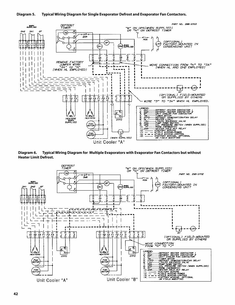
42
Diagram5. TypicalWiringDiagramforSingleEvaporatorDefrostandEvaporatorFanContactors.
Diagram6. TypicalWiringDiagramforMultipleEvaporatorswithEvaporatorFanContactorsbutwithout HeaterLimitDefrost.
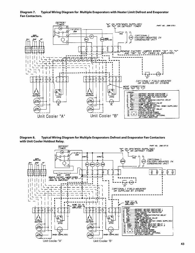
4�
Diagram8. TypicalWiringDiagramforMultipleEvaporatorsDefrostandEvaporatorFanContactors withUnitCoolerHoldoutRelay.
Diagram7. TypicalWiringDiagramforMultipleEvaporatorswithHeaterLimitDefrostandEvaporator FanContactors.

44
Diagram10. TypicalWiringDiagramforDefrostContactorwithEvaporatorHoldoutRelay withHeaterLimit.
Diagram9. TypicalWiringDiagramforDefrostContactorwithEvaporatorHoldoutRelay without HeaterLimit.
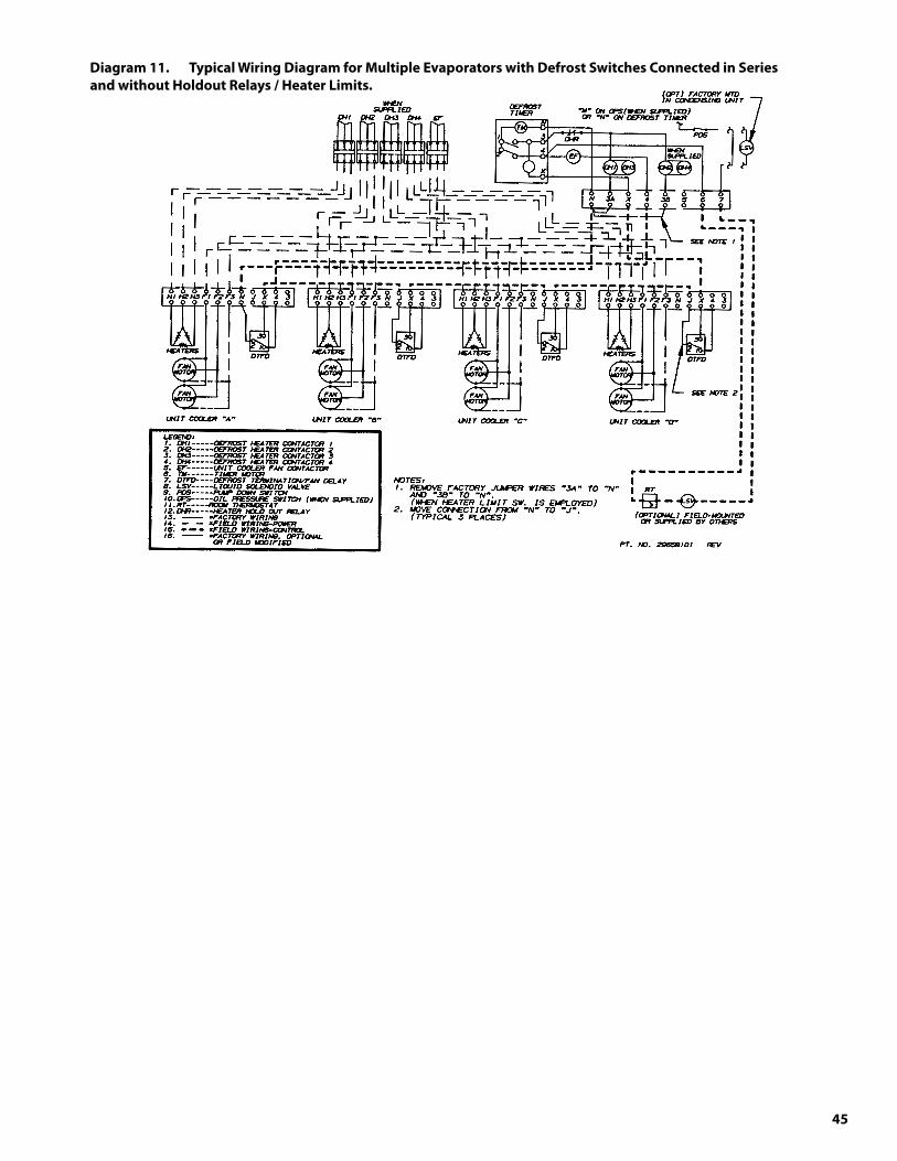
45
Diagram11. TypicalWiringDiagramforMultipleEvaporatorswithDefrostSwitchesConnectedinSeries andwithoutHoldoutRelays/HeaterLimits.

46
SystemReferenceData
The following information should be filled out and signed by Refrigeration Installation Contractor at time of start-up.
Date System Installed: _____________________________________________________
Installer and Address: _____________________________________________________
_____________________________________________________
_____________________________________________________
CondensingUnit Unit Model#: ________________________________________
Unit Serial #: ________________________________________
Compressor Model #: ____________________ Compressor Model #: _________________
Compressor Serial #: ____________________ Compressor Serial #: __________________
Electrical _________________ Volts __________________ Phase _______
Voltage at Compressor L1__________ L2 ___________ L3 ___________
Amperage at Compressor L1__________ L2 ___________ L3 ___________
Evaporator(s) Quantity ________________________________________
Evaporator Model #: ____________________ Evaporator Model #: __________________
Evaporator Serial #: ____________________ Evaporator Serial #: __________________
Electrical _________________ Volts __________________ Phase _______
Expansion Valve Manufacturer/Model ____________________ _______________________
Ambient at Start-Up _____________________________˚F
Design Box Temperature ______________________˚F _________________________˚F
Operating Box Temperature ______________________˚F __________________________˚F
Thermostat Setting ____________________________˚F __________________________˚F
Defrost Setting _____ / day ______ minutes fail-safe ______/day ______minutes fail-safe
Compressor Discharge Pressure _____________________PSIG ____________________PSIG
Compressor Suction Pressure _____________________PSIG ____________________PSIG
Suction Line Temperature @ Comp. ______________________˚F ______________________˚F
Discharge Line Temperature @ Comp. ____________________˚F ______________________˚F
Superheat at Compressor _____________________˚F ______________________˚F
Suction Line Temperature @ Evaporator ___________________˚F ______________________˚F
Superheat at Evaporator _____________________˚F ______________________˚F
Evacuation: # times _______ Final Micron_______ # Times ________ Final Micron_______
Evaporator Drain Line Trapped Outside of Box: yes no
ServiceRecord
A permanent data sheet should be prepared on each refrigeration system at an installation, with a copy for the owner and the original for the installing contractor's files.
If another firm is to handle service and maintenance, additional copies should be prepared as necessary.

47
Since product improvement is a continuing effort, we reserve the right to make changes in specifications without notice.
CLIMATE
CONTROL Commercial Refrigeration Parts
The name behind the brands you trust.™