HEAT TRANSFER OF ICE SLURRIES IN PIPES - … et al 99.pdfHEAT TRANSFER OF ICE SLURRIES IN PIPES ......
18
106 First Workshop on Ice Slurries of the International Institute of Refrigeration 27-28 May 1999 Yverdon-les-Bains, Switzerland HEAT TRANSFER OF ICE SLURRIES IN PIPES Peter W. Egolf Swiss Federal Laboratories for Materials Testing and Research CH-8600 Dübendorf, Switzerland Osmann Sari, Francois Meili, Philippe Moser, Didier Vuarnoz École d'Ingénieurs du Canton de Vaud CH-1401 Yverdon-les-Bains, Switzerland Some basic ideas of the heat transfer of ice slurries are discussed. The equations des- cribing a flow of a Bingham fluid through a tube with a heat flux over the boundary are presented. The theory shows that familiar relations known in the field of heat exchangers, e.g. the logarithmic-mean temperature difference, do not always apply. – With a device, designed to measure the heat transfer coefficients in tubes, first exper- imental data on the specific heat capacity have been obtained. They are compared with model results. The velocity profile of a laminar ice slurry flow has been mesured with an ultra-sound velocity profile sensor. Furthermore, ice particles of a water/etha- nol ice slurry have been observed under a microscope. 1. INTRODUCTION In classical refrigeration technology the working fluids usually show Newtonian be- aviour. Therefore, the molecular friction can be described by a single quantity, the dy- namic viscosity. The occurrence of fine-crystalline ice slurries - which are clearly Non- Newtonian fluids - request knowledge of basic rheology. In rheology scientists deal with complex mixtures (see for example Ref. [1]). A large number of these fluids can be described as pseudohomogenous multiphase mixtures. Ice slurries are multi-component and biphase fluids. The time-independent viscous fluids are classified as follows: 1) Newtonian fluids 2) Pseudoplastics 3) Dilatant fluids 4) Bingham fluids 5) Yield-pseudoplastics. Furthermore there are time-dependent fluids, the 1) Thixotropic fluids (the shear stress decreases with time) 2) Rheopectic fluids (the shear stress increases with time).
Transcript of HEAT TRANSFER OF ICE SLURRIES IN PIPES - … et al 99.pdfHEAT TRANSFER OF ICE SLURRIES IN PIPES ......
106 First Workshop on Ice Slurries of the International Institute of Refrigeration 27-28 May 1999 Yverdon-les-Bains, Switzerland
HEAT TRANSFER OF ICE SLURRIES IN PIPES
Peter W. Egolf Swiss Federal Laboratories for Materials Testing and Research
CH-8600 Dübendorf, Switzerland
Osmann Sari, Francois Meili, Philippe Moser, Didier Vuarnoz École d'Ingénieurs du Canton de Vaud
CH-1401 Yverdon-les-Bains, Switzerland Some basic ideas of the heat transfer of ice slurries are discussed. The equations des-cribing a flow of a Bingham fluid through a tube with a heat flux over the boundary are presented. The theory shows that familiar relations known in the field of heat exchangers, e.g. the logarithmic-mean temperature difference, do not always apply. – With a device, designed to measure the heat transfer coefficients in tubes, first exper-imental data on the specific heat capacity have been obtained. They are compared with model results. The velocity profile of a laminar ice slurry flow has been mesured with an ultra-sound velocity profile sensor. Furthermore, ice particles of a water/etha-nol ice slurry have been observed under a microscope. 1. INTRODUCTION In classical refrigeration technology the working fluids usually show Newtonian be-aviour. Therefore, the molecular friction can be described by a single quantity, the dy-namic viscosity. The occurrence of fine-crystalline ice slurries - which are clearly Non-Newtonian fluids - request knowledge of basic rheology. In rheology scientists deal with complex mixtures (see for example Ref. [1]). A large number of these fluids can be described as pseudohomogenous multiphase mixtures. Ice slurries are multi-component and biphase fluids. The time-independent viscous fluids are classified as follows: 1) Newtonian fluids 2) Pseudoplastics 3) Dilatant fluids 4) Bingham fluids 5) Yield-pseudoplastics. Furthermore there are time-dependent fluids, the 1) Thixotropic fluids (the shear stress decreases with time) 2) Rheopectic fluids (the shear stress increases with time).
First Workshop on Ice Slurries of the International Institute of Refrigeration 27-28 May 1999 Yverdon-les-Bains, Switzerland
107
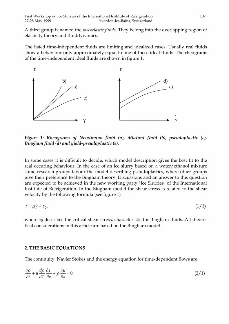
A third group is named the viscoelastic fluids. They belong into the overlapping region of elasticity theory and fluiddynamics. The listed time-independent fluids are limiting and idealized cases. Usually real fluids show a behaviour only approximately equal to one of these ideal fluids. The rheograms of the time-independent ideal fluids are shown in figure 1. b) d) a) e) c) Figure 1: Rheograms of Newtonian fluid (a), dilatant fluid (b), pseudoplastic (c), Bingham fluid (d) and yield-pseudoplastic (e). In some cases it is difficult to decide, which model description gives the best fit to the real occuring behaviour. In the case of an ice slurry based on a water/ethanol mixture some research groups favour the model describing pseudoplastics, where other groups give their preference to the Bingham theory. Discussions and an answer to this question are expected to be achieved in the new working party "Ice Slurries" of the International Institute of Refrigeration. In the Bingham model the shear stress is related to the shear velocity by the following formula (see figure 1)
0 , (1/1)
where 0 describes the critical shear stress, characteristic for Bingham fluids. All theore-
tical considerations in this article are based on the Bingham model. 2. THE BASIC EQUATIONS The continuity, Navier Stokes and the energy equation for time-dependent flows are
0
x
u
x
T
dT
du
t
(2/1)
.
.

108 First Workshop on Ice Slurries of the International Institute of Refrigeration 27-28 May 1999 Yverdon-les-Bains, Switzerland
01 0
2
2
0
r
T
dT
d
r
u
r
T
r
u
dT
d
rr
u
rx
p
x
uu
t
u
(2/2)
02
2
r
Tk
r
T
r
T
T
dk
r
T
r
k
x
pu
x
Tuc
t
Tc pp , (2/3)
where all the physical properties are functions of the temperature. In Ref. [2] the are de-rived from basic physical principals taking several approximative assumptions into con-sideration. 3. THE CONTINUOUS-PROPERTIES MODEL The kinematic boundary condition is assumed to be the no-slip boundary condition and the thermal condition may, for example, describe a constant heat flux density q in x-
direction
Rrqkr
Tu
,
1,0 . (3/1a-c)
Special case: no flow. Then
0u . (3/2) Equation (2/1) vanishes and from (2/3) it follows
r
T
r
TT
r
T
rr
TT
t
T)(
1)(
2
2
, (3/3)
which is the continuous-properties model in cylindrical co-ordinates. The nonlinear coef-
ficients and are defined in Ref. [3]. From (2/2) it follows that a further condition re-mains
01 0
0
r
T
dT
d
rx
p , (3/4)
which is a relation between the pressure drop per unit length in downstream direction and the radial directional derivative of the critical shear stress.

First Workshop on Ice Slurries of the International Institute of Refrigeration 27-28 May 1999 Yverdon-les-Bains, Switzerland
109
4. HEAT TRANSFER MODEL 4.1 General theory For a steady state from equation (2.3) and the definition of enthalpy dh=cpdT it follows
that
dpdhudpudh
1
(4.1/1a,b)
is fulfilled, the following formula applies to an infinitesimal small control volume spanned over the entire cross section of the pipe
SPrPr AqAxuhAxxuh )()( . (4.1/2)
Figure 2: Control volume for the derivation of equations describing the heat transfer to a flowing ice slurry.
The following average over the domain P - with area PA - has been introduced
hudArxtA
xt
P
PP
r ,,,),,(1
),(
. (4.1/3)
In cylindrical co-ordinates the differential area and total area of the cross section are
2
0 0
,2 RArdrdrrddA P
R R
P , (4.1/4a-c)
u
R
q.
P
S
x
x x+
r

110 First Workshop on Ice Slurries of the International Institute of Refrigeration 27-28 May 1999 Yverdon-les-Bains, Switzerland
and the space-averaged quantity in the radial direction is
R
r rdrrxtR
xt0
2),,(
2),( . (4.1/5)
Furthermore we have
xRAS 2 . (4.1/6)
From equations (4.1/2), (4.1/4c) and (4.1/6) a new equation is derived
R
xq
A
Aqxuhxxuh
P
Srr
2)()( . (4.1/7a,b)
Now, we introduce the definition of a mean weighted enthalpy density
rrr
r uhuhu
uhh
: . (4.1/8a,b)
The inequality of Schwarz states that for positive functions f and g
rrr gffg . (4.1/9)
Now a correlation coefficient is defined
10 ,,
gf
rr
rgf R
gf
fgR , (4.1/10a,b)
which is a direct result of equation (4.1/9). Special case (CP1):
1, hurrr Rhuuh . (4.1/11a,b)
Assuming the enthalpy density to be positive (not as in Ref. [3]) and from the definition (4.1/8a) we can conclude that
rhh . (4.1/12)
Furthermore it is clear that

First Workshop on Ice Slurries of the International Institute of Refrigeration 27-28 May 1999 Yverdon-les-Bains, Switzerland
111
PrPr
A
muAum
(4.1/13a,b)
describes the mass flow, which is not a function of the downstream co-ordinate x. This argumentation is correct because of mass conservation. Inserting (4.1/8b) into (4.1/7a) we derive
,)(
)()()()()(
P
S
P
Prr
A
Aq
A
mxh
A
mxxhxuxhxxuxxh
(4.1/14a,b)
a formula, which is obtained by also applying formula (4.1/13b). Therefore one concludes that
xm
qRA
m
qxhxxh S
2)()( , (4.1/15a,b)
respectively
m
qR
x
xhxxh
2
)()(
. (4.1/16)
In the limit x equal to zero we have
m
qR
dx
hd
x
xhxxh
x
2
)()(lim
0
. (4.1/17a,b)
4.2 Constant heat flux density Now we are prepared to study the case, when a constant heat flux density is applied. Then from equation (4.1/17a,b), by an integration one obtains
Lxhxm
qRxh 0),0(2)(
. (4.2/1)
This linear relationship is fulfilled in any case. Introducing a correlation function in ana-logy to the correlation coefficient (4.1/10a) leads to
112 First Workshop on Ice Slurries of the International Institute of Refrigeration 27-28 May 1999 Yverdon-les-Bains, Switzerland
)()()()(
)( ,,
xhxRu
xhuxRxh rhu
r
rrhu
. (4.2/2a,b)
Therefore one concludes that
)0(2
)(
1)(
)(
1)(
,,
hxm
qR
xRxh
xRxh
huhur
. (4.2/3a,b)
The space-averaged enthalpy density across the pipe section is not necessarily linear. Special case (CP1): Then
)0(2)(,0,1)(, rrhu hx
m
qRxhLxxR
. (4.2/4a,b)
The linearity in x is also fulfilled for the non-weighted enthalpy density <h>r. It will be a great challenge to obtain good experimental and numerical data to check if
1, huR . If this is not the case the problem becomes very difficult to solve, and (probab-
ly) no analytical solutions will be available. Then only numerical simulations can produ-ce quantitative useful results.
Now Newton's law on heat transfer is applied. At this stage the surface temperature TS is not yet assumed to be constant
)()()( xTxTxq rS . (4.2/5)
Substitution into equation (4.1/17b) leads to
)()()(2 xTxTxm
R
dx
hdrS
. (4.2/6)
To obtain a differential equation that can be solved here h must be expressed by the temperature. As it already has been stressed, this leads to a very complicated relation. Therefore, only the special case (CP1) is investigated. Special case (CP1): Considering equation (4.2/6) and with the help of equation (4.1/12) one obtains
First Workshop on Ice Slurries of the International Institute of Refrigeration 27-28 May 1999 Yverdon-les-Bains, Switzerland
113
)()()(2 xTxTxm
Rh
dx
drSr
. (4.2/7)
Because of
hudx
d
dx
drr ,, (4.2/8)
from equation (4.2/7) it follows that
)()()(2 xTxTxm
R
dx
dTc rSrp
. (4.2/9)
By applying (4.1/10a) we obtain
rrp
x
Tc
rpdx
dTcR
dx
dTc
p
,
. (4.2/10)
Special case (CP2):
LxR
x
Tcp
,0,1,
. (4.2/11)
Then from (4.2/9)
)()()(
)(2 xTxT
xc
x
m
R
dx
dTrS
rpr
. (4.2/12)
4.3 Constant surface temperature If the surface temperature is constant
0dx
dTconstT S
S . (4.3/1a,b)
Therefore the derivative (4.3/1b) can be subtracted from the left side of equation (4.2/12). By applying (4.2/8) it follows that
)()(
)(2)( xT
xc
x
m
RxT
dx
dr
rpr
, (4.3/2)
114 First Workshop on Ice Slurries of the International Institute of Refrigeration 27-28 May 1999 Yverdon-les-Bains, Switzerland
where the following definition has been introduced
)()( xTTxT rSr . (4.3/3)
Equation (4.3/2) is identical to
)(
)(2)(log
xc
x
m
RxT
dx
d
rpr
. (4.3/4)
By an integration one obtains
1)(
)(2)(log cdx
xc
x
m
RxT
rpr
. (4.3/5)
The boundary condition at the inlet of the heat exchanging pipe (x=0) is
)0(log1 rTc . (4.3/6)
This is inserted into (4.3/5)
x
rpr
r dyyc
y
m
R
T
xT
0 )(
)(2
)0(
)(log
. (4.3/7)
At the outlet of the heat exchanger (x=L) one obtains
L
rpr
r dyyc
y
m
R
T
LT
0 )(
)(2
)0(
)(log
, (4.3/8)
respectively
L
rpr
r dyyc
y
m
R
T
LT
0 )(
)(2exp
)0(
)(
. (4.3/9)
Special case (CP3):
Lxtconscxc prp ,0,tan)( . (4.3/10)
For an ice slurry this applies when
Lxxcccm
Aqrp
xp
p
S ,0,)(min,1 minmin
. (4.3/11)

First Workshop on Ice Slurries of the International Institute of Refrigeration 27-28 May 1999 Yverdon-les-Bains, Switzerland
115
When a large heat capacity per unit time is transported by convection through the tube and the heat impact over the wall is small, then the temperature of the ice slurry alters only slightly, and then the heat capacity is approximately constant. Now equation (4.3/9) can be simplified
p
x
r
r
cm
RL
T
LT
2exp
)0(
)(. (4.3/12)
In this equation the global heat transfer coefficient is introduced
L
x dxxL 0
)(1
: . (4.3/13)
Assuming special case (CP1) the totally transferred heat is
)0()()0()( rrrr hLhmuhLuhQ . (4.3/14a,b)
Because of the constant specific heat cP one obtains
)0()( rrp TLTcmQ . (4.3/15)
By adding and subtracting the surface temperature TS this equation evolves to
)()0( LTTTTcmQ rSrSp . (4.3/16)
Substituting (4.3/3)
)()0( LTTcmQ rrp . (4.3/17)
From (4.3/8), (4.3/10) and (4.3/13) one concludes that
p
x
r
r
cm
RL
T
LT
2
)0(
)(log . (4.3/18)
Solving for the heat capacity per time unit one obtains
)0(
)(log
2
r
r
xp
T
LT
RLcm
. (4.3/19)

116 First Workshop on Ice Slurries of the International Institute of Refrigeration 27-28 May 1999 Yverdon-les-Bains, Switzerland
This is inserted into equation (4.3/17). Then we obtain
)0(
)(log
)0()(:,2 log,log,
r
r
rrrrx
T
LT
TLTTTRLQ
, (4.3/20a,b)
which is the logarithmic-mean temperature difference (e.g. see Ref. [4]and [5]). 5. EXPERIMENTAL SET-UP The objective of the project group FIFE at the EIVD in Yverdon mainly consists of the determination of the heat transfer coefficients of fine-crystalline ice slurries in axisym-metric heat exchangers for various operating conditions. The device is shown in figure 3.
Figure 3: The experimental device at the thermodynamics laboratory of the EIVD. From the left to the right there is a refrigerating machine (with an ice generator), a storage tank and an apparatus with a horizontal insulated heat exchanger pipe mounted on the top. This pipe can be inclined in steps of 15°. Video and photographic pictures of flows are performed through a microscope. On each picture an ensemble of circa twenty ice particles can be observed.

First Workshop on Ice Slurries of the International Institute of Refrigeration 27-28 May 1999 Yverdon-les-Bains, Switzerland
117
The test facility “Coulis de glace”, with a refrigerating power of 9 kW, was designed and built at the thermal laboratory of engineering (LGT). A cylindrical aluminium heat exchanger with electric heating elements was designed, calculated and built together (see figure 4). This is our main part for the investigations of heat transfer phenomena in pipes.
Figure 4: The test facility to measure heat transfer coefficients and temperature profiles in tubes. The heat exchanger is composed of tree distinct elements and has a total length of three meters. The aluminium tube, where the heat transfer occurs, has a total length of one meter. The interior diameter is 23 mm and the outside diameter 60 mm. The cylinder is surrounded by electric heating elements with a maximum total heating power of 9 kW. An input and output insulating piece, each composed of tree elements of teflon, have an interior diameter of 23 mm and a length of 333 mm. They are added to obtain steady flow conditions at the inlet and outlet of the heat exchanger. The electric heating of the pipe leads to a constant heat flux density in the downstream
direction. Another research group – see Christensen and Kauffeld (Ref. 7) - has real-ised a constant surface temperature boundary condition in their experimental apparatus This is achieved by an evaporation of a refrigerant on the outer surface, e.g. of a pipe. The fluid temperatures and the temperatures at the interior surface in each of five sections of the heat exchanger are measured and determined.

118 First Workshop on Ice Slurries of the International Institute of Refrigeration 27-28 May 1999 Yverdon-les-Bains, Switzerland
In the apparatus all the temperature measurements are carried out with Pt 100 sensors. For
preliminary tests, as described in Ref. 6, water was used as a working fluid. The specific heat is determined by measuring the power of the electric heating, the mass flow at the inlet and the fluid temperatures in the inlet and outlet of the heat exchanger. Four temperature sensors are placed at equidistant positions over one section to evaluate a space-averaged value. The measurements are confirmed by sensors with higher inertia and with a sensor length equivalent to the section diameter. The relative fluctuations of the temperature signals are approximately 0.17 % (taking the average temperature as a basis for the calculation). 6. MEASUREMENTS 6.1 Specific heat
The specific heat is determined and compared with results of the physical properties
model (see Ref. 3). The agreement of the compared experimental and numerical data is good (see figure 5). The numerically calculated specific heat reaches a maximum value of 53.200 kJ/kg and the measured value is 46.700 kJ/kg K. The temperature at which the specific heat increases corresponds to the expected freezing starting point of water/ethanol-ice solidification. Above the freezing region the calculated specific heat is constant, with a value of 4.353 kJ/kg K, and in comparison a mean value of 4,156 kJ/kg K is measured. On the left of the maximum the measured specific heat also decreases in agreement with numerical results. During a cooling process with approximately constant cooling power in the single-phase liquid mixture the temperature decreases rapidly, because only sensible heat must be re-leased. When the freezing domain is reached also latent heat must be removed, therefore, the temperature decreases more slowly. This leads to a kink, when the ice creation sets in. This kink is taken to determine the freezing point. With 11 mass- % ethanol content the ice particles are formed at –4.48°C (see figure 6). Numerical calculation results show an onset of freezing at a temperature of –4.45°C. The discontinuity in the calculated specific heat occurs at this temperature (see figure 5). All measurements are obtained under steady state conditions. The heat flux and flow rate have no influence on the specific heat, as it is confirmed by the different measurement ser-
ies in figure 5. For the serie No. 1 the heat flux is 78200 W/m2 and the flow rate 0.70
kg/s,
Specific heat (kJ/kg K)

First Workshop on Ice Slurries of the International Institute of Refrigeration 27-28 May 1999 Yverdon-les-Bains, Switzerland
119
Figure 5: The specific heat of an ice slurry produced with a 11 mass-% water/ethanol mix-ture. The figure shows a comparison between experimental data and theoretical results. Figure 6: Temperature measurement during the cooling process. Water solidification is characterized by a change of the slop of the temperature in function of time. This pheno-mena permits to determine the temperature when freezing occurs very exactly.
-5
-4.5
-4
-3.5
-3
-2.5
-2
0 1 2 3 4 5
Tem
per
atu
re (
°C)
Time (hour)
q=76.5 kW/m
m=0.70 kg/s
11 % ethanol
..
0
10
20
30
40
50
60
-15 -10 -5 0 5 10 15
q = 78.2 kW/m
m = 0.70 kg/s
q = 68.5 kW/m
m = 0.69 kg/s
q = 8.8 kW/m
m = 0.37 kg/s
Numerical
calculation
Sp
ecif
ic h
eat
(kJ/
kg
K)
Temperature (°C)
.
..
.
..
2
2
2
Temperature (°C)

120 First Workshop on Ice Slurries of the International Institute of Refrigeration 27-28 May 1999 Yverdon-les-Bains, Switzerland
for the serie No. 2 the heat flux is 68500 W/m2 and the flow rate 0,69 kg/s. For the serie
No. 3 the experimental quantities are 8800 W/m2 and 0,37 kg/s. The specific heat is di-
rectly related to the slope of the enthalpy (see Ref. 3). At the freezing point the discon-tinuous increase of the specific heat corresponds to a kink in the enthalpy curve. 6.2 Velocity profile
The Hagen-Poiseuille flow of Newtonian fluids is characterized by a parabolic velocity profile. Bingham fluids show a plug in the velocity profile, which is located symmetrically Figure 7: Velocity profile of ice slurry composed with 11 mass-% water/ethanol in a cylindrical tube. to the axis (see figure 7). This velocity profile was obtained with an ultrasonic velocity profile meter (UVP) applied to a flow in a plexiglas tube. A laminar flow of 0.35 kg/s with a temperature of –4.6 °C constitutes the experimental condition for this acquisition. The ex-perimental result has been obtained by taking an average of 1028 successive profiles. In Ref. [8] the formulas of a laminar Bingham flow are presented. It can be seen that an ex-perimental determination of r1 together with the pressure derivative in the downstream di-rection allows the calculation of the dynamic viscosity and critical shear stress. In a diplo-ma work, performed by Didier Vuarnoz, this method is used to determine viscous be-haviour of an ice slurry as a function of temperature. 6.3 Ice particles visualization
A microscopic visualization of the ice slurry permits to study the geometry of the ice particles (see figure 8). Physical properties as viscosity and critical shear stress and the heat transfer coefficients depend on the ice concentration and maybe also on the size of
-10
-5
0
5
10
0 200 400 600 800 1000
Rad
ial
coord
inat
e r
(mm
)
Velocity u (mm/s)
Plug
r
r
2
1
Radial coordinate r (mm)

First Workshop on Ice Slurries of the International Institute of Refrigeration 27-28 May 1999 Yverdon-les-Bains, Switzerland
121
the ice particles. The presented visualization of an ice slurry has been performed at -4.7
°C. The photograph shows particles with diameters of the order of 100 m. Statistics on these ice particles will be presented at the next IIR workshop on ice slurries in Paris.
Figure 8: Ice particles in a ice slurry suspension with a temperature of -4.7 °C and 11 mass-% water/ethanol. 7. CONCLUSIONS AND OUTLOOK A theoretical analysis of the heat transfer problem in a pipe is presented. It shows that one has to be very careful applying well-known relations of the theory of heat ex-changers. When a constant heat flux density occurs across the tube wall, a weighted ent-halpy density is a linear function of the downstream distance. In general the temperature averaged over the pipe section will not show such linear behaviour downstream. When the surface temperature is constant three conditions (critical points CP1, CP2 and CP3, which have been outlined in this article) must apply. Only then the logarithmic-mean temperature difference is valid. It is certain that in some practical applications this con-cept is meaningless. The experimental set-up to measure heat transfer coefficients and temperature profiles in tubes is very briefly discussed. More informations are found in an internal research report of the FIFE group (see Ref. [6]). First measurements of the specific heat capacity as a function of temperature, performed with the new device "COULIS DE GLACE", are compared with model results. In Ref. [3]
Temperature: -4.7 °C 11mass-% water/ethanol
scale:

122 First Workshop on Ice Slurries of the International Institute of Refrigeration 27-28 May 1999 Yverdon-les-Bains, Switzerland
the theoretical model is described in detail. The agreement between experimental data and numerical results is good. First measurements on velocity profiles with an ultra sound velocity profile meter are very encouraging. An average of an ensemble of 1028 velocity profiles clearly shows a rectangular central part symmetric to the axis and a parabolic decay toward the wall as predicted by the Bingham theory. Microscopic photographs of ice particles in a water/ethanol ice slurry have been performed. They also show spheroidal shapes similar to those observed by Kauffeld et al. (see Ref. [9]). Their ice particles have been created in a 3 % Mg Cl2 suspension. NOMENCLATURE Standard A area cp specific heat f positive function g positive function h enthalpy density k thermal conductivity m mass flow p pressure q heat flux density
r radial co-ordinate R correlation coefficient R radius of pipe t time T temperature u velocity x space co-ordinate downstream Greek
heat transfer coefficient
nonlinear coefficient
nonlinear coefficient
general variable
increment
angle in azimutal direction shear velocity
First Workshop on Ice Slurries of the International Institute of Refrigeration 27-28 May 1999 Yverdon-les-Bains, Switzerland
123
dynamic viscosity
density
shear stress
critical shear stress Indices min minimal P cross section of pipe S surface of pipe REFERENCES [1] G. W. Govier, K. Aziz, The Flow of Mixtures in Pipes. Van Nostrand Reinhold Publi-
shing Company, New York, 1972. [2] P. W. Egolf, O. Sari, F. Meili, Ph. Moser. Thermodynamics of Moving and Melting Ice
Slurries in Pipes. EUREKA FIFE report No. 5 (in preparation). [3] P. W. Egolf, B. Frei, The Continuous-Properties Model for Melting and Freezing applied
to Fine-Crystalline Ice Slurries. Proceedings of the First IIR workshop on Ice Slur-ries, 25-40, Yverdon-les-Bains, 28/29. May 1999.
[4] A. Bejan, Heat Transfer. John Wiley & Sons, New York, 1993. [5] F. Incropera, D. P. DeWitt, Fundamentals of Heat and Mass Transfer. John Wiley &
Sons, New York, Fourth edition, 1996. [6] O. Sari, Ph. Moser, G. Dunkel, F. Meili, Stand d'Essai Thermodynamique à l'École
d'Ingénieurs du Canton de Vaud. EUREKA FIFE report No. 1, February, 1999. [7] K. G. Christensen, M. Kauffeld, Heat Transfer Measurements with Ice Slurry. Pro-
ceedings of an IIR/IIF Int. Conf. on Heat Transfer Issues in Natural Refrigerants. Commission B1. University of Maryland, Washington D.C., November, 1997.
[8] P. W. Egolf, J. Brühlmeier, F. Özvegyi, F. Abächerli, P. Renold, Kältespeicherungsei-genschaften von Flo-Ice®. Forschungsbericht zuhanden der Stiftung zur Förderung des Zentralschweizerischen Technikums Luzern, 1996.
[9] Michael Kauffeld, Kim G. Christensen, Soren Lund, Torben M. Hansen, Proceed-ings of the First IIR workshop on Ice Slurries, 42-73, Yverdon-les-Bains, 27/28. May 1999.