Heat pump systems Water Chillers Dehumidifiers - HIDROS · How the heat pump works The source, the...
9
> > > Heat pump systems Dehumidifiers Water Chillers
Transcript of Heat pump systems Water Chillers Dehumidifiers - HIDROS · How the heat pump works The source, the...

>>>
Heat pump systems
Dehumidifiers
Water Chillers
2 www.hidros.it32 www.hidros.it3
How the heat pump works
The source, the user
Company Profile
What is a heat pump?
HIDROS was formed in 1993 as a distribution company operating in the humidification and dehumidification sector of the air conditioning market. The expansion was rapid and, as the knowledge of the market sector increased, opportunities for the development of specialist products were identified. The decision was therefore taken in 2001 to invest in a production facility and to manufacture their own design products. Since then, the company has added chillers, heat pumps and air handling units to its product portfolio.Today, HIDROS with its qualified staff, designs, develops and tests heat pumps, water chillers,
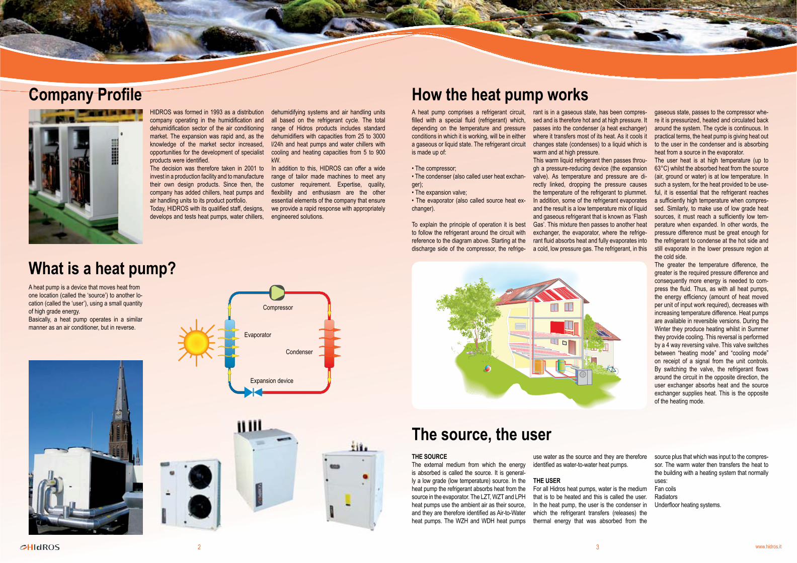
A heat pump comprises a refrigerant circuit, filled with a special fluid (refrigerant) which, depending on the temperature and pressure conditions in which it is working, will be in either a gaseous or liquid state. The refrigerant circuit is made up of:
• The compressor; • The condenser (also called user heat exchan-ger); • The expansion valve; • The evaporator (also called source heat ex-changer).
To explain the principle of operation it is best to follow the refrigerant around the circuit with reference to the diagram above. Starting at the discharge side of the compressor, the refrige-
dehumidifying systems and air handling units all based on the refrigerant cycle. The total range of Hidros products includes standard dehumidifiers with capacities from 25 to 3000 l/24h and heat pumps and water chillers with cooling and heating capacities from 5 to 900 kW. In addition to this, HIDROS can offer a wide range of tailor made machines to meet any customer requirement. Expertise, quality, flexibility and enthusiasm are the other essential elements of the company that ensure we provide a rapid response with appropriately engineered solutions.
rant is in a gaseous state, has been compres-sed and is therefore hot and at high pressure. It passes into the condenser (a heat exchanger) where it transfers most of its heat. As it cools it changes state (condenses) to a liquid which is warm and at high pressure. This warm liquid refrigerant then passes throu-gh a pressure-reducing device (the expansion valve). As temperature and pressure are di-rectly linked, dropping the pressure causes the temperature of the refrigerant to plummet. In addition, some of the refrigerant evaporates and the result is a low temperature mix of liquid and gaseous refrigerant that is known as ‘Flash Gas’. This mixture then passes to another heat exchanger, the evaporator, where the refrige-rant fluid absorbs heat and fully evaporates into a cold, low pressure gas. The refrigerant, in this
gaseous state, passes to the compressor whe-re it is pressurized, heated and circulated back around the system. The cycle is continuous. In practical terms, the heat pump is giving heat out to the user in the condenser and is absorbing heat from a source in the evaporator. The user heat is at high temperature (up to 63°C) whilst the absorbed heat from the source (air, ground or water) is at low temperature. In such a system, for the heat provided to be use-ful, it is essential that the refrigerant reaches a sufficiently high temperature when compres-sed. Similarly, to make use of low grade heat sources, it must reach a sufficiently low tem-perature when expanded. In other words, the pressure difference must be great enough for the refrigerant to condense at the hot side and still evaporate in the lower pressure region at the cold side. The greater the temperature difference, the greater is the required pressure difference and consequently more energy is needed to com-press the fluid. Thus, as with all heat pumps, the energy efficiency (amount of heat moved per unit of input work required), decreases with increasing temperature difference. Heat pumps are available in reversible versions. During the Winter they produce heating whilst in Summer they provide cooling. This reversal is performed by a 4 way reversing valve. This valve switches between “heating mode” and “cooling mode” on receipt of a signal from the unit controls. By switching the valve, the refrigerant flows around the circuit in the opposite direction, the user exchanger absorbs heat and the source exchanger supplies heat. This is the opposite of the heating mode.
A heat pump is a device that moves heat fromone location (called the ‘source’) to another lo-cation (called the ‘user’), using a small quantity of high grade energy. Basically, a heat pump operates in a similar manner as an air conditioner, but in reverse.
THE SOURCEThe external medium from which the energy is absorbed is called the source. It is general-ly a low grade (low temperature) source. In the heat pump the refrigerant absorbs heat from the source in the evaporator. The LZT, WZT and LPH heat pumps use the ambient air as their source, and they are therefore identified as Air-to-Water heat pumps. The WZH and WDH heat pumps
use water as the source and they are therefore identified as water-to-water heat pumps.
THE USERFor all Hidros heat pumps, water is the medium that is to be heated and this is called the user. In the heat pump, the user is the condenser in which the refrigerant transfers (releases) the thermal energy that was absorbed from the
Compressor
Condenser
Evaporator
Expansion device
source plus that which was input to the compres-sor. The warm water then transfers the heat to the building with a heating system that normally uses:Fan coilsRadiatorsUnderfloor heating systems.
4 www.hidros.it54 www.hidros.it5
77,8 %
10,5 %
6,6 %
3,7 %
1,4 %
1 kWh
4 kWh
Types of heat pumpsAIR TO WATER HEAT PUMPS; Air is used as the source. It has the advantage of being available at all times but with the disadvan-tage that, when the ambient temperature is close to or below 0°C, removal of heat will cause the heat exchanger to freeze and it is therefore necessary to incorporate a defrost system to clear the ice thus formed. Such a defrost system involves operating the 4 way valve to cause the refrigerant to pass in the opposite direction. This sends hot gas into the source exchanger and this melts the ice. Once the ice is clear, the heat pump reverses the valve again, returning to heating mode. The defrost cycle absorbs energy from the heat pump, energy that is not put into the hot water circuit thereby temporarily reducing the output. It can be estimated that, in major European countries, the energy absorbed by the defrost cycle is between 5 and 13% of the total heating output.
WATER TO WATER HEAT PUMPS; Water is used as the source. Using water tends to provide good performance and is not subject to variations caused by external climatic conditions (typical of air to water heat pumps). However, water is not always available, groundwater requires an extraction license and additional costs are incurred in the assembly of an external hydraulic circuit.
GROUND SOURCE HEAT PUMPS; In this case the source is the energy that is stored in the ground. Energy is absorbed from the ground by pipes through which brine (water/ glycol mixture), is circulating. The pipes can be in-stalled either vertically or horizontally, depending upon which approach absorbs the max amount energy.Horizontal pipes are normally buried at 1 or 1.5 metres depth to avoid variations in tem-perature caused by changing ambient conditions whilst maintaining the advantage of the effect of solar radiation. As a guide, it is normal to have underground piping equal to 2-3 times the area of the building to be heated. For vertical pipes, they are normally designed to go down to 100 meters deep in order to obtain, as an average, 5 kW per pipe. Ground source heat pumps have the ad-vantage of a constant C.O.P. and heating capacity as they are unaffected by changes in external climatic conditions, however, there is a substantial cost penalty related to the construction of the source exchanger.
HYBRID HEAT PUMPS; These units are primarily air to water heat pumps but also incorporate a small water source ex-changer. This provides the best of both worlds, taking advantage of the lower cost and ease of installation of air to water heat pumps whilst also obtaining (when required) the higher efficiencies that are typical of water to water heat pumps. When the ambient is high, the unit operates as an air to water heat pump. However, as the temperature of the air drops, the water source (can also be connected to a ground loop) is brought into play alongside the air source exchanger and the output and COP of the unit are maintained. By making use of both sources, it is possible to obtain an excellent ratio between cost and performance with average improvement in COP over the ambient range 0 to -10°C of 12%.
Efficiency of the heat pumpDuring its operation the heat pump:
• “Absorbs” electricity in the compressor;• “Absorbs” thermal energy from the source (air or water);• Releases thermal energy in the user heat exchanger (water).
The main advantage of the heat pump is the capacity to supply more Energy (thermal) than that required for its operation (electrical). The efficiency of a heat pump is measured by the coefficient of performance “C.O.P.” that is the RATIO between the thermal energy supplied to the user and the electric input power absorbed by the unit. The C.O.P. is variable depending on the type of the heat pump and the working
conditions but is generally in the region of 3 to 5. This means that for 1 kWh of electrical input energy, the unit will supply between 3 and 5 kWh of thermal energy to the user. The C.O.P. will vary and is dependant upon the tempe-rature at which the heat is transferred (user), the temperature of the source and, in the case of air source units, the amount of defrost re-quired.
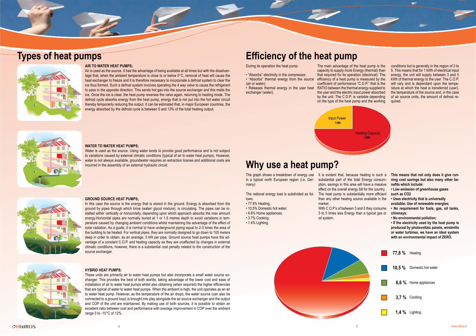
Why use a heat pump?The graph shows a breakdown of energy use in a typical north European region (i.e. Ger-many):
The national energy load is subdivided as fol-lows:• 77.8% Heating;• 10.5% Domestic hot water;• 6.6% Home appliances;• 3.7% Cooking;• 1.4% Lighting.
It is evident that, because heating is such a substantial part of the total Energy consum-ption, savings in this area will have a massive effect on the overall energy bill for the country.The heat pump is substantially more efficient than any other heating source available in the market. With C.O.P’s of between 3 and 5 they consume 3 to 5 times less Energy than a typical gas or oil system.
This means that not only does it give run-ning cost savings but also many other be-nefits which include:• Low emission of greenhouse gasessuch as CO2 • Uses electricity that is universallyavailable; Use of renewable energies;• No requirement for fuels, gas, oil tanks, chimneys;• No environmental pollution;• If the electricity used by the heat pump is produced by photovoltaic panels, windmills or water turbines, we have an ideal system with an environmental impact of ZERO.
Heating
Input Power
Heating Capacity
Cooking
Lighting
Home appliances
Domestic hot water
6 www.hidros.it76 www.hidros.it7
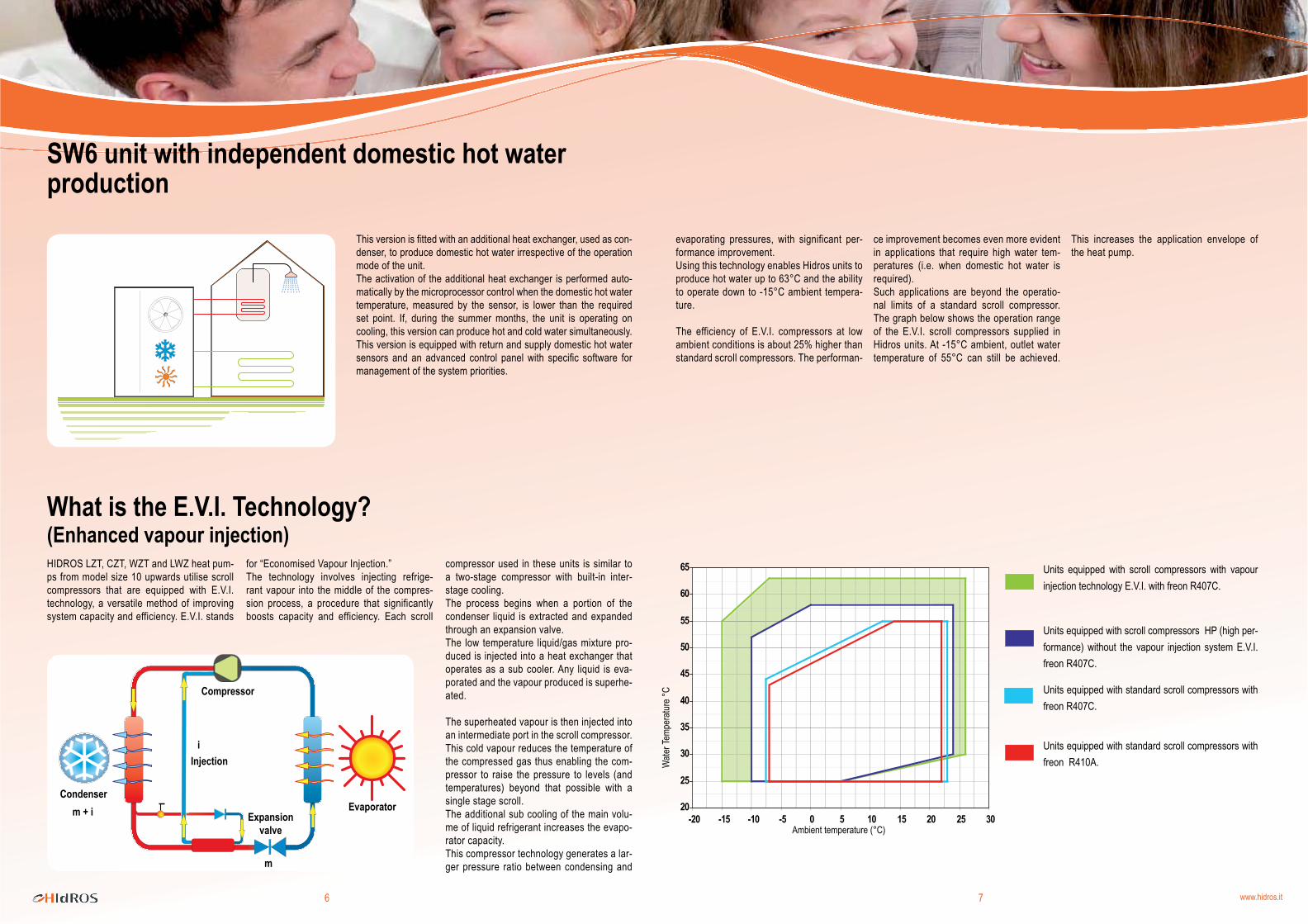
What is the E.V.I. Technology?(Enhanced vapour injection)HIDROS LZT, CZT, WZT and LWZ heat pum-ps from model size 10 upwards utilise scroll compressors that are equipped with E.V.I. technology, a versatile method of improving system capacity and efficiency. E.V.I. stands
for “Economised Vapour Injection.”The technology involves injecting refrige-rant vapour into the middle of the compres-sion process, a procedure that significantly boosts capacity and efficiency. Each scroll
compressor used in these units is similar to a two-stage compressor with built-in inter-stage cooling. The process begins when a portion of the condenser liquid is extracted and expanded through an expansion valve. The low temperature liquid/gas mixture pro-duced is injected into a heat exchanger that operates as a sub cooler. Any liquid is eva-porated and the vapour produced is superhe-ated.
The superheated vapour is then injected into an intermediate port in the scroll compressor. This cold vapour reduces the temperature of the compressed gas thus enabling the com-pressor to raise the pressure to levels (and temperatures) beyond that possible with a single stage scroll. The additional sub cooling of the main volu-me of liquid refrigerant increases the evapo-rator capacity. This compressor technology generates a lar-ger pressure ratio between condensing and
evaporating pressures, with significant per-formance improvement. Using this technology enables Hidros units to produce hot water up to 63°C and the ability to operate down to -15°C ambient tempera-ture.
The efficiency of E.V.I. compressors at low ambient conditions is about 25% higher than standard scroll compressors. The performan-
ce improvement becomes even more evident in applications that require high water tem-peratures (i.e. when domestic hot water is required). Such applications are beyond the operatio-nal limits of a standard scroll compressor. The graph below shows the operation range of the E.V.I. scroll compressors supplied in Hidros units. At -15°C ambient, outlet water temperature of 55°C can still be achieved.
This increases the application envelope of the heat pump.
This version is fitted with an additional heat exchanger, used as con-denser, to produce domestic hot water irrespective of the operation mode of the unit. The activation of the additional heat exchanger is performed auto-matically by the microprocessor control when the domestic hot water temperature, measured by the sensor, is lower than the required set point. If, during the summer months, the unit is operating on cooling, this version can produce hot and cold water simultaneously. This version is equipped with return and supply domestic hot water sensors and an advanced control panel with specific software for management of the system priorities.
Units equipped with scroll compressors with vapour injection technology E.V.I. with freon R407C.
Units equipped with scroll compressors HP (high per-formance) without the vapour injection system E.V.I. freon R407C.
Units equipped with standard scroll compressors with freon R407C.
Units equipped with standard scroll compressors with freon R410A.
m + i
i
m
SW6 unit with independent domestic hot water production
Ambient temperature (°C)
Wate
r Tem
pera
ture °
CCompressor
Injection
CondenserEvaporator
Expansion valve
8 www.hidros.it98 www.hidros.it9
A.C.S.VS1
VS1
1
2
3
4
SE
5
12
6
7
13
8
9
10
11
VS1
VS1
Bar
Bar
SE 13
10
9
8
47
6
1
2
3
5
11
8
1 4 7 10 13
2 5 8 11 14
3 6 9 12 15
LZT-15°C
+63°C
E.V.I.
C.O.P.≥4,1
10M 10T 14M 14T 21 26 36 46 52 72 82 92kW 9,6 9,6 13,9 13,9 19,6 26,5 37,4 44,7 52,1 74,7 89,4 106,3kW 2,3 2,3 3,4 3,2 4,5 6,4 8,4 10,0 11,8 18,1 22,0 26,2w/w 4,2 4,2 4,1 4,3 4,4 4,1 4,5 4,5 4,4 4,1 4,1 4,1kW 11,3 11,3 15,4 15,5 21,4 30,9 42,2 46,6 57,8 84,4 93,2 117,0kW 3,0 3,0 4,1 4,0 5,6 8,1 10,8 12,5 15,2 23,6 27,0 33,2w/w 3,8 3,9 3,8 3,9 3,8 3,8 3,9 3,7 3,8 3,6 3,5 3,5
20
30
40
50
60
70
- 20 - 10 0 10 20 30 40 50
Heat Pump Buffer Tank Heating Pump Zone Manifold Temperature Sensor
Hot Water Tank Heating Sensor Zone Pump Min Temp. Sensor
Hot Water Sensor Hot Water Pump Dehumidifier Controller
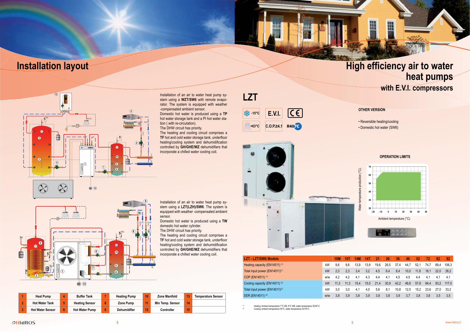
Installation of an air to water heat pump sy-stem using a WZT/SW6 with remote evapo-rator. The system is equipped with weather -compensated ambient sensor. Domestic hot water is produced using a TP hot water storage tank and a PI hot water sta-tion ( with re-circulation). The DHW circuit has priority.The heating and cooling circuit comprises a TF hot and cold water storage tank, underfloor heating/cooling system and dehumidification controlled by GH/GHE/WZ dehumidifiers that incorporate a chilled water cooling coil.
Installation of an air to water heat pump sy-stem using a LZT(LZH)/SW6. The system is equipped with weather -compensated ambient sensor. Domestic hot water is produced using a TW domestic hot water cylinder. The DHW circuit has priority.The heating and cooling circuit comprises a TF hot and cold water storage tank, underfloor heating/cooling system and dehumidification controlled by GH/GHE/WZ dehumidifiers that incorporate a chilled water cooling coil.
High efficiency air to water heat pumps
with E.V.I. compressors
OTHER VERSION
• Reversible heating/cooling• Domestic hot water (SW6)
(1) Heating: Ambient temperature 7°C DB, 6°C WB, water temperature 35/30°C. (2) Cooling: ambient temperature 35°C, water temperature 23/18°C.
OPERATION LIMITS
Wate
r tem
pera
ture p
rodu
ction
(°C)
.
Ambient temperature (°C).
LZT - LZT/SW6 ModelsHeating capacity (EN14511) (1)
Total input power (EN14511)(1)
COP (EN14511) (1)
Cooling capacity (EN14511) (2)
Total input power (EN14511)(2)
EER (EN14511) (2)
Installation layout
10 www.hidros.it1110 www.hidros.it11
WZT-15°C
+63°C
E.V.I.
C.O.P.≥4,1
20
30
40
50
60
70
- 20 - 10 0 10 20 30 40 50
Mod. WZT 06 ÷ 08
Mod. WZT 10 ÷ 92
LWZ - WWZ-15°C
+63°C
E.V.I.
C.O.P.≥4,1
20
30
40
50
60
70
- 20 - 10 0 10 20 30 40 50
14T (3) 21 (3) 26 36 52 72 82 92kW 13,9 19,6 26,5 37,4 52,1 74,7 89,4 106,3kW 3,2 4,5 6,4 8,4 11,8 18,1 22,0 26,2w/w 4,3 4,4 4,1 4,5 4,4 4,1 4,1 4,1l/h 1100 1500 1800 2700 3650 5350 6250 7500kW 15,5 21,4 30,9 42,2 57,8 84,4 93,2 117,0kW 4,0 5,6 8,1 10,8 15,2 23,6 27,0 33,2w/w 3,9 3,8 3,8 3,9 3,8 3,6 3,5 3,5
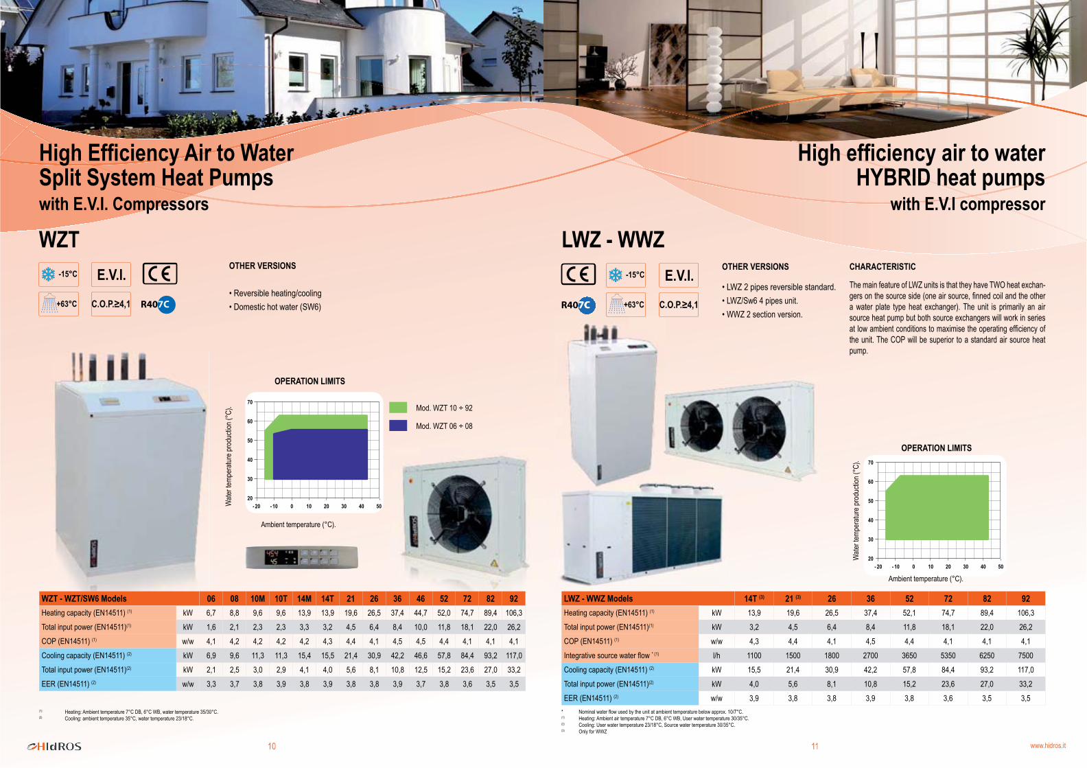
06 08 10M 10T 14M 14T 21 26 36 46 52 72 82 92kW 6,7 8,8 9,6 9,6 13,9 13,9 19,6 26,5 37,4 44,7 52,0 74,7 89,4 106,3kW 1,6 2,1 2,3 2,3 3,3 3,2 4,5 6,4 8,4 10,0 11,8 18,1 22,0 26,2w/w 4,1 4,2 4,2 4,2 4,2 4,3 4,4 4,1 4,5 4,5 4,4 4,1 4,1 4,1kW 6,9 9,6 11,3 11,3 15,4 15,5 21,4 30,9 42,2 46,6 57,8 84,4 93,2 117,0kW 2,1 2,5 3,0 2,9 4,1 4,0 5,6 8,1 10,8 12,5 15,2 23,6 27,0 33,2w/w 3,3 3,7 3,8 3,9 3,8 3,9 3,8 3,8 3,9 3,7 3,8 3,6 3,5 3,5
High Efficiency Air to Water Split System Heat Pumps with E.V.I. Compressors
OTHER VERSIONS
• Reversible heating/cooling• Domestic hot water (SW6)
OPERATION LIMITS
Wate
r tem
pera
ture p
rodu
ction
(°C)
.
Ambient temperature (°C).
OTHER VERSIONS
• LWZ 2 pipes reversible standard.• LWZ/Sw6 4 pipes unit.• WWZ 2 section version.
OPERATION LIMITS
LWZ - WWZ ModelsHeating capacity (EN14511) (1)
Total input power (EN14511)(1)
COP (EN14511) (1)
Integrative source water flow * (1)
Cooling capacity (EN14511) (2)
Total input power (EN14511)(2)
EER (EN14511) (2)
* Nominal water flow used by the unit at ambient temperature below approx. 10/7°C.(1) Heating: Ambient air temperature 7°C DB, 6°C WB, User water temperature 30/35°C. (2) Cooling: User water temperature 23/18°C, Source water temperature 30/35°C. (3) Only for WWZ
The main feature of LWZ units is that they have TWO heat exchan-gers on the source side (one air source, finned coil and the other a water plate type heat exchanger). The unit is primarily an air source heat pump but both source exchangers will work in series at low ambient conditions to maximise the operating efficiency of the unit. The COP will be superior to a standard air source heat pump.
CHARACTERISTIC
WZT - WZT/SW6 ModelsHeating capacity (EN14511) (1)
Total input power (EN14511)(1)
COP (EN14511) (1)
Cooling capacity (EN14511) (2)
Total input power (EN14511)(2)
EER (EN14511) (2)
(1) Heating: Ambient temperature 7°C DB, 6°C WB, water temperature 35/30°C. (2) Cooling: ambient temperature 35°C, water temperature 23/18°C.
High efficiency air to water HYBRID heat pumps
with E.V.I compressor
Wate
r tem
pera
ture p
rodu
ction
(°C)
.
Ambient temperature (°C).
12 www.hidros.it1312 www.hidros.it13
WZH - WDH
30
40
50
60
70
- 10 0 10 20 30 40 50
05 07 09 011 013 015 020 030 039 045 050 060 070 080kW 7,4 10,0 12,5 14,4 17,8 20,9 27,0 38,0 48,2 58,7 67,9 75,8 83,7 101,7w/w 1,5 1,9 2,4 2,7 3,2 3,8 5,2 7,1 5,1 5,1 5,3 5,2 5,2 5,2kW 8,2 11,1 13,9 15,9 19,8 22,8 29,0 41,9 56,2 70,2 82,8 86,9 101,8 123,1w/w 1,7 2,0 2,5 2,8 3,5 4,1 5,9 7,9 5,7 5,8 6,0 5,5 5,7 5,8
90 110 120 130 152 162 144 164 190 210 240 260 300 320kW 118,4 135,2 152,3 169,5 189,1 208,7 185,4 203,4 236,8 270,3 304,7 339,1 378,2 420,3w/w 5,3 5,3 5,3 5,3 5,4 5,4 5,2 5,3 5,3 5,3 5,3 5,3 5,4 5,5kW 143,4 157,0 185,6 207,3 222,5 253,6 214,7 241,3 297,5 340,2 385,4 430,3 485,2 540,0w/w 5,9 5,6 5,9 5,8 5,7 6,0 5,4 5,6 6,0 6,0 6,0 6,0 6,1 6,3
GHE
GHE
25 50l/24h 30,1 61,8
W 1380 2820% 90% 90%W 340 480
m3/h 0 ÷ 130 0 ÷ 250m3/h 130 ÷ 260 250 ÷ 500
Ground source heat pumps
OTHER VERSIONS
• Heating only• Reversible heating/cooling• Reversible version heating/cooling with independent DHW circuit• Free cooling
Dehumidifiers with high efficiencyheat recovery
Contact the company
Normal operation
(1) Heating: condenser water temperature in/out 30/35°C; evaporator water temperature in/out 10/7°C..unit without pressostatic valve.(3) Cooling: data are refferred to unit with pressostatic valve. : evaporator water in/out 23/18°C, condenser water temperature in/out 30/35°C.
WZH - WDH ModelsHeating capacity (EN14511) (1)
COP (EN14511) (1)
Cooling capacity (EN14511) (2)
EER (EN14511) (2)
WZH - WDH ModelsHeating capacity (EN14511) (1)
COP (EN14511) (1)
Cooling capacity (EN14511) (2)
EER (EN14511) (2) 1) Performances refer to the following conditions: Amb. Temp. 26°C; 65% RU; Fresh Air 35°C; 50% RU; Fresh air flow 130 m3/h; Water IN 15°C, Water Flow 250 l/h2) Performances refer to the following conditions: Amb. Temp. -5°C; 80% RU; Fresh Air 20°C; Maximum fresh air flow3) Sound Pressure level measured at 1 mt from the unit in free field conditions according with ISO 9614. 4) Sound Power level according to ISO 9614
• High efficiency cross-flow heat recovery• Dehumidification Refrigeration• Integration of cooling and heating• Exhaust Fan with EC motor• Modbus interfaceOPERATION LIMITS
Wate
r tem
pera
ture p
rodu
ction
(°C)
.
Ambient temperature (°C).
Supply air flow
Recirculating Air
Supply air flow Supply
air flowExhaust air
intake
Exhaust air intake
Exhaust air intake
Exhaust Air
Fresh Air
GHE Models Dehumidification capacity (from the net hygroscopic content of the external air) (1)
Total cooling Capacity (latent + sensible) (1)
Heat recovery winter efficiency (2)
Compressor input power (1)
Fresh air flow Supply air flow
14 www.hidros.it1514 www.hidros.it15
UTH-UTHZ
SBA LSA-CSA
LDA-CDA-LGK
WSA-WDA-WVK
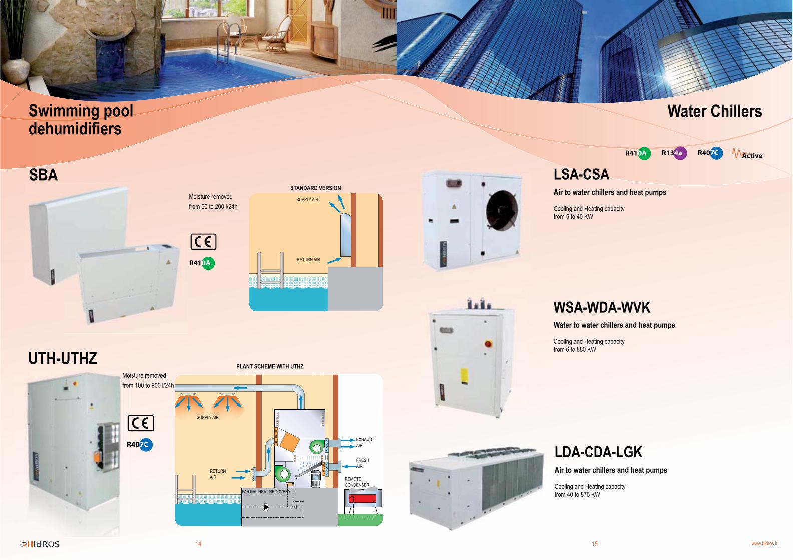
Swimming pool dehumidifiers
SUPPLY AIR
RETURN AIR
EXHAUST AIR
FRESH AIR
REMOTE CONDENSER
PARTIAL HEAT RECOVERY
Moisture removedfrom 100 to 900 l/24h
Moisture removedfrom 50 to 200 l/24h
PLANT SCHEME WITH UTHZ
STANDARD VERSION
SUPPLY AIR
RETURN AIR
Air to water chillers and heat pumps
Cooling and Heating capacityfrom 5 to 40 KW
Air to water chillers and heat pumps
Cooling and Heating capacityfrom 40 to 875 KW
Water to water chillers and heat pumps
Cooling and Heating capacityfrom 6 to 880 KW
Water Chillers

HIDROS S.p.A.Via dell ' industria, 5 - 35020 Brugine (PD)
Tel +39 049 9731022 - Fax +39 049 5806928www.hidros.it - [email protected]
P.IVA e C.F 03598340283 - R.E.A. PD-322111REG. IMP. PD 0359834 028 3 - VAT NUMBER: IT 03598340283 - CAPITALE SOCIALE € 1.200.000,00 i.v.
Valencia
Brugine
ColoniaRaamsdonksveer
Belfast
REG. IMP. PD
Technical data shown in this booklet are not binding. HIDROS S.p.A. shall have the right to introduce at any time whatever modifications necessari to the improvement of the product.
Production Units Sales Offices Distributors