
Heat Mat Underfloor Heating Mat Instructions
9
Instructions and Fitting Guide Version 3 – 2016 Call 01444 247020 for Technical Support Underfloor Heating – made easy... Heating Mats Quick guide to installation Page 2 Homeowner guide Page 7
Transcript of Heat Mat Underfloor Heating Mat Instructions

Instructions and Fitting Guide
Version 3 – 2016
Call 01444 247020 for Technical Support
Underfloor Heating – made easy...
Heating Mats
Quick guide to installation Page 2
Homeowner guide Page 7
Heat Mat Limited accept no liability, either express or implied, for any consequential losses incurred as result of a Heat Mat system installation that does not conform to the following installation instructions.
Do’s• Thoroughly read this guide before
starting installation
• Ensure that all heating elements and joints are encapsulated within tile adhesive or levelling compound and fitted beneath the floor covering
• Use a multi-meter to test the mat, before, during and after covering (see page 4)
• Plan the layout of the mats before fitting them. We recommend taking a photograph of your system layout before tiling for future reference
• Connect multiple mats in parallel
• Consider thermally insulating the sub-floor before installing the underfloor heating system
• Use a Heat Mat thermostat to control the system
• Ensure that all electrical works conform to Part ‘P’ of the Building Regulations and current IEE Wiring Regulations
• Ensure that a suitably qualified electrician makes the final electrical connections and approves the installation
• Ensure the system is protected by a suitable RCD device (30mA)
• Ensure the ambient temperature is above 5ºC when installing the system
• Remove cable from the mesh to help fit the heating system in awkward areas
• Check that you have the correct heater or combination of heaters for your chosen area before commencing your installation, (see page 4 for details)
Don’ts• Cut, shorten, strain or cross the
heating cables
• Bend the joint between the element and cold tail
• Supply power to the heater until the mat has been fully covered and the wet trade has been allowed to fully dry out
• Lay cables closer than 40mm to each other or conductive parts; coldtail connections and the end terminations must be 80mm away from heating cable and each other
• Install the mats in walls or ceilings (unless prior approval has been given by Heat Mat’s Technical Team)
• Install the floor sensor close to other heat sources such as hot water pipes
• Begin covering with tile adhesive or levelling compound until the mat is in place and has been tested with a multi-meter (see page 4)
• Leave any sections of the heating cable or connections in the open air or beneath fixtures and fittings when installation is completed
• Use the heating system to help to dry out the wet trade
• Place tape over the coldtail connection or end termination
• Spot dab tile adhesive when fitting tiles above the heating system
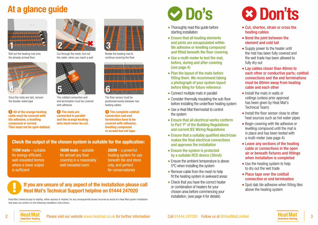
At a glance guide
Roll out the heating mat onto the already primed floor
Cut through the mesh, but not the cable, when you reach a wall
Rotate the heating mat to continue covering the floor
1 2 3
Once the mats are laid, remove the double-sided tape
The coldtail connection and end termination must be covered with adhesive
The floor sensor must be positioned evenly between two heating cables
4 5 6
If you are unsure of any aspect of the installation please call Heat Mat’s Technical Support helpline on 01444 247020
All of the orange heating cable must be covered with tile adhesive, a levelling compound or screed. Tiles must not be spot-dabbed.
The mats are connected in parallel and the orange heating wire must never be cut.
The complete coldtail connection and end termination have to be covered with adhesive, levelling compound or screed but not tape.
Check the output of the chosen system is suitable for the application:
110W mats – suitable for energy-efficient, well-insulated homes where a lower output is sufficient
160W mats – suitable for almost any floor covering in a reasonably well insulated room
200W – a powerful heating system for use beneath tile and stone only, and perfect for conservatories
2 3Please visit our website www.heatmat.co.uk for further information Call 01444 247020 Follow us at @HeatMatLimited

Coverage, resistance and testingCalculating coverage:Although 100% coverage with heating mats is achievable, a border of 20-40mm is recommended around the perimeter of the room as the heating cables should not touch the walls. With kickboards we recommend going as close as possible to the kickboard with the heating system to ensure that section of the floor where people often stand is heated.
In normal circumstances we would recommend deducting between 5 and 10% from the total free floor space that you wish to heat, to give you the square metres of heating mat that you should install (for instance using a 7.7m2 mat in a room with free floor space of 8.5m2). Our recommendation is to deduct 10% for fitting space in rooms up to 15m2, 7% for rooms between 16m2 and 25m2, and 5% fitting space for larger rooms.
Multiple mats can be combined to provide a good coverage in a room, but the mats must always have the same Wattage output per square meter.
Thermal resistance of coveringsThe material used to cover the heating cable must have a density of at least 1,500kg/m3 and a minimum heat transmission of 1W/m K. All normal tile adhesives, leveling compounds and screeds conform to this standard. The thermal resistance (insulation) between the heating system and the room must not have an insulation value higher than 0.125 m2K/W (in other words the layers above the heating system must not prevent the heat from rising into the room). Some typical insulation values for common floor coverings are listed below:
Tiled, stone and thin vinyl floors up to .............................................................................................................. 0.035 m²K/W
Linoleum floors and thick vinyl floors up to ................................................................................................... 0.040 m²K/W
Hessian backed carpets with low Tog underlays up to............................................................................ 0.125 m²K/W
Parquet and laminate floors up to 18mm thick up to ............................................................................... 0.125 m²K/W
Wood fibre floors and rubber backed carpets from .................................................................................. 0.175 m²K/W
Wood fibre and rubber backed carpets are not suitable for use with conventional underfloor heating systems. Speak to Heat Mat’s Technical Support Team to discuss your options if you need to heat these surfaces.
Testing your heating mat with a multi-meter• Test your heating mat with a multi-meter
before unwrapping to confirm you have received it in working order.
• The black coldtail is double insulated and carries an earth screen (silver braid), live and neutral wires.
• Exposing the ends of these wires will allow the continuity tests to be carried out with a functional multi-meter.
• This test should also be done before, during and after tiling.
• At no point should any cable be connected to a power supply to test it.
Tests• Live to neutral = ohms value as in table on page 15
• Live to earth and neutral to earth = both infinity.
If your tests do not conform to the expected results please contact Heat Mat’s Technical Support Team.
Installation instructions
Floor prep • Before laying the heating mats the base must
be solid, level and dust free.
• If the base is badly insulated and constructed of a variety of materials you should use insulation boards to ensure the system to heats up evenly.
• We always recommend using a structural insulation board on badly insulated bases to improve the systems energy-efficiency. Soft insulation without a concrete facing cannot be used.
• Insulation boards should always be installed following the manufacturers instructions and reinforcement tape must be used to secure the joins.
• A wooden floor base should be suitably secured to eliminate movement – 6mm and 10mm structural insulation boards can be used for this purpose.
• Before laying the mats the base should be primed with a primer compatible with the levelling compound or tile adhesive you intend to use.
Installing the Heating MatsBefore you start laying the heating mats
• When installing the mats and walking on them you should wear soft-soled shoes.
• Each mat must be tested with a multi-meter prior to installation commencing.
• Before you start to roll out your mats take the time to plan the layout of the heating mat/s. As the mats are laid in parallel the cold-tails of all mats must be able to reach the connection point (usually the thermostat).
• One or two heating mats can be wired directly into the back of the thermostat, larger numbers of mats will require a separate connection box. If the system exceeds 16Amps a contactor will be required to power the system.
How to manipulate the mats
• The mat works on a cut-and-turn principle meaning you can cut the mesh of the mat, which allows you to flip the mat around and start laying it in an alternative direction.
• In awkward areas the heating cable can be removed from the fibreglass mesh and laid loosely to ensure the heating system fits your room. When doing this try to keep the space between the cables similar to that on your mat to maintain an even output across the floor.
• Any loose cables should be secured to the floor with double sided tape or a hot glue gun.
• If the mats are slightly too long or too short you can get them to fit correctly by cutting the mesh between each run of cable. The runs of cable can then be laid slightly further apart or closer together to fit the area.
• Cables should never be less than 40mm apart whether they are on the heating mat or laid loosely.
• If you find you have to lay the heating cables less than 50mm apart, or more than 150mm apart for more than 20% of the floor area the mats are not the right size for the room.
• The heating cable cannot be cut to shorten it under any circumstances and cables must never cross.
Please read pages 2 & 3 before
reading these instructions including the
Do’s and Don’ts 1 2
4 5Please visit our website www.heatmat.co.uk for further information Call 01444 247020 Follow us at @HeatMatLimited

How to position the mats
• The mats can be laid in any direction in a room, but it makes sense to work out if one direction provides better coverage than the other. For instance if a room is 3.6 x 2.4m you could get 7 runs of mat 2.3m long running the mats length ways or 4 runs of mat 3.5m long if you ran the other way. The first option provides a better coverage of the floor.
• If you only have one mat, start fitting from one corner of the room (if the cold-tail does not reach back to the connection point you can strip some heating cable from the mat to allow it to reach).
• Roll out the mat onto the floor mesh side up (fig 2) until you reach the wall or an obstruction and cut-and-turn (fig 3) the mat to continue laying it.
• Repeat this until you have covered the floor (fig 4).
• If you’re using multiple mats we recommend fitting the largest mat first. We recommend rolling the mat out to the furthest point of the room and then working the mat back towards your starting point. You must make sure you do not “paint yourself into a corner” or leave isolated areas unheated.
• If you have a small amount of mat left over when you have covered the floor you can cut the mesh from side to side between each run of heating cable, and shuffle the mat together shortening the distance between each cable run to use up the excess mat. Alternatively, if you don’t have quite
enough heating mat you can cut the mesh and space the cable runs slightly further apart to cover a larger area.
• Once all mats are in position, remove the backing from the adhesive tape attached to the underside of your mat/s and secure to your base (fig 5). Any
loose cable or mesh can be secured by using a hot glue gun or masking tape. Walking over the mats with soft-soled shoes will help the tape stick to the floor.
• The cold-tail connection and end termination must be kept straight and laid flat in a position that will be beneath the final floor covering. These may have to be chased into the sub-floor and can be held down with double-sided tape laid beneath them. These sections must not be covered with tape and must be fully encased by tile adhesive or levelling compound (fig 6).
• A suitable floor sensor (usually supplied with the thermostat) should be installed to monitor the floor temperature.
• This must be placed a minimum of 300mm into the heated floor area. This should be equally spaced between the heating cables and must not cross the heating cable at any point (fig 7).
• The floor sensor can be encapsulated within the tile adhesive or levelling compound used to cover the heating mat, alternatively a closed-end flexible conduit can be positioned onto the floor base to house the sensor.
Continued on page 11
3 4
A. Robust PVC (Y) outer insulation
B. 100% aluminium earth shield for safety
C. High load earth drain wire
D. Fibreglass reinforcement cable for tensile strength
E. Fluoropolymer insulation rated to 200ºC
F. Litzer style twin spiral wound resistance wires
Only Heat Mat cables include:
Living with your new Heat Mat electric underfloor heating systemA Heat Mat underfloor heating system is a fantastic investment in your home’s comfort adding a luxurious feel to your floors.
All of our heating mats are hand-made in Denmark, using high quality cables and meeting the best possible safety standards. Our systems are independently approved, CE marked and guaranteed for life providing extra peace of mind.
How much does electric underfloor heating cost to run?Although some people believe underfloor heating (UFH) is expensive to run, the reality is that both the initial installation fee and the ongoing running costs can represent great value for money. It costs less than 10p to run 1m2 of underfloor heating at maximum power for six hours.
Running costs of your Heat Mat system will depend on:
• How well insulated the room is
• The output of your heating mats (110W are lower output, 160W are standard and 200W are the highest and only for use under tile and stone in less energy-efficient rooms)
• Your energy tariff
• How you program your thermostat (see the next page for advice on this)
*These figures are based on Heat Mat’s 160W/sqm heating mats laid directly onto 10mm Heat Mat Thermal insulation boards with porcelain tiles above in a property meeting the latest Part L Building Regulations standard. The energy cost of 8.610p kWh is based on Sainsbury’s Energy SE Fixed Price June 2017 deal. Prices are correct as of June 2016. Source – www.uswitch.com For more details on assumptions see www.heatmat.co.uk/running-costs
Examples of monthly running costs*
Room Type
Heated Area m2
AM Heating Hours
PM Heating Hours
Monthly cost
En-suite 2.5 2 1 £1.82
Bathroom 3.5 2 2 £3.16
Kitchen 6 0 2 £4.39
Lounge 10 1 3 £10.80
Conservatory 12 0 4 £16.89
7Call 01444 247020 Follow us at @HeatMatLimited
Homeow
ner Guide Pull out and keep
6 Please visit our website www.heatmat.co.uk for further information

Ensuring the thermostat is set up correctlyYour thermostat is supplied with fitting instructions and a ‘Quick Start Guide’ (NGTouch only). You can also download further information from our website: http://www.heatmat.co.uk/help-support/instructions/
Ensure the thermostat is set up correctly to be as efficient as possible
1. Your heating schedule The NGTouch allows you to program a series of ‘events’ per day to reflect your lifestyle. You can set different times and temperatures for different activities throughout the day e.g. wake up/getting ready for work first thing in the morning to overnight. Instructions on how to do this are included with your thermostat.
2. Set the correct target temperatureIf your system is running on air temperature then a target temperature of 20ºC/68ºF would normally result in a warm room. If your system is running on floor temperature then a target temperature of 30ºC/86ºF is normally required for a warm floor.
3. Monitor air or floor If your thermostat is in the same room as the heating system we recommend setting it to room sensor with floor limitation. If it is outside of the room it should always be set to floor sensor (floor limitation should always be used for electric underfloor heating installations).
The NGTouch has a number of features to make managing your UFH easy.
Comfort mode – You set the temperature and the time. This is a temporary override to the heating schedule you have programmed, allowing you to adjust the temperature to suit the conditions at the time e.g. turn it up for a couple of hours.
Boost mode – A short burst of heat. Boost allows you to switch the heating onto maximum power for an hour to rapidly heat the room and create a cosy environment.
Holiday mode – Walk into a warm home after your holiday. This mode allows you to program the start and end dates of your holiday, maintaining an even floor temperature of around 5ºC for frost protection while you’re away. The heating is activated in time for your return so you walk back onto warm floors.
Frost protection – Stop the floor from freezing. Frost protection turns the heating off but prevents the floor from freezing by maintaining a steady, very low temperature of 5ºC. This could be used in a holiday home for example.
Eco mode – Allows you to save energy in between heating ‘events’. This function lets you quickly turn off the heating until the next ‘event’. Despite running on your normal daily schedule, Eco mode, pauses the heating system to save energy. It can be found under the Advanced settings menu.
Comfort Mode
Boost Mode
Holiday Mode
Easy Energy Saving
Eco Mode
Frost Protection Mode
What to avoidThermal blocks• Avoid thermal blocks on the floor as they can
cause the floor to get very warm beneath them, wasting energy- beware of thermal blocking, we do not recommend the use of large flat based pieces of furniture, rubber backed carpets, 70’s bean bags, wet washing left on floors, large dog beds on heated floors as these items trap the heat by preventing air movement.
• Never thermally block where the floor sensor is as it will lead to your thermostat switching off the heating system too early.
• Never drill down into a floor that contains a heating system if you can avoid it. If you must drill into a heated floor (for instance to install a door stop) contact Heat Mat for details of their thermal imaging sheets, which can show the location of heating cables (although they can’t be used to locate the floor sensor).
Thermostats• Avoid obstructing the wall-mounted thermostat
as this has an internal air temperature sensor and blocking air movement around the thermostats may cause an incorrect temperature to be read.
• Ensure the thermostat is not exposed to direct sunlight.
• Do not use water to clean the wall-mounted thermostat! Use a soft cloth with a suitable plastic cleaner.
• The system will have a floor temperature sensor installed beneath the wall mounted thermostat Avoid placing objects that may cause a heat build-up above this sensor as this will switch your heating system off prematurely.
• Always ensure that your heating system is correctly programmed to eliminate energy wastage, contact our technical team on 01444 247020 for assistance.
Floor construction and walls• Avoid disturbing the floor construction,
if door stops or similar items are to be installed consider use a Heat Mat cable trace sheet which will be able to show where cables are installed and enable drilling to be carried out without damaging the heating system.
• Do not expose the floor finish to standing water for long periods of time, although mopping your tile or stone floor is fine.
• Do not drill into the wall around or directly beneath the wall mounted thermostat as there will be 230V power cables present.
• If the floor is flooded then the floor must be fully dried out before the system is used, it must not be used to dry out the floor. The system should also be electrically tested before use again.
Other things to consider • If a system or thermostat appears to
not be working correctly or is damaged during installation we offer full support. Call our technical team on 01444 247020 for assistance.
• If a system has been damaged during or subsequent to installation Heat Mat can arrange for an independent engineer to visit, establish why the system is not working, and repair the cable in situ. Please contact Heat Mat for more details.
Calling us for support programming itOur technical support team is available from 8.30am-5.30pm Monday – Friday to assist with any queries.
Call 01444 247020 or request a call back via our website www.heatmat.co.uk
8 9Please visit our website www.heatmat.co.uk for further information Call 01444 247020 Follow us at @HeatMatLimited
Hom
eow
ner G
uide
P
ull o
ut a
nd k
eep Hom
eowner Guide Pull out and keep

• The sensor cable can be extended if required up to 100m using a twin sheathed high-temperature resistant PVC cable.
• The floor sensor should not be fitted in areas affected by other heat sources such as hot water pipes and radiators or in an area that will be covered at a later date with items such as rugs or flat-bottomed furniture, as this will prevent the system from operating correctly.
• Test the heating system again with a multi-meter prior to covering.
• Take a photograph of the layout of your system and the position of the floor sensor for future reference.
• If the floor covering is not being fitted immediately protect the heater/s by covering with cardboard or carpet and restrict any traffic above the cable to a minimum. After removing the protective covering before laying the final floor covering you should test the cables again before proceeding.
Laying the final floor covering
• Take care not to crush or damage any heating cables during installation of the floor covering, even a small nick in the outer insulation of the heating cable can lead to system failure over a long period of time.
• If the cable is damaged a repair kit should be used to fix the damage.
• We recommend that flooring installers regularly check the resistance and continuity of the cable with a multi-meter during installation. Alternatively Heat Mat’s Cable Safe Monitor can be used to provide a warning of any damage to the elements.
• For installing beneath standard tiles or stone we recommend skimming the mats with a 3mm layer of flexible cementitious tile-adhesive or using a latex screed to cover the cables. Once this layer has hardened you can begin tiling.
• Tiles must always be fully bedded in and must not be laid with dabs of adhesive.
• Care must be taken when tiling and cleaning out grout lines not to cut or catch the heating cable.
• If installing mosaic tiles, carpets, vinyl and bonded wood coverings a layer of 12mm of cementitious flexible levelling compound must be used to cover the cables (Heat Mat can supply this).
• When laying tile adhesive or levelling compound a plastic notched trowel should be used to push the adhesive along the cables rather than against them.
• The underfloor heating must never be used to ‘dry-out’ the tile adhesive or levelling compound. The system must never be turned on until all adhesives and compounds are completely dry.
5 6 7
Typical bathroom layout
The ultra-thin heating mat has been manufactured and supplied in the European Union by Heat-Com a/s/Heat Mat Limited, and the following Warranty is supplied in accordance with the general product liability rules, as stated in Directive 85/374/CEE, and all relevant national laws. You are provided with an initial fifteen year warranty on the ultra-thin heating mat for eventual defects in material. Details and evidence of defects has to be presented to Heat-Com, Heat Mat or an authorised UK or Ireland distributor for approval.
When your warranty is invoked, your damaged product will either be repaired or replaced free of charge to yourself.
Your warranty does not cover the following:
• Any faults caused by misuse
• A system which has not been installed in accordance with the manufacturer’s guidelines
• Any other subsequential or consequential damages. To provide clarification, these damages could include the cost of repairs to walls, floors, wiles; professional fees; utility expenses. We would however pay for any reasonable damages which are a foreseeable consequence of Heat Mat’s negligence
• Any system that had not been paid for in full
Heat-Com a/s/Heat Mat Limited are covered by an international insurance covering warranty payments.
In addition to the above 15 year warranty, Heat Mat offer a lifetime extension to the above warranty on your ultrathin heating mat. To be covered by this extra warranty in addition to the above stipulations you must also:
• Register your product at www.heatmat.co.uk/warrantyregistration within 90 days of purchase
• Be able to provide your proof of purchase of the system, a normal retail invoice/receipt is sufficient for this purpose
• Ensure the system has been installed in accordance with Heat Mat’s installation guidelines and it must be protected by a suitable RCD
• Ensure that all installation work is compliant with current IEE wiring regulations and installations must comply with Part ‘P’ of the Building Regulations. You should retain your Part ‘P’ certificate as proof of this
If the above stipulations have been followed, Heat Mat will provide a lifetime warranty once the original fifteen year warranty expires for the ultra-thin heating mat. This warranty runs for the life of the floor covering above the original installation. This warranty covers manufacturing defects in the ultra-thin heating mat supplied. Details and evidence of defects has to be presented to Heat Mat or an authorised UK or Ireland distributor for approval. When your warranty is invoked, your damaged product will either be repaired or replaced free of charge to yourself.
The repair or replacement of your system is the only remedy available to you under these warranties. None of the above warranties affect your statutory rights. Heat-Com a/s and Heat Mat Limited will in no event be liable for consequential losses or secondary charges including but not restricted to the cost of replacing or repairing floor coverings, any costs associated with utility expenses or running costs, professional fees relating to trades peoples’ subsequent work or any other damage caused to material items.
Heat Mat Lifetime WarrantyCongratulations on your purchase of a Heat Mat electric underfloor heating system.
11Call 01444 247020 Follow us at @HeatMatLimited10 Please visit our website www.heatmat.co.uk for further information
Hom
eow
ner G
uide
P
ull o
ut a
nd k
eep

Electrical connections Wiring can now be completed but no power should be applied to the system until the adhesive, grout and/or levelling compound is completely dry.
All work must comply with current IEE wiring regulations and installations must comply with Part ‘P’ of the Building Regulations. Consult your Local Authority Building Control department regarding their requirements for certification or check with an electrician qualified to issue Part ‘P’ certification regarding your individual installation.
The heating mat/s have to be wired into a thermostat with floor temperature limitation. Please see the separate instructions in your Heat Mat thermostat box.
Run the coldtail connection and floor sensor cable in separate plastic conduit or trunking from your heated floor to the thermostat position.
Up to 2 heating mats can be wired straight into the thermostat. A connection box will be required if installing 3 or more heating mats. Ensure that multiple mats are wired in parallel, not in series.
The mains power supply must be protected by a suitable RCD (30mA and up to 4.8kW).
The thermostat should be connected to the power supply via a suitably rated fused spur or circuit breaker.
Heat Mat’s thermostats are rated 16 Amp and if the total loading from a combination of heating mats exceeds this, we would recommend the installation of a suitable rated contactor which would allow the heating system to be run through a single thermostat for ease of control.
Please check the IP rating of your chosen thermostat to ensure it meets with the current wiring regulations for its chosen installation position.
If the thermostat is placed outside the room to be heated, or inside a cupboard, the thermostat will have to be reprogrammed (when first switched on) to only monitor the floor sensor that has been placed into the heated floor space.
Some of Heat Mat’s thermostats are IP21 rated, and the heating mats are IPX7 rated, which means systems can be installed in bathrooms and other ‘wet areas’ and if a suitable zone is available the thermostat can also be placed in the bathroom.
Remember: If you are unsure how to proceed at any stage of the installation process, please contact Heat Mat Technical Support on 01444 247020 for guidance.
Living with your Underfloor Heating System To ensure that your system works to its full capacity for the lifetime of the flooring, please ensure that thermal blocking is avoided above the heating system.
Thermal blocking occurs when the heat produced by the system warms the floor surface but is then trapped and has no way of escaping from the surface of the floor. This can cause the system to overheat in the thermally blocked area and, in extreme cases, affect the integrity of the floor covering and heating system.
Thermal blocking is not usually a problem within floors where the system has been covered with levelling compound or tile adhesive and tiles, as these coverings are efficient transmitters of heat themselves and will spread the heat around any thermal block. Thermal blocking has a greater chance of occurring in situations with a carpeted, wooden or laminate floor finish that do not utilise a levelling compound as these coverings do not transmit heat as effectively.
Basic wiring diagram
Typical Wiring System• All electrical works must be carried out by a
certified electrician.
• A suitable RCD protection must be incorporated in this system.
• If the ampage of the thermostat is exceeded by your chosen system,a contactor or similar device will be required. All thermostats and the fused spur must be of a two-pole design with a minimum opening between the contacts of 3mm. For full BEAB system approval you must use a suitable Heat Mat BEAB approved thermostat.
• The heating cables must not be cut or cross each other or other wiring.
• The cold tail joint must be kept straight and located beneath the final floor covering and must be thoroughly encased in tile adhesive or levelling compound.
• Please consult your electrician to discuss your individual requirements.
• The thermostat is designed to fit into a single gang box, and two sections of conduit should lead from the thermostat down to the floor; one for the power leads for the heating mats, and one for the floor sensor.
Please see the back page of this fitting guide for the required information for the distribution board.
It is a legal requirement that this information is completed
and is displayed near the relevant distribution board.
12 13Please visit our website www.heatmat.co.uk for further information Call 01444 247020 Follow us at @HeatMatLimited

Technical Specification
Product code Coverage (m2)
Length (m)
Wattage (W)
Resistance (Ohms) +/- 10%
All Heat Mat underfloor heating mats are 0.5m wide
PKM-200-0060 0.6 1.2 130W 442 Ω
PKM-200-0100 1.0 2.0 208W 277 Ω
PKM-200-0160 1.6 3.2 310W 186 Ω
PKM-200-0200 2.0 4.0 405W 142 Ω
PKM-200-0260 2.6 5.2 512W 113 Ω
PKM-200-0280 2.8 5.6 576W 100 Ω
PKM-200-0350 3.5 7.0 719W 80 Ω
PKM-200-0420 4.2 8.4 854W 67 Ω
PKM-200-0540 5.4 10.8 1083W 53 Ω
PKM-200-0060 6.0 12.0 1196W 48 Ω
PKM-200-0670 6.7 13.4 1353W 43 Ω
PKM-200-0750 7.5 15.0 1504W 38 Ω
PKM-200-0890 8.9 17.8 1769W 33 Ω
PKM-200-0990 9.9 19.8 1973W 29 Ω
200 W/m2 Technical Specification
Technical Data:General Construction: Dual conductor wire with earth
Voltage: 240 Vac – 50Hz
Maximum Load: 20 W/m
Maximum Cable Temperature: 90 ºC
Approvals: CE Marked, SEMKO and BEAB system approved
Wire Thickness: 2.7mm to 3.2mm depending on Ohm Value
Cable Flexibility: Minimum allowable cable radius is 18mm
Power Range: 120W – 1973W
Approved in accordance with: EN 60335-1:1998, EN60335-2-17:1999, IEC 60730
Construction:Thermal Conductor: 2 x resistance wire insulated with fluoropolymer (FEP 7Y) tested to 200ºC
Outer Insulation: PVC (Y) tested to 90ºC
Reinforcement Materials: Fibreglass strands
IP Rating: IPX7
Reinforcement Mesh: Fibreglass mesh
Fixing Materials: Supplied with rows of double-sided tape
The BEAB system approval covers the heating mats when they’re controlled by a BEAB approved thermostat. *These mats are not currently BEAB approved, but are manufactured to the same standards.
Product code Coverage (m2)
Length (m)
Wattage (W)
Resistance (Ohms) +/- 10%
All Heat Mat underfloor heating mats are 0.5m wide
PKM-110-0110 1.1 2.2 120W 493 Ω
PKM-110-0140 1.4 2.8 150W 374 Ω
PKM-110-0200 2.0 4.0 220W 257 Ω
PKM-110-0300 3.0 6.0 320W 181 Ω
PKM-110-0410 4.1 8.2 450W 129 Ω
PKM-110-0490 4.9 9.8 540W 106 Ω
PKM-110-0580 5.8 11.6 660W 88 Ω
PKM-110-0700 7.0 14.0 770W 75 Ω
PKM-110-0830 8.3 16.6 930W 62 Ω
PKM-110-0900 9.0 18.0 1020W 56 Ω
PKM-110-1020 10.2 20.4 1090W 53 Ω
PKM-110-1150 11.5 23.0 1250W 46 Ω
110 W/m2 Technical Specification 160 W/m2 Technical Specification
Product code Coverage (m2)
Length (m)
Wattage (W)
Resistance (Ohms) +/- 10%
All Heat Mat underfloor heating mats are 0.5m wide
PKM-160-0070* 0.7 1.4 120W 503 Ω
PKM-160-0110 1.1 2.2 179W 315 Ω
PKM-160-0150 1.5 3.0 245W 240 Ω
PKM-160-0200 2.0 4.0 327W 166 Ω
PKM-160-0230 2.3 4.6 380W 155 Ω
PKM-160-0280 2.8 5.6 457W 132 Ω
PKM-160-0310 3.1 6.2 509W 116 Ω
PKM-160-0370 3.7 7.4 601W 97 Ω
PKM-160-0390 3.9 7.8 624W 92 Ω
PKM-160-0440 4.4 8.8 720W 82 Ω
PKM-160-0470 4.7 9.4 452W 79 Ω
PKM-160-0520 5.2 10.4 854W 68 Ω
PKM-160-0560 5.6 11.2 896W 64 Ω
PKM-160-0620 6.2 12.4 1040W 58 Ω
PKM-160-0680 6.8 13.6 1113W 52 Ω
PKM-160-0770 7.7 15.4 1275W 43 Ω
PKM-160-0830 8.3 16.6 1328W 42 Ω
PKM-160-0870 8.7 17.4 1439W 40 Ω
PKM-160-0980 9.8 19.6 1568W 37 Ω
PKM-160-1040 10.4 20.8 1700W 34 Ω
PKM-160-1160 11.6 23.2 1856W 30 Ω
PKM-160-1280* 12.8 25.6 2000W 29 Ω
PKM-160-1470* 14.7 29.4 2290W 25 Ω
Basic wiring diagram with contactor
Typical Wiring System• All electrical works must be carried out by
a certified electrician.
• A suitable RCD protection must be incorporated in this system.
• If the ampage of the thermostat is exceeded by your chosen system,a contactor or similar device will be required. All thermostats and the fused spur must be of a two-pole design with a minimum opening between the contacts of 3mm.
• For full BEAB system approval you must use a suitable Heat Mat BEAB approved thermostat.
• The heating cables must not be cut or cross each other or other wiring.
• The cold tail joint must be kept straight and located beneath the final floor covering and must be thoroughly encased in tile adhesive or levelling compound.
• Please consult your electrician to discuss your individual requirements.
Please see the back page of this fitting guide for the required information label for the distribution board. It is a legal requirement that this label is completed and the required information is displayed near the relevant distribution board.
14 15Please visit our website www.heatmat.co.uk for further information Call 01444 247020 Follow us at @HeatMatLimited

Please complete and display at your distribution board.
Heat Mat Ltd - Tel No: 01444 247020see www.heatmat.co.uk for more underfloor heating solutions
Warning
Details of Installation:
Electricians Name: Signature:
Company Name:& Address:Date:
Room with heating installed:
Total Wattage of system:
Please list the product code and test results of each elementafter installation (compare to installation guide for rated resistance)
Product Code Resistance Rating Insulation Test Passed
In the event of flooding or when carrying out any repairs or alterations, disconnect theunderfloor Heating and contact your electrician or Heat Mat for advice
Do NOT pierce the floors above the system with nails, screws or other fasteners.
Do NOT expose the floor to thermal blocking or attempt to reduce the size of
This building is fitted with Heat Mat 100% earth shielded electric underfloor heating utilising a 240Vac supply.
the heated floor area.
(check suitability of floor covering with manufacturer & that furniture has 10mm (min) air void beneath it.)
(see installer diagram for heater positioning)
This installation guide should be left with the thermostat user manual and the installer's heater layout & wiring diagrams to meet IEE Wiring regulations (17th Edition – section 753).
These items should be permanently fixed near the relevant distribution board.
Heat Mat Limited, Ashwyn Business Centre, Marchants Way, Burgess Hill. RH15 8QY
www.heatmat.co.uk
Reproduction of part or all of the contents of this fitting guide in any form is prohibitedother than with the express writtenpermission of Heat Mat Limited.
01444 247020 [email protected] www.heatmat.co.uk @HeatMatLimited
Heat Mat Limited, Ashwyn Business Centre,Marchants Way, Burgess Hill. RH15 8QY
Reproduction of part or all of the contents of this fitting guide in any form is prohibited other than with the express written permission of Heat Mat Limited.