Heat-Induced, Pressure-Induced and Centrifugal-Force ...
22
© 2017 V. Yıldırım published by International Journal of Engineering & Applied Sciences. This work is licensed under a Creative Commons Attribution-NonCommercial-ShareAlike 4.0 International License. 66 Heat-Induced, Pressure-Induced and Centrifugal-Force-Induced Exact Axisymmetric Thermo-Mechanical Analyses in a Thick-Walled Spherical Vessel, an Infinite Cylindrical Vessel, and a Uniform Disc Made of an Isotropic and Homogeneous Material Vebil Yıldırım University of Çukurova, Department of Mechanical Engineering, 01330, Adana, TURKEY E-mail address: [email protected] Received date: April 2017 Accepted Date: May 2017 Abstract Heat-induced, pressure-induced, and centrifugal force-induced axisymmetric exact deformation and stresses in a thick-walled spherical vessel, a cylindrical vessel, and a uniform disc are all determined analytically at a specified constant surface temperature and at a constant angular velocity. The inner and outer pressures are both included in the formulation of annular structures made of an isotropic and homogeneous linear elastic material. Governing equations in the form of Euler-Cauchy differential equation with constant coefficients are solved and results are presented in compact forms. For discs, three different boundary conditions are taken into account to consider mechanical engineering applications. The present study is also peppered with numerical results in graphical forms. Keywords: Thermo-Mechanical, Elasticity solution, Exact solution, Rotating disc, Pressure vessel, Linear elastic 1. Introduction Annular structures such as cylindrical or spherical vessels including discs are essential structural elements mainly made of an isotropic and homogeneous material. (Fig. 1). From those vessels may store gases, vapors, and liquids at various pressures and temperatures. The pressure is obtained from an external source, or by the application of heat from an indirect or direct source. That is a pressure vessel is mostly subjected simultaneously to both the mechanical and thermal loads. In a pressure vessel design determination of both the displacements and stresses is of great importance. If the material of the vessel is isotropic and homogeneous then those may be calculated analytically. By choosing appropriate parameters, an analytical solution also allows the optimization of the design parameters of a vessel structure. Apart from vessels, a rotating disc is also one of the essential annular structural component. They are commonly used in a wide variety of engineering applications including space structures, electronic components and rotating machinery. Axisymmetric elasticity solutions to the both mechanical and thermal stress analysis of rotating discs have long been studied in the available literature. However, most of those studies modelled the thermo-elastic behavior of a disc with boundary condition which commonly proper International Journal of Engineering & Applied Sciences (IJEAS) Vol.9, Issue 2 (Special Issue: Composite Structures) (2017) 66-87 http://dx.doi.org/10.24107/ijeas.309786 Int J Eng Appl Sci 9(2) (2017) 66-87
Transcript of Heat-Induced, Pressure-Induced and Centrifugal-Force ...

© 2017 V. Yıldırım published by International Journal of Engineering & Applied Sciences. This work is licensed under a Creative Commons
Attribution-NonCommercial-ShareAlike 4.0 International License.
66
Heat-Induced, Pressure-Induced and Centrifugal-Force-Induced Exact Axisymmetric
Thermo-Mechanical Analyses in a Thick-Walled Spherical Vessel, an Infinite Cylindrical Vessel,
and a Uniform Disc Made of an Isotropic and Homogeneous Material
Vebil Yıldırım
University of Çukurova, Department of Mechanical Engineering, 01330, Adana, TURKEY
E-mail address: [email protected]
Received date: April 2017
Accepted Date: May 2017
Abstract
Heat-induced, pressure-induced, and centrifugal force-induced axisymmetric exact deformation and stresses in a thick-walled
spherical vessel, a cylindrical vessel, and a uniform disc are all determined analytically at a specified constant surface
temperature and at a constant angular velocity. The inner and outer pressures are both included in the formulation of annular
structures made of an isotropic and homogeneous linear elastic material. Governing equations in the form of Euler-Cauchy
differential equation with constant coefficients are solved and results are presented in compact forms. For discs, three different
boundary conditions are taken into account to consider mechanical engineering applications. The present study is also
peppered with numerical results in graphical forms.
Keywords: Thermo-Mechanical, Elasticity solution, Exact solution, Rotating disc, Pressure vessel, Linear elastic
1. Introduction
Annular structures such as cylindrical or spherical vessels including discs are essential structural elements
mainly made of an isotropic and homogeneous material. (Fig. 1). From those vessels may store gases,
vapors, and liquids at various pressures and temperatures. The pressure is obtained from an external
source, or by the application of heat from an indirect or direct source. That is a pressure vessel is mostly
subjected simultaneously to both the mechanical and thermal loads. In a pressure vessel design
determination of both the displacements and stresses is of great importance. If the material of the vessel
is isotropic and homogeneous then those may be calculated analytically. By choosing appropriate
parameters, an analytical solution also allows the optimization of the design parameters of a vessel
structure.
Apart from vessels, a rotating disc is also one of the essential annular structural component. They are
commonly used in a wide variety of engineering applications including space structures, electronic
components and rotating machinery. Axisymmetric elasticity solutions to the both mechanical and thermal
stress analysis of rotating discs have long been studied in the available literature. However, most of those
studies modelled the thermo-elastic behavior of a disc with boundary condition which commonly proper
International Journal of Engineering & Applied Sciences (IJEAS)
Vol.9, Issue 2 (Special Issue: Composite Structures) (2017) 66-87
http://dx.doi.org/10.24107/ijeas.309786 Int J Eng Appl Sci 9(2) (2017) 66-87

V. Yıldırım
67
for the cylindrical vessel having stress-free surfaces (Fig. 1c). But, in mechanical engineering applications
rotating discs are commonly attached a rigid shaft at the center (Figs. 1d-e).
(a) Sphere
b) Infinite cylinder c) Disc / Circular annulus
d) Disc having rigid case at the outer
surface
e) Disc mounted a shaft at its
center
Fig. 1. Rotating annular structural geometries

V. Yıldırım
68
As is well known in the thin-walled structure analysis the uniform stress distribution along the thickness
is taken for granted. Apart from this, the effect of the radial stress on the equivalent stress is neglected.
That is the radial stress due to either/both inner or/and outer pressures are assumed to be virtually zero.
However, in thick-walled structures, both the radial and hoop stresses play a role in the vessel design. It
is obvious that the distribution of the stresses along the radial coordinate are no further uniform in thick-
walled annular structures.
In the literature, the most number of studies are conducted with such structures subjected to just internal
pressure. However, there are some types of structures such as submarine structures and vacuum tanks for
which the predominant pressure is assumed to be the outer pressure and just the effect of this external
pressure is considered in their analysis. In the present study effects of both the inner and the outer pressures
are formulated analytically for each type of annular structures.
In some thermal studies, for the aim of simplicity, the distribution of the temperature along the radial
coordinate is assumed to be linear without solving related Fourier heat conduction differential equation in
thick-walled annular structures. As might be expected, this not reflects the true thermal behavior of such
structures. The appropriate temperature distribution, which is obtained in terms of a logarithmic function,
is identically the same but not linear for discs and cylindrical structures (Fig. 2). The temperature
distribution in spheres shows a hyperbolic variation. In the present study, the exact temperature
distributions obtained by the solution of Fourier heat conduction differential equation are used to study
the thermo-elastic behaviors of such structures.
Fig. 2. Temperature distribution in thick-walled annular structures

V. Yıldırım
69
Apart from the above, one may also be confused undoubtedly when studying the disc and cylindrical
geometries. Discs are modeled in the case of plane stress assumption while the cylinders are modeled
under plane-strain assumptions. The strain-displacement relations together with the equilibrium equation
are identically the same under axisymmetric conditions for two annular structural types. As stated above,
the temperature distribution of two types of structures are also one and the same. In spite of those, there
are differences in their stress-strain relations that is in Hooke’s law. This, sometimes, may cause some
misperceptions in the formulation. In the present study the main differences in the formulation are
demonstrated clearly.
Finally, one may spend relatively much time to obtain formulas with the same notation for thermo-
mechanical behavior of such structures. In this respect, this study offers a concise and a complete study.
The subject of the present work is to form an infallible all-in-one source for the linear elastic behavior of
such structures made of an isotropic and homogeneous material under thermal and mechanical loads (Fig.
1). Centrifugal forces, internal and external pressure forces are all classified as mechanical loads. To do
so, governing equations which are second degree order non-homogeneous differential equations of
constant coefficients are first derived from the elasticity field equations, and then they are solved
analytically to obtain thermal and mechanical deformation and stresses. In this study exact thermo-
mechanical analysis of this types of structures are carried out according to the superposition principle since
small displacements are assumed. That is, each elastic quantity, either displacement or stress, is first
determined separately for the related loading type. The resultant elastic quantity is then determined as a
sum of each contributions.
() = () + () + () (!) = (!) + (!) + (!) (1)
() = () + () + () 2. Spherical Vessels
In a spherical coordinate system, (", $, ∅), relations between the strain and displacement components for
spherically symmetric case are as follows (see Notations)
)(')( rur rr =ε
r
rurr r )()()( == φθ εε (2)

V. Yıldırım
70
0)()()( === rrr rr θφφθ γγγ
where prime symbol denotes the first derivative of the quantity with respect to the radial coordinate. It
may be noted that the properties in $ and ∅ directions are identical for axisymmetric hollow spheres.
Denoting the rise in temperature with respect to the temperature where stress value in the material is zero
by ∞−= TTrT )(∆ , Hooke’s law for a sphere made of an isotropic and homogeneous material is given by
)()2()()()()( 1211121211 rTCCrCrCr Cr rr ∆αεεεσ φθ +−++=
)(
21)(2)( 1211 rT
ErCr C r ∆α
νεε θ
−−+=
)()21()(2)( 111111 rTCrCr C r ∆αλελε θ +−+=
(3)
)()2()()()()()( 1211121112 rTCCrCC rCrr r ∆αεεσσ θφθ +−++==
)(
21)()()( 121112 rT
ErCC rC r ∆α
νεε θ
−−++=
( ) )()21()(1)( 111111 rTCrC rC r ∆αλελελ θ +−++=
Where
)1)(21(
)1(11
νν
ν
+−
−=
EC ; 111112
1)1)(21(CC
EC λ
ν
ν
νν
ν=
−=
+−= (4)
Equilibrium equation for a spherical vessel rotating at a constant angular velocity is
rr
r rr2)(
2)(' ρωσσσ θ −=−+ (5)
Eqs. (2), (3), and (5) are referred to as the field equations of the elasticity. Substituting Eq. (2) into Eq.
(3), and then successive substitution of Eq. (3) together with the first derivative of the radial stress into the
equilibrium equation (5), the governing equation called Navier equation in terms of radial displacement is
obtained as follow
!''(r) + & !' (") − &) !(") = − *+),, + (1 + 2/)01'(") = − *+),, + (234)(24) 01'(") (6)
This is a second order non-homogeneous Euler-Cauchy type differential equation with constant
coefficient. Its solution consists of the sum of its homogeneous and particular solutions. Since small
displacements are assumed, the superposition principle holds.
To consider just mechanical loads due to either internal or external pressures, the following (5 = 61 =0) is solved with the boundary conditions [1]: (8) = −9, and (:) = −9;.

V. Yıldırım
71
! ''(r) + & !' (") − &) !(") = 0 (7)
In order to account for just the rotation as a mechanical load (9 = 9; = 0; 61 = 0) , Eq. (8) is solved
under the boundary conditions: (8) = 0 and (:) = 0.
! ''(r) + & !' (") − &) !(") = − *+),, (8)
After determination of the temperature distribution along the thickness of the sphere, the thermo-elastic
analysis is merely taken into consideration by the following [2-6] under the boundary conditions: (8) =0 ; (:) = 0.
! ''(r) + & !' (") − &) !(") = (234)(24) 01'(") (9)
As stated above, before conducting the thermo-elastic analysis, a thermal analysis which defines the
distribution of the temperature along the radial coordinate is required. Under the steady-state condition, in
the absence of heat generation, temperature distribution along the thickness of the spherical vessel is found
from the solution of the following heat conduction equation (Fourier’s equation) with the first kind
boundary conditions (Dirichlet): aTaT =)( and bTbT =)( .
0)(2
)( =′+′′ rTr
rT (10)
Solution of the above is found as
21)( D
r
DrT +−=
( ) ( )
a
b
TTb
ba
TTabD baba
−
−=
−
−=
11
;
a
b
Ta
bT
ba
bTaTD
baba
−
−=
−
−=
12
(11)
ba
bTaT
rba
TTab
rba
TrabTbra
rba
TTbrTabrTrT bababaabab
−
−+
−
−−=
−
−+−=
−
−++−=
)(
)(
)(
)()(
)(
))(()(
Eq. (9), now, takes the following form with Eq. (11)
! ''(r) + & !' (") − &) !(") = ;(?@)A(234)(;))(24) = B) (12)
Solution of the above inhomogeneous equation with the boundary conditions, (8) = 0 , and (:) = 0,
gives the following
2)( 12
2 Ψ−+= rB
r
Brur (13a)
C2 = D(42)B(;)(3;)A(432)(E?;E@)(&D32)(42)(E;E) (13b)

V. Yıldırım
72
C& = );)(D(42)B(;)3;A(432)(?@))&(D2)(42)(E;E) (13c)
Compact forms of the thermo-elastic radial displacement, radial and hoop stresses are
!(") = F2(G − 1)"&(8H − :H)
F = 0I8HI:H(G + 1)I−(1 − 1;)J + :(G + 1)"&(1 − 1;) + 2(G − 1)"H1J+ 8&:"&(1 − 1;)(:G + : − 2G") + 8:&"&(1 − 1;)(:G + : − 2G")− 2:H(G − 1)"H1;J )14( (r)=
8:0K(8 − ")(: − ")(1 − 1;)(8(: + ") + :")(G − 1)"H(8H − :H)
(") = − 8:0K(1 − 1;)("&(8& + 8: + :&) + 8&:& − 2"H(8 + :))2(G − 1)"H(8H − :H)
Nayak et al. [4] offered the following thermal stresses for hollow spheres.
(r)= − 0K(1 − 1;)(1 − G) L :" − 1:8 − 1 − :H"H − 1:H8H − 1 M = (N.2P)
)15(
(r)= − 0K(1 − 1;)(1 − G) L :2" − 1:8 − 1 + :H2"H + 1:H8H − 1 M = (N.2P)
Nayak et al. [4] stated that from References [5-6] one can easily verify that Eq. (15) is indeed the
expression for radial and tangential stresses for an isotropic and homogeneous thick spherical vessel. It is
also readily verified that Nayak et al.’s [4] equations in (15) and present equations in (14) are identical.
For the mechanical load due to internal and external pressures, analytical solution is found as
!(") = Q&"& + Q2"
= Q22(2Q&(−1 + /) + Q2"H(1 + 2/))"H
= Q22(Q& − Q&/ + Q2"H(1 + 2/))"H
(16) Q2 = − I&4)342JIER?;ER@J(&D32)(42)(E;E) ; Q& = E;E(&4)342)(R?R@)&(D2)(42)(E;E)

V. Yıldırım
73
Compact forms of the above in which radial and hoop stresses coincide with Roark’s formulas [2] are.
!(") = − 8H9(:H(G + 1) + 2(1 − 2G)"H)2"&(8H − :H)K + :H9;(8H(G + 1) + 2(1 − 2G)"H)2"&(8H − :H)K
( )( )
( )( )
r ba
ar pb
r ba
rb par ba
r 333
333
333
333
)(−
−+
−
−=σ
(17)
( )( )
( )( )
333
333
333
333
2
2
2
2)(
rba
rapb
rba
rbpar ba
−
++
−
+−=θσ
Fig. 3. Displacements and stresses induced by mechanical loads

V. Yıldırım
74
Fig. 4. Displacements and stresses induced by thermal loads
)a(
Fig. 5. Total and equivalent stresses for thermo-mechanical loads
Analytical solutions for mechanical load due to just rotation at a constant angular velocity is
Ω312
2)( rrAr
Arur −+=
( ) ( ) ( )Ωλλλ
σ
232112
)(2
111113
211 +−+++−
= rCCAr
ACrr (18a)
( ) ( ) ( )Ωλλλ
σθ
41211
)(2
111113
211 +−+++−
−= rCCAr
ACr
)1(10
)12( 22
−
−+=
ν
ρωννΩ
E
(18b)
( ))12()(
)32(22
432234
1+++
+++++=
λ
Ωλ
bbaa
bababbaaA
)1()(2
)32()(22
33
2−++
++−=
λ
Ωλ
bbaa
babaA

V. Yıldırım
75
For a numerical example, geometrical and material properties together with boundary conditions of the
sphere are assumed to be [4]:
Co
/11058.106
−=α; MPayield 700=σ; 29.0=ν; GPaE 2.209=
mb 0.1=;ma 8.0=; srad /100=ω; 0=bp ;MPapa 200=; CTbο0=; CTa
ο27=
Variation of the displacements and stresses induced by separate mechanical and thermal loads are
illustrated in Figs. 3-4. From these figures it is observed that the radial displacement and hoop stresses
which are tension in nature decrease with increasing ab / ratios for each individual mechanical loads. The
maximum radial stress which is compression in nature is observed at the inner surface for mechanical
pressure loads, and at the vicinity of the middle surface as being tension in nature for mechanical rotational
loads. Variation of the displacements and stresses induced by thermal loads is illustrated in Fig. 4 at
different temperatures of the inner surface. From the figure it is observed that the radial displacement
increases with increasing ab / ratios and with increasing inner surface temperature. The maximum radial
stress in compression is observed at the vicinity of the middle surface and increases with increasing surface
temperature differences. Tangential stress varies from compressive to tensile for thermal load, from inside
surface to outside. Considering superposition principle, variation of the thermo-mechanical stresses and
equivalent stress in Eq. (19) which is given by [4] based on the Von-Mises criteria is illustrated in Fig. 5.
It is observed that the equivalent stress gradually decreases in the radial direction, from inside surface to
outside for thermo- mechanical loads and sets up tensile stresses. From this figure it is also observed that
the equivalent stress exceeds the yield strength at the inner surface, 5.3/ =ayield pσ .
)(2 req σσσ θ −= (19)
3. Cylindrical Vessels
In a polar coordinate system, (", $), axisymmetric relations between the strain and displacement
components are as follows (Fig. 1)
)(')( rur rr =ε ; r
rur r )()( =θε ; 0)( =rrθγ (20)
Stress-strain relations for a cylindrical structure are given in the form of
)()21()()()()2()()()( 11111112111211 rTCrCrCrTCCrCrCr rrr ∆αλελε∆αεεσ θθ +−+=+−+=
)()21()()()()2()()()( 11111112111112 rTCrCrCrTCCrCrCr rr ∆αλεελ∆αεεσ θθθ +−+=+−+= (21)
)1)(21(
)1(11
νν
ν
+−
−=
EC ; 111112
1)1)(21(CC
EC λ
ν
ν
νν
ν=
−=
+−=

V. Yıldırım
76
Equilibrium equation for a cylindrical vessel or a disc rotating at a constant angular velocity, is
rr
r rr2)(
1)(' ρωσσσ θ −=−+ (22)
Substituting Eqs. (20) into Eqs. (21), and then successive substitution of Eqs. (21) with the first derivative
of radial stress into the equilibrium equation in (22), a second order non-homogeneous Navier differential
equation which governs the thermo-mechanical behavior of a cylindrical vessel is obtained as follows
! ''(r) + 2 !' (") − 2) !(") = − *+),, + (1 + 2/)01'(") (23)
In order to study thermo-elastic analysis alone of such structures, let’s neglect the rotation together with
inner/outer pressures
! ''(r) + 2 !' (") − 2) !(") = (1 + 2/)01'(") (24)
Solution of the above equation consists of the sum of its homogeneous and particular solutions. To get the
particular solution, first, the temperature distribution due to the temperature difference between the
cylinder surfaces at specific temperatures is required. Let’s consider the Fourier heat conduction equation
in polar coordinates for cylinders or discs
=
dr
rdT
dr
d
r
)(10)(
1)( =′+′′ rT
rrT (25)
Temperature distribution along the thickness of a cylinder or a disc is found from the solution of the
above equation with the first kind boundary conditions: aTaT =)( and bTbT =)( .
1ST(") = 1UV(") = WX"Y2 + Y&
(26) Y2= ?@Z[Z[; ; Y& = Z[;?3Z[@Z[Z[;
It may be noted that the temperature distribution in both cylinder and disc is govern by the same differential
equation under the same boundary conditions. Considering the temperature distribution in Eq. (26) and its
derivative, Navier equation for the thermo-elastic analysis of a cylindrical vessel made of a homogeneous
and isotropic material is achieved as follows
! ''(r) + 2 !' (") − 2) !(") = (1 + 2/)01'(") = (1 + 2/) A \ ?@Z[Z[; ] (27)
In the present work, the above differential equation is solved for the boundary conditions: (a)=0 and (b)=0 . Solution of Eq. (27) is obtained as follows

V. Yıldırım
77
!(r)= − ^2(G − 1)"(8 − :)(8 + :)(W_`(8) − W_`(:))
^ = a(G + 1)0 \1(8& log(8) (:& − 2G"& + "&) − :& log(:) (8& − 2G"& + "&)+ (G − 1)"&(8 − :)(8 + :) + 2(G − 1)"&(8 − :)(8 + :) log(:)+ "&(8 − :)(8 + :) log("))+ 1;I8& log(8) I−(:& − 2G"& + "&)J + :& log(:) (8& − 2G"& + "&)+ "&(:& − 8&) log(") − (G − 1)"&(8 − :)(8 + :)− 2(G − 1)"&(8 − :)(8 + :) log(8)J]e
(28) (r) = (1 − 1;)0K(:&("& − 8&)ln: + 8&ln8(: − ")(: + ") + "&(8 − :)(8 + :)ln")2(G − 1)"&(8 − :)(8 + :)(ln8 − ln:)
(r) = (1 − 1;)0K(8&ln8(−(:& + "&)) + :&(8& + "&)ln: + "&(8 − :)(8 + :)(ln" + 1))2(G − 1)"&(8 − :)(8 + :)(ln8 − ln:)
In equations (28) stress formulas coincides with the literature [7]. However an error is found in the
definitions of those stresses in Reference [8]. Solutions in Reference [8] is unfortunately employed in
Reference [9]. The analytical formulas, again derived in the present study, for the radial displacements
and stresses due to mechanical loads such as internal/external pressure and rotation at a constant angular
velocity are presented below for the sake of the completeness of the study.
!(") = g− 8&(G + 1)9(:& − 2G"& + "&)"(8& − :&)K h + g:&(G + 1)9;(8& − 2G"& + "&)"(8& − :&)K h
(r)= g8&9(:& − "&)"&(8& − :&) h + g:&(8 − ")(8 + ")9;"&(:& − 8&) h (29) (r)= g− 8&9(:& + "&)"&(8& − :&) h + g:&(8& + "&)9;"&(8& − :&) h !(r)= g(G + 1)5&jI8&(2G − 3)(:& + (1 − 2G)"&) − (2G − 1)"&(:&(2G − 3) + "&)J8(G − 1)"K h
(r)= g(2G − 3)5&(8 − ")(8 + ")("& − :&)j8(G − 1)"& h (30) (r)= g5&jI8&(2G − 3)(:& + "&) + "&(:&(2G − 3) + (2G + 1)"&)J8(G − 1)"& h

V. Yıldırım
78
Table 1. Material properties for cylinders
METALS E (GPa) )3ρ(kg/m ν k (W/mK) α (1/K)
Metals Titanium (Ti-6Al-4V) 122.557 2370 0.29 13.723 6-7.579x10
Aluminum (Al) 70 2700 0.3 204 6-23x10
Nickel (Ni) 199.5 8900 0.3 90.7 6-13.3x10
Stainless-Steel (SUS304) 201.04 7800 0.3262 15.379 6-12.33x10
Ceramics )4N3Nitride (Si-Silicon 348.43 4429 0.24 1.209 6-5.8723x10
)2Oxide (ZrO-Zirconium 116.4 3657 0.3 1.78 6-8.7x10
)3O2(Al Oxide-Aluminum 393 3970 0.3 30.1 6-8.8x10
For numerical example, geometrical and material properties of the cylindrical vessel are assumed to be:
ma 8.0= ; mb 0.1= . Variation of the displacements and stresses induced by thermal loads at different
temperature differences is illustrated in Figs. 6-7 for both ceramics and metallic materials whose properties
are given in Table 1. From these figures it is observed that the characteristics of the curves of the elastic
quantities are similar for both ceramics and metals since they are both isotropic and homogeneous: The
radial displacement gradually increases with increasing radial coordinate. The maximum thermo-elastic
radial displacement is observed at the vicinity of the middle surface. The thermo-elastic radial stresses are
compression in nature. The maximum hoop stresses are observed at the inner surface of the cylindrical
vessel. The thermo-elastic hoop stresses are gradually changed their signs from inside surface to the outer
surface. The numerical values of the hoop stresses are 10-times more than radial stresses. So the hoop
stresses become leading in the thermo-elastic analysis.
Fig. 6. Thermo-elastic radial displacement and the radial and hoop stresses for cylindrical vessels
made of different metallic materials
0.8 0.85 0.9 0.95 16
7
8
9
10
11METAL-1 (Al) (Tb=273K)
r(m)
Dis
pla
cem
ent(
mm
)
0.8 0.85 0.9 0.95 1-15
-10
-5
0
5METAL-1 (Al) (Tb=273K)
r(m)
Radia
l S
tress (
MP
a)
0.8 0.85 0.9 0.95 1-300
-200
-100
0
100
200
r(m)
Hoop S
tress
(MP
a)
METAL-1 (Al) (Tb=273K)
Ta=300K
Ta=350K
Ta=400K
Ta=450K
0.8 0.85 0.9 0.95 16
7
8
9
10
11METAL-2 (Ni) (Tb=273K)
r(m)
Dis
pla
cem
ent(
mm
)
0.8 0.85 0.9 0.95 1-40
-30
-20
-10
0
10METAL-2 (Ni) (Tb=273K)
r(m)
Radia
l S
tress (
MP
a)
0.8 0.85 0.9 0.95 1-1000
-500
0
500
1000METAL-2 (Ni) (Tb=273K)
r(m)
Hoop S
tress
(MP
a)
0.8 0.85 0.9 0.95 13.5
4
4.5
5
5.5
6METAL-3 (SUS304) (Tb=273K)
r(m)
Dis
pla
cem
ent(
mm
)
0.8 0.85 0.9 0.95 1-20
-15
-10
-5
0
5METAL-3 (SUS304) (Tb=273K)
r(m)
Radia
l S
tress (
MP
a)
0.8 0.85 0.9 0.95 1-400
-200
0
200
400METAL-3 (SUS304) (Tb=273K)
r(m)
Hoop S
tress
(MP
a)
0.8 0.85 0.9 0.95 12
2.5
3
3.5
4METAL-4 (Ti-6Al-4V) (Tb=273K)
r(m)
Dis
pla
cem
ent(
mm
)
0.8 0.85 0.9 0.95 1-8
-6
-4
-2
0
2METAL-4 (Ti-6Al-4V) (Tb=273K)
r(m)
Radia
l S
tress (
MP
a)
0.8 0.85 0.9 0.95 1-200
-100
0
100
200METAL-4 (Ti-6Al-4V) (Tb=273K)
r(m)
Hoop S
tress
(MP
a)

V. Yıldırım
79
Fig. 7. Thermo-elastic radial displacement and the radial and hoop stresses for cylindrical vessels
made of different ceramic materials
As expected, in a thermo-elastic analysis, the ceramic materials are more strength to the metallic materials.
However, thermo-elastic behavior of a titanium-alloy is very similar to a zirconia. The titanium-alloy
offers smaller displacements than the zirconia.
BC=3 !(a)=0 and !(b)=0
BC=2 !(a)=0 and (b)=0
BC=1
(a)=0 and (b)=0
Fig. 8. Boundary conditions considered for discs
0.8 0.85 0.9 0.95 12.5
3
3.5
4
4.5CERAMIC-1 (Al2O3) (Tb=273K)
r(m)
Dis
pla
cem
ent(
mm
)
0.8 0.85 0.9 0.95 1-30
-20
-10
0
10CERAMIC-1 (Al2O3) (Tb=273K)
r(m)
Radia
l S
tress (
MP
a)
0.8 0.85 0.9 0.95 1-600
-400
-200
0
200
400
r(m)
Hoop S
tress
(MP
a)
CERAMIC-1 (Al2O3) (Tb=273K)
Ta=300K
Ta=350K
Ta=400K
Ta=450K
0.8 0.85 0.9 0.95 11.5
2
2.5
3CERAMIC-2 (Si3N4) (Tb=273K)
r(m)
Dis
pla
cem
ent(
mm
)
0.8 0.85 0.9 0.95 1-15
-10
-5
0
5CERAMIC-2 (Si3N4) (Tb=273K)
r(m)
Radia
l S
tress (
MP
a)
0.8 0.85 0.9 0.95 1-400
-200
0
200
400CERAMIC-2 (Si3N4) (Tb=273K)
r(m)
Hoop S
tress
(MP
a)
0.8 0.85 0.9 0.95 12.5
3
3.5
4
4.5CERAMIC-3 (ZrO2) (Tb=273K)
r(m)
Dis
pla
cem
ent(
mm
)
0.8 0.85 0.9 0.95 1-8
-6
-4
-2
0
2CERAMIC-3 (ZrO2) (Tb=273K)
r(m)
Radia
l S
tress (
MP
a)
0.8 0.85 0.9 0.95 1-200
-100
0
100
200CERAMIC-3 (ZrO2) (Tb=273K)
r(m)
Hoop S
tress
(MP
a)

V. Yıldırım
80
4. Discs at Different Boundary Conditions
In a polar coordinate system, (", $), axisymmetric field equations are as follows
0)( =rrθγ; r
rur r )()( =θε; )(')( rur rr =ε
)()1()()( 111111 rTCrCr C r ∆αλελε θ +−+=)()()()()( 12111211 rTCCrCr Cr rr ∆αεεσ θ +−+=
)31(
)()1()()( 111111 rTCrC rC r ∆αλεελ θ +−+=)()()()()( 12111112 rTCCrC rCr r ∆αεεσ θθ +−+=
111112 CC C λν == ; 211
)1( ν−=
EC
From the above field equations, the following Navier differential equation which governs the thermo-
mechanical behavior of the uniform disc is obtained.
! ''(r) + 2 !' (") − 2) !(") = − *+),, + (1 + /)01'(") (32)
As stated above, temperature distribution for both discs and cylindrical vessels obey the same
differential equations. So, from Eq. (26) the following is rewritten under the first kind boundary
conditions
1(")ST T Un = WX"Y2 + Y& = WX" ?@Z[Z[; + Z[;?3Z[@Z[Z[; (33)
In order to study thermo-elastic analysis alone of such structures, the rotation is omitted in Eq. (32).
! ''(r) + 2 !' (") − 2) !(") = (1 + G)0 o, = (1 + G) A \ ?@Z[Z[; ] (34)
In the present work, the above differential equation is solved for each boundary condition given in Fig.
8 and the results are presented in Table 2. As ease of reference, the analytical formulas in Reference
[10] for the uniform discs subjected to the mechanical loads are presented for different boundary
conditions in the Appendix.
For a numerical study, geometrical and material properties of the disc are assumed to be: ma 1.0= ;
mb 0.1= , GPaE 2.209= ; 29.0=ν ; MPayield 700=σ ; C o/11058.10 6−=α . Variation of the
displacements and stresses induced by thermal loads is illustrated in Fig. 9 under different boundary
conditions and for different temperature differences. From Fig. 9 it is observed that the radial
displacement gradually increases with increasing ab / ratios for BC=1 and BC=2. The maximum
radial displacement is observed at the outer surface for both BC=1 and BC=2 while it is at the vicinity
of the middle surface for BC=3. BC=1 and BC=3 present radial stress as compression in nature while
BC=2 offers radial stress in tension. The maximum radial stress is observed at the inner surface for
BC=2, at the close to the inner surface for the others. From Fig. 9, for all types of boundary conditions,
maximum hoop stress is observed at the inner surface of the disc. Hoop stresses are gradually changed
their signs from inside surface to the outer surface.
V. Yıldırım
81
Fig. 9. Thermo-elastic behavior of a rotating disc at different boundary conditions
As stated above, some existing formulas in the literature contain some errors. Poworoznek [8]
conducted an analytical study for cylindrical pressure vessels based on the theory proposed by
Timoshenko [11]. He suggested some analytical formulas for both hollow cylinders (plain strain) and
hollow discs (plain stress) for BC=1.
()pqV/Us = K012(1 − G) WX \:8] (− WX t:"u − 8&:& − 8& (1 − :&"&) WX t:8u)
()pqV/Us3vU = A?& \@?] \1 − WX \;] − );)) \1 + ;))] WX \;]] (35)
()pqV/vU = K012 WX \:8] (− WX t:"u − 8&:& − 8& (1 − :&"&) WX t:8u)
Let’s re-consider analytical formulas derived in this study for the radial and hoop stresses for discs
(Table 2) and cylinders (Eq. (28)) under BC=1. Comparison shows that there are some syntax errors
in those formulas suggested by Poworoznek [8] as follows
()/Us = (1 − G)()pqV/Us
()/Us = ()pqV/Us
(36) ()/vU = 1(1 − G) ()pqV/vU
()/vU = 1(1 − G) ()pqV/vU
0 0.2 0.4 0.6 0.8 10
1
2
3
4
r(m)
Dis
pla
cem
ent(
mm
)
BC=1 and Tb=273K
Ta=300K
Ta=325K
Ta=350K
Ta=375K
0 0.2 0.4 0.6 0.8 10
1
2
3
4
r(m)
Dis
pla
cem
ent(
mm
)
BC=2 and Tb=273K
0 0.2 0.4 0.6 0.8 10
0.02
0.04
0.06
0.08
0.1
r(m)
Dis
pla
cem
ent(
mm
)
BC=3 and Tb=273K
0 0.2 0.4 0.6 0.8 1-0.08
-0.06
-0.04
-0.02
0
r(m)
Radia
l S
tre
ss /
Yie
ldin
g S
tre
ss
BC=1 and Tb=273K
0 0.2 0.4 0.6 0.8 1-0.2
0
0.2
0.4
0.6
0.8
r(m)
Radia
l S
tre
ss /
Yie
ldin
g S
tre
ss
BC=2 and Tb=273K
Ta=300K
Ta=325K
Ta=350K
Ta=375K
0 0.2 0.4 0.6 0.8 1-1.4
-1.35
-1.3
-1.25
-1.2
r(m)
Radia
l S
tre
ss /
Yie
ldin
g S
tre
ss
BC=3 and Tb=273K
0 0.2 0.4 0.6 0.8 1-0.3
-0.2
-0.1
0
0.1
r(m)
Hoop S
tress
/ Y
ield
ing S
tress
BC=1 and Tb=273K
0 0.2 0.4 0.6 0.8 1-1
-0.5
0
0.5
r(m)
Hoop S
tress
/ Y
ield
ing S
tress
BC=2 and Tb=273K
0 0.2 0.4 0.6 0.8 1-1.6
-1.5
-1.4
-1.3
-1.2
r(m)
Hoop S
tress
/ Y
ield
ing S
tress
BC=3 and Tb=273K
Ta=300K
Ta=325K
Ta=350K
Ta=375K

V. Y
ıldır
ım
82
Tab
le 2
. T
her
mo-e
last
ic f
orm
ula
s der
ived i
n t
his
stu
dy f
or
unif
orm
dis
cs (
Y 2= ?
@Z[
Z[;; Y &=Z[;
?3Z[ @
Z[Z[;
)
B
C =
1 ⟹ x
y( z) = ; x
y(|)=
u ~=α(Y 2(
8& ln8(:& (G+1
)−(G−1)"
& )−:& ln:(8
& (G+1)−(G
−1)"& )+"& (8−
:)(8+:)(
(G+1)ln"−
1))+2Y &"
& (8−:)(8
+:))2"(8
−:)(8+:
)
σ ~=−0K(1
−1 ;)(:& ("& −8& )ln:+
8& ln8(:−")(
:+")+"& (8−
:)(8+:)l
n")2"& (8−
:)(8+:)(
ln8−ln:)
= αK(1 −1 ;)
(8& ln8(:& +"& )−:
& (8& +"& )ln:−"& (8−
:)(8+:)(
ln"+1))
2"& (8−:)(8
+:)(ln8−
ln:)
= ⟹
y( z) =
;
x y(|)=
u ~=(G+1
)α(Y 2(8& ln8(:
& (G+1)−(G
−1)"& )−"& ln"(:
& (G+1)−8
& (G−1))−:
& (8−")(8+
")((G−1)l
n:+1))+
2:& Y &(8−")(
8+"))
28& (G−1)"−
2:& (G+1)"
σ ~=αK(Y
2(:& ln:(8& (G−1
)−(G+1)"
& )+"& ln"(:& (G+1
)−8& (G−1
))−8& (G+1
)ln8(:−"
)(:+")+8
& (:−")(:+
"))+28& Y &("& −:& ))
2"& (8& (G−1)−
:& (G+1))
σ =αK(Y
2(8& (−(:& +G"& ))+8
& (G+1)ln8(
:& +"& )−:& ln:(8
& (G−1)+(G
+1)"& )+"& ln"(:
& (G+1)−8
& (G−1))+:
& (G+1)"& )+28
& Y &(:& +"& ))2"& (8& (G−
1)−:& (G+
1))
= ⟹
y( z) =
;
y(|)=
u ~=(G+1
)α(1 −1 ;)
(:& ("& −8& )ln:+8& ln8(:
−")(:+"
)+"& (8−:)(8
+:)ln")
2"(8−:)(
8+:)(ln8
−ln:)
σ ~=αKtY2\8& ln8I(
G+1) "& −:& ( G−
1) J+:& ln:( 8
& ( G−1) −
( G+1) "& ) +"
& ( 8−:)( 8
+:)(−Gln"
+ln"−1) ]
+2Y&"& ( 8−
:)( 8+:) u
2( G−1) "& ( 8−
:)( 8+:)
σ =αK(Y
2(8& ln8(:& (G−1
)+(G+1)"
& )−:& ln:(8
& (G−1)+(G
+1)"& )−"& (8−
:)(8+:)(
G+(G−1
)ln"))+2
Y &"& (8−:)(8
+:))2(G−
1)"& (8−:)(8
+:)

V. Yıldırım
83
Before anything else, it is not proper to get the identical result for the hoop stresses in both plane strain
and plane stress conditions as in Reference [8] while the radial stresses are found somewhat different
for cylinders and discs. The author thinks that there must be some typing errors or some confusion
between the elastic constants of plane stress and plain stress cases in those formulas in Reference [8].
To study the thermo-elastic behavior of the uniform discs under plane stress assumption the following
differential equation should be used (See Eq. (32)).
!''(r) + 1" !' (") − 1"& !(") = (1 + /s)01'(")
(37)
νλ =−StressPlane
Under plane strain assumption, the following differential equation governing the thermo-elastic
behavior of the cylindrical structures should be used.
!''(r) + 2 !' (") − 2) !(") = (1 + 2/s)01'(") (38)
ν
νλ
−=−
1StrainPlane
Temperature distributions along the radial direction for both cylinders and uniform discs are identical.
1(")ST T Un = WX"Y2 + Y& (39)
From the above it is revealed that it is possible to confuse easily with the elasticity constants in the
formulation. The present results for cylinders exactly coincides with the literature [7].
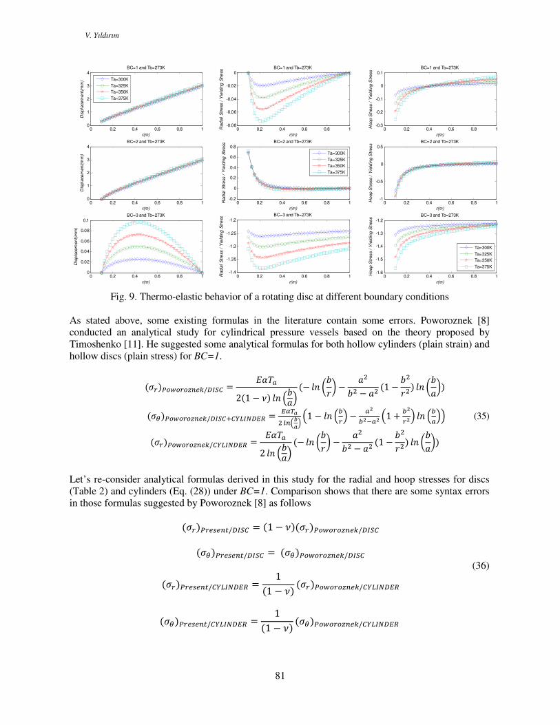
To gain insight into the issue in question, an additional numerical example is performed for both the
discs and cylindrical vessels having the same inner and outer radii (a=0.5m, b=1m) for BC=1. The
results are shown in Fig. 10 in a comparative manner by using the same axis-scales. From the overall
picture the characteristics of the curves are similar to each other. However numerical values of the
quantities are not the same. For example, the same temperature difference results in higher stresses in
cylinders than discs.
Finally, it is possible to obtain plane-stress formulas from the plane strain formulas by using
appropriate coefficients. The converse is also true. In the elementary elasticity theory those coefficients
are given for mechanical loads such as rotation and internal/external pressures. For instance, if one
replace formally G with 424, and E with
24) he may get the results for the plain-strain case from the
plane stress solutions. As it is known G should be replaced formally with 4234, and E is to be replaced
with (23&4)(234)) to get the plane stress results from the plain strain solutions. However this does not work
alone for thermo-elastic analysis.
V. Yıldırım
84
Fig. 10. Comparison of results for discs and cylinders (a=0.5m, b=1m) under BC=1
V. Yıldırım
85
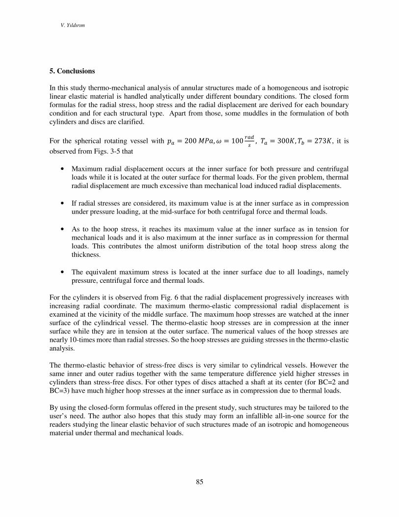
5. Conclusions
In this study thermo-mechanical analysis of annular structures made of a homogeneous and isotropic
linear elastic material is handled analytically under different boundary conditions. The closed form
formulas for the radial stress, hoop stress and the radial displacement are derived for each boundary
condition and for each structural type. Apart from those, some muddles in the formulation of both
cylinders and discs are clarified.
For the spherical rotating vessel with 9 = 200 8, 5 = 100 T , 1 = 300F, 1; = 273F, it is
observed from Figs. 3-5 that
• Maximum radial displacement occurs at the inner surface for both pressure and centrifugal loads while it is located at the outer surface for thermal loads. For the given problem, thermal
radial displacement are much excessive than mechanical load induced radial displacements.
• If radial stresses are considered, its maximum value is at the inner surface as in compression under pressure loading, at the mid-surface for both centrifugal force and thermal loads.
• As to the hoop stress, it reaches its maximum value at the inner surface as in tension for
mechanical loads and it is also maximum at the inner surface as in compression for thermal
loads. This contributes the almost uniform distribution of the total hoop stress along the
thickness.
• The equivalent maximum stress is located at the inner surface due to all loadings, namely
pressure, centrifugal force and thermal loads.
For the cylinders it is observed from Fig. 6 that the radial displacement progressively increases with
increasing radial coordinate. The maximum thermo-elastic compressional radial displacement is
examined at the vicinity of the middle surface. The maximum hoop stresses are watched at the inner
surface of the cylindrical vessel. The thermo-elastic hoop stresses are in compression at the inner
surface while they are in tension at the outer surface. The numerical values of the hoop stresses are
nearly 10-times more than radial stresses. So the hoop stresses are guiding stresses in the thermo-elastic
analysis.
The thermo-elastic behavior of stress-free discs is very similar to cylindrical vessels. However the
same inner and outer radius together with the same temperature difference yield higher stresses in
cylinders than stress-free discs. For other types of discs attached a shaft at its center (for BC=2 and
BC=3) have much higher hoop stresses at the inner surface as in compression due to thermal loads.
By using the closed-form formulas offered in the present study, such structures may be tailored to the
user’s need. The author also hopes that this study may form an infallible all-in-one source for the
readers studying the linear elastic behavior of such structures made of an isotropic and homogeneous
material under thermal and mechanical loads.

V. Yıldırım
86
APPENDIX: Displacement and stresses of uniform isotropic and homogeneous discs
subjected to mechanical loads [10] (9 = XX" 9"!", 9; = !" 9"!")
(8) = −9 (:) = −9;
!= − 8&9(:&(G + 1) − (G − 1)"&)K"(8& − :&) + :&9;(8&(G + 1) − (G − 1)"&)K"(8& − :&)
= 8&9(:& − "&)"&(8& − :&) + :&9;(8 − ")(8 + ")"&(:& − 8&) = − 8&9(:& + "&)"&(8& − :&) + :&9;(8& + "&)"&(8& − :&)
(8) = 0 (:) = 0
! = j5&(8&(G + 3)(:&(G + 1) − (G − 1)"&) − (G − 1)"&(:&(G + 3) − (G + 1)"&))8K"
= j5&(G + 3)(8& − "&)("& − :&)8"& = j5&(8&(G + 3)(:& + "&) + "&(:&(G + 3) − (3G + 1)"&))8"&
!(8) = 0 (:) = 0
!=5&jI8&(G + 3)(:&(G + 1) − (G − 1)"&) − (G − 1)"&(:&(G + 3) − (G + 1)"&)J8"K
=(G + 3)5&(8 − ")(8 + ")("& − :&)j8"&
= 5&jI8&(G + 3)(:& + "&) + "&(:&(G + 3) − (3G + 1)"&)J8"&
!(8) = 0 !(:) = 0
!= (G& − 1)5&("& − 8&)("& − :&)j8"K
= 5&j \8&I(G + 1)"& − :&(G − 1)J + "&(:&(G + 1) − (G + 3)"&)]8"&
= 5&jI8&(:&(G − 1) + (G + 1)"&) + "&(:&(G + 1) − (3G + 1)"&)J8"&

V. Yıldırım
87
Notations
a, b Inner radius and outer radius, respectively
21 , CC Integration constants
ijC elastic constants in Hooke’s law
E Young’s modulus 9, 9; Pressures at inner and outer surfaces, respectively
r radial coordinate
aT , bT temperature at the inner and outer surfaces, respectively
ru radial displacement
rε radial strain
θε
tangential strain
α thermal expansion coefficient
θφφθ γγγ rr ,,
engineering shear strain components ∅ Azimuthal coordinate
ν Poisson’s ratio j density of the vessel material
rσ radial stress
θσ hoop stress $ tangential coordinate 5 constant angular velocity (rad/s)
References
[1] Bower, A. F., Applied Mechanics of Solids; Taylor and Francis, 2012.
[2] Young, W.C., Budynas, R.G., Roark’s Formulas for Stress and Strain; McGraw-
Hill, Seventh Edition, New York. 2002.
[3] Hetnarski, B., Eslami, M.R., Thermal Stresses-Advanced Theory and Applications;
Springer, 2009.
[4] Nayak, P., Mondal, S.C., Nandi, A., Stress, strain and displacement of a functionally
graded thick spherical vessel. International Journal of Engineering Science and
Technology (IJEST), 3/4, 2659-2671, 2011.
[5] Chakrabarty, J., Theory of Plasticity; McGraw Hill, New York, 1998.
[6] Noda, N., Hetnarski, R.B., Tanigawa , Y., Thermal Stresses; Taylor and Francis,
New York, 2003.
[7] Heat Transfer Problems and Thermal Stresses, FEM II. Comp. Lab,
www.meil.pw.edu.pl/sms/content/download/24488/.../FEMII_LAB_THERM_v2.pdf
[8] Poworoznek, P.P., Elastic-Plastic Behavior of a Cylinder Subject to Mechanical and
Thermal Loads; Rensselaer Polytechnic Institute, Master Thesis, Hartford, CT.
2008.
[9] Kanlıkama, B., Abuşoğlu, A., Güzelbey, İ.H. Coupled thermoelastic analysis of
thick-walled pressurized cylinders. International Journal of Energy and Power
Engineering, 2/2, 60-68. 2013.
[10] Yıldırım, V., Analytic solutions to power-law graded hyperbolic rotating discs
subjected to different boundary conditions. International Journal of Engineering &
Applied Sciences (IJEAS), 8/1, 38-52, 2016.
[11] Timoshenko, S., Strength of Material Part II, Advanced Theory and Problems, 3rd
Edition, D. Van Nostrand Company Inc., Princeton, NJ, 1956.