Heat Generation and Transport
29
Transcript of Heat Generation and Transport

Session 4: Heat Generation and
Transport
• Why do we consider Thermal Hydraulics on nuclear reactor ?
– For a reactor to operate in steady state, heat generated by nuclear
reaction must be removed as fast as it is produced.
• The balance is accomplished by coolant system.
• Major objectives in the design of a reactor coolant system
– To provide for the removal of the heat produced at the desired power
level while ensuring that the maximum fuel temperature is always below
this predetermined value.
– The predetermined value is
• To prevent the fuel melting
– Control LPD (local power density)
• To maintain the integrity of cladding
– Control heat flux ( DNBR, Departure from Nucleate Boiling Ratio)
Heat Generation and Transport
• In this session, we will discuss the followings:
– General thermodynamic considerations
– Heat transfer from fuel to coolant
– Critical heat flux and DNBR
– Thermal design of a Reactor

The 1st Law of Thermodynamics
• The first law of thermodynamics can be stated in the law of conservation of energy.
– This states that energy can be neither created nor destroyed. However, energy can change forms and energy can flow from one place to another. The total energy of an isolated system remains the same.
– The change in internal energy of a system is equal to the heat added to the system minus the work done by the system.
ΔU = Q - W – An isobaric process is a constant pressure process. ΔU, W, and
Q are generally non-zero, but calculating the work done by an ideal gas is straightforward. Water boiling in a saucepan is an example of an isobar process
W = P·ΔV
ΔU+ P·ΔV= Q
Δh= Q , we can rewrite Δh to the temperature form as CPΔT.

Thermodynamic Point of View on
Coolant System
• Nuclear reactor is a device in which energy is produced and
transferred to a moving fluid such as water, liquid metal, and gas.
• We know the reactor power and cycle efficiency using the
thermodynamic law.
• 1st Law of thermodynamics : energy conservation law
– Energy generation is equal to the net flow of energy (Steady state)
Egeneration Ein Eout Eg= Eout- Ein
Thermodynamic Point of View on
Coolant System
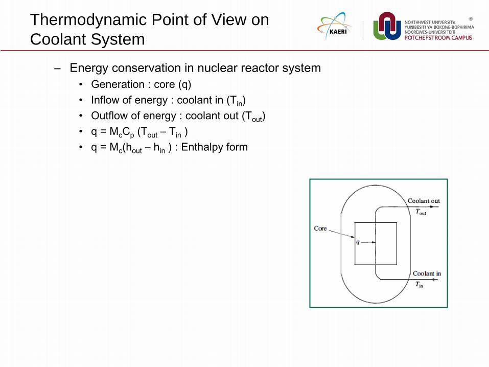
– Energy conservation in nuclear reactor system
• Generation : core (q)
• Inflow of energy : coolant in (Tin)
• Outflow of energy : coolant out (Tout)
• q = McCp (Tout – Tin )
• q = Mc(hout – hin ) : Enthalpy form

Enthalpy Formulation of Energy
Conservation (1)
• Situation of phase change in nuclear reactor system
– We suppose the BWR situation considering phase change, that means the
vaporization of water as shown in Figure.
– In this reactor, a portion of the water passing through the core is
vaporized to steam, exits from the reactor via a steam pipe to the turbine,
and returns as feed water from the condenser.
– The water is first heated from the point its entering temperature Tin.
to the temperature at which it boils,
that is, saturation temperature, Tsat.
– The water temperature does not rise
above this value.
– The associated increase in enthalpy is
sat
in
T
f in PT
h h C T dT

Enthalpy Formulation of Energy
Conservation (2)
• Situation of phase change in nuclear reactor system
– With the onset of boiling, the water absorbs an amount of heat equal to
the heat of vaporization, denoted by hfg
– The specific enthalpy of the steam is
– Heat balance with phase change (No explicit change)
• q = Mc(hout – hin )
– For example, BWR operating at a 6.9 MPa produces 814.8 kg/s of
steam. Feed water enters the reactor at 214 C.
At what power is the reactor operating?
• According to steam table, at a pressure of 6.9MPa,
saturation temperature is 320.5 C
• According to steam table, enthalpy at subcooled of 214C
and saturation of 6.9MPa is 810 and 2774 kJ/kg, respectively.
• q = 814.8 kg/s x (2774-810)kJ/kg = 1600 MW
sat
in
T
out f fg in P fgT
h h h h C T dT h
Heat Transfer from Fuel to Coolant
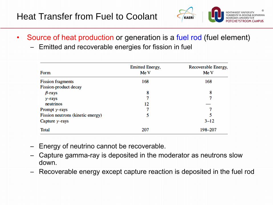
• Source of heat production or generation is a fuel rod (fuel element)
– Emitted and recoverable energies for fission in fuel
– Energy of neutrino cannot be recoverable.
– Capture gamma-ray is deposited in the moderator as neutrons slow down.
– Recoverable energy except capture reaction is deposited in the fuel rod

Heat Transfer from Rod to Coolant (1)
• Energy is removed from a reactor by two fundamentally different
heat transfer process, conduction and convection.
– In conduction, heat is transmitted from one location in a body to another
as a result of a temperature difference existing in the body.
• By this mechanism, Heat produced in a fuel rod is transferred to the surface
of the rod.
– In convection, it is the transfer of heat to a moving liquid or gas.
• The heat conducted to the surface of a fuel rod is carried into the coolant
and out of the system by convection

Fuel centerline
Fuel Gap Cladding
Coolant
Cladding
Coolant enthalpy at top
Coolant enthalpy at bottom
Heat flux Heat flux
Power
generation
Heat Transfer from Rod to Coolant (2)
• Conduction in fuel rod is
– To derive Temperature distribution
– To estimate Centerline temperature
– To calculate Power generation
• Heat transfer of Gap b/w fuel and cladding is
– To be govern by Gap heat transfer
– To derive effective heat transfer coefficient
• Conduction in cladding is
– To derive Temperature distribution
– To estimate Surface temperature
– To calculate Wall temperature
• Convective heat transfer in coolant is
– To derive Enthalpy rise
– To estimate Convective heat transfer coefficient
– To calculate Coolant condition of hot channel

Conduction in Fuel Rod (1)
• Energy is removed from a reactor by two fundamental process –
conduction and convection
• The equation of heat conduction
– The fundamental law : Fourier’s law
– Energy conservation :
• Heat flow :
• Heat production:
• Energy conservation :
" '''q q
Applying Fourier’s law
( ) '''k T q

Conduction in Fuel Rod (2)
• Heat conduction for fuel rod
– Considering a long cylindrical fuel rod of radius ‘a’ surrounded by
cladding of thickness ‘b’.
– Heat is produced at the constant rate q’’’.
– Governing equation and BC
• BC
• General Solution
• Applying BC and temperature distribution in the rod is:
• Power is induced by neutron flux and fission cross section:
Fuel centerline
Fuel Cladding
a b
Tm r Ts Tc

Conduction in Fuel Rod (3)
• Heat conduction for the cladding
– Governing equation and BC
• BC :
• General solution :
• Applying BC and temperature distribution in the rod is :
Fuel centerline
Fuel Cladding
a b
Tm r Ts Tc

Convection to Coolant (1)
• Heat transfer to coolant
– The fundamental relation describing the transfer of heat from a solid to a
moving fluid is Newton’s cooling law
– Typical values of the convective heat transfer coefficient is following as :
Ref by Fundamentals of heat and
mass transfer by F. P. Incropera

Convection to Coolant (2)
– Since the temperature of the coolant varies with location across each channel, it is necessary to integrate the local temperature
• Mixed mean or bulk temperature of the fluid is defined by the flow velocity weighting over the cross section of the channel.
– Heat transfer coefficient is defined by following nondimensional number
• Flow characteristics is characterized by
Reynolds number
• Thermal diffusion characteristics is characterized
by Prandtl number
• Geometry characteristics : Equivalent diameter
• Convection characteristics : Nusselt number

Convection to Coolant (3)
• Convective heat transfer is calculated by the following correlation:
– In Laminar flow (uniform heat flux), that is low region less than 3000 of
Reynolds number
•
– Turbulent flow (ReD > 10,000)
• Dittus-Boelter correlation (Pipe flow) is the most famous correlation.
• Weisman correlation (Square rod array) is widely used in the field of nuclear
industry
Analysis of Reactor Heat Transfer (1)
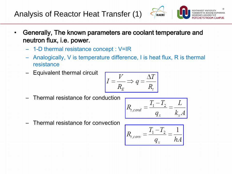
• Generally, The known parameters are coolant temperature and
neutron flux, i.e. power.
– 1-D thermal resistance concept : V=IR
– Analogically, V is temperature difference, I is heat flux, R is thermal
resistance
– Equivalent thermal circuit
– Thermal resistance for conduction
– Thermal resistance for convection

Analysis of Reactor Heat Transfer (2)
• Thermal resistance equation of nuclear fuel rod
– Thermal circuit
– Thermal resistance equation
Tm
Ts Tc Tb Rf Rc Rb
Rod Cladding Coolant
Temperature
Difference
Heat flow
Thermal
resistance
m sT T s cT T c bT T
q q q
1
4 fHk
ln 1 /
2 c
b a
Hk
1
2 ( )h a b H
Fuel centerline
Fuel Cladding
a b
Tm r Ts Tc
Cladding
Coolant
Tb kf kc h

Boiling Flow Phenomena (1)
• As indicated in the figure, the heat flux increases slowly as the rod temperature is increased at low values.
• Region 1(Natural convection) : Heat is transferred to the coolant by ordinary convection with no phase change.
• Region 2 (Partial nucleate boiling) : Vapor bubbles begin to form at various imperfections on the surface of the fuel rods. It is a form of boiling called nucleate boiling. The bulk temperature is less than its saturation.
The vapor in the bubbles soon condenses to
liquid state. There is no net production of steam
under these circumstances and the boiling process is termed subcooled nucleate boiling
• Region 3(Transition at B) :When the bulk temperature of the coolant reaches its saturation, the bubbles persist within the coolant stream, there begins to be a net output of stream, and the system is termed saturated nucleate boiling or bulk boiling

Boiling Flow Phenomena (2)
• Point C (Critical Heat Flux, Boiling Crisis, Burnout, Departure from Nucleate Boiling) : When the temperature of the surface of the fuel is increase in the nucleate boiling region, the density of bubbles at or near the surface of the fuel rods also increases. Eventually, a point is reached where the bubble density becomes so great that adjacent bubbles coalesce and begin to form a vapor film across the surface of the rods. This point is termed CHF, DNB, Burnout, Boiling Crisis.
• Region 4 (Partial film boiling) : With the onset of CHF, the heat transfer begins to drop. In this region, vapor covered the whole rod surface. The heat is only transferred to the coolant through the vapor by conduction and radiation. The heat flux continues to drop, with increasing fuel temperatures as the total area of the film covering the fuel increases.
It is termed partial film boiling
• Region 5(Full film boiling) : Beyond this region, any increase in temperature leads to an increase in the heat flux, because heat transfer through the film increases with the temperature difference across the film, though a poor and inefficient process.
It is termed full film boiling

Video Gallery of Boiling Flow Phenomena
• The videos show the pool boiling process on a flat, circular heated
plate. The tests were carried out with saturated isopropanol at a 1
atm and a saturation temperature of 83.3 C under steady state
condition.
• Boiling regime
– A-video : low heat flux nucleate
boiling
– B-video : developed nucleate
boiling at higher heat flux
– C-video : DNB
– D-video : transition boiling
– E-video : film boiling
A
B C
D
E

Critical Heat Flux (1)
• Definition of CHF
– Critical Heat Flux (CHF) is the fuel cladding surface
heat flux at which either DNB (Departure from
Nucleate Boiling) or LFD (Liquid Film Dryout)
occurs.
– LFD type(BWR) : CHF occurs when the flow rate of
the liquid film on the heated surface falls to zero,
which can be modeled by considering evaporation,
entrainment and deposition.
• Consequence of CHF
– To lead the rapid increase of clad temperature
– To result in the cladding failure, eventually.
Video-CHF from MIT

Critical Heat Flux (2)
• DNB type (PWR) :
– Plausible Three DNB Mechanisms
• DNB type critical heat flux occurred when a Bubble crowding and vapor blanketing near the wall isolated the liquid on the rod wall surface.
• Vapor injection into the liquid stream reduced the liquid velocity gradient near the wall. The liquid separate from the wall, resulting in a transition from nucleate to film boiling when the rate of vapor effusion increases beyond a critical level
• A bubble boundary layer builds up on the surface and vapor generated by boiling at the wall surface must escape through this boundary layer. When the boundary layer becomes too crowded with bubble, outward vapor flow away from the wall is impossible. The surface becomes dry and overheats which leads to burnout.
Video-CHF

Design Criteria and SAFDL
• Design Criteria
– 10CFR50 App. A - General Design Criterion 10: The reactor core and associated
coolant, control and protection systems shall be designed with appropriate margin to
assure that SAFDL (Specified Acceptable Fuel Design Limits) are not exceeded
during any condition of normal operation, including the effect of AOO(Anticipated
Operating Occurrence).
• SAFDL (Specified Acceptable Fuel Design Limits)
– Cladding overheating due to DNB (Departure from nucleate boiling) / LFD (Liquid film
dryout) or hydrodynamic flow instability
– Fuel melting or material phase change
• Melting Linear Power Generation : 25kW/ft
• Melting temp: 2760 ~2815 oC)
OPR-1000 SMART RR
DNBR > 1.3 > 1.5 > 2.1
LPD < 21kW/ft < 17.87kW/ft < 26.33kW/ft
Pressure < 18.96 MPa < 18.7MPa < 110% (closed type)
PCT(LOCA) <1204℃(2200℉) <1204℃(2200℉) < 570 ℃
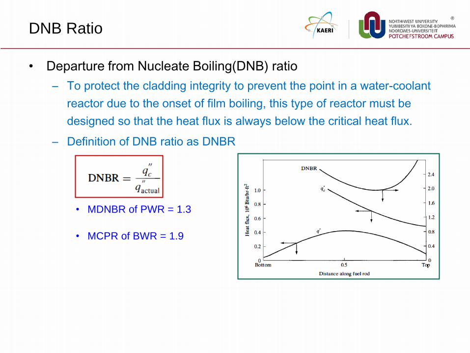
DNB Ratio
• Departure from Nucleate Boiling(DNB) ratio
– To protect the cladding integrity to prevent the point in a water-coolant
reactor due to the onset of film boiling, this type of reactor must be
designed so that the heat flux is always below the critical heat flux.
– Definition of DNB ratio as DNBR
• MDNBR of PWR = 1.3
• MCPR of BWR = 1.9
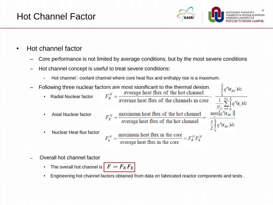
Hot Channel Factor
• Hot channel factor
– Core performance is not limited by average conditions, but by the most severe conditions
– Hot channel concept is useful to treat severe conditions:
• Hot channel : coolant channel where core heat flux and enthalpy rise is a maximum.
– Following three nuclear factors are most significant to the thermal design.
• Radial Nuclear factor
• Axial Nuclear factor
• Nuclear Heat flux factor
– Overall hot channel factor
• The overall hot channel is
• Engineering hot channel factors obtained from data on fabricated reactor components and tests .

Reactor Design
• Reactor Design in aspect of DNBR
– “The art of compromise” : In designing a reactor, there is considerable overlap between those aspects of the problem that are specifically nuclear, thermal-hydraulics, fuel design, radiation shielding.
– In water-cooled reactor, DNBR ratio is a crucial design parameter as a function of distance along the hot channel.
– Local heat flux in hot channel is evaluated using the hot channel factor as:
– DNBR is calculated with respect to the local heat flux in hot channel, q’’max .
– If the computed DNBR is not satisfied with the preset design limit DNBR, the parameters of the lattice or the coolant flow are changed, and a ne DNBR is obtained.
– The computation process are repeated until the desired limit DNBR.

Thank you