Heat Dissipation from Stationary Passenger Car Brake Discs
14
*Corr. Author’s Address: University of Belgrade, Faculty of Mechanical Engineering, Kraljice Marije 16, Belgrade, Serbia, [email protected] 15 Strojniški vestnik - Journal of Mechanical Engineering 66(2020)1, 15-28 Received for review: 2019-01-15 © 2020 Journal of Mechanical Engineering. All rights reserved. Received revised form: 2019-05-07 DOI:10.5545/sv-jme.2019.6002 Original Scientific Paper Accepted for publication: 2019-07-11 Heat Dissipation from Stationary Passenger Car Brake Discs Topouris, S. – Stamenković, D. – Olphe-Galliard, M. – Popović, V. – Tirovic, M. Stergios Topouris 1 – Dragan Stamenković 2,* – Michel Olphe-Galliard 1 – Vladimir Popović 2 - Marko Tirovic 1 1 Cranfield University, School of Aerospace, Transport and Manufacturing, United Kingdom 2 University of Belgrade, Faculty of Mechanical Engineering, Serbia This paper presents an experimental investigation of the heat dissipation from stationary brake discs concentrated on four disc designs: a ventilated disc with radial vanes, two types of ventilated discs with curved vanes (a non-drilled and cross-drilled disc), and a solid disc. The experiments were conducted on a purpose-built thermal spin rig and provided repeatable and accurate temperature measurement and reliable prediction of the total, convective and radiative heat dissipation coefficients. The values obtained compare favourably with computational fluid dynamics results for the ventilated disc with radial vanes and solid disc, though the differences were somewhat pronounced for the ventilated disc. The speeds of the hot air rising above the disc are under 1 m/s, hence too low to experimentally validate. However, the use of a smoke generator and suitable probe was beneficial in qualitatively validating the flow patterns for all four disc designs. Convective heat transfer coefficients increase with temperature, but the values are very low, typically between 3 W/(m 2 K) and 5 W/(m 2 K) for the disc designs and temperature range analysed. As expected, from the four designs studied, the disc with radial vanes has the highest convective heat dissipation coefficient and the solid disc the lowest, being about 30 % inferior. Convective heat dissipation coefficient for the discs with curved vanes was about 20 % lower than for the disc with radial vanes, with the cross-drilled design showing marginal improvement at higher temperatures. Keywords: brake disc, heat dissipation, convective cooling, computational fluid dynamics, natural convection Highlights • Heat dissipation from stationary brake discs was investigated. • It was done via a thermal spin rig test, computational fluid dynamics analysis, and a smoke generator test. • Radial vanes provide the highest convective heat dissipation coefficient and solid disc the lowest, with curved vanes being in the middle. • The cross-drilled design shows only marginal improvement. 0 BACKGROUND Brake cooling is vital for safe vehicle operation and has attracted substantial research from very early days; however, most research and published data relate to heat dissipation from rotating discs. Cooling of a stationary brake is equally important as many critical cases are related to this driving condition. For instance, brake fluid is much more likely to boil if the vehicle is not moving. The consequences can only become apparent once the vehicle starts moving again, making the situation safety-critical. Convective heat dissipation is drastically reduced, from predominantly forced cooling (at high airspeeds) to natural convection only (airspeed being zero). Instead of the heat being dissipated to the surrounding air, which is propelled away from the brake, much more heat is being transmitted to pads and calliper through conduction and radiation. Furthermore, a considerable portion of the heat being dissipated from the disc by natural convection is heating the calliper as the hot air is forced upwards by the natural convection. The air surrounding the brake assembly is “trapped” within the wheel and wheel arch cavities, and the brake ambient temperature is rapidly increasing, well above the outside ambient air temperature. The situation might be equally critical during “hot parking” when the vehicle is parked after heavy brake use. In such conditions, some brake components can reach higher temperatures than for a moving vehicle. Traditionally, the risks with “hot parking” were related to the boiling of brake fluid, but vehicle “rollaway” is another potentially critical condition. As the disc and pads cool down they “shrink” (their thickness reduces) whereas the calliper expands as it heats up as a result of a heat transferred from the pads and disc. This leads to the reduction of the clamp force, causing decrease in friction force (braking torque) and potentially leading to rollaway if the vehicle is parked on a gradient. The condition is most critical when installing an electric parking brake (EPB) for which long flexible cables are not used, and there is no flexibility in the system to compensate for reduction in disc and pad thickness. EPB has brought hot parking to an entirely new level, ensuring safe vehicle parking on a gradient (specified at 20 % by UN Regulation No. 13-H [1]). The methodologies used to cope with this challenge include “over-clamping” (i.e., applying much higher force than required in order to “stretch” the calliper, which should compensate for disc and pad shrinkage) and re-parking (i.e., re-applying the brake automatically after the vehicle has been parked).
Transcript of Heat Dissipation from Stationary Passenger Car Brake Discs

*Corr. Author’s Address: University of Belgrade, Faculty of Mechanical Engineering, Kraljice Marije 16, Belgrade, Serbia, [email protected] 15
Strojniški vestnik - Journal of Mechanical Engineering 66(2020)1, 15-28 Received for review: 2019-01-15© 2020 Journal of Mechanical Engineering. All rights reserved. Received revised form: 2019-05-07DOI:10.5545/sv-jme.2019.6002 Original Scientific Paper Accepted for publication: 2019-07-11
Heat Dissipation from Stationary Passenger Car Brake DiscsTopouris, S. – Stamenković, D. – Olphe-Galliard, M. – Popović, V. – Tirovic, M.
Stergios Topouris1 – Dragan Stamenković2,* – Michel Olphe-Galliard1 – Vladimir Popović2 - Marko Tirovic1
1 Cranfield University, School of Aerospace, Transport and Manufacturing, United Kingdom 2 University of Belgrade, Faculty of Mechanical Engineering, Serbia
This paper presents an experimental investigation of the heat dissipation from stationary brake discs concentrated on four disc designs: a ventilated disc with radial vanes, two types of ventilated discs with curved vanes (a non-drilled and cross-drilled disc), and a solid disc. The experiments were conducted on a purpose-built thermal spin rig and provided repeatable and accurate temperature measurement and reliable prediction of the total, convective and radiative heat dissipation coefficients. The values obtained compare favourably with computational fluid dynamics results for the ventilated disc with radial vanes and solid disc, though the differences were somewhat pronounced for the ventilated disc. The speeds of the hot air rising above the disc are under 1 m/s, hence too low to experimentally validate. However, the use of a smoke generator and suitable probe was beneficial in qualitatively validating the flow patterns for all four disc designs. Convective heat transfer coefficients increase with temperature, but the values are very low, typically between 3 W/(m2K) and 5 W/(m2K) for the disc designs and temperature range analysed. As expected, from the four designs studied, the disc with radial vanes has the highest convective heat dissipation coefficient and the solid disc the lowest, being about 30 % inferior. Convective heat dissipation coefficient for the discs with curved vanes was about 20 % lower than for the disc with radial vanes, with the cross-drilled design showing marginal improvement at higher temperatures.Keywords: brake disc, heat dissipation, convective cooling, computational fluid dynamics, natural convection
Highlights• Heat dissipation from stationary brake discs was investigated.• It was done via a thermal spin rig test, computational fluid dynamics analysis, and a smoke generator test.• Radial vanes provide the highest convective heat dissipation coefficient and solid disc the lowest, with curved vanes being in
the middle.• The cross-drilled design shows only marginal improvement.
0 BACKGROUND
Brake cooling is vital for safe vehicle operation and has attracted substantial research from very early days; however, most research and published data relate to heat dissipation from rotating discs. Cooling of a stationary brake is equally important as many critical cases are related to this driving condition. For instance, brake fluid is much more likely to boil if the vehicle is not moving. The consequences can only become apparent once the vehicle starts moving again, making the situation safety-critical. Convective heat dissipation is drastically reduced, from predominantly forced cooling (at high airspeeds) to natural convection only (airspeed being zero). Instead of the heat being dissipated to the surrounding air, which is propelled away from the brake, much more heat is being transmitted to pads and calliper through conduction and radiation. Furthermore, a considerable portion of the heat being dissipated from the disc by natural convection is heating the calliper as the hot air is forced upwards by the natural convection. The air surrounding the brake assembly is “trapped” within the wheel and wheel arch cavities, and the brake ambient temperature is rapidly increasing, well above the outside ambient air temperature.
The situation might be equally critical during “hot parking” when the vehicle is parked after heavy brake use. In such conditions, some brake components can reach higher temperatures than for a moving vehicle. Traditionally, the risks with “hot parking” were related to the boiling of brake fluid, but vehicle “rollaway” is another potentially critical condition. As the disc and pads cool down they “shrink” (their thickness reduces) whereas the calliper expands as it heats up as a result of a heat transferred from the pads and disc. This leads to the reduction of the clamp force, causing decrease in friction force (braking torque) and potentially leading to rollaway if the vehicle is parked on a gradient. The condition is most critical when installing an electric parking brake (EPB) for which long flexible cables are not used, and there is no flexibility in the system to compensate for reduction in disc and pad thickness. EPB has brought hot parking to an entirely new level, ensuring safe vehicle parking on a gradient (specified at 20 % by UN Regulation No. 13-H [1]). The methodologies used to cope with this challenge include “over-clamping” (i.e., applying much higher force than required in order to “stretch” the calliper, which should compensate for disc and pad shrinkage) and re-parking (i.e., re-applying the brake automatically after the vehicle has been parked).

Strojniški vestnik - Journal of Mechanical Engineering 66(2020)1, 15-28
16 Topouris, S. – Stamenković, D. – Olphe-Galliard, M. – Popović, V. – Tirovic, M.
With the installation of electric and electronic components into callipers (EPB, “low drag” callipers, etc.), there is a potential danger with overheating and permanent damage to these parts; hence, accurate prediction of brake temperatures in parking conditions is becoming even more critical.
Heat dissipation from stationary brake is also vital for accurately predicting brake temperatures in drive cycles which contain periods when the vehicle is stationary. Though these cycles are typically not safety-critical from the brake performance point of view, brake temperatures are essential in understanding and minimizing residual drag, providing good brake pedal feel and reliably estimating brake wear.
Finally, braking of hybrid and electric vehicles (HEVs) imposes another braking challenge, in addition to complexities related to brake pedal feel, residual drag, and EPB. UN Regulation No. 13-H requires all braking tests (such as repeated brake applications – “fade and recovery”) to be successfully performed by friction brakes only, without the use of regenerative braking. Considering that HEVs are typically heavier than equivalent cars with internal combustion engines only, understanding braking requirements is paramount not only regarding safety but also in order to minimize brake mass and resolve brake cooling in the most effective way for both moving and stationary vehicle operation. Though some of these vehicles are relatively low performance, there are some extremely high-performance HEVs with very rapid acceleration characteristics and therefore very high braking demands.
When analysing brake thermal aspects in parking conditions, it should be pointed out that critical cooling times can be quite prolonged; for passenger cars with conventional hand brake designs, rollaways are known to have occurred up to 30 minutes after the vehicle was parked with hot brakes. This was for “medium gradients” (~10 %); as for the higher gradients, the rollaway occurs much quicker. In commercial vehicles, the critical period can be up to 1 hour [2].
As a first step in studying heat dissipation from stationary passenger car disc brake assemblies, the focus will be on the brake disc. Four types of brake discs will be studied, for two passenger vehicles. The first vehicle is Volkswagen Passat (Typ 3C) and the second Lotus Elise S2, with the basic vehicle and disc characteristics given in Table 1.
Brake discs are shown in Fig. 1, with Figs 1a and b presenting VW Passat front and rear discs, respectively. Lotus Elise S2 standard disc is marked Fig. 1c, with Fig 1d presenting a cross-drilled disc
(the perspective of the photo can confuse the reader leading to the perception that Lotus discs are unequal in diameter). From Fig. 1 it can be noted that all three ventilated discs are of a “swan neck” type, meaning that the outboard disc friction face is attached to the top hat section but using a “swan neck” type feature in order to minimize disc coning. This design allows air intake from the inboard side, resulting in good cooling characteristics.
Table 1. Vehicle characteristics
CharacteristicsVW Passat 2.0T
FSI 2007Lotus Elise S2
2011Gross vehicle mass [kg] 2100 1141Static front axle load [kg] 1080 570.5Static rear axle load [kg] 1020 570.5Wheelbase [mm] 2709 2300Maximum engine power [kW] 147 89*Maximum vehicle speed [km/h] 235 205
Front disc typeVentilated with radial vanes
Ventilated with curved vanes**
Front disc outer diameter [mm] 321 288***
Rear disc type SolidVentilated with
curved vanes**Rear disc outer diameter [mm] 286 288***
* Basic model** Option: Cross-drilled*** Front and rear discs are identical
Fig. 1. Discs Analysed - VW Passat: a) front, b) rear Lotus Elise S2: c) standard, d) cross-drilled
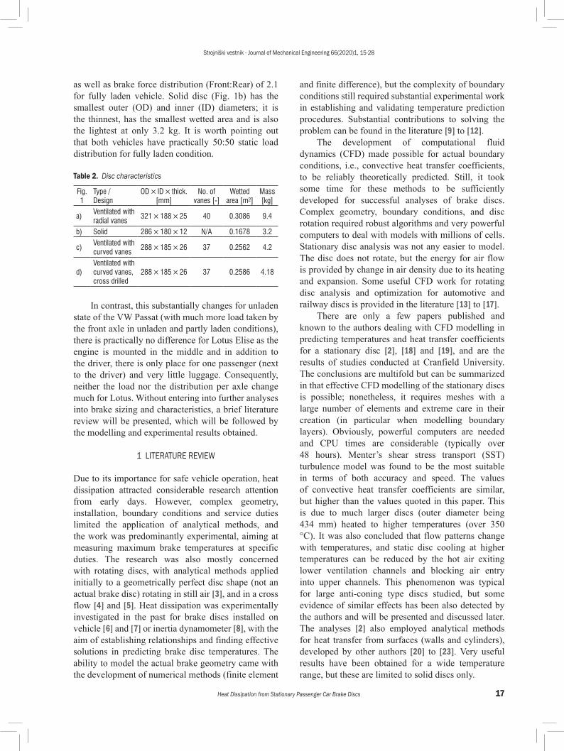
Detailed design characteristics for all four discs studied are presented in Table 2. At the beginning of the research, all discs were brand new. To stabilize emissivity values they were repeatedly heated and cooled, which caused all surfaces to corrode. The front VW Passat disc (Fig 1a) is the largest and heaviest, owing to the high vehicle mass and maximum speed,
Strojniški vestnik - Journal of Mechanical Engineering 66(2020)1, 15-28
17Heat Dissipation from Stationary Passenger Car Brake Discs
as well as brake force distribution (Front:Rear) of 2.1 for fully laden vehicle. Solid disc (Fig. 1b) has the smallest outer (OD) and inner (ID) diameters; it is the thinnest, has the smallest wetted area and is also the lightest at only 3.2 kg. It is worth pointing out that both vehicles have practically 50:50 static load distribution for fully laden condition.
Table 2. Disc characteristics
Fig. 1
Type / Design
OD × ID × thick. [mm]
No. of vanes [-]
Wetted area [m2]
Mass [kg]
a)Ventilated with radial vanes
321 × 188 × 25 40 0.3086 9.4
b) Solid 286 × 180 × 12 N/A 0.1678 3.2
c)Ventilated with curved vanes
288 × 185 × 26 37 0.2562 4.2
d)Ventilated with curved vanes, cross drilled
288 × 185 × 26 37 0.2586 4.18
In contrast, this substantially changes for unladen state of the VW Passat (with much more load taken by the front axle in unladen and partly laden conditions), there is practically no difference for Lotus Elise as the engine is mounted in the middle and in addition to the driver, there is only place for one passenger (next to the driver) and very little luggage. Consequently, neither the load nor the distribution per axle change much for Lotus. Without entering into further analyses into brake sizing and characteristics, a brief literature review will be presented, which will be followed by the modelling and experimental results obtained.
1 LITERATURE REVIEW
Due to its importance for safe vehicle operation, heat dissipation attracted considerable research attention from early days. However, complex geometry, installation, boundary conditions and service duties limited the application of analytical methods, and the work was predominantly experimental, aiming at measuring maximum brake temperatures at specific duties. The research was also mostly concerned with rotating discs, with analytical methods applied initially to a geometrically perfect disc shape (not an actual brake disc) rotating in still air [3], and in a cross flow [4] and [5]. Heat dissipation was experimentally investigated in the past for brake discs installed on vehicle [6] and [7] or inertia dynamometer [8], with the aim of establishing relationships and finding effective solutions in predicting brake disc temperatures. The ability to model the actual brake geometry came with the development of numerical methods (finite element
and finite difference), but the complexity of boundary conditions still required substantial experimental work in establishing and validating temperature prediction procedures. Substantial contributions to solving the problem can be found in the literature [9] to [12].
The development of computational fluid dynamics (CFD) made possible for actual boundary conditions, i.e., convective heat transfer coefficients, to be reliably theoretically predicted. Still, it took some time for these methods to be sufficiently developed for successful analyses of brake discs. Complex geometry, boundary conditions, and disc rotation required robust algorithms and very powerful computers to deal with models with millions of cells. Stationary disc analysis was not any easier to model. The disc does not rotate, but the energy for air flow is provided by change in air density due to its heating and expansion. Some useful CFD work for rotating disc analysis and optimization for automotive and railway discs is provided in the literature [13] to [17].
There are only a few papers published and known to the authors dealing with CFD modelling in predicting temperatures and heat transfer coefficients for a stationary disc [2], [18] and [19], and are the results of studies conducted at Cranfield University. The conclusions are multifold but can be summarized in that effective CFD modelling of the stationary discs is possible; nonetheless, it requires meshes with a large number of elements and extreme care in their creation (in particular when modelling boundary layers). Obviously, powerful computers are needed and CPU times are considerable (typically over 48 hours). Menter’s shear stress transport (SST) turbulence model was found to be the most suitable in terms of both accuracy and speed. The values of convective heat transfer coefficients are similar, but higher than the values quoted in this paper. This is due to much larger discs (outer diameter being 434 mm) heated to higher temperatures (over 350 °C). It was also concluded that flow patterns change with temperatures, and static disc cooling at higher temperatures can be reduced by the hot air exiting lower ventilation channels and blocking air entry into upper channels. This phenomenon was typical for large anti-coning type discs studied, but some evidence of similar effects has been also detected by the authors and will be presented and discussed later. The analyses [2] also employed analytical methods for heat transfer from surfaces (walls and cylinders), developed by other authors [20] to [23]. Very useful results have been obtained for a wide temperature range, but these are limited to solid discs only.

Strojniški vestnik - Journal of Mechanical Engineering 66(2020)1, 15-28
18 Topouris, S. – Stamenković, D. – Olphe-Galliard, M. – Popović, V. – Tirovic, M.
Convective heat dissipation prediction in friction brakes has been vastly improved in recent years, yet still considerably relies on experimental work. This is not limited to this mode of heat dissipation only, but also to radiative and conductive losses. Both these modes are speed independent, and the radiation is highly temperature-dependent. Consequently, appropriate modelling of these two modes is vital for accurate prediction of convective losses and brake temperatures in any operating duty. Substantial work and contribution in effectively tackling these modes can be found in the literature, for conductive heat transfer [24] and [25] as well as for radiation [26] and [27]. Accurate and reliable heat dissipation is required not only for safe prediction of brake temperatures regarding friction characteristics (fade) and brake components and fluid temperatures; it has much broader implications in lightweight designs and noise, vibration and harshness (NVH) characteristics [28] and [29].
2 EXPERIMENTAL SET-UP
All tests presented in this paper were conducted on a specially designed thermal spin rig, with its computer-aided design (CAD) model shown in Fig. 2. The rig has an in-line arrangement of the motor, coupling, drive shaft and brake disc, with suitable bearing housing placed on a supporting frame/table. Fig. 3 shows the actual rig. In order to minimize conductive heat losses, contact areas of the disc with the mounting flange were insulated using a low conductivity temperature-resistant gasket (showing green in Fig. 3a). Furthermore, only two bolts were used to secure the disc, and the tightening torque was very low. The bolt contacts with the flange were also insulated by using polytetrafluoroethylene (PTFE) tape (seen white in Fig. 3a). Interestingly, there was no measurable difference in the cooling rates if the insulation was not placed between contact surfaces. The explanation is that both heating and cooling periods were long and, if no insulation was used, the flange was heated to the same temperature and cooled down at a similar rate.
The operational procedure has three distinctive phases:a) Heating period. The disc is rotating at low speed
(~100 rpm), and the heater box is placed over the disc (see Fig. 3b) with hot air guns activated, providing a gradual, uniform disc heating. Once the disc reaches the required temperature, typically around 250 °C, the heating is turned off, with the disc continuing to rotate at low speed.
Temperatures and other variables are logged during this period but typically not processed.
Fig. 2. Thermal spin rig concept
a)
b) Fig. 3. Thermal spin rig; a) thermocouples installed,
b) heating box

Strojniški vestnik - Journal of Mechanical Engineering 66(2020)1, 15-28
19Heat Dissipation from Stationary Passenger Car Brake Discs
b) Soaking period. The disc is continuing to rotate at low speed for several minutes in order to equalize the temperatures. All variables are logged during this period for monitoring purposes but not typically processed. At the end of this period the heating box is removed.
c) Cooling down period. This period starts after the soaking period, and all variables are logged and processed during this period. The disc is typically cooled down to under 50 °C. Disc surface temperatures logged during this period make the actual “cooling curves” and are used to calculate average heat transfer coefficients.The instrumentation used (see Fig. 3a) consisted
of a number of rubbing/contact thermocouples (Fig. 4a, K Type, 0.5 mm diameter) which were positioned around the disc, contacting disc friction surfaces. It should be pointed out that the differences in measured disc temperatures across friction surfaces were very small. This is a result of low cooling rate and thick disc faces made of thermally highly conductive grey cast iron. Fig. 3a shows two contact thermocouples positioned 30 mm radially from the disc’s outer diameter, on the bottom and top of the outboard friction face. Two more thermocouples were placed at the same nominal position on the inboard friction surface. The temperature of the air in the plume above the disc was measured using 5 thermocouples, positioned above the disc, as shown in Fig. 3a, using wire type thermocouples (Fig. 4b, also K Type, 0.5 mm diameter). Ambient temperature was measured in 4 places around the laboratory, and all doors and windows were closed to reduce air movement.
a)
b) Fig. 4. Thermocouples used; a) rubbing/contact thermocouple,
and b) wire thermocouple
For signal conditioning and data logging, National Instruments CompactDAQ was used connected to a personal computer, together with NI 9211 thermocouple modules (Fig. 5). The developed code enabled direct temperature measurement and display during the cooling period, as well as the presentation of the entire cooling event, as shown in Fig. 6. It can be observed that all temperatures are very close and the cooling curves are smooth. Consequently, the temperatures can be suitably averaged and reliably used to calculate average heat transfer coefficients. The tests were repeated numerous times and nearly identical values were obtained. More details about the methodology, uncertainty and the results are available in [2] and [30].
Fig. 5. National Instruments CompactDAQ with thermocouple modules
Fig. 6. Cooling curves obtained using contact (rubbing) thermocouples
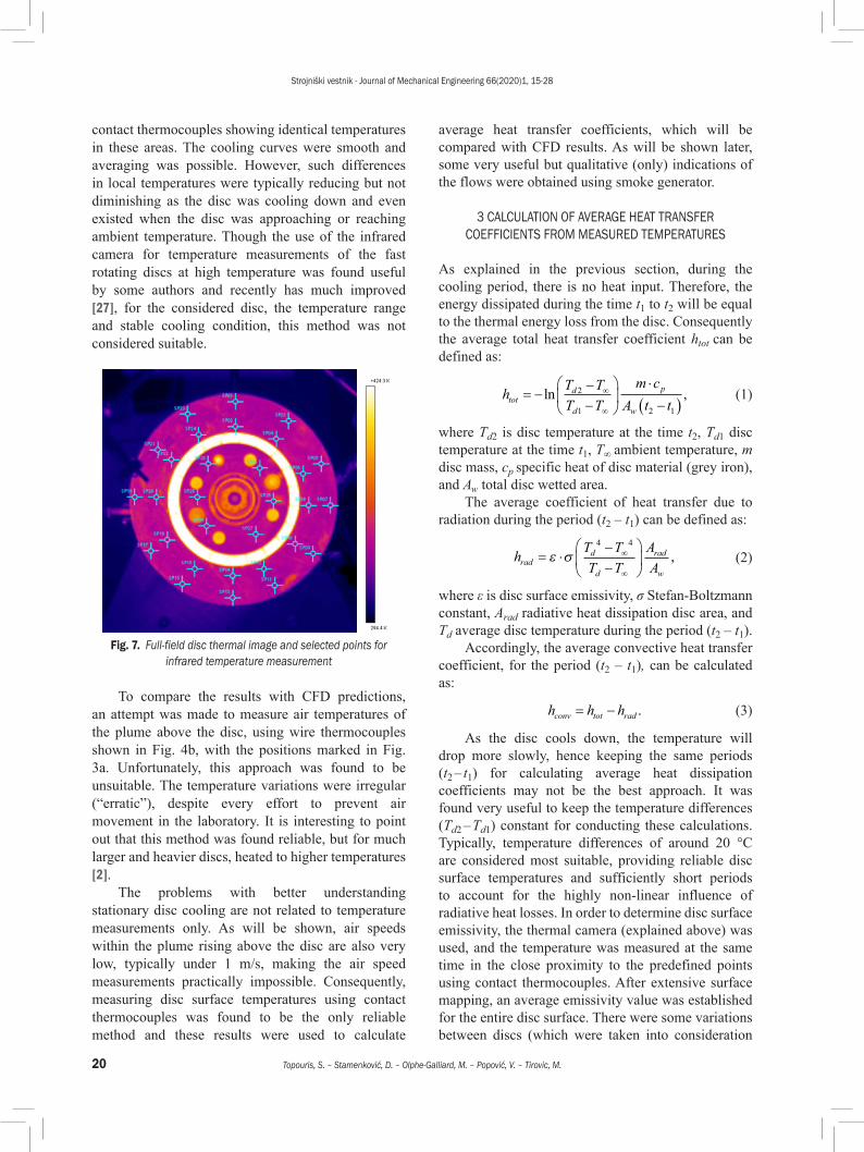
In an attempt to obtain more temperature data across the friction face and hub flange area of the disc, a FLIR A320 thermal imaging camera was also used, with Fig. 7 showing the image and selected points for obtaining temperatures. Unfortunately, this was not providing useful results, as minor differences in disc surface condition lead to small differences in emissivity values, which in turn caused differences in obtained temperature readings. The differences were typically around 5 °C, but sometimes higher, even 10 °C or more, without any reason for the difference (except change in emissivity) and with
Strojniški vestnik - Journal of Mechanical Engineering 66(2020)1, 15-28
20 Topouris, S. – Stamenković, D. – Olphe-Galliard, M. – Popović, V. – Tirovic, M.
contact thermocouples showing identical temperatures in these areas. The cooling curves were smooth and averaging was possible. However, such differences in local temperatures were typically reducing but not diminishing as the disc was cooling down and even existed when the disc was approaching or reaching ambient temperature. Though the use of the infrared camera for temperature measurements of the fast rotating discs at high temperature was found useful by some authors and recently has much improved [27], for the considered disc, the temperature range and stable cooling condition, this method was not considered suitable.
Fig. 7. Full-field disc thermal image and selected points for infrared temperature measurement
To compare the results with CFD predictions, an attempt was made to measure air temperatures of the plume above the disc, using wire thermocouples shown in Fig. 4b, with the positions marked in Fig. 3a. Unfortunately, this approach was found to be unsuitable. The temperature variations were irregular (“erratic”), despite every effort to prevent air movement in the laboratory. It is interesting to point out that this method was found reliable, but for much larger and heavier discs, heated to higher temperatures [2].
The problems with better understanding stationary disc cooling are not related to temperature measurements only. As will be shown, air speeds within the plume rising above the disc are also very low, typically under 1 m/s, making the air speed measurements practically impossible. Consequently, measuring disc surface temperatures using contact thermocouples was found to be the only reliable method and these results were used to calculate
average heat transfer coefficients, which will be compared with CFD results. As will be shown later, some very useful but qualitative (only) indications of the flows were obtained using smoke generator.
3 CALCULATION OF AVERAGE HEAT TRANSFER COEFFICIENTS FROM MEASURED TEMPERATURES
As explained in the previous section, during the cooling period, there is no heat input. Therefore, the energy dissipated during the time t1 to t2 will be equal to the thermal energy loss from the disc. Consequently the average total heat transfer coefficient htot can be defined as:
h T TT T
m cA t ttot
d
d
p
w
= −−−
⋅
−( )∞
∞
ln ,2
1 2 1
(1)
where Td2 is disc temperature at the time t2, Td1 disc temperature at the time t1, T∞ ambient temperature, m disc mass, cp specific heat of disc material (grey iron), and Aw total disc wetted area.
The average coefficient of heat transfer due to radiation during the period (t2 – t1) can be defined as:
h T TT T
AArad
d
d
rad
w
= ⋅−−
∞
∞
ε σ4 4
, (2)
where ε is disc surface emissivity, σ Stefan-Boltzmann constant, Arad radiative heat dissipation disc area, and Td average disc temperature during the period (t2 – t1).
Accordingly, the average convective heat transfer coefficient, for the period (t2 – t1), can be calculated as:
h h hconv tot rad= − . (3)
As the disc cools down, the temperature will drop more slowly, hence keeping the same periods (t2 – t1) for calculating average heat dissipation coefficients may not be the best approach. It was found very useful to keep the temperature differences (Td2 – Td1) constant for conducting these calculations. Typically, temperature differences of around 20 °C are considered most suitable, providing reliable disc surface temperatures and sufficiently short periods to account for the highly non-linear influence of radiative heat losses. In order to determine disc surface emissivity, the thermal camera (explained above) was used, and the temperature was measured at the same time in the close proximity to the predefined points using contact thermocouples. After extensive surface mapping, an average emissivity value was established for the entire disc surface. There were some variations between discs (which were taken into consideration

Strojniški vestnik - Journal of Mechanical Engineering 66(2020)1, 15-28
21Heat Dissipation from Stationary Passenger Car Brake Discs
when processing the data), but the overall average value was found to be ε = 0.82. It should be pointed out that the disc surface was oxidized, covered in fine corrosion after repeated heating and cooling. There were no pads to polish the disc surface, and the contact/rubbing thermocouples covered only small areas and caused little change to the surface emissivity in the contact paths with the disc (as the disc was rotating during the heating period, but the speeds and interface pressures were very low).
4 CFD MODELLING AND COMPARISON WITH EXPERIMENTAL RESULTS
CFD modelling for VW front and rear discs was conducted using CFX code [31].
4.1 CFD Mesh
Fig. 8 depicts a front ventilated disc model, with Fig. 8a showing the air domain, Figs. 8b and c surface mesh on the outboard and inboard side, respectively. Mesh detail in the area of channel entrance at disc inner diameter is shown in Fig. 8d, where very fine mesh with numerous small cells can be observed.
Figs. 9a and b show the rear solid disc, where the mesh did not require that many cells. Mesh statistics for the two discs are included in Table 3.
Table 3. CFD Mesh statistics
CharacteristicsVentilated disc
(fine mesh)Solid disc
Nodes (total) 3,295,654 857,655Elements (total) of which: 12,117,247 3,226,623 Tetrahedral 8,825,745 2,406,319 Pyramids 112 287 Prisms 3,291,390 820,017
The total number of cells was over 12 million for the ventilated and over 3 million for the solid disc. It should be pointed out that such a fine mesh was necessary for modelling the air flow and heat transfer of stationary discs. A much lower number of cells was needed when modelling rotating disc or disc in a cross flow. A K-ε turbulence model was used for both discs, and the results will be first presented alongside qualitative experimental investigations using a smoke generator.
a)
b)
c)
d) Fig. 8. CFD modelling of the ventilated disc; a) air domain,
b) surface mesh (outboard), c) surface mesh (inboard), and d) mesh detail

Strojniški vestnik - Journal of Mechanical Engineering 66(2020)1, 15-28
22 Topouris, S. – Stamenković, D. – Olphe-Galliard, M. – Popović, V. – Tirovic, M.
invisible or air plume direction difficult to understand. As expected, the cooling is most effective in the upper side of the disc and least effective in the channels which are in the horizontal position.
a)
b) Fig. 10. Ventilated disc: a) CFD air velocities, and b) flow (smoke)
pattern using smoke generator
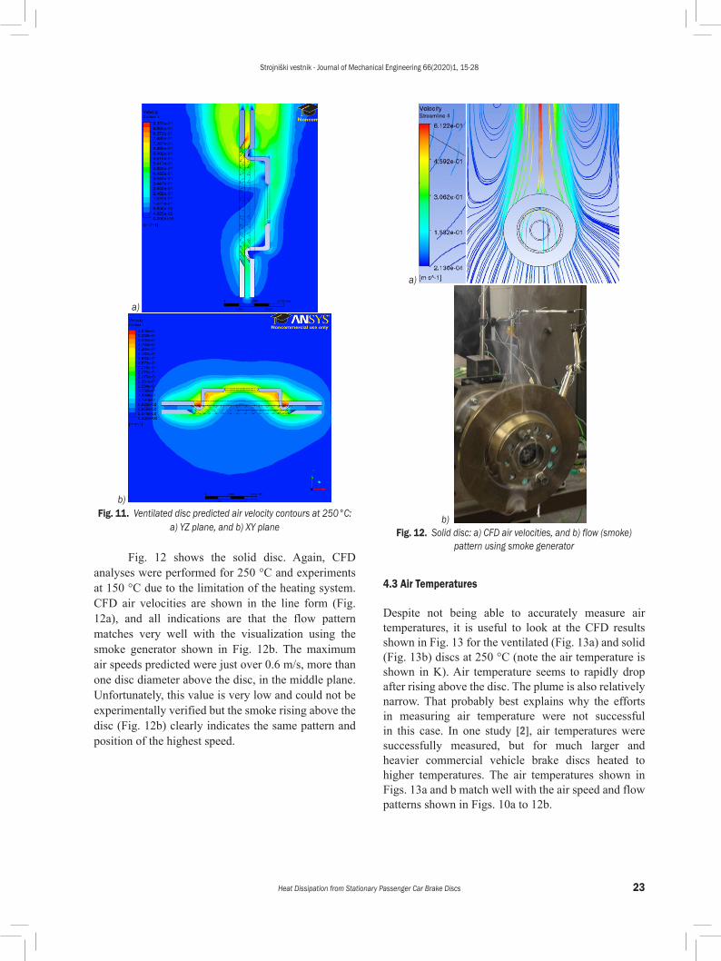
Fig. 11a shows air velocity contours in the vertical plane YZ running through the disc axis, with 11b showing horizontal plane XY, again running through the disc axis. It can be observed that upwards air flow in the swan neck area, at disc inner diameter, blocks air entry into the ventilation channels. This phenomenon (effect) diminishes with a drop in disc temperatures. As a result, convective cooling does not drop as drastically as probably expected with disc cooling, owing to (proportionally) more air flow going through ventilation channels at lower disc temperatures.
a)
b) Fig. 9. CFD Modelling of the solid disc; a) surface mesh
and b) mesh detail
4.2 Air Flow
Fig. 10a shows air velocity contours for the ventilated disc at 250 °C in the middle vertical plane (XZ, see Fig. 8a). It can be seen that the maximum velocity predicted is just over 0.9 m/s; therefore, it was not possible to conduct experimental validation. In order to validate flow pattern, tests were conducted using smoke generator with neutral buoyancy smoke (generated from special oil), with the fine probe releasing the smoke in various areas in the proximity to the disc. Fig. 10b shows the plume rising from the disc faces and channels, which closely resembles the CFD predictions displayed in Fig. 10a. It should be pointed out that, unfortunately, the disc could not be heated to 250 °C, the temperature used for CFD modelling.
The flow air patterns (such as Fig. 10b) are very difficult to photograph and obtain clear flow indications. The best approach established was to take videos and then play them frame by frame and select the clearest pictures with the highest contrast. This approach inevitably reduced picture resolution, with the disc cooling down during filming. The light also played an important part in taking useful images; too much or too little light made the smoke practically
Strojniški vestnik - Journal of Mechanical Engineering 66(2020)1, 15-28
23Heat Dissipation from Stationary Passenger Car Brake Discs
a)
b) Fig. 11. Ventilated disc predicted air velocity contours at 250°C:
a) YZ plane, and b) XY plane
Fig. 12 shows the solid disc. Again, CFD analyses were performed for 250 °C and experiments at 150 °C due to the limitation of the heating system. CFD air velocities are shown in the line form (Fig. 12a), and all indications are that the flow pattern matches very well with the visualization using the smoke generator shown in Fig. 12b. The maximum air speeds predicted were just over 0.6 m/s, more than one disc diameter above the disc, in the middle plane. Unfortunately, this value is very low and could not be experimentally verified but the smoke rising above the disc (Fig. 12b) clearly indicates the same pattern and position of the highest speed.
a)
b) Fig. 12. Solid disc: a) CFD air velocities, and b) flow (smoke)
pattern using smoke generator
4.3 Air Temperatures
Despite not being able to accurately measure air temperatures, it is useful to look at the CFD results shown in Fig. 13 for the ventilated (Fig. 13a) and solid (Fig. 13b) discs at 250 °C (note the air temperature is shown in K). Air temperature seems to rapidly drop after rising above the disc. The plume is also relatively narrow. That probably best explains why the efforts in measuring air temperature were not successful in this case. In one study [2], air temperatures were successfully measured, but for much larger and heavier commercial vehicle brake discs heated to higher temperatures. The air temperatures shown in Figs. 13a and b match well with the air speed and flow patterns shown in Figs. 10a to 12b.

Strojniški vestnik - Journal of Mechanical Engineering 66(2020)1, 15-28
24 Topouris, S. – Stamenković, D. – Olphe-Galliard, M. – Popović, V. – Tirovic, M.
a)
b) Fig. 13. Air temperature contour in XZ plane for discs at 250°C:
a) ventilated disc, and b) solid disc
4.4 Heat Transfer Coefficients
CFD analyses also enabled predictions of the local and average convective heat transfer coefficients over the disc surfaces, with Fig. 14 showing the ventilated and Fig. 15 solid disc. For both designs, it is clear that convective heat dissipation is more effective from the upper part of the disc, as would be expected. On the outboard side of the disc, the effect of the hub (top hat) can also be observed. The flow is blocked, and there is a reduction of the convective cooling in the middle of the disc, above the hub. However, this effect is not present on the inboard side of the disc friction faces. Maximum values of the heat transfer coefficient reach approx. 14.8 W/(m2K) for the ventilated disc (Fig. 14) and 8.2 W/(m2K) for the solid disc (Fig. 15), but these values of the convective heat transfer coefficients are limited to very small areas with no practical significance for disc cooling. For both designs, the highest values covering larger disc areas are around 5 W/(m2K). CFD analyses enabled automatic
calculations of average values for the convective heat dissipation coefficients, from the distributions shown in Figs. 14 and 15.
Fig. 14. Predicted convective heat transfer coefficient distribution for ventilated disc
Fig. 15. Predicted convective heat transfer coefficient distribution for solid disc
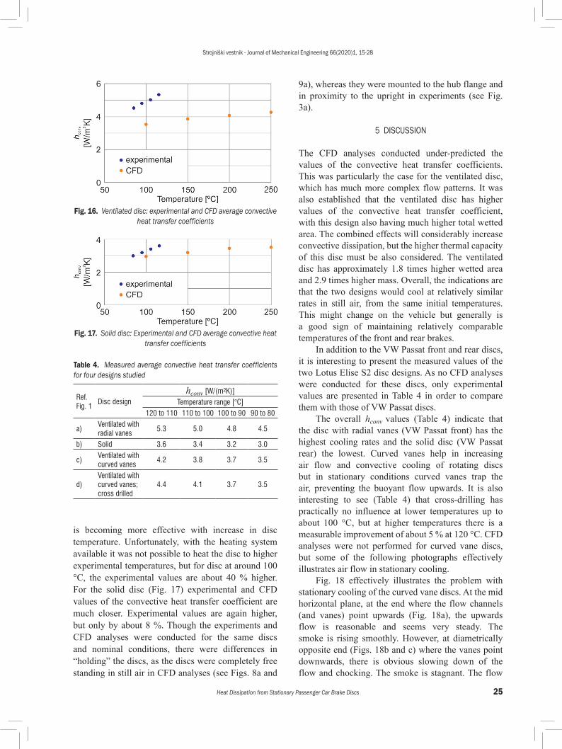
Experimental investigations enabled only the extractions of average convective heat dissipation coefficients, from the average cooling curves (measured surface temperatures during disc cooling). The measurements of disc surface temperatures proved to be very repeatable and reliable. The procedure for calculating average convective heat transfer coefficients from cooling curves was explained earlier, which now enables for these values to be compared with CFD results. To cover the temperature range, CFD analyses had to be repeated for lower temperatures. The comparisons presented in Figs. 16 and 17 for ventilated and solid discs respectively, show quite interesting phenomena. For the ventilated disc (Fig. 16), the average convective heat transfer coefficients calculated from the measured cooling curves have higher values than CFD predictions. The gradient is also steeper, the cooling
Strojniški vestnik - Journal of Mechanical Engineering 66(2020)1, 15-28
25Heat Dissipation from Stationary Passenger Car Brake Discs
is becoming more effective with increase in disc temperature. Unfortunately, with the heating system available it was not possible to heat the disc to higher experimental temperatures, but for disc at around 100 °C, the experimental values are about 40 % higher. For the solid disc (Fig. 17) experimental and CFD values of the convective heat transfer coefficient are much closer. Experimental values are again higher, but only by about 8 %. Though the experiments and CFD analyses were conducted for the same discs and nominal conditions, there were differences in “holding” the discs, as the discs were completely free standing in still air in CFD analyses (see Figs. 8a and
9a), whereas they were mounted to the hub flange and in proximity to the upright in experiments (see Fig. 3a).
5 DISCUSSION
The CFD analyses conducted under-predicted the values of the convective heat transfer coefficients. This was particularly the case for the ventilated disc, which has much more complex flow patterns. It was also established that the ventilated disc has higher values of the convective heat transfer coefficient, with this design also having much higher total wetted area. The combined effects will considerably increase convective dissipation, but the higher thermal capacity of this disc must be also considered. The ventilated disc has approximately 1.8 times higher wetted area and 2.9 times higher mass. Overall, the indications are that the two designs would cool at relatively similar rates in still air, from the same initial temperatures. This might change on the vehicle but generally is a good sign of maintaining relatively comparable temperatures of the front and rear brakes.
In addition to the VW Passat front and rear discs, it is interesting to present the measured values of the two Lotus Elise S2 disc designs. As no CFD analyses were conducted for these discs, only experimental values are presented in Table 4 in order to compare them with those of VW Passat discs.
The overall hconv values (Table 4) indicate that the disc with radial vanes (VW Passat front) has the highest cooling rates and the solid disc (VW Passat rear) the lowest. Curved vanes help in increasing air flow and convective cooling of rotating discs but in stationary conditions curved vanes trap the air, preventing the buoyant flow upwards. It is also interesting to see (Table 4) that cross-drilling has practically no influence at lower temperatures up to about 100 °C, but at higher temperatures there is a measurable improvement of about 5 % at 120 °C. CFD analyses were not performed for curved vane discs, but some of the following photographs effectively illustrates air flow in stationary cooling.
Fig. 18 effectively illustrates the problem with stationary cooling of the curved vane discs. At the mid horizontal plane, at the end where the flow channels (and vanes) point upwards (Fig. 18a), the upwards flow is reasonable and seems very steady. The smoke is rising smoothly. However, at diametrically opposite end (Figs. 18b and c) where the vanes point downwards, there is obvious slowing down of the flow and chocking. The smoke is stagnant. The flow
Fig. 16. Ventilated disc: experimental and CFD average convective heat transfer coefficients
Fig. 17. Solid disc: Experimental and CFD average convective heat transfer coefficients
Table 4. Measured average convective heat transfer coefficients for four designs studied
Ref. Fig. 1
Disc designhconv [W/(m2K)]
Temperature range [°C]120 to 110 110 to 100 100 to 90 90 to 80
a)Ventilated with radial vanes
5.3 5.0 4.8 4.5
b) Solid 3.6 3.4 3.2 3.0
c)Ventilated with curved vanes
4.2 3.8 3.7 3.5
d)Ventilated with curved vanes; cross drilled
4.4 4.1 3.7 3.5

Strojniški vestnik - Journal of Mechanical Engineering 66(2020)1, 15-28
26 Topouris, S. – Stamenković, D. – Olphe-Galliard, M. – Popović, V. – Tirovic, M.
through the bottom and top of the ventilation channels is not particularly good either.
Fig. 19 presents the cross-drilled disc, showing a similar flow problems to the standard, non-drilled disc (Fig. 18). At the mid horizontal plane, at the end where the flow channels (and vanes) point upwards (Fig. 19a), the flow is reasonable and seems very steady, similarly to the non-drilled disc (Fig. 18a). However,
at the diametrically opposite end (Figs. 19b and c), there is obvious obstruction and chocking. To a certain degree the holes drilled through friction faces help the flow, and in Fig. 19c there is a clear view of the smoke rising upwards through the cross-drilled holes. It is reasonable to assume that in some areas the holes will also provide air entry, helping the overall cooling. The effects are expected to be more pronounced with
a) b) c) Fig. 18. Curved vane standard disc smoke tests: a) flow channels pointing upwards, b) and c) flow channels pointing downwards
a) b) c) Fig. 19. Curved vane cross-drilled disc smoke tests; a) flow channels pointing upwards, b) and c) flow channels pointing downwards
Strojniški vestnik - Journal of Mechanical Engineering 66(2020)1, 15-28
27Heat Dissipation from Stationary Passenger Car Brake Discs
increased buoyancy, and the values in Table 4 prove that, with the cross-drilled disc showing superior cooling characteristics at higher temperatures (in comparison to the standard disc). The flow through the bottom and top of the ventilation channels can also be marginally helped with cross-drilling.
6 CONCLUSIONS
Experimental investigation of the heat dissipation from stationary discs was successful in ensuring repeatable and accurate measurement and prediction of the total, convective and radiative heat dissipation coefficients. The values compare favourably with CFD analyses, though the differences are somewhat pronounced for the ventilated discs. The speeds of the hot air rising above the disc are far too low and flow pattern narrow and relatively irregular, making the validation of air speeds and air temperatures practically impossible. However, the use of smoke generator (with neutral buoyancy smoke) and suitable probe was very useful in qualitatively validating the flow patterns.
Convective heat transfer coefficients increase with temperature but the values are very low, typically between 3 W/(m2K) and 5 W/(m2K) for the disc designs and temperature range analysed. As expected, out of the four designs studied, the disc with radial vanes has highest convective heat dissipation coefficient and the solid disc the lowest. The reduction is about 30 %, with the disc with curved vanes values being about 20 % lower than for the disc with radial vanes.
Low values of convective heat transfer coefficients indicate low dissipated energy (heat), in particular for the solid disc. Consequently, cooling times are very long and the contribution of the other two heat dissipation modes, conduction and radiation, higher. At high disc temperatures (>400 °C), radiative losses in stable conditions can be an order of the magnitude higher than convective.
When installed on the vehicle, with the addition of the calliper assembly, wheel, mudguard and dust shield, the cooling of brake discs is likely to be even further reduced. Future work is concentrated in addressing this challenge in two ways, by improving CFD modelling and equipping the thermal spin rig with induction heater to heat the disc much more rapidly and to much higher temperatures.
Cross drilling of the disc with curved vanes seems to only marginally improve static cooling, predominantly at higher temperatures.
7 ACKNOWLEDGEMENTS
Some of the presented results are part of a project financed by the Serbian Ministry of Education, Science and Technological Development (Project TR 35045 - “Scientific-Technological Support to Enhancing the Safety of Special Road and Rail Vehicles”).
8 NOMENCLATURES
Aw total disc wetted area, [m2]Arad radiative heat dissipation disc area, [m2]cp specific heat of disc material (grey iron), [J/(kgK)]htot total average heat transfer coefficient, [W/(m2K)]hconv average convective heat transfer coefficient, [W/(m2K)]hrad average radiative heat transfer coefficient, [W/(m2K)]m disc mass, [kg]Td average disc temperature during time period (t2 – t1), [K]Td1 disc temperature at the time t1, [K]Td2 disc temperature at the time t2, [K]T∞ ambient air temperature, [K]t time, [s]ε disc surface emissivity, [-]σ Stefan-Boltzmann constant (5.67·10-8), [W/(m2K2)]
9 REFERENCES
[1] UN Regulation No. 13-H (Revision 4) (2018). Uniform Provisions Concerning the Approval of Passenger Cars with Regard to Braking. United Nations, Geneve.
[2] Stevens, K. (2013). An Investigation into Heat Dissipation from a Stationary Commercial Vehicle Brake Disc in Parked Conditions, EngD Thesis, Cranfield University, Cranfield.
[3] Wagner, C. (1948). Heat transfer from a rotating disk to ambient air. Journal of Applied Physics, vol. 19, no. 9, p. 837-839, DOI:10.1063/1.1698216.
[4] Cobb, E.C., Saunders, O.A. (1956). Heat transfer from a rotating disk. Proceedings of the Royal Society A: Mathematical, Physical and Engineering Sciences, vol. 236, no. 1206, p. 343-351, DOI:10.1098/rspa.1956.0141.
[5] Richardson, P.D., Saunders, O.A. (1963). Studies of flow and heat transfer associated with a rotating disc. Journal of Mechanical Engineering Science, vol. 5, no. 4, p. 336-342, DOI:10.1243/JMES_JOUR_1963_005_044_02.
[6] Newcomb, T.P. (1959). Transient temperatures attained in disk brakes. British Journal of Applied Physics, vol. 10, no. 7, p. 339-340, DOI: 10.1088/0508-3443/10/7/311.
Strojniški vestnik - Journal of Mechanical Engineering 66(2020)1, 15-28
28 Topouris, S. – Stamenković, D. – Olphe-Galliard, M. – Popović, V. – Tirovic, M.
[7] Newcomb, T.P., Spurr, R.T. (1967). Braking of Road Vehicles. Chapman & Hall, London.
[8] Grkić, A., Mikluc, D., Muždeka, S., Arsenić, Ž., Duboka, Č. (2015). A Model for the estimation of brake interface temperature. Strojniški vestnik - Journal of Mechanical Engineering, vol. 61, no. 6, p. 392-398, DOI:10.5545/sv-jme.2014.2364.
[9] Noyes, R.N., Vickers, P.T. (1969). Prediction of surface temperatures in passenger car disc brakes. SAE Technical Paper, no. 690457, DOI:10.4271/690457.
[10] Morgan, S., Dennis, R.W. (1972). A theoretical prediction of disc brake temperatures and a comparison with experimental data, SAE Technical Paper, no. 720090, DOI:10.4271/720090.
[11] Limpert, R. (1975). Cooling analysis of disc brake rotors. SAE Technical Paper, no. 751014, DOI:10.4271/751014.
[12] Sisson, A.E. (1978). Thermal analysis of vented brake rotors. SAE Technical Paper, no. 780352, DOI:10.4271/780352.
[13] Daudi, A.R. (1999). 72 curved fins and air director idea increase airflow through brake rotors. SAE Technical Paper, no. 1999-01-0140, DOI:10.4271/1999-01-0140.
[14] Galindo-Lopez, C.H., Tirovic, M. (2008). Understanding and improving the convective cooling of brake discs with radial vanes. Proceedings of the Institution of Mechanical Engineers, Part D: Journal of Automobile Engineering, vol. 222, no. 7, p. 1211-1229, DOI:10.1243/09544070JAUTO594.
[15] Galindo-Lopez, C.H., Tirovic, M. (2013). Maximizing heat dissipation from ventilated wheel-hub-mounted railway brake discs. Proceedings of the Institution of Mechanical Engineers, Part F: Journal of Rail and Rapid Transit, vol. 227, no. 3, p. 269-285, DOI:10.1177/0954409712462337.
[16] Pevec, M., Potrc. I., Bombek, G., Vranesevic, D. (2012). Prediction of the cooling factors of a vehicle brake disc and its influence on the results of a thermal numerical simulation. International Journal of Automotive Technology, vol. 13, no. 5, p. 725-733, DOI:10.1007/s12239-012-0071-y.
[17] Son, J.K., Jung, Y.-S., Jeon, H.-H. (2018). Optimization analysis and design of brake cooling system. EuroBrake 2018 Conference Proceedings, paper EB2018-SVM-003.
[18] Stevens, K., Tirovic, M. (2018). Heat dissipation from a stationary brake disc, Part 1: Analytical modelling and experimental investigations. Proceedings of the Institution of Mechanical Engineers, Part C: Journal of Mechanical Engineering Science, vol. 232, no. 9, p. 1707-1733, DOI:10.1177/0954406217707983.
[19] Tirovic, M., Stevens, K. (2018). Heat dissipation from a stationary brake disc, Part 2: CFD modelling and experimental validations. Proceedings of the Institution of Mechanical Engineers, Part C: Journal of Mechanical
Engineering Science, vol. 232, no. 10, p. 1898-1924, DOI:10.1177/0954406217707984.
[20] McAdams, W.H. (1954). Heat Transfer. McGraw-Hill, New York.[21] Morgan, V.T. (1975). The overall convective heat transfer from
smooth circular cylinders. Advances in Heat Transfer, vol. 11, p. 199-264, DOI:10.1016/S0065-2717(08)70075-3.
[22] Churchill, S.W., Chu, H.H.S. (1975). Correlating equations for laminar and turbulent free convection from a horizontal cylinder. International Journal of Heat Mass Transfer, vol. 18, no. 9, p. 1049-1053, DOI:10.1016/0017-9310(75)90222-7.
[23] Necati Özisik, M. (1989). Heat Transfer: A Basic Approach. McGraw-Hill, New York.
[24] Tirovic, M., Voller, G.P. (2005). Interface pressure distributions and thermal contact resistance of a bolted joint. Proceedings of the Royal Society A: Mathematical, Physical and Engineering Sciences, vol. 461, no. 2060, p. 2339-2354, DOI:10.1098/rspa.2005.1452.
[25] Teimourimanesh, S., Vernersson, T., Lundén, R. (2014). Modelling of temperatures during railway tread braking: Influence of contact conditions and rail cooling effect. Proceedings of the Institution of Mechanical Engineers, Part F: Journal of Rail and Rapid Transit, vol. 228, no. 1, p. 93-109, DOI:10.1177/0954409712465696.
[26] Eisengräber, R., Grochowicz, J., Schuster, M., Augsburg, K., Koch, L. (1999). Comparison of different methods for the determination of the friction temperature of disc brakes. SAE Technical Paper, no. 1999-01-0138, DOI:10.4271/1999-01-0138.
[27] Dufrenoy, P., Berte, E., Witz, J-F., Desplanques, Y. (2018). A new camera for quantitative measurements of temperature and emissivity during braking. EuroBrake Conference Proceedings, paper EB2018-VDT-033.
[28] Grieve, D.G., Barton, D.C., Crolla, D.A., Buckingham, J.T. (1998). Design of a lightweight automotive brake disc using finite element and Taguchi techniques. Proceedings of the Institution of Mechanical Engineers, Part D: Journal of Automobile Engineering, vol. 212, no. 4, p. 245-254, DOI:10.1243/0954407981525939.
[29] Tang, J., Bryant, D., Qi, H. (2018). Experimental investigation of the dynamic thermal deformation and judder of a ventilated disc brake. EuroBrake Conference Proceedings, paper EB2018-FBR-002.
[30] Topouris, S. (2017). Design and Optimisation of a High Performance Lightweight Monoblock Cast Iron Brake Disc, PhD Thesis. Cranfield University, Cranfield.
[31] Olphe-Galliard, M. (2011). Study of Thermodynamics and Fluid Mechanics Involved in the Cooling of Brake Discs, MSc Thesis. Cranfield University, Cranfield.