HEALY SYSTEMS VP1000 DISPENSER MOUNTED · PDF filehealy systems vp1000 dispenser mounted...
45
HEALY SYSTEMS VP1000 DISPENSER MOUNTED VACUUM PUMP INSTALLATION & SERVICE GUIDE FOR MULTIPRODUCT DISPENSERS Rev. 07-19-03 CWG HEALY SYSTEMS, INC. – 18 HAMPSHIRE DRIVE – HUDSON, NH 03051 TEL: (603) 882-2472 FAX: (603) 882-5189
Transcript of HEALY SYSTEMS VP1000 DISPENSER MOUNTED · PDF filehealy systems vp1000 dispenser mounted...

HEALY SYSTEMS VP1000 DISPENSER MOUNTED VACUUM PUMP
INSTALLATION & SERVICE GUIDE FOR
MULTIPRODUCT DISPENSERS
Rev. 07-19-03 CWG
HEALY SYSTEMS, INC. – 18 HAMPSHIRE DRIVE – HUDSON, NH 03051 TEL: (603) 882-2472 FAX: (603) 882-5189
INDEX SECTION ONE: INSTALLATION PAGE
DESCRIPTION OF OPERATION OF THE VP1000 VACUUM PUMP AND INTERFACE MODULES 1 & 2
TOOLS REQUIRED FOR INSTALLATION OF THE VP1000 DISPENSER MOUNTED VACUUM PUMP 3
MECHANICAL REQUIREMENTS FOR INSTALLATION OF THE VP1000 DISPENSER MOUNTED VACUUM PUMP 4
TYPICAL MECHANICAL INSTALLATION DRAWING 5
OPTIONAL VAPOR INSTALLATION KIT HEALY PART# Z071V 6
ELECTRICAL REQUIREMENTS FOR INSTALLATION OF THE VP1000 DISPENSER MOUNTED VACUUM PUMP 7
TYPICAL ELECTRICAL INSTALLATION DRAWING 8
OPTIONAL ELECTRICAL INSTALLATION KIT HEALY PART# Z070E 9
TYPICAL INSTALLATIONS FOR HEALY POTTED CONDUIT ASSEMBLIES 10
WIRING THE 1316 POTTED CONDUIT ASSEMBLY TO THE MC100 AND RCS120A-4222D INTERFACE MODULES 11
WIRING INSTRUCTION FOR THE 1360A INTERFACE MODULE/CABLE ASSEMBLY FOR A BLENDING OR NON-BLENDING DISPENSER UTILIZING EITHER VDC OR VAC SOLENOIDS 12
WIRING INSTRUCTION FOR THE 1368A INTERFACE MODULE/CABLE ASSEMBLY FOR THE GILBARCO ENCORE BLENDING DISPENSER UTILIZING 120 VAC SOLENOIDS (MANUFACTURED BEFORE MAY 2003)
13
WIRING INSTRUCTION FOR THE 1369A INTERFACE MODULE/CABLE ASSEMBLY FOR THE GILBARCO ENCORE 300 NON-BLENDING DISPENSER UTILIZING 120 VAC SOLENOIDS (MANUFACTURED BEFORE MAY 2003) 14
WIRING INSTRUCTION FOR THE 1373A INTERFACE MODULE/CABLE ASSEMBLY FOR THE GILBARCO ENCORE 300 BLENDING OR 3-PRODUCT DISPENSER UTILIZING 24 VDC SOLENOIDS (MANUFACTURED AFTER APRIL 25, 2003)
15
WIRING INSTRUCTION FOR THE 1365A INTERFACE MODULE/CABLE ASSEMBLY FOR THE WAYNE 3V AND OVATION SERIES DISPENSER UTILIZING THE I GEM COMPUTER 16
WIRING INSTRUCTION FOR THE 1363A INTERFACE MODULE/CABLE ASSEMBLY FOR THE WAYNE 1VISTA AND 2VISTA SERIES ELECTRONIC-BLENDING DISPENSER UTILIZING 24VDC SOLENOIDS
17
WIRING INSTRUCTION FOR THE 1354A INTERFACE MODULE/CABLE ASSEMBLY FOR THE WAYNE NON-BLENDING DISPENSER UTILIZING 120VAC SOLENOIDS 18
WIRING INSTRUCTION FOR THE 1362A INTERFACE MODULE/CABLE ASSEMBLY FOR THE TOKHEIM PREMIER C BLENDING DISPENSER
19
WIRING INSTRUCTION FOR THE 1372A INTERFACE MODULE/CABLE ASSEMBLY FOR THE TOKHEIM BLENDING DISPENSER UTILIZING BOTH 24VDC AND 120VAC SOLENOIDS 20
ADJUSTING THE RCS120A-4222D INTERFACE MODULE 21
HOW TO INDENTIFY HEALY DISPENSER INTERFACE MODULES 22
TROULBLESHOOTING GUIDE 23,24,25 & 26
VP1000VR VANE AND ROTOR REPLACEMENT KIT 27 & 28
VP1000 VACUUM PERFORMANCE TEST PROCEDURE 29
FIELD REPAIR INSTRUCTIONS 600/800 SERIES NOZZLES 30,31 & 32
HOW TO ADJUST THE A/L ON THE 600/800 SERIES NOZZLE 33
MODEL 6059 A/L SPOUT ADAPTER INSTRUCTIONS 34
MODEL 8034-1 A/L TEST SLEEVE INSTRUCTIONS 35
FIELD REPAIR INSTRUCTIONS FOR 75B SERIES HOSES 36
8701VV BREAKAWAY ASSEMBLY AND INSTALLATION INSTRUCTIONS 37
8701VV BREAKAWAY ASSEMBLY PULL FORCE TEST 38
SCHEDULED MAINTENANCE INSTRUCTIONS FOR THE 600 & 800 NOZZLES WITH THE VP1000 VACUUM PUMP 39 & 40
HEALY SYSTEMS LIMITED WARRANTY 41
SYSTEMS, INC. 18 Hampshire Drive
Hudson, NH 03051 USA Tel: (603) 882-2472 Fax: (603) 882-5189
Web Site: www.healysystems.com mail: [email protected] (Rev 7-19-03 CWG)

Description of Operation of the Healy Systems VP100 0 Vacuum Pump and Interface Modules
VP1000 PUMP The Healy Systems VP1000 vacuum pump typical installation location is in the lower hydraulic area of self-contained gasoline pump or dispenser. It works in conjunction with an associated electronic module and Healy Systems Vapor Recovery nozzles and ‘hanging hardware’.
• Specifications: 1/8 Hp, 120 VAC input, 2 A AC • Mounting: The preferred installation for best performance is using the bracket
supplied, with the inlet facing upward, toward the top of the dispenser (See drawing below). If other mounting positions are desired due to mechanical constraints within the dispenser, call Healy Systems at 603-882-2472, during normal business hours of 8 a.m., to 5 p.m. Eastern time for available options.
• Contains an internal bypass valve to regulate the vacuum produced to 70 –100 inches water column.
• Contains low temperature activation circuits that turn the motor on at slow speed when the temperature drops below 40°F. This preven ts freezing of any moisture inside the pump but is not sufficient to cause a strong vacuum.
• Operates only with input signals from an associated module, cannot be operated ‘stand alone’.
• Operates at only two speeds: slow speed in response to one input (red wire) being activated, or high speed if both input signals (both red wires) being activated.
• Contains over and under voltage and temperature devices that will shut off the motor if either condition exists and AUTOMATICALLY return power when normal operating conditions are restored.
Page 1
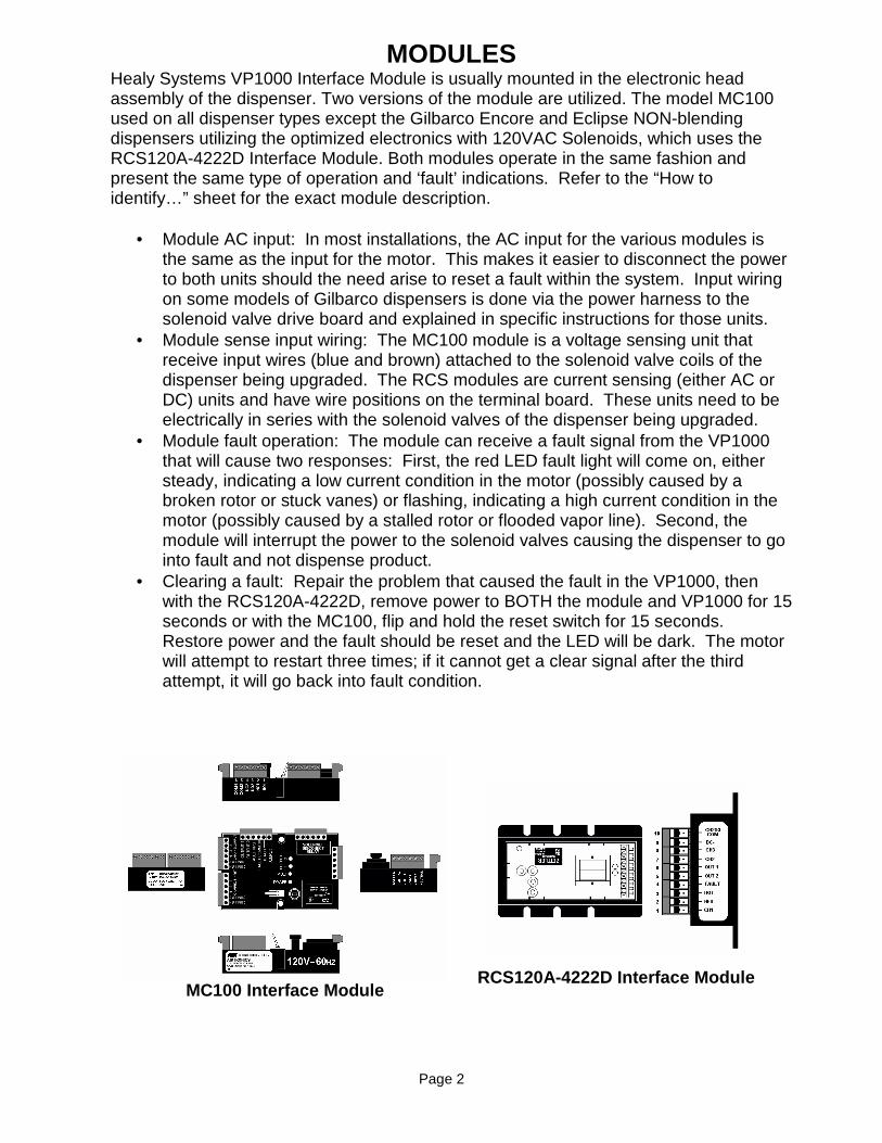
MODULES Healy Systems VP1000 Interface Module is usually mounted in the electronic head assembly of the dispenser. Two versions of the module are utilized. The model MC100 used on all dispenser types except the Gilbarco Encore and Eclipse NON-blending dispensers utilizing the optimized electronics with 120VAC Solenoids, which uses the RCS120A-4222D Interface Module. Both modules operate in the same fashion and present the same type of operation and ‘fault’ indications. Refer to the “How to identify…” sheet for the exact module description.
• Module AC input: In most installations, the AC input for the various modules is the same as the input for the motor. This makes it easier to disconnect the power to both units should the need arise to reset a fault within the system. Input wiring on some models of Gilbarco dispensers is done via the power harness to the solenoid valve drive board and explained in specific instructions for those units.
• Module sense input wiring: The MC100 module is a voltage sensing unit that receive input wires (blue and brown) attached to the solenoid valve coils of the dispenser being upgraded. The RCS modules are current sensing (either AC or DC) units and have wire positions on the terminal board. These units need to be electrically in series with the solenoid valves of the dispenser being upgraded.
• Module fault operation: The module can receive a fault signal from the VP1000 that will cause two responses: First, the red LED fault light will come on, either steady, indicating a low current condition in the motor (possibly caused by a broken rotor or stuck vanes) or flashing, indicating a high current condition in the motor (possibly caused by a stalled rotor or flooded vapor line). Second, the module will interrupt the power to the solenoid valves causing the dispenser to go into fault and not dispense product.
• Clearing a fault: Repair the problem that caused the fault in the VP1000, then with the RCS120A-4222D, remove power to BOTH the module and VP1000 for 15 seconds or with the MC100, flip and hold the reset switch for 15 seconds. Restore power and the fault should be reset and the LED will be dark. The motor will attempt to restart three times; if it cannot get a clear signal after the third attempt, it will go back into fault condition.
Page 2
MC100 Interface Module RCS120A-4222D Interface Module

Tools Required for Installation of VP1000 Dispenser Mounted Vacuum Pump
¼” or 3/8” Ratchet set w/Sockets ¼” through 9/16” + 3” Extension 9” Lineman’s Pliers Assorted Open End Wrenches ¼” through ¾” Wire Cutters/Strippers 1 1/8” Sheet Metal Hole Punch (for Potted Conduit Assembly) 3/8” Drill Assembly Assorted Drill Bits 1/16” through 7/16” Assorted Screwdrivers (Flat blade-one must be 1/8” wide) ½” (5/8” O.D.) Copper Tube Bending Tool ½” (5/8” O.D.) Copper Flaring Tool Copper Tubing Cutter Electrical Multi-meter 12” adjustable Wrench 18” Channellock Pliers (2) 18” Pipe Wrench Hand Pipe Threader (for up to 1” pipe) Pipe Cutter (for up to 1” pipe) Tape Measure Thread Sealing Compound O-Ring Lubricant
Page 3

Mechanical Requirements for Installation of VP1000 Dispenser Mounted Vacuum Pump
(Can vary depending on dispenser make and model)
Customer Supplies: Multi-product Dispenser – preferably Balance Ready
Equipment from Healy Systems:
VP1000A (for NON-BLENDERS), VP1000B (for ELECTRONIC BLENDING) or VP1000C (for WAYNE 3V STYLED ELECTRONIC DISPENSERS) Dispenser Mounted Vacuum Pump, Includes Universal Mounting Bracket and Interface Module
Installing Contractor Supplies:
Vapor Plumbing (Approximate) QTY. Description 3 ½” GALV. close nipple NPT 2 ½” GALV. Tee 2 ½” GALV. Elbow 1 ½” GALV. Union 1 ½” x 1½” GALV. Nipple 1 ½” x ¼” GALV. Reducing bushing 1 ¼” GALV. Pipe plug 4 ½” NPT x ½” (5/8” O.D.) flare reducing coupling 2 3/8” NPT x ½” (5/8” O.D.) flare reducing coupling 4 ½” (5/8” O.D.) Flare Nut 1 ½” UL Listed Ball Valve 1 12’ length of ½” (5/8” O.D.) copper tubing (will cut to correct lengths) Purpose is to connect the existing vapor piping from one or both sides of the dispenser to the VP1000 inlet on the pump with a ball valve for isolating the dispenser from the piping and a Tee with a ¼” opening for a 0” to 100” water column gauge. See Figure 1 & 2 typical piping layout drawing.
NOTE: ALL DISPENSER INTERIOR VAPOR PIPING MUST MAIN TAIN PROPER DOWN-SLOPE FROM THE EXISTING DISPENSER PIPING INTO THE VP1000 INLET AND FROM THE OUTLET OF THE VP1000 TO THE EXISTING UNDERGROUND PIPING. TRAPS IN THE VAPOR PIPING CAN AFFECT PERFORMANCE AND WILL VOID T HE WARRANTY. OPTION: Healy Systems has a Vapor Install Kit available. Order Part Number Z071V. See Figure 3 for Z071V Vapor Install Kit Details. Page 4
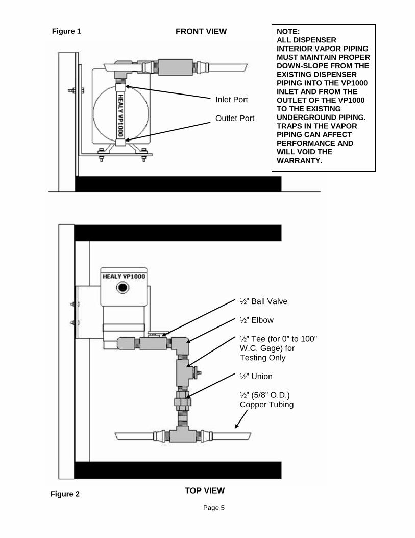
Figure 1
FRONT VIEW
Inlet Port Outlet Port
½” Ball Valve ½” Elbow ½” Tee (for 0” to 100” W.C. Gage) for Testing Only ½” Union ½” (5/8” O.D.) Copper Tubing
NOTE: ALL DISPENSER INTERIOR VAPOR PIPING MUST MAINTAIN PROPER DOWN-SLOPE FROM THE EXISTING DISPENSER PIPING INTO THE VP1000 INLET AND FROM THE OUTLET OF THE VP1000 TO THE EXISTING UNDERGROUND PIPING. TRAPS IN THE VAPOR PIPING CAN AFFECT PERFORMANCE AND WILL VOID THE WARRANTY.
TOP VIEW Figure 2
Page 5

OPTIONAL: Figure 3
Vapor Installation Kit Healy Part # Z071V
Healy Systems has developed a universal styled vapo r piping installation kit. It consists of 12’ of 5/8” O.D. copper tubing, ½” ball valve, ½” x ½” x ¼” Tee and enough straight and 90 °°°° ½” flare fittings to connect to the existing pipin g in the dispenser and to the vapor riser in the containment sump.
NOTE: ALL DISPENSER INTERIOR VAPOR PIPING MUST MAINTAIN P ROPER DOWN-SLOPE FROM THE EXISTING DISPENSER PIPING INTO THE VP1000 INLET AND FROM THE OUTLET OF THE VP1000 TO THE EXISTING UNDERGROUND PIPING. TRAPS IN THE VAPOR PIPING CAN A FFECT PERFORMANCE AND WILL VOID THE WARRANTY.
Page 6
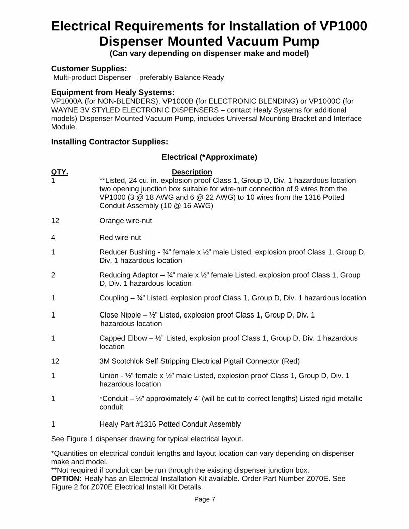
Electrical Requirements for Installation of VP1000 Dispenser Mounted Vacuum Pump
(Can vary depending on dispenser make and model)
Customer Supplies: Multi-product Dispenser – preferably Balance Ready
Equipment from Healy Systems: VP1000A (for NON-BLENDERS), VP1000B (for ELECTRONIC BLENDING) or VP1000C (for WAYNE 3V STYLED ELECTRONIC DISPENSERS – contact Healy Systems for additional models) Dispenser Mounted Vacuum Pump, includes Universal Mounting Bracket and Interface Module.
Installing Contractor Supplies:
Electrical (*Approximate)
QTY. Description 1 **Listed, 24 cu. in. explosion proof Class 1, Group D, Div. 1 hazardous location
two opening junction box suitable for wire-nut connection of 9 wires from the VP1000 (3 @ 18 AWG and 6 @ 22 AWG) to 10 wires from the 1316 Potted Conduit Assembly (10 @ 16 AWG)
12 Orange wire-nut 4 Red wire-nut
1 Reducer Bushing - ¾” female x ½” male Listed, explosion proof Class 1, Group D, Div. 1 hazardous location
2 Reducing Adaptor – ¾” male x ½” female Listed, explosion proof Class 1, Group D, Div. 1 hazardous location
1 Coupling – ¾” Listed, explosion proof Class 1, Group D, Div. 1 hazardous location 1 Close Nipple – ½” Listed, explosion proof Class 1, Group D, Div. 1 hazardous location
1 Capped Elbow – ½” Listed, explosion proof Class 1, Group D, Div. 1 hazardous location
12 3M Scotchlok Self Stripping Electrical Pigtail Connector (Red)
1 Union - ½” female x ½” male Listed, explosion proof Class 1, Group D, Div. 1 hazardous location
1 *Conduit – ½” approximately 4’ (will be cut to correct lengths) Listed rigid metallic conduit
1 Healy Part #1316 Potted Conduit Assembly
See Figure 1 dispenser drawing for typical electrical layout.
*Quantities on electrical conduit lengths and layout location can vary depending on dispenser make and model. **Not required if conduit can be run through the existing dispenser junction box. OPTION: Healy has an Electrical Installation Kit available. Order Part Number Z070E. See Figure 2 for Z070E Electrical Install Kit Details.
Page 7
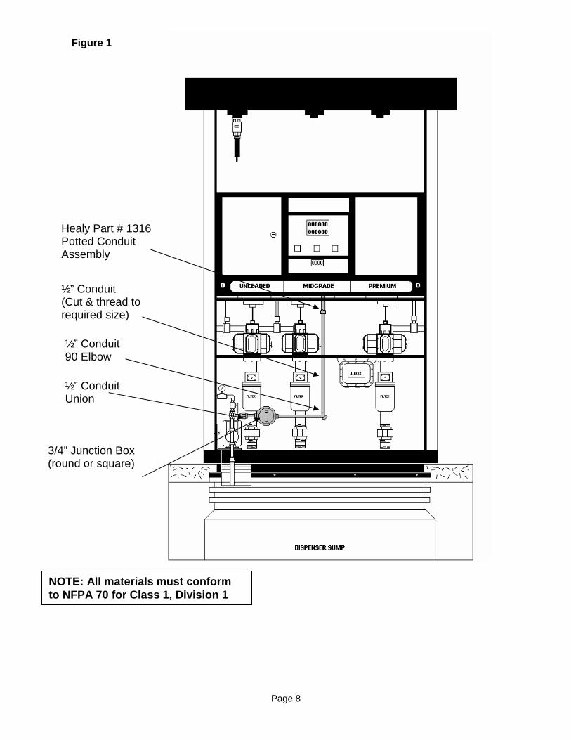
Figure 1
Healy Part # 1316 Potted Conduit Assembly
½” Conduit (Cut & thread to required size)
½” Conduit Union
½” Conduit 90 Elbow
3/4” Junction Box (round or square)
NOTE: All materials must conform to NFPA 70 for Class 1, Division 1
Page 8
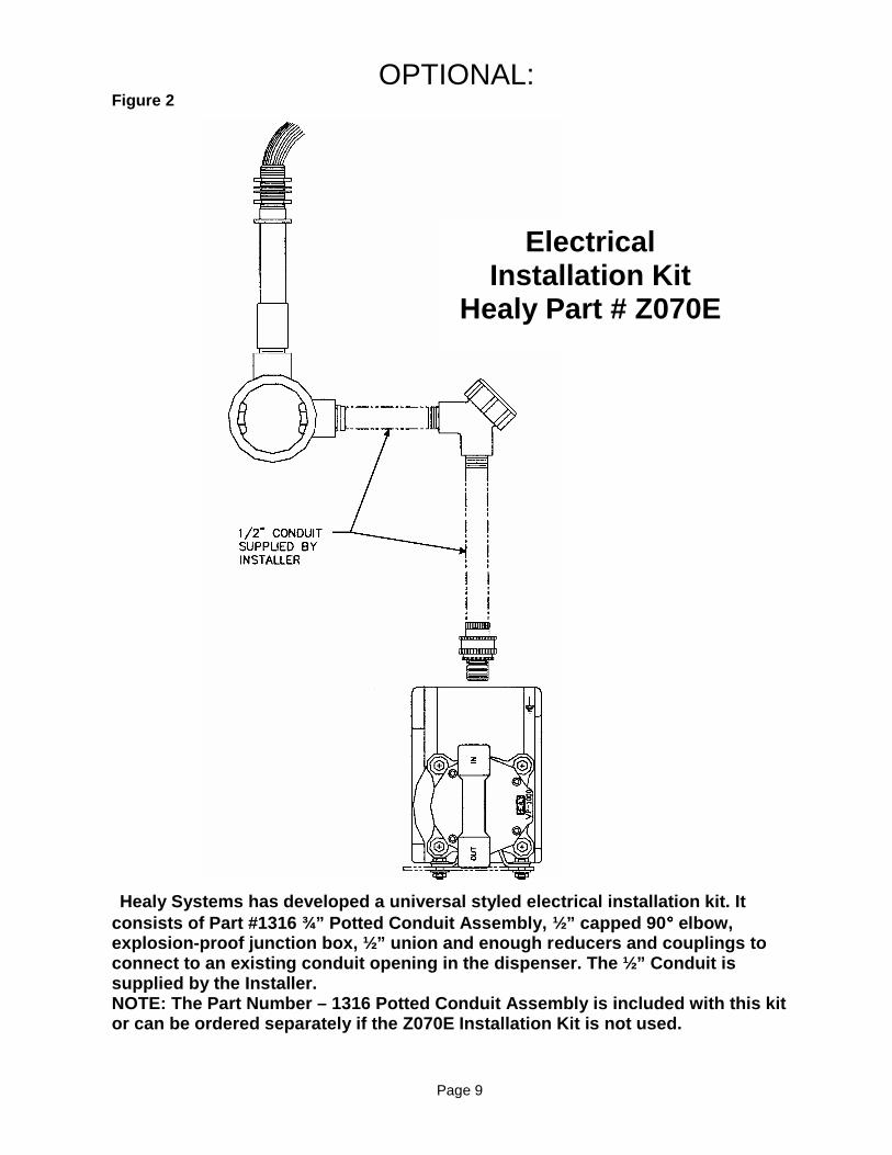
OPTIONAL: Figure 2
Healy Systems has developed a universal styled elec trical installation kit. It consists of Part #1316 ¾” Potted Conduit Assembly, ½” capped 90 °°°° elbow, explosion-proof junction box, ½” union and enough r educers and couplings to connect to an existing conduit opening in the dispe nser. The ½” Conduit is supplied by the Installer. NOTE: The Part Number – 1316 Potted Conduit Assembl y is included with this kit or can be ordered separately if the Z070E Installat ion Kit is not used.
Electrical Installation Kit
Healy Part # Z070E
Page 9

TYPICAL INSTALLATION OF PART #1316 POTTED CONDUIT A SSEMBLY
TYPICAL INSTALLATION OF PART #1346 POTTED CONDUIT A SSEMBLY
FOR USE ON DISPENSERS WITH CONDUIT OPENINGS ON THE SIDE OF THE ELECTRONIC HEAD ASSEMBLY
Page 10
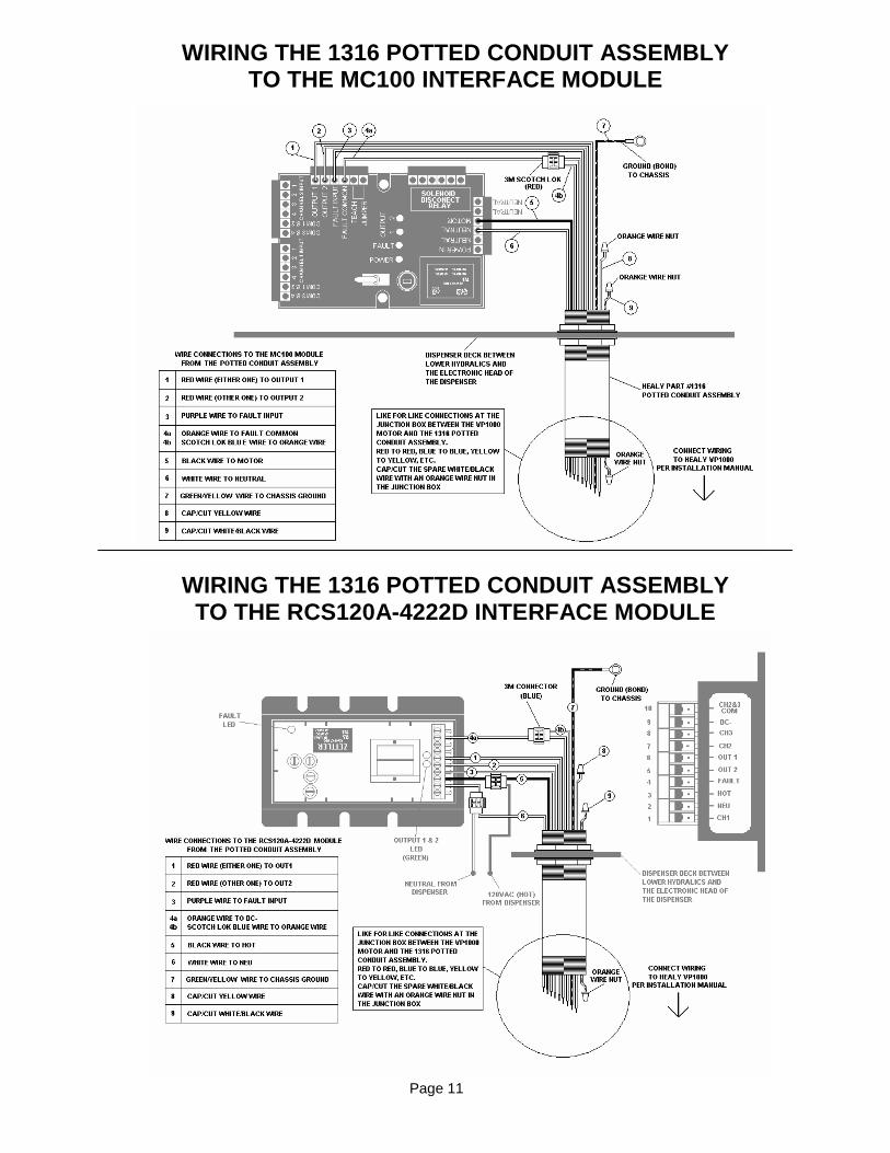
WIRING THE 1316 POTTED CONDUIT ASSEMBLY TO THE MC100 INTERFACE MODULE
WIRING THE 1316 POTTED CONDUIT ASSEMBLY TO THE RCS120A-4222D INTERFACE MODULE
Page 11

WIRING INSTRUCTIONS FOR 1360A INTERFACE MODULE/CABL E ASSEMBLY FOR A BLENDING OR NON-BLENDING DISPENSER UTILIZING EITHER VDC OR VAC SOLENOIDS This document is a supplement to and not a replacem ent of the HEALY SYSTEMS VAPOR RECOVERY MANUAL FOR GASOLINE REFUELING FACILITIES when using the Healy 1360A Module/Cable Assembly to interface the solenoid control board to the MC100 D ispenser Interface Module. All work is to be performed in a safe manner. All dispenser power is OFF. NOTE: The 1360 Wiring Kit is pre wired to the MC100 Interface Module. STEP 1. The module is mounted in the safe zone of the dispenser. The MC100 Interface Module can receive up to 4 individual AC or DC solenoid valve voltage inputs from each side of the dispenser. Working on one side of the dispenser at a time and starting on the “A” side, locate the solenoid valves slow flow hot wire (AC) or the pulsed wire (DC). With the 12’ length of brown wire, cut an appropriate length (roughly 3’) of wire and attach to the CHANNEL 1 INPUT Terminal #1 of the module. With a 3M Scotchlok, attach the other end (piggy-back) to the first solenoid valve slow flow hot (AC) wire or the pulsed (DC) wire. Repeat this process for the second solenoid valve slow flow hot (AC) wire or pulsed (DC) wire to the CHANNEL 1 INPUT to Terminal #2. Repeat this process for the third solenoid valve (if a third solenoid valve is present) slow flow hot (AC) wire or pulsed (DC) wire to the CHANNEL 1 INPUT Terminal #3. Repeat this process for the forth solenoid valve (if a forth solenoid valve is present) slow flow hot (AC) wire or pulsed (DC) wire to the CHANNEL 1 INPUT Terminal #4. Once the “A” side of the dispenser is wired, move to the opposite or “B” side of the dispenser and repeat the process above utilizing the 12” of blue wire provided from each solenoid valve slow flow (AC) or pulsed (DC) wire to the CHANNEL 2 INPUT starting with Terminal #1. STEP 2. Locate all the neutral (AC) or common (DC) wires from the solenoid valves. Half way between each solenoid valve and the connector to the dispenser control board cut the neutral (AC) or common (DC) wires. With a red wire-nut, connect all the neutral (AC) or common (DC) wires from the solenoid valves to the white/red wire from Module’s NO1 Terminal #1 NOTE: This jumper wire is also connected to the COM 1&2 and COM 3&4 for both the CHANNEL 1 INPUT and CHANNEL 2 INPUT of the module. With a red wire-nut, connect all the neutral (AC) or common (DC) wires from the solenoid valve drive board to the white/red wire from the Module’s COM1 Terminal #6. NOTE: Not all DC common wires from separate sides of the dispenser solenoid valves are common or connected together in the dispenser electronics. If the DC solenoid valves have different commons from one side of the dispenser to the other, contact the Healy Technical Services Department @ (603) 882-2472 for the appropriate wire changes. STEP 3. Select a suitable set of 115 VAC power wires, usually found near the “line” filter or in a spare accessory plug on the main power harness. Connect the white and black twisted wire pair from the “POWER IN” and “NEUTRAL” connections on the terminal block at one end of the Interface Module to the appropriate color “line” wiring. NOTE: a twisted pair of black and white wires has been supplied and factory wired to the “POWER IN” and “NEUTRAL” terminal block on the Interface Module. See the 1316 Potted Conduit Assembly wiring diagram for connections to the MC100 Interface Module.
Leave these instructions with the manual mentioned above.
Wiring instructions for 1360A 04/09/03 Page 12
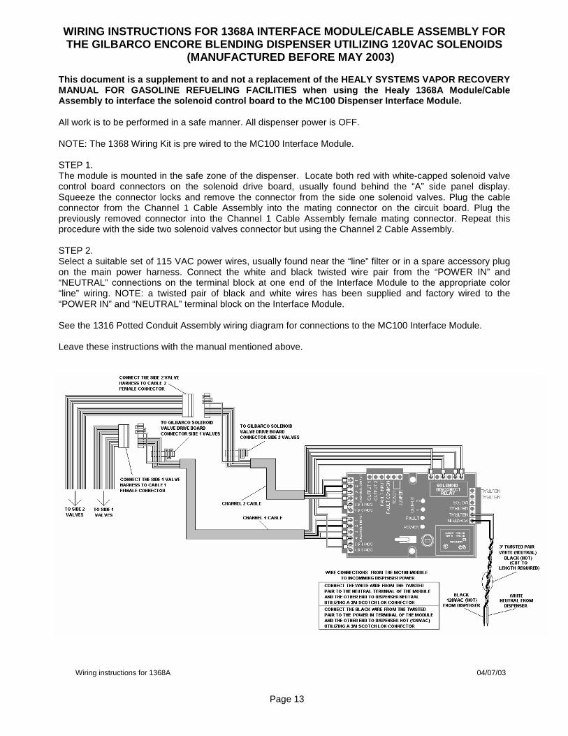
WIRING INSTRUCTIONS FOR 1368A INTERFACE MODULE/CABL E ASSEMBLY FOR THE GILBARCO ENCORE BLENDING DISPENSER UTILIZING 12 0VAC SOLENOIDS
(MANUFACTURED BEFORE MAY 2003) This document is a supplement to and not a replacem ent of the HEALY SYSTEMS VAPOR RECOVERY MANUAL FOR GASOLINE REFUELING FACILITIES when using the Healy 1368A Module/Cable Assembly to interface the solenoid control board to the MC100 Dispenser Interface Module. All work is to be performed in a safe manner. All dispenser power is OFF. NOTE: The 1368 Wiring Kit is pre wired to the MC100 Interface Module. STEP 1. The module is mounted in the safe zone of the dispenser. Locate both red with white-capped solenoid valve control board connectors on the solenoid drive board, usually found behind the “A” side panel display. Squeeze the connector locks and remove the connector from the side one solenoid valves. Plug the cable connector from the Channel 1 Cable Assembly into the mating connector on the circuit board. Plug the previously removed connector into the Channel 1 Cable Assembly female mating connector. Repeat this procedure with the side two solenoid valves connector but using the Channel 2 Cable Assembly. STEP 2. Select a suitable set of 115 VAC power wires, usually found near the “line” filter or in a spare accessory plug on the main power harness. Connect the white and black twisted wire pair from the “POWER IN” and “NEUTRAL” connections on the terminal block at one end of the Interface Module to the appropriate color “line” wiring. NOTE: a twisted pair of black and white wires has been supplied and factory wired to the “POWER IN” and “NEUTRAL” terminal block on the Interface Module. See the 1316 Potted Conduit Assembly wiring diagram for connections to the MC100 Interface Module. Leave these instructions with the manual mentioned above.
Wiring instructions for 1368A 04/07/03
Page 13

WIRING INSTRUCTIONS FOR 1369A INTERFACE MODULE/CABL E ASSEMBLY FOR THE GILBARCO ENCORE 300 NON-BLENDING DISPENSER UTILIZIN G 120VAC SOLENOIDS
(MANUFACTURED BEFORE MAY 2003) This document is a supplement to and not a replacem ent of the HEALY SYSTEMS VAPOR RECOVERY MANUAL FOR GASOLINE REFUELING FACILITIES when using the Healy 1369A Module/Cable Assembly to interface the solenoid control board to the RCS1 20A-4222D Dispenser Interface Module. All work is to be performed in a safe manner. All dispenser power is OFF. NOTE: The 1369 Wiring Kit is pre wired to the RCS120A-4222D Interface Module. STEP 1. The module is mounted in the safe zone of the dispenser. Locate all three solenoid valve control board connectors on the solenoid drive board, usually found behind the “A” side panel display. Starting from left to right, and doing one solenoid valve connector at a time, Squeeze the connector locks and remove the solenoid valve connector from the solenoid valve drive board. Plug the harness male connector into the mating connector on the solenoid valve drive board. Plug the previously removed solenoid valve connector into the cable female mating connector. Repeat this procedure with the two other solenoid valves connectors one at a time. STEP 2. Select a suitable set of 115 VAC power wires, usually found near the “line” filter or in a spare accessory plug on the main power harness. Connect the white and black twisted wire pair from the “POWER IN” and “NEUTRAL” connections on the terminal block at one end of the Interface Module to the appropriate color “line” wiring. NOTE: a twisted pair of black and white wires has been supplied and factory wired to the “POWER IN” and “NEUTRAL” terminal block on the Interface Module. See the 1316 Potted Conduit Assembly wiring diagram for connections to the RCS120A-4222D Interface Module. Leave these instructions with the manual mentioned above.
Wiring instructions for 1369A 04/08/03
Page 14
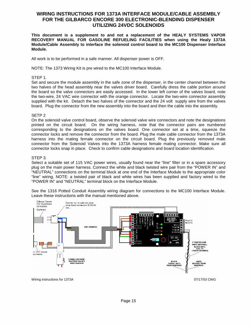
WIRING INSTRUCTIONS FOR 1373A INTERFACE MODULE/CABL E ASSEMBLY FOR THE GILBARCO ENCORE 300 ELECTRONIC-BLENDING DIS PENSER
UTILIZING 24VDC SOLENOIDS This document is a supplement to and not a replacem ent of the HEALY SYSTEMS VAPOR RECOVERY MANUAL FOR GASOLINE REFUELING FACILITIES w hen using the Healy 1373A Module/Cable Assembly to interface the solenoid con trol board to the MC100 Dispenser Interface Module. All work is to be performed in a safe manner. All dispenser power is OFF. NOTE: The 1373 Wiring Kit is pre wired to the MC100 Interface Module. STEP 1. Set and secure the module assembly in the safe zone of the dispenser, in the center channel between the two halves of the head assembly near the valves driver board. Carefully dress the cable portion around the board so the valve connectors are easily accessed. In the lower left corner of the valves board, note the two-wire, 24 VAC wire connector with the orange connector. Locate the two-wire connector assembly supplied with the kit. Detach the two halves of the connector and the 24 volt supply wire from the valves board. Plug the connector from the new assembly into the board and then the cable into the assembly. SETP 2 On the solenoid valve control board, observe the solenoid valve wire connectors and note the designations printed on the circuit board. On the wiring harness, note that the connector pairs are numbered corresponding to the designations on the valves board. One connector set at a time, squeeze the connector locks and remove the connector from the board. Plug the male cable connector from the 1373A harness into the mating female connector on the circuit board. Plug the previously removed male connector from the Solenoid Valves into the 1373A harness female mating connector. Make sure all connector locks snap in place. Check to confirm cable designations and board location identification. STEP 3. Select a suitable set of 115 VAC power wires, usually found near the “line” filter or in a spare accessory plug on the main power harness. Connect the white and black twisted wire pair from the “POWER IN” and “NEUTRAL” connections on the terminal block at one end of the Interface Module to the appropriate color “line” wiring. NOTE: a twisted pair of black and white wires has been supplied and factory wired to the “POWER IN” and “NEUTRAL” terminal block on the Interface Module. See the 1316 Potted Conduit Assembly wiring diagram for connections to the MC100 Interface Module. Leave these instructions with the manual mentioned above.
Wiring instructions for 1373A 07/17/03 CWG
Page 15
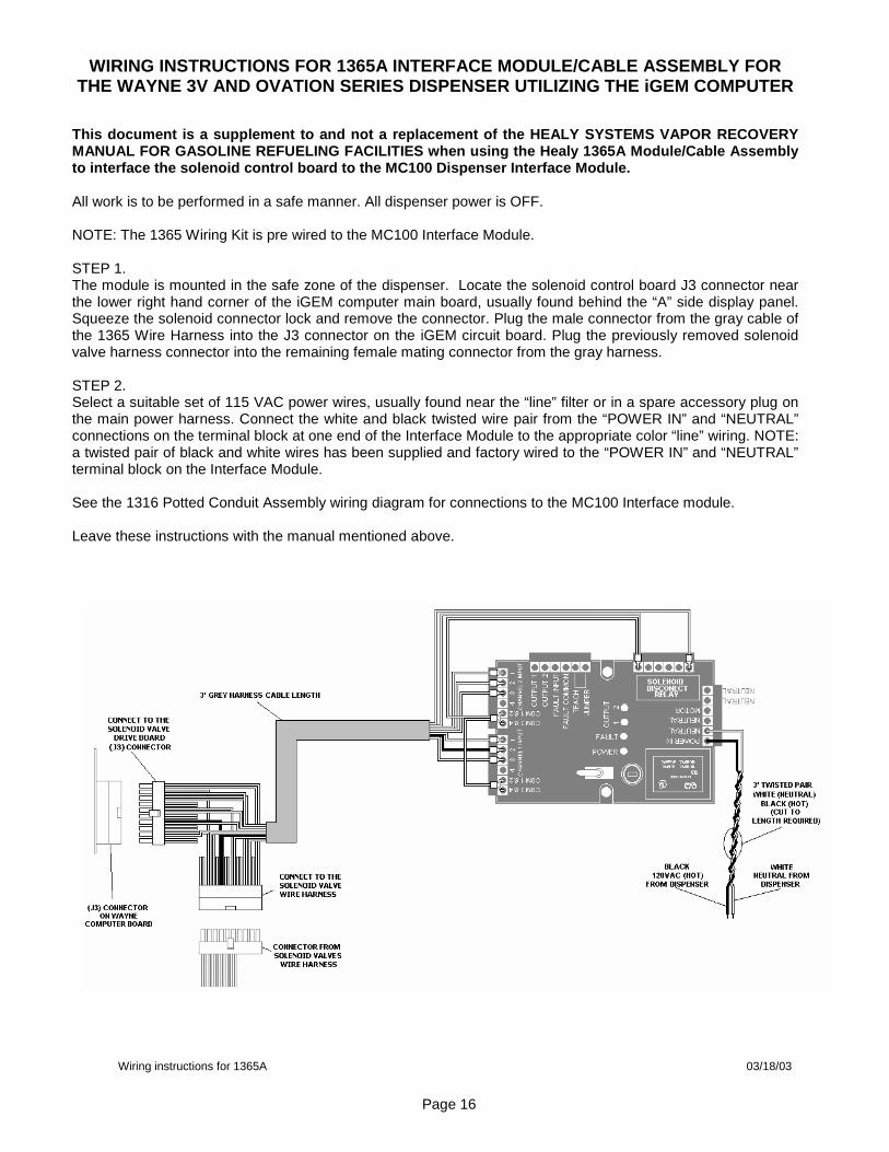
WIRING INSTRUCTIONS FOR 1365A INTERFACE MODULE/CABL E ASSEMBLY FOR
THE WAYNE 3V AND OVATION SERIES DISPENSER UTILIZING THE iGEM COMPUTER
This document is a supplement to and not a replacem ent of the HEALY SYSTEMS VAPOR RECOVERY MANUAL FOR GASOLINE REFUELING FACILITIES when using the Healy 1365A Module/Cable Assembly to interface the solenoid control board to the MC10 0 Dispenser Interface Module. All work is to be performed in a safe manner. All dispenser power is OFF. NOTE: The 1365 Wiring Kit is pre wired to the MC100 Interface Module. STEP 1. The module is mounted in the safe zone of the dispenser. Locate the solenoid control board J3 connector near the lower right hand corner of the iGEM computer main board, usually found behind the “A” side display panel. Squeeze the solenoid connector lock and remove the connector. Plug the male connector from the gray cable of the 1365 Wire Harness into the J3 connector on the iGEM circuit board. Plug the previously removed solenoid valve harness connector into the remaining female mating connector from the gray harness. STEP 2. Select a suitable set of 115 VAC power wires, usually found near the “line” filter or in a spare accessory plug on the main power harness. Connect the white and black twisted wire pair from the “POWER IN” and “NEUTRAL” connections on the terminal block at one end of the Interface Module to the appropriate color “line” wiring. NOTE: a twisted pair of black and white wires has been supplied and factory wired to the “POWER IN” and “NEUTRAL” terminal block on the Interface Module. See the 1316 Potted Conduit Assembly wiring diagram for connections to the MC100 Interface module. Leave these instructions with the manual mentioned above.
Wiring instructions for 1365A 03/18/03
Page 16

WIRING INSTRUCTIONS FOR 1363A INTERFACE MODULE/CABL E ASSEMBLY FOR THE WAYNE 1VISTA AND 2VISTA SERIES ELECTRONIC-B LENDING
DISPENSER UTILIZING 24VDC SOLENOIDS This document is a supplement to and not a replacem ent of the HEALY SYSTEMS VAPOR RECOVERY MANUAL FOR GASOLINE REFUELING FACILITIES w hen using the Healy 1363A Module/Cable Assembly to interface the solenoid con trol board to the MC100 Dispenser Interface Module. All work is to be performed in a safe manner. All dispenser power is OFF. NOTE: The 1363 Wiring Kit is pre wired to the MC100 Interface Module. STEP 1. The module is mounted in the safe zone of the dispenser. Locate the J3 solenoid valve control board connector near the center of the solenoid drive board, usually found behind the “A” side panel display. Squeeze the connector locks and remove the connector. Plug the Male cable connector from the 1363A harness into the mating Female connector on the circuit board. Plug the previously removed Male connector from the Solenoid Valves into the 1363A harness female mating connector. Make sure all connector locks snap in place. STEP 2. Select a suitable set of 115 VAC power wires, usually found near the “line” filter or in a spare accessory plug on the main power harness. Connect the white and black twisted wire pair from the “POWER IN” and “NEUTRAL” connections on the terminal block at one end of the Interface Module to the appropriate color “line” wiring. NOTE: a twisted pair of black and white wires has been supplied and factory wired to the “POWER IN” and “NEUTRAL” terminal block on the Interface Module. See the 1316 Potted Conduit Assembly wiring diagram for connections to the MC100 Interface Module. Leave these instructions with the manual mentioned above.
Page 17
Wiring instructions for 1363A 04/07/03
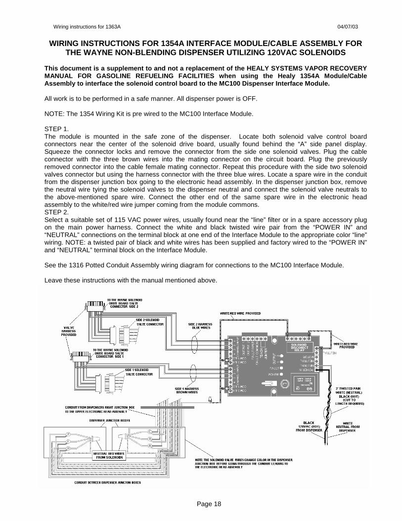
WIRING INSTRUCTIONS FOR 1354A INTERFACE MODULE/CABL E ASSEMBLY FOR
THE WAYNE NON-BLENDING DISPENSER UTILIZING 120VAC S OLENOIDS This document is a supplement to and not a replacem ent of the HEALY SYSTEMS VAPOR RECOVERY MANUAL FOR GASOLINE REFUELING FACILITIES when using the Healy 1354A Module/Cable Assembly to interface the solenoid control board to the MC100 Dispenser Interface Module. All work is to be performed in a safe manner. All dispenser power is OFF. NOTE: The 1354 Wiring Kit is pre wired to the MC100 Interface Module. STEP 1. The module is mounted in the safe zone of the dispenser. Locate both solenoid valve control board connectors near the center of the solenoid drive board, usually found behind the “A” side panel display. Squeeze the connector locks and remove the connector from the side one solenoid valves. Plug the cable connector with the three brown wires into the mating connector on the circuit board. Plug the previously removed connector into the cable female mating connector. Repeat this procedure with the side two solenoid valves connector but using the harness connector with the three blue wires. Locate a spare wire in the conduit from the dispenser junction box going to the electronic head assembly. In the dispenser junction box, remove the neutral wire tying the solenoid valves to the dispenser neutral and connect the solenoid valve neutrals to the above-mentioned spare wire. Connect the other end of the same spare wire in the electronic head assembly to the white/red wire jumper coming from the module commons. STEP 2. Select a suitable set of 115 VAC power wires, usually found near the “line” filter or in a spare accessory plug on the main power harness. Connect the white and black twisted wire pair from the “POWER IN” and “NEUTRAL” connections on the terminal block at one end of the Interface Module to the appropriate color “line” wiring. NOTE: a twisted pair of black and white wires has been supplied and factory wired to the “POWER IN” and “NEUTRAL” terminal block on the Interface Module. See the 1316 Potted Conduit Assembly wiring diagram for connections to the MC100 Interface Module. Leave these instructions with the manual mentioned above.
Page 18

Wiring instructions for 1354A 04/07/03
WIRING INSTRUCTIONS FOR 1362A INTERFACE MODULE/CABL E ASSEMBLY FOR THE TOKHEIM PREMIER BLENDING DISPENSER
This document is a supplement to and not a replacem ent of the HEALY SYSTEMS VAPOR RECOVERY MANUAL FOR GASOLINE REFUELING FACILITIES w hen using the Healy 1362A Interface Module/Cable Assembly to interface the so lenoid control board to the MC100 Dispenser Interface Module. All work is to be performed in a safe manner. All dispenser power is OFF. NOTE: The 1362 Wiring Kit is pre wired to the MC100 Interface Module. STEP 1. The module is mounted in the safe zone of the dispenser. Locate the solenoid control board in the card-cage of the electronic head assembly, usually found behind the “A” side display panel. Note: Perform the following one plug at a time to avoid switching valve activation sequence. Starting at the top male solenoid valve wire connector, marked with the number “4”, squeeze the connector lock and remove the connector. Immediately plug that into the top connector on the interface harness. Take the corresponding mating plug on the harness and plug into the top connector on the circuit board that contained the original plug. Make sure the locks snap in place. Continue this same procedure with the remaining seven connectors one at a time. STEP 2. Select a suitable set of 115 VAC power wires, usually found near the “line” filter or in a spare accessory plug on the main power harness. Connect the white and black twisted wire pair from the “POWER IN” and “NEUTRAL” connections on the terminal block at one end of the Interface Module to the appropriate color “line” wiring. NOTE: a twisted pair of black and white wires has been supplied and factory wired to the “POWER IN” and “NEUTRAL” terminal block on the Interface Module. See the 1316 Potted Conduit Assembly wiring diagram for connections to the MC100 Interface Module. Leave these instructions with the manual mentioned above.
24VDC Solenoid Valves
Factory Solenoid Valve connection is removed from the Relay Control Board and connected to Healy Wiring Harness.
Page 19

Wiring instructions for 1362A 03/18/03
WIRING INSTRUCTIONS FOR 1372A INTERFACE MODULE/CABL E ASSEMBLY FOR THE TOKHEIM BLENDING DISPENSER UTILIZING BOTH 24VDC AND 120VAC
SOLENOIDS This document is a supplement to and not a replacem ent of the HEALY SYSTEMS VAPOR RECOVERY MANUAL FOR GASOLINE REFUELING FACILITIES when using the Healy 1372A Module/Cable Assembly to interface the solenoid control board to the MC100 Dispenser Interface Module. All work is to be performed in a safe manner. All dispenser power is OFF. NOTE: The 1372 Wiring Kit is pre wired to the MC100 Interface Module. STEP 1. 24VDC Solenoid Valves The module is mounted in the safe zone of the dispenser. Locate the solenoid control board in the card-cage of the electronic head assembly, usually found behind the “A” side display panel. Note: Perform the following one plug at a time to avoid switching valve activation sequence. Starting at the top male solenoid valve wire connector, marked with the number “4”, squeeze the connector lock and remove the connector. Immediately plug that into the top connector on the interface harness. Take the corresponding mating plug on the harness and plug into the top connector on the circuit board that contained the original plug. Make sure the locks snap in place. Continue this same procedure with the remaining seven connectors one at a time. STEP 2. 120VAC Solenoid Valves Locate the two yellow wires coming from channel 1 input terminals #3 and #4. With a 3M Scotch lok, connect (piggy-back) one of the yellow wires to one of the “A” side solenoid valve yellow hot wire that powers the slow flow portion of the valve. With the remaining yellow wire from the channel 1 input, 3M Scotch lok, connect (piggy-back) the other yellow wire to the other “A” side solenoid valve yellow hot wire that powers the slow flow portion of the valve. Repeat this process with the two yellow wires from the channel 2 input connecting to the “B” side yellow slow flow hot wires. Locate the four red neutral wires from the solenoid valves. Half way between each solenoid valve and the connector to the dispenser control board cut the four red neutral wires. With a red wire-nut, connect the four red wires from the solenoid valves to the white/red wire from Module’s COM1 Terminal #6. With a red wire-nut, connect the four red wires from the solenoid valve drive board to the white/red wire from the Module’s NO1 Terminal #1. STEP 3. Select a suitable set of 115 VAC power wires, usually found near the “line” filter or in a spare accessory plug on the main power harness. Connect the white and black twisted wire pair from the “POWER IN” and “NEUTRAL” connections on the terminal block at one end of the Interface Module to the appropriate color “line” wiring. NOTE: a twisted pair of black and white wires has been supplied and factory wired to the “POWER IN” and “NEUTRAL” terminal block on the Interface Module. See the 1316 Potted Conduit Assembly wiring diagram for connections to the MC100 Interface Module. Leave these instructions with the manual mentioned above.
Wiring instructions for 1372A 04/09/03 Page 20

ADJUSTING THE RCS120A-4222D INTERFACE MODULE
After installing the RCS120A-4222D Interface module, and the dispenser is ready to be tested, the VP1000 should come on at low speed when either side of the dispenser is activated and increase to high speed when both sides of the dispenser are activated. Although no adjustments should be necessary, occasionally a particular dispenser may require adjustment on the RCS120A-4222D Module for proper operation. On the top of the Module you will find four (4) pointed soft red covers. Under these covers are adjustment potentiometers. Cut about two-thirds through, without cutting if off completely, the top of only the adjustment potentiometer screw(s) needing adjustment. The two adjustment screws closest to the side of the module are for CH1 - 120VAC solenoid valves including Gilbarco optimized 120VAC valves NOTE: (Manufactured before May 2003). The two closest to the red LED light are not currently used. Pull back the cut red tip and use a small bladed jewelers screwdriver (smaller than 1/8” wide and 1” long) to make adjustments. Follow the chart below as to which pot needs adjusting. NOTE: Use caution; it is possible to adjust any of these to the point where the motor will run at high speed at all times even if the dispenser is not authorized.
120VAC ADJUSTMENT High Threshold Adjustment (High Speed) 120VAC Solenoid Valve (CH1) Turning Clockwise Increases Threshold Low Threshold Adjustment (Low Speed) 120VAC Solenoid Valve (CH1) Turning Clockwise Increases Threshold
Red LED Fault Light
AC Low Speed Current Threshold = .080A ± .05A
AC High Speed Current Threshold = .300A ± .05A
Page 21

HOW TO IDENTIFY HEALY DISPENSER INTERFACE MODULES
From the inception of the VP1000 Dispenser Mounted Vapor Recovery System, a dispenser interface has been required. The interface module has changed design configuration from time to time in order to meet the demands of the dispenser manufactures changes in electronic solenoid valves. Each design change can be a direct replacement for a previous version. The MC100 is an updated version of the module utilized for both a non-blending dispenser with 120VAC solenoids and most every electronic blending dispenser. All of the Healy Interface Modules have an identifying sticker with a part number listed. Below is a description of each of the module designs:
MC100 DVR120A-3896
RCS120A-4084 RCS120A-4222-D
Discontinued first voltage sensing Module design used with all non-blending dispensers utilizing 120VAC solenoid valves only. The three brown and three blue wires off the opposite side of the top of the module from the wire terminal strip location identify this module.
Recent version used with Gilbarco Encore and Eclipse NON- blending dispensers NOTE: (Manufactured before May 2003). This Module was shipped with the VP1000B Vacuum Pump Assembly. Works with Gilbarco optimized solenoid valves. Has a two second time delay for pulsing valves. The adjustment pots are all grouped together near the fault LED. Has two green signal indicator LED’s NOTE: Previous model (RCS120A-4222) HAS NO TIME DELAY
Discontinued version used with all electronic blending dispensers. This Module was shipped with the VP1000B Vacuum Pump Assembly. This Module was replaced by the RCS120A-4222D. The RCS120A-4222-D can be used as a direct replacement without wiring changes. The adjustment pots are separated, the two near the fault LED are for DC adjustments and the two near the terminal strip are for AC adjustments.
Updated version used with most all dispensers. This Module is shipped with the VP1000A, VP1000B and VP1000C Vacuum Pump Assembly. Works with both AC and DC current solenoid valves and can be used as a direct replacement for all previous version modules. The Module has four LED’s, a yellow power LED, two green signal indicator LED’s and a red fault LED. It has a reset switch and has a replaceable fuse.
Page 22
TROUBLESHOOTING GUIDE
Healy VP1000 Dispenser Mounted Vacuum Pump
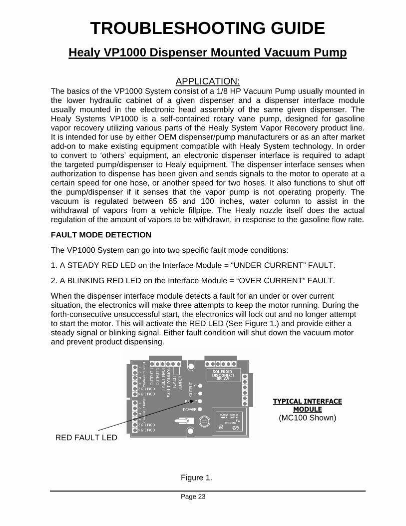
APPLICATION: The basics of the VP1000 System consist of a 1/8 HP Vacuum Pump usually mounted in the lower hydraulic cabinet of a given dispenser and a dispenser interface module usually mounted in the electronic head assembly of the same given dispenser. The Healy Systems VP1000 is a self-contained rotary vane pump, designed for gasoline vapor recovery utilizing various parts of the Healy System Vapor Recovery product line. It is intended for use by either OEM dispenser/pump manufacturers or as an after market add-on to make existing equipment compatible with Healy System technology. In order to convert to ‘others’ equipment, an electronic dispenser interface is required to adapt the targeted pump/dispenser to Healy equipment. The dispenser interface senses when authorization to dispense has been given and sends signals to the motor to operate at a certain speed for one hose, or another speed for two hoses. It also functions to shut off the pump/dispenser if it senses that the vapor pump is not operating properly. The vacuum is regulated between 65 and 100 inches, water column to assist in the withdrawal of vapors from a vehicle fillpipe. The Healy nozzle itself does the actual regulation of the amount of vapors to be withdrawn, in response to the gasoline flow rate.
FAULT MODE DETECTION
The VP1000 System can go into two specific fault mode conditions:
1. A STEADY RED LED on the Interface Module = “UNDER CURRENT” FAULT.
2. A BLINKING RED LED on the Interface Module = “OVER CURRENT” FAULT.
When the dispenser interface module detects a fault for an under or over current situation, the electronics will make three attempts to keep the motor running. During the forth-consecutive unsuccessful start, the electronics will lock out and no longer attempt to start the motor. This will activate the RED LED (See Figure 1.) and provide either a steady signal or blinking signal. Either fault condition will shut down the vacuum motor and prevent product dispensing.
RED FAULT LED
TYPICAL INTERFACE
MODULE
(MC100 Shown)
Figure 1.
Page 23

NOTE: The most common fault conditions are usually associated with a problem in the Vane and Rotor Cavity at the piping end of the VP1000 assembly. There are four, 5/32” Allen-head screws (See Item 1) that need to be removed in order to access the vanes and rotor. When removing the cover assembly, be careful not to damage the O-Ring seal (See Item 2) on the outside of the rotor cavity. Lubricate the O-Ring before re-assembly. WARNING: WHEN RE-ASSEMBLY, DO NOT LUBRICATE THE VANES AND ROTOR ASSEMBLY.
SYMPTOMS: “UNDER CURRENT” FAULT (STEADY RED LED)
A solid red LED on the interface module. This means the VP1000 Vacuum Pump has shut down and is preventing product dispensing due to an under current condition (very little or no load on the motor).
PROBLEMS: Possible causes for “UNDER CURRENT” FAULTS are as follows:
1) Vanes are stuck in the VP1000 rotor assembly.
Vanes stuck in rotor
(INCORRECT) Vanes thrown out
(CORRECT)
Page 24
2) Broken shaft key or damaged rotor assembly. 3) Significant leak in the dispensers interior vapor piping. A leak somewhere between
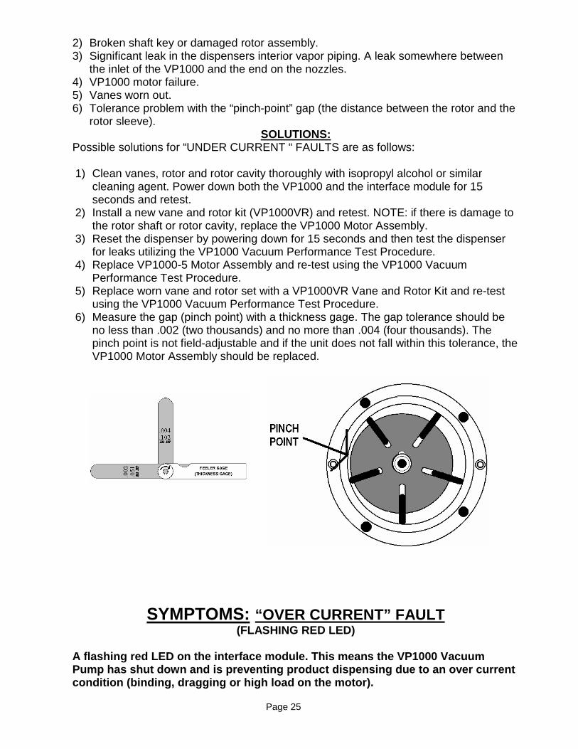
the inlet of the VP1000 and the end on the nozzles. 4) VP1000 motor failure. 5) Vanes worn out. 6) Tolerance problem with the “pinch-point” gap (the distance between the rotor and the
rotor sleeve). SOLUTIONS:
Possible solutions for “UNDER CURRENT “ FAULTS are as follows: 1) Clean vanes, rotor and rotor cavity thoroughly with isopropyl alcohol or similar
cleaning agent. Power down both the VP1000 and the interface module for 15 seconds and retest.
2) Install a new vane and rotor kit (VP1000VR) and retest. NOTE: if there is damage to the rotor shaft or rotor cavity, replace the VP1000 Motor Assembly.
3) Reset the dispenser by powering down for 15 seconds and then test the dispenser for leaks utilizing the VP1000 Vacuum Performance Test Procedure.
4) Replace VP1000-5 Motor Assembly and re-test using the VP1000 Vacuum Performance Test Procedure.
5) Replace worn vane and rotor set with a VP1000VR Vane and Rotor Kit and re-test using the VP1000 Vacuum Performance Test Procedure.
6) Measure the gap (pinch point) with a thickness gage. The gap tolerance should be no less than .002 (two thousands) and no more than .004 (four thousands). The pinch point is not field-adjustable and if the unit does not fall within this tolerance, the VP1000 Motor Assembly should be replaced.
SYMPTOMS: “OVER CURRENT” FAULT (FLASHING RED LED)
A flashing red LED on the interface module. This me ans the VP1000 Vacuum Pump has shut down and is preventing product dispen sing due to an over current condition (binding, dragging or high load on the mo tor).
Page 25
PROBLEMS: Possible causes for “OVER CURRENT” FAULTS are as follows: 1) Rotor binding from a foreign item(s) such as a broken vane, excessive pipe dope, or
something sucked in from the dispenser piping. 2) Damage to the rotor assembly or vanes. 3) Tolerance problem with the “pinch-point” gap (the distance between the rotor and the
rotor sleeve). 4) Traps in the dispenser vapor piping causing blockage.
SOLUTIONS: Possible solutions for “OVER CURRENT” FAULTS are as follows: 1) Remove any foreign items and clean vanes, rotor and rotor cavity thoroughly with
isopropyl alcohol. Power down both the VP1000 and the interface module for 15 seconds and retest using the VP1000 Vacuum Performance Test Procedure.
2) Install a new vane and rotor kit (VP1000VR) and retest using the VP1000 Vacuum Performance Test Procedure. NOTE: if there is damage to the rotor shaft or rotor cavity, replace the VP1000 motor assembly.
3) Measure the gap (pinch point) with a thickness gage. The gap tolerance should be no less than .002 (two thousands) and no more than .004 (four thousands). The pinch point is not field-adjustable and if the unit does not fall within this tolerance, the VP1000 Motor Assembly should be replaced.
4) Repair or replace the vapor piping to maintain proper slope to the VP1000 pump inlet or from the VP1000 pump outlet to the underground piping.
TROUBLESHOOTING THE MODULE To check for proper operation of the interface module, perform the tests below:
• Be sure the module has been wired per the instructions for the module. • With power to the dispenser, but not authorized, check for 120 VAC between the
black and white wires; 5 VDC between the orange and purple wires; no voltage between the orange and either red wire.
• With the dispenser powered and one side authorized, check for 2.5 VDC between the orange wire and either of the red wires. With both sides authorized, check for 2.5 VDC between the orange and each of the red wires.
• For DVR modules, check for 120 VAC to be present on one of the blue or brown wires when one side of the dispenser is authorized – then check for the 2.5 VDC as above. Check for 120 VAC to be present on both a brown wire and a blue wire when both sides are authorized – check again for the 2.5 VDC as above.
• For RCS modules on Gilbarco or Wayne, connect an AC ammeter in series between the Channel 1 wire and the Channel 1 terminal on the module – activate the dispenser, one side and look for a minimum of .08 amps AC (80 milliamps), with both sides, look for a minimum of .300 amps AC (300 milliamps). If the dispenser is an electronic blending unit, Connect a DC ammeter in series between the Channel 2-3 terminal and the Channel 2-3 wires – activate the dispenser, one side and look for .300 amps DC (300 milliamps) minimum and .700 amps DC (700 milliamps) with both sides activated. Check for the 2.5 VDC as above. See the specific module adjustments sheet for the details on how to make trim pot adjustments.
Page 26

VP1000VR VANE & ROTOR REPLACEMENT KIT
NOTE: DISCONNECT ALL POWER TO THIS EQUIPMENT AND CL OSE ALL VALVES IN THE
INCOMING PIPING BEFORE PROCEEDING
1. The installation/work area must be clean and well lighted. 2. Disconnect the vapor piping from the IN and OUT ports of the VP1000 cover assembly. 3. Remove the four Allen head screws and lock washers that secure the pump cover assembly to the
pump housing and remove the cover carefully. CAUTION: Use a spill cloth when removing the cover, as there may be some gasoline inside the pum p cavity. NOTE: There might be a .002 thick circular shim (silver in color) installed on the inside of the cover (See Figure 3). If there is, remove it and discard. SEE ADDITIONAL CAUTION NOTE REGARDING SEAL WASHER ON BACK.
4. Carefully turn the rotor assembly by hand until the shaft key notch is at the 12 o’clock position. (See Figure 1.)
5. Remove the rotor, vanes and shaft key from the pump housing. NOTE: Place your hand or a container under the rotor while removing.
6. Using a lint free cloth or rag moistened with rubbing alcohol, thoroughly clean the inside and rear of the pump cavity, rotor shaft, and the inside of the pump cover assembly. NOTE: Do not use any sharp objects that would scratch these surfaces .
7. Reposition the shaft (if necessary) so that the shaft key notch is in the 12 o’clock position and install the (white) shaft seal washer. Place the washer on the shaft and slide all the way down on top of the shaft seal. Make sure the washer is inside the shaft seal counter-bore and is not protruding above the rear pump housing. Install the new shaft key supplied in the kit onto the shaft.
8. Carefully install the new Carbon rotor onto the shaft and insert the new vanes into the rotor. NOTE: There should not be force required to slip th e rotor assembly on to the shaft or the vanes into the rotor. Rotor and vanes are reversibl e. Make sure that the rotor does not extend beyond the pump housing. After the new rotor is installed, measure the gap (pinch point) with a thickness gage (See Figure 4). The ga p tolerance should be no less than .002 (two thousands) and no more than .004 (four thousan ds). The pinch point is not field adjustable and if the unit does not fall within thi s tolerance, the VP1000 Motor Assembly should be replaced.
9. Lightly lubricate the O-Ring on the outside edge of the pump housing if reusing the existing one or, remove the existing O-RING and lubricate and install the new one. NOTE: Do not allow any grease or oil to get inside the pump housing.
10. Install the four Allen head screws and lock washers removed in step 3 and cross tighten. Re-connect the vapor piping to the IN and OUT ports of the pump cover assembly that was
removed in step 2. 11. Re-apply power and open incoming valves. Test for normal operation. (See VP1000 Vacuum
Performance Test Procedure).
SHAFT SEAL
WASHER Figure 1
Page 27

Figure 2 Figure 3 COVER WITHOUT SHIM INSTALLED COVER WITH SHIM IN STALLED
For further assistance call the Healy Systems Techn ical Service Department @ (603) 882-2472 - Monday through Friday - 8:00 a. m. to 5:00 p.m. E.S.T.
Please refer to the current California Air Resource s Board (CARB) Executive Orders:
G-70-70-183AA (VP1000 – 600 Series Nozzle) or G-70- 191AA (VP1000 – 600ORVR/800 Series Nozzle) for site required system compliance tests.
IMPORTANT CAUTION NOTE: A number of early versions of the VP1000 Vacuum Pum p assembly – green painted units only - contained bronze rotors with a seal assembly on the motor shaft. With the pump cover removed, inspect the rotor for a bevel around the shaft hole and/or a rubber seal inside the front shaft hole. These units also had a seal on the rear rotor shaft access, but more importantly, there was a rubber seal ring and seal washer mounted on the mot or shaft up against the rear shaft seal, inside the pump cavity . This washer and rubber seal must be removed before installing the new rotor, shaft seal washer and vanes. FAILURE TO REMOVE THIS WASHER WILL RESULT IN A ST ALLED ROTOR CAUSING A BLINKING FAULT LED ON THE INTERFACE MODULE. It also may damage the
shaft seal and allow leakage of liquid or vapor .
.002 SHIM
Figure 4
Page 28
VP1000 VACUUM PERFORMANCE TEST PROCEDURE
Note: Performance Testing should be conducted after any maintenance work to the VP1000 is completed.
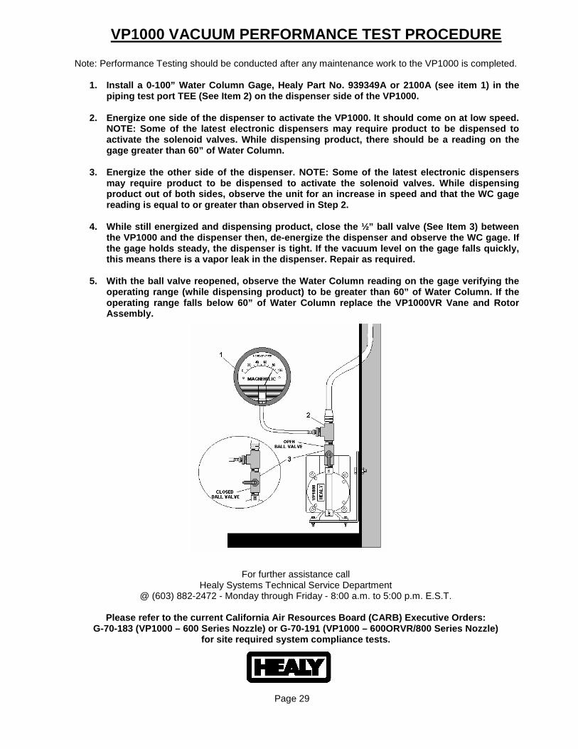
1. Install a 0-100” Water Column Gage, Healy Part N o. 939349A or 2100A (see item 1) in the piping test port TEE (See Item 2) on the dispenser side of the VP1000.
2. Energize one side of the dispenser to activate t he VP1000. It should come on at low speed.
NOTE: Some of the latest electronic dispensers may require product to be dispensed to activate the solenoid valves. While dispensing product, there should be a reading on the gage greater than 60” of Water Column.
3. Energize the other side of the dispenser. NOTE: Some of the latest electronic dispensers
may require product to be dispensed to activate the solenoid valves. While dispensing product out of both sides, observe the unit for an increase in speed and that the WC gage reading is equal to or greater than observed in Ste p 2.
4. While still energized and dispensing product, cl ose the ½” ball valve (See Item 3) between
the VP1000 and the dispenser then, de-energize the dispenser and observe the WC gage. If the gage holds steady, the dispenser is tight. If t he vacuum level on the gage falls quickly, this means there is a vapor leak in the dispenser. Repair as required.
5. With the ball valve reopened, observe the Water Column reading on the gage verifying the
operating range (while dispensing product) to be gr eater than 60” of Water Column. If the operating range falls below 60” of Water Column rep lace the VP1000VR Vane and Rotor Assembly.
For further assistance call
Healy Systems Technical Service Department @ (603) 882-2472 - Monday through Friday - 8:00 a.m. to 5:00 p.m. E.S.T.
Please refer to the current California Air Resource s Board (CARB) Executive Orders:
G-70-183 (VP1000 – 600 Series Nozzle) or G-70-191 ( VP1000 – 600ORVR/800 Series Nozzle) for site required system compliance tests.
Page 29
FIELD REPAIR INSTRUCTIONS 600 / 800 SERIES NOZZLES
IMPORTANT NOTE:
The Healy Models 600 / 800 series Vapor Recovery Nozzles should be serviced by Healy qualified repair personnel only. Interior parts are not field replaceable. Functional test must be performed before returning nozzles to normal use. Only exterior parts can be replaced in the field.
VaporGuard Replacement: Part #6118 (Standard 600 Nozzle Only) To replace the VaporGuard, (See Figure 2. Item #10) unscrew the VaporGuard Clamp (See Figure 2. Item #9) and remove. (If Oetiker-type clamp, slip a small screwdriver under the overlap tab on the bottom and pry up past the locking tab.) Rotate the VaporGuard and pull to separate the VaporGuard from the nozzle. To install, simply slide the new VaporGuard over the spout with a twisting/pushing motion. Install a VaporGuard Clamp (Part #6119) and tighten securely, being sure to align the “HEALY” line on the VaporGuard with the top center of the nozzle.
Helpful Hint: Heating in hot water will soften the VaporGuard making it easier to install.
Mini-Boot Replacement: Part #6395A (800 Series Nozzle Only) To replace the Mini-Boot, (See Figure 1. Item #1) unscrew the Mini-Boot Clamp (See Figure 1. Item #2) and remove. Rotate the Mini-Boot and pull to separate the Mini-Boot from the nozzle. To install, simply slide the new Mini-Boot over the spout with a twisting/pushing motion. Install a Mini-Boot Clamp (Part #640956) and tighten securely, being sure to align the “HEALY” line on the Mini-Boot with the top center of the nozzle. Helpful Hint: Heating in hot water will soften the Mini-Boot making it easier to install.
Spout Replacement: Part #6204-G4 (Standard 600 Nozzle Only) Part #8014 (800 Series ORVR Nozzle Only)
REMOVE THE OLD SPOUT: Use a Phillips Screwdriver to remove the #8 panhead Spout Screw & O-Ring, Part #6102A (See Figure 2. Item #13), holding the spout in place. With the screw removed, separate the nozzle and the spout. Three o-rings should come out with the spout. If not, check to see if the o-rings are stuck inside the nozzle. There is an additional o-ring inside the nozzle in a separate groove, - this should be left in place.
INSTALL THE NEW SPOUT: Install new, unused o-rings on the replacement spout. (NOTE: new o-rings are provided with the Part #6206-G4 & #8014 Replacement Spout, if new o-rings are needed, Order Part #6206-OR Spout O-Ring Kit). Lubricate the o-rings with oil. Carefully insert the spout into the nozzle, lightly pushing together until the spout aligns itself and resistance is felt. Using a twisting motion and light pressure, slide the pieces together, seating the o-rings and aligning the screw threads in the spout housing with the hole in the nozzle casting. Install the new #8 panhead Spout Screw & O-Ring, (provided with the Part #6206-G4 & #8014 Replacement Spout), and tighten securely to 12 inch pounds.
Page 30
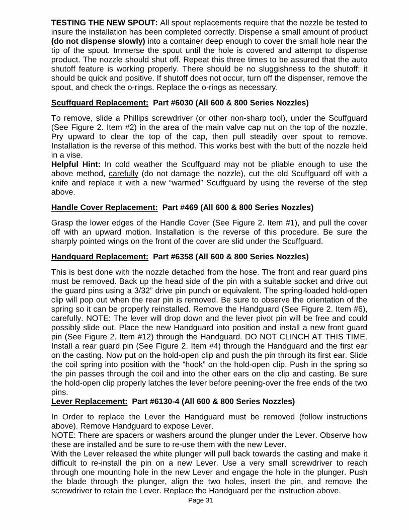
TESTING THE NEW SPOUT: All spout replacements require that the nozzle be tested to insure the installation has been completed correctly. Dispense a small amount of product (do not dispense slowly) into a container deep enough to cover the small hole near the tip of the spout. Immerse the spout until the hole is covered and attempt to dispense product. The nozzle should shut off. Repeat this three times to be assured that the auto shutoff feature is working properly. There should be no sluggishness to the shutoff; it should be quick and positive. If shutoff does not occur, turn off the dispenser, remove the spout, and check the o-rings. Replace the o-rings as necessary.
Scuffguard Replacement: Part #6030 (All 600 & 800 Series Nozzles)
To remove, slide a Phillips screwdriver (or other non-sharp tool), under the Scuffguard (See Figure 2. Item #2) in the area of the main valve cap nut on the top of the nozzle. Pry upward to clear the top of the cap, then pull steadily over spout to remove. Installation is the reverse of this method. This works best with the butt of the nozzle held in a vise. Helpful Hint: In cold weather the Scuffguard may not be pliable enough to use the above method, carefully (do not damage the nozzle), cut the old Scuffguard off with a knife and replace it with a new “warmed” Scuffguard by using the reverse of the step above.
Handle Cover Replacement: Part #469 (All 600 & 800 Series Nozzles)
Grasp the lower edges of the Handle Cover (See Figure 2. Item #1), and pull the cover off with an upward motion. Installation is the reverse of this procedure. Be sure the sharply pointed wings on the front of the cover are slid under the Scuffguard.
Handguard Replacement: Part #6358 (All 600 & 800 Series Nozzles)
This is best done with the nozzle detached from the hose. The front and rear guard pins must be removed. Back up the head side of the pin with a suitable socket and drive out the guard pins using a 3/32” drive pin punch or equivalent. The spring-loaded hold-open clip will pop out when the rear pin is removed. Be sure to observe the orientation of the spring so it can be properly reinstalled. Remove the Handguard (See Figure 2. Item #6), carefully. NOTE: The lever will drop down and the lever pivot pin will be free and could possibly slide out. Place the new Handguard into position and install a new front guard pin (See Figure 2. Item #12) through the Handguard. DO NOT CLINCH AT THIS TIME. Install a rear guard pin (See Figure 2. Item #4) through the Handguard and the first ear on the casting. Now put on the hold-open clip and push the pin through its first ear. Slide the coil spring into position with the “hook” on the hold-open clip. Push in the spring so the pin passes through the coil and into the other ears on the clip and casting. Be sure the hold-open clip properly latches the lever before peening-over the free ends of the two pins. Lever Replacement: Part #6130-4 (All 600 & 800 Series Nozzles)
In Order to replace the Lever the Handguard must be removed (follow instructions above). Remove Handguard to expose Lever. NOTE: There are spacers or washers around the plunger under the Lever. Observe how these are installed and be sure to re-use them with the new Lever. With the Lever released the white plunger will pull back towards the casting and make it difficult to re-install the pin on a new Lever. Use a very small screwdriver to reach through one mounting hole in the new Lever and engage the hole in the plunger. Push the blade through the plunger, align the two holes, insert the pin, and remove the screwdriver to retain the Lever. Replace the Handguard per the instruction above. Page 31
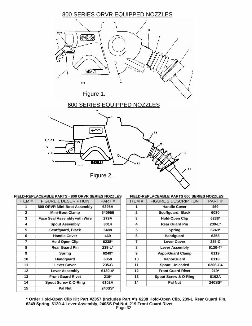
800 SERIES ORVR EQUIPPED NOZZLES
FIELD-REPLACEABLE PARTS - 800 ORVR SERIES NOZZLES FIELD-REPLACEABLE PARTS 600 SERIES NOZZLES ITEM # FIGURE 1 DESCRIPTION PART # ITEM # FIGURE 2 DESCRIPTION PART #
1 800 ORVR Mini-Boot Assembly 6395A 1 Handle Cover 469
2 Mini-Boot Clamp 640956 2 Scuffguard, Black 6030
3 Face Seal Assembly with Wire 279A 3 Hold-Open Cl ip 6238*
4 Spout Assembly 8014 4 Rear Guard Pin 239-L*
5 Scuffguard, Black 6408 5 Spring 6249*
6 Handle Cover 469 6 Handguard 6358
7 Hold Open Clip 6238* 7 Lever Cover 235-C
8 Rear Guard Pin 239-L* 8 Lever Assembly 6130-4*
9 Spring 6249* 9 VaporGuard Clamp 6119
10 Handguard 6358 10 VaporGuard 6118
11 Lever Cover 235-C 11 Spout, Unleaded 6206-G4
12 Lever Assembly 6130-4* 12 Front Guard Rivet 219 *
13 Front Guard Rivet 219* 13 Spout Screw & O-Ring 6102A
14 Spout Screw & O-Ring 6102A 14 Pal Nut 240SS*
15 Pal Nut 240SS*
* Order Hold-Open Clip Kit Part #Z057 (Includes Par t #’s 6238 Hold-Open Clip, 239-L Rear Guard Pin, 6249 Spring, 6130-4 Lever Assembly, 240SS Pal Nut, 219 Front Guard Rivet
Figure 1.
Figure 2.
600 SERIES EQUIPPED NOZZLES
Page 32
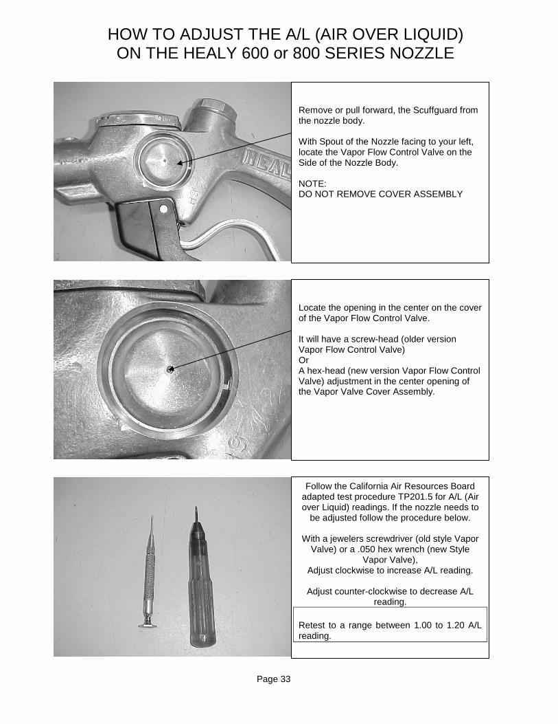
HOW TO ADJUST THE A/L (AIR OVER LIQUID) ON THE HEALY 600 or 800 SERIES NOZZLE
Remove or pull forward, the Scuffguard from the nozzle body. With Spout of the Nozzle facing to your left, locate the Vapor Flow Control Valve on the Side of the Nozzle Body. NOTE: DO NOT REMOVE COVER ASSEMBLY
Locate the opening in the center on the cover of the Vapor Flow Control Valve. It will have a screw-head (older version Vapor Flow Control Valve) Or A hex-head (new version Vapor Flow Control Valve) adjustment in the center opening of the Vapor Valve Cover Assembly.
Follow the California Air Resources Board adapted test procedure TP201.5 for A/L (Air over Liquid) readings. If the nozzle needs to
be adjusted follow the procedure below.
With a jewelers screwdriver (old style Vapor Valve) or a .050 hex wrench (new Style
Vapor Valve), Adjust clockwise to increase A/L reading.
Adjust counter-clockwise to decrease A/L
reading. Retest to a range between 1.00 to 1.20 A/L reading.
Page 33
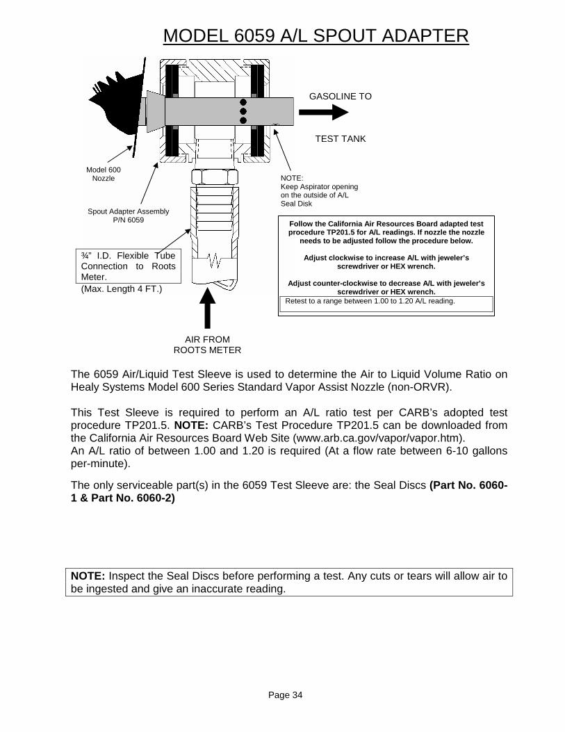
MODEL 6059 A/L SPOUT ADAPTER
The 6059 Air/Liquid Test Sleeve is used to determine the Air to Liquid Volume Ratio on Healy Systems Model 600 Series Standard Vapor Assist Nozzle (non-ORVR). This Test Sleeve is required to perform an A/L ratio test per CARB’s adopted test procedure TP201.5. NOTE: CARB’s Test Procedure TP201.5 can be downloaded from the California Air Resources Board Web Site (www.arb.ca.gov/vapor/vapor.htm). An A/L ratio of between 1.00 and 1.20 is required (At a flow rate between 6-10 gallons per-minute).
The only serviceable part(s) in the 6059 Test Sleeve are: the Seal Discs (Part No. 6060-1 & Part No. 6060-2)
NOTE: Inspect the Seal Discs before performing a test. Any cuts or tears will allow air to be ingested and give an inaccurate reading.
GASOLINE TO
TEST TANK
AIR FROM ROOTS METER
NOTE: Keep Aspirator opening on the outside of A/L Seal Disk
¾” I.D. Flexible Tube Connection to Roots Meter. (Max. Length 4 FT.)
Spout Adapter Assembly P/N 6059
Model 600 Nozzle
Follow the California Air Resources Board adapted t est procedure TP201.5 for A/L readings. If nozzle the n ozzle
needs to be adjusted follow the procedure below.
Adjust clockwise to increase A/L with jeweler’s screwdriver or HEX wrench.
Adjust counter-clockwise to decrease A/L with jewel er’s
screwdriver or HEX wrench. Retest to a range between 1.00 to 1.20 A/L reading.
Page 34
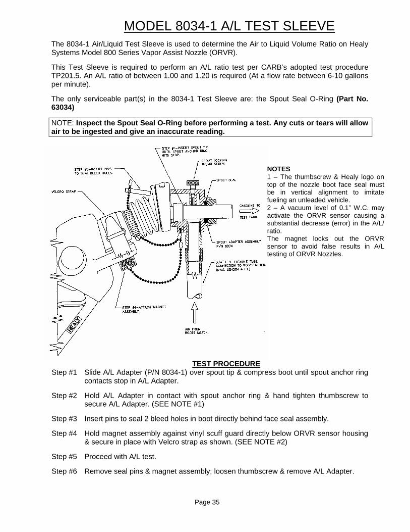
MODEL 8034-1 A/L TEST SLEEVE
The 8034-1 Air/Liquid Test Sleeve is used to determine the Air to Liquid Volume Ratio on Healy Systems Model 800 Series Vapor Assist Nozzle (ORVR).
This Test Sleeve is required to perform an A/L ratio test per CARB’s adopted test procedure TP201.5. An A/L ratio of between 1.00 and 1.20 is required (At a flow rate between 6-10 gallons per minute).
The only serviceable part(s) in the 8034-1 Test Sleeve are: the Spout Seal O-Ring (Part No. 63034)
NOTE: Inspect the Spout Seal O-Ring before performing a test. Any cuts or tears will allow air to be ingested and give an inaccurate reading.
TEST PROCEDURE Step #1 Slide A/L Adapter (P/N 8034-1) over spout tip & compress boot until spout anchor ring
contacts stop in A/L Adapter.
Step #2 Hold A/L Adapter in contact with spout anchor ring & hand tighten thumbscrew to secure A/L Adapter. (SEE NOTE #1)
Step #3 Insert pins to seal 2 bleed holes in boot directly behind face seal assembly.
Step #4 Hold magnet assembly against vinyl scuff guard directly below ORVR sensor housing & secure in place with Velcro strap as shown. (SEE NOTE #2)
Step #5 Proceed with A/L test.
Step #6 Remove seal pins & magnet assembly; loosen thumbscrew & remove A/L Adapter.
NOTES 1 – The thumbscrew & Healy logo on top of the nozzle boot face seal must be in vertical alignment to imitate fueling an unleaded vehicle. 2 – A vacuum level of 0.1” W.C. may activate the ORVR sensor causing a substantial decrease (error) in the A/L/ ratio. The magnet locks out the ORVR sensor to avoid false results in A/L testing of ORVR Nozzles.
Page 35

FIELD REPAIR INSTRUCTIONS 75-B SERIES HOSES
IMPORTANT NOTE: The Healy Series 75-B Hose Assemblies should be serviced by Healy qualified repair personnel only. Hoses should be inspected for kinks, flat spots, abraded outer cover (wire strands visible), and leaking fittings on a weekly basis.
The only serviceable parts on the hose are:
1. Part No. HB-2 O-Ring (see Item #1 Figure 1.). This O-Ring seals the hose fitting to the nozzle and the adapter. Check the hose for external leaks. Replace the O-Ring if necessary.
2. Part No. HB-4 Quad Seal (see Item #2 Figure 1.). This Quad Seal is used on the end of the hose that attaches to the breakaway assembly. If the symptom is meter creep, (fueling position display is counting up without dispensing product), check the HB-4 Quad Seal at the breakaway end of the hose and replace if necessary.
3. Part No. 291 O-Ring (see Item #3 Figure 1.). This O-Ring is used on the end of the hose that attaches to the nozzle or the hose adapter assembly. If the symptom is meter creep, (fueling position display is counting up without dispensing product), check the 291 O-Ring at the nozzle or adapter end of the hose and replace if necessary.
Helpful Hint: Lubricate any O-Ring or Quad Seal before installing the hose assembly into an adapter, breakaway, or nozzle assembly to make it easier to install and prevent the seal from getting cut. RULE OF THUMB: O-RINGS TO NOZZLE AND HOSE ADAPTER QUAD SEALS TO BREAKAWAY
Figure 1.
Page 36

Page 37

Page 38

Healy System Scheduled Maintenance Instructions
For 600 & 800 Series Nozzle System with VP1000
Dispenser Mounted Vacuum Pump The Healy System by design requires very limited maintenance. Initial problems are usually created by installation anomalies and are easily detected and repaired when the “ Vapor Return Line Test “ is performed. Periodic maintenance described here will eliminate problems, poor customer performance and maintain peak operation of the system. OPERATING NOTE: In parts of the country where the outside temperature drops below 35° F, the VP1000 vacuum pump motor will automatically run at a very low RPM to prevent freezing. This is normal operation.
Weekly Inspection to Be Performed By Station Manage r • Inspect each nozzle, hose, and breakaway for damage, loose connections or leaks.
• Inspect hoses for wear, severe kinks, cracks and splitting. Replace if wire braid is
visible.
• Inspect nozzles for damaged vapor boots or spouts. Any nozzle with a vapor collection boot which is missing, or which has one half of the mini-boot faceplate or greater missing is defective and should immediately removed from service until replaced or repaired. Spouts with visible damage must also be replaced.
• Test the VP1000 Vacuum Pump for normal operation using the following test
procedure: Normal operation will have the VP1000 Vacuum Pump r unning at low speed if only one side of a dispenser is activated and will run a t full speed if both sides of the dispenser are activated. NOTE: The VP1000 vacuum pump may continue to run fo r a few seconds after a nozzle is re-holstered. 1. Activate one side of the dispenser and the vacuum pump should come on. The VP1000 should come on immediately when the nozzle is lifted and the dispenser has reset from 8’s to 0’s. 2. Lift each nozzle one at a time on both sides to verify the vacuum pump is activated after the dispenser display resets from 8’s to 0’s. On some dispensers, activation comes on only after a product is selected. 3. Leaving one nozzle activated on the first side and with the pump now running, lift a nozzle on the other side of the dispenser and listen for a change of speed (increase) in the pump motor. 4. Leaving one side still activated verify the speed change by activating the remaining nozzles on the opposite side one at a time. If the above procedures can be confirmed by starting with the ‘other’ side, then the unit is correctly installed. Note that after the unit gets to second speed, it will not drop back to single speed until one nozzle is re-holstered. Page 39

Quarterly Inspection to Be Performed By Qualified S ervice Personnel • Perform Weekly Inspection prior to Quarterly inspection
• Inspect the VP1000 for loose or damaged vapor line connections as well as electrical
connections. Repair or replace if damaged.
• Verify proper operating range of the VP1000 (60 “ or greater of water column) with a 0-100 inch water column gage, utilizing the “VP1000 Vacuum Performance Test Procedure”.
• Inspect submersible and dispenser containment sumps for any leaks and repair as
needed. • Check product flow rate. Replace dispenser filters when flow rate is below 7 GPM /
26.5 LPM. If flow rates exceed 10 GPM / 37.8 LPM, install Healy Flow Limiters.
Annual Inspection to Be Performed By Qualified Serv ice Personnel • Perform weekly and quarterly inspection prior to Annual Inspection.
• Perform vapor return line tightness test. Repair all leaks.
• Perform pressure decay test. Repair all leaks.
• Perform A / L test on all nozzles. Adjust and replace as necessary. • Inspect Pressure / Vacuum Vent Valves for proper operation and loose or broken
seals. For more information on Healy Systems maintenance & testing procedures please call our Technical Services Department at: (603) 882-2472
Page 40
Healy Systems Limited Warranty Healy Systems Inc., products are warranted for work manship, performance, and materials when properly i nstalled, used and maintained. All Healy products, subassemblies, and raw materials are fully inspected and tested at the manufacturing facility. Healy warrants the workmanship and materi als to be free of defects for a period in accordanc e with the provisions stated below: • The nearest Healy Authorized Service Representative qualified to perform service on the defective equipment must perform
warranty service. Only Authorized Service Representatives are allowed to perform warranty service. Use of service personnel other than qualified Healy Service Representatives without prior written approval by Healy Systems Inc.; will void the warranty.
• The equipment has been installed according to the manufacturer’s instructions and diagrams. • During the warranty period, Healy Systems Inc. will, upon inspection and determination of a warranty claim, at its option, repair
or replace defective parts returned to its factory. Repaired or replaced parts will be shipped freight prepaid by Healy Systems. • Healy Systems is not responsible for labor or materials necessary to disconnect or connect the warranted product for return to
Healy. • Claims for warranty repair or replacement service must have a written “Returned Material Authorization” (RMA) from Healy
Systems, and must be shipped freight prepaid to Healy Systems for inspection. • The manufacturer reserves the right to make changes in the design or to make additions or improvements with respect to its
products without incurring any obligation to modify or install same on previously manufactured products.
THIS WARRANTY IS A LIMITED WARRANTY. ANYTHING IN TH E WARRANTY NOTWITHSTANDING, IMPLIED WARRANTIES FOR FITNESS, PARTICULAR PURPOSE AND MERCHANTABILITY SHA LL BE LIMITED TO THE DURATION OF THE EXPRESS WARRANTY. HEALY SYSTEMS EXPRESSLY DISCLAIMS AND EXC LUDES ANY LIABILITY FOR CONSEQUENTIAL OR INCIDENTAL
DAMAGE FOR BREACH OF ANY EXPRESS OR IMPLIED WARRANT Y.
Healy Systems In c. – 18 Hampshire Drive – Hudson, New Hampshire 03051 – Tel: (603) 882-2472 - Fax: (603) 882-5189
K: \JWFILES\POLICY\WARRANTY 07/98
Nozzles – New & Rebuilt Healy warrants the workmanship and materials to be free of defects for a period of one (1) year from the date of shipment from Healy. Exclusions: This warranty excludes the “rubber” parts at the front of the nozzle (i.e., boot, scuffguard, face seal assembly, etc.) or the spout or parts that have been subject to misuse, handling or incorrect installation. Hoses – Including Breakaway Pigtail Healy warrants the workmanship and materials to be free of defects for a period of one (1) year from the date of shipment from Healy. Central Vacuum Sources –9000 Mini-jets, VP500, & 20 00 Blower Assemblies Healy warrants the workmanship and materials to be free of defects for a period of one (1) year from the date of shipment from Healy. Dispenser Mounted Vacuum Source – VP1000 Healy warrants the workmanship and materials to be free of defects for a period of two (2) years from the date of shipment from Healy. This applies to the vacuum pump and motor assembly only. The mounting Hardware and the Interface Module are warranted for workmanship and materials to be free of defects for a period of one (1) year from the date of shipment from Healy. Dispenser Mounted Vacuum Source – VP1200 Healy warrants the workmanship and materials to be free of defects for a period of one (1) year from the date of shipment from Healy. Vapor Recovery System Monitor – 6280A Healy warrants the workmanship and materials to be free of defects for a period of one (1) year from the date of shipment from Healy. Exclusions: Consumable items such, as printer ribbons and paper are not warranted. The use of a consumable item not specified by Healy will void the warranty. Accessories Healy warrants the workmanship and materials to be free of defects for a period of one (1) year from the date of shipment from Healy.
Upgrade Kits & Retrofit Kits Healy warrants the workmanship and materials to be free of defects for a period of one (1) year from the date of shipment from Healy. Spare Parts Healy warrants the workmanship and materials to be free of defects for a period of ninety (90) days from the date of shipment from Healy. General Exclusions
1. This warranty shall not apply to any product which has been altered in any way or which has been repaired by any party other than an authorized Healy Systems Service Representative or when such failure is due to misuse or conditions of use.
2. Use of non-Healy replacement parts, the unauthorized addition of non-Healy items to Healy equipment, and the unauthorized alteration of Healy equipment will void this warranty.
3. Healy shall, as to each defect, be relieved of all obligations and liabilities under a components warranty if the vapor recovery systems or components have been operated with any accessory, equipment, or part not specifically approved by Healy and not manufactured by Healy to Healy’s design and specifications. Provided, that this provision shall not apply to any accessory, equipment or part in use which does not affect the safety or functionality of the vapor recovery system or system component.
4. Healy Systems makes no warranty with respect to the Healy performance of equipment or Healy’s performance of services under this agreement, express or implied, and Healy Systems hereby disclaims the implied warranties of merchantability and fitness for a particular purpose.
5. This warranty shall not cover any Healy Systems component in contact with fuels containing greater than 15% methanol, 15% ethanol, or 15% MTBE by Volume.
6. Any component(s), which is exposed to M85/E85 fuel (or other alcohol rich fuel), is not covered under the Healy Systems warranty.
Page 41

The material included in this Installation & Servic e Guide Manual is accurate at the date of publication. The intent of this manual is to assist. If further assistance is required, please c ontact the Healy Technical Service Department at: 1-(603)-882-2472, in New Hampshire, 8 am to 5 pm Eastern Standard Time.
SYSTEMS, INC.
18 Hampshire Drive Hudson, NH 03051 USA
Tel: (603) 882-2472 Fax: (603) 882-5189
Web Site: www.healysystems.com Email: [email protected]

HEALY SYSTEMS VP1000 DISPENSER MOUNTED VAPOR RECOVERY SYSTEM MANUAL FOR
GASOLINE REFUELING FACILITIES
THIS MANUAL MUST BE LEFT WITH FACILITY
MANAGEMENT
THIS MANUAL CONTAINS MATERIALS
REQUIRED BY YOUR STATE TO BE ON SITE AT ALL TIMES
INSTALLER MUST NOT TAKE THESE DOCUMENTS AWAY WITH THEM.
SITE NAME:
ADDRESS:
DATE INSTALLED:
INSTALLING CONTRACTOR:
SERVICE CONTACT:
SERVICE TELEPHONE #: