Health Building Note 04-01 Supplement 1 Isolation … 1.1 The key to effective isolation on acute...
28
Health Building Note 04-01 Supplement 1 Isolation facilities for infectious patients in acute settings
Transcript of Health Building Note 04-01 Supplement 1 Isolation … 1.1 The key to effective isolation on acute...

Health Building Note 04-01Supplement 1 Isolation facilities for infectious patients in acute settings

Health Building Note 04-01 Supplement 1 Isolation facilities for infectious patients in acute settings

Health Building Note 04-01 Supplement 1 – Isolation facilities for infectious patients in acute settings
ii
© Crown copyright 2013
Terms of use for this guidance can be found at http://www.nationalarchives.gov.uk/doc/open-government-licence/

iii
Preface
About Health Building NotesHealth Building Notes give “best practice” guidance on the design and planning of new healthcare buildings and on the adaptation/extension of existing facilities.
They provide information to support the briefing and design processes for individual projects in the NHS building programme.
The Health Building Note suiteHealthcare delivery is constantly changing, and so too are the boundaries between primary, secondary and tertiary care. The focus now is on delivering healthcare closer to people’s homes.
The Health Building Note framework (shown below) is based on the patient’s experience across the spectrum of care from home to healthcare setting and back, using the national service frameworks (NSFs) as a model.
Health Building Note structureThe Health Building Notes have been organised into a suite of 17 core subjects.
Care-group-based Health Building Notes provide information about a specific care group or pathway but cross-refer to Health Building Notes on generic (clinical) activities or support systems as appropriate.
Core subjects are subdivided into specific topics and classified by a two-digit suffix (-01, -02 etc), and may be further subdivided into Supplements A, B etc.
All Health Building Notes are supported by the overarching Health Building Note 00 in which the key areas of design and building are dealt with.
ExampleThe Health Building Note on accommodation for adult in-patients is represented as follows:
“Health Building Note 04-01: Adult in-patient facilities”
The supplement to Health Building Note 04-01 on isolation facilities is represented as follows:
“Health Building Note 04-01: Supplement 1 – Isolation facilities for infectious patients in acute settings”
Health Building Note number and series title Type of Health Building Note
Health Building Note 00 – Core elements Support-system-basedHealth Building Note 01 – Cardiac care Care-group-basedHealth Building Note 02 – Cancer care Care-group-basedHealth Building Note 03 – Mental health Care-group-basedHealth Building Note 04 – In-patient care Generic-activity-basedHealth Building Note 05 – Older people Care-group-basedHealth Building Note 06 – Diagnostics Generic-activity-basedHealth Building Note 07 – Renal care Care-group-basedHealth Building Note 08 – Long-term conditions/long-stay care Care-group-basedHealth Building Note 09 – Children, young people and maternity services Care-group-basedHealth Building Note 10 – Surgery Generic-activity-basedHealth Building Note 11 – Community care Generic-activity-basedHealth Building Note 12 – Out-patient care Generic-activity-basedHealth Building Note 13 – Decontamination Support-system-basedHealth Building Note 14 – Medicines management Support-system-basedHealth Building Note 15 – Emergency care Care-group-basedHealth Building Note 16 – Pathology Support-system-based

Health Building Note 04-01 Supplement 1 – Isolation facilities for infectious patients in acute settings
iv
Other resources in the DH Estates and Facilities knowledge series
Health Technical Memoranda
Health Technical Memoranda give comprehensive advice and guidance on the design, installation and operation of specialised building and engineering technology used in the delivery of healthcare (for example medical gas pipeline systems, and ventilation systems).
They are applicable to new and existing sites, and are for use at various stages during the inception, design, construction, refurbishment and maintenance of a building.
All Health Building Notes should be read in conjunction with the relevant parts of the Health Technical Memorandum series.
Activity DataBase (ADB)
The Activity DataBase (ADB) data and software assists project teams with the briefing and design of the healthcare environment. Data is based on guidance given in the Health Building Notes, Health Technical Memoranda and Health Technical Memorandum Building Component series.
1. Room data sheets provide an activity-based approach to building design and include data on personnel, planning relationships, environmental considerations, design character, space requirements and graphical layouts.
2. Schedules of equipment/components are included for each room, which may be grouped into ergonomically arranged assemblies.
3. Schedules of equipment can also be obtained at department and project level.
4. Fully loaded drawings may be produced from the database.
5. Reference data is supplied with ADB that may be adapted and modified to suit the users’ project-specific needs.
NoteThe sequence of numbering within each subject area does not necessarily indicate the order in which the Health Building Notes were or will be published/printed. However, the overall structure/number format will be maintained as described.

v
This Health Building Note sets out practical guidance on how to provide safe, effective isolation facilities for infectious patients (source isolation) that are simple to use and meet the needs of most patients on acute general wards.
This guidance describes:
• how a single-bed room with en-suite sanitary facilities can be used to provide effective isolation for patients with non-airborne diseases;
• how a ventilated single-bed room with en-suite facilities can provide an isolation room for patients who have an infection that can be spread by the airborne route.
It can be used for both new-build schemes and the upgrading of existing accommodation.
Room layouts are included as illustrative examples; other room configurations are possible.
It is advised that this Health Buulding Note be read in conjunction with:
• ‘Infection control in the built environment’ (DH, 2002), which provides information about how good design can prevent cross-infection in healthcare premises generally;
• Health Building Note 04-01 – ‘Adult in-patient accommodation’, which covers the planning and design of in-patient facilities for adults and includes space standards for bed areas (including isolation rooms and lobbies).
• ‘Single-bed room: design manual’, in Health Building Note 00-03 – ‘Clinical and clinical support spaces’, which provides detailed design information and layouts for single-bed rooms.
This document part supersedes Health Building Note 04-01 Supplement 1 (2005), specifically the guidance therein that relates to rooms used for source isolation. It does not supersede the guidance on protective isolation.
Executive summary

Health Building Note 04-01 Supplement 1 – Isolation facilities for infectious patients in acute settings
vi
Catherine Noakes, University of Leeds School of Civil Engineering
Francis Marsh, Department of Health, Social Services and Public Safety (DHSSPS), Northern Ireland
Malcolm Thomas, Consulting engineer
Peter Hoffman, Health Protection Agency
Tom Jones, Building Services Research and Information Association (BSRIA)
William Booth, Building Services Research and Information Association (BSRIA)
Acknowledgements

vii
Contents
PrefaceExecutive summaryAcknowledgements1 Introduction 1
Exclusions2 Options for provision 2
Single-bed room Options for preventing the spread of pathogens that are transmitted by the airborne route
Negative pressure room Positive pressure ventilated lobby (PPVL) room Extract ventilation – negative pressure and PPVL rooms Documentation
3 Converting existing facilities 8Converting an en-suite single-bed room Converting a single-bed room without en-suite facilities Creating an en-suite single-bed room with ventilated lobby Converting a multi-bed bay
4 Fire safety 9Appendix 1 – Example room layouts 10Appendix 2 – Acceptance testing of isolation rooms/suites 17
Definitions Isolation suite Isolation room envelope
Validation – isolation room air permeability Validation and annual revalidation
Filtration test standards Air permeability tests System operating standard
Record-keeping References 19

Health Building Note 04-01 Supplement 1 – Isolation facilities for infectious patients in acute settings
viii

1
1.1 The key to effective isolation on acute general wards is the provision of single-bed rooms with en-suite sanitary facilities. Single-bed rooms reduce the risk of cross-infection for non-airborne diseases and help to lower the incidence of healthcare¬associated infections. Most patients requiring isolation on acute general wards can be isolated in single-bed rooms with en-suite facilities. All single-bed rooms in new-build hospitals and wards should have en-suite facilities so that they can be used to isolate patients, among other reasons. It is the Department of Health’s policy that any new build or major reconfiguration should have as a minimum 50% single-bed rooms.
1.2 The infection control team should be closely involved with all aspects of planning for, and determining the provision of, isolation facilities. When undertaking a project, a multi-disciplinary approach should involve the:
• infection control team and clinical team;
• architect and designer;
• building contractor and mechanical/electrical maintenance service providers;
• in-house estates team.
1.3 In accordance with ‘The Code of Practice on the the prevention and control of infections and related guidance’ (2010), it is recommended that all
registered providers put in place systems to manage and monitor the prevention and control of infection. These systems use risk assessments and consider how susceptible patients are and any risks that their environment and other users may pose to them.
1.4 The provision of isolation rooms that are switchable from positive to negative air pressure is not recommended because of the risk to people inside and outside the room in the event of the setting being incorrect.
1.5 The guidance on PPVL and negative pressure isolation suites in this document is based on a model that was validated by the Building Services Research and Information Association (BSRIA) and the University of Leeds. The complete validation process and results obtained will be available from BSRIA (see link in References section).
Exclusions1.6 This Health Building Note does not describe the
specialist facilities required in high security infectious disease units, isolation wards for cohorting groups of infectious patients, protective isolation for severely immuno-compromised patients, critical care areas and special care baby units. It focuses on single occupancy isolation rooms only.
1 Introduction

Health Building Note 04-01 Supplement 1 – Isolation facilities for infectious patients in acute settings
2
2.1 This chapter describes:
• how a single-bed room with en-suite sanitary facilities can be used to provide effective isolation for patients with non-airborne diseases (see paragraph 2.2);
• how a ventilated single-bed room with en-suite sanitary facilities can provide an isolation room for patients who have an infection that can be spread by the airborne route (see paragraph 2.9).
Single-bed room 2.2 A single-bed room with en-suite sanitary facilities is
a simple, cost-effective way to provide isolation, and will meet the needs of most patients on general wards. An example layout for a new-build single-bed room with en-suite facilities is shown in sheet 1 (Appendix 1).
2.3 Detailed design guidance and space standards are given in Health Building Note 04-01 – ‘Adult in-patient accommodation’ and ‘Single-bed room’ in Health Building Note 00-03 – ‘Clinical and clinical support spaces’. Key considerations are the inclusion of:
• en-suite sanitary facilities;
• optional lobby – if a lobby is not provided, space is needed for personal protective equipment and its disposal;
• clinical wash-hand basin in the room and in the lobby, if provided;
• good patient observation facilities;
• design features that enhance patient comfort (for example, ability to see out of the room).
2.4 Openable exterior windows and suspended tiled ceilings are optional.
2.5 See also Health Facilities Note 30 – ‘Infection control in the built environment’.
2.6 Some patients with infections need to stay in isolation in hospital for long periods. The number of visitors they receive and the length of time they can spend with them may be restricted. This means that patients who are already vulnerable, but not necessarily physically severely incapacitated, will be confined to the room for sometimes several weeks and can experience long periods of boredom.
2.7 Accommodation for these patients should be stimulating and as comfortable as possible. Designers should try to achieve a balance between the need for a clean environment and the comfort of patients. A number of publications describe in detail evidence that supports the concept that a therapeutic environment has a positive effect on a patient’s general feeling of well-being; reduces the length of stay for many patients; reduces depression, confusion and aggressive episodes; and significantly increases a patient’s level of satisfaction with the overall quality of their care (see Health Building Note 04-01 – ‘Adult in-patient accommodation’).
2.8 If patients are to stay in an isolation room, it is important that they are able to see staff from their beds. This reduces the psychological problems of isolation. Staff should also be able to see the patient in case of emergency. Observation windows should have integral privacy blinds or glass that can be obscured electronically, which can be controlled by both staff and patients. The sense of containment can also be reduced by providing outside views using windows with low sills.
2 Options for provision

2 Options for provision
3
Options for preventing the spread of pathogens that are transmitted by the airborne route
NoteThe isolation room should be physically constructed so that undesirable air flow in or out is restricted. This is described as the “permeability” of the room, which in simple terms is a measure of how leaky it is. If air can leak between an isolation room and an adjacent area in either direction, then this presents a route for the transmission of an airborne infection (see also Appendix 2).
2.9 A ventilated single-bed room with en-suite facilities can provide an isolation room for patients who have an infection that can be spread by the airborne route. This includes chickenpox, measles and some cases of pulmonary tuberculosis. It is for local clinical risk assessment to decide which patients will need to be nursed in these facilities.
2.10 The two options are:
• a room with negative pressure ventilation (see paragraph 2.11) or;
• neutral pressure room with a positive pressure ventilated lobby (PPVL – see paragraph 2.21).
Negative pressure room
2.11 This room is at negative pressure to the corridor and other adjacent areas (except for its en-suite).
2.12 The robust direction of air flow is more important than the numerical value of the pressure differential (see paragraph 2.15, ‘Basic design parameters’).
2.13 The inflow of air into the room (negative pressure) prevents the escape of contaminated air to surrounding areas; the ventilation in the room dilutes airborne pathogens.
Room criteria
• A sealed solid integrated ceiling should be installed.
• Windows to the exterior should be unopenable and well-sealed.
• Service penetrations should be minimised to support the room being well-sealed.
• A transfer grille to en-suite facility should be provided.
• Doors are a critical part of the design. The door from the corridor to the patient’s room should be well hung and open into the patient’s room. It should be fitted with a door closer to ensure that the pressure regime is maintained. The door between the patient’s room and en-suite should be well hung and swing both ways. It may be “undercut” or fitted with a transfer grille in its lower half in order to promote an inflow of air to the en-suite.
2.14 For space requirements, see Health Building Note 04-01 – ‘Adult in-patient accommodation’.
Basic design parameters
2.15 The patient’s room should have around 10 air changes per hour and should be compatible with patient comfort. Air flow should be fully mixed to ensure good dilution and removal of airborne pathogens from the room space. The pressure differential to surrounding areas should indicate a definite inward flow of air. Any value in excess of 5 pascals should be sufficient to achieve and maintain this condition. An extract should be provided in the patient’s room.
NoteCareful positioning of the extract should be considered. If supply and extract are adjacent to each other, short-circuiting of air flow will occur and although the room may seem to have a suitable air change rate and pressure regime, it will be inefficiently ventilated and not well-mixed.
2.16 To be effective, the extract in the en-suite should be sized to handle approximately two-thirds of the total isolation room’s extract requirements.
2.17 The en-suite facility should be sized according to the recommendations given in Health Building Note 04-01 – ‘Adult in-patient accommodation’.
2.18 If the room has both mechanically supplied and extracted air, these should be interlocked so that, should the extract fail, the supply will cut out (otherwise the room would be under positive pressure). Appropriate standby provision should be identified (for example connection to the essential power supply or uninterruptible power supplies) to enable continuity of supply should a mains power failure occur (see Health Technical Memorandum 06-01 – ‘Electrical services supply and distribution’).

Health Building Note 04-01 Supplement 1 – Isolation facilities for infectious patients in acute settings
4
Monitoring and record keeping
2.19 The pressure differential between the patient room and corridor should be monitored continuously (for example, by using a differential pressure sensor). Failure to maintain a negative pressure should activate an alarm at a designated nurse station as well as in the estates department via a building management system. There should be a delay on the alarm to allow doors to be opened, resulting in a temporary zero pressure differential, to allow the transfer of a bed into and out of the room. Note that when the bed is moved into or out of the room, the patient is NOT in isolation.
2.20 A magnehelic pressure gauge should show the pressure differential between the patient room and the corridor. It should be mounted at eye level on the corridor wall adjacent to the entry door. The gauge should be clearly marked to identify the isolation room to which it refers.
Positive pressure ventilated lobby (PPVL) room
2.21 This is a single-bed room with a PPVL and en-suite sanitary facilities with extract ventilation (see sheet 2 of Appendix 1 for an example layout).
Room criteria
• One or more pressure stabilisers should be installed above the door between the lobby and the patient’s room.
• A suitable extract system to the en-suite facility should be provided.
• A transfer grille in the lower section of the en-suite door should be installed.
• To support the room being well-sealed, the detail of the construction joints between elements of the building and service penetrations will be critical to achieving the air-leakage standard demanded. The joints should be carefully sealed as construction progresses and service penetrations minimised, as they will be inaccessible once the inner finish is applied (see Appendix 2 on air leakage).
• The door between the corridor and the lobby should open into the lobby and be fitted with a door closer. The door between the lobby and patient’s room should open back into the lobby and be fitted with a door closer. This is to ensure that the closure of both doors is aided by the lobby pressure, thus maintaining the air flow direction and pressure regime of the suite.
• If bed entry to the suite is through the lobby, one-and-a-half-leaf door sets will need to be fitted. Space constraints may make it necessary to hang the half-leaf from parliament hinges so that it can be opened back against the corridor or the wall of the patient’s room (see Appendix 1, sheets 2, 5 and 6). Once the bed has passed through the lobby, the half-leaf should be latched shut. Entry for personnel will be via the single door leaf. An oversized door should not be used in place of the one-and-a-half-leaf door set.
2.22 For space requirements, see Health Building Note 04-01 – ‘Adult in-patient accommodation’.
Basic design parameters
2.23 The patient’s room is to have 10 air changes per hour mechanical air change rate. The entry lobby should have a positive pressure of between 8 and 12 pascals with respect to the corridor. The en-suite facility is to have at least 10 air changes per hour and be at a negative pressure with respect to the patient’s room. Table 1 gives nominal design values calculated for rooms of the size stated.
2.24 Modifying or failing to provide one element of the system will jeopardise the performance of the system as a whole.
2.25 An extract terminal should be fitted at high level in the en-suite facility.
2.26 A transfer grille should be fitted at low level in the door between the patient’s room and the en-suite facility.
2.27 A pressure stabiliser of the balanced blade type, set to operate at 10 pascals, should be fitted above the door between the lobby and the patient’s room. The stabiliser should be visible so that its correct operation can be seen. It should be of a style that will operate silently, and be correctly sized and positioned so that it does not cause a draught that would be uncomfortable for patients.
NoteIt is critical to the correct function of this design concept that the stabiliser be fitted as described and the transfer grille in the en-suite door also be fitted as described. This will set up a cyclonic circulation in the patient’s room and provide the desired dilution protection levels.

2 Options for provision
5
2.28 A direct reading gauge showing the pressure in the lobby with respect to the corridor should be mounted at eye level on the corridor wall adjacent to the lobby entry door. The gauge and lobby entry door should be clearly marked to identify the isolation room to which they refer.
2.29 Door undercuts are not recommended.
Supply ventilation for PPVL rooms
2.30 The supply air handling unit (AHU) and distribution ductwork should be clearly marked to identify the isolation suite that they serve. Service, maintenance, cleaning and filter change of the system will be subject to a permit to work.
2.31 A G3 pre-filter and a final filter to at least F7 standard should be fitted in the AHU.
2.32 In order to future-proof the system, the supply terminal in the lobby should be of a type that can accept a HEPA filter.
Monitoring and record keeping 14371
2.33 A record of pressure differentials, observed and recorded once per nursing shift, should be made. Ward staff should be made aware of what to do if the readings are out of specification.
Extract ventilation – negative pressure and PPVL rooms
2.34 The extract fan unit should preferably be located outside the building so that all ductwork within the building is under negative pressure. Access and cleaning hatches should only be fitted where absolutely necessary. If fitted they should be of the
Table 1 PPVL isolation suite – ventilation parameters
Room Parameter Nominal design values
Lobby Room volume Bed access lobby (5 m2 × 2.7 m) Personnel access lobby (4 m2 × 2.7 m)
13.5 m3
10.8 m3
Pressure differential to corridor Nominally 10 pascalsSupply air flow (see Note 3) Bed access lobby – 238 L/s
Personnel access lobby – 208 L/sAir change rate Bed access lobby – 63 per hour
Personnel access lobby – 69 per hourIsolation room Room volume (19 m2 × 3 m) 57 m3
Pressure differential to corridor Nominally zeroRoom air flow 158 L/sAir change rate 10 per hour
En-suite Room volume (6 m2 × 2.7 m) 16.2 m3
Pressure differential to isolation room NegativeExtract air flow 158 L/s (if extract is fitted in the isolation room
this reduces to approximately 100 L/s in the en-suite with approximately 58 L/s extract in the isolation room)
Air change rate At least 10 per hourNotes
1. In this example, the design parameters are based on Health Building Note 04-01 – ‘Adult in-patient accommodation’. The en-suite is sized to comply with BS 8300 accessibility requirements.
2. The air flow rates quoted do not include any allowance for construction leakage. Airtightness specifications are given in Approved Document L of the Building Regulations (2010). See also the Air Tightness Testing & Measurement Association’s (ATTMA) ‘Technical Standard L2: Measuring air permeability of building envelopes (non-dwellings)’ (see Appendix 2).
3. These are typical values based on standard room sizes. The actual volume of air required will be the sum of the air required to provide 10 air changes per hour in the patient’s room + the air leakage through the door between the lobby and corridor at a differential pressure of 10 pascals. (See Appendix 4 in Health Technical Memorandum 03-01 Part A for leakage rate for single and double doors at 10 pascals.)

Health Building Note 04-01 Supplement 1 – Isolation facilities for infectious patients in acute settings
6
sealed type and marked with a biohazard symbol. If the fan has to be located inside the building, it should be as close as practicable to the outside. The extract fan motor should be mounted out of the air stream and should be capable of being changed without withdrawing the impeller or opening up the ductwork. The extract fan should draw its power from the essential electrical system.
2.35 Extract filters will not be required provided that the fan can discharge in a safe location 3000 mm above the building height. If extract filters are fitted, they should be in a “safe change housing” outside the building on the suction side of the fan. Extract filters, where fitted, should be of HEPA grade. Even if filtered, extract air should not be recirculated.
2.36 Extract ductwork, the fan and discharge stack should be clearly marked to identify the isolation suite that they serve. Service, maintenance, cleaning and filter change of the system will be subject to a permit to work.
2.37 Ideally each isolation suite should have its own dedicated supply and extract system. If two or more suites share a ventilation system, there will be an inevitable increase in the complexity of the system and a corresponding reduction in reliability and serviceability. Routine maintenance or breakdown of the ventilation system will result in failure of all suites that it serves; therefore, ideally each such isolation suite should have its own dedicated AHU.
2.38 In a high-rise building, a common supply and extract system may be the only feasible solution. In this case, run and standby fans would be required for the extract, and a duplicate supply unit may be considered necessary. The common supply and extract systems will need to be controlled to ensure a constant volume in each isolation suite branch regardless of the number in use.
2.39 Ductwork should be kept as direct and simple as possible.
Patient’s roomTransfer
grille
Pressurestabiliser Corridor
Doorway
En-suiteLobby
Plantroom
Extract
E
3000 mm
Fire/PlantIsolation damper
Supply Air HandlingUnit (AHU)
S
Spectacle plate
Figure 1 Extract ventilation – negative pressure and PPVL rooms

2 Options for provision
7
Documentation
2.40 A logbook retained by the estates department will be required for each isolation room/suite. It should contain the following information:
• a schematic layout of the isolation room/suite and ventilation system serving it;
• information on the ventilation design parameters;
• a record of the actual ventilation performance at initial validation;
• records of the annual validations;
• records of any routine service and maintenance activities;
• records of any repairs or modifications.
Health Building Note 04-01 Supplement 1 – Isolation facilities for infectious patients in acute settings
8
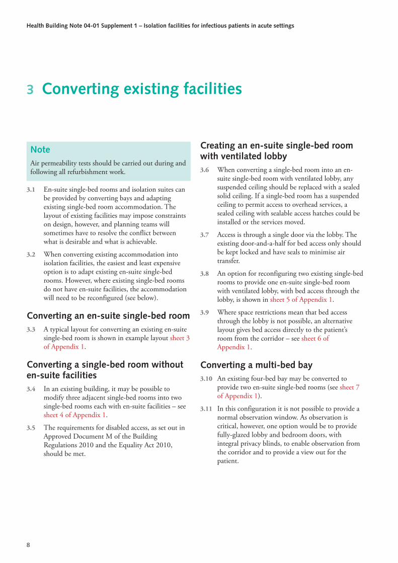
NoteAir permeability tests should be carried out during and following all refurbishment work.
3.1 En-suite single-bed rooms and isolation suites can be provided by converting bays and adapting existing single-bed room accommodation. The layout of existing facilities may impose constraints on design, however, and planning teams will sometimes have to resolve the conflict between what is desirable and what is achievable.
3.2 When converting existing accommodation into isolation facilities, the easiest and least expensive option is to adapt existing en-suite single-bed rooms. However, where existing single-bed rooms do not have en-suite facilities, the accommodation will need to be reconfigured (see below).
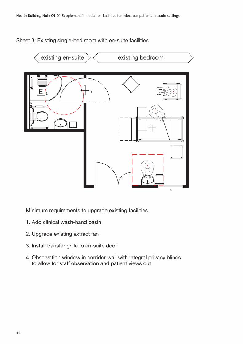
Converting an en-suite single-bed room 3.3 A typical layout for converting an existing en-suite
single-bed room is shown in example layout sheet 3 of Appendix 1.
Converting a single-bed room without en-suite facilities 3.4 In an existing building, it may be possible to
modify three adjacent single-bed rooms into two single-bed rooms each with en-suite facilities – see sheet 4 of Appendix 1.
3.5 The requirements for disabled access, as set out in Approved Document M of the Building Regulations 2010 and the Equality Act 2010, should be met.
Creating an en-suite single-bed room with ventilated lobby 3.6 When converting a single-bed room into an en-
suite single-bed room with ventilated lobby, any suspended ceiling should be replaced with a sealed solid ceiling. If a single-bed room has a suspended ceiling to permit access to overhead services, a sealed ceiling with sealable access hatches could be installed or the services moved.
3.7 Access is through a single door via the lobby. The existing door-and-a-half for bed access only should be kept locked and have seals to minimise air transfer.
3.8 An option for reconfiguring two existing single-bed rooms to provide one en-suite single-bed room with ventilated lobby, with bed access through the lobby, is shown in sheet 5 of Appendix 1.
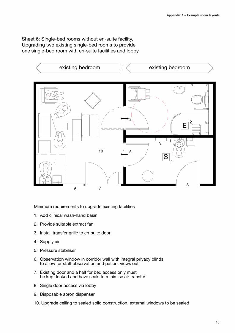
3.9 Where space restrictions mean that bed access through the lobby is not possible, an alternative layout gives bed access directly to the patient’s room from the corridor – see sheet 6 of Appendix 1.
Converting a multi-bed bay 3.10 An existing four-bed bay may be converted to
provide two en-suite single-bed rooms (see sheet 7 of Appendix 1).
3.11 In this configuration it is not possible to provide a normal observation window. As observation is critical, however, one option would be to provide fully-glazed lobby and bedroom doors, with integral privacy blinds, to enable observation from the corridor and to provide a view out for the patient.
3 Converting existing facilities

9
4.1 Where isolation rooms/suites are provided for the purposes of preventing the risk of spreading healthcare-associated infections to other parts of a ward, the normal fire safety precautions for single-bed room accommodation apply.
4.2 In the case of an isolation room with a PPVL, the ventilation system should comply with Health Technical Memorandum 03-01 – ‘Specialised ventilation for healthcare premises’. Where the ventilation system passes through a compartment wall, sub-compartment wall or cavity barrier, it should be fitted with fire and or smoke dampers in
accordance with Figure 10 of Health Technical Memorandum 05-02 – ‘Guidance in support of functional provisions for healthcare premises’. If the ductwork is fire-rated, the system only requires a fire damper at its junction with the AHU as shown in the diagram in Figure 1, ‘Extract ventilation – negative pressure and PPVL rooms’.
4.3 It is recommended that any discussions on fire safety should be discussed with the healthcare organisation’s fire safety adviser, the building control authority and the local fire-and-rescue service.
4 Fire safety

Health Building Note 04-01 Supplement 1 – Isolation facilities for infectious patients in acute settings
10
A1.1 The room layouts in this appendix are examples and are intended as a guide. Other room configurations are possible. Refer to ‘Health Building Note 04-01 – Adult in-patient accommodation’ and ‘Single-bed room’ in Health Building Note 00-03 – ‘Clinical and clinical support spaces’, which give definitive design
guidance and space standards for multi-bed rooms and single-bed rooms with en-suite facilities.
A1.2 For guidance on the sanitary assemblies used in these layouts, see Health Building Note 00-10 Part C – ‘Sanitary assemblies’.
Appendix 1 – Example room layouts
4
33
2E
Sheet 1: New build single room with en-suite facilities
1
Minimum requirements
1. Clinical wash-hand basin
2. Provide suitable extract fan
3. Transfer grille to en-suite door
4. Observation window in corridor wall with integral privacy blinds to allow for staff observation and patient views out

Appendix 1 – Example room layouts
11
74
1
54
81
S
3 E2
9
Sheet 2: New build single room with en-suite facilities and lobby
Minimum requirements
1. Clinical wash-hand basin
2. Provide suitable extract fan
3. Install transfer grille to en-suite door
4. Supply air
5. Pressure stabiliser
6. Observation window in corridor wall with integral privacy blinds to allow for staff observation and patient views out
7. Double door for personnel and bed access
8. Disposable apron dispenser
9. Ceiling to be sealed solid construction, external window to be sealed
Health Building Note 04-01 Supplement 1 – Isolation facilities for infectious patients in acute settings
12
Minimum requirements to upgrade existing facilities
1. Add clinical wash-hand basin
2. Upgrade existing extract fan
3. Install transfer grille to en-suite door
4. Observation window in corridor wall with integral privacy blinds to allow for staff observation and patient views out
4
existing en-suite
E 2 3
existing bedroom
Sheet 3: Existing single-bed room with en-suite facilities

Appendix 1 – Example room layouts
13
existing bedroom
2
Minimum requirements to upgrade existing facilities
1. Add clinical wash-hand basin
2. Provide suitable extract fan
3. Install transfer grille to en-suite door
4. Observation window in corridor wall with integral privacy blinds to allow for staff observation and patient views out
5. En-suite facility
4 4
existing bedroom
E
5
3
3
5
E 2
existing bedroom
CHA058
Sheet 4: Single-bed rooms without en-suite facility.Upgrading three existing single-bed rooms to providetwo single-bed rooms with en-suite facilities

Health Building Note 04-01 Supplement 1 – Isolation facilities for infectious patients in acute settings
14
1
existing bedroom
6
1
8
54
S
3
existing bedroom
2
7
E
9
10
Sheet 5: Single-bed rooms without en-suite facility.Upgrading two existing single-bed rooms to provide onesingle-bed room with en-suite facilities and alternative lobby
Minimum requirements to upgrade existing facilities
1. Add clinical wash-hand basin
2. Provide suitable extract fan
3. Install transfer grille to en-suite door
4. Supply air
5. Pressure stabiliser
6. Observation window in corridor wall with integral privacy blinds to allow staff observation and patients views out
7. Double door for personnel and bed access
8. Disposable apron dispenser
9. Upgrade ceiling to sealed solid construction, external windows to be sealed
10. En-suite facility
Appendix 1 – Example room layouts
15
1
1
4
76
5
S
3
9
8
2E
existing bedroom existing bedroom
10
Sheet 6: Single-bed rooms without en-suite facility.Upgrading two existing single-bed rooms to provideone single-bed room with en-suite facilities and lobby
Minimum requirements to upgrade existing facilities
1. Add clinical wash-hand basin
2. Provide suitable extract fan
3. Install transfer grille to en-suite door
4. Supply air
5. Pressure stabiliser
6. Observation window in corridor wall with integral privacy blinds to allow for staff observation and patient views out
7. Existing door and a half for bed access only must be kept locked and have seals to minimise air transfer
8. Single door access via lobby
9. Disposable apron dispenser
10. Upgrade ceiling to sealed solid construction, external windows to be sealed

Health Building Note 04-01 Supplement 1 – Isolation facilities for infectious patients in acute settings
16
existing four bed ward
Minimum requirements
1. Clinical wash-hand basin
2. Provide suitable extract fan
3. Transfer grille to en-suite door
4. En-suite facility
5. Doors to be fully glazed, with integral privacy blinds, to allow staff observation and patients views out
4 E2
3
55
E 4
2
3
Sheet 7: Upgrading existing four-bed ward to providetwo single-bed rooms with en-suite facilities
17
Definitions
Isolation suite
A2.1 Includes the entry lobby, patient’s room, en-suite facility and any storage or other area directly accessible from the patient’s room or en-suite facility.
Isolation room envelope
A2.2 The isolation room bounded by a solid floor, solid ceiling and full-height walls that separate it from any other adjoining space or the outside.
Validation – isolation room air permeability A2.3 Assessment of room envelope air leakage involves
establishing a pressure differential across the envelope and measuring the air flow required to achieve that differential.
A2.4 Air permeability specifications are given in Approved Document L2A of the Building Regulations (2010). The standard for measuring air permeability is ATTMA’s ‘Technical Standard L2: Measuring air permeability of building envelopes (non-dwellings)’ (see paragraph A2.XX ‘Air permeability tests’).
(Rationale: To ensure effective isolation, it is important that air leakage to or from adjacent areas is kept to a minimum. Construction gaps should be minimised and service penetrations sealed before the room is tested. There should be NO temporary seals other than those permitted (i.e. supply and extract ducts). The test pressures are significantly more than would be achieved under a ventilation fault condition within the isolation room. When in operation, the patient’s room and en-suite are designed to be at a neutral or slightly negative pressure so the actual leakage between adjoining spaces should be insignificant.)
Validation and annual revalidation
Filtration test standards
A2.5 General and fine filter grades to BS EN 779 should be visually inspected to ensure that they are free from tears or other damage at the time of installation. They should be a good fit in their housing, with no obvious gaps that could allow air bypass.
A2.6 High efficiency particulate air (HEPA) filters, where fitted, should be certified by their manufacturer for conformity to BS EN 1822. When installed, their performance should be checked with a particle counter using the method set out in BS EN 1822.
Air permeability tests
A2.7 Air permeability tests should be carried out by an independent testing company that is a member of ATTMA. Air sealers should not test their own work. The report should be as described in ATTMA Technical Standard L2. See also CIBSE’s ‘Testing buildings for air leakage’ (TM23, 2000).
A2.8 These tests should be carried out before initial commissioning and as necessary thereafter following works of refurbishment or when there is any doubt as to the actual performance standard of the room.
A2.9 As a minimum requirement, the air permeability should be no worse than that required by Approved Document L2A of the Building Regulations for the entire building. (This is a variable value with a minimum required air permeability of less than 10 m3.h–1.m–2 at a reference pressure of 50 pascals.)
A2.10 Further clarification, specifications and test procedures can be obtained from BSRIA Test Standard BTS3 ‘Air permeability testing of isolation facilities’ (forthcoming).
A2.11 Other tests may be necessary to check particular aspects of the specific installation. Where this is
Appendix 2 – Acceptance testing of isolation rooms/suites

Health Building Note 04-01 Supplement 1 – Isolation facilities for infectious patients in acute settings
18
necessary, reference should be made to Approved Document L2A of the Building Regulations.
System operating standard
A2.12 The room will be considered fit for purpose if, with the ventilation system operating and all doors closed, the following parameters are achieved:
• the patient’s room has an air change rate of at least 10 per hour;
• the en-suite facility is at a negative pressure with respect to the patient’s room;
• a failure of either the supply or extract fan will be indicated at a designated nurse station and the estates department.
• there is a positive pressure of between 8 and 12 pascals between the entry lobby and the corridor;
A2.13 For a PPVL:
• there is a positive pressure of between 8 and 12 pascals between the entry lobby and the corridor.
A2.14 For a negative pressure room:
• there is a negative pressure cascade from the corridor to the room.
A2.15 The room should be tested following initial commissioning and thereafter re-tested at least annually for conformity with this operating standard.
A2.16 These tests should include any pressure stabilisers and air pressure sensors. BSRIA Test Standard BTS2 ‘Test method for pressure stabilisers’ (forthcoming) specifies a test procedure.
Record-keeping A2.17 In addition to the commissioning and annual
validation records, accurate and detailed monitoring records should also be kept.

19
Health Facilities Note 30 – ‘Infection control in the built environment’ (DH, 2002).
Health Building Note 04-01 – ‘Adult in-patient accommodation’.
Health Building Note 00-03 – ‘Clinical and clinical support spaces’.
Health Building Note 04-01 Supplement 1 (DH, 2005).
The Code of Practice on the prevention and control of infections and related guidance (2010).
The Code of Practice on the prevention and control of infections and related guidance PPVL validation research reports (forthcoming).
Health Technical Memorandum 06-01 – ‘Electrical services supply and distribution’.
BS 8300:2009+A1:2010.
Building Regulations 2010: Approved Document. L2A: Conservation of fuel and power in new buildings other than dwellings.
Building Regulations 2010: Approved Document L2B: Conservation of fuel and power in existing buildings other than dwellings.
ATTMA ‘Technical Standard L2 Measuring air permeability of building envelopes (non-dwellings)’.
Health Technical Memorandum 03-01 – ‘Specialised ventilation for healthcare premises’, Parts A and B.
Approved Document M of the Building Regulations 2010.
The Equality Act 2010.
Health Technical Memorandum 05-02 – ‘Guidance in support of functional provisions for healthcare premises’.
Health Building Note 00-10 Part C – ‘Sanitary assemblies’.
Approved Document L2A of the Building Regulations (2010).
BS EN 779:2012.
BS EN 1822 -1:2009.
CIBSE’s ‘Testing buildings for air leakage’ (TM23, 2000).
BSRIA Test Standard BTS3 ‘Air permeability testing of isolation facilities’ (forthcoming).
BSRIA Test Standard BTS2 ‘Test method for pressure stabilisers’ (forthcoming).
References
https://www.cibseknowledgeportal.co.uk/component/dynamicdatabase/?layout=publication&revision_id=104