Headbox Slice Opening Arrangement - DiVA portal417507/FULLTEXT01.pdf · 2011-05-17 · Headbox...
48
Karlstads universitet 651 88 Karlstad Tfn 054-700 10 00 Fax 054-700 14 60 [email protected] www.kau.se Faculty of Technology and Science Department of Mechanical and Materials science Greger Wik Headbox Slice Opening Arrangement An alternative solution for tissue machines Degree Project for 30 credit points Master of Science in Mechanical Engineering Date/Term: 2011-05-16 Supervisor: Nils Hallbäck Examiner: Jens Bergström En alternativ lösning för pappersmaskiner Läppöppningsmekanism för inloppslåda
Transcript of Headbox Slice Opening Arrangement - DiVA portal417507/FULLTEXT01.pdf · 2011-05-17 · Headbox...

Karlstads universitet 651 88 Karlstad Tfn 054 - 700 10 00 Fax 054 - 700 14 60
[email protected] www.kau.se
Faculty of Technology and Science Department of Mechanical and Materials science
Greger Wik
Headbox Slice Opening Arrangement
An alternative solution for tissue machines
Degree Project for
30
credit points
Master of Science in Mechanical Engineering
Date/Term: 2011-05-16 Supervisor: Nils Hallbäck Examiner: Jens Bergström
En alternativ lösning för pappersmaskiner
Läppöppningsmekanism för inloppslåda


Headbox Slice Opening Arrangement Karlstad University 2011-01-31 version 1.3 Greger Wik
Abstract
The head box in a tissue machine distributes the fiber suspension to a flat jet along the width of the machine. By adjusting the so-called lip opening, the flow is regulated and the jet is accelerated to match the machine speed. In this work, ideas for alternative solutions for lip opening mechanism is generated and evaluated with a focus on making a cost saving. One of the concepts has been selected for a deeper analysis with respect to the design, strength and cost. The selected concept is based on reducing the number of jacks required by using one jack operating a shaft parallel to the apron beam. Levers convey the movement to the apron beam. The analysis show that the shaft is exposed to high torque which results in large elastic twisting of the shaft, which means that the force that supports the apron beam will not be equal over the entire width. If the difference in force is too big, the apron beam will twist which results in an uneven lip opening. The shaft stiffness is therefore crucial. For the head box with a width of 2946 mm, the number of jacks is reduced from three to one. Wider head boxes may need more than one jack since the shaft cannot be made to long without getting too much twisted. A lip opening mechanism of the current design with six 20 ton jacks can be compared to the new concept in which only two jacks is needed and the cost is reduced by 18%. There is further potential for savings if the jack, separate gear and electric motor are replaced with an actuator that has the motor mounted directly.
Headbox Slice Opening Arrangement Karlstad University 2011-01-31 version 1.3 Greger Wik
Sammanfattning
Inloppslådan i en tissuemaskin har till uppgift att fördela fibersuspensionen till en flat stråle längs maskinens bredd. Genom att justera den så kallade läppöppningen regleras flödet och strålen accelereras för att passa maskinhastigheten. I detta arbete har idéer till alternativa lösningar för läppöppningsmekanismen genererats och utvärderats med fokus på att göra en kostnadsbesparing. Ett av koncepten har valts ut för en djupare analys med avseende på konstruktion, hållfasthet och kostnad. Det valda konceptet bygger på att reducera antalet domkrafter som behövs genom att en domkraft driver en axel parallell med utloppsbordet. Hävarmar överför rörelsen till utloppsbordet. Analysen visar att axeln utsätts för ett stort moment vilket ger en stor elastisk vridning av axeln, vilket gör att kraften som håller emot utloppsbordet inte blir lika stor över hela bredden. Om skillnaden i kraft är för stor ger det en förvridning av utloppsbordet som resulterar i en ojämn läppöppning. Axelns styvhet är alltså avgörande. För den undersökta lådan med bredden 2946 mm har antalet domkrafter reducerats från tre stycken till en. För bredare inloppslådor behövs fler domkrafter då axeln inte kan göras för lång utan att få för mycket vridning. Ett läppöppningsarrangemang som idag har sex stycken domkrafter kan jämföras med det nya konceptet där det krävs endast två domkrafter och kostnaden minskas med ca. 18%. Ytterligare potential till besparing finns om man byter ut domkraft, separat växel och elmotor till ett ställdon som har motorn direktmonterad.

Headbox Slice Opening Arrangement Karlstad University 2011-01-31 version 1.3 Greger Wik
Table of Contents 1 Introduction ................................................................................................................................1
2 Aim and limitations .....................................................................................................................1
3 Method .......................................................................................................................................2
3.1 Identify Customer Needs and Determine Criteria .................................................................2
3.2 Concept Generation .............................................................................................................2
3.3 Concept Selection ................................................................................................................2
3.4 Mechanical design ...............................................................................................................2
3.5 Finite Element Analysis .......................................................................................................2
4 Results ........................................................................................................................................7
4.1 Result from Concept Generation ..........................................................................................7
4.2 Concept Selection -- Crankshaft Concept, the Chosen One. ................................................ 11
4.3 Mechanical design ............................................................................................................. 13
4.4 Calculations ....................................................................................................................... 19
4.5 Jack size ............................................................................................................................ 23
4.6 Results from Finite Element Analysis ................................................................................ 23
4.7 Cost ................................................................................................................................... 40
5 Discussion................................................................................................................................. 41
5.1 Future work ....................................................................................................................... 41
6 Conclusion ................................................................................................................................ 42
7 Acknowledgements ................................................................................................................... 42
8 Works Cited .............................................................................................................................. 42
Headbox Slice Opening Arrangement Karlstad University 2011-01-31 version 1.3 Greger Wik
1
1 Introduction This thesis work is a part of the Master of Science degree in mechanical engineering at Karlstad University. Supervisor at the university is Nils Hallbäck and the examiner is Jens Bergström. The thesis work has been made in cooperation with Metso Paper in Karlstad where my supervisor is Rune Skogsberg.
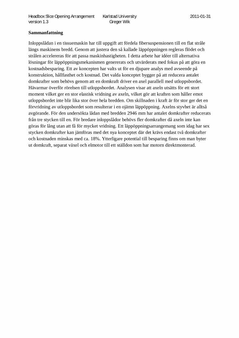
In the tissue paper machine a headbox distributes the fiber-water suspension over the width of the machine and it is accelerated when exiting through an oblong nozzle called slice opening. To adjust the flow to fit different machine speeds and different paper qualities, the slice opening is adjustable by means of a slice opening arrangement. The pressure inside the headbox is approximately 7bar and the area of the moving part is quite large, which means that the force exerted on the slice opening arrangement is high. The current arrangement is expensive and rather complicated, consisting of multiple mechanical jacks coupled by a transverse shaft and driven by a common gear and electric motor. The aim of this work is to find alternative solutions and to verify its structural integrity by finite element analysis. The current solution is seen in Figure 1.
Figure 1, Standard Headbox OptiFlo II TIS, 2946 mm
2 Aim and limitations The aim is to present an alternative solution for the slice opening arrangement that fulfills all requirements, but to a lower cost than today’s solution. This work is limited to the slice opening mechanism and precision adjustment with a possibility to make changes to the support beam and apron beam if necessary to fit the new mechanism. If the new mechanism is radically different from the old one, these changes can be rather extensive.

Headbox Slice Opening Arrangement Karlstad University 2011-01-31 version 1.3 Greger Wik
2
3 Method A sequential product development method was used with the following steps:
1. Identify customer needs 2. Determine criteria 3. Generate concepts 4. Concept rating, evaluation and elimination 5. Choose concept 6. Analysis and optimization 7. Final product specification (drawings etc.)
The methods used in the different steps are described below.
3.1 Identify Customer Needs and Determine Criteria By interviewing engineers, the current solution was analyzed regarding its function and drawbacks. From this, a list of demands and requests for the new solution was formulated. This list is the driving force for the next step where ideas for solutions are generated. The most important criteria is found in Table 1, Concept scoring matrix which is explained later in the text.
3.2 Concept Generation First the problem is decomposed into simpler sub problems and solutions for these are generated by brainstorming. As a second step, sub solutions are combined into concepts.
3.3 Concept Selection The different concepts are rated and given ranking by using a selection matrix following methods described by Ulrich and Eppinger (2008). The criteria evaluated are derived from the customer needs and the sub problems. Each concept is given a score between 1 and 5 for every criterion.
3.4 Mechanical design During concept generation and product specification 3d models and drawings are made using Catia V5
3.5 Finite Element Analysis This section of the text describes how the finite element analysis was done. Using Ansys software the slice opening arrangement was analyzed with certain interest in the amount of deformation and possible stress concentrations resulting from the pressurized fiber suspension. The main limiting factor is the elastic deformation, since the slice lip opening increases because of the pressure. It is also important to have an equal deformation over the width in order to have the same slice opening in the center as at the far end. Setting up the model in Ansys requires certain considerations mentioned in the paragraphs below.
3.5.1 Scope of model The pressurized fiber suspension causes elastic deformation of the whole structure of the headbox and the design of the slice opening arrangement play an important role in how this
Headbox Slice Opening Arrangement Karlstad University 2011-01-31 version 1.3 Greger Wik
3
deformation is distributed. Because of this the upper half of the headbox is included in the Ansys model, i.e. support beam and apron beam. In the first step the electric jack is not included in the model in order to only evaluate the elastic deformation of the shaft, arms and mounts.
3.5.2 Simplifications Holes, small chamfers and blends are removed in order to make the mesh simpler. The connecting rods between the apron beam and the crankshaft are modeled as springs. The springs are given properties such as spring constant and attachment points, but they don’t have a volume or geometry, and hence are not meshed. The spring constant is calculated from the Young’s Modulus. Due to symmetry only half of the headbox was analyzed.
Joints vs. body contact: By using Ansys joints instead of letting the solver evaluate the contact between meshes of the two parts a great deal of computer power is saved. Joints are used at the hinge between apron beam and support beam and at the bearings for the shaft. When using cylindrical joints there is a risk of adding stiffness to the structure, since in reality the hinge might be deformed during load and not perfectly cylindrical. A quick test was performed using no separation contact instead but it didn’t have any major effect on the result since the reference edge on the apron beam is some distance away from the hinge.
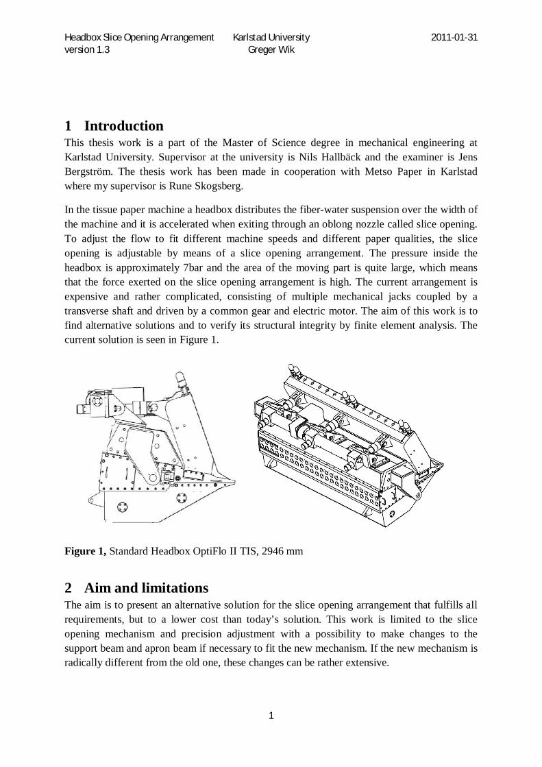
3.5.3 FEA considerations Hexahedral vs. Tetrahedral: As seen in Figure 2 it takes five 4-node tetrahedron elements to cover the same volume as one 8-node hexahedron element. If we add midside nodes the hexahedron element has 20 nodes while the tetrahedron has 8-nodes. For the five tetrahedral elements the total number of nodes is 26 because of node sharing between the elements. Wherever it is possible to use hexahedral element instead of tetrahedral, it means saving of computer power.
Figure 2, Hexahedron vs. Tetrahedron

Headbox Slice Opening Arrangement Karlstad University 2011-01-31 version 1.3 Greger Wik
4
Tetrahedrals are in general less accurate than hexahedrals when analyzing stress due to the fact that the tetrahedral shape is very stiff. Improved element formulation has however increased accuracy. (Donald, 2007) (sid203)
Solid elements vs. solid-shell v.s. shell elements: For flat plates (sweepable) with size considerably larger than the thickness, solid-shell elements have been used. SOLSH190 is a 3-D 8-Node Structural Solid Shell element in ANSYS. The eight nodes have three degrees of freedom each, namely the translations in x,y and z. This allows the solid shell element to be connected to ordinary solid elements without any particular measures. Total number of DOF’s is 24 for solid–shell and compared to 60 DOF’s for a 20-node solid element which has 3 DOF’s per node. An ordinary 4-node shell element has rotational DOF’s in addition to the translational, i.e. six DOF’s per node, 24 DOF’s in total. With a low number DOF’s and nodes, the shell element is often used as a simplification of thin plate structures where plane stress is assumed. The classic shell formulation is however not satisfying if fully three-dimensional material formulations are required to take the structural behavior adequately into account. (Swarze M, 2009). Although solid elements can handle 3-D stress states, they are found to be less accurate for shell like structures where the stress state can be overestimated and the deformation underestimated. (Swarze M, 2009) Solid-shell formulations is a way of utilizing the advantages of both shell and solid elements. Since the solid-shell element is three dimensional and the 3-D strain tensor and stress tensor are applied, any kind of general material law necessary for large deformations problems can be used. (M. Harnau, 2002) Figure 3 show how different element types are used. For instance is the shaft split into pieces and then rejoined in order to be able to sweep 20-node hexagonal elements where the shaft is smooth, but in the vicinity of the keyways tetrahedral elements is needed, since the geometry is not sweepable. You can also see that where solid hexagonal elements are used, minimum three elements are used through the thickness, compared to the plate in the bottom of the picture only has one element in the thickness of the plate. This is because solid-shell elements have been used.
Figure 3, Different element types in mesh

Headbox Slice Opening Arrangement Karlstad University 2011-01-31 version 1.3 Greger Wik
5
Since the support beam and apron beam are welded structures with lots of plates, it is of great importance to make a good meshing to keep the number of elements and nodes down. By specifying number of elements along edges in the areas of certain interest you can have a coarse mesh in general, but still have accuracy enough in critical areas.
In order to improve performance, the total number of elements was gradually reduced and the final model had a total of 42636 elements and 199223 nodes and an overview can be seen in Figure 4. The structure has a lot of internal stiffening plates not shown in the picture.
Figure 4, Entire model with mesh.
Meshing quality and element skewness: In areas where stress and strain is changing rapidly a finer mesh is needed, but the transition between the fine and coarse mesh must be gradual. If there is a sudden change in mesh size artificial stress concentrations can occur when FEM tries to interpolate displacements. (Donald, 2007) Depending on the geometry, chosen element type and size the elements might get distorted. This means that the element is skewed and the angles are deviating from the optimum shape. The degree of distortion can be displayed as skewness in statistics for the mesh in Ansys . Aspect ratio (length to width) above five should be avoided in critical areas, and best accuracy is achieved with aspect ratio below three. If a certain area needs to be improved, constraints can be changed or added to an edge, face or volume to specify the size or number of elements. Up to 10-15% of the elements can be allowed to be poorly shaped if they are not located in critical areas. (Donald, 2007) Multibody analysis – contact regions vs. matched nodes: To avoid the cumbersome work of matching nodes between parts, contact regions is a way of automatically connect parts with different mesh. There are different types like frictionless or no separation, but for the typical joint between two welded plates the contact is said to be bonded. After meshing, contacts can be generated automatically or manually and evaluated graphically where the contacts are displayed in different colors depending on how well the parts are bonded. How well the connection works depends on the distance between the nodes

Headbox Slice Opening Arrangement Karlstad University 2011-01-31 version 1.3 Greger Wik
6
to be connected. Without going to deep into the theory, the displacement of the two nodes relative to each other becomes difficult to evaluate if the distance is too far since the rest of the mesh needs to be allowed deform. If the mesh is to coarse the contact is displayed as sliding, which can be cured by refining the mesh in the area. Because the welded structure has a lot of internal plates, the number of contact definitions exceeded one hundred. Contact stress – avoiding stress singularities and importance of meshing: To have an accurate solution with body to body contact, a conforming mesh with matching nodes between the two parts is best. If stress concentrations arise the mesh is made finer in that area. Boundary Conditions and Loads: The support beam has fixed support at the row of bolts to the tube bank and at the back at the hose connection plate. The pressurized fiber suspension is in reality accelerating as the opening area decreases towards the slice lip tip. This causes the pressure to vary according to Bernoullis equation, resulting in a lower pressure at the tip, where the velocity is highest. In the Ansys model however, the pressure exerted on the apron beam is considered to be constant and evenly distributed over the whole area from the hinge to the tip of the lip. System requirements – memory allocation: A rule of thumb is that the memory requirement is 1GB/1 million DOF’s for out-of –core matrix calculation and 10GB/million DOF’s for in-core-mode. (source: Ansys Performance Guide) DOF is an abbreviation for Degrees Of Freedom, i.e. the number of unconstrained directions or rotations of a node. Out-of-core means that the factored matrix is held on disc, instead of RAM. For instance if you have a hexahedral solid element mesh with 400000 nodes, where each node has 3 DOF’s, the total number DOF’s in the model will be 1,2 million. This would require 1,2GB memory in the out-of-core mode and 12GB in the in-core-mode. By using a page file on the hard drive, complex problems can be solved on systems with limited memory, but page file usage increases the solving time. Linear v.s non-linear: Non-linear calculation can occur if non-linear material properties are used or if contact between two parts is specified as frictionless or rough. When non-linear contacts like these are used, the contact between two meshes needs to be evaluated during each calculation iteration, since the two parts are allowed to separate if there are tensile forces, but if it is compression the two meshes are not allowed to interfere. For the boundary conditions like supports, this also applies to the alternative “compression only”. If contact is stated to be bonded, nodes of the two parts are connected even if they don’t match perfectly. In this case a linear solution method can be used. For complex geometry with many parts, using bonded contact is a simplification which helps the solution to converge. It is important to keep in mind that stresses are not correct close to pins using bonded since this allows tensile stress normal to the contact surfaces. In reality you can only have compression between two surfaces. To have a correct analysis of the stresses close to a pin in a hole, frictionless or

Headbox Slice Opening Arrangement Karlstad University 2011-01-31 version 1.3 Greger Wik
7
rough should be used. To make this non-linear calculation converge the model can be reduced to only the lug and pin. It should be noted however that using bonded contact is perfectly correct in some cases such as welded plates, which can take both tensile and compression forces.
4 Results
4.1 Result from Concept Generation First the problem is decomposed into simpler sub problems and solutions for these are generated by brainstorming. As a second step, sub solutions are combined into concepts. The most interesting concepts are presented below.
4.1.1 Concept 1, Crankshaft A single central mechanical jack is attached to a lever mounted on a shaft with a number of shorter levers. The movement is transferred to the apron beam through arms with slide bearings in each end. These arms need to be designed as turnbuckles to allow adjustment to compensate for inaccuracies in the welded structure. Since the movement of the crank pin traces an arc, a minimum slice opening can be set to for instance 2 mm, by adjusting the arm lengths. This means that the slice lips cannot collide by mistake. If the crankshaft is turned beyond the minimum point, the slice opening will simply start to increase again. An alternative to adjustable arms is to have bolted mounts on the apron beam. The mounts can be adjusted to correct height either by machining or shims. The jack is attached to the longer lever at the position of the arrow marked Fj in Figure 5.
Figure 5, Concept 1, Crankshaft, v1
4.1.2 Concept 2, Electric Actuators Multiple electric actuators with integrated gear and motor are mounted along the width of the headbox between the support beam and the apron beam, working in the same manner as hydraulic cylinders would. The actuators need to be connected to a control system with
Fj Fj

Headbox Slice Opening Arrangement Karlstad University 2011-01-31 version 1.3 Greger Wik
8
position sensors to make sure they act synchronous. The mechanical design is simple and is limited to mounting lugs on the support beam and apron beam. Many actuator models on the market are lower capacity than today’s mechanical jacks and thus a larger number of them are needed to achieve the same force. There are however a few models for high loads such as the Swedrive X75. It utilizes a standard electric motor mounted on the side and is not quite as slim in its design as the smaller units. Different types of actuators are shown in Figure 6
Figure 6, Concept 2, Electric actuators
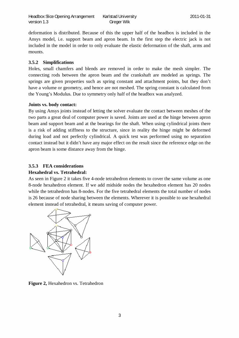
4.1.3 Concept 3, Gear Segment Gear segments are mounted on parts protruding from the apron beam and extending into the support beam. Driving gears placed inside the support beam could be driven by gear-motor units lowered into the support beam through openings on the top. The need of high torque and big gear box ratio probably means fitting inside the support beam difficult. An alternative solution is to mount all gears on a common shaft extending through the head box width and driven by a gearbox and motor mounted on the side of the headbox. Machining of bearing positions in the support beam for a long shaft is a difficult task that needs a clever solution, since machining the middle ones after welding is hardly possible. At least it is difficult and expensive. Since the driving gears cannot be made very small, a big reduction ratio is needed. The gear needs to be rotated less than half a turn to accommodate full opening to service position. This makes a lever and a mechanical jack (or electrical actuator) perhaps a better way to rotate the shaft than a gearbox and motor. The concept is shown in Figure 7.
Headbox Slice Opening Arrangement Karlstad University 2011-01-31 version 1.3 Greger Wik
9
Figure 7, Concept 3, gear segments
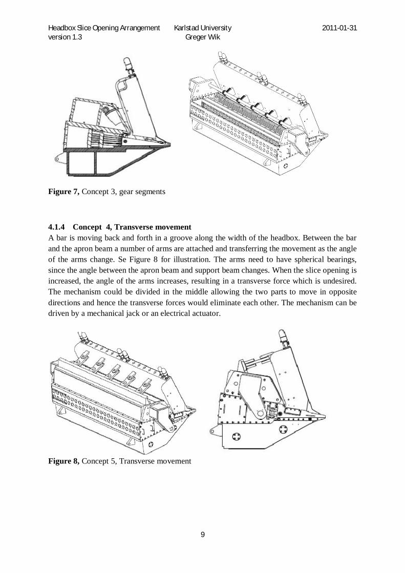
4.1.4 Concept 4, Transverse movement A bar is moving back and forth in a groove along the width of the headbox. Between the bar and the apron beam a number of arms are attached and transferring the movement as the angle of the arms change. Se Figure 8 for illustration. The arms need to have spherical bearings, since the angle between the apron beam and support beam changes. When the slice opening is increased, the angle of the arms increases, resulting in a transverse force which is undesired. The mechanism could be divided in the middle allowing the two parts to move in opposite directions and hence the transverse forces would eliminate each other. The mechanism can be driven by a mechanical jack or an electrical actuator.
Figure 8, Concept 5, Transverse movement

Headbox Slice Opening Arrangement Karlstad University 2011-01-31 version 1.3 Greger Wik
10
4.1.5 Concept 5, Scissor mechanism Multiple scissor mechanisms with common or separate drive unit is another concept. Two basic types of mechanisms are shown in Figure 9. If scissors of type A are mounted lying down with the screw in direction of the width, they have to have spherical bearings to allow the angle between the apron beam and support beam to change. Type B can be placed standing and is insensitive to the change of angle. The screw position is moving when using type B which complicates the use of a common drive unit. If the there are separate drive units for each scissor, they can be allowed to move along with the screw. Other solutions can involve left and right hand threads to make the screw to remain centered in the scissor mechanism.
Figure 9, Scissor mechanism
Type A Type B
fixed fixed
drive screw
drive screw

Headbox Slice Opening Arrangement Karlstad University 2011-01-31 version 1.3 Greger Wik
11
4.1.6 Concept 6, Precision Adjustment The precision adjustment mechanism could be modified with a long torque arm giving the same leverage as today’s solution, but without the extra triangular plate. See Figure 10 for illustration. The new solution has less moving parts and joints that could give excessive play. The torque arm could probably be angled more towards the roll than in the concept draft, and it wouldn’t necessarily need to be entirely straight, thus limiting the need of modification of the support beam. To make reading of the gauges easier they can be angled 45 degrees, or a different type with the face normal to the direction of movement can be used. This concept is separate from the slice opening arrangement and could probably be combined with other concepts.
Figure 10, Precision adjustment
4.2 Concept Selection -- Crankshaft Concept, the Chosen One. The ranking doesn’t present a clear winner since three of the concepts have similar score in the matrix. The scoring matrix can be found in Table 1. There are however other more fussy criteria not included in the matrix such as customer acceptance and technology uncertainties. Reliability is important since the operating cost for a paper machine is high and if the machine stops due to mechanical problems, lots of money is lost. Because of this, proven technical solutions are preferred. This eliminates some of the more inventive solutions. Other concepts might involve some technical problem where a solution is not apparent and are thus eliminated due to this uncertainty.
Taking the considerations above in account, the crankshaft concept is selected. This was a decision made in a meeting with participating engineers from departments KCR and KSA.
If the dial indicator is hard to read, the face can be upwards instead.
Fewer joints give better precision.
The support beam can be made thicker than shown in the figure for better stiffness.

Headbox Slice Opening Arrangement Karlstad University 2011-01-31 version 1.3 Greger Wik
12
Table 1, Concept scoring matrix
Concept 1, Crankshaft 2, Actuators 3, Gear
segments 4, Transverse 5, Sax 6, Fine tuning
7, Current solution
Criterion nr.
Wei
ght
dem
and
Poin
ts
Wei
ghte
d Po
ints
Poin
ts
Wei
ghte
d Po
ints
Poin
ts
Wei
ghte
d Po
ints
Poin
ts
Wei
ghte
d Po
ints
Poin
ts
Wei
ghte
d Po
ints
Poin
ts
Wei
ghte
d Po
ints
Poin
ts
Wei
ghte
d Po
ints
1 Free setting of slice opening Dmd OK OK OK OK OK OK OK 2 Possible to fine tune slice opening Dmd OK OK OK OK OK OK OK 3 Possible to open to service position. Dmd OK OK OK OK OK OK OK 4 Withstand forces from pressurized fiber suspension 5 4 4 5 5,0 2 2,0 4 4,0 4 4,0 5 4 4 5 Quick opening to service position. 4 4 3,2 3 2,4 3 2,4 4 3,2 4 3,2 --- 3 2,4 6 Powered by electricity. Dmd OK OK OK OK OK OK OK 7 Mechanical stop 4 5 4 2 1,6 2 1,6 5 4,0 3 2,4 --- 1 0,8 8 End position switch. 4 OK OK OK OK OK --- OK 9 Self-braking mechanism Dmd
10 Corrosion resistant 5 5 5 3 3,0 2 2,0 5 5,0 5 5,0 5 5 5 11 Easy to clean. 3 3 1,8 3 1,8 5 3,0 3 1,8 2 1,2 --- 3 1,8 12 Low maintenance 4 3 2,4 4 3,2 1 0,8 3 2,4 1 0,8 5 5 4 13 Low material usage 3 3 1,8 5 3,0 4 2,4 3 1,8 3 1,8 --- 3 1,8 14 Easy to weld. 3 2 1,2 5 3,0 3 1,8 3 1,8 3 1,8 --- 3 1,8 15 Easy to assemble. 1 3 0,6 5 1,0 3 0,6 4 0,8 2 0,4 5 3 0,6 16 Total cost. 4 3 2,4 3 2,4 3 2,4 3 2,4 3 2,4 2 1,6 17 Even distribution of force. 4 3 2,4 3 2,4 3 2,4 3 2,4 3 2,4 2 1,6 18 Minimize play in mechanism 4 4 3,2 5 4,0 3 2,4 3 2,4 2 1,6 3 2,4 19 Safe with minimum need of protection 5 3 3 4 4,0 5 5,0 3 3,0 2 2,0 3 3 20 Reliability of operation 5 4 4 3 3,0 3 3,0 4 4,0 3 3,0 4 4 21 IP class 66 Dmd OK ? OK OK OK OK 22 High accuracy 5 4 4 4 4,0 3 3,0 4 4,0 3 3,0 4 4
Sum 43 43,8 34,8 43,0 35,0 38,8

Headbox Slice Opening Arrangement Karlstad University 2011-01-31 version 1.3 Greger Wik
13
4.3 Mechanical design The design of the chosen crankshaft concept was developed from the initial concept sketch to be more compact to reduce the outer dimensions of the headbox. To minimize cost, standard parts are chosen instead of own design where possible. For instance the connecting rods were designed with standard spherical rod ends as shown in Figure 11.The rod ends are right hand and left hand threaded to make the connecting rod work as a turnbuckle. To reduce material cost some design considerations were made. For instance two parallel lugs would provide a better force distribution where the arms are connected to the apron beam, but a single lug was chosen to save material. The bending and twisting force resulting from this decision is analyzed in a later stage. The number of connecting rods to the apron beam is increased compared to the number of jacks in the current solution in order to have a more evenly distributed force. This gives an opportunity for further material savings by reducing the number of stiffeners in the apron beam. If the forces in the different connecting rods are not equal, the apron beam needs to be rigid to resist twisting. Optimizing the apron beam is however not covered in this work.
The lugs welded to the apron beam needs to have the hole machined prior to welding because of limitations in the manufacturing equipment. This however means that narrow tolerance of the hole is difficult to achieve since it is deformed from the heat during welding. It would be better to use bolts, because then a wider tolerance on the hole diameter is allowed, compared to a cylindrical pin which require a narrow tolerance on the hole diameter.
The main features of the different design versions are listed in Table 2 and the main parts are shown in Figure 11.
Table 2, Design versions
Design version
Shaft Dy
Shaft Di
Apron Beam Height
Connecting Rod
Lug on Apron Beam
V1 --- 0 Low Std Rod Ends Single w. pin on one side V2 60 71 Low Std Rod Ends Single w. pin on one side V3 120/140 80 Low Std Rod Ends Single w. pin on one side V4 140 80 High Std Rod Ends Single w. pin on one side V5 140 High Double Rod
Ends Single symmetric w. pin on both sides
V6 140 Low Double Rod Ends
Single symmetric w. pin on both sides

Headbox Slice Opening Arrangement Karlstad University 2011-01-31 version 1.3 Greger Wik
14
Figure 11, Main parts of mechanism.
To better understand the results later in the report, the different design versions are described below.
4.3.1 Design v1 Design v1 is the first preliminary design from the concept generation shown in Figure 5. Overall dimensions where too big and bulky and the special designed turnbuckle connecting rods seemed expensive to manufacture.
4.3.2 Design v2 Design v2 was a slim, compact design made to reduce outer dimensions. See Figure 12 for basic design. The height of the apron beam was reduced by 239 mm to allow welded lugs on top. The reduced height was also made to reduce material use in the apron beam. The shaft was only 60 mm (solid) and the seven connecting rods had M30 rod ends. However it turned out after hand calculations, that the shaft was going to have too much torsional deformation. The choice to have seven connecting rods resulted in three rods on one side of the mechanical jack and four on the other side which, in combination with the mentioned torsional deformation, gave uneven support to the apron beam. Thus the design had to be revised.
Pin
Rod End
Arm
Shaft
Rod End
Connecting Rod
Lug

Headbox Slice Opening Arrangement Karlstad University 2011-01-31 version 1.3 Greger Wik
15
Figure 12, design v2
4.3.3 Design v3 Design v3 uses a hollow shaft, dy=120 mm di=71 mm, and six connecting rods with M36 rod ends. Height of apron beam is reduced by 239 mm (equal to v2). As a test to reduce torsional deformation, the shaft was increased to dy=140 mm and di=80 mm. This larger diameter would however require a different type of rod ends on the connecting rods to fit. The shaft turns 28 degrees to give a 20 mm slice opening, and 72 degrees at 90 mm service opening. Figure 13 shows the v3 design where lower apron beam is clearly seen as the micro adjusters are left at the original height in this picture.
Figure 13, design v3

Headbox Slice Opening Arrangement Karlstad University 2011-01-31 version 1.3 Greger Wik
16
4.3.4 Design v4 Design v4 uses the 140 mm shaft, but has the original height of apron beam in order to reduce the forces in the connecting rods. As the pins in the lugs on the apron beam is further away from the hinge line of the apron beam, the distance of movement is increased, which in turn requires a larger angle of rotation of the shaft to get the same slice opening. At 20 mm the rotation of the shaft is 32 degrees with this design, and 84 degrees at 90 mm service opening. Figure 14 shows design 4 at 3 mm and 20 mm slice opening.
Figure 14, design v4

Headbox Slice Opening Arrangement Karlstad University 2011-01-31 version 1.3 Greger Wik
17
4.3.5 Design v5 To avoid the movement from twisting of the single lugs, a test was made with a pin protruding through the lug on both sides. See Figure 15 for illustration. The connecting rod needs to be designed as a fork to apply force on both sides of the lug. The arm on the shaft was made in a similar way, but it should be noted that the arm probably needs to be thicker to accommodate a long enough key to transfer the torque. Apart from the arms and lugs the geometry is the same as in design v4.
Figure 15, Design v5
Figure 16, Connecting rod, design v5 and v6
Headbox Slice Opening Arrangement Karlstad University 2011-01-31 version 1.3 Greger Wik
18
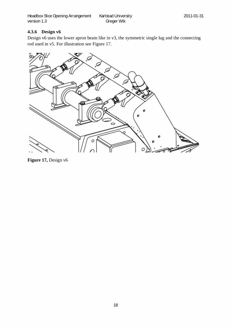
4.3.6 Design v6 Design v6 uses the lower apron beam like in v3, the symmetric single lug and the connecting rod used in v5. For illustration see Figure 17.
Figure 17, Design v6

Headbox Slice Opening Arrangement Karlstad University 2011-01-31 version 1.3 Greger Wik
19
4.4 Calculations Simple hand calculations were made to investigate the forces in the arms and the amount of torsion in the shaft. The calculated compression force in the arms agrees well with the average force when analyzing with Ansys, which is shown in Table 7 in the section with results from FEA. The torsion of the shaft was calculated assuming that the force was applied to the arms on the shaft in the angle at which 20 mm slice opening is achieved. In this first check with hand calculations, the stiffness of the apron beam was not considered. It was found that the angular difference between two adjacent arms is very big. In reality however, the stiffness of the apron beam makes the movement of the arms more unison, and instead the force in the arms is differentiated, which is confirmed by the FEA later in the text. All results are shown in Table 5.
Table 3, Material properties
E GPa Young’s Modulus 200 G GPa Shear modulus 77 Poisson’s ratio 0,3
Table 4, Load
Fiber suspension pressure, (MPa) 0,7 Headbox width, ( mm) 2946 Hinge to slice lip tip, ( mm), R5 666,5 Force from pressure, Fp (N) 1,374x106
Figure 18, Parameter labels

Headbox Slice Opening Arrangement Karlstad University 2011-01-31 version 1.3 Greger Wik
20
Figure 19, Parameter labels
Total force from pressure, Fp, in
Table 4 is simply the pressure times the area. If this force is considered to be applied to the apron beam at half the distance, R5, between the hinge and the lip tip, we have the equilibrium of moments in eqn. 1 from which we can calculate the total force on the top of the apron beam, Fr. The needed force per connecting rod, Fc, is found by dividing Fr with the number of connecting rods. The parameters R1, R2 etc are explained in Figure 18.
1 = (eqn.1)
The total torque needed on the shaft to keep the apron beam stationary is the force times lever arm length as in eqn2.
3 (eqn.2)
To find the needed jack force the total torque is divided by the length of the jack arm using eqn. 3
= (eqn.3)
To calculate the twisting of the shaft between two certain points the torque Mv1, Mv2 etc is calculated using eqn.4 where n1, n2 is the number of connecting rods attached further out on
Fc
Fc
Fc
Fc
Fc
Fc
3
2
1
1
2
FJ
Mv1 1
1 Mv2
2
2
3 Mv3
3
3

Headbox Slice Opening Arrangement Karlstad University 2011-01-31 version 1.3 Greger Wik
21
the shaft. For instance if twisting between the jack arm and the first arm on the shaft is to be calculated, the shaft is subjected to a torque from three connecting rods (n1=3) if the total number of connecting rods is six.
3 (eqn.4)
The polar moment of inertia for a hollow shaft is calculated using eqn.5.
= ) (eqn.5)
The twisting angle of the shaft between two arms is calculated using eqn.6 where G is the shear modulus from Table 3 and L is the length of the part of the shaft being analyzed. For instance if the twisting of the shaft between the jack arm and the arm labeled 1 in Figure 19 is to be calculated, L = Ls/2. For twisting between arm 1 and 2 the parameter L = Ls.
= (eqn.6)
The arm spacing, Ls, is found using eqn.7, where Lw is the total width of the headbox.
( 1) + 2 0,4036 (eqn.7)
The shear stress is calculated using eqn.8 where Wv is the torsional resisting moment according to eqn.9
= (eqn.8)
= (eqn.9)
All results are listed in Table 5.

Headbox Slice Opening Arrangement Karlstad University 2011-01-31 version 1.3 Greger Wik
22
Table 5, Calculation of twisting angle and max shear stress.
Design version V2 V3 V3 V4 Dy mm Outer diameter shaft 60 120 140 140 Di mm Inner diameter shaft 0 71 80 R1 mm Apron beam height,
hinge to pin distance 773,5 673,1 673,1 773,5
R2 mm Shaft center to pin distance 90 90 90 90 deg Angle of shaft at 20 mm slice opening 30,5 28,7 28,7 30,5
R3 mm Shaft center to pin distance perpendicular to force direction
67,2 65,2 65,2 67,2
Fr kN Total force top of apron beam 592 680 680 592 n Pcs Number of connecting rods 7 6 6 6 Fc kN Force per connecting rod 84,6 113 113 98,7 Mvtot Nm
x1000 Total Torque on shaft 39,7 44,3 44,3 39,7
R4 mm Jack arm length, shaft center to pin 180 180 180 180 Fj kN Needed Jack force 221 246 246 221 Lw mm Width of headbox 2946 2946 2946 2946 Ls mm Spacing between connecting rods 433 507 507 507 Iv m4 x10-
6 Polar moment of inertia 1,27 17,9 33,7 33,7
Wv m3 x10-
6 Torsional Resisting Moment 42,4 298 481 481
Mv1 Nm x1000
Torque exerted on shaft from all connecting rods on one side of jack arm.
22,7 22,2 22,2 19,9
1 rad Angle of twist between jack arm and connecting rod 1 0,0505 0,00409 0,00217 0,00195
1 deg Angle of twist between jack arm and connecting rod 1
2,90 0,234 0,125 0,112
1 MPa Max Shear stress from twisting, between jack arm and connecting rod 1
535 74,5 46,2 41,4
Mv2 Nm x1000
Torque exerted on shaft from connecting rods 2 and 3 (and 4)
17,0 14,8 14,8 13,2
2 rad Angle of twist between connecting rod 1 and 2 0,0753 0,00544 0,00289 0,00258
2 deg Angle of twist between connecting rod 1 and 2 4,3 0,312 0,166 0,148
2 MPa Max Shear stress from twisting 403 49,7 30,8 27,4
Mv3 Nm x1000
Torque exerted on shaft from connecting rod 3 (and 4) 11,4 7,37 7,37 6,63
3 rad Angle of twist between connecting rod 2 and 3 0,0358 0,00271 0,00144 0,00130
3 deg Angle of twist between connecting rod 2 and 3 2,05 0,155 0,0825 0,0745
3 MPa Max Shear stress from twisting 270 24,7 15,3 13,8 Mv4 Nm
x1000 Torque exerted on shaft from connecting rod 4 5,69 N/A N/A N/A
4 rad Angle of twist between connecting rod 3 and 4 0,0252 N/A N/A N/A
4 deg Angle of twist between connecting rod 3 and 4 1,444 N/A N/A N/A
4 MPa Max Shear stress from twisting 134 N/A N/A N/A

Headbox Slice Opening Arrangement Karlstad University 2011-01-31 version 1.3 Greger Wik
23
4.5 Jack size The needed jack force is approximately 125 kN when using a jack arm with 180 mm radius from shaft center to pin center and the smaller arm with 105 mm radius. The 200kN jack which is used today can be used, but using a 5ton jack instead would lower the cost significantly. With 80% of the rated load the maximum force is 40kN which calls for a longer jack arm radius of 562.5 mm to achieve the same torque on the shaft. The needed stroke length is 272 mm at 20 mm opening and 661 mm at service opening. The needed arm length and stroke length makes it difficult to mount the jack on top of the headbox without extending backwards, which should be avoided because of interference with other parts of the paper machine.. To make it work, the design of the slice opening arrangement needs to be changed somehow, to mount the jack further forward.
Table 6, Arm Radius vs. Jack Stroke and Force
Jack Arm Radius mm
Slice Opening mm
Shaft Angle degrees
Jack Stroke mm
Jack Force kN
180 20 28 87 125 180 90 72 211 - 562,5 20 28 272 40 562,5 90 72 661 -
Figure 20, Swedrive 75kN and 250kN actuator approximate size compared to current 20ton Swedrive jack.
4.6 Results from Finite Element Analysis The v3 design evaluated with Ansys confirms that twisting of the shaft is a major problem with this design. When the shaft experience torsional elastic deformation, the resulting force in the connecting rods is differentiated and the support to the apron beam is weaker at the sides than in the center. This causes an unequal deformation of the apron beam and a larger slice opening at the sides than in the center. As an effort to decrease the torsional deformation

Headbox Slice Opening Arrangement Karlstad University 2011-01-31 version 1.3 Greger Wik
24
of the shaft, the outer diameter was increased from 120 mm to 140 mm and the inner diameter from 71 to 80 mm. Movement of the apron beam is reduced by approximately 0.2 mm and the difference between the center and the far side is reduced from 0,29 to 0,13 mm. The movement showed in Figure 21 is at the edge shown in Figure 22 below. The force in the connecting rods is varying from the center to the far end with a maximum of 140 kN in the connecting rod closest to the center and minimum of 95 kN in the one farthest from the center, but with the larger diameter shaft the forces are between 132 kN and 99 kN. See Table 7 below.
Figure 21, movement on top of apron beam at edge near precision adjusters
Figure 22, movement at edge on top of apron beam
0
0,2
0,4
0,6
0,8
1
1,2
1,4
1,6
1,8
0 62 122
182
242
302
362
421
481
541
601
661
724
784
844
904
964
1024
1084
1144
1204
1269
1330
1390
1473
Tota
l Def
orm
atio
n in
Z-d
irec
tion
(m
m)
Sideways Position (mm)(Zero at center of headbox)
v3 Dy120 Di71
v3 Dy140 Di80
Difference , center to far side=0,29mm
Difference , center to far side=0,135mm

Headbox Slice Opening Arrangement Karlstad University 2011-01-31 version 1.3 Greger Wik
25
Because the Ansys model is simplified and does not include the micro adjusters, the stiffness of the lip is not correct and hence the resulting deformation at the tip of the lips is not relevant. For comparison between different designs, the edge at the joint between the lip and the apron beam is used as a reference. This edge is located approximately half way between the hinge and the tip of the lips, see Figure 24 below, meaning that the slice opening difference will be approximately twice the movement shown in Figure 23 below. An interesting fact is that at this reference edge, the difference between the center (zero position in the diagram) and the far end is not as big as in Figure 21 . The smallest diameter shaft (v3 120 mm) is clearly weaker further to the side, but the other ones are not. This indicates that the bottom plate of the apron beam is rather stiff, but the upper part is more flexible.
Figure 23, Chart of movement in local Z-direction (upward) at the edge of joint between apron beam and lip.
0
0,2
0,4
0,6
0,8
1
1,2
1,4
0 500 1000 1500 2000 2500 3000 3500 4000
Mov
emen
t (m
m)
Position along edge (mm) (zero at center of headbox)
v4 Dy140 Di80
v3 Dy140 Di 80
v3 Dy120 Di71
Original mechanism (different ansys model)
v5 symmetric lug connection
v6 low apron beam symmetric lug connection

Headbox Slice Opening Arrangement Karlstad University 2011-01-31 version 1.3 Greger Wik
26
Figure 24, edge of joint between apron beam and lip
In design v3 and v4 the lugs welded on top of the apron beam is not aligned with the stiffeners inside the apron beam, which means that the plate is allowed to bend and deflect when force is applied to the lug. This can be seen in the diagram in Figure 26 as the variation between high and low points of the curve. At the position of each lug there is a dip in the curve, corresponding to the deflection of the plate. Note that the overall level of the curve includes the movement of the whole apron beam. To minimize the total deformation of the slice opening mechanism this deflection should be avoided by coordinating position of lugs with the stiffeners.
Figure 25, Deformation of apron beam at edge near lugs

Headbox Slice Opening Arrangement Karlstad University 2011-01-31 version 1.3 Greger Wik
27
Figure 26, Deformation of apron beam along edge close to lugs
Design v4 showed a similar amount of deformation (or slightly higher) at the edge shown in Figure 24 although it was expected to decrease. The longer leverage with original height of the apron beam gives lower forces in the connecting rods, and thus less twisting of the shaft and less movement of the arms, which in turn would give less deformation of the apron beam. See Table 7 for deformation results.
Table 7, Comparison of forces and deformation between different designs.
V3 full assy Dy120 Di 71
V3 full assy Dy140 Di80
Fixed shaft and arms v3
V4 full assy Dy140 Di80
Only apron beam v3
Only apron beam v4
Max arm movement ( mm)
2.15 1.44 N/A 1.29
Max movement at edge at joint between lip and apron beam.
1.22 1.07 0.64 1.10 0.46 0.42
Force in connecting rod 1 (kN)
140 133 113 114
Force in connecting rod 2 (kN)
101 104 108 89
Force in connecting rod 3 (kN)
94 99 118 84
Average Force 112 112 113 96 Needed jack force (kN) 124 126 N/A 119
0
0,2
0,4
0,6
0,8
1
1,2
0 62 122
182
242
302
362
421
481
541
601
661
724
784
844
904
964
1024
1084
1144
1204
1269
1330
1390
1473
Tota
l Def
orm
atio
n in
Z-d
irec
tion
(mm
)
Sideways Position (mm)(Zero at center of headbox)
v3 dy120 di71v3 dy140 di80

Headbox Slice Opening Arrangement Karlstad University 2011-01-31 version 1.3 Greger Wik
28
Since the result for v4 wasn’t the expected, the apron beam was investigated more thoroughly and it was found that the area near the hinge was subjected to significant bending as shown in Figure 27 and Figure 28 below. When only the apron beam was analyzed and the pins in the apron beam fixed to prevent it from rotating, the deformation at the edge at the joint between the lip and the apron beam was 0.4 mm which corresponds to approximately the double amount of change in lip opening. As a quick test, 5 mm extra material thickness was added to the area near the hinge which improved stiffness somewhat, but moving the hinge closer to the back plate of the apron beam would be the best. When the full assembly was analyzed the deformation was 1.1 mm. This bending occurs in both the v3 and the v4 design, but since the angle of the connecting rods are different, v4 has a resulting force upwards which probably makes the bending worse when the full assembly is evaluated. A lower attachment point for the connecting rod is better in this aspect, but on the other hand it gives higher forces resulting in more twist of the shaft. See Figure 29 for deformation in the local z-direction (upward) along the edge displayed in Figure 28. This is an edge on the symmetry plane of the Ansys model in the center of the headbox and thus not a real edge.
Figure 27, Deformation of apron beam, (increased deformation scale)

Headbox Slice Opening Arrangement Karlstad University 2011-01-31 version 1.3 Greger Wik
29
Figure 28, deformation in local Z-direction (upward) along edge of apron beam near hinge. (increased deformation scale)
Figure 29, Chart over deformation of apron beam, along edge shown in Figure 28 above.
In Figure 29 the curves for the whole assembly start with approx 0,2 mm deformation near the hinge. This is also confirmed in Figure 30, meaning that the pressure causes deformation of the support beam.
0,00
0,20
0,40
0,60
0,80
1,00
1,20
0 50 100 150 200 250 300 350
Def
orm
atio
n (m
m)
Position(mm) (zero close to hinge)
Only Apron Beam v4 ADDED MTRL
Only Apron Beam STD THICKNESS
Full Assy v4

Headbox Slice Opening Arrangement Karlstad University 2011-01-31 version 1.3 Greger Wik
30
Figure 30, Movement of Hinge
The twisting of the shaft gives elastic deformation, i.e. the stress levels are well below the yield point with shear stress approximately 100 MPa and von Mises stress below 150 MPa in areas not close to any keyway. See Figure 31 and Figure 32 for stress plots. Design v6 uses a thinner plate for the arms on the shaft which means a rather short key, which in turn gives stress concentrations along the edge of the keyway. The stress level is not alarming, but a finer mesh in the area of the keyway could be used to investigate this more thoroughly.
Figure 31, Shaft Maximum Shear Stress

Headbox Slice Opening Arrangement Karlstad University 2011-01-31 version 1.3 Greger Wik
31
Figure 32, Shaft von Mises Stress

Headbox Slice Opening Arrangement Karlstad University 2011-01-31 version 1.3 Greger Wik
32
Stress analysis of arms and lugs shows that the economical choice to have single lugs causes uneven stress distribution in the hole for the pin, with stress concentration at the edge on the opposite side from the applied force. The pins become somewhat tilted in the holes , see Figure 33, and also bent which makes this even worse. The stresses are much higher than tolerable, see Figure 34, and an area with high stress stretches over several elements of the mesh. No effort has been made to refine the mesh and fine tune the model to have precise stress levels from Ansys since the level is obviously too high. The lugs and arms were evaluated using a worst case scenario with a force of 140kN as compared to the average force in the connecting rods 112kN. Figure 35 shows minimum principal stress which indicates the compression from the contact pressure from the pin. Figure 36 shows maximum principal stress which indicates the tensile stress in the lug. Although double lugs is the conventional way to design similar parts, the aim of this project is cost reduction, and that’s why the possibility to use single lugs is investigated.
Figure 33, Single lug and pin deformation at 140kN

Headbox Slice Opening Arrangement Karlstad University 2011-01-31 version 1.3 Greger Wik
33
Figure 34, Single lug von Mises stress, 140kN
Figure 35, Minimum Principal Stress, Lug 140kN

Headbox Slice Opening Arrangement Karlstad University 2011-01-31 version 1.3 Greger Wik
34
Figure 36, Maximum Principal Stress, Lug 140kN

Headbox Slice Opening Arrangement Karlstad University 2011-01-31 version 1.3 Greger Wik
35
To simulate double lugs a symmetry boundary condition was set on the end of the pin and the force reduced to half. The results shown in Figure 37 and Figure 38 show that both stress and deformation is within the tolerable range. It also shows that the pin is more deformed in the middle than at the ends. Due to this bending of the pin there is a stress concentration on the edge of the hole. Larger pin diameter would reduce the stress further. Double lugs are the best option from a strength point of view, but not from a cost savings point of view.
Figure 37, Double lugs von Mises stress
Figure 38, Double Lugs deformation

Headbox Slice Opening Arrangement Karlstad University 2011-01-31 version 1.3 Greger Wik
36
In another attempt to use single lugs due to cost reduction, a model was made with the pin extending on both sides to have a symmetric distribution of the load. Only half of it needs to be modeled in Ansys when using symmetry boundary conditions in the center of the plate. A different type of connecting rod is needed, see Figure 16 above for illustration. The stresses and deformations are much lower compared to the single lug with load applied on only one side, but still the pin is bent and the whole lug has a deformation of 0.1 mm as can be seen in Figure 39 and Figure 40. There are also high stresses on the edge of the hole as shown in Figure 41. Larger diameter of the pin and greater thickness of the lug is probably the remedy for this.
Figure 39, Deformation of single lug with pin protruding on both sides. Symmetric load.

Headbox Slice Opening Arrangement Karlstad University 2011-01-31 version 1.3 Greger Wik
37
Figure 40, Deformation of single lug with pin protruding on both sides. Symmetric load. Half model in Ansys
Figure 41, Von Mises stress of single lug with pin protruding on both sides. Symmetric load. Half thickness shown

Headbox Slice Opening Arrangement Karlstad University 2011-01-31 version 1.3 Greger Wik
38
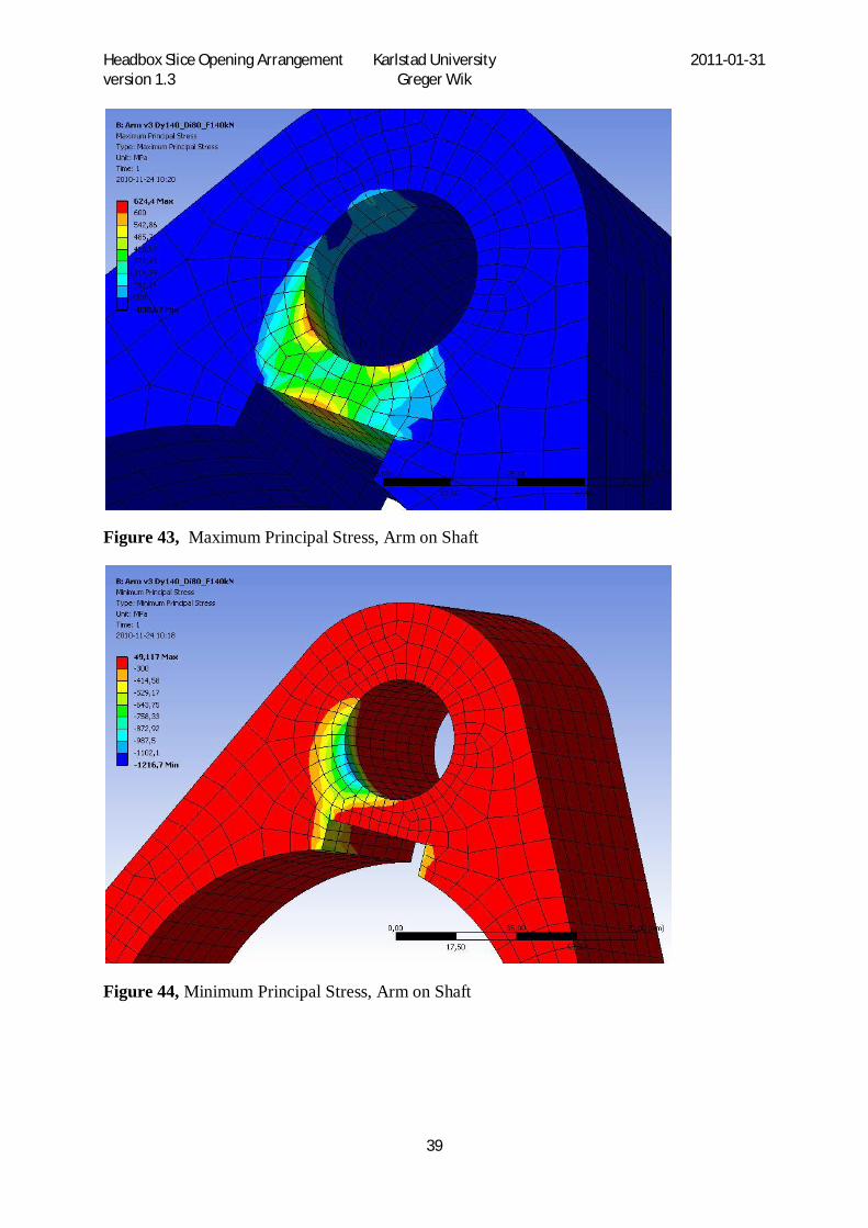
The arms on the shaft are analyzed in Ansys with certain attention to the area close to the keyway and the hole for the pin. It can be seen in Figure 42, Figure 43 and Figure 44 that also these arms suffer from the pin being angled when the connecting rod is attached on only one side, resulting in stress concentrations on the edge of the hole. A remedy for this would be to have a symmetrical connection to the connecting rod as investigated for the lugs on the apron beam. It can also be seen that the keyway should be moved away from the hole to avoid high stresses.
Figure 42, von Mises stress, Arm on shaft
Headbox Slice Opening Arrangement Karlstad University 2011-01-31 version 1.3 Greger Wik
39
Figure 43, Maximum Principal Stress, Arm on Shaft
Figure 44, Minimum Principal Stress, Arm on Shaft

Headbox Slice Opening Arrangement Karlstad University 2011-01-31 version 1.3 Greger Wik
40
4.7 Cost The cost for the new solution of design v6 is estimated using quotes based on preliminary drawings of the parts. The full detailed cost calculation is however not included in this report in order not to reveal specific costs which is classified by Metso.
The cost for the new solution is approximately 18% lower than for the current solution.
The single mechanical jack is assumed to be similar to the center one used today, including the motor and the gear assembly. Brackets and lugs have to be changed to fit the new solution, but those changes are considered not to affect the cost of the jack assembly. The lower height of the apron beam in version 3 and 6 means material and cost savings. The shaft is the most expensive part of the new solution and it represents approximately 20% of the cost of the whole mechanism.
The cost of the new solution was compared to the current one by using the actual cost of the entire element THB610 in a previous order. The headbox used in the development of the new solution was quite narrow and the previous order was almost twice as wide. Since the shaft can’t be made to long because of the twisting, the cost for the new solution is simply doubled as if two identical mechanisms are mounted side by side. This means that in the cost two motors and two gears are included.
Further savings are possible if the type of jack is changed to an actuator and thus eliminating the need for a separate gear and also the jack holder (plate with lugs) is no longer needed since the actuator has built in lugs in each end. Using a 25 ton actuator instead of a motor, gear and jack is approximately 35% cheaper. If a longer lever arm is used to reduce the needed force, a cheaper 7.5 ton actuator can be used. Note that the actuators are not made from stainless steel as the 20 ton jack which might make the comparison unfair.

Headbox Slice Opening Arrangement Karlstad University 2011-01-31 version 1.3 Greger Wik
41
5 Discussion The criterion to withstand 7 bar pressure in the whole range from 3 mm to 20 mm slice opening is extra tough to comply to since the torque on the shaft is higher at increasing slice opening. The current slice opening arrangement is not sensitive to the amount of slice opening, and thus the comparison is a little bit unfair. There have been discussions during this work if this criterion is realistic or not, since none of today’s headboxes have full pressure at such large slice openings. Nominal slice opening is usually 11 mm at which the torque and the twisting of the shaft would be less.
To have a common mechanism for service opening and operational slice opening eliminates some of the more compact solutions because of the need of long stroke length. If 0-25 mm slice opening was enough, a more compact and simple solution would be possible, but on the other hand a second separate mechanism is needed for service opening, which probably would eliminate the cost saving.
5.1 Future work To have an even distribution of support to the apron beam, the shaft needs to be as rigid as possible, but what is the upper limit for the shaft diameter?
If the current mechanical jack and motor assembly are to be used, the brackets on the support beam needs to be adapted to fit the slightly different position.
It would be nice to use a McGregor electric actuator instead of separate motor and gear. The McGregor unit is however considerably longer. Can the design be changed to accommodate this unit?
A smaller 5ton jack can be used if combined with a longer jack arm which results in a longer stroke. Can the design be changed to fit this longer stroke?
Single lugs welded onto the apron beam could be used if force is applied symmetrically on a pin extending on both sides, but the dimensions of the lug and pin diameter needs to be increased. A bushing (possibly DevaTex) is needed in the lug hole to allow smooth movement of the pin if connecting rods like in the v5 and v6 design are used.
The arms are locked in position relative to the shaft by means of a key. The key dimensions need to be chosen to withstand the torque and, if possible, following key standards. The position of the keyway in the arm needs to be moved away from the pin hole and the stress distribution should be further investigated.
How can this concept be applied to wider headboxes? Due to the shaft twisting issue it’s probably not possible to use only one jack on headboxes between 5-8 meters wide. One possibility is to simply duplicate the mechanism and use two mechanical jacks with separate shafts. This needs further investigation.
Using multiple electric actuators would be interesting to investigate as future work because of the simple mechanical design. In this case the cost of the actuators is the critical point rather

Headbox Slice Opening Arrangement Karlstad University 2011-01-31 version 1.3 Greger Wik
42
than the cost of the manufactured parts. A comparison between different brands, types, sizes and number of actuators needed should be made. Control system and sensors for synchronous operation is another topic for investigation.
6 Conclusion The crankshaft design v6 is the recommended one. It has a lower apron beam and single lugs with symmetric connecting rods. Given the design criterion to withstand 7 bar in the range 3 mm to 20 mm slice opening, the crankshaft design is weaker than the current slice opening arrangement. The design can be made stiffer by increasing the shaft diameter and increase dimensions of lugs and pins. If the design criterion is changed to a pressure load closer to actual operational pressure and slice opening, the comparison might be more positive for the crankshaft concept.
A headbox which as standard has six jacks can suffice with two jacks with the crankshaft solution and the cost is reduced by approximately 18%.
7 Acknowledgements I would like to express my gratitude to my supervisors Rune Skogsberg and Jonas Wall at Metso Paper for their good support and guidance. Janne Paulsson and Jonas Cederlöf also deserve acknowledgement for being most helpful and sharing their knowledge in FEA. Many thanks to Nils Hallbäck at Karlstad University for his prompt and detailed feedback on the report.
8 Works Cited Donald, B. J. (2007). Practical Stress Analysis with Finite Elements. Dublin, Ireland: Glasnevin Publishing.
K.T. Ulrich, S. E. (2008). Product Design and Development. New York: McGraw Hill.
M. Harnau, K. S. (2002). About linear and quadratic Solid-Shell elements at large deformations. Karlsruhe, Germany: Pergamon.
Swarze M, I. V. (2009). Sheet metal forming and springback simulation by means of a new reduced integration solid-shell finite element technology. Braunschweig , Germany: Elsevier.