
Head and Neck Lymph Node Region Delineation with Auto-segmentation and Image Registration
49
1 Head and Neck Lymph Node Head and Neck Lymph Node Region Delineation with Region Delineation with Auto-segmentation and Auto-segmentation and Image Registration Image Registration Chia-Chi Teng Chia-Chi Teng Department of Electrical Department of Electrical Engineering Engineering University of Washington University of Washington
-
Upload
acton-camacho -
Category
Documents
-
view
29 -
download
2
description
Head and Neck Lymph Node Region Delineation with Auto-segmentation and Image Registration. Chia -Chi Teng Department of Electrical Engineering University of Washington. Outline. Introduction Related Work Lymph Node Region Contouring with Image Registration - PowerPoint PPT Presentation
Transcript of Head and Neck Lymph Node Region Delineation with Auto-segmentation and Image Registration

11
Head and Neck Lymph Head and Neck Lymph Node Region Delineation Node Region Delineation with Auto-segmentation with Auto-segmentation and Image Registrationand Image Registration
Chia-Chi TengChia-Chi Teng
Department of Electrical EngineeringDepartment of Electrical Engineering
University of WashingtonUniversity of Washington
22
OutlineOutline
IntroductionIntroduction Related WorkRelated Work Lymph Node Region Contouring with Lymph Node Region Contouring with
Image RegistrationImage Registration Automatic Segmentation of Landmark Automatic Segmentation of Landmark
StructuresStructures Geometrical Feature Based SimilarityGeometrical Feature Based Similarity ResultsResults ConclusionConclusion

33
ContextContext
3D Conformal Radiotherapy 3D Conformal Radiotherapy (beams (beams are shaped to match the tumor)are shaped to match the tumor)
Intensity Modulated Radiation Intensity Modulated Radiation Therapy Therapy (controls intensity in small volumes)(controls intensity in small volumes)

44
Target VolumesTarget Volumes
GTV / CTV / PTVGTV / CTV / PTV
55
MotivationMotivation
Improve the process of target Improve the process of target volume delineation for volume delineation for radiation therapy planning.radiation therapy planning.
Objective:Objective:– Auto-contour lymph node Auto-contour lymph node
regions.regions.– Initial focus on head and neck.Initial focus on head and neck.

66
ProblemProblem
Where are the lymph nodes?Where are the lymph nodes? Where are the lymph node regions?Where are the lymph node regions?
none of thestructures arelymph nodes
77
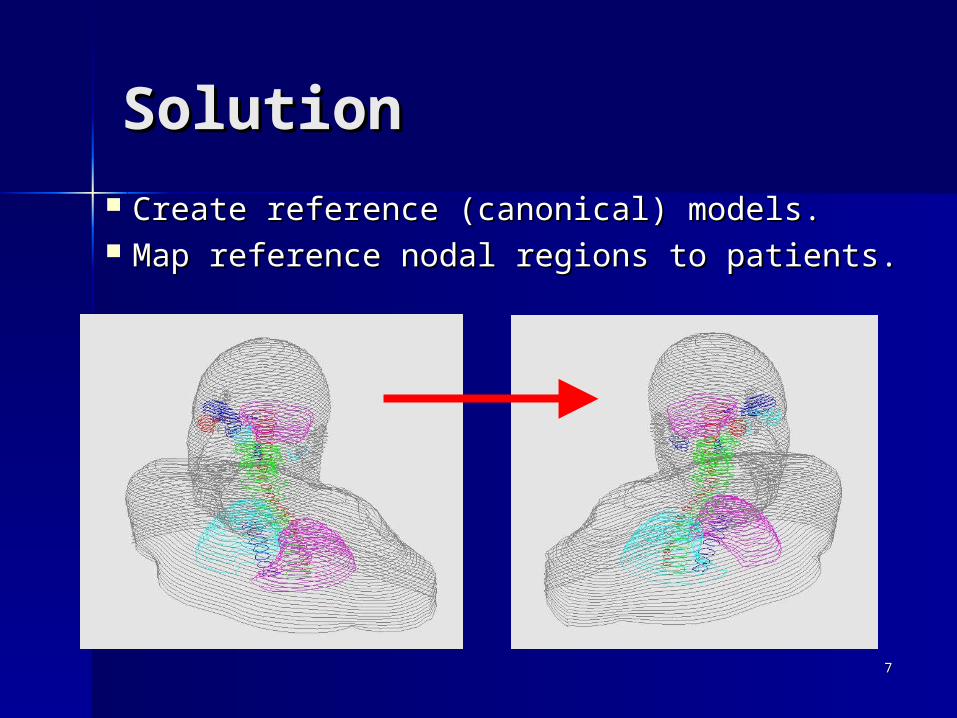
SolutionSolution
Create reference (canonical) models.Create reference (canonical) models. Map reference nodal regions to patients.Map reference nodal regions to patients.

88
System OverviewSystem Overview
Segmentation of Landmark Structures
Target CT Images
Projected Lymph Node Regions
Retrieve Similar Reference Models
3D Volume and Mesh of Mandible, Hyoid, ...
Image Registration
Reference Models with Lymph Node Regions

99
Image RegistrationImage Registration
Align the transformed reference image Align the transformed reference image ffRR ° ° gg to the target image to the target image ffT T . .
Find the optimal set of transformation Find the optimal set of transformation parameters parameters that maximize an image that maximize an image similarity function similarity function SS::
optimaloptimal = argmax = argmax SS(())

1010
Mattes’ MethodMattes’ Method
Similarity FunctionSimilarity Function
SS(()) = mutual_information( ffRR ° ° gg , f, fT T ))
Transformation FuncitonTransformation Funciton
gg((xx||) = ) = RR((x x - - xxCC) – ) – TT((x x - - xxCC) + ) + DD((xx||))
x x = [= [x, y, zx, y, z]]T T in the reference image in the reference image coordinates.coordinates.

1111
DeformableDeformable TransformationTransformation
Control points Control points (15*15*11).(15*15*11).
Each control point is Each control point is associated with a 3-associated with a 3-element deformation element deformation vector vector , describing , describing x-, y-, z-components x-, y-, z-components of the deformation.of the deformation.

1212
Project Target Lymph Project Target Lymph RegionsRegions
Image registration aligns Image registration aligns reference and target CT sets.reference and target CT sets.
Apply result transformation Apply result transformation gg to to reference lymph node regions.reference lymph node regions.
Incorporate anatomical landmark Incorporate anatomical landmark correspondences.correspondences.
Use surface mesh of outer body Use surface mesh of outer body contour, mandible, hyoid …contour, mandible, hyoid …
1313
Surface WarpingSurface Warping
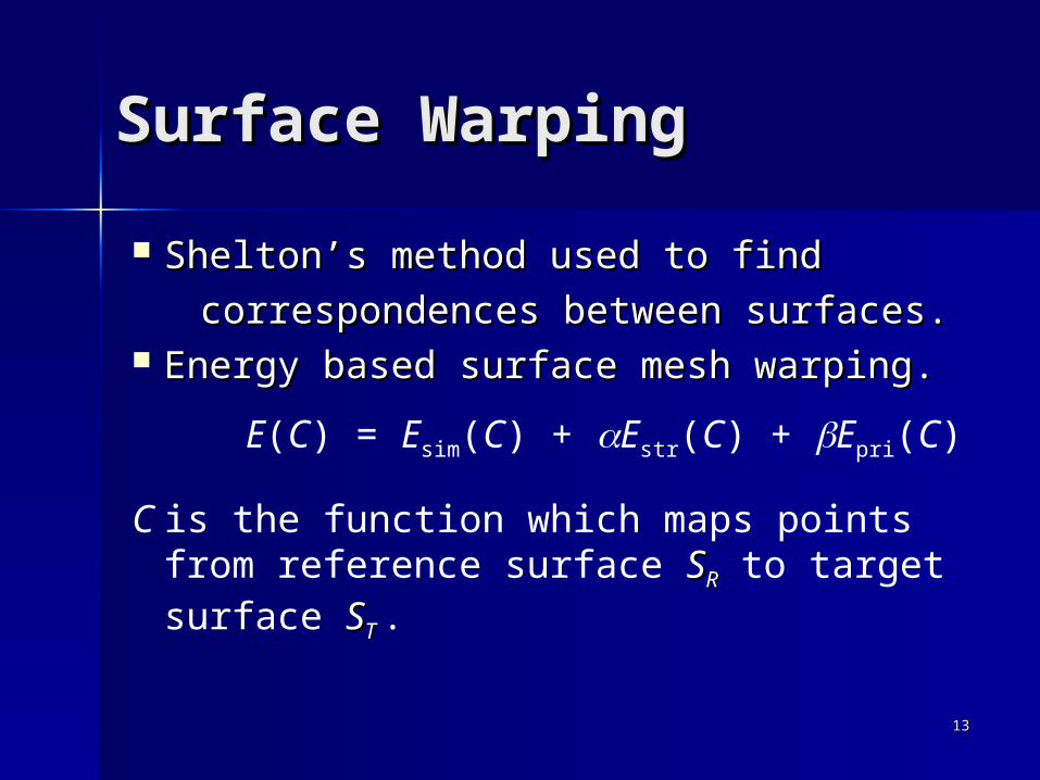
Shelton’s method used to find Shelton’s method used to find
correspondences between surfaces.correspondences between surfaces. Energy based surface mesh warping.Energy based surface mesh warping.
E(C) = Esim(C) + Estr(C) + Epri(C)
C is the function which maps points from reference surface SSRR to target surface SST T .
1414
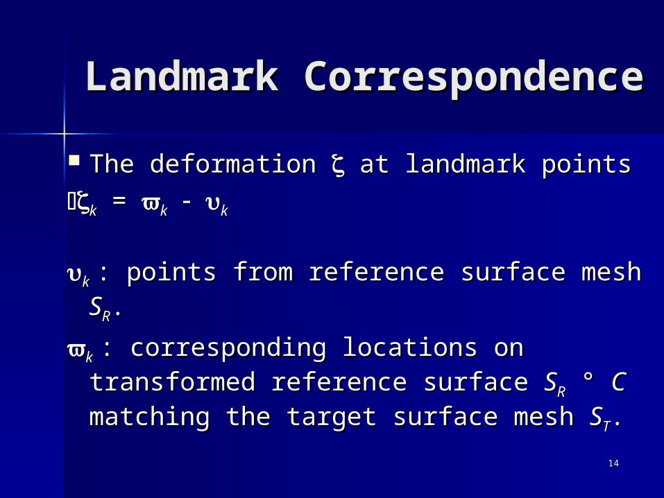
Landmark Landmark CorrespondenceCorrespondence
The deformation The deformation at landmark points at landmark points
kk = = kk kk
kk : points from reference surface mesh : points from reference surface mesh SSRR..
kk : corresponding locations on : corresponding locations on transformed reference surface transformed reference surface SSRR ° ° CC matching the target surface mesh matching the target surface mesh SSTT..

1515
Surface SSRR Surface SSTT
SSRR ° ° CC kk = = kk kk

1616
Using Landmark Using Landmark CorrespondenceCorrespondence Deformation vectorsDeformation vectors DD((jj) ) are are
modified according to landmark modified according to landmark correspondencescorrespondences kk in the in the proximity of the control pointsproximity of the control points jj..
Landmark structures align better.Landmark structures align better. Faster convergence.Faster convergence.

1717
Reference Mattes w/ Landmark Target
Compare Image Compare Image Registration ResultsRegistration Results

1818
Reference Mattes w/ Landmark Target
1919
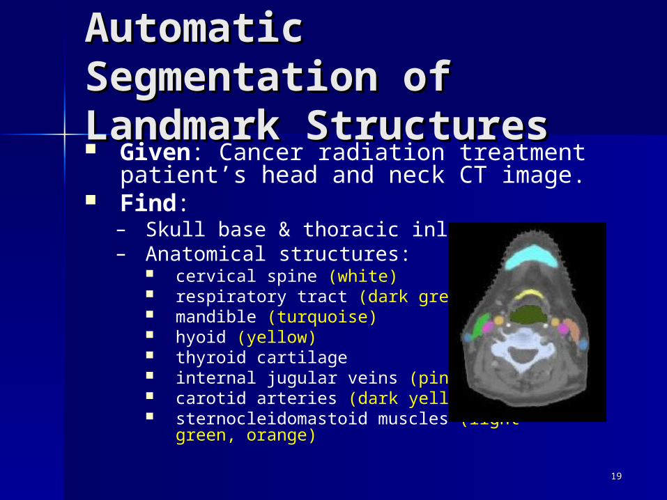
Automatic Automatic Segmentation of Segmentation of Landmark StructuresLandmark Structures Given: Cancer radiation treatment
patient’s head and neck CT image. Find:
– Skull base & thoracic inlet.– Anatomical structures:
cervical spine (white) respiratory tract (dark green) mandible (turquoise) hyoid (yellow) thyroid cartilage internal jugular veins (pink) carotid arteries (dark yellow) sternocleidomastoid muscles (light green,
orange)
2020
MethodMethod
2D knowledge-based segmentation– Based on Kobashi’s work– Dynamic thresholding– Progressive landmarking
Combined with 3D active contouring– Do not require successful 2D Do not require successful 2D
segmentation on every axial slicesegmentation on every axial slice– Initialize with 2D segmentation result

2121
A B C D
E
2D Segmentation 2D Segmentation ResultsResults

2222
2D/3D Iteration2D/3D Iteration
1 3 5
2 4 6
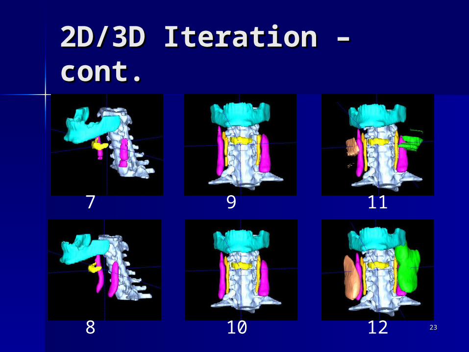
Identify objects that are easy to find, use them to find harder ones.
2323
2D/3D Iteration – cont.2D/3D Iteration – cont.
7 9 11
8 10 12

2424
Geometrical Feature- Geometrical Feature- Based SimilarityBased Similarity Given: A stored database DB of CT
scans from prototypical reference head and neck cancer patients and a single query CT scan Q from a target patient.
Find: Similarity between Q and each database image d in DB in order to find the most similar database images {ds}.

2525
StructuresStructures
Outer body Outer body contourcontour
MandibleMandible HyoidHyoid Internal Internal
jugular jugular veinsveins

2626
Feature TypesFeature Types
Simple Simple numeric 3D regional numeric 3D regional properties: volume and extents. properties: volume and extents.
VectorVector properties: relative properties: relative location between structures.location between structures.
ShapeShape properties: surface meshes properties: surface meshes of structures.of structures.
2727
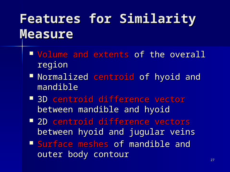
Features for Similarity Features for Similarity MeasureMeasure
Volume and extents Volume and extents of the overall of the overall regionregion
Normalized Normalized centroidcentroid of hyoid and of hyoid and mandiblemandible
3D 3D centroid difference vector centroid difference vector between between mandible and hyoidmandible and hyoid
2D 2D centroid difference vectorscentroid difference vectors between between hyoid and jugular veinshyoid and jugular veins
Surface meshes Surface meshes of mandible and outer of mandible and outer body contourbody contour

2828
Mesh Feature Distance Mesh Feature Distance
Register reference mesh Register reference mesh SR and and target mesh target mesh ST with Iterative with Iterative Closest Point (ICP), result Closest Point (ICP), result T..
Hausdorff distance Hausdorff distance between between two aligned surface meshes, TSR and ST
),(max),( TSp
TRh STpdSTSdR
The Hausdorff distance is the maximum distance from anypoint in the transformed reference image to the test image.

2929
Feature Vector Feature Vector DistanceDistance Given feature vectors Given feature vectors FFdd and and FFQQ
for model for model dd and query and query QQ in the in the feature vector space feature vector space RRNN..
2
1
2
1
),(),(
iQ
N
iidiiQdF FFdwFFD

3030
EvaluationEvaluation Surface mesh distance after full Surface mesh distance after full
image registration image registration DDHH – slow. – slow. Feature vector distance Feature vector distance DDFF – fast. – fast.
DH
DF
corr_coef(corr_coef(DDHH, , DDFF) )
= 0.72= 0.72
Images with smallfeature vector distanceshould produce the bestresults after registration.
3131
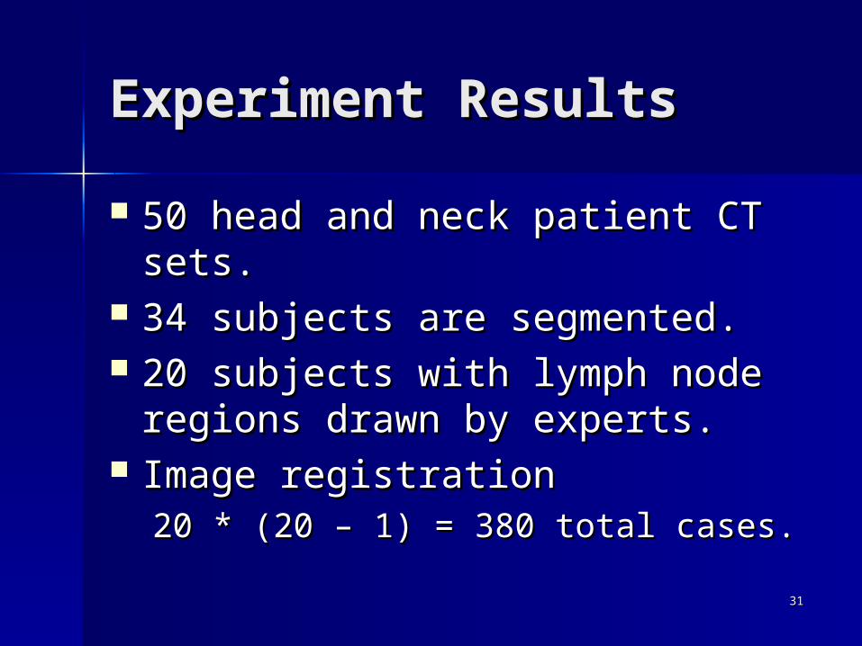
Experiment ResultsExperiment Results
50 head and neck patient CT sets.50 head and neck patient CT sets. 34 subjects are segmented.34 subjects are segmented. 20 subjects with lymph node 20 subjects with lymph node
regions drawn by experts.regions drawn by experts. Image registrationImage registration
20 * (20 – 1) = 380 total cases.20 * (20 – 1) = 380 total cases.
3232
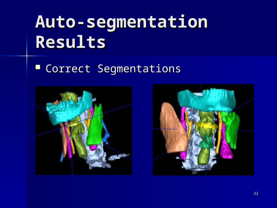
Auto-segmentation Auto-segmentation ResultsResults Correct SegmentationsCorrect Segmentations
3333
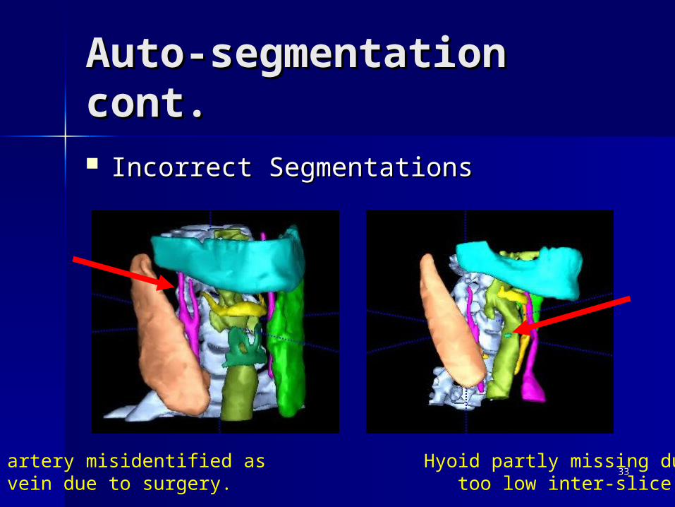
Auto-segmentation Auto-segmentation cont.cont. Incorrect SegmentationsIncorrect Segmentations
Carotid artery misidentified as Hyoid partly missing due tojugular vein due to surgery. too low inter-slice resolution.

3434
Successs Failure Incorrect % of success
Cervical Spine 34 0 0 100.00%
Respiratory Tract 34 0 0 100.00%
Mandible 34 0 0 100.00%
Hyoid 34 0 0 100.00%
ThyroidCartilage 33 0 1 97.06%
Left Internal Jugular Vein 27 3 4 79.41%
Right Internal Jugular Vein 31 1 2 91.18%
Left Carotid Artery 25 9 0 73.53%
Right Carotid Artery 30 4 0 88.24%
Left SCM 24 10 0 70.59%
Right SCM 25 9 0 73.53%
Auto-segmentation Auto-segmentation cont.cont.

3535
Image Registration Image Registration ResultsResults
Total cases Successful Success rate (%)
Mattes method 380 367 96.57%
New method using landmark correspondence 380 380 100.00%
Average Standard deviation
Mattes method 32 minutes 6 minutes
New method using landmark correspondence 26 minutes 5 minutes
Time of Convergence
Success/Failure

3636
Quantitative Quantitative Evaluation -Evaluation - Surface Surface Mesh DistanceMesh Distance
Projected Region SR ° ° ggColor is Color is distance to distance to truth.truth.
Ground Truth: Expert Drawn Target Region ST
DH(SR ° ° gg, ST, n) : Hausdorff distancen : lymph node region

3737
Average Standard deviation
Mattes method 2.85 1.44
New method using landmark correspondence 2.12 0.64
DH(SR ° ° gg, ST, 1B) for all SR, ST.
Measurement in centimeter.
Mattes distance larger thanlandmark distance.

3838
Average Standard deviation
Mattes method 1.02 0.51
New method using landmark correspondence 0.59 0.21
Mean_distance(SR ° ° gg, ST, 1B) for all SR, ST.
Measurement in centimeter.

3939
Similarity EvaluationSimilarity Evaluation
RH(i, Q) : the ith ranked reference subject for target Q based on the image registration results, DH.
RF(i, Q) : the ith ranked reference subject based on geometrical features, DF.
P(P(RRFF(1(1, Q, Q)) ==RRHH((11, Q, Q)) = 80%)) = 80%
P(P(RRFF(1(1, Q, Q)) ==RRHH((22, Q, Q)) = 10%)) = 10%
P(P(RRFF(1(1, Q, Q)) ==RRHH((33, Q, Q)) = 4%)) = 4%
Q
di
HausdorffDistance
FeatureDistance
RH(1, Q)
RH(2, Q)
RF(1, Q)
RF(2, Q)
4040
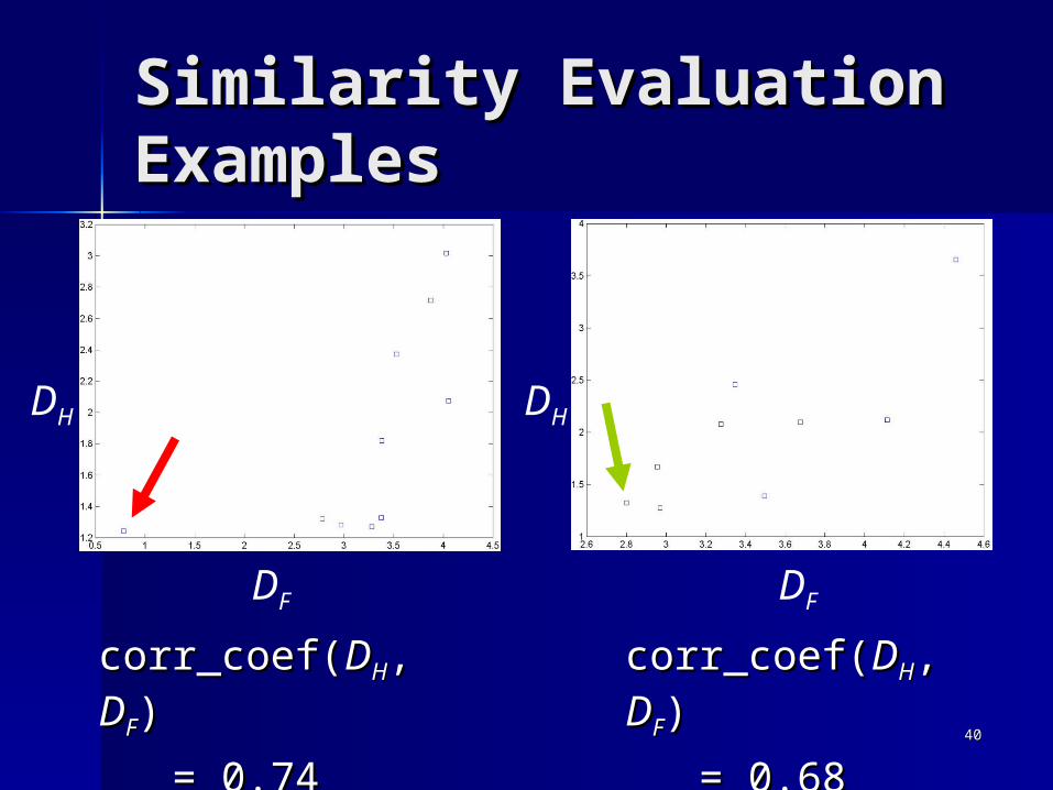
Similarity Evaluation Similarity Evaluation ExamplesExamples
DH DH
DF DF
corr_coef(corr_coef(DDHH, , DDFF) )
= 0.74= 0.74
corr_coef(corr_coef(DDHH, , DDFF) )
= 0.68= 0.68
4141
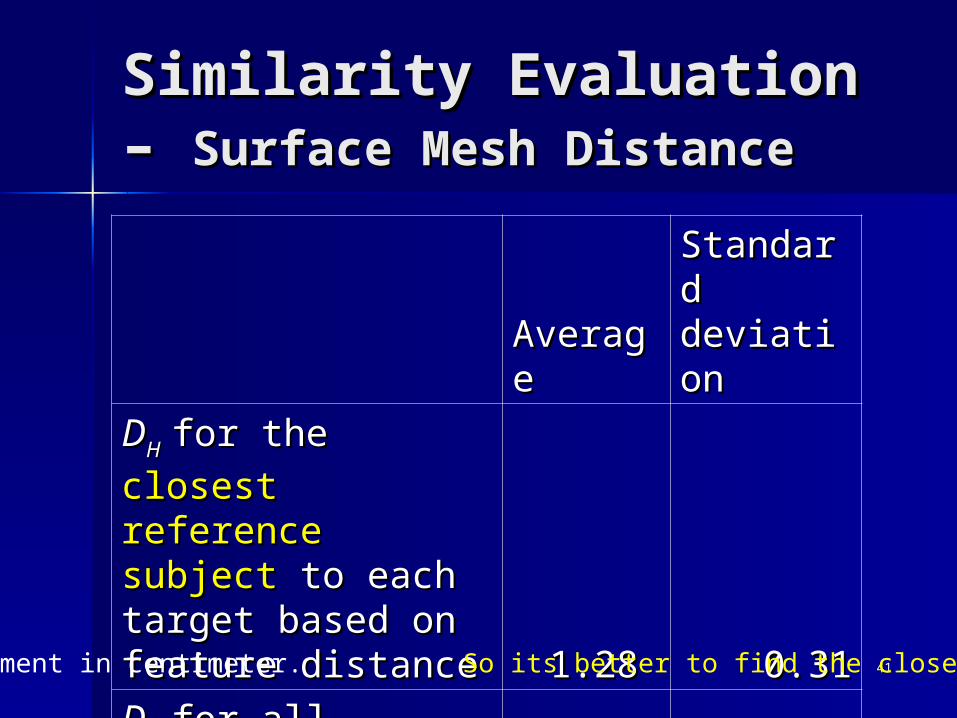
Similarity Evaluation – Similarity Evaluation – Surface Mesh DistanceSurface Mesh Distance
AveragAveragee
Standard Standard deviatiodeviationn
DDH H for the for the closest closest
reference subject reference subject to each target to each target based on feature based on feature distancedistance 1.28 1.28 0.310.31
DDH H for all reference for all reference
and target subjectsand target subjects 2.592.59 0.900.90Measurement in centimeter. So its better to find the closest subject.
4242
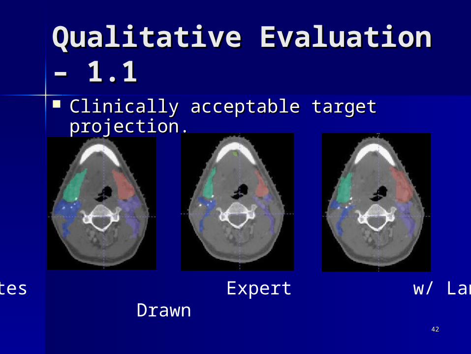
Qualitative Evaluation – Qualitative Evaluation – 1.11.1
Mattes Expert w/ Landmark Drawn
Clinically acceptable target projection.Clinically acceptable target projection.

4343
Mattes Expert w/ Landmark Drawn
Qualitative Evaluation – Qualitative Evaluation – 1.21.2 Clinically acceptable target projection.Clinically acceptable target projection.

4444
Mattes Expert w/ Landmark Drawn
Qualitative Evaluation – Qualitative Evaluation – 1.31.3 Clinically acceptable target projection.Clinically acceptable target projection.

4545
Mattes Expert w/ Landmark Drawn
Qualitative Evaluation – Qualitative Evaluation – 22 Clinically Clinically unacceptableunacceptable target target
projection.projection.

4646
ConclusionConclusion
Inter-subject image registration Inter-subject image registration technique shows promise for lymph technique shows promise for lymph node region auto-contouring.node region auto-contouring.
Knowledge-based auto-segmentation Knowledge-based auto-segmentation is useful for head and neck CT.is useful for head and neck CT.
Fast similar subject search is Fast similar subject search is possible and critical as reference possible and critical as reference database grows.database grows.
4747
Future WorkFuture Work
Integrate and evaluated in a clinical Integrate and evaluated in a clinical environment.environment.
Generalize to other types of cancer.Generalize to other types of cancer. Regional lymphatic involvement prediction.Regional lymphatic involvement prediction. Improve image registration results.Improve image registration results. Improve auto-segmentation results.Improve auto-segmentation results.
– Validation logicValidation logic– Knowledge-based 3D active contour constraintsKnowledge-based 3D active contour constraints

4848
AcknowledgementAcknowledgement
Linda ShapiroLinda Shapiro Ira KaletIra Kalet Jim BrinkleyJim Brinkley David HaynorDavid Haynor David MattesDavid Mattes Mark WhippleMark Whipple Jerry BarkerJerry Barker Carolyn RutterCarolyn Rutter Rizwan Rizwan NuraniNurani
4949
ContributionsContributions
The first auto target contouring tool for The first auto target contouring tool for radiation therapy. radiation therapy. (AMIA 2002)(AMIA 2002)
An auto-segmentation method combining 2D An auto-segmentation method combining 2D dynamic thresholding and 3D active dynamic thresholding and 3D active contouring. contouring. (IEEE CBMS 2006)(IEEE CBMS 2006)
An image registration method using landmark An image registration method using landmark correspondences in conjunction with mutual correspondences in conjunction with mutual information optimization. information optimization. (IEEE ISBI 2006)(IEEE ISBI 2006)
A patient similarity measurement using 3D A patient similarity measurement using 3D geometrical features of anatomical structures. geometrical features of anatomical structures. (IEEE ISBI 2007)(IEEE ISBI 2007)


![Head and Neck target delineation using a novel PET ...orca.cf.ac.uk/96682/1/Berthon_ATLAASfinal_reviewed_ORCA[1].pdf · 6 Manual PET-based GTV delineation, currently used in most](https://static.fdocuments.in/doc/165x107/5c0e01fc09d3f282728c461c/head-and-neck-target-delineation-using-a-novel-pet-orcacfacuk966821berthonatlaasfinalreviewedorca1pdf.jpg)