he world's finest inverter. -...
40
Transcript of he world's finest inverter. -...

2
he world's finest inverter.The best control capability. The most requested functions.
FRENIC5000VG7S is our highest performing inverter developed using Fuji's leading technologies for the 21st century.The inverter has a multi-drive function for high performance control of motors, worldwide. System integration with UPAC (the optional card incorporating user-programmable functions) enhances the capabilities of machines and devices such as vertical transfer equipment (cranes, elevator, multi-storied parking facilities), winding machines, injection molding machines, textile machines and production lines (like those used in the steel industry). These enhancements allow for comprehensive cost reductions. The wide range of capacity, conformity to world standards, and multi-language KEYPAD panel make the inverter ready for applications all over the world.
T

3
A standard product that conforms to UL/cUL and CE marking, allowing unification of devices and machines made at home and abroad.The KEYPAD panel is set for 8 languages as
standard to make exporting simple.Various options to connect to all types of the
field bus are available.
A single specification with a capacity range from 0.75kW to 400kW makes system construction simple.Optimal control is achieved with the CT use (constant
torque) for 150% overload capability, the VT use (variable torque) for 110% overload capability and the HT use for 200%/170% overload torque.
UPAC, the optional card incorporating user-programmable functions, enables user-original system configuration and construction. Dedicated package software products are also available.The RS485 communication function is provided as
standard and T-Link and SX bus communication functions are available as options.Inverter support loader for Windows is supplied
to facilitate function code setting.
The industry's best control
capability
Systemintegration
A wealth of integrated functions
Global products
A wide range of capacities
and applications
The multi-drive functions have vector control, sensorless vector control, V/f control and vector control for synchronous motors.Vector control with dedicated motors has attained
the industry's best control capabilities such as; speed control accuracy of ±0.005%, speed response of 100Hz, current response of 800Hz and torque control accuracy (linearity) of ±3%.
The industry's best control capability System integration
The tuning function has been enhanced to optimally control different motors. Load vibration suppressing observer and load
adaptive control functions are built in. Position control functions, such as zero speed
locking control, have been upgraded. Position synchronization control using pulse train
input is available as an option. Orientation control is available as an option.
A wealth of integrated functions Global products
A wide range of capacities and applications

4
This high performance vector control inverter has complete control over speed and tprque
Speed response characteristics
1-25.0
25.0
10 100 1000Frequency [Hz]
FRN37VG7S-4VG7 : 105Hz, -3dB
: 54Hz, -3dBVG5
Mg[dB]
1-360.0
0.0
10 100 1000Frequency [Hz]
Phase[deg]
Follow-up characteristics under impact load
0.2s
Load on(100%)
Torque current reference value
Actual speed
Motor current
Load off(0%)
100%
100 r/min
FRN7.5VG7S-2, at 500r/min
Speed-torque characteristics
150
100
50
0
-50
-100
-150
[30kW]
Axi
al to
rque
[%]
1000 2000 3000 3600
Wow characteristics
Conventional model (FRENIC5000VG5)
FRENIC5000VG7S
2.5r/min
1.5r/min
[37kW]
Wow at low speed has been improved down to 60% or less (1Hz) by enhancing the speed response frequency by 2 times (compared with VG5), digital speed control accuracy by one tenth, and current control response by four times (compared with VG5).
The industry's best control capability
Use with different control types (multi-drive function)
Speed control accuracy of ±0.005% (tested with a dedicated motor with PG under vector control: one half compared to our conventional model).
Speed response of 100Hz (tested with a dedicated motor with PG under vector control: two times compared to our conventional model).
Current response of 800Hz (tested with a dedicated motor with PG under vector control: four times compared to our conventional model).
Torque control accuracy (linearity) of ±3%.
You can select from four types of control for different motors; vector control, sensorless vector control, V/f control for induction motors, and vector control for synchronous motors (optional card required).
(*) : One class smaller model applicable.
A wide range of capacity/flexible applications
Simple system construction based on a single specification with a capacity range from 0.75kW to 400kW.
A standard product that meets three specifications.
Specification type Overload Main application Carrier frequency
CT 150% Constant torque applications High frequency
VT(*) 110% Variable torque applications Low frequency
HT 200% / 170% Vertical transfer applications High frequency
Motor speed [r/min]
LEVELUP

5
Built-in user-programmable functions (option as UPAC)
Users can personalize inverter control and terminal functions in order to build an original system using the programmable functions of UPAC (User Programmable Application Card) .
Dedicated package software products for tension control, dancer control and position control are provided.
Enhanced network readiness
The RS485 communication function is provided as standard, and the T-Link and SX bus functions areprovided as options.
Different field bus types (Profibus-DP, DeviceNet, etc) can also be used.
Inverter support loader provided
An inverter support loader for Windows is available as an option to facilitate function code setting.
Link for inverters (optical or simplified 485 communication), min. 2ms cycle with optical transmission
Personal computer
RS485(38.4kbps)
Inverter support loaderUPAC support loader(Equivalent to D300win)RS485/RS232C converter(Recommended: NP4H-CNV)
UPAC is installed only on a master VG7 inverterAn inverter link option is installed on each inverter
FRENIC5000VG7S dedicated motors or general-purpose motors
UPAC System
T-Link SystemMICREX-F or MICREX-SX with T-Link module Personal computer
RS485(38.4kbps)
T-Link(500kbps)
RS485/RS232C converter(Recommended: NP4H-CNV)
VG7 with T-Link option
FRENIC5000VG7S dedicated motorsor general-purpose motors
Install a dedicated SX bus option to connect with the SX bus. Install dedicated bus options to connect with different types of field buses (Profibus-DP, etc).
You can set an operational environment easily with the inverter support loader software by connecting to your personal computer over built-in RS485 interface (max. 38,400bps).
The loader runs on Windows95/98 and NT. Real-time trace and historical trace are incorporated along with an operation monitor and function settings.
UPAC

6
Enhanced built-in functions
Improved tuning functionMotor parameters can be tuned while the motor is stopped.
Built-in observer function for load vibration suppressing
Equipped with load adaptive control functionStepless variable double-speed control is possible at low speed.
Increased position controlZero-speed locking control is possible.Position synchronizing control with pulse train input ispossible as an option.Orientation control is possible as an option.
Vector control is applicable to two types of motors. Also, V/f control is applicable to the thirdmotor.
Conformity to world standards
Standard conformity to EC Directive (CE marking), UL and cUL standards enables unification of specifications at home and abroad
Conforms to the European EMC Directive with optional EMC filters
Upgraded maintenance/protective functions
I/O terminal checking function Main circuit capacitor life judgment Inverter load factor measure Records and displays accumulated operation time Displays operating conditions such as output
voltage, heat sink temperature and calculated torque value
Detailed data is recorded on the inverter trip Setting the thermal time constant of
the electronic thermal overload relay makesdiffernt motors applicable.
Standard protective function against input phase loss. Protects the inverter from damage caused by power line disconnection
Motor protection with PTC thermistor Equipped with terminals for connecting DC
REACTOR that can suppress harmonics
Interactive KEYPAD panel for simple operation
Standard copy functionEasily copies function code data to other inverters.
Remote operation capabilityThe KEYPAD panel is detachable for remote operation using an optional cable.
8 standard language operation (English, German, French, Italian, Spanish, Chinese, Korean and Japanese)
Jogging operation from the KEYPAD panel orwith input from an external signal
Switching between KEYPAD operations (LOCAL) and external signal input operations (REMOTE) using the KEYPAD panel
Built-in braking unitBuilt-in braking unit for 55kW or smaller models (200V series) and for 110kW or smaller models (400V series) allows for downsizing machines and devices.
23 I/O terminal points
Built-in PG feedback cardBoth 12V and 15V voltage inputs are accepted. The card can handle line drivers as an option.
Analog
Digital
Input
3 points
11 points
Output
3 points
6 points
North America/CanadaUL and cUL standards
EuropeEC Directive (CE marking)
Note: Among FRENIC5000VG7S series, only 400V series conform to the EN standards.
7
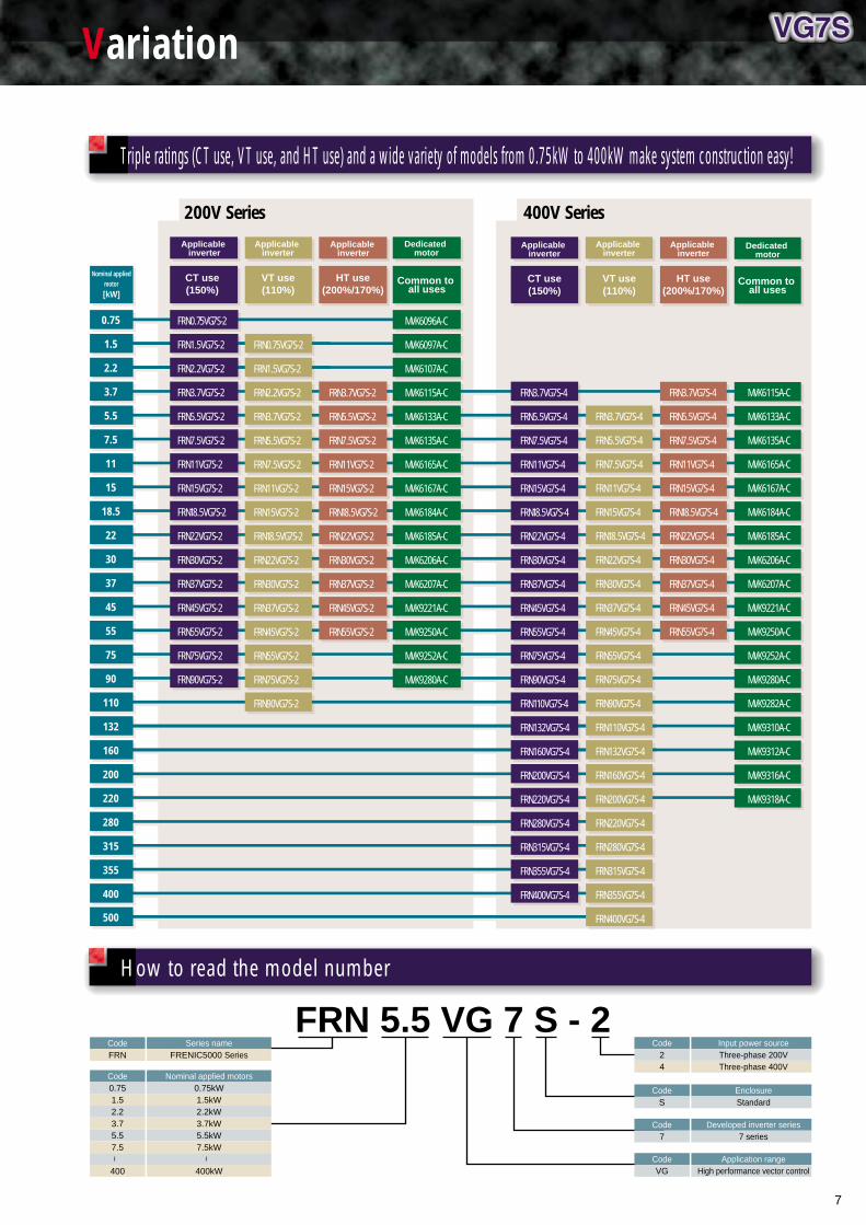
Triple ratings (CT use, VT use, and HT use) and a wide variety of models from 0.75kW to 400kW make system construction easy!
How to read the model number
FRN0.75VG7S-2
FRN1.5VG7S-2
FRN2.2VG7S-2
FRN3.7VG7S-2
FRN5.5VG7S-2
FRN7.5VG7S-2
FRN11VG7S-2
FRN15VG7S-2
FRN18.5VG7S-2
FRN22VG7S-2
FRN30VG7S-2
FRN37VG7S-2
FRN45VG7S-2
FRN55VG7S-2
FRN75VG7S-2
FRN90VG7S-2
FRN0.75VG7S-2
FRN1.5VG7S-2
FRN2.2VG7S-2
FRN3.7VG7S-2
FRN5.5VG7S-2
FRN7.5VG7S-2
FRN11VG7S-2
FRN15VG7S-2
FRN18.5VG7S-2
FRN22VG7S-2
FRN30VG7S-2
FRN37VG7S-2
FRN45VG7S-2
FRN55VG7S-2
FRN75VG7S-2
FRN90VG7S-2
FRN3.7VG7S-2
FRN5.5VG7S-2
FRN7.5VG7S-2
FRN11VG7S-2
FRN15VG7S-2
FRN18.5VG7S-2
FRN22VG7S-2
FRN30VG7S-2
FRN37VG7S-2
FRN45VG7S-2
FRN55VG7S-2
FRN3.7VG7S-4
FRN5.5VG7S-4
FRN7.5VG7S-4
FRN11VG7S-4
FRN15VG7S-4
FRN18.5VG7S-4
FRN22VG7S-4
FRN30VG7S-4
FRN37VG7S-4
FRN45VG7S-4
FRN55VG7S-4
FRN75VG7S-4
FRN90VG7S-4
FRN110VG7S-4
FRN132VG7S-4
FRN160VG7S-4
FRN200VG7S-4
FRN220VG7S-4
FRN280VG7S-4
FRN315VG7S-4
FRN355VG7S-4
FRN400VG7S-4
FRN3.7VG7S-4
FRN5.5VG7S-4
FRN7.5VG7S-4
FRN11VG7S-4
FRN15VG7S-4
FRN18.5VG7S-4
FRN22VG7S-4
FRN30VG7S-4
FRN37VG7S-4
FRN45VG7S-4
FRN55VG7S-4
400
500
355
315
280
220
200
160
132
110
90
75
55
45
37
30
22
18.5
15
11
7.5
5.5
3.7
2.2
1.5
0.75
Nominal applied motor
CT use(150%)
VT use(110%)
HT use(200%/170%)
HT use(200%/170%)
CT use(150%)
VT use(110%)
Applicable inverter
Applicable inverter
MVK6096A-C
MVK6097A-C
MVK6107A-C
MVK6115A-C
MVK6133A-C
MVK6135A-C
MVK6165A-C
MVK6167A-C
MVK6184A-C
MVK6185A-C
MVK6206A-C
MVK6207A-C
MVK9221A-C
MVK9250A-C
MVK9252A-C
MVK9280A-C
Common to all uses
Dedicated motor
Applicable inverter
Applicable inverter
Applicable inverter
MVK6115A-C
MVK6133A-C
MVK6135A-C
MVK6165A-C
MVK6167A-C
MVK6184A-C
MVK6185A-C
MVK6206A-C
MVK6207A-C
MVK9221A-C
MVK9250A-C
MVK9252A-C
MVK9280A-C
MVK9282A-C
MVK9310A-C
MVK9312A-C
MVK9316A-C
MVK9318A-C
Common to all uses
Dedicated motor
FRN 5.5 VG 7 S - 2CodeFRN
Series nameFRENIC5000 Series
CodeVG
Application rangeHigh performance vector control
Code7
Developed inverter series7 series
Code24
Input power sourceThree-phase 200VThree-phase 400V
CodeS
EnclosureStandard
Code0.751.52.23.75.57.5
400
Nominal applied motors0.75kW1.5kW2.2kW3.7kW5.5kW7.5kW
400kW
Applicable inverter
~ ~
FRN3.7VG7S-4
FRN5.5VG7S-4
FRN7.5VG7S-4
FRN11VG7S-4
FRN15VG7S-4
FRN18.5VG7S-4
FRN22VG7S-4
FRN30VG7S-4
FRN37VG7S-4
FRN45VG7S-4
FRN55VG7S-4
FRN75VG7S-4
FRN90VG7S-4
FRN110VG7S-4
FRN132VG7S-4
FRN160VG7S-4
FRN200VG7S-4
FRN220VG7S-4
FRN280VG7S-4
FRN315VG7S-4
FRN355VG7S-4
FRN400VG7S-4
200V Series 400V Series
[kW]
Variation

8
Digital settings reduce fluctuations on starting and stopping at zero-speed operations.
The torque detection signal drastically reduces rollbacks at starting.
1 15-step digital speed setting
Vector control inverters with sensors are applied to hoisting and elevating devices which require large starting torque and quick response while general-purpose motors and sensorless inverters are applied to traversing and traveling devices.
Torque bias
Load detection signal
M
FRENIC5000VG7S
ASR
Counterweight
Brake
Winding machine
: Auto Speed RegulatorVC : Vector ControlACR : Auto Current Regulator
Control block diagram
Soft starting and stopping with
S-curvesASR ACR
Digital speedsetting VC
Crane system configuration
Speed
Torque
Stopping
Stopping
Time
Starting
Torque bias
Operational characteristics
2 Multiple S-curves
Smooth acceleration and deceleration is achieved.
3 200% or more of maximum torque
Attains 200% of maximum torque using HT.
4 Torque bias function
5 Load adaptive control
Load adaptive control allows for stepless variable double-speed control at light load.
PWM converters drastically reduce harmonic current in power lines. Energy saving is achieved by supplying regenerative energy to power lines on winding-down or decelerating operations and utilizing the regenerative energy of individual inverter section (for example; applying regenerative energy from traverse to drive energy of elevating up/down) while providing a common DC power supply to inverters for traversing, elevating, and traveling devices.
Multiplexing windings of a hoist motor and providing an inverter with each winding can comply with the large capacity system.
Load adaptive control enables stepless variable double-speed control at light load.
Hoisting
Inverter(with sensor)
Inverter(with sensor)
Inverter(sensorless)
Inverter(sensorless)
Inverter(sensorless)
Inverter(with sensor)
Dedicated motor Dedicated motorMPG PG
General-purposemotor
General-purposemotor
General-purposemotorM
Elevating up/downTraversing
M M
Traveling
M
Dedicatedfilter
Dedicatedreactor
Dedicatedfilter
Dedicatedfilter
Dedicatedreactor
Dedicatedreactor
PWMconverter
PWMconverter
PWMconverter
VG7S VG7S VG7S VG7S VG7S VG7S
Multi-storied parking facilityFRENICS5000VG7 can build an optimal system for a multi-storied parking facility.
Crane1 Combination of vector control and sensorless vector control
2 PWM converter application
3 Multiple-winding motor drive function
4 Load adaptive control
PG
Application examples

9
Control block diagram
Control block diagram
Winding-off machine Winding-up machine
Master
Tension pickup
Tension pickup
Tension setting Line speed setting Tension setting
M PG M PG
MICREX-F or MICREX-SXThe PLC part can be configured with the UPAC.
VG7S VG7SMotor speed Motor speed
Torquelimiter
Speed reference
M PG
VG7S
Torquelimiter
Speed reference
Main speed reference
Fuji's PLC calculates winding diameter by reading the line speed and motor speed of the winding-up machine. The winding diameter of winding-off machines is calculated from the line speed and motor speed of the winding-off machine.
Different types of drawings are conducted on the same wire drawing line and die diameters vary according to wire. Employing Fuji's PLC and entering diameters as digital values after setting reduction ratios in the mechanical system and motor speed enables high-precision speed setting to skip readjusting when dies are changed.
The reference speed is provided such that the peripheral speed of a spool remains constant by reading in the line speed and the motor speed while the diameter of the spool continuously changes.
Dancer control prevents lines from breaking due to differences in tensions among drawing machines and keeps the tensions constant. Dancer roll positions are set such that tensions among drawing machines are balanced when dancer rolls are at sensor positions. The PLC detects the movement of dancer rolls from tension imbalances and corrects the speeds to return the dancer rolls to sensor positions. A PID controller for adjusting dancer roll positions is integrated into the PLC.
Torque is set, based on the following limitations because applying reference torque values corresponding to tension references directly into inverters may increase motor speed to the overspeed (OS) alarm level if there is breakage.
Speed reference ······· Speed reference higher than the speed of the motor is given to the winding-up device. Speed reference lower than the speed of the motor (or 0 [r/min]) is given to the winding-off device.
Torque limiter ······· Since inverters try to provide maximum torque with the speed references above, the PLC commands torque values corresponding to tension reference as torque limiter values.
Closed-loop control is also possible by employing tension pickups and inputting actual tensions into the PLC.
Torque reference is obtained from
Spool
Line speed settingDie diameter Die diameter
MICREX-F or MICREX-SXThe PLC part can be configured with the UPAC.
M PG
SG
VG7SMotor speed
Master
M PG
SG
VG7S
M PG
SG
VG7S
Dancer position Dancer position
Synchro Synchro Synchro
Amplifier for synchro
Amplifier for synchro
Amplifier for synchro
M PG
VG7S
Speed reference Speed reference Dancer positionSpeed reference Speed reference
Wire drawer Wire drawerDie Die Die
Using winding diameter calculation by PLC since tension reference cannot be input directly into the inverter.
Torque Tension Windingdiameter= ×
Winding-up and winding-off machinesThe following diagram shows simplified tension control for winding-up / off machines (torque reference open loop).
1 Winding diameter calculation
2 Torque control
Wire drawing line1 Die diameter calculation
2 Winding diameter calculation
3 Dancer control

10
Standard Specifications
Type FRN¤VG7S-2 0.75 1.5 2.2 3.7 5.5 7.5 11 15 18.5 22 30 37 45 55 75 90
Nominal applied motor [kW]
Rated capacity [kVA] (*1)
Rated current (Continuous)
(1min.)
Phase, Voltage, Frequency
Voltage/frequency variation
Momentary voltage dip
capability (*4)
Rated current [A] (with DCR)
(*7) (without DCR)
Required power supply capacity
[kVA] (*5)
Braking method /braking torque
Carrier frequency [kHz] (*6)
Mass [kg]
Enclosure
Three-phase 200V series
0.75
1.9
5
7.5
3-phase 200 to 230V, 50Hz/60Hz
Voltage: +10 to -15%, Frequency: +5 to -5%, Voltage unbalance: 2% or less (*3)
When voltage drops from the rated voltage, the inverter will continue operation if the voltage is more than 165V.
If the voltage is less than 165V, the inverter can be operated for 15ms.
3.1
6.4
1.1
Braking resistor discharge control: 150% braking torque, Separately installed braking resistor (option), Separately
installed braking unit (option for 75kW or more)
0.75 to 15
7
Up to 15kW: IP20, 18.5kW or over: IP00 (IP20: option)
1.5
3.0
8
12
5.7
11.1
2.0
7
2.2
4.1
11
16.5
8.3
16.1
2.9
7
3.7
6.8
18
27
14.0
25.5
4.9
8
5.5
10
27
40.5
19.7
40.8
6.9
8
7.5
14
37
55.5
26.9
52.6
9.4
8
11
18
49
73.5
39.0
76.9
14
12.5
15
24
63
94.5
54.0
98.5
19
12.5
18.5
28
74
111
3-phase 200 to 220V/50Hz, 200 to 230V/60Hz (*2)
66.2
117
23
25
22
34
90
135
78.8
136
28
25
30
44
116
174
109
168
38
30
37
55
145
217.5
135
204
47
37
45
68
180
270
163
243
57
46
55
81
215
333
199
291
69
48
75
107
283
441
272
—
95
0.75 to 10
70
90
131
346
519
327
—
114
115
Input
ratings
Three-phase 400V series
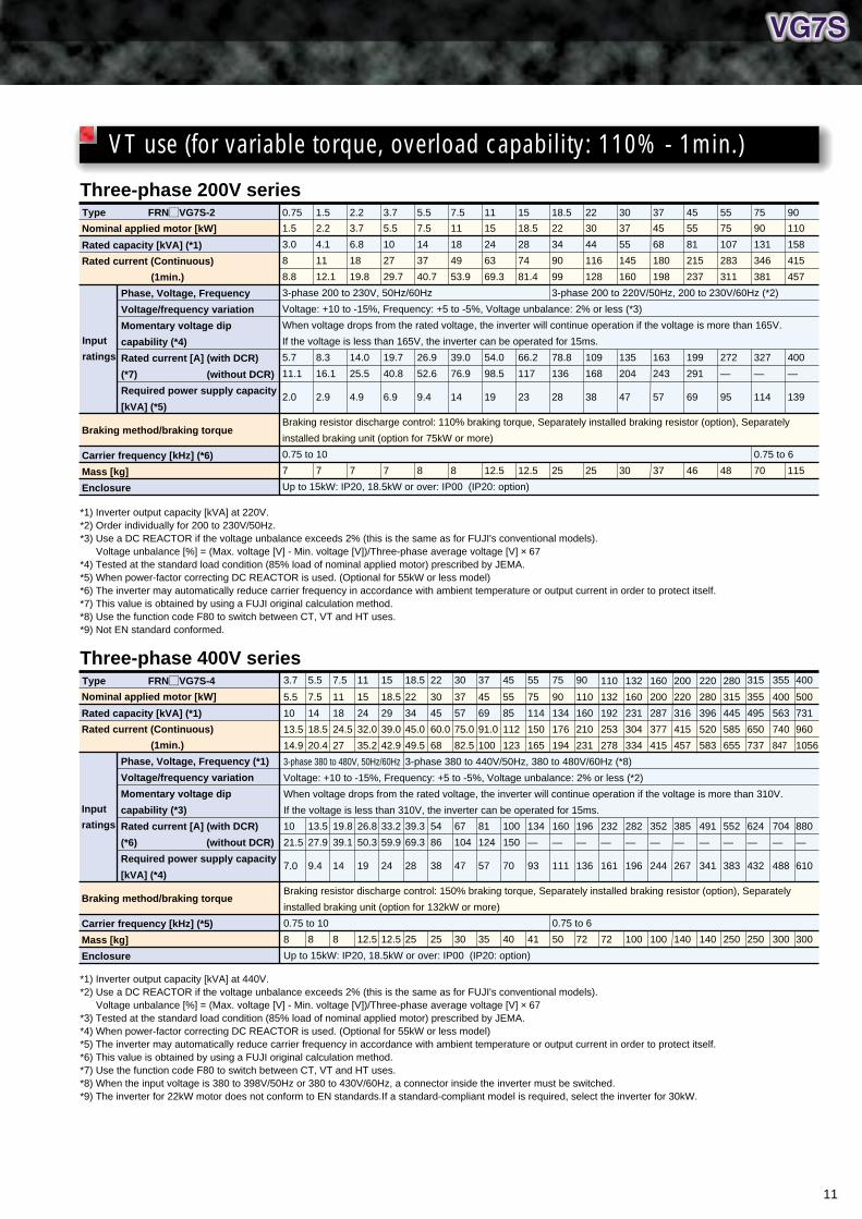
*1) Inverter output capacity [kVA] at 220V.*2) Order individually for 200 to 230V/50Hz.*3) Use a DC REACTOR if the voltage unbalance exceeds 2% (this is the same as for FUJI's conventional models).
Voltage unbalance [%] = (Max. voltage [V] - Min. voltage [V])/Three-phase average voltage [V] × 67*4) Tested at the standard load condition (85% load of nominal applied motor) prescribed by JEMA.*5) When power-factor correcting DC REACTOR is used. (Optional for 55kW or less model)*6) The inverter may automatically reduce carrier frequency in accordance with ambient temperature or output current in order to protect itself.*7) This value is obtained by using a FUJI original calculation method.*8) Use the function code F80 to switch between CT, VT and HT uses.*9) Not EN standard conformed.
*1) Inverter output capacity [kVA] at 440V.*2) Use a DC REACTOR if the voltage unbalance exceeds 2% (this is the same as for FUJI's conventional models).
Voltage unbalance [%] = (Max. voltage [V] - Min. voltage [V])/Three-phase average voltage [V] × 67*3) Tested at the standard load condition (85% load of nominal applied motor) prescribed by JEMA.*4) When power-factor correcting DC REACTOR is used. (Optional for 55kW or less model)*5) The inverter may automatically reduce carrier frequency in accordance with ambient temperature or output current in order to protect itself.*6) This value is obtained by using a FUJI original calculation method.*7) Use the function code F80 to switch between CT, VT and HT uses.*8) When the input voltage is 380 to 398V/50Hz or 380 to 430V/60Hz, a connector inside the inverter must be switched.*9) The inverter for 18.5kW motor does not conform to EN standards.If a standard-compliant model is required, select the inverter for 22kW.
Nominal applied motor [kW]
Rated capacity [kVA] (*1)
Rated current (Continuous)
(1min.)
Phase, Voltage, Frequency (*1)
Voltage/frequency variation
Momentary voltage dip
capability (*3)
Rated current [A] (with DCR)
(*6) (without DCR)
Required power supply capacity
[kVA] (*4)
Braking method/braking torque
Carrier frequency [kHz] (*5)
Mass [kg]
Enclosure
Type FRN¤VG7S-4
3.7
6.8
9.0
13.5
3-phase 380 to 480V, 50Hz/60Hz
Voltage: +10 to -15%, Frequency: +5 to -5%, Voltage unbalance: 2% or less (*2)
When voltage drops from the rated voltage, the inverter will continue operation if the voltage is more than 310V.
If the voltage is less than 310V, the inverter can be operated for 15ms.
7.1
14.9
5.0
Braking resistor discharge control: 150% braking torque, Separately installed braking resistor (option), Separately
installed braking unit (option for 132kW or more)
0.75 to 15
8
Up to 15kW: IP20, 18.5kW or over: IP00 (IP20: option)
3.7
5.5
10
13.5
20.0
10
21.5
7.0
8
5.5
7.5
14
18.5
27.5
13.5
27.9
9.4
8
7.5
11
18
24.5
36.5
19.8
39.1
14
12.5
11
15
24
32.0
48.0
26.8
50.3
19
12.5
15
18.5
29
39.0
58.5
3-phase 380 to 440V/50Hz, 380 to 480V/60Hz (*8)
33.2
59.9
24
25
18.5
22
34
45.0
67.5
39.3
69.3
28
25
22
30
45
60.0
90.0
54
86
38
30
30
37
57
75.0
113
67
104
47
35
37
45
69
91.0
137
81
124
57
40
45
55
85
112
168
100
150
70
41
55
75
114
150
225
134
—
93
0.75 to 10
50
75
90
134
176
264
160
—
111
72
90
110
160
210
315
196
—
136
72
110
132
192
253
360
232
—
161
100
132
160
231
304
456
282
—
196
100
160
200
287
377
566
352
—
244
140
200
220
316
415
623
385
—
267
140
220
280
396
520
780
491
—
341
250
280
315
445
585
878
552
—
383
250
315
355
495
650
975
624
—
432
300
355
400
563
740
1110
704
—
488
360
400
CT use (for constant torque, overload capability: 150% - 1min.)
Input
ratings
11
*1) Inverter output capacity [kVA] at 220V.*2) Order individually for 200 to 230V/50Hz.*3) Use a DC REACTOR if the voltage unbalance exceeds 2% (this is the same as for FUJI's conventional models).
Voltage unbalance [%] = (Max. voltage [V] - Min. voltage [V])/Three-phase average voltage [V] × 67*4) Tested at the standard load condition (85% load of nominal applied motor) prescribed by JEMA.*5) When power-factor correcting DC REACTOR is used. (Optional for 55kW or less model)*6) The inverter may automatically reduce carrier frequency in accordance with ambient temperature or output current in order to protect itself.*7) This value is obtained by using a FUJI original calculation method.*8) Use the function code F80 to switch between CT, VT and HT uses.*9) Not EN standard conformed.
0.75 1.5 2.2 3.7 5.5 7.5 11 15 18.5 22 30 37 45 55 75 90
Nominal applied motor [kW]
Rated capacity [kVA] (*1)
Rated current (Continuous)
(1min.)
Phase, Voltage, Frequency
Voltage/frequency variation
Momentary voltage dip
capability (*4)
Rated current [A] (with DCR)
(*7) (without DCR)
Required power supply capacity
[kVA] (*5)
Braking method/braking torque
Carrier frequency [kHz] (*6)
Mass [kg]
Enclosure
1.5
3.0
8
8.8
3-phase 200 to 230V, 50Hz/60Hz
Voltage: +10 to -15%, Frequency: +5 to -5%, Voltage unbalance: 2% or less (*3)
When voltage drops from the rated voltage, the inverter will continue operation if the voltage is more than 165V.
If the voltage is less than 165V, the inverter can be operated for 15ms.
5.7
11.1
2.0
Braking resistor discharge control: 110% braking torque, Separately installed braking resistor (option), Separately
installed braking unit (option for 75kW or more)
0.75 to 10
7
Up to 15kW: IP20, 18.5kW or over: IP00 (IP20: option)
2.2
4.1
11
12.1
8.3
16.1
2.9
7
3.7
6.8
18
19.8
14.0
25.5
4.9
7
5.5
10
27
29.7
19.7
40.8
6.9
7
7.5
14
37
40.7
26.9
52.6
9.4
8
11
18
49
53.9
39.0
76.9
14
8
15
24
63
69.3
54.0
98.5
19
12.5
18.5
28
74
81.4
66.2
117
23
12.5
22
34
90
99
3-phase 200 to 220V/50Hz, 200 to 230V/60Hz (*2)
78.8
136
28
25
30
44
116
128
109
168
38
25
37
55
145
160
135
204
47
30
45
68
180
198
163
243
57
37
55
81
215
237
199
291
69
46
75
107
283
311
272
—
95
48
90
131
346
381
327
—
114
0.75 to 6
70
110
158
415
457
400
—
139
115
*1) Inverter output capacity [kVA] at 440V.*2) Use a DC REACTOR if the voltage unbalance exceeds 2% (this is the same as for FUJI's conventional models).
Voltage unbalance [%] = (Max. voltage [V] - Min. voltage [V])/Three-phase average voltage [V] × 67*3) Tested at the standard load condition (85% load of nominal applied motor) prescribed by JEMA.*4) When power-factor correcting DC REACTOR is used. (Optional for 55kW or less model)*5) The inverter may automatically reduce carrier frequency in accordance with ambient temperature or output current in order to protect itself.*6) This value is obtained by using a FUJI original calculation method.*7) Use the function code F80 to switch between CT, VT and HT uses.*8) When the input voltage is 380 to 398V/50Hz or 380 to 430V/60Hz, a connector inside the inverter must be switched.*9) The inverter for 22kW motor does not conform to EN standards.If a standard-compliant model is required, select the inverter for 30kW.
Three-phase 200V series
Nominal applied motor [kW]
Rated capacity [kVA] (*1)
Rated current (Continuous)
(1min.)
Phase, Voltage, Frequency (*1)
Voltage/frequency variation
Momentary voltage dip
capability (*3)
Rated current [A] (with DCR)
(*6) (without DCR)
Required power supply capacity
[kVA] (*4)
Braking method/braking torque
Carrier frequency [kHz] (*5)
Mass [kg]
Enclosure
Three-phase 400V series
5.5
10
13.5
14.9
3-phase 380 to 480V, 50Hz/60Hz
Voltage: +10 to -15%, Frequency: +5 to -5%, Voltage unbalance: 2% or less (*2)
When voltage drops from the rated voltage, the inverter will continue operation if the voltage is more than 310V.
If the voltage is less than 310V, the inverter can be operated for 15ms.
10
21.5
7.0
Braking resistor discharge control: 150% braking torque, Separately installed braking resistor (option), Separately
installed braking unit (option for 132kW or more)
0.75 to 10
8
Up to 15kW: IP20, 18.5kW or over: IP00 (IP20: option)
3.7
7.5
14
18.5
20.4
13.5
27.9
9.4
8
5.5
11
18
24.5
27
19.8
39.1
14
8
7.5
15
24
32.0
35.2
26.8
50.3
19
12.5
11
18.5
29
39.0
42.9
33.2
59.9
24
12.5
15
22
34
45.0
49.5
3-phase 380 to 440V/50Hz, 380 to 480V/60Hz (*8)
39.3
69.3
28
25
18.5
30
45
60.0
68
54
86
38
25
22
37
57
75.0
82.5
67
104
47
30
30
45
69
91.0
100
81
124
57
35
37
55
85
112
123
100
150
70
40
45
75
114
150
165
134
—
93
41
55
90
134
176
194
160
—
111
0.75 to 6
50
75
110
160
210
231
196
—
136
72
90
132
192
253
278
232
—
161
72
110
160
231
304
334
282
—
196
100
132
200
287
377
415
352
—
244
100
160
220
316
415
457
385
—
267
140
200
280
396
520
583
491
—
341
140
220
315
445
585
655
552
—
383
250
280
355
495
650
737
624
—
432
250
315
400
563
740
847
704
—
488
300
355
500
731
960
1056
880
—
610
300
400
VT use (for variable torque, overload capability: 110% - 1min.)
Type FRN¤VG7S-2
Type FRN¤VG7S-4
Input
ratings
Input
ratings
12
Standard Specifications
Three-phase 200V series
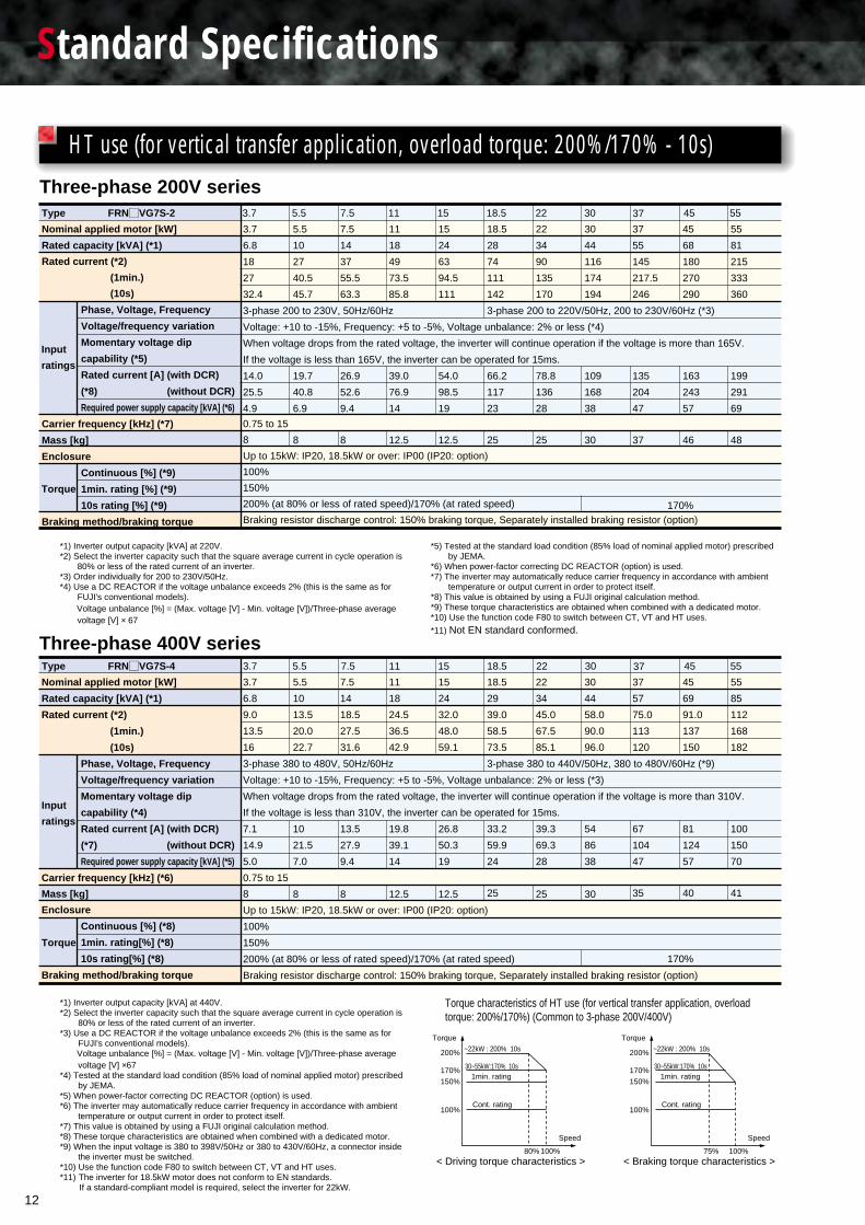
*1) Inverter output capacity [kVA] at 220V.*2) Select the inverter capacity such that the square average current in cycle operation is
80% or less of the rated current of an inverter.*3) Order individually for 200 to 230V/50Hz.*4) Use a DC REACTOR if the voltage unbalance exceeds 2% (this is the same as for
FUJI's conventional models). Voltage unbalance [%] = (Max. voltage [V] - Min. voltage [V])/Three-phase average
voltage [V] × 67
*5) Tested at the standard load condition (85% load of nominal applied motor) prescribed by JEMA.
*6) When power-factor correcting DC REACTOR (option) is used.*7) The inverter may automatically reduce carrier frequency in accordance with ambient
temperature or output current in order to protect itself.*8) This value is obtained by using a FUJI original calculation method.*9) These torque characteristics are obtained when combined with a dedicated motor.*10) Use the function code F80 to switch between CT, VT and HT uses.
*11) Not EN standard conformed.
Three-phase 400V series
*1) Inverter output capacity [kVA] at 440V.*2) Select the inverter capacity such that the square average current in cycle operation is
80% or less of the rated current of an inverter.*3) Use a DC REACTOR if the voltage unbalance exceeds 2% (this is the same as for
FUJI's conventional models). Voltage unbalance [%] = (Max. voltage [V] - Min. voltage [V])/Three-phase average
voltage [V] ×67*4) Tested at the standard load condition (85% load of nominal applied motor) prescribed
by JEMA.*5) When power-factor correcting DC REACTOR (option) is used.*6) The inverter may automatically reduce carrier frequency in accordance with ambient
temperature or output current in order to protect itself.*7) This value is obtained by using a FUJI original calculation method.*8) These torque characteristics are obtained when combined with a dedicated motor.*9) When the input voltage is 380 to 398V/50Hz or 380 to 430V/60Hz, a connector inside
the inverter must be switched.*10) Use the function code F80 to switch between CT, VT and HT uses.*11) The inverter for 18.5kW motor does not conform to EN standards. If a standard-compliant model is required, select the inverter for 22kW.
~22kW : 200% 10s
30~55kW:170% 10s1min. rating
Cont. rating
< Driving torque characteristics >
Torque
200%
170%
150%
100%
100%80%
Speed
~22kW : 200% 10s
30~55kW:170% 10s1min. rating
Cont. rating
Torque
200%
170%
150%
100%
100%75%
Speed
< Braking torque characteristics >
Torque characteristics of HT use (for vertical transfer application, overload torque: 200%/170%) (Common to 3-phase 200V/400V)
3.7 5.5 7.5 11 15 18.5 22 30 37 45 55
Nominal applied motor [kW]
Rated capacity [kVA] (*1)
Rated current (*2)
(1min.)
(10s)
Phase, Voltage, Frequency
Voltage/frequency variation
Momentary voltage dip
capability (*5)
Rated current [A] (with DCR)
(*8) (without DCR)
Required power supply capacity [kVA] (*6)
Carrier frequency [kHz] (*7)
Mass [kg]
Enclosure
Continuous [%] (*9)
1min. rating [%] (*9)
10s rating [%] (*9)
Braking method/braking torque
3.7
6.8
18
27
32.4
3-phase 200 to 230V, 50Hz/60Hz
Voltage: +10 to -15%, Frequency: +5 to -5%, Voltage unbalance: 2% or less (*4)
When voltage drops from the rated voltage, the inverter will continue operation if the voltage is more than 165V.
If the voltage is less than 165V, the inverter can be operated for 15ms.
14.0
25.5
4.9
0.75 to 15
8
Up to 15kW: IP20, 18.5kW or over: IP00 (IP20: option)
100%
150%
200% (at 80% or less of rated speed)/170% (at rated speed)
Braking resistor discharge control: 150% braking torque, Separately installed braking resistor (option)
5.5
10
27
40.5
45.7
19.7
40.8
6.9
8
7.5
14
37
55.5
63.3
26.9
52.6
9.4
8
11
18
49
73.5
85.8
39.0
76.9
14
12.5
15
24
63
94.5
111
54.0
98.5
19
12.5
18.5
28
74
111
142
3-phase 200 to 220V/50Hz, 200 to 230V/60Hz (*3)
66.2
117
23
25
22
34
90
135
170
78.8
136
28
25
30
44
116
174
194
109
168
38
30
37
55
145
217.5
246
135
204
47
37
45
68
180
270
290
163
243
57
46
55
81
215
333
360
199
291
69
48
Input
ratings
Torque
170%
3.7 5.5 7.5 11 15 18.5 22 30 37 45 55
Nominal applied motor [kW]
Rated capacity [kVA] (*1)
Rated current (*2)
(1min.)
(10s)
Phase, Voltage, Frequency
Voltage/frequency variation
Momentary voltage dip
capability (*4)
Rated current [A] (with DCR)
(*7) (without DCR)
Required power supply capacity [kVA] (*5)
Carrier frequency [kHz] (*6)
Mass [kg]
Enclosure
Continuous [%] (*8)
1min. rating[%] (*8)
10s rating[%] (*8)
Braking method/braking torque
5.5
10
13.5
20.0
22.7
10
21.5
7.0
8
7.5
14
18.5
27.5
31.6
13.5
27.9
9.4
8
11
18
24.5
36.5
42.9
19.8
39.1
14
12.5
15
24
32.0
48.0
59.1
26.8
50.3
19
12.5
18.5
29
39.0
58.5
73.5
3-phase 380 to 440V/50Hz, 380 to 480V/60Hz (*9)
33.2
59.9
24
25
22
34
45.0
67.5
85.1
39.3
69.3
28
25
30
44
58.0
90.0
96.0
54
86
38
30
37
57
75.0
113
120
67
104
47
35
45
69
91.0
137
150
81
124
57
40
55
85
112
168
182
100
150
70
41
Input
ratings
Torque
170%
3.7
6.8
9.0
13.5
16
3-phase 380 to 480V, 50Hz/60Hz
Voltage: +10 to -15%, Frequency: +5 to -5%, Voltage unbalance: 2% or less (*3)
When voltage drops from the rated voltage, the inverter will continue operation if the voltage is more than 310V.
If the voltage is less than 310V, the inverter can be operated for 15ms.
7.1
14.9
5.0
0.75 to 15
8
Up to 15kW: IP20, 18.5kW or over: IP00 (IP20: option)
100%
150%
200% (at 80% or less of rated speed)/170% (at rated speed)
Braking resistor discharge control: 150% braking torque, Separately installed braking resistor (option)
HT use (for vertical transfer application, overload torque: 200%/170% - 10s)
Type FRN¤VG7S-2
Type FRN¤VG7S-4
13
Common Specifications
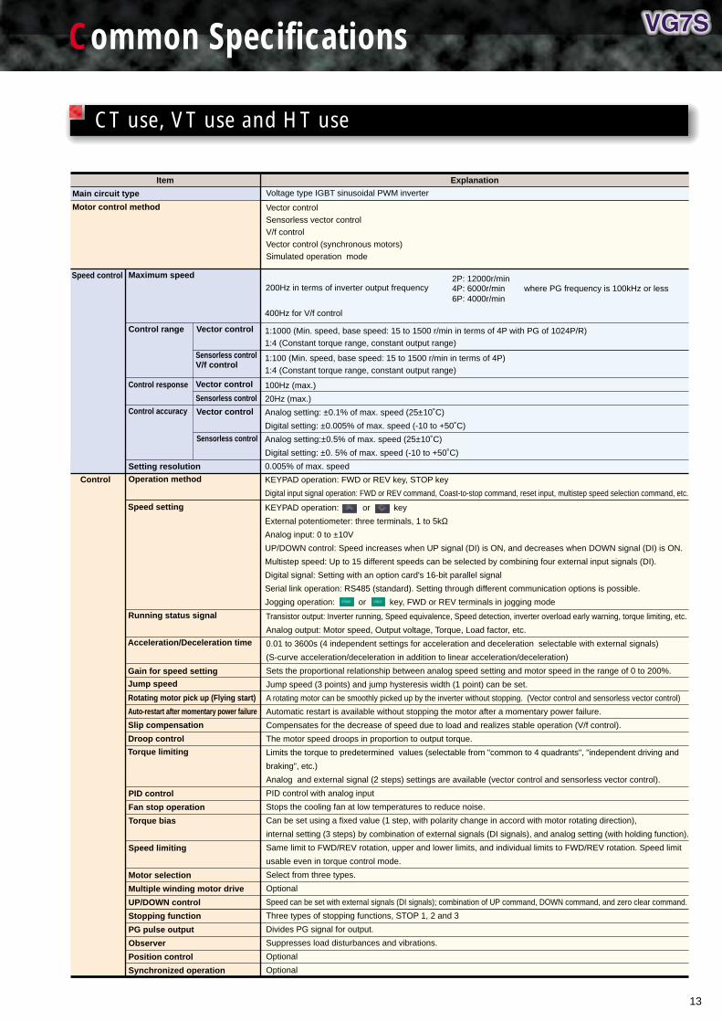
CT use, VT use and HT use
100Hz (max.)
20Hz (max.)
Analog setting: ±0.1% of max. speed (25±10˚C)
Digital setting: ±0.005% of max. speed (-10 to +50˚C)
Analog setting:±0.5% of max. speed (25±10˚C)
Digital setting: ±0. 5% of max. speed (-10 to +50˚C)
0.005% of max. speed
KEYPAD operation: FWD or REV key, STOP key
Digital input signal operation: FWD or REV command, Coast-to-stop command, reset input, multistep speed selection command, etc.
Main circuit type
Motor control method
Speed control
Sensorless control
Control response
4P: 6000r/min2P: 12000r/min
6P: 4000r/min where PG frequency is 100kHz or less200Hz in terms of inverter output frequency
Voltage type IGBT sinusoidal PWM inverter
Vector controlSensorless vector controlV/f controlVector control (synchronous motors)Simulated operation mode
Item Explanation
400Hz for V/f control
Transistor output: Inverter running, Speed equivalence, Speed detection, inverter overload early warning, torque limiting, etc.
Analog output: Motor speed, Output voltage, Torque, Load factor, etc.
0.01 to 3600s (4 independent settings for acceleration and deceleration selectable with external signals)
(S-curve acceleration/deceleration in addition to linear acceleration/deceleration)
Sets the proportional relationship between analog speed setting and motor speed in the range of 0 to 200%.
Jump speed (3 points) and jump hysteresis width (1 point) can be set.
A rotating motor can be smoothly picked up by the inverter without stopping. (Vector control and sensorless vector control)
Automatic restart is available without stopping the motor after a momentary power failure.
Compensates for the decrease of speed due to load and realizes stable operation (V/f control).
The motor speed droops in proportion to output torque.
Limits the torque to predetermined values (selectable from "common to 4 quadrants", "independent driving and
braking", etc.)
Analog and external signal (2 steps) settings are available (vector control and sensorless vector control).
PID control with analog input
Stops the cooling fan at low temperatures to reduce noise.
Can be set using a fixed value (1 step, with polarity change in accord with motor rotating direction),
internal setting (3 steps) by combination of external signals (DI signals), and analog setting (with holding function).
Same limit to FWD/REV rotation, upper and lower limits, and individual limits to FWD/REV rotation. Speed limit
usable even in torque control mode.
Select from three types.
Optional
Speed can be set with external signals (DI signals); combination of UP command, DOWN command, and zero clear command.
Three types of stopping functions, STOP 1, 2 and 3
Divides PG signal for output.
Suppresses load disturbances and vibrations.
Optional
Optional
Rotating motor pick up (Flying start)
Auto-restart after momentary power failure
Slip compensation
Droop control
Control
Acceleration/Deceleration time
Gain for speed setting
Jump speed
Running status signal
Torque limiting
PID control
Fan stop operation
Torque bias
Speed limiting
Motor selection
Multiple winding motor drive
UP/DOWN control
Stopping function
PG pulse output
Observer
Position control
Synchronized operation
Speed setting
Maximum speed
Control range
Control accuracy
Setting resolution
Operation method
Vector control
Sensorless controlV/f control
Vector control
Sensorless control
Vector control
1:100 (Min. speed, base speed: 15 to 1500 r/min in terms of 4P)1:4 (Constant torque range, constant output range)
1:1000 (Min. speed, base speed: 15 to 1500 r/min in terms of 4P with PG of 1024P/R)1:4 (Constant torque range, constant output range)
KEYPAD operation: or key
External potentiometer: three terminals, 1 to 5kΩAnalog input: 0 to ±10V
UP/DOWN control: Speed increases when UP signal (DI) is ON, and decreases when DOWN signal (DI) is ON.
Multistep speed: Up to 15 different speeds can be selected by combining four external input signals (DI).
Digital signal: Setting with an option card's 16-bit parallel signal
Serial link operation: RS485 (standard). Setting through different communication options is possible.
Jogging operation: or key, FWD or REV terminals in jogging mode

14
Common specifications
• DC fuse blown
• KEYPAD panel communication error
• Operation procedure error
• UPAC error
• Undervoltage
• External alarm input
• Motor 2 overload
• Overvoltage
• Ground fault
• Excessive position deviation
• CPU error
• Output wiring error
• Inter-inverter communication error
• NTC thermistor disconnection
• Inverter internal overheat
• Motor 3 overload
• PG error
• Network error
• A/D converter error
• IPM error
• Overcurrent
• Motor overheat
• Inverter unit overload
• Charging circuit error
Explanation
Displays function codes, names, and data.
Multi-language display: English, French, Spanish, German, Italian, Chinese, Korean and Japanese.
Stores and displays data for the last ten trips.
Stores and displays the detailed cause of the last trip.
ON when there is residual voltage in the main circuit capacitors.
Protects the inverter by electronic thermal overload relay and the detection of inverter temperature.
Detects DC link circuit overvoltage and stops the inverter.
Protects the inverter from surge voltage between the main circuit power lines and the ground.
Detects DC link circuit undervoltage and stops the inverter.
Stops the inverter by detecting the inverter internal temperature.
Protects the inverter from overcurrent due to a short-circuit in the output circuit.
Protects the inverter from overcurrent due to a ground fault in the output circuit.
Protects the motor with NTC thermistor and PTC thermistor.
Protects the motor with electronic thermal overload relay.
Overload early warning: Overload early warning can be issued at a predetermined level before stopping the inverter.
(The electronic thermal overload relay and the overload early warning can be set for motor 1 to 3 individually)
• Protects through internal functions of the inverter.
• For the optional DB resistor, an external alarm signal issued from the built-in temperature sensor stops the inverter.
Protects the inverter from damage due to input phase loss.
Detects impedance imbalance in the output circuit and issues an alarm (under tuning operation).
Sets the retry numbers and retry waiting time for stoppage due to an alarm (only for OV, OC, LU, OH1, OH3, OLU, OL, dbH).
Indoor use only. Free from corrosive and flammable gases, dusts, and direct sunlight.
–10 to +50˚C
5 to 95%RH (no condensing)
3000m or less, with some power derating from 1,001 to 3,000m.
Amplitude: 3mm at 2 to 9Hz, 9.8m/s2 at 9 to 20Hz. 2m/s2 at 20 to 55Hz (2m/s2 at 9 to 55Hz for 90kW or over), 1m/s2 at 55 to 200Hz
–25 to +55˚C
5 to 95%RH
Life judgment function installed
• Displays and records accumulated time for capacitor life and cooling fan operation time in the control power.
• Displays and records inverter operation time.
• Displays and records the maximum output current and the maximum internal temperature for the past one year.
Provided as standard
• Detected speed value • Speed reference value • Output frequency • Torque current reference value
• Torque reference value • Torque calculation value • Motor output • Output current • Output voltage
• DC link circuit voltage • Magnetic-flux reference value • Magnetic-flux calculation value
• Load shaft speed • PID reference value • PID feedback value • PID output value • Ai adjusted value (12)
• Ai adjusted value (Ai1) • Ai adjusted value (Ai2) • Ai adjusted value (Ai3) • Ai adjusted value (Ai4) • Optional monitor 1
• Optional monitor 2 • Optional monitor 3 • Optional monitor 4 • Optional monitor 5 • Optional monitor 6
• Presence of digital input/output signal • Motor temperature • Heat sink temperature • Load factor
• Operation time, etc.
Displays the following trip codes;
• Overheat at the DB circuit
• Memory error
• RS485 error
• Speed disagreement
• Input phase loss
• Overheating at heat sink
• Motor 1 overload
• Overspeed
Running/Stopping
Programming
Trip mode
Running/Trip mode
Charge lamp
Overload
Overvoltage
Incoming surge
Undervoltage
Overheat
Short-circuit
Ground fault
Motor protection
DB resistor overheating
Input phase loss
Output phase loss
Retry
Installation location
Ambient temperature
Ambient humidity
Altitude
Vibration
Storage temperature
Storage humidity
Main circuit capacitor life
Common functions
Item
Indication
Protection
Conditions
Maintenance
RS485
15
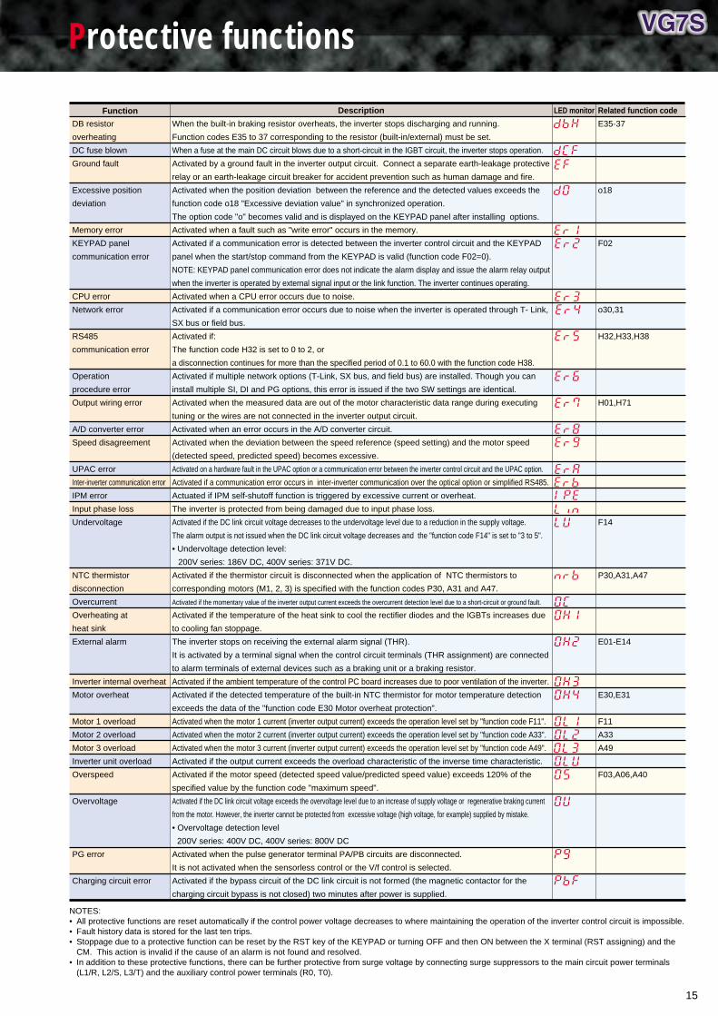
Protective functions
NOTES: • All protective functions are reset automatically if the control power voltage decreases to where maintaining the operation of the inverter control circuit is impossible.• Fault history data is stored for the last ten trips.• Stoppage due to a protective function can be reset by the RST key of the KEYPAD or turning OFF and then ON between the X terminal (RST assigning) and the
CM. This action is invalid if the cause of an alarm is not found and resolved.• In addition to these protective functions, there can be further protective from surge voltage by connecting surge suppressors to the main circuit power terminals
(L1/R, L2/S, L3/T) and the auxiliary control power terminals (R0, T0).
LED monitor
When the built-in braking resistor overheats, the inverter stops discharging and running.
Function codes E35 to 37 corresponding to the resistor (built-in/external) must be set.
When a fuse at the main DC circuit blows due to a short-circuit in the IGBT circuit, the inverter stops operation.
Activated by a ground fault in the inverter output circuit. Connect a separate earth-leakage protective
relay or an earth-leakage circuit breaker for accident prevention such as human damage and fire.
Activated when the position deviation between the reference and the detected values exceeds the
function code o18 "Excessive deviation value" in synchronized operation.
The option code "o" becomes valid and is displayed on the KEYPAD panel after installing options.
Activated when a fault such as "write error" occurs in the memory.
Activated if a communication error is detected between the inverter control circuit and the KEYPAD
panel when the start/stop command from the KEYPAD is valid (function code F02=0).
NOTE: KEYPAD panel communication error does not indicate the alarm display and issue the alarm relay output
when the inverter is operated by external signal input or the link function. The inverter continues operating.
Activated when a CPU error occurs due to noise.
Activated if a communication error occurs due to noise when the inverter is operated through T- Link,
SX bus or field bus.
Activated if:
The function code H32 is set to 0 to 2, or
a disconnection continues for more than the specified period of 0.1 to 60.0 with the function code H38.
Activated if multiple network options (T-Link, SX bus, and field bus) are installed. Though you can
install multiple SI, DI and PG options, this error is issued if the two SW settings are identical.
Activated when the measured data are out of the motor characteristic data range during executing
tuning or the wires are not connected in the inverter output circuit.
Activated when an error occurs in the A/D converter circuit.
Activated when the deviation between the speed reference (speed setting) and the motor speed
(detected speed, predicted speed) becomes excessive.
Activated on a hardware fault in the UPAC option or a communication error between the inverter control circuit and the UPAC option.
Activated if a communication error occurs in inter-inverter communication over the optical option or simplified RS485.
Actuated if IPM self-shutoff function is triggered by excessive current or overheat.
The inverter is protected from being damaged due to input phase loss.
Activated if the DC link circuit voltage decreases to the undervoltage level due to a reduction in the supply voltage.
The alarm output is not issued when the DC link circuit voltage decreases and the "function code F14" is set to "3 to 5".
• Undervoltage detection level:
200V series: 186V DC, 400V series: 371V DC.
Activated if the thermistor circuit is disconnected when the application of NTC thermistors to
corresponding motors (M1, 2, 3) is specified with the function codes P30, A31 and A47.
Activated if the momentary value of the inverter output current exceeds the overcurrent detection level due to a short-circuit or ground fault.
Activated if the temperature of the heat sink to cool the rectifier diodes and the IGBTs increases due
to cooling fan stoppage.
The inverter stops on receiving the external alarm signal (THR).
It is activated by a terminal signal when the control circuit terminals (THR assignment) are connected
to alarm terminals of external devices such as a braking unit or a braking resistor.
Activated if the ambient temperature of the control PC board increases due to poor ventilation of the inverter.
Activated if the detected temperature of the built-in NTC thermistor for motor temperature detection
exceeds the data of the "function code E30 Motor overheat protection".
Activated when the motor 1 current (inverter output current) exceeds the operation level set by "function code F11".
Activated when the motor 2 current (inverter output current) exceeds the operation level set by "function code A33".
Activated when the motor 3 current (inverter output current) exceeds the operation level set by "function code A49".
Activated if the output current exceeds the overload characteristic of the inverse time characteristic.
Activated if the motor speed (detected speed value/predicted speed value) exceeds 120% of the
specified value by the function code "maximum speed".
Activated if the DC link circuit voltage exceeds the overvoltage level due to an increase of supply voltage or regenerative braking current
from the motor. However, the inverter cannot be protected from excessive voltage (high voltage, for example) supplied by mistake.
• Overvoltage detection level
200V series: 400V DC, 400V series: 800V DC
Activated when the pulse generator terminal PA/PB circuits are disconnected.
It is not activated when the sensorless control or the V/f control is selected.
Activated if the bypass circuit of the DC link circuit is not formed (the magnetic contactor for the
charging circuit bypass is not closed) two minutes after power is supplied.
DB resistor
overheating
DC fuse blown
Ground fault
Excessive position
deviation
Memory error
KEYPAD panel
communication error
CPU error
Network error
RS485
communication error
Operation
procedure error
Output wiring error
A/D converter error
Speed disagreement
UPAC error
Inter-inverter communication error
IPM error
Input phase loss
Undervoltage
NTC thermistor
disconnection
Overcurrent
Overheating at
heat sink
External alarm
Inverter internal overheat
Motor overheat
Motor 1 overload
Motor 2 overload
Motor 3 overload
Inverter unit overload
Overspeed
Overvoltage
PG error
Charging circuit error
Related function code
E35-37
o18
F02
o30,31
H32,H33,H38
H01,H71
F14
P30,A31,A47
E01-E14
E30,E31
F11
A33
A49
F03,A06,A40
Function Description

16
External Dimensions
W
W1
C
D2
D
H1
H4
H2
H5
H
W1
H1
4-Bolt
2-øC W
W1
C
D3
D1
H1
H4
H2
H5
H
W1
W4
W2
W5
H9
H6
H3
H7
H8
4-Bolt
2-øC
Panel drilling
RUN
REMOTE/LOCAL
JOG/NORMAL
FWD
Hz A V % s/min
REV STOP REM LOC COMM JOG
PRG FWD
RESET
REV
STOP
SHIFT
FUNCDATA
m/min kW X10 X100
WW1
W3
W1
W3
H1
H4
H2
H5
H1
H
D2
D
D1
C
2or3-øC
4-ø18Lifting hole
2or6- Bolt
Panel drilling
WW1
W3
W2W1
W3
H1
H4
H2
H5
H3
H1
H6
H
D2
D1
C
2or3-øC
4-ø18Lifting hole
2or6-Bolt
Panel cutting
78.664
2-M3×17(Supplied)
7.317.5 6.8
4.77.3
126.
8
100.
426
.4
115
5.9
5.9
7.2
64±0.3
Mounting hole positions for KEYPAD panel
2-M3(ø3.5 for nut)
43±0.5
28.350.31111 ø35
115 ±
0.3
20.5
±0.5
W DD1W1
W3 W4
H1
H5
H2
H6
D4
D3
H7
H
C
D23or4-øC
4-ø35Lifting bolt
Panel drilling for internal mounting type Stand alone type
Panel cutting for external cooling type
W1
W5
W3 W4
H1
6 or 8-Bolt 4-øC
W1
W2
W3 W4
H1
H3
6 or 8-Bolt
D1D2
D1D2
H7
W1
W2
W3 W4
H4
7 or 8-Bolt
D6
D5
Note: Optional adapter required
Panel cutting
Fig. C (Internal mounting type)
Fig. A (Internal mounting type) Fig. B (External cooling type)
Fig. D (External cooling type) KEYPAD panel (Common to all models)
Fig. E (Type common to internal mounting, external cooling, and stand alone)
External Dimensions

17
Nominal applied motor
[kW]Inverter type
Inverter type
W1W W2
0.75
1.5
2.2
3.7
5.5
7.5
11
15
18.5
22
30
37
45
55
75
90
FRN0.75VG7S-2
FRN1.5VG7S-2
FRN2.2VG7S-2
FRN3.7VG7S-2
FRN5.5VG7S-2
FRN7.5VG7S-2
FRN11VG7S-2
FRN15VG7S-2
FRN18.5VG7S-2
FRN22VG7S-2
FRN30VG7S-2
FRN37VG7S-2
FRN45VG7S-2
FRN55VG7S-2
FRN75VG7S-2
FRN90VG7S-2
205
250
340
375
530
680
A
•
B
C
•
D
181
226
240
275
430
580
207
252
326
361
510
660
W3
–
–
265
W4
197
242
–
W5
159
202
–
H
300
380
480
550
615
740
750
880
H1
278
358
460
530
595
720
720
850
H2
255
335
430
500
565
690
685
815
H3
314
394
442
512
577
702
695
825
H4
11
12
15.5
H5
21
25
32.5
H6
253.5
333.5
9
12.5
H7
39
–
H8
8
–
H9
315
395
–
D
245
255
270
285
360
D1
125
145
145
220
D2
10
4
D3
7
–
C
10
10
15
M8
M8
M12
8
12.5
25
30
37
46
48
70
115
Mtg. bolt
Approx. mass [kg]
NOTE: Since the DC REACTOR for power-factor correction is equipped with inverter unit (supplied for external installation) of 75kW or more as standard, reserve installation space outside of the unit.
200V series
400V series
Dimensions [mm]
Nominal applied motor
[kW] W1W W2
3.7
5.5
7.5
11
15
18.5
22
30
37
45
55
75
90
110
132
160
200
220
280
315
355
400
FRN3.7VG7S-4
FRN5.5VG7S-4
FRN7.5VG7S-4
FRN11VG7S-4
FRN15VG7S-4
FRN18.5VG7S-4
FRN22VG7S-4
FRN30VG7S-4
FRN37VG7S-4
FRN45VG7S-4
FRN55VG7S-4
FRN75VG7S-4
FRN90VG7S-4
FRN110VG7S-4
FRN132VG7S-4
FRN160VG7S-4
FRN200VG7S-4
FRN220VG7S-4
FRN280VG7S-4
FRN315G7S-4
FRN355VG7S-4
FRN400VG7S-4
205
250
340
375
530
680
680
880
A
•
B
C
•
D
E
181
226
240
275
430
580
580
780
207
252
326
361
510
660
660
860
W3
–
–
290
290
260
W4
197
242
–
–
260
W5
159
202
–
610
810
H
300
380
480
550
675
740
740
1000
1400
H1
278
358
460
530
655
720
710
970
1370
H2
255
335
430
500
625
690
675
935
1330
H3
314
394
442
512
637
702
685
945
1340
H4
11
12
15.5
1335
H5
21
25
32.5
15.5
H6
253.5
333.5
9
12.5
3.5
H7
39
–
14.5
H8
8
–
–
H9
315
395
–
–
D
245
255
270
315
360
450
D1
125
145
175
220
285
D2
10
4
6.4
D3
7
–
50
C
10
10
15
15
M8
M8
M12
M12
8
12.5
25
30
35
40
41
50
72
100
140
250
360
Dimensions [mm]
D4
–
–
100
D5
–
–
35
D6
–
–
115
Fig.
Fig.
Since the 18.5kW or larger model can be modified to external cooling type by replacing the mounting bracket, the adapter is not required.
Mounting adapter for external cooling (optional for models of 15kW or less)
PBVG7-7.5
PBVG7-15
FRN0.75VG7S-2 to FRN7.5VG7S-2
FRN3.7VG7S-4 to FRN7.5VG7S-4
FRN11VG7S-2, FRN15VG7S-2
FRN11VG7S-4, FRN15VG7S-4
Applicable inverter type Option type
Approx. mass [kg]
Mtg. bolt
18
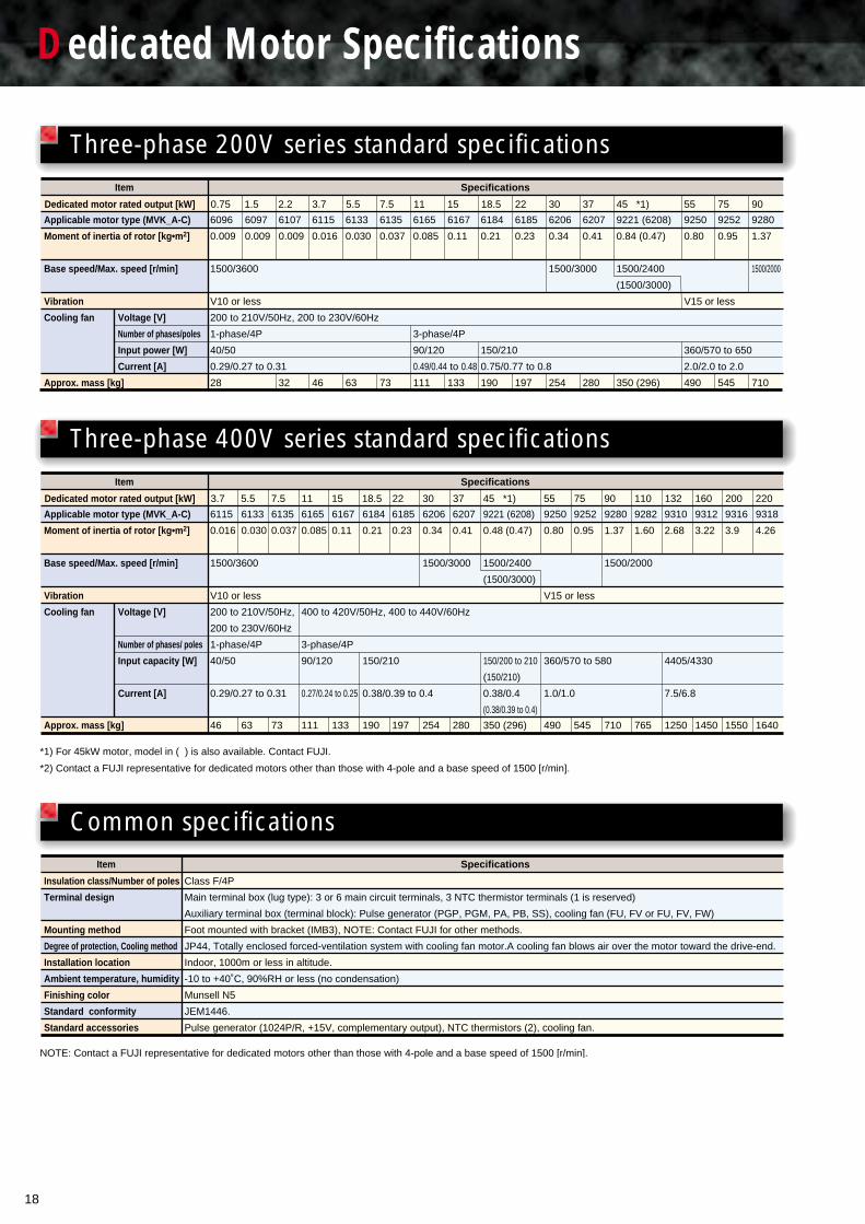
Dedicated Motor Specifications
Dedicated motor rated output [kW] 0.75 1.5 2.2 3.7 5.5 7.5 11 15 18.5 22 30 37 45 *1) 55 75 90
Applicable motor type (MVK_A-C)
Moment of inertia of rotor [kg•m2]
Base speed/Max. speed [r/min]
Vibration
Cooling fan
Approx. mass [kg]
6096
0.009
1500/3600
V10 or less
200 to 210V/50Hz, 200 to 230V/60Hz
1-phase/4P
40/50
0.29/0.27 to 0.31
28
6097
0.009
6107
0.009
32
6115
0.016
46
6133
0.030
63
6135
0.037
73
6165
0.085
3-phase/4P
90/120
0.49/0.44 to 0.48
111
6167
0.11
133
6184
0.21
150/210
0.75/0.77 to 0.8
190
6185
0.23
197
6206
0.34
1500/3000
254
6207
0.41
280
9221 (6208)
0.84 (0.47)
1500/2400
(1500/3000)
350 (296)
9250
0.80
V15 or less
360/570 to 650
2.0/2.0 to 2.0
490
9252
0.95
545
9280
1.37
1500/2000
710
Voltage [V]
Number of phases/poles
Input power [W]
Current [A]
Dedicated motor rated output [kW] 3.7 5.5 7.5 11 15 18.5 22 30 37 45 *1) 55 75 90 110 132 160 200 220
6133
0.030
63
6135
0.037
73
6165
0.085
400 to 420V/50Hz, 400 to 440V/60Hz
3-phase/4P
90/120
0.27/0.24 to 0.25
111
6167
0.11
133
6184
0.21
150/210
0.38/0.39 to 0.4
190
6185
0.23
197
6207
0.41
280
9250
0.80
V15 or less
360/570 to 580
1.0/1.0
490
9252
0.95
545
9282
1.60
765
9310
2.68
4405/4330
7.5/6.8
1250
9312
3.22
1450
9316
3.9
1550
9318
4.26
1640
Voltage [V]
Number of phases/ poles
Input capacity [W]
Current [A]
*1) For 45kW motor, model in ( ) is also available. Contact FUJI.
*2) Contact a FUJI representative for dedicated motors other than those with 4-pole and a base speed of 1500 [r/min].
NOTE: Contact a FUJI representative for dedicated motors other than those with 4-pole and a base speed of 1500 [r/min].
Item Specifications
Item Specifications
Insulation class/Number of poles
Terminal design
Mounting method
Degree of protection, Cooling method
Installation location
Ambient temperature, humidity
Finishing color
Standard conformity
Standard accessories
Item
Class F/4P
Main terminal box (lug type): 3 or 6 main circuit terminals, 3 NTC thermistor terminals (1 is reserved)
Auxiliary terminal box (terminal block): Pulse generator (PGP, PGM, PA, PB, SS), cooling fan (FU, FV or FU, FV, FW)
Foot mounted with bracket (IMB3), NOTE: Contact FUJI for other methods.
JP44, Totally enclosed forced-ventilation system with cooling fan motor.A cooling fan blows air over the motor toward the drive-end.
Indoor, 1000m or less in altitude.
-10 to +40˚C, 90%RH or less (no condensation)
Munsell N5
JEM1446.
Pulse generator (1024P/R, +15V, complementary output), NTC thermistors (2), cooling fan.
Applicable motor type (MVK_A-C)
Moment of inertia of rotor [kg•m2]
Base speed/Max. speed [r/min]
Vibration
Cooling fan
Approx. mass [kg]
6115
0.016
1500/3600
V10 or less
200 to 210V/50Hz,
200 to 230V/60Hz
1-phase/4P
40/50
0.29/0.27 to 0.31
46
6206
0.34
1500/3000
254
9221 (6208)
0.48 (0.47)
1500/2400
(1500/3000)
150/200 to 210
(150/210)
0.38/0.4
(0.38/0.39 to 0.4)
350 (296)
9280
1.37
1500/2000
710
Three-phase 200V series standard specifications
Three-phase 400V series standard specifications
Common specifications Specifications
19
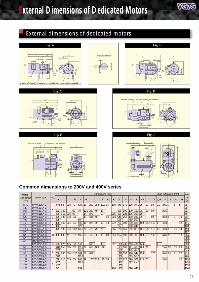
External Dimensions of Dedicated Motors
Common dimensions to 200V and 400V series
Motor rated output
[kW] Motor type Fig.
Dimensions [mm] Shaft extension [mm]
A C D E F G I J K KD KL L M N R XB Z Q QR S T U W
Approx. mass
[kg]
0.751.52.23.75.57.5111518.522303745
557590110132160200220
MVK6096A-CMVK6097A-CMVK6107A-CMVK6115A-CMVK6133A-CMVK6135A-CMVK6165A-CMVK6167A-CMVK6184A-CMVK6185A-CMVK6206A-CMVK6207A-C(MVK6208A-C)MVK9221A-CMVK9250A-CMVK9252A-CMVK9280A-CMVK9282A-CMVK9310A-CMVK9312A-CMVK9316A-CMVK9318A-C
A
B
A
C
D
E
F
277.5
292299309328400422425
490
593693.5712.5766790.5798822.5922.5947
90
100112132
160
180
200
225250
280
315
203
236273
321
376
411
475535
605
675
70
8095108
127
139.5
159
178203
228.5
254
62.5
70
89105127120.5
152.5
143155.5174.5184209.5203228.5
254
10
12.51417
18
20
25
30
35
42
229
238270311
376
428
466
515653
807
1367
35.5
40
45
50
75
80
100
120
35.5
4050
63
75
85
95120
145
27
34
48
80
90
190
205223
272
305
364
387
460
446
485499548586723767776.5
915.5
102511571195131013601387143715371587
170
195224250
300
350
390
436506
557
628
150
170175180212250300292
360
366411449468519526577
628
168.5
193200239258323345351.5
425.5
432463.5482.5544569.5589614.5
640
56
637089
108
121
133
149168
190
216
10
12
14.5
14.5
18.5
24
28
50
60
80
110
110
140
170
0.5
1
1.5
2
12
24j6
28j6
38k6
42k6
48k6
60m6
75m6
85m6
95m6
7
8
9
11
12
14
4
5
5.5
7
7.5
9
8
10
12
14
18
20
22
25
2828324663731111331901972542802963504905457107651250145015501640
J Z
E E
M
XB
N
FF
K
ØKDQR
Main terminal box
∗
Aux. terminal box
2-Ø22
2-Ø22
(L&R)
D
KL
L
RA
Q
C0
-0.5
G
I
102
AIR
T
U
SW
Shaft extension
J
M
XB
N
K
ØKDQR
Main terminal boxAux. terminal box
2-Ø222-Ø22
(L&R)
D
KL
RA
Q
C0
-0.5
G
I
102
Z
E EFF
∗AIR
ØKDQR
Main terminal boxAux. terminal box
2-Ø22
2-Ø22
(L&R)
D
KL
L
RA
Q
C0
-0.5
G
I
102
J Z
E E
M
XB
N
FF
K
AIR
317KDQR
Main terminal boxAux. terminal box (for PG)Aux. terminal box (for fan)
Ø22 Ø22 Ø22
D
KL
L
RA
Q
C0
-0.5
168
G
I
AIR
XB
N
FF
K J Z
E E
M
QR
Main terminal box
DL
RA
Q
C0
-0.5
G
I
AIR
Ø22Ø22 KDØ22
Aux. terminal box (for PG)Aux. terminal box (for fan)
XB
N
FF
K J Z
E E
M
JZ
E E
M
QR
Main terminal box
Ø22KD
Ø22
Ø22
Aux. terminal box (for PG)
D
KL
LR
201
A
Q
C0 -1
G
I
AIR
Aux. terminal box (for fan)
XB
N
FF
K
A bushing to fill the cable hole is attached on the right side of the main terminal box (indicated by ).
Fig. A Fig. B
Fig. C Fig. D
Fig. E Fig. F
External dimensions of dedicated motors
∗
20
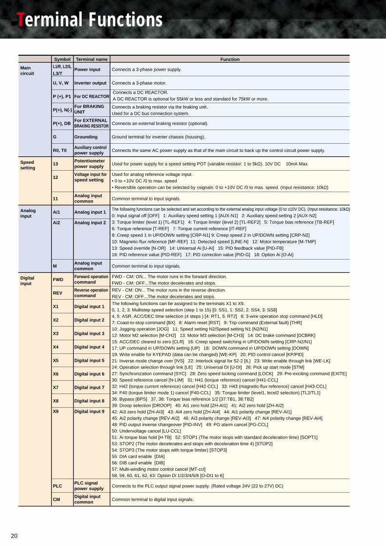
Terminal Functions
Speedsetting
Analoginput
Digitalinput
L1/R, L2/S,
L3/T
U, V, W Connects a 3-phase motor.
Connects an external braking resistor (optional).
Ground terminal for inverter chassis (housing).
Connects the same AC power supply as that of the main circuit to back up the control circuit power supply.
Connects a 3-phase power supply.
Connects a DC REACTOR.A DC REACTOR is optional for 55kW or less and standard for 75kW or more.
Connects a braking resistor via the braking unit.Used for a DC bus connection system.
P (+), P1
P(+), N(-)
P(+), DB
G
R0, T0
Inverter output
For DC REACTOR
For BRAKINGUNIT
For EXTERNALBRAKING RESISTOR
Grounding
Used for power supply for a speed setting POT (variable resistor: 1 to 5kΩ). 10V DC 10mA Max.13Potentiometerpower supply
Used for analog reference voltage input.• 0 to +10V DC /0 to max. speed• Reversible operation can be selected by ±signals: 0 to +10V DC /0 to max. speed. (Input resistance: 10kΩ)
12Voltage input forspeed setting
Common terminal to input signals.11Analog inputcommon
The following functions can be selected and set according to the external analog input voltage (0 to ±10V DC). (Input resistance: 10kΩ)0: Input signal off [OFF] 1: Auxiliary speed setting 1 [AUX-N1] 2: Auxiliary speed setting 2 [AUX-N2]3: Torque limiter (level 1) [TL-REF1] 4: Torque limiter (level 2) [TL-REF2] 5: Torque bias reference [TB-REF]6: Torque reference [T-REF] 7: Torque current reference [IT-REF]8: Creep speed 1 in UP/DOWN setting [CRP-N1] 9: Creep speed 2 in UP/DOWN setting [CRP-N2] 10: Magnetic-flux reference [MF-REF] 11: Detected speed [LINE-N] 12: Motor temperature [M-TMP] 13: Speed override [N-OR] 14: Universal Ai [U-AI] 15: PID feedback value [PID-FB] 16: PID reference value [PID-REF] 17: PID correction value [PID-G] 18: Option Ai [O-AI]
Ai1 Analog input 1
Ai2 Analog input 2
MAnalog inputcommon
FWD - CM: ON... The motor runs in the forward direction.FWD - CM: OFF...The motor decelerates and stops.
Common terminal to input signals.
FWDForward operationcommand
REV - CM: ON... The motor runs in the reverse direction.REV - CM: OFF...The motor decelerates and stops.
REVReverse operationcommand
The following functions can be assigned to the terminals X1 to X9.0, 1, 2, 3: Multistep speed selection (step 1 to 15) [0: SS1, 1: SS2, 2: SS4, 3: SS8]4, 5: ASR, ACC/DEC time selection (4 steps ) [4: RT1, 5: RT2] 6: 3-wire operation stop command [HLD]7: Coast-to-stop command [BX] 8: Alarm reset [RST] 9: Trip command (External fault) [THR]10: Jogging operation [JOG] 11: Speed setting N2/Speed setting N1 [N2/N1]12: Motor M2 selection [M-CH2] 13: Motor M3 selection [M-CH3] 14: DC brake command [DCBRK]15: ACC/DEC cleared to zero [CLR] 16: Creep speed switching in UP/DOWN setting [CRP-N2/N1]17: UP command in UP/DOWN setting [UP] 18: DOWN command in UP/DOWN setting [DOWN]19: Write enable for KYEPAD (data can be changed) [WE-KP] 20: PID control cancel [KP/PID]21: Inverse mode change over [IVS] 22: Interlock signal for 52-2 [IL] 23: Write enable through link [WE-LK]24: Operation selection through link [LE] 25: Universal DI [U-DI] 26: Pick up start mode [STM]27: Synchronization command [SYC] 28: Zero speed locking command [LOCK] 29: Pre-exciting command [EXITE]30: Speed reference cancel [N-LIM] 31: H41 (torque reference) cancel [H41-CCL]32: H42 (torque current reference) cancel [H42-CCL] 33: H43 (magnetic-flux reference) cancel [H43-CCL]34: F40 (torque limiter mode 1) cancel [F40-CCL] 35: Torque limiter (level1, lecel2 selection) [TL2/TL1]36: Bypass [BPS] 37, 38: Torque bias reference 1/2 [37:TB1, 38:TB2]39: Droop selection [DROOP] 40: Ai1 zero hold [ZH-AI1] 41: Ai2 zero hold [ZH-AI2]42: Ai3 zero hold [ZH-AI3] 43: Ai4 zero hold [ZH-AI4] 44: Ai1 polarity change [REV-AI1]45: Ai2 polarity change [REV-AI2] 46: Ai3 polarity change [REV-AI3] 47: Ai4 polarity change [REV-AI4]48: PID output inverse changeover [PID-INV] 49: PG alarm cancel [PG-CCL]50: Undervoltage cancel [LU-CCL]51: Ai torque bias hold [H-TB] 52: STOP1 (The motor stops with standard deceleration time) [SOPT1]53: STOP2 (The motor decelerates and stops with deceleration time 4) [STOP2] 54: STOP3 (The motor stops with torque limiter) [STOP3]55: DIA card enable [DIA]56: DIB card enable [DIB]57: Multi-winding motor control cancel [MT-ccl]58, 59, 60, 61, 62, 63: Option Di 1/2/3/4/5/6 [O-DI1 to 6]
X1 Digital input 1
X2 Digital input 2
X3 Digital input 3
X4 Digital input 4
X5 Digital input 5
X6 Digital input 6
X7 Digital input 7
X8 Digital input 8
X9 Digital input 9
Connects to the PLC output signal power supply. (Rated voltage 24V (22 to 27V) DC)PLCPLC signalpower supply
Common terminal to digital input signals.CMDigital inputcommon
Auxiliary controlpower supply
Power inputMain circuit
FunctionSymbol Terminal name
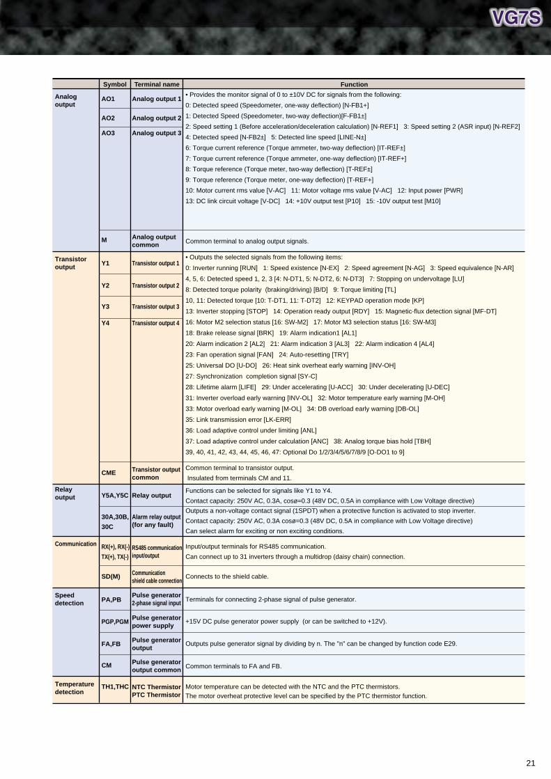
21
• Provides the monitor signal of 0 to ±10V DC for signals from the following:
0: Detected speed (Speedometer, one-way deflection) [N-FB1+]
1: Detected Speed (Speedometer, two-way deflection)[F-FB1±]
2: Speed setting 1 (Before acceleration/deceleration calculation) [N-REF1] 3: Speed setting 2 (ASR input) [N-REF2]
4: Detected speed [N-FB2±] 5: Detected line speed [LINE-N±]
6: Torque current reference (Torque ammeter, two-way deflection) [IT-REF±]
7: Torque current reference (Torque ammeter, one-way deflection) [IT-REF+]
8: Torque reference (Torque meter, two-way deflection) [T-REF±]
9: Torque reference (Torque meter, one-way deflection) [T-REF+]
10: Motor current rms value [V-AC] 11: Motor voltage rms value [V-AC] 12: Input power [PWR]
13: DC link circuit voltage [V-DC] 14: +10V output test [P10] 15: -10V output test [M10]
Analog output 1Analogoutput
FunctionSymbol Terminal name
Analog output 2AO2
AO1
Analog output 3AO3
Transistoroutput
Common terminal to analog output signals.Analog outputcommon
M
• Outputs the selected signals from the following items:
0: Inverter running [RUN] 1: Speed existence [N-EX] 2: Speed agreement [N-AG] 3: Speed equivalence [N-AR]
4, 5, 6: Detected speed 1, 2, 3 [4: N-DT1, 5: N-DT2, 6: N-DT3] 7: Stopping on undervoltage [LU]
8: Detected torque polarity (braking/driving) [B/D] 9: Torque limiting [TL]
10, 11: Detected torque [10: T-DT1, 11: T-DT2] 12: KEYPAD operation mode [KP]
13: Inverter stopping [STOP] 14: Operation ready output [RDY] 15: Magnetic-flux detection signal [MF-DT]
16: Motor M2 selection status [16: SW-M2] 17: Motor M3 selection status [16: SW-M3]
18: Brake release signal [BRK] 19: Alarm indication1 [AL1]
20: Alarm indication 2 [AL2] 21: Alarm indication 3 [AL3] 22: Alarm indication 4 [AL4]
23: Fan operation signal [FAN] 24: Auto-resetting [TRY]
25: Universal DO [U-DO] 26: Heat sink overheat early warning [INV-OH]
27: Synchronization completion signal [SY-C]
28: Lifetime alarm [LIFE] 29: Under accelerating [U-ACC] 30: Under decelerating [U-DEC]
31: Inverter overload early warning [INV-OL] 32: Motor temperature early warning [M-OH]
33: Motor overload early warning [M-OL] 34: DB overload early warning [DB-OL]
35: Link transmission error [LK-ERR]
36: Load adaptive control under limiting [ANL]
37: Load adaptive control under calculation [ANC] 38: Analog torque bias hold [TBH]
39, 40, 41, 42, 43, 44, 45, 46, 47: Optional Do 1/2/3/4/5/6/7/8/9 [O-DO1 to 9]
Transistor output 1Y1
Transistor output 2Y2
Transistor output 3Y3
Transistor output 4Y4
Relayoutput
Communication
Speeddetection
Temperaturedetection
Common terminal to transistor output.
Insulated from terminals CM and 11.Transistor outputcommon
CME
Functions can be selected for signals like Y1 to Y4.
Contact capacity: 250V AC, 0.3A, cosø=0.3 (48V DC, 0.5A in compliance with Low Voltage directive)Relay outputY5A,Y5C
Outputs a non-voltage contact signal (1SPDT) when a protective function is activated to stop inverter.
Contact capacity: 250V AC, 0.3A cosø=0.3 (48V DC, 0.5A in compliance with Low Voltage directive)
Can select alarm for exciting or non exciting conditions.
Alarm relay output(for any fault)
30A,30B,
30C
Input/output terminals for RS485 communication.
Can connect up to 31 inverters through a multidrop (daisy chain) connection.RS485 communicationinput/output
RX(+), RX(-)
TX(+), TX(-)
Connects to the shield cable.Communicationshield cable connection
SD(M)
Terminals for connecting 2-phase signal of pulse generator.Pulse generator2-phase signal inputPA,PB
+15V DC pulse generator power supply (or can be switched to +12V).Pulse generatorpower supply
PGP,PGM
Outputs pulse generator signal by dividing by n. The "n" can be changed by function code E29.Pulse generatoroutput
FA,FB
Common terminals to FA and FB.Pulse generatoroutput common
CM
Motor temperature can be detected with the NTC and the PTC thermistors.The motor overheat protective level can be specified by the PTC thermistor function.
NTC ThermistorPTC Thermistor
TH1,THC
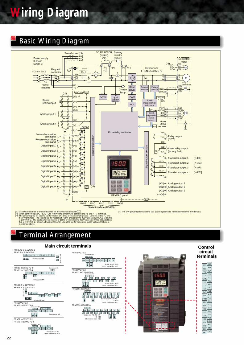
22
Wiring Diagram
Basic Wiring DiagramTransformer (*3)
FU
G P1(*2)
DC REACTOR (option)
(*2)
Brakingresistor(option)
Inverter unitFRENIC5000VG7S
Basedriver
PWM
ACR
Currentdetector
Voltagedetector
Speedmagnetic-flux
calculator
Processing controller
KEYPAD panel
Speed/magnetic-flux
positiondetector
Linkcircuit
voltagedetector
Chargelamp
DC/DC
P(+) N(-)DB
WVU
W
TH2TH1(TH1)
(THC) THC
VU
SAL1/R
R
F
C ML2/SL3/T
R0T0
FVFW
MCCB or ELCBMagnetic contactor
ACreactor(option)
Power supply3-phase50/60Hz (*3)
Dedicatedmotor
FUFVFW
FU
FMFVFW
PGMPAPBSS.E
PGP
(PA)(PB)
(PGM)(PGP)
PG
(FA)(FB)(CM)
Y5A
Relay output[RDY]
Serial interface (RS485)
Y5C
30C
Alarm relay output (for any fault)
Transistor output 1 [N-EX]
Transistor output 2 [N-AG]
Transistor output 3 [N-AR]
Transistor output 4 [N-DTI]
Analog output 1
Analog output 2
Analog output 3
30B
30A30
<Y1>
<Y2>
<Y3>
<Y4>
<CME>
[A01]
[A02]
[A03]
[M]
0V
0V
0V
0V
E
(*4)
(CM)
RX(+) RX(–) TX(+) TX(–) SD(M)
(X5)Digital input 5
(X6)Digital input 6
(X7)Digital input 7
(X8)Digital input 8
(X9)Digital input 9
(X4)Digital input 4
(X3)Digital input 3
(X2)Digital input 2
(X1)Digital input 1
(REV)Reverse operationcommand
(FWD)
PLC
[M]
[Ai2]
(Ai1)
(13)
+DC24V
15V 12V
SW5
+DC10V
Forward operationcommand
(12)
(11)
Analog input 1
Speedsetting input
Analog input 2
(*1)
FRN75VG7S-2FRN0.75 to 7.5VG7S-2FRN3.7 to 7.5VG7S-4
FRN90VG7S-2FRN132 to 220VG7S-4
FRN280, 315VG7S-4
G G
L1/R L2/S L3/T DB P1 P(+) N(-) U V W
FRN11 to 15VG7S-2FRN11 to 15VG7S-4
FRN18.5 to 22VG7S-2FRN18.5 to 22VG7S-4
FRN30VG7S-2FRN30 to 55VG7S-4
L1/R L2/S L3/T P1 P(+) N(-) U V W
Screw size: M5R0
T0
Scr
ew s
ize:
M4
Screw size: M4
R0 T0
G
GDB
Screw size: M6
Scr
ew s
ize:
M4
R0T0
L1/R L2/S L3/T
DB P1 P(+)U
N(-)V W
Screw size: M6G G
Screw size: M4
Screw size: M8
L1/R L2/S L3/T P1
U V W
P(+) DB N(-)R0 T0
G G
Screw size: M4
R0 T0
L1/R L2/S L3/T P1 P(+) N(-) U V W
Screw size G: M10Other screw size: M12
Screw size G: M10Other screw size: M12
G G
Screw size: M4
R0 T0
L1/R U V WL2/S L3/T
P(+) N(-)P1
G G
Screw size R0, T0: M4 G: M10
Other screw size: M12
R0 T0
L1/R
L1/R
P1 P(+) N(-)L2/S L3/T
L2/S L3/T P(+) N(-)
U V
U V
W
WP1
G G
FRN355, 400VG7S-4
Screw size R0, T0: M4 G: M10
Other screw size: M12
R0 T0
L1/R
L1/R
P1 P(+) N(-)L2/S L3/T
L2/S L3/T P(+) N(-)
U V
U V
W
WP1
G G
30A30C
30BY5C
Y5AY4
Y3Y2
Y1CME
Ai111
Ai212
M13
Ao1Ao3
Ao2CM
PLCFWD
X1REV
X2CM
X3X6
X4X7
X5X8
PGPX9
PGMFA
PAFB
PBCM
THCTH1
NTCthermistor
Sig
nal i
nput
sec
tion
Sig
nal o
utpu
t sec
tion
(*1) Use twisted cables or shielded cables for the wire indicated with .(*2) When connecting a DC REACTOR, remove the jumper wire between the P1 and P (+) terminals.(*3) The power supply for cooling fan for motors of 7.5kW or less is single-phase. Connect to the FU and
the FV terminals. The cooling fan for models of 7.5kW or less for the 400V series is 200V/50Hz or 200 to 230V/60Hz. The cooling fan for models of 11kW or more for the 400V series is 400 to 420V/50Hz or 400 to 440V/60Hz. Obtain a transformer when using the fan for the power supply voltage that is not mentioned above.
Main circuit terminals Control circuit
terminals
Terminal Arrangement
(*4) The 24V power system and the 15V power system are insulated inside the inverter unit.
0V
FRN37 to 55VG7S-2FRN75 to 110VG7S-4
Screw size: M4
Screw size G: M8 Other screw size: M10
L1/R L2/S L3/T P1
U V W
P(+) DB N(-)R0 T0
G G

Operation Procedures
23
Turn on the inverter, set the speed with the and the keys, press the key, and then press the or the
key to operate the inverter with the function codes set at factory shipment.
Press the key to stop the inverter.
See the Basic wiring diagram on page 22 for the connection.
Names and functions of the KEYPAD panel
KEYPAD panel operation
LED monitorOperation mode:
Displays the setting frequency, output current, output voltage, motor speed, and line speed.
Trip mode:Displays the cause of a trip.
Up/Down keysOperation mode:
Increases or decreases the speed.
Program mode: Changes the function codes and specified data values.
FWD/REV keysOperation mode:
Pressing the FWD or REV key lights the RUN lamp. Invalid when the function code F02 (Operation method) is set to 1 (external signal operation).
LCD monitorDisplays different information ranging from operation status to function data.Operation guidance is displayed scrolling at the bottom.
Unit indicationDisplays the unit for the information that appears on the LED monitor.
Program keySwitches the display to the menu screen or the initial screens for the operation and alarm modes.
Shift key (column shift)Used to move the cursor horizontally for data change and to jump to another function block (when pressed with the UP/DOWN keys)
Function/Data select keyUsed to switch the displayed value of LED monitor, input the speed setting and store the function code data.
Stop keyInvalid when the function code F02 (Operation method) is set to 1 (external signal operation).
Reset keyProgram mode:
Cancels the current input data and changes the screen.
Trip mode: Releases from a trip stoppage.
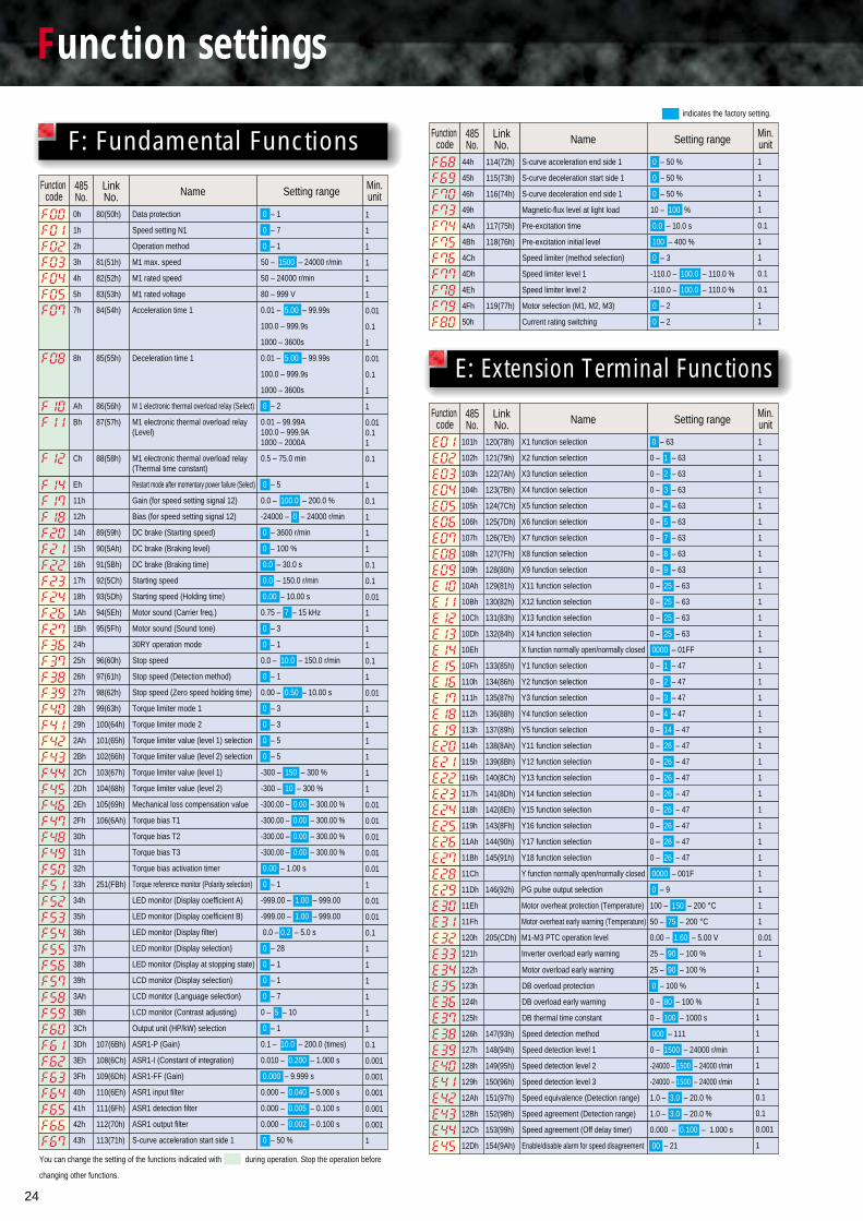
24
Function settings
Name Setting rangeLinkNo.
485No.
Function code
0h
1h
2h
3h
4h
5h
7h
8h
Ah
Bh
Ch
Eh
11h
12h
14h
15h
16h
17h
18h
1Ah
1Bh
24h
25h
26h
27h
28h
29h
2Ah
2Bh
2Ch
2Dh
2Eh
2Fh
30h
31h
32h
33h
34h
35h
36h
37h
38h
39h
3Ah
3Bh
3Ch
3Dh
3Eh
3Fh
40h
41h
42h
43h
80(50h)
81(51h)
82(52h)
83(53h)
84(54h)
85(55h)
86(56h)
87(57h)
88(58h)
89(59h)
90(5Ah)
91(5Bh)
92(5Ch)
93(5Dh)
94(5Eh)
95(5Fh)
96(60h)
97(61h)
98(62h)
99(63h)
100(64h)
101(65h)
102(66h)
103(67h)
104(68h)
105(69h)
106(6Ah)
251(FBh)
107(6Bh)
108(6Ch)
109(6Dh)
110(6Eh)
111(6Fh)
112(70h)
113(71h)
Data protection
Speed setting N1
Operation method
M1 max. speed
M1 rated speed
M1 rated voltage
Acceleration time 1
Deceleration time 1
M 1 electronic thermal overload relay (Select)
M1 electronic thermal overload relay (Level)
M1 electronic thermal overload relay (Thermal time constant)
Restart mode after momentary power failure (Select)
Gain (for speed setting signal 12)
Bias (for speed setting signal 12)
DC brake (Starting speed)
DC brake (Braking level)
DC brake (Braking time)
Starting speed
Starting speed (Holding time)
Motor sound (Carrier freq.)
Motor sound (Sound tone)
30RY operation mode
Stop speed
Stop speed (Detection method)
Stop speed (Zero speed holding time)
Torque limiter mode 1
Torque limiter mode 2
Torque limiter value (level 1) selection
Torque limiter value (level 2) selection
Torque limiter value (level 1)
Torque limiter value (level 2)
Mechanical loss compensation value
Torque bias T1
Torque bias T2
Torque bias T3
Torque bias activation timer
Torque reference monitor (Polarity selection)
LED monitor (Display coefficient A)
LED monitor (Display coefficient B)
LED monitor (Display filter)
LED monitor (Display selection)
LED monitor (Display at stopping state)
LCD monitor (Display selection)
LCD monitor (Language selection)
LCD monitor (Contrast adjusting)
Output unit (HP/kW) selection
ASR1-P (Gain)
ASR1-I (Constant of integration)
ASR1-FF (Gain)
ASR1 input filter
ASR1 detection filter
ASR1 output filter
S-curve acceleration start side 1
44h
45h
46h
49h
4Ah
4Bh
4Ch
4Dh
4Eh
4Fh
50h
114(72h)
115(73h)
116(74h)
117(75h)
118(76h)
119(77h)
S-curve acceleration end side 1
S-curve deceleration start side 1
S-curve deceleration end side 1
Magnetic-flux level at light load
Pre-excitation time
Pre-excitation initial level
Speed limiter (method selection)
Speed limiter level 1
Speed limiter level 2
Motor selection (M1, M2, M3)
Current rating switching
101h
102h
103h
104h
105h
106h
107h
108h
109h
10Ah
10Bh
10Ch
10Dh
10Eh
10Fh
110h
111h
112h
113h
114h
115h
116h
117h
118h
119h
11Ah
11Bh
11Ch
11Dh
11Eh
11Fh
120h
121h
120(78h)
121(79h)
122(7Ah)
123(7Bh)
124(7Ch)
125(7Dh)
126(7Eh)
127(7Fh)
128(80h)
129(81h)
130(82h)
131(83h)
132(84h)
133(85h)
134(86h)
135(87h)
136(88h)
137(89h)
138(8Ah)
139(8Bh)
140(8Ch)
141(8Dh)
142(8Eh)
143(8Fh)
144(90h)
145(91h)
146(92h)
205(CDh)
X1 function selection
X2 function selection
X3 function selection
X4 function selection
X5 function selection
X6 function selection
X7 function selection
X8 function selection
X9 function selection
X11 function selection
X12 function selection
X13 function selection
X14 function selection
X function normally open/normally closed
Y1 function selection
Y2 function selection
Y3 function selection
Y4 function selection
Y5 function selection
Y11 function selection
Y12 function selection
Y13 function selection
Y14 function selection
Y15 function selection
Y16 function selection
Y17 function selection
Y18 function selection
Y function normally open/normally closed
PG pulse output selection
Motor overheat protection (Temperature)
Motor overheat early warning (Temperature)
M1-M3 PTC operation level
Inverter overload early warning
Min.unit
Name Setting rangeLinkNo.
485No.
Function code
Min.unit
Name Setting rangeLinkNo.
485No.
Function code
Min.unit
E: Extension Terminal Functions
122h
123h
124h
125h
126h
127h
128h
129h
12Ah
12Bh
12Ch
12Dh
147(93h)
148(94h)
149(95h)
150(96h)
151(97h)
152(98h)
153(99h)
154(9Ah)
Motor overload early warning
DB overload protection
DB overload early warning
DB thermal time constant
Speed detection method
Speed detection level 1
Speed detection level 2
Speed detection level 3
Speed equivalence (Detection range)
Speed agreement (Detection range)
Speed agreement (Off delay timer)
Enable/disable alarm for speed disagreement
1
1
1
1
1
1
1
1
0.1
0.1
0.001
1
25 – 90 – 100 %
0 – 100 %
0 – 80 – 100 %
0 – 100 – 1000 s
000 – 111
0 – 1500 – 24000 r/min
-24000 – 1500 – 24000 r/min
-24000 – 1500 – 24000 r/min
1.0 – 3.0 – 20.0 %
1.0 – 3.0 – 20.0 %
0.000 – 0.100 – 1.000 s
00 – 21
F: Fundamental Functions
0 – 1
0 – 7
0 – 1
50 – 1500 – 24000 r/min
50 – 24000 r/min
80 – 999 V
0.01 – 5.00 – 99.99s
100.0 – 999.9s
1000 – 3600s
0.01 – 5.00 – 99.99s
100.0 – 999.9s
1000 – 3600s
0 – 2
0.01 – 99.99A100.0 – 999.9A1000 – 2000A
0.5 – 75.0 min
0 – 5
0.0 – 100.0 – 200.0 %
-24000 – 0 – 24000 r/min
0 – 3600 r/min
0 – 100 %
0.0 – 30.0 s
0.0 – 150.0 r/min
0.00 – 10.00 s
0.75 – 7 – 15 kHz
0 – 3
0 – 1
0.0 – 10.0 – 150.0 r/min
0 – 1
0.00 – 0.50 – 10.00 s
0 – 3
0 – 3
0 – 5
0 – 5
-300 – 150 – 300 %
-300 – 10 – 300 %
-300.00 – 0.00 – 300.00 %
-300.00 – 0.00 – 300.00 %
-300.00 – 0.00 – 300.00 %
-300.00 – 0.00 – 300.00 %
0.00 – 1.00 s
0 – 1
-999.00 – 1.00 – 999.00
-999.00 – 1.00 – 999.00
0.0 – 0.2 – 5.0 s
0 – 28
0 – 1
0 – 1
0 – 7
0 – 5 – 10
0 – 1
0.1 – 10.0 – 200.0 (times)
0.010 – 0.200 – 1.000 s
0.000 – 9.999 s
0.000 – 0.040 – 5.000 s
0.000 – 0.005 – 0.100 s
0.000 – 0.002 – 0.100 s
0 – 50 %
0 – 50 %
0 – 50 %
0 – 50 %
10 – 100 %
0.0 – 10.0 s
100 – 400 %
0 – 3
-110.0 – 100.0 – 110.0 %
-110.0 – 100.0 – 110.0 %
0 – 2
0 – 2
0 – 63
0 – 1 – 63
0 – 2 – 63
0 – 3 – 63
0 – 4 – 63
0 – 5 – 63
0 – 7 – 63
0 – 8 – 63
0 – 9 – 63
0 – 25 – 63
0 – 25 – 63
0 – 25 – 63
0 – 25 – 63
0000 – 01FF
0 – 1 – 47
0 – 2 – 47
0 – 3 – 47
0 – 4 – 47
0 – 14 – 47
0 – 26 – 47
0 – 26 – 47
0 – 26 – 47
0 – 26 – 47
0 – 26 – 47
0 – 26 – 47
0 – 26 – 47
0 – 26 – 47
0000 – 001F
0 – 9
100 – 150 – 200 °C
50 – 75 – 200 °C
0.00 – 1.60 – 5.00 V
25 – 90 – 100 %
indicates the factory setting.
You can change the setting of the functions indicated with during operation. Stop the operation before
changing other functions.
1
1
1
1
0.1
1
1
0.1
0.1
1
1
1
1
1
1
1
1
1
1
1
1
1
1
1
1
1
1
1
1
1
1
1
1
1
1
1
1
1
1
1
1
1
0.01
1
1
1
1
1
1
1
0.01
0.1
1
0.01
0.1
1
1
0.010.11
0.1
1
0.1
1
1
1
0.1
0.1
0.01
1
1
1
0.1
1
0.01
1
1
1
1
1
1
0.01
0.01
0.01
0.01
0.01
1
0.01
0.01
0.1
1
1
1
1
1
1
0.1
0.001
0.001
0.001
0.001
0.001
1
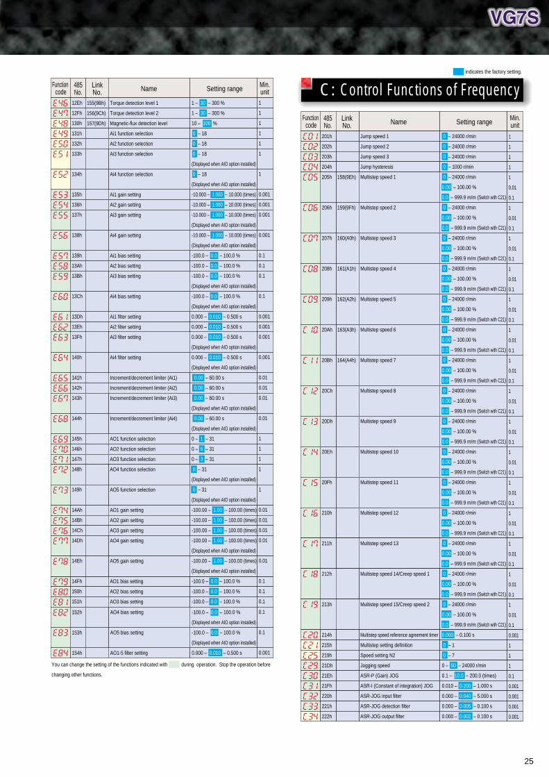
25
indicates the factory setting.
You can change the setting of the functions indicated with during operation. Stop the operation before
changing other functions.
Name Setting rangeLinkNo.
485No.
Function code
Min.unit
155(9Bh)
156(9Ch)
157(9Dh)
Torque detection level 1
Torque detection level 2
Magnetic-flux detection level
Ai1 function selection
Ai2 function selection
Ai3 function selection
Ai4 function selection
Ai1 gain setting
Ai2 gain setting
Ai3 gain setting
Ai4 gain setting
Ai1 bias setting
Ai2 bias setting
Ai3 bias setting
Ai4 bias setting
Ai1 filter setting
Ai2 filter setting
Ai3 filter setting
Ai4 filter setting
Increment/decrement limiter (Ai1)
Increment/decrement limiter (Ai2)
Increment/decrement limiter (Ai3)
Increment/decrement limiter (Ai4)
AO1 function selection
AO2 function selection
AO3 function selection
AO4 function selection
AO5 function selection
AO1 gain setting
AO2 gain setting
AO3 gain setting
AO4 gain setting
AO5 gain setting
AO1 bias setting
AO2 bias setting
AO3 bias setting
12Eh
12Fh
130h
131h
132h
133h
134h
135h
136h
137h
138h
139h
13Ah
13Bh
13Ch
13Dh
13Eh
13Fh
140h
141h
142h
143h
144h
145h
146h
147h
148h
149h
14Ah
14Bh
14Ch
14Dh
14Eh
14Fh
150h
151h
1
1
1
1
1
1
1
0.001
0.001
0.001
0.001
0.1
0.1
0.1
0.1
0.001
0.001
0.001
0.001
0.01
0.01
0.01
0.01
1
1
1
1
1
0.01
0.01
0.01
0.01
0.01
0.1
0.1
0.1
1 – 30 – 300 %
1 – 30 – 300 %
10 – 100 %
0 – 18
0 – 18
0 – 18
(Displayed when AIO option installed)
0 – 18
(Displayed when AIO option installed)
-10.000 – 1.000 – 10.000 (times)
-10.000 – 1.000 – 10.000 (times)
-10.000 – 1.000 – 10.000 (times)
(Displayed when AIO option installed)
-10.000 – 1.000 – 10.000 (times)
(Displayed when AIO option installed)
-100.0 – 0.0 – 100.0 %
-100.0 – 0.0 – 100.0 %
-100.0 – 0.0 – 100.0 %
(Displayed when AIO option installed)
-100.0 – 0.0 – 100.0 %
(Displayed when AIO option installed)
0.000 – 0.010 – 0.500 s
0.000 – 0.010 – 0.500 s
0.000 – 0.010 – 0.500 s
(Displayed when AIO option installed)
0.000 – 0.010 – 0.500 s
(Displayed when AIO option installed)
0.00 – 60.00 s
0.00 – 60.00 s
0.00 – 60.00 s
(Displayed when AIO option installed)
0.00 – 60.00 s
(Displayed when AIO option installed)
0 – 1 – 31
0 – 6 – 31
0 – 3 – 31
0 – 31
(Displayed when AIO option installed)
0 – 31
(Displayed when AIO option installed)
-100.00 – 1.00 – 100.00 (times)
-100.00 – 1.00 – 100.00 (times)
-100.00 – 1.00 – 100.00 (times)
-100.00 – 1.00 – 100.00 (times)
(Displayed when AIO option installed)
-100.00 – 1.00 – 100.00 (times)
(Displayed when AIO option installed)
-100.0 – 0.0 – 100.0 %
-100.0 – 0.0 – 100.0 %
-100.0 – 0.0 – 100.0 %
152h
153h
154h
AO4 bias setting
AO5 bias setting
AO1-5 filter setting
-100.0 – 0.0 – 100.0 %
(Displayed when AIO option installed)
-100.0 – 0.0 – 100.0 %
(Displayed when AIO option installed)
0.000 – 0.010 – 0.500 s
0.1
0.1
0.001
201h
202h
203h
204h
205h
206h
207h
208h
209h
20Ah
20Bh
20Ch
20Dh
20Eh
20Fh
210h
211h
212h
213h
214h
215h
219h
21Dh
21Eh
21Fh
220h
221h
222h
158(9Eh)
159(9Fh)
160(A0h)
161(A1h)
162(A2h)
163(A3h)
164(A4h)
Jump speed 1
Jump speed 2
Jump speed 3
Jump hysteresis
Multistep speed 1
Multistep speed 2
Multistep speed 3
Multistep speed 4
Multistep speed 5
Multistep speed 6
Multistep speed 7
Multistep speed 8
Multistep speed 9
Multistep speed 10
Multistep speed 11
Multistep speed 12
Multistep speed 13
Multistep speed 14/Creep speed 1
Multistep speed 15/Creep speed 2
Multistep speed reference agreement timer
Multistep setting definition
Speed setting N2
Jogging speed
ASR-P (Gain) JOG
ASR-I (Constant of integration) JOG
ASR-JOG input filter
ASR-JOG detection filter
ASR-JOG output filter
0 – 24000 r/min
0 – 24000 r/min
0 – 24000 r/min
0 – 1000 r/min
0 – 24000 r/min
0.00 – 100.00 %
0.0 – 999.9 m/m (Switch with C21)
0 – 24000 r/min
0.00 – 100.00 %
0.0 – 999.9 m/m (Switch with C21)
0 – 24000 r/min
0.00 – 100.00 %
0.0 – 999.9 m/m (Switch with C21)
0 – 24000 r/min
0.00 – 100.00 %
0.0 – 999.9 m/m (Switch with C21)
0 – 24000 r/min
0.00 – 100.00 %
0.0 – 999.9 m/m (Switch with C21)
0 – 24000 r/min
0.00 – 100.00 %
0.0 – 999.9 m/m (Switch with C21)
0 – 24000 r/min
0.00 – 100.00 %
0.0 – 999.9 m/m (Switch with C21)
0 – 24000 r/min
0.00 – 100.00 %
0.0 – 999.9 m/m (Switch with C21)
0 – 24000 r/min
0.00 – 100.00 %
0.0 – 999.9 m/m (Switch with C21)
0 – 24000 r/min
0.00 – 100.00 %
0.0 – 999.9 m/m (Switch with C21)
0 – 24000 r/min
0.00 – 100.00 %
0.0 – 999.9 m/m (Switch with C21)
0 – 24000 r/min
0.00 – 100.00 %
0.0 – 999.9 m/m (Switch with C21)
0 – 24000 r/min
0.00 – 100.00 %
0.0 – 999.9 m/m (Switch with C21)
0 – 24000 r/min
0.00 – 100.00 %
0.0 – 999.9 m/m (Switch with C21)
0 – 24000 r/min
0.00 – 100.00 %
0.0 – 999.9 m/m (Switch with C21)
0.000 – 0.100 s
0 – 1
0 – 7
0 – 50 – 24000 r/min
0.1 – 10.0 – 200.0 (times)
0.010 – 0.200 – 1.000 s
0.000 – 0.040 – 5.000 s
0.000 – 0.005 – 0.100 s
0.000 – 0.002 – 0.100 s
1
1
1
1
1
0.01
0.1
1
0.01
0.1
1
0.01
0.1
1
0.01
0.1
1
0.01
0.1
1
0.01
0.1
1
0.01
0.1
1
0.01
0.1
1
0.01
0.1
1
0.01
0.1
1
0.01
0.1
1
0.01
0.1
1
0.01
0.1
1
0.01
0.1
1
0.01
0.1
0.001
1
1
1
0.1
0.001
0.001
0.001
0.001
Name Setting rangeLinkNo.
485No.
Function code
Min.unit
C: Control Functions of Frequency

26
Function settings
Name Setting rangeLinkNo.
485No.
Function code
Min.unit
Name Setting rangeLinkNo.
485No.
Function code
Min.unit
indicates the factory setting.
Min.unit
301h
302h
303h
304h
305h
306h
307h
308h
309h
30Ah
30Bh
30Ch
30Dh
30Eh
30Fh
310h
311h
312h
313h
314h
315h
316h
317h
318h
319h
31Ah
31Bh
31Ch
31Dh
31Eh
167(A7h)
168(A8h)
169(A9h)
170(AAh)
171(ABh)
172(ACh)
173(ADh)
174(AEh)
175(AFh)
176(B0h)
177(B1h)
178(B2h)
179(B3h)
180(B4h)
181(B5h)
182(B6h)
183(B7h)
184(B8h)
185(B9h)
186(BAh)
187(BBh)
188(BCh)
189(BDh)
190(BEh)
191(BFh)
192(C0h)
214(D6h)
193(C1h)
M1 control method
M1 motor selection
M1 rated capacity
M1 rated current
M1 pole number
M1-%R1
M1-%X
M1 exciting current
M1 torque current
M1 slip on driving
M1 slip on braking
M1 iron loss coefficient 1
M1 iron loss coefficient 2
M1 iron loss coefficient 3
M1 magnetic saturation coefficient 1
M1 magnetic saturation coefficient 2
M1 magnetic saturation coefficient 3
M1 magnetic saturation coefficient 4
M1 magnetic saturation coefficient 5
M1 secondary time constant
M1 induced voltage coefficient
M1-R2 correction coefficient 1
M1-R2 correction coefficient 2
M1-R2 correction coefficient 3
M1 exciting current correction coefficient
M1-ACR-P (Gain)
M1-ACR-I (Integration time)
M1-PG pulse number
M1 external PG correction coefficient
M1 thermistor selection
0 – 3
0 – 37
0.00 – 500.00kW (F60 = 0)
0.00 – 600.00HP (F60 = 1)
0.01 – 99.99A
100.0 – 999.9A
1000 – 2000A
2 – 4 – 30 (poles)
0.00 – 30.00 %
0.00 – 50.00 %
0.01 – 99.99A
100.0 – 999.9A
1000 – 2000A
0.01 – 99.99A
100.0 – 999.9A
1000 – 2000A
0.001 – 10.000 Hz
0.001 – 10.000 Hz
0.00 – 10.00 %
0.00 – 10.00 %
0.00 – 10.00 %
0.0 – 100.0 %
0.0 – 100.0 %
0.0 – 100.0 %
0.0 – 100.0 %
0.0 – 100.0 %
0.001 – 9.999 s
0 – 999 V
0.500 – 5.000
0.500 – 5.000
0.010 – 5.000
0.000 – 5.000
0.1 – 20.0
0.5 – 100.0 ms
100 – 1024 – 60000
0000 – 4000 – 4FFF
0 – 1 – 3
401h
402h
403h
404h
405h
406h
408h
409h
40Ah
40Bh
40Dh
40Eh
40Fh
410h
14(Eh)
194(C2h)
195(C3h)
196(C4h)
Tuning operation selection
All save function
Data initializing
Auto-reset (Times)
Auto-reset (Reset interval)
Fan stop operation
Rev. phase sequence lock
Start mode (Rotating motor pick up)
Energy-saving operation
Automatic operation OFF function
Auto-restart (Restart time)
Auto-restart (Speed fall rate)
Auto- restart (Holding DC voltage)
Auto-restart (Operation command
selfhold setting)
0 – 4
0 – 1
0 – 1
0 – 10
0.01 – 5.00 – 20.00 s
0 – 1
0 – 1
0 – 2
0 – 1
0 – 2
0.1 – 0.5 – 5.0 s
1 – 500 – 3600 ( r/min/s)
200 – 235 – 300V (200V series)
400 – 470 – 600V (400V series)
0 – 1
1
1
0.01
0.01
0.1
1
2
0.01
0.01
0.01
0.1
1
0.01
0.1
1
0.001
0.001
0.01
0.01
0.01
0.1
0.1
0.1
0.1
0.1
0.001
1
0.001
0.001
0.001
0.001
0.1
0.1
1
1
1
1
1
1
1
0.01
1
1
1
1
1
0.1
1
1
1
Name Setting rangeLinkNo.
485No.
Function code
Min.unit
228h
229h
22Ah
22Bh
22Ch
ASR2-P Gain
ASR2-I (Constant of integration)
ASR2-FF (Gain)
ASR2 input filter
ASR2 detection filter
ASR2 output filter
Acceleration time 2
Deceleration time 2
S-curve start side 2
S-curve end side 2
ASR3-P gain
ASR3-I (Constant of integration)
ASR3-FF (Gain)
ASR3 input filter
ASR3 detection filter
ASR3 output filter
Acceleration time 3
Deceleration time 3
S-curve start side 3
S-curve end side 3
ASR4-P gain
ASR4-I (Constant of integration)
ASR4-FF (Gain)
ASR4 input filter
ASR4 detection filter
ASR4 output filter
Acceleration time 4
Deceleration time 4
S-curve start side 4
S-curve end side 4
ASR switching time
Acceleration/deceleration time switching speed
ASR switching time
Creep speed switching (on UP/DOWN control)
0.1 – 10.0 – 200.0 (times)
0.010 – 0.200 – 1.000 s
0.000 – 9.999 s
0.000 – 0.040 – 5.000 s
0.000 – 0.005 – 0.100 s
245h
246h
247h
248h
249h
165(A5h)
166(A6h)
0 – 50 %
0.00 – 1.00 – 2.55 s
0.00 – 100.00%
0.00 – 100.00%
00 – 11
22Dh
22Eh
22Fh
230h
231h
232h
233h
234h
235h
236h
237h
238h
239h
23Ah
23Bh
23Ch
23Dh
23Eh
23Fh
240h
241h
242h
243h
244h
0.000 – 0.002 – 0.100 s
0.01 – 5.00 – 99.99s
100.0 – 999.9s
1000 – 3600s
0.01 – 5.00 – 99.99s
100.0 – 999.9s
1000 – 3600s
0 – 50 %
0 – 50 %
0.1 – 10.0 – 200.0 (times)
0.010 – 0.200 – 1.000 s
0.000 – 9.999 s
0.000 – 0.040 – 5.000 s
0.000 – 0.005 – 0.100 s
0.000 – 0.002 – 0.100 s
0.01 – 5.00 – 99.99s
100.0 – 999.9s
1000 – 3600s
0.01 – 5.00 – 99.99s
100.0 – 999.9s
1000 – 3600s
0 – 50 %
0 – 50 %
0.1 – 10.0 – 200.0 (times)
0.010 – 0.200 – 1.000 s
0.000 – 9.999 s
0.000 – 0.040 – 5.000 s
0.000 – 0.005 – 0.100 s
0.000 – 0.002 – 0.100 s
0.01 – 5.00 – 99.99s
100.0 – 999.9s
1000 – 3600s
0.01 – 5.00 – 99.99s
100.0 – 999.9s
1000 – 3600s
0 – 50 %
0.1
0.001
0.001
0.001
0.001
0.001
0.01
0.1
1
0.01
0.1
1
1
1
0.1
0.001
0.001
0.001
0.001
0.001
0.01
0.1
1
0.01
0.1
1
1
1
0.1
0.001
0.001
0.001
0.001
0.001
0.01
0.1
1
0.01
0.1
1
1
1
0.01
0.01
0.01
1
You can change the setting of the functions indicated with during operation. Stop the operation before
changing other functions.
P: Motor Parameters
H: High Performance Functions
223h
224h
225h
226h
Acceleration time JOG
Deceleration time JOG
S-curve start side JOG
S-curve end side JOG
0.01 – 5.00 – 99.99s
100.0 – 999.9s
1000 – 3600s
0.01 – 5.00 – 99.99s
100.0 – 999.9s
1000 – 3600s
0 – 50 %
0 – 50 %
0.01
0.1
1
0.01
0.1
1
1
1

27
411h
413h
414h
415h
416h
417h
418h
419h
41Ah
41Bh
41Ch
41Dh
41Eh
41Fh
420h
421h
422h
423h
424h
425h
426h
427h
428h
429h
42Ah
42Bh
42Ch
42Eh
42Fh
430h
431h
432h
433h
434h
435h
437h
438h
439h
43Ah
43Ch
43Dh
43Eh
43Fh
440h
441h
442h
444h
446h
447h
448h
449h
197(C5h)
198(C6h)
199(C7h)
201(C9h)
202(CAh)
203(CBh)
200(C8h)
204(CCh)
206(CEh)
207(CFh)
208(D0h)
209(D1h)
210(D2h)
211(D3h)
212(D4h)
215(D7h)
216(D8h)
217(D9h)
218(DAh)
213(D5h)
Auto-restart (Operation command selfhold time)
Active drive
PID control
Command selection
P-gain
I-gain
D-gain
Output upper limit value
Output lower limit value
Speed reference selection
Droop operation
Link function protection
Serial link
RS485 (Address)
RS485 (Mode select on no response error)
RS485 (Timer)
RS485 (Baud rate)
RS485 (Data length)
RS485 (Parity check)
RS485 (Stop bits)
RS485 (No response error detection time)
RS485 (Response interval)
Protocol selection
Torque reference selection
Torque current reference selection
Magnetic-flux reference selection
Magnetic-flux reference value
Observer type selection
M1 compensation gain
M2 compensation gain
M1 integration time
M2 integration time
M1 load inertia
M2 load inertia
Line speed feedback selection
Zero speed control (Gain)
Zero speed control (completion range)
Overvoltage suppressing function
Overcurrent suppressing function
Load adaptive control function definition 1
Load adaptive control function definition 2
Winding up speed
Counter weight mass
Safety coefficient
Mechanical efficiency
Rated loading
Trip data delete
Reserved 1
Reserved 2
Reserved 3
Reserved 4
0.0 – 30.0 s
0 – 1
0 – 3
0 – 1
0.000 – 1.000 – 10.000 (times)
0.00 – 1.00 – 100.00 s
0.000 – 10.000 s
-300 – 100 – 300 %
-300 – -100 – 300 %
0 – 2
0.0 – 25.0 %
0 – 1
0 – 3
0 – 1 – 255
0 – 3
0.01 – 2.00 – 20.00 s
0 – 4
0 – 1
0 – 1 – 2
0 – 1
0.0 – 60.0 s
0.00 – 0.01 – 1.00 s
0 – 1 – 2
0 – 5
0 – 4
0 – 3
10 – 100 %
0 – 2
0.00 – 1.00 (times)
0.00 – 1.00 (times)
0.005 – 0.100 – 1.000 s
0.005 – 0.100 – 1.000 s
0.001 – 50.000 (kg.m2)
0.001 – 50.000 (kg.m2)
0 – 3
0 – 5 – 100 (times)
0 – 100 (pulses)
0 – 1
0 – 1
0 – 3
0 – 1
0.0 – 999.9 m/min
0.00 – 600.00 (t)
0.50 – 1.00 – 1.20
0.500 – 1.000
0.00 – 600.00 (t)
0 – 1
0 – 9999
0 – 6
0 – 9999
0 – 9999
501h
502h
503h
504h
505h
506h
507h
508h
509h
50Ah
50Bh
50Ch
50Dh
50Eh
50Fh
510h
511h
512h
513h
514h
515h
516h
517h
518h
519h
51Ah
51Bh
51Ch
51Dh
51Eh
51Fh
520h
521h
522h
523h
524h
525h
526h
527h
528h
529h
52Ah
52Bh
52Ch
52Dh
229(E5h)
230(E6h)
231(E7h)
232(E8h)
233(E9h)
234(EAh)
235(EBh)
236(ECh)
237(EDh)
238(EEh)
239(EFh)
M2 control method
M2 rated capacity
M2 rated current
M2 rated voltage
M2 rated speed
M2 maximum speed
M2 pole number
M2-%R1
M2-%X
M2 exciting current
M2 torque current
M2 slip on driving
M2 slip on braking
M2 iron loss coefficient 1
M2 iron loss coefficient 2
M2 iron loss coefficient 3
M2 magnetic saturation coefficient 1
M2 magnetic saturation coefficient 2
M2 magnetic saturation coefficient 3
M2 magnetic saturation coefficient 4
M2 magnetic saturation coefficient 5
M2 secondary time constant
M2 induced voltage coefficient
M2-R2 correction coefficient 1
M2-R2 correction coefficient 2
M2-R2 correction coefficient 3
M2 exciting current correction coefficient
M2-ACR-P (Gain)
M2-ACR-I (Integration time)
M2-PG pulse number
M2 thermistor selection
M2 electronic thermal overload relay (Select)
M2 electronic thermal overload relay (Level)
M2 electronic thermal overload relay (Thermal time constant)
M3 rated capacity
M3 rated current
M3 rated voltage
M3 maximum output voltage (at V/f maximum speed)
M3 rated speed
M3 maximum speed
M3 pole number
M3-%R1
M3-%X
M3 exciting current
M3 slip compensation control
0 – 1
0.00 – 500.00kW (F60=0)
0.00 – 600.00HP (F60=1)
0.01 – 99.99A
100.0 – 999.9A
1000 – 2000A
80 – 999 V
50 – 1500 – 24000 r/min
50 – 1500 – 24000 r/min
2 – 4 – 12 (poles)
0.00 – 30.00 %
0.00 – 30.00 %
0.01 – 99.99A
100.0 – 999.9A
1000 – 2000A
0.01 – 99.99A
100.0 – 999.9A
1000 – 2000A
0.001 – 10.000 Hz
0.001 – 10.000 Hz
0.00 – 10.00 %
0.00 – 10.00 %
0.00 – 10.00 %
0.0 – 100.0 %
0.0 – 100.0 %
0.0 – 100.0 %
0.0 – 100.0 %
0.0 – 100.0 %
0.001 – 9.999 s
0 – 999 V
0.000 – 5.000
0.000 – 5.000
0.010 – 5.000
0.000 – 5.000
0.1 – 1.0 – 20.0
0.5 – 1.0 – 100.0 ms
100 – 1024 – 60000
0 – 1 – 3
0 – 2
0.01 – 99.99A
100.0 – 999.9A
1000 – 2000A
0.5 – 75.0 min
0.00 – 500.00kW (F60=0)
0.00 – 600.00HP (F60=1)
0.01 – 99.99A
100.0 – 999.9A
1000 – 2000A
80 – 999 V
80 – 999 V
50 – 1500 – 24000 r/min
50 – 1500 – 24000 r/min
2 – 4 – 12 (poles)
0.00 – 30.00 %
0.00 – 30.00 %
0.01 – 99.99A
100.0 – 999.9A
1000 – 2000A
-20.000 – 0.000 – 5.000 Hz
0.1
1
1
1
0.001
0.01
0.001
1
1
1
0.1
1
1
1
1
0.01
1
1
1
1
0.1
0.01
1
1
1
1
1
1
0.01
0.01
0.001
0.001
0.001
0.001
1
1
1
1
1
1
1
0.1
0.01
0.01
0.01
0.01
1
1
1
1
1
1
0.01
0.01
0.1
1
1
1
1
2
0.01
0.01
0.01
0.1
1
0.01
0.1
1
0.001
0.001
0.01
0.01
0.01
0.1
0.1
0.1
0.1
0.1
0.001
1
0.001
0.001
0.001
0.001
0.1
0.1
1
1
1
0.01
0.1
1
0.1
0.01
0.01
0.1
1
1
1
1
1
2
0.01
0.01
0.01
0.1
1
0.001
Name Setting rangeLinkNo.
485No.
Function code
Min.unit
Name Setting rangeLinkNo.
485No.
Function code
Min.unit
indicates the factory setting.
A: Alternative Motor Parameters
You can change the setting of the functions indicated with during operation. Stop the operation before
changing other functions.

28
Function settings
52Eh
52Fh
530h
531h
532h
240(F0h)
241(F1h)
242(F2h)
243(F3h)
244(F4h)
M3 torque boost
M3 thermistor selection
M3 electronic thermal overload relay (Select)
M3 electronic thermal overload relay (Level)
M3 electronic thermal overload relay (Thermal time constant)
601h
602h
603h
604h
605h
606h
607h
608h
609h
60Ah
60Bh
60Ch
60Dh
60Eh
60Fh
610h
611h
612h
613h
61Eh
61Fh
620h
621h
622h
623h
624h
625h
626h
627h
628h
245(F5h)
246(F6h)
247(F7h)
248(F8h)
249(F9h)
250(FAh)
253(FDh)
DIA function selection
DIB function selection
DIA BCD input setting
DIB BCD input setting
Feedback pulse selection
Digital line speed detection definition (PG pulse number)
Digital line speed detection definition (Detected pulse correction 1)
Digital line speed detection definition (Detected pulse correction 2)
ABS signal input definition (Synchronization)
Magnetic pole position offset (Synchronization)
Salient pole ratio (%Xq/%Xd)
Reference pulse selection
Pulse train input form selection
Reference pulse correction 1
Reference pulse correction 2
APR gain
F/F gain
Deviation excess range
Deviation zero range
Action on communication error
Action time on communication error
Communication format
Multiwinding system
Multiwinding system slave station number
Link station adress
Link system slave station number
Communication definition setting
UPAC start/stop
UPAC memory mode
UPAC Address
701h
702h
703h
704h
705h
706h
707h
708h
709h
70Ah
70Bh
70Ch
1(1h)
2(2h)
3(3h)
4(4h)
5(5h)
6(6h)
7(7h)
8(8h)
9(9h)
10(Ah)
11(Bh)
12(Ch)
Frequency/speed reference (Setting 1)
Torque reference
Torque current reference
Magnetic-flux reference
Orientation position reference
Operation method 1
Universal Do
Acceleration time
Deceleration time
Torque limiter level 1
Torque limiter level 2
Operation method 2
Function codes "S" and "M" are codes to access the inverter through links (RS485, T-Link, SX communication, field bus , etc). You cannot use them with the KEYPAD panel.Though you can access the codes "F", "E", and "C" through these links, these links are specifically designed to access the code "S" for operation and control and the "M" for data monitoring.
-24000 – 24000 r/min
0.01% / 1d
0.01% / 1d
0.01% / 1d
0000 – FFFF
0000 – FFFF
0000 – FFFF
0.0 – 3600.0 s
0.0 – 3600.0 s
0.01% / 1d
0.01% / 1d
0000 – FFFF
801h
802h
803h
804h
805h
806h
807h
808h
809h
80Ah
80Bh
80Ch
80Dh
80Eh
80Fh
810h
811h
812h
813h
814h
815h
816h
817h
818h
819h
81Ah
81Bh
81Ch
81Dh
81Eh
81Fh
820h
821h
822h
15(Fh)
16(10h)
17(11h)
18(12h)
19(13h)
20(14h)
21(15h)
22(16h)
23(17h)
24(18h)
25(19h)
26(1Ah)
27(1Bh)
28(1Ch)
29(Dh)
30(1Eh)
31(1Fh)
32(20h)
33(21h)
34(22h)
35(23h)
36(24h)
37(25h)
38(26h)
39(27h)
40(28h)
41(29h)
42(2Ah)
43(2Bh)
44(2Ch)
45(2Dh)
46(2Eh)
47(2Fh)
48(30h)
Speed setting 4 (ASR input)
Torque reference
Toque current reference
Magnetic-flux reference
Output frequency reference
Detected speed value
Calculated torque value
Calculated torque current value
Output frequency
Motor output
Output current rms value
Output voltage rms value
Operation method (final command)
Operation status
Output terminals Y1 - Y18
Latest alarm data
Last alarm data
Second last alarm data
Third last alarm data
Accumulated operation time
DC link circuit voltage
Motor temperature
Type code
Capacity code
Inverter ROM (main control) version
Communication error code
Speed setting on alarm
Torque reference on alarm
Torque current reference on alarm
Magnetic-flux reference on alarm
Output frequency reference on alarm
Detected speed on alarm
Calculated torque on alarm
Calculated torque current on alarm
-24000 – 24000 r/min
0.01% / 1d
0.01% / 1d
0.01% / 1d
0.1Hz / 1d
-24000 – 24000 r/min
0.01% / 1d
0.01% / 1d
0.1Hz / 1d
0.1kW / 1d
0.1A / 1d
0.1V / 1d
0000 – FFFF
0000 – FFFF
0000 – FFFF
0 – 48
0 – 48
0 – 48
0 – 48
0 – 65535 h
1V / 1d
1°C / 1d
0000 – FFFF
0 – 29
0000 – FFFF
0 – 65535
-24000 – 24000 r/min
0.01% / 1d
0.01% / 1d
0.01% / 1d
0.1Hz / 1d
-24000 – 24000 r/min
0.01% / 1d
0.01% / 1d
S01S02S03S04S05S06S07S08S09S10S11S12
M01M02M03M04M05M06M07M08M09M10M11M12M13M14M15M16M17M18M19M20M21M22M23M24M25M26M27M28M29M30M31M32M33M34
Name Setting rangeLinkNo.
485No.
Function code
Min.unit
indicates the factory setting.
Name Setting rangeLinkNo.
485No.
Function code
Min.unit
Name Setting rangeLinkNo.
485No.
Function code
Min.unit
Name Setting rangeLinkNo.
485No.
Function code
Min.unit
O: Optional Functions
You can change the setting of the functions indicated with during operation. Stop the operation before
changing other functions.
S: Serial Communication Functions
M: Monitoring Functions
0.0 – 20.0
0 – 1 – 3
0 – 2
0.01 – 99.99A
100.0 – 999.9A
1000 – 2000A
0.5 – 75.0 min
0 – 1
0 – 1
99 – 1000 – 7999
99 – 1000 – 7999
0 – 1
100 – 1024 – 60000 (P/R)
0 – 1000 – 9999
0 – 1000 – 9999
0 – 16
0000 – 03FF
1.000 – 3.000
0 – 1
0 – 2
0 – 1000 – 9999
0 – 1000 – 9999
0.0 – 10.0 – 999.9 (times)
0.0 – 1.5 (times)
0 – 65535 (pulses)
0 – 20 – 1000 (pulses)
0 – 3
0.01 – 0.10 – 20.00 s
0 – 1
0 – 1
1 – 5
0 – 255
1 – 155
0000 – 0010 – 0124
0 – 2
00 – 1F
100 – 255
0.1
1
1
0.01
0.1
1
0.1
1
0.01
0.01
0.01
1
1
1
0.1
0.1
0.01
0.01
1
1
0.01
0.01
0.01
0.1
1
0.01
0.01
0.1
0.1
0.1
0.1
1
1
1
1
1
1
1
1
1
1
1
1
1
1
1
0.01
0.01
0.01
0.1
1
0.01
0.01
1
1
1
1
1
1
1
1
1
1
0.001
1
1
1
1
0.1
0.1
1
1
1
0.01
1
1
1
1
1
1
1
1
1
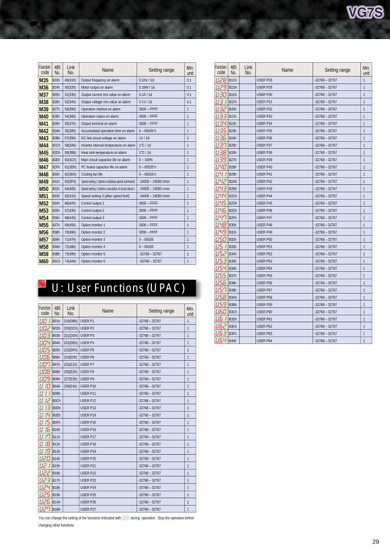
29
M35M36M37M38M39M40M41M42M43M44M45M46M47M48M49M50M51M52M53M54M55M56M57M58M59M60
823h
824h
825h
826h
827h
828h
829h
82Ah
82Bh
82Ch
82Dh
82Eh
82Fh
830h
831h
832h
833h
834h
835h
836h
837h
838h
839h
83Ah
83Bh
83Ch
49(31h)
50(32h)
51(33h)
52(34h)
53(35h)
54(36h)
55(37h)
56(38h)
57(39h)
58(3Ah)
59(3Bh)
60(3Ch)
61(3Dh)
62(3Eh)
63(3Fh)
64(40h)
65(41h)
66(42h)
67(43h)
68(44h)
69(45h)
70(46h)
71(47h)
72(48h)
73(49h)
74(4Ah)
Output frequency on alarm
Motor output on alarm
Output current rms value on alarm
Output voltage rms value on alarm
Operation method on alarm
Operation status on alarm
Output terminal on alarm
Accumulated operation time on alarm
DC link circuit voltage on alarm
Inverter internal temperature on alarm
Heat sink temperature on alarm
Main circuit capacitor life on alarm
PC board capacitor life on alarm
Cooling fan life
Speed setting 1 (before multistep speed command)
Speed setting 2 (before calculation of accel./decel.)
Speed setting 3 (after speed limit)
Control output 1
Control output 2
Control output 3
Option monitor 1
Option monitor 2
Option monitor 3
Option monitor 4
Option monitor 5
Option monitor 6
0.1Hz / 1d
0.1kW / 1d
0.1A / 1d
0.1V / 1d
0000 – FFFF
0000 – FFFF
0000 – FFFF
0 – 65535 h
1V / 1d
1°C / 1d
1°C / 1d
0 – 100%
0 – 65535 h
0 – 65535 h
-24000 – 24000 r/min
-24000 – 24000 r/min
-24000 – 24000 r/min
0000 – FFFF
0000 – FFFF
0000 – FFFF
0000 – FFFF
0000 – FFFF
0 – 65535
0 – 65535
-32768 – 32767
-32768 – 32767
0.1
0.1
0.1
0.1
1
1
1
1
1
1
1
1
1
1
1
1
1
1
1
1
1
1
1
1
1
1
Name Setting rangeLinkNo.
485No.
Function code
Min.unit
Name Setting rangeLinkNo.
485No.
Function code
Min.unit
U: User Functions (UPAC)
Name Setting rangeLinkNo.
485No.
Function code
Min.unit
B1Ch
B1Dh
B1Eh
B1Fh
B20h
B21h
B22h
B23h
B24h
B25h
B26h
B27h
B28h
B29h
B2Ah
B2Bh
B2Ch
B2Dh
B2Eh
B2Fh
B30h
B31h
B32h
B33h
B34h
B35h
B36h
B37h
B38h
B39h
B3Ah
B3Bh
B3Ch
B3Dh
B3Eh
B3Fh
B40h
USER P28
USER P29
USER P30
USER P31
USER P32
USER P33
USER P34
USER P35
USER P36
USER P37
USER P38
USER P39
USER P40
USER P41
USER P42
USER P43
USER P44
USER P45
USER P46
USER P47
USER P48
USER P49
USER P50
USER P51
USER P52
USER P53
USER P54
USER P55
USER P56
USER P57
USER P58
USER P59
USER P60
USER P61
USER P62
USER P63
USER P64
-32768 – 32767
-32768 – 32767
-32768 – 32767
-32768 – 32767
-32768 – 32767
-32768 – 32767
-32768 – 32767
-32768 – 32767
-32768 – 32767
-32768 – 32767
-32768 – 32767
-32768 – 32767
-32768 – 32767
-32768 – 32767
-32768 – 32767
-32768 – 32767
-32768 – 32767
-32768 – 32767
-32768 – 32767
-32768 – 32767
-32768 – 32767
-32768 – 32767
-32768 – 32767
-32768 – 32767
-32768 – 32767
-32768 – 32767
-32768 – 32767
-32768 – 32767
-32768 – 32767
-32768 – 32767
-32768 – 32767
-32768 – 32767
-32768 – 32767
-32768 – 32767
-32768 – 32767
-32768 – 32767
-32768 – 32767
1
1
1
1
1
1
1
1
1
1
1
1
1
1
1
1
1
1
1
1
1
1
1
1
1
1
1
1
1
1
1
1
1
1
1
1
1
You can change the setting of the functions indicated with during operation. Stop the operation before
changing other functions.
B01h
B02h
B03h
B04h
B05h
B06h
B07h
B08h
B09h
B0Ah
B0Bh
B0Ch
B0Dh
B0Eh
B0Fh
B10h
B11h
B12h
B13h
B14h
B15h
B16h
B17h
B18h
B19h
B1Ah
B1Bh
219(DBh)
220(DCh)
221(DDh)
222(DEh)
223(DFh)
224(E0h)
225(E1h)
226(E2h)
227(E3h)
228(E4h)
USER P1
USER P2
USER P3
USER P4
USER P5
USER P6
USER P7
USER P8
USER P9
USER P10
USER P11
USER P12
USER P13
USER P14
USER P15
USER P16
USER P17
USER P18
USER P19
USER P20
USER P21
USER P22
USER P23
USER P24
USER P25
USER P26
USER P27
-32768 – 32767
-32768 – 32767
-32768 – 32767
-32768 – 32767
-32768 – 32767
-32768 – 32767
-32768 – 32767
-32768 – 32767
-32768 – 32767
-32768 – 32767
-32768 – 32767
-32768 – 32767
-32768 – 32767
-32768 – 32767
-32768 – 32767
-32768 – 32767
-32768 – 32767
-32768 – 32767
-32768 – 32767
-32768 – 32767
-32768 – 32767
-32768 – 32767
-32768 – 32767
-32768 – 32767
-32768 – 32767
-32768 – 32767
-32768 – 32767
1
1
1
1
1
1
1
1
1
1
1
1
1
1
1
1
1
1
1
1
1
1
1
1
1
1
1

Options
30
Surge absorber (suppressor)
Arrester
Surge killer
Control option card
Communication option card
Extension cablefor KEYPAD panel
Absorbs surges and noises coming from outside to protect magnetic contactors, mini control relays and timers from malfunction.
Suppresses induced lightning surges from the power source to protect entire equipment connected to the power source.
Absorbs surges and noises coming from outside to protect electronic devices inside the panel from malfunction.
Enables more precise operation, control and installation of different I/Os.
Facilitates system construction including PLCs and PCs.
Used for remote control between an inverter and the KEYPAD panel.
Braking resistor
Braking unit
Powerregenerative PMW converter, RHC series
Dedicated filterfor the RHC series
Increases braking capability for highly frequent stopping and large moment of inertia.
Used in combination with a braking resistor for units of 75kW or more for 200V and 132kW or more for 400V.
Used for suppressing power source harmonics of inverters. It is also equipped with a power supply regenerative function to drastically increase braking capability and reduce energy consumption. Use in combination with dedicated reactors for the RHC series.
Dedicated filter for the RHC series is used if the power supply impedance at the rated current of an inverter exceeds 1% and electronic equipment is connected to the same power supply. Use in combination with dedicated filter reactors, filter capacitors and filter resistors.
EMC compliance filter
Ferrite ring for reducing radio noise
AC reactor (ACR)
DC REACTOR (DCR)
Output circuit filter
Dedicated filter to comply with the European EMC Directive (Emission).
Used to reduce radio noise.Inserting it on the power supply side if the cable length between a motor and an inverter is short (roughly 20m or less) or on the output side if the cable length exceeds 20m is recommended.
Can be used to correct the power-factor and to normalize the power supply. We recommend more efficient, compact and light DC REACTOR. Use only when you require an especially stable power supply such as a DC bus connection (PN connection operation). Use DC REACTOR (DCR) for reducing harmonic.
[For power supply normalization]1Use if the power transformer
capacity is 500kVA or more and exceeds the inverter rated capacity by 10 times.
2Use if the inverter and a thyristor converter are connected with the same transformer.*Check if the thyristor converter uses a commutation reactor. If not, an AC reactor must be connected to the power supply side.
3Connect to prevent trips when trip occurs due to
opening/closing of the phase-advancing capacitor for the power supply lines.
4Use if the voltage unbalance exceeds 2%.
[For improving the input power-factor and reducing harmonics]- Used to reduce the input harmonic
current (correcting power-factor)
Connected to the output of a low-noise inverter to:• Suppress fluctuations of motor
terminal voltage.• Prevent damages to the motor
insulation due to surge voltage in 400V series inverter.
Motor
M
Power supply
L2/SL1/R
L1 L2(R S T)
L3
L1'(U V W)
L2'L3'
X1Y1Z1
X2Y2Z2
L3/T
U V W
P1
P (+)DB
P (+)
N(–)
MCCB or ELCB
(Max. voltage [V] - Min. voltage [V])Voltage
unbalance [%] =Three-phase average voltage [V]× 67[%]
(Conforming to IEC 61800-3 (5.2.3))
MotorM
Power transformer capacity
Main operations/applicationsName Main operations/applicationsName
Option guides
Inve
rter
Inve
rter
Magnetic contactor
DC
RE
AC
TO
R
Com
mut
atio
nre
acto
r
Pow
er-fa
ctor
cor
rect
ing
capa
cito
r
Serie
s con
necte
d re
acto
rT
hyris
tor
conv
erte
r
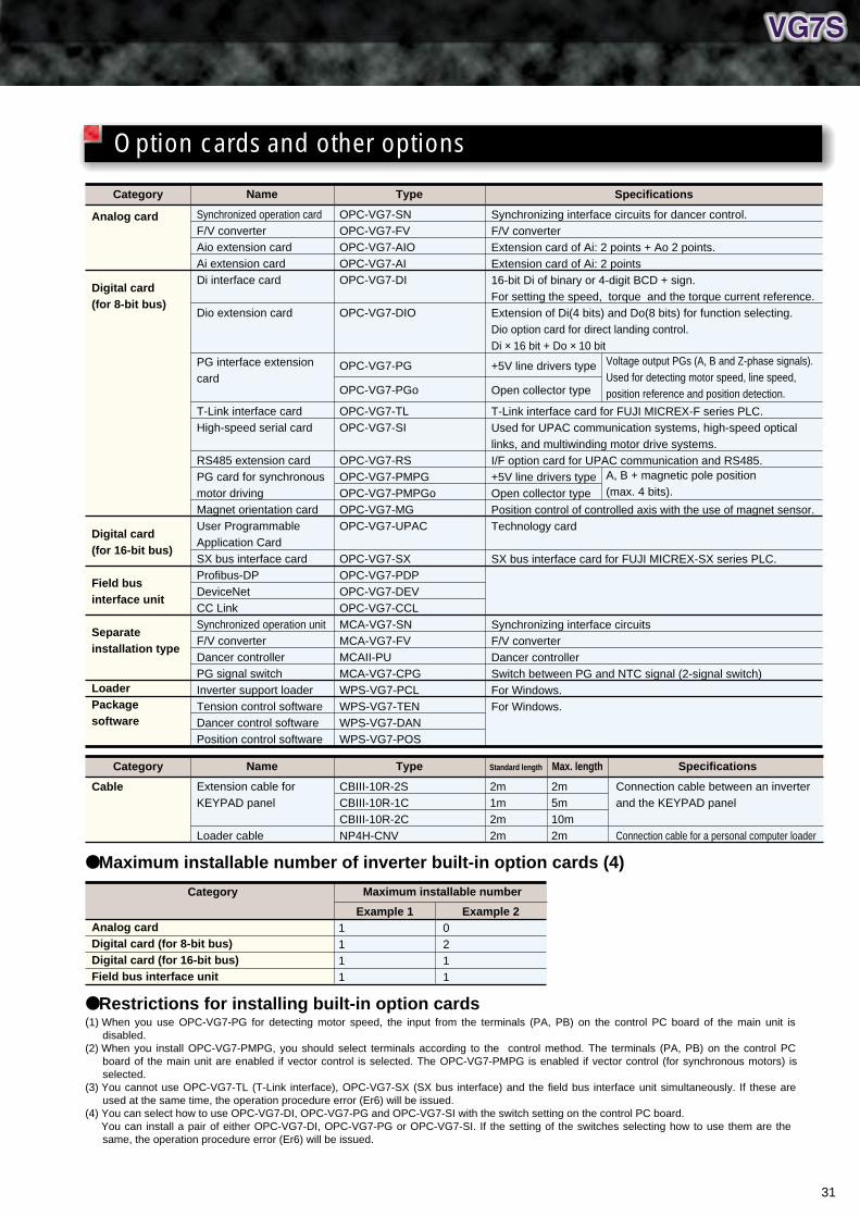
31
Restrictions for installing built-in option cards(1) When you use OPC-VG7-PG for detecting motor speed, the input from the terminals (PA, PB) on the control PC board of the main unit is
disabled.(2) When you install OPC-VG7-PMPG, you should select terminals according to the control method. The terminals (PA, PB) on the control PC
board of the main unit are enabled if vector control is selected. The OPC-VG7-PMPG is enabled if vector control (for synchronous motors) is selected.
(3) You cannot use OPC-VG7-TL (T-Link interface), OPC-VG7-SX (SX bus interface) and the field bus interface unit simultaneously. If these are used at the same time, the operation procedure error (Er6) will be issued.
(4) You can select how to use OPC-VG7-DI, OPC-VG7-PG and OPC-VG7-SI with the switch setting on the control PC board.You can install a pair of either OPC-VG7-DI, OPC-VG7-PG or OPC-VG7-SI. If the setting of the switches selecting how to use them are the same, the operation procedure error (Er6) will be issued.
Maximum installable number of inverter built-in option cards (4)
Category
Analog card
Digital card (for 8-bit bus)
Digital card (for 16-bit bus)
Field bus interface unit
Separate installation type
LoaderPackage software
Name
Synchronized operation cardF/V converterAio extension cardAi extension cardDi interface card
Dio extension card
PG interface extension card
T-Link interface cardHigh-speed serial card
RS485 extension cardPG card for synchronous motor drivingMagnet orientation cardUser ProgrammableApplication CardSX bus interface cardProfibus-DPDeviceNetCC LinkSynchronized operation unitF/V converterDancer controllerPG signal switchInverter support loaderTension control softwareDancer control softwarePosition control software
Type
OPC-VG7-SNOPC-VG7-FVOPC-VG7-AIOOPC-VG7-AIOPC-VG7-DI
OPC-VG7-DIO
OPC-VG7-PG
OPC-VG7-PGo
OPC-VG7-TLOPC-VG7-SI
OPC-VG7-RSOPC-VG7-PMPGOPC-VG7-PMPGoOPC-VG7-MGOPC-VG7-UPAC
OPC-VG7-SXOPC-VG7-PDPOPC-VG7-DEVOPC-VG7-CCLMCA-VG7-SNMCA-VG7-FVMCAII-PUMCA-VG7-CPGWPS-VG7-PCLWPS-VG7-TENWPS-VG7-DANWPS-VG7-POS
Specifications
Synchronizing interface circuits for dancer control.F/V converterExtension card of Ai: 2 points + Ao 2 points.Extension card of Ai: 2 points16-bit Di of binary or 4-digit BCD + sign.For setting the speed, torque and the torque current reference.Extension of Di(4 bits) and Do(8 bits) for function selecting.Dio option card for direct landing control. Di × 16 bit + Do × 10 bit
+5V line drivers type
Open collector type
T-Link interface card for FUJI MICREX-F series PLC.Used for UPAC communication systems, high-speed optical links, and multiwinding motor drive systems.I/F option card for UPAC communication and RS485.+5V line drivers typeOpen collector typePosition control of controlled axis with the use of magnet sensor.Technology card
SX bus interface card for FUJI MICREX-SX series PLC.
Synchronizing interface circuitsF/V converterDancer controllerSwitch between PG and NTC signal (2-signal switch)For Windows.For Windows.
Category
Cable
Name
Extension cable forKEYPAD panel
Loader cable
Type
CBIII-10R-2SCBIII-10R-1CCBIII-10R-2CNP4H-CNV
Standard length
2m1m2m2m
Max. length
2m5m10m2m
Specifications
Connection cable between an inverterand the KEYPAD panel
Connection cable for a personal computer loader
Category
Analog cardDigital card (for 8-bit bus)Digital card (for 16-bit bus)Field bus interface unit
Example 11111
Example 20211
Maximum installable number
Option cards and other options
Voltage output PGs (A, B and Z-phase signals). Used for detecting motor speed, line speed, position reference and position detection.
A, B + magnetic pole position (max. 4 bits).

NOTES:
• Connectors are available for connecting to the inverter. Fuji's RS485/232C converter cable (D-SUB 9 connector) is recommended.
• Though the minimum sampling interval for the real-time trace is 10ms, it may actually be longer due to the communication speed of your personal computer.
• Operation from the KEYPAD panel or the terminal block (external signal input) is disabled in loader trial operations. Operation from the loader is switched to the
personal computer, KEYPAD panel or terminal block automatically for real operations.
• Product technology names related to Windows95, 98 and NT are trademarks or registered trademarks of Microsoft Corporation.
Function list editing Trial operation screen
Real-time trace System monitor
Inverter Support Loader
You can edit, compare and copy the function data. Operation monitoring, real-time/historical traces, fault
monitoring and multiple monitoring are also available. Trial operation and tuning are available. You can monitor the operational status of up to 31
inverters by executing multiple-scan from your personal computer.
You can choose the English or Japanese version on installation.
You can trace 100 points of data sampled at 1ms interval in the historical trace and use them for operation/fault analysis in combination with the trigger function.
Operation is compatible with Windows95, 98 and NT.
Complete Functions
32
Options
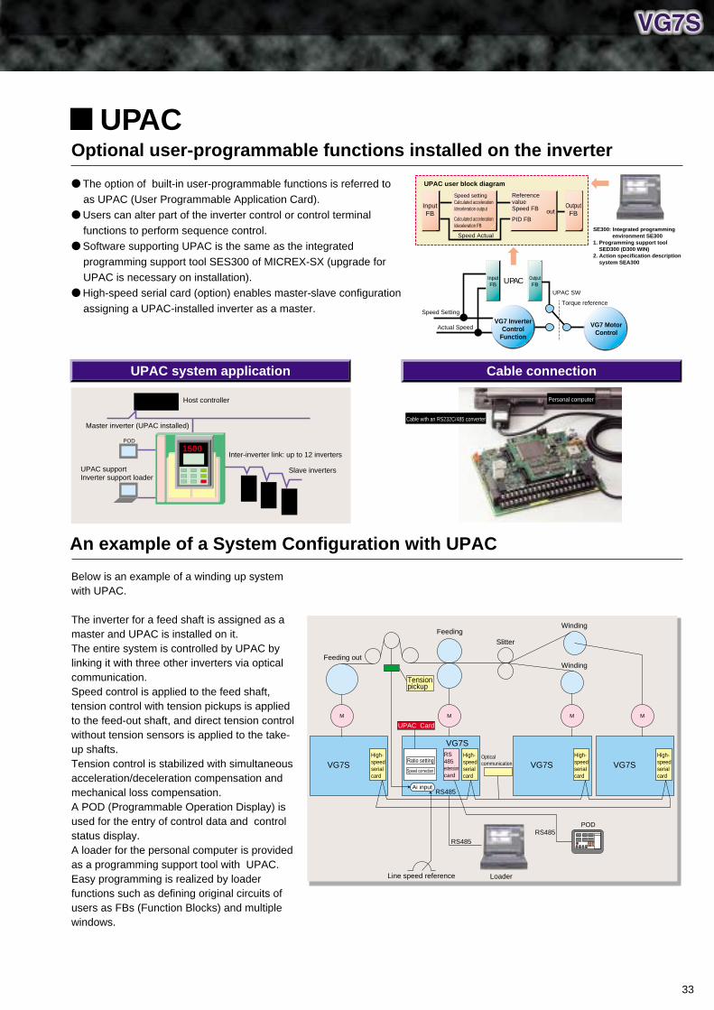
UPAC system application Cable connection
The option of built-in user-programmable functions is referred to as UPAC (User Programmable Application Card).
Users can alter part of the inverter control or control terminal functions to perform sequence control.
Software supporting UPAC is the same as the integrated programming support tool SES300 of MICREX-SX (upgrade for UPAC is necessary on installation).
High-speed serial card (option) enables master-slave configuration assigning a UPAC-installed inverter as a master.
Below is an example of a winding up system with UPAC.
The inverter for a feed shaft is assigned as a master and UPAC is installed on it.The entire system is controlled by UPAC by linking it with three other inverters via optical communication.Speed control is applied to the feed shaft, tension control with tension pickups is applied to the feed-out shaft, and direct tension control without tension sensors is applied to the take-up shafts.Tension control is stabilized with simultaneous acceleration/deceleration compensation and mechanical loss compensation.A POD (Programmable Operation Display) is used for the entry of control data and control status display.A loader for the personal computer is provided as a programming support tool with UPAC. Easy programming is realized by loader functions such as defining original circuits of users as FBs (Function Blocks) and multiple windows.
Optional user-programmable functions installed on the inverter
An example of a System Configuration with UPAC
Personal computer
Cable with an RS232C/485 converter
Host controller
Master inverter (UPAC installed)
Inter-inverter link: up to 12 inverters
Slave inverters
POD
UPAC supportInverter support loader
1500
UPAC
M
High-speed serial card
High-speed serial card
MM
RS485
RS485
PODRS485
Loader
VG7SRS 485 extension card
M
Opticalcommunication
Feeding out
WindingFeeding
Slitter
Winding
UPAC Card
Line speed reference
Tension pickup
Ratio setting
Ai input
Speed correction
UPAC user block diagram
InputFB
Reference valueSpeed FB
PID FB
OutputFB
OutputFB
UPAC SW
Torque reference
Speed Actual
UPAC
Speed Setting
Actual Speed
InputFB
VG7 InverterControl
Function
VG7 MotorControl
out
Speed settingCalculated acceleration/deceleration output
Calculated acceleration/deceleration FB
SE300: Integrated programming environment SE300
1. Programming support tool SED300 (D300 WIN)
2. Action specification description system SEA300
VG7SHigh-speed serial card
VG7SHigh-speed serial card
VG7S
33
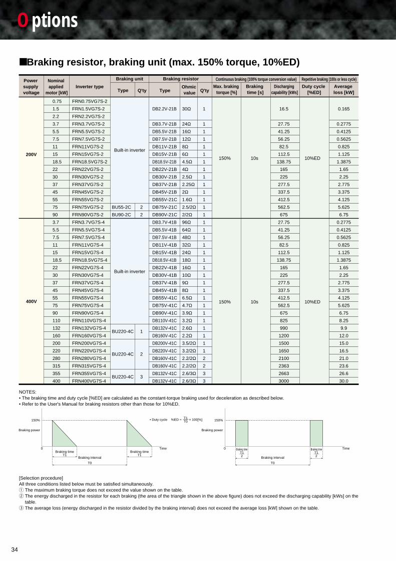
34
Options
NOTES:• The braking time and duty cycle [%ED] are calculated as the constant-torque braking used for deceleration as described below.• Refer to the User's Manual for braking resistors other than those for 10%ED.
[Selection procedure] All three conditions listed below must be satisfied simultaneously.1 The maximum braking torque does not exceed the value shown on the table.2 The energy discharged in the resistor for each braking (the area of the triangle shown in the above figure) does not exceed the discharging capability [kWs] on the
table.3 The average loss (energy discharged in the resistor divided by the braking interval) does not exceed the average loss [kW] shown on the table.
Braking resistor, braking unit (max. 150% torque, 10%ED)
Braking timeT1
0 Time
150%
Braking interval
T0
Braking timeT1
• Duty cycle %ED = × 100[%]T1T0
Braking timeT12
0 Time
150%
Braking interval
T0
Braking timeT12
Power supply voltage
Nominal applied
motor [kW] TypeOhmic value
Average loss [kW]
Duty cycle [%ED]
Discharging capability [kWs]
Braking time [s]
Max. braking torque [%]
Inverter type
Braking unit
Built-in inverter
Built-in inverter
Braking resistor
Type Q'ty Q'ty
Continuous braking (100% torque conversion value) Repetitive braking (100s or less cycle)
200V
400V
FRN0.75VG7S-2
FRN1.5VG7S-2
FRN2.2VG7S-2
FRN3.7VG7S-2
FRN5.5VG7S-2
FRN7.5VG7S-2
FRN11VG7S-2
FRN15VG7S-2
FRN18.5VG7S-2
FRN22VG7S-2
FRN30VG7S-2
FRN37VG7S-2
FRN45VG7S-2
FRN55VG7S-2
FRN75VG7S-2
FRN90VG7S-2
FRN3.7VG7S-4
FRN5.5VG7S-4
FRN7.5VG7S-4
FRN11VG7S-4
FRN15VG7S-4
FRN18.5VG7S-4
FRN22VG7S-4
FRN30VG7S-4
FRN37VG7S-4
FRN45VG7S-4
FRN55VG7S-4
FRN75VG7S-4
FRN90VG7S-4
FRN110VG7S-4
FRN132VG7S-4
FRN160VG7S-4
FRN200VG7S-4
FRN220VG7S-4
FRN280VG7S-4
FRN315VG7S-4
FRN355VG7S-4
FRN400VG7S-4
BU55-2C
BU90-2C
BU220-4C
BU220-4C
BU220-4C
DB2.2V-21B
DB3.7V-21B
DB5.5V-21B
DB7.5V-21B
DB11V-21B
DB15V-21B
DB18.5V-21B
DB22V-21B
DB30V-21B
DB37V-21B
DB45V-21B
DB55V-21C
DB75V-21C
DB90V-21C
DB3.7V-41B
DB5.5V-41B
DB7.5V-41B
DB11V-41B
DB15V-41B
DB18.5V-41B
DB22V-41B
DB30V-41B
DB37V-41B
DB45V-41B
DB55V-41C
DB75V-41C
DB90V-41C
DB110V-41C
DB132V-41C
DB160V-41C
DB200V-41C
DB220V-41C
DB160V-41C
DB160V-41C
DB132V-41C
DB132V-41C
0.75
1.5
2.2
3.7
5.5
7.5
11
15
18.5
22
30
37
45
55
75
90
3.7
5.5
7.5
11
15
18.5
22
30
37
45
55
75
90
110
132
160
200
220
280
315
355
400
2
2
1
2
3
30Ω
24Ω16Ω12Ω8Ω6Ω4.5Ω4Ω2.5Ω2.25Ω2Ω1.6Ω2.5/2Ω2/2Ω96Ω64Ω48Ω32Ω24Ω18Ω16Ω10Ω9Ω8Ω6.5Ω4.7Ω3.9Ω3.2Ω2.6Ω2.2Ω3.5/2Ω3.2/2Ω2.2/2Ω2.2/2Ω2.6/3Ω2.6/3Ω
1
1
1
1
1
1
1
1
1
1
1
1
1
1
1
1
1
1
1
1
1
1
1
1
1
1
1
1
1
1
1
1
2
2
3
3
150%
150%
10s
10s
16.5
27.75
41.25
56.25
82.5
112.5
138.75
165
225
277.5
337.5
412.5
562.5
675
27.75
41.25
56.25
82.5
112.5
138.75
165
225
277.5
337.5
412.5
562.5
675
825
990
1200
1500
1650
2100
2363
2663
3000
10%ED
10%ED
0.165
0.2775
0.4125
0.5625
0.825
1.125
1.3875
1.65
2.25
2.775
3.375
4.125
5.625
6.75
0.2775
0.4125
0.5625
0.825
1.125
1.3875
1.65
2.25
2.775
3.375
4.125
5.625
6.75
8.25
9.9
12.0
15.0
16.5
21.0
23.6
26.6
30.0
Braking power Braking power
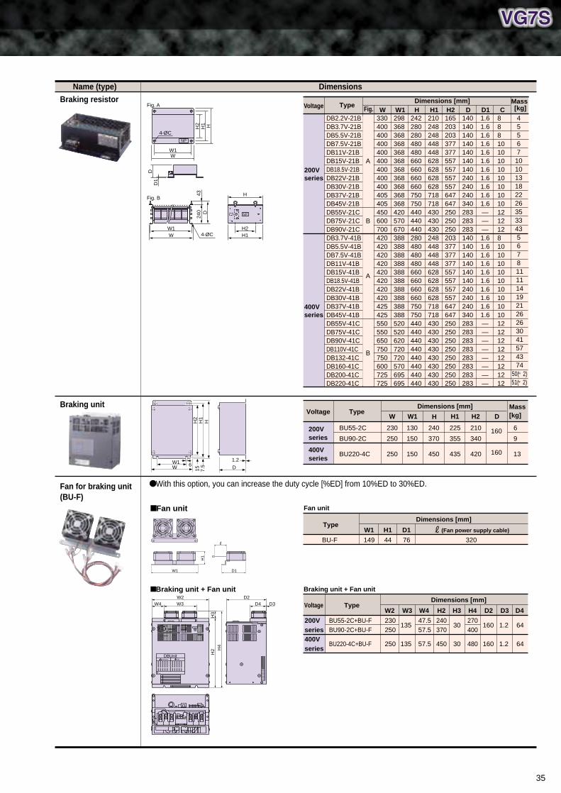
35
H2
H1
H
W 6W1
15 D
1.2
7.5
Voltage TypeDimensions [mm] Mass
[kg]W W1 H H1 H2 D
400V series
200V series
BU55-2C
BU90-2C
BU220-4C
230
250
250
130
150
150
240
370
450
225
355
435
210
340
420
160
160
6
9
13
Name (type)
Braking resistor
Braking unit
Fan for braking unit (BU-F)
With this option, you can increase the duty cycle [%ED] from 10%ED to 30%ED.
Dimensions
TypeDimensions [mm]
WFig. W1 H H1 H2 DDB2.2V-21BDB3.7V-21BDB5.5V-21BDB7.5V-21BDB11V-21BDB15V-21BDB18.5V-21BDB22V-21BDB30V-21BDB37V-21BDB45V-21BDB55V-21CDB75V-21CDB90V-21CDB3.7V-41BDB5.5V-41BDB7.5V-41BDB11V-41BDB15V-41BDB18.5V-41BDB22V-41BDB30V-41BDB37V-41BDB45V-41BDB55V-41CDB75V-41CDB90V-41CDB110V-41CDB132-41CDB160-41CDB200-41CDB220-41C
330400400400400400400400400405405450600700420420420420420420420420425425550550650750750600725725
298368368368368368368368368368368420570670388388388388388388388388388388520520620720720570695695
242280280480480660660660660750750440440440280480480480660660660660750750440440440440440440440440
210248248448448628628628628718718430430430248448448448628628628628718718430430430430430430430430
165203203377377557557557557647647250250250203377377377557557557557647647250250250250250250250250
140140140140140140140240240240340283283283140140140140140140240240240340283283283283283283283283
D11.61.61.61.61.61.61.61.61.61.61.6———1.61.61.61.61.61.61.61.61.61.6————————
CMass [kg]
455671010131822263533435678
11 11 14 19 21 26 26 30 41 57 43 74
50(×2) 51(×2)
888101010101010101012121281010101010101010101212121212121212
Voltage
200V series
400V series
Fan unit
W1
H1
D1
Type
Fan unit
Dimensions [mm]
BU-F 149
W1
44
H1
76
D1
320
(Fan power supply cable)
DBUnitWARNING 危険
Braking unit + Fan unit
H2
H3
H4
W3W4W2
D4 D3D2
TypeDimensions [mm]
BU55-2C+BU-FBU90-2C+BU-F
BU220-4C+BU-F
230250
250
W2
135
135
W3
47.557.5
57.5
W4
240370
450
H2
30
30
H3
270400
480
H4
160
160
D2
1.2
1.2
D4D3
64
64
200V series400V series
Voltage
Braking unit + Fan unit
A
B
A
B
HH1
WW1
DD
1
NP
H2
4-ØC
Fig. A
NP
H
H14-ØC
Fig. B
H2WW1
240
43D
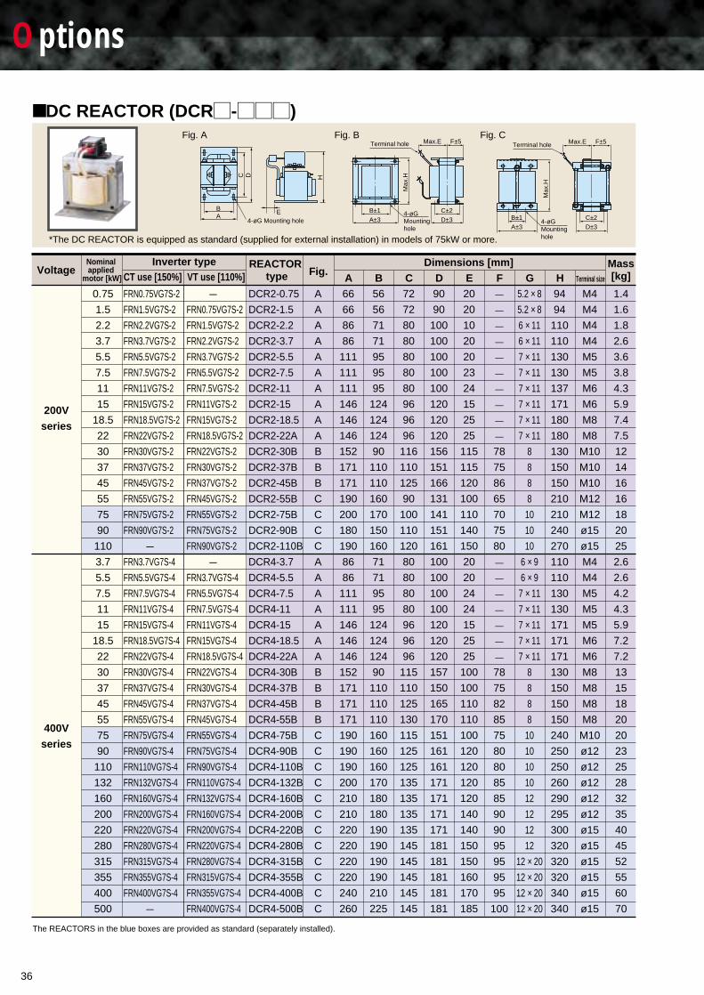
The REACTORS in the blue boxes are provided as standard (separately installed).
DC REACTOR (DCR¤-¤¤¤)
*The DC REACTOR is equipped as standard (supplied for external installation) in models of 75kW or more.
Fig. A Fig. B Fig. C
200Vseries
400Vseries
FRN0.75VG7S-2
FRN1.5VG7S-2
FRN2.2VG7S-2
FRN3.7VG7S-2
FRN5.5VG7S-2
FRN7.5VG7S-2
FRN11VG7S-2
FRN15VG7S-2
FRN18.5VG7S-2
FRN22VG7S-2
FRN30VG7S-2
FRN37VG7S-2
FRN45VG7S-2
FRN55VG7S-2
FRN75VG7S-2
FRN90VG7S-2
—
FRN3.7VG7S-4
FRN5.5VG7S-4
FRN7.5VG7S-4
FRN11VG7S-4
FRN15VG7S-4
FRN18.5VG7S-4
FRN22VG7S-4
FRN30VG7S-4
FRN37VG7S-4
FRN45VG7S-4
FRN55VG7S-4
FRN75VG7S-4
FRN90VG7S-4
FRN110VG7S-4
FRN132VG7S-4
FRN160VG7S-4
FRN200VG7S-4
FRN220VG7S-4
FRN280VG7S-4
FRN315VG7S-4
FRN355VG7S-4
FRN400VG7S-4
—
—
FRN0.75VG7S-2
FRN1.5VG7S-2
FRN2.2VG7S-2
FRN3.7VG7S-2
FRN5.5VG7S-2
FRN7.5VG7S-2
FRN11VG7S-2
FRN15VG7S-2
FRN18.5VG7S-2
FRN22VG7S-2
FRN30VG7S-2
FRN37VG7S-2
FRN45VG7S-2
FRN55VG7S-2
FRN75VG7S-2
FRN90VG7S-2
—
FRN3.7VG7S-4
FRN5.5VG7S-4
FRN7.5VG7S-4
FRN11VG7S-4
FRN15VG7S-4
FRN18.5VG7S-4
FRN22VG7S-4
FRN30VG7S-4
FRN37VG7S-4
FRN45VG7S-4
FRN55VG7S-4
FRN75VG7S-4
FRN90VG7S-4
FRN110VG7S-4
FRN132VG7S-4
FRN160VG7S-4
FRN200VG7S-4
FRN220VG7S-4
FRN280VG7S-4
FRN315VG7S-4
FRN355VG7S-4
FRN400VG7S-4
DCR2-0.75
DCR2-1.5
DCR2-2.2
DCR2-3.7
DCR2-5.5
DCR2-7.5
DCR2-11
DCR2-15
DCR2-18.5
DCR2-22A
DCR2-30B
DCR2-37B
DCR2-45B
DCR2-55B
DCR2-75B
DCR2-90B
DCR2-110B
DCR4-3.7
DCR4-5.5
DCR4-7.5
DCR4-11
DCR4-15
DCR4-18.5
DCR4-22A
DCR4-30B
DCR4-37B
DCR4-45B
DCR4-55B
DCR4-75B
DCR4-90B
DCR4-110B
DCR4-132B
DCR4-160B
DCR4-200B
DCR4-220B
DCR4-280B
DCR4-315B
DCR4-355B
DCR4-400B
DCR4-500B
0.75
1.5
2.2
3.7
5.5
7.5
11
15
18.5
22
30
37
45
55
75
90
110
3.7
5.5
7.5
11
15
18.5
22
30
37
45
55
75
90
110
132
160
200
220
280
315
355
400
500
A
A
A
A
A
A
A
A
A
A
B
B
B
C
C
C
C
A
A
A
A
A
A
A
B
B
B
B
C
C
C
C
C
C
C
C
C
C
C
C
66
66
86
86
111
111
111
146
146
146
152
171
171
190
200
180
190
86
86
111
111
146
146
146
152
171
171
171
190
190
190
200
210
210
220
220
220
220
240
260
56
56
71
71
95
95
95
124
124
124
90
110
110
160
170
150
160
71
71
95
95
124
124
124
90
110
110
110
160
160
160
170
180
180
190
190
190
190
210
225
72
72
80
80
80
80
80
96
96
96
116
110
125
90
100
110
120
80
80
80
80
96
96
96
115
110
125
130
115
125
125
135
135
135
135
145
145
145
145
145
90
90
100
100
100
100
100
120
120
120
156
151
166
131
141
151
161
100
100
100
100
120
120
120
157
150
165
170
151
161
161
171
171
171
171
181
181
181
181
181
20
20
10
20
20
23
24
15
25
25
115
115
120
100
110
140
150
20
20
24
24
15
25
25
100
100
110
110
100
120
120
120
120
140
140
150
150
160
170
185
—
—
——
—
——
—
——
78
75
86
65
70
75
80
—
—
——
—
——
78
75
82
85
75
80
80
85
85
90
90
95
95
95
95
100
5.2 × 85.2 × 86 × 11
6 × 11
7 × 11
7 × 11
7 × 11
7 × 11
7 × 11
7 × 11
8
8
8
8
10
10
10
6 × 96 × 97 × 11
7 × 11
7 × 11
7 × 11
7 × 11
8
8
8
8
10
10
10
10
12
12
12
12
12 × 20
12 × 20
12 × 20
12 × 20
94
94
110
110
130
130
137
171
180
180
130
150
150
210
210
240
270
110
110
130
130
171
171
171
130
150
150
150
240
250
250
260
290
295
300
320
320
320
340
340
M4
M4
M4
M4
M5
M5
M6
M6
M8
M8
M10
M10
M10
M12
M12
ø15
ø15
M4
M4
M5
M5
M5
M6
M6
M8
M8
M8
M8
M10
ø12
ø12
ø12
ø12
ø12
ø15
ø15
ø15
ø15
ø15
ø15
1.4
1.6
1.8
2.6
3.6
3.8
4.3
5.9
7.4
7.5
12
14
16
16
18
20
25
2.6
2.6
4.2
4.3
5.9
7.2
7.2
13
15
18
20
20
23
25
28
32
35
40
45
52
55
60
70
Terminal hole
4-øGMounting hole
B±1
Max
.H
A±3
C±2
Max.E F±5
D±3
Terminal hole
4-øGMounting hole
B±1
Max
.H
A±3
C±2
Max.E F±5
D±3
VoltageNominal applied
motor [kW]
REACTOR type Fig.
Inverter typeCT use [150%] VT use [110%]
Dimensions [mm] Mass[kg]A B C D E F G H Terminal size
E
HC D
BA
4-øG Mounting hole
Options
36
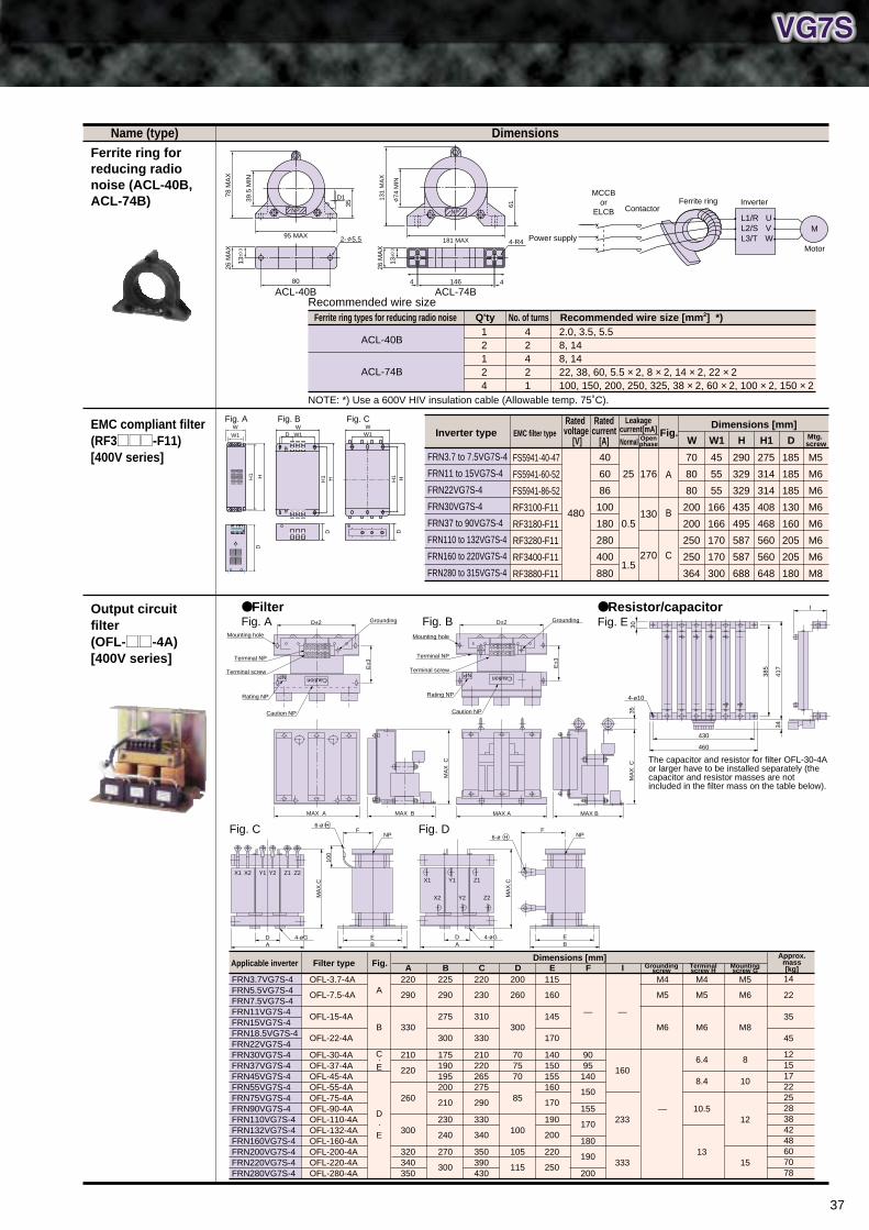
37
Name (type)
Ferrite ring for reducing radio noise (ACL-40B, ACL-74B)
EMC compliant filter (RF3MMM-F11) [400V series]
Output circuit filter (OFL-MM-4A) [400V series]
Dimensions
Recommended wire size
NOTE: *) Use a 600V HIV insulation cable (Allowable temp. 75˚C).
ACL-40B ACL-74B80
26 M
AX
13±0
.32- 5.5
ContactorFerrite ring Inverter
MotorPower supply
L1/RL2/SL3/T
UVW
M
MCCBor
ELCB
1464 4
26 M
AX
13±0
.3
4-R4
HH2
DD1
NP
H1
95 MAX
39.5
MIN
35
78 M
AX
NP
181 MAX
74 M
IN
61
131
MA
X
NP
Ferrite ring types for reducing radio noise Q'ty No. of turns Recommended wire size [mm2] *)
ACL-40B
ACL-74B
12124
42421
2.0, 3.5, 5.58, 148, 1422, 38, 60, 5.5 × 2, 8 × 2, 14 × 2, 22 × 2100, 150, 200, 250, 325, 38 × 2, 60 × 2, 100 × 2, 150 × 2
DW
HH1
D
W1
Fig. BW
HH1
D
W1
Fig. C
FRN3.7VG7S-4FRN5.5VG7S-4FRN7.5VG7S-4FRN11VG7S-4FRN15VG7S-4FRN18.5VG7S-4FRN22VG7S-4FRN30VG7S-4FRN37VG7S-4FRN45VG7S-4FRN55VG7S-4FRN75VG7S-4FRN90VG7S-4FRN110VG7S-4FRN132VG7S-4FRN160VG7S-4FRN200VG7S-4FRN220VG7S-4FRN280VG7S-4
14
22
35
45
121517222528384248607078
Filter type Fig.Dimensions [mm]
A B C D E FOFL-3.7-4A
OFL-7.5-4A
OFL-15-4A
OFL-22-4A
OFL-30-4AOFL-37-4AOFL-45-4AOFL-55-4AOFL-75-4AOFL-90-4AOFL-110-4AOFL-132-4AOFL-160-4AOFL-200-4AOFL-220-4AOFL-280-4A
A
B
C·E
D·E
220
290
330
210
220
260
300
320340350
225
290
275
300
175190195200
210
230
240
270
300
220
230
310
330
210220265275
290
330
340
350390430
200
260
300
707570
85
100
105
115
115
160
145
170
140150155160
170
190
200
220
250
—
9095
140
150
155
170
180
190
200
I
—
160
233
333
Groundingscrew
Terminalscrew H
Mountingscrew G
M4
M5
M6
—
M4
M5
M6
6.4
8.4
10.5
13
M5
M6
M8
8
10
12
15
UVWXYZ
D±2
MAX A MAX B
E±3
MA
X C
Mounting hole
Grounding
Terminal NP
Terminal screw
Rating NP
Caution NP
CautionNP
UVWXYZ
D±2
MAX A MAX B
E±3
MA
X C
35Mounting hole
Grounding
Terminal NP
Terminal screw
Rating NP
Caution NP
CautionNP
D
6-ø H
NP
EB
F
MA
X.C
100
4-øG
Z1 Z2Y1 Y2X1 X2
AD
6-ø H NP
EB
F
MA
X.C
4-øG
Z1
Z2
Y1
Y2
X1
X2
A
FilterFig. A Fig. B
Fig. C Fig. D
4-ø10
430
460
I
385
417
34
30
Resistor/capacitorFig. E
Applicable inverterApprox.
mass[kg]
The capacitor and resistor for filter OFL-30-4A or larger have to be installed separately (the capacitor and resistor masses are not included in the filter mass on the table below).
Inverter type EMC filter type Fig.Dimensions [mm]
WNormal Openphase W1 H H1
FS5941-40-47
FS5941-60-52
FS5941-86-52
RF3100-F11
RF3180-F11
RF3280-F11
RF3400-F11
RF3880-F11
480
40
60
86
100
180
280
400
880
25
0.5
1.5
176
130
270
A
B
C
FRN3.7 to 7.5VG7S-4
FRN11 to 15VG7S-4
FRN22VG7S-4
FRN30VG7S-4
FRN37 to 90VG7S-4
FRN110 to 132VG7S-4
FRN160 to 220VG7S-4
FRN280 to 315VG7S-4
70
80
80
200
200
250
250
364
45
55
55
166
166
170
170
300
290
329
329
435
495
587
587
688
275
314
314
408
468
560
560
648
D
185
185
185
130
160
205
205
180
Mtg. screw
M5
M6
M6
M6
M6
M6
M6
M8
Rated voltage
[V]
Ratedcurrent
[A]
Leakagecurrent[mA]
Fig. A
H
W1
W
H1
D
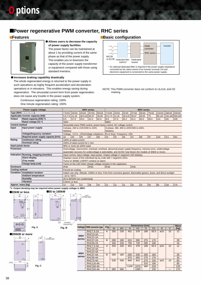
38
Options
Power regenerative PWM converter, RHC seriesFeatures
Allows users to decrease the capacityof power supply facilitiesThe power-factor can be maintained atabout 1 by providing current of the samephase as that of the power supply.This enables you to downsize thecapacity of the power supply transformeror equipment compared with those usingstandard inverters.
Increases braking capability drasticallyThe whole regenerated energy is returned to the power supply insuch operations as highly frequent acceleration and decelerationoperations or in elevators. This enables energy saving duringregeneration. The sinusoidal current form from power regenerationdoes not cause any trouble in the power supply system.
Continuous regeneration rating: 100%One minute regeneration rating: 150%
Dedicated filter (option)*
Dedicated reactor
PWM converter
RHC series
MCCB or ELCB
Inverter
* An optional dedicated filter is required if the power supply impedance converted by the rated current of an inverter exceeds 1% and electronic equipment is connected to the same power supply.
7.5•2A5.5,7.58.5340VSinusoidal wave PWM control, power-factor control, DC voltage control.3-phase, 200 to 210V/200 to 220V,50/60HzVoltage: +10 to –15%(Voltage unbalance: 3% or less) Frequency: ±5%10100% of rated current150% of rated current for 1 min.95% or more (at 100% load)Overvoltage, overcurrent, overload, overheat, abnormal power supply frequency, memory error, undervoltage (automatic recovery for undervoltage is selectable), and AC/DC fuse blown (for models of 30kW or more).Input current, Input voltage, Input power, Output voltage (7-segment LED display)Displays cause of the individual trip by code with 7-segment LEDs.Turns on 30ABC (1SPDT contact) on alarm.Turns on the LED when charge voltage remains in the capacitors.IP40Forced air coolingIndoor use only. Altitude: 1000m or less. Free from corrosive gasses, flammable gasses, dusts, and direct sunlight. –10 to +50˚C20 to 90%RH (no condensing)5.9m/s2 or less12
15•2A11,1517.0
20
12
22•2A18.5,2225.2
29
12
55•2A45,5562.0
69
44
7.5•4A5.5,7.58.8680V
3-phase, 380, 400 to 420V/400 to 440V, 50/60Hz
10
IP40
12
15•4A11,1517.0
20
12
22•4A18.5,2225.2
29
12
37•4A30,3741.0
47
IP00
26
55•4A45,5562.0
69
33
110•4A90,110124
144
85
160•4A132,160181
211
120
220•4A200,220249
291
175
75•4A7583.0
97
60
37•2A30,3741.0
47
IP00
28
Rated capacity [kW] *1Rated voltage [V] *1
Input power supply
Voltage/frequency variationRequired power supply capacity [kVA]Continuous ratingOverload rating
Running, stopping (monitor)Alarm display(Trip mode)Charge lamp (red)
Installation locationAmbient temperatureHumidityVibration
*1: Output derating may be required when power supply voltage is 380V.
Power supply voltage 200V series 400V seriesType (RHC MMM-MM)Applicable inverter capacity [kW]Output
Control methodInput
Rating
Input power-factorProtection
Indication
EnclosureCooling methodCondition
Approx. mass [kg]
Valtage PWM converter type Fig.Dimensions [mm] Mass
[kg]W W1 H H1 D D1
200Vseries
400Vseries
RHC7.5-2ARHC15-2ARHC22-2ARHC37-2ARHC55-2ARHC7.5-4ARHC15-4ARHC22-4ARHC37-4ARHC55-4ARHC75-4ARHC110-4ARHC160-4ARHC220-4A
A
B
A
B
C
255
280340255
280
530
680
226
180240226
180
430
580
401
615750401
550675840
1100
378
595730378
530655810
10701080
189
275280189
265275270315360
93.5
17016593.5
160170150190220245
Bø10
ø10
ø15
C10
10
15
—
12
284412
26336085
120175
22kW or less
Fig. A
PWMCONVERTER
NP
NP
W
HH1
W1D
D1B
C
30 to 160kW
Fig. B
N P
PWMCONVERTER
W1 D1 2-ø15LIFTING HOLE
W DB
H1 H
C EXTERNALCOOLING USE
Fig. C
200kW or moreW
B ø23D
D1
H1
3511
0H
W1
610
TB2
TB1TB1
4-ø15
LIFTING HOLE
CONVERTERPWM
N P
TB2
Basic configuration
NOTE: This PWM converter does not conform to UL/cUL and CEmarking.
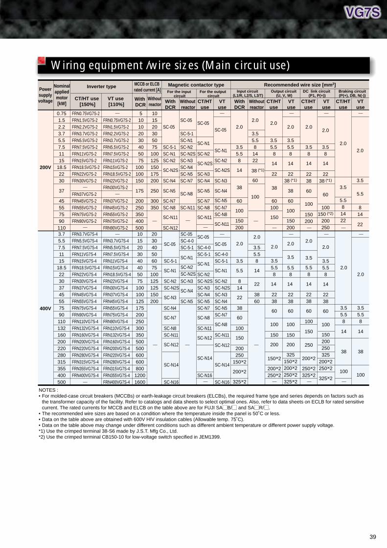
39
5 10 10 20 30 40 50 75100100150
175
200250350400500
0.751.52.23.75.57.51115
18.52230
37
45557590110
SC-05
SC-5-1SC-N1SC-N2
SC-N2S
SC-N4
SC-N5
SC-N7SC-N8
SC-N11
SC-N12
SC-05
SC-N1
SC-N2
SC-N2S
SC-N3SC-N4
SC-N5
SC-N7SC-N8
SC-N11
SC-05
SC-N1
SC-N2
SC-N2S
SC-N3
SC-N4
SC-N5
SC-N7SC-N8
SC-N11
2.0
3.55.58
14
38
60
100
150200
2.0
3.5 5.5 8
14
22
38
60100
150
2.0
3.58
14
2238
60
100
150200
2.0
3.58
14
2238 (*1)
60
100150 (*2)
200250
2.0
3.5
5.581422
2.0
3.5
5.5
814
22
2.0
3.55.58
1422
38 (*1)
60
100
SC-05
SC-5-1SC-N1SC-N2SC-N2SSC-N3SC-N4SC-N5SC-N7
SC-N8
SC-N11
101520305075100125150175200
250
300350
2.0
3.55.58
14
2238 (*1)
38
60
100
150200
FRN0.75VG7S-2FRN1.5VG7S-2FRN2.2VG7S-2FRN3.7VG7S-2FRN5.5VG7S-2FRN7.5VG7S-2FRN11VG7S-2FRN15VG7S-2FRN18.5VG7S-2FRN22VG7S-2FRN30VG7S-2
FRN37VG7S-2FRN45VG7S-2FRN55VG7S-2FRN75VG7S-2FRN90VG7S-2
FRN0.75VG7S-2FRN1.5VG7S-2FRN2.2VG7S-2FRN3.7VG7S-2FRN5.5VG7S-2FRN7.5VG7S-2FRN11VG7S-2FRN15VG7S-2FRN18.5VG7S-2FRN22VG7S-2FRN30VG7S-2
FRN37VG7S-2FRN45VG7S-2FRN55VG7S-2FRN75VG7S-2FRN90VG7S-2
200V
101520304040507510010012517520025030035050050060060080012001600
3.75.57.51115
18.522303745557590110132160200220280315355400500
SC-05
SC-5-1
SC-N1
SC-N2SC-N2S
SC-N3
SC-N4
SC-N7
SC-N8SC-N11
SC-N12
SC-N14
SC-N16
SC-05
SC-4-0SC-5-1
SC-N1
SC-N2SC-N2SSC-N3SC-N4SC-N5SC-N7
SC-N8
SC-N11
SC-N12
SC-N14
SC-N16
SC-05
SC-4-0SC-5-1
SC-N1
SC-N2SC-N2SSC-N3SC-N4SC-N5SC-N7
SC-N8
SC-N11
SC-N12
SC-N14
SC-N16
2.0
3.5
5.5
814
22
38
60
100
150
200250
150×2
200×2
325×2
2.0
3.55.58
14
2238
60
100
150
200
150×2
200×2250×2
2.0
3.5
5.58
14
2238
60
100
150
250
200×2
250×2325×2
2.0
3.55.58
14
22
3860
SC-05SC-4-0SC-5-1
SC-N1
SC-N2SC-N2S
SC-N3
SC-N4
SC-N5
203040506075100125125150200
2.0
3.5
5.58
14
2238
60
100
150
200
325150×2200×2250×2325×2
2.0
3.55.58
14
2238
60
100
150200250325
200×2250×2
325×2
2.0
3.55.58
14
38
100
2.0
3.55.58
14
38
100
FRN3.7VG7S-4FRN5.5VG7S-4FRN7.5VG7S-4FRN11VG7S-4FRN15VG7S-4FRN18.5VG7S-4FRN22VG7S-4FRN30VG7S-4FRN37VG7S-4FRN45VG7S-4FRN55VG7S-4FRN75VG7S-4FRN90VG7S-4FRN110VG7S-4FRN132VG7S-4FRN160VG7S-4FRN200VG7S-4FRN220VG7S-4FRN280VG7S-4FRN315VG7S-4FRN355VG7S-4FRN400VG7S-4
FRN3.7VG7S-4FRN5.5VG7S-4FRN7.5VG7S-4FRN11VG7S-4FRN15VG7S-4FRN18.5VG7S-4FRN22VG7S-4FRN30VG7S-4FRN37VG7S-4FRN45VG7S-4FRN55VG7S-4FRN75VG7S-4FRN90VG7S-4FRN110VG7S-4FRN132VG7S-4FRN160VG7S-4FRN200VG7S-4FRN220VG7S-4FRN280VG7S-4FRN315VG7S-4FRN355VG7S-4FRN400VG7S-4
400V
Inverter type Magnetic contactor type Recommended wire size [mm2]Input circuit
(L1/R, L2/S, L3/T)For the input
circuitCT/HT use
[150%]VT use [110%]
With DCR
Without reactor
WithDCR
Without reactor
CT/HTuse
Withoutreactor
For the output circuit
MCCB or ELCB rated current [A]
WithDCR
Output circuit (U, V, W)
DC link circuit (P1, P(+))
Braking circuit(P(+), DB, N(-))
CT/HTuse
VTuse
VTuse
VTuse
VTuse
CT/HTuse
CT/HTuse
Powersupplyvoltage
Nominalappliedmotor[kW]
NOTES :• For molded-case circuit breakers (MCCBs) or earth-leakage circuit breakers (ELCBs), the required frame type and series depends on factors such as
the transformer capacity of the facility. Refer to catalogs and data sheets to select optimal ones. Also, refer to data sheets on ECLB for rated sensitivecurrent. The rated currents for MCCB and ELCB on the table above are for FUJI SAMB/M and SAMR/M.
• The recommended wire sizes are based on a condition where the temperature inside the panel is 50˚C or less.• Data on the table above are obtained with 600V HIV insulation cables (Allowable temp. 75˚C).• Data on the table above may change under different conditions such as different ambient temperature or different power supply voltage.*1) Use the crimped terminal 38-S6 made by J.S.T. Mfg Co., Ltd.*2) Use the crimped terminal CB150-10 for low-voltage switch specified in JEM1399.
Wiring equipment /wire sizes (Main circuit use)

Application to general-purpose motors
• Driving a 400V general-purpose motorWhen driving a general-purpose motor of 400Vseries by an inverter, the motor insulation may bedamaged. Consult the motor maker and, ifnecessary, use the output circuit filter (OFL). Thefilter, however, is not necessary when you order aFuji's motor because it has enhanced insulationresistance.
• Torque characteristics and temperature riseWhen the inverter is used to operate a general-purpose motor, the temperature rises a littlehigher than during operation by a commercialpower supply. The cooling effect decreases in thelow-speed range, reducing the allowable outputtorque. (If a constant torque is required in the low-speed range, use a Fuji inverter motor or a motorequipped with a separately ventilating fan.)
• VibrationUse of an inverter does not increase vibration of ageneral-purpose motor, but when the motor ismounted to a machine, resonance may becaused by the natural frequencies including thenatural frequency of the machine system.* We recommend that you use rubber coupling oranti-vibration rubber.* We also recommend that you use the inverterjump frequency control function to avoidresonance point in the motor operation.Note that operation of a 2-pole motor at 60Hz orover may cause abnormal vibration.
• NoiseWhen an inverter drives a general-purpose motor,the motor noise level increases compared withbeing driven by a commercial power supply.To reduce noise, set the inverter carrier frequencyat a high level.High-speed operation at 60Hz or over can resultin more noise.
Application to special motors
• Explosion-proof motorsWhen driving an explosion-proof motor with aninverter, use a combination of a motor and aninverter that has been approved in advance. Suchapproved products are available in our specialproduct series. Contact Fuji for details.
• Submersible motors and pumpsThese motors have a larger rated current thangeneral-purpose motors. Select the invertercapacity so that these motors can run within theinverter rated current.These motors differ from general-purpose motorsin thermal characteristics. Set a small valueaccording to the motor’s thermal time constant forsetting electronic thermal relay function.
• Brake motorsFor motors with parallel-connection brakes, obtainthe brake power from the primary circuit(commercial power supply). If you connect thebrake power to the inverter power output circuitby mistake, problems may occur.Do not use inverters for driving motors equippedwith series-connection brakes.
• Geared motorsWhen the power transmission mechanism usesan oil-lubricated gearbox or speed changer/reducer, continuous motor operation at low speedmay cause poor lubrication.
• Synchronous motorsSynchronous motors can be driven by Fuji VG7Sinverter (optional card required).Contact Fuji for details.
• Single-phase motorsSingle-phase motors are not suitable for inverter-driven variable speed operation. Use a three-phase motor.* Even if a single-phase power supply isavailable, use a three-phase motor, because theinverter provides three-phase output.
Combination with peripheral device
• Installation locationUse the inverter in an ambient temperature rangebetween -10˚ and 50˚C.Install an inverter on non-flammable materialbecause the inverter and braking resistorsurfaces become hot under certain operatingconditions. Also ensure that the inverterinstallation place satisfies the environmentalconditions specified for the inverter.
• Installing Auto Breaker (MCCB)Install Fuji Auto Breaker (MCCB) or earth-leakage circuit breaker in the primary circuit ofthe inverter to protect wires.
• Magnetic contactor in the secondary circuitIf a magnetic contactor is mounted in thesecondary circuit for switching to the motoroperation by commercial power supply or for anyother purposes, ensure that the inverter and themotor are stopped before you turn on or off thecontactor.
• Magnetic contactor in the primary circuitDo not open or close the magnetic contactor inthe primary circuit more than once an hour.If frequent starts and stops are required duringmotor operation, send FWD and REV signals toand from the control terminal.
• Protecting the motorWhen you drive a motor with an inverter, themotor can be protected with an electronic thermalrelay function of the inverter.
In addition to the operation level, set the motortype (general-purpose motor, inverter motor). Forhigh-speed motors or water-cooled motors, set asmall value as the thermal time constant andprotect the motor in combination with the coolingsystem OFF signal.
When driving several motors with an inverter,connect a thermal overload relay to each motorand turn on the inverter’s electronic thermal relay.
If you connect the motor thermal relay to themotor with a long cable, high-frequency currentmay flow into the wiring floating capacity. Thismay cause the relay to trip at a current lower thanthe set value for the thermal relay. If thishappens, lower the carrier frequency or use theoutput circuit filter (OFL).
• Power-factor correcting capacitorDo not mount the power-factor correctingcapacitor in the inverter primary circuit. (Use theDC REACTOR to improve the inverter power-factor.)Do not use the power-factor correcting capacitorin the inverter secondary circuit. Overcurrent tripwill occur, disabling motor operation.
• Reducing noiseUse of filter and shielded wires are typicalmeasures against noise that meets EMCDirectives. For details, refer to the operationprocedure manual.
• Measures against surge currentIf OV trip occurs while the inverter is stopped oroperated under a light load, it is assumed that thesurge current is generated by open/close of thephase-advancing capacitor in the power system.* Connect a DC REACTOR to the inverter.
• Megger testWhen checking insulation resistance of theinverter, use a 500V megger and follow theinstructions described in the instruction manual.
Wiring
• Control circuit wiring lengthWhen conducting a remote control, limit thewiring length between the inverter and theoperator box to 20m or less and use twistedshield cable.
• Wiring length between inverter and motorIf long wiring is used between the inverter andthe motor, the inverter will overheat or tripbecause of overcurrent (under the influence ofhigh-frequency current flowing into the floatingcapacity) in the wires connected to the phases.Ensure that the wiring is shorter than 50m.If 50m must be exceeded, lower the carrierfrequency or mount an output circuit filter (OFL).When wiring is longer than 50m, and Dynamictorque-vector control or vector with PG isselected, execute off-line tuning.
• Wiring sizeSelect a cable with a sufficient capacity byreferring to the current value or recommendedwire size.
• GroundingSecurely ground the inverter using the groundingterminal.
Selecting inverter capacity
• Driving general-purpose motorSelect an inverter from the capacity range ofnominal applied motors shown on the inverterstandard specifications table. When large startingtorque is required or acceleration or decelerationis required in a short time, select an inverter witha capacity one class greater than the standard.
• Driving special motorSelect an inverter that meets the followingcondition:Inverter rated current > Motor rated current
Transportation, storage inverters
When transporting or storing inverters, select theprocedures and places that meet the environ-mental conditions given in the inverterspecifications.Ensure the above environmental conditions aremet also when transporting an inverter mountedto a machine.
Fuji Electric Co., Ltd.ED & C · Drive Systems CompanyGate City Ohsaki, East Tower, 11-2, Osaki 1-chomeShinagawa-ku, Tokyo 141-0032, JapanPhone: +81-3-5435-7139 Fax: +81-3-5435-7460
Information in this catalog is subject to change without notice. Printed in Japan 2001-9(I01a/B00)CM 30 FIS
Printed on 100% recycled paper
NOTES