
he ext eneratiOn reight levatOr OOrs - Courion Doors...
24
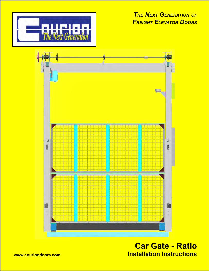
THE NEXT GENERATION OF FREIGHT ELEVATOR DOORS Car Gate - Ratio Installation Instructions www.couriondoors.com
Transcript of he ext eneratiOn reight levatOr OOrs - Courion Doors...
Opening Quality DOOrs arOunD the WOrlD
the next generatiOn Offreight elevatOr DOOrs
Car Gate - Ratio Installation Instructionswww.couriondoors.com

For Immediate Help Call 1-800-533-5760
2Opening Quality DOOrs arOunD the WOrlD Ver 052012
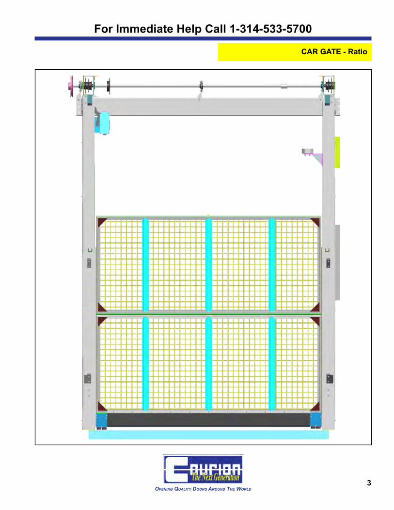
CAR GATE - Ratio
TABLE OF CONTENTSCheck Car Enclosure Set Back ..................................................................................... 4Step q: Car Gate Guides .............................................................................................. 7Step w: Gate Drive Assembly ........................................................................................ 8Step e: Counterweight Sprocket Cluster ....................................................................... 10Step r: Car Gate Panels ............................................................................................... 11Step t: Gate Chains ..................................................................................................... 13Step y: Gate Drive Chain .............................................................................................. 14Step u: Gate Contact .................................................................................................... 15Step i: Gate Geared Limit Switch or Gate iSENOR.g .................................................. 16Step o: Gate Motor ....................................................................................................... 18Step a: Knee and Angle Braces .................................................................................... 19Step s: Web Straps ....................................................................................................... 20Step 1@: Reversing Edge and Swivel Reel Assembly ..................................................... 20Adjust Geared Limit Switch ............................................................................................ 21Gate iDRIVE VFD Control ............................................................................................. 22CARE Light Curtain ....................................................................................................... 22
THE INFORMATION CONTAINED IN THIS DOCUMENT IS THE EXCLUSIVE PROPERTY OF COMPREHENSIVE MANUFACTURING
SERVICES, LLC. d/b/a COURION. ANY REPRODUCTION OR DISSEMINATION OF THE CONTENTS, DESIGNS OR IDEAS
CONTAINED HEREIN IS HEREBY PROHIBITED.
© COURION 2012
For Immediate Help Call 1-314-533-5700
3Opening Quality DOOrs arOunD the WOrlD
CAR GATE - Ratio

For Immediate Help Call 1-800-533-5760
4Opening Quality DOOrs arOunD the WOrlD Ver 052012
CAR GATE - Ratio
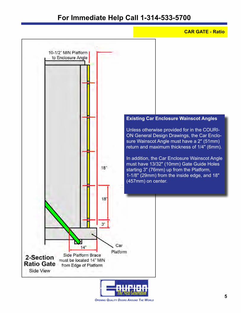
Check Car Enclosure Set Back - Using the Approved General Design Drawings pro-vided by COURION, insure that the Car Enclosure has the following MINIMUM Set Backs from the edge of the Platform:
• Wainscot Angles and Canopy 10-1/2" (267mm)• Car Operating Panel 16-1/2" (420mm)• Car Brace Rod 14" (360mm)
If your actual CAR SET BACK does not meet these minimum requirements, stop and call Courion immediately at (800) 533-5760 or (314) 533-5700.
For Immediate Help Call 1-314-533-5700
5Opening Quality DOOrs arOunD the WOrlD
CAR GATE - Ratio
Existing Car Enclosure Wainscot Angles
Unless otherwise provided for in the COURI-ON General Design Drawings, the Car Enclo-sure Wainscot Angle must have a 2" (51mm) return and maximum thickness of 1/4" (6mm).
In addition, the Car Enclosure Wainscot Angle must have 13/32" (10mm) Gate Guide Holes starting 3" (76mm) up from the Platform, 1-1/8" (29mm) from the inside edge, and 18" (457mm) on center.
For Immediate Help Call 1-800-533-5760
6Opening Quality DOOrs arOunD the WOrlD Ver 052012
CAR GATE - Ratio
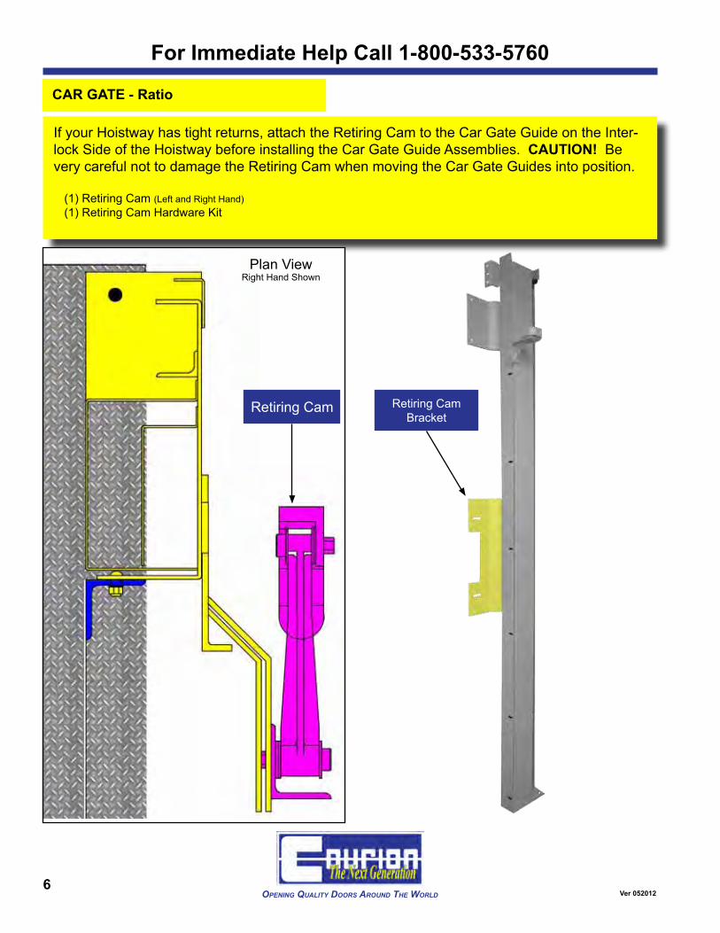
Retiring Cam Bracket
If your Hoistway has tight returns, attach the Retiring Cam to the Car Gate Guide on the Inter-lock Side of the Hoistway before installing the Car Gate Guide Assemblies. CAUTION! Be very careful not to damage the Retiring Cam when moving the Car Gate Guides into position.
(1) Retiring Cam (Left and Right Hand)(1) Retiring Cam Hardware Kit
Retiring Cam
Plan ViewRight Hand Shown

For Immediate Help Call 1-314-533-5700
7Opening Quality DOOrs arOunD the WOrlD
CAR GATE - Ratio
q With the WEIGHT BOX COVERS removed from the Car Gate Guides, attach the CAR GATE GUIDES to the Car Enclosure Wainscot Angles using the fasteners found in Hardware Kit #94-000500. Hand Tighten Only.
(1 pr) Gate Guides (Left and Right Hand)
(1) Gate Guide Hardware Kit #500 (Part #94-000500)
Hand Tighten the fasteners found in Hardware Kit #500 at
this time
Remove the Weight Box Covers before
installing Gate Guides

For Immediate Help Call 1-800-533-5760
8Opening Quality DOOrs arOunD the WOrlD Ver 052012
CAR GATE - Ratio
w Attach the DRIVE BEAM to the Drive Beam Brackets on the Gate Guides using the fas-teners found in Hardware Kit # 94-000501.
(1) Drive Beam (Length varies by Job)
(1) Drive Beam Hardware Kit #501 (Part #94-000501)
Drive Beam Brackets
Hand tighten the fasteners found in Hardware Kit #501
at this time.Plan ViewRight Hand Shown
For Immediate Help Call 1-314-533-5700
9Opening Quality DOOrs arOunD the WOrlD
CAR GATE - Ratio
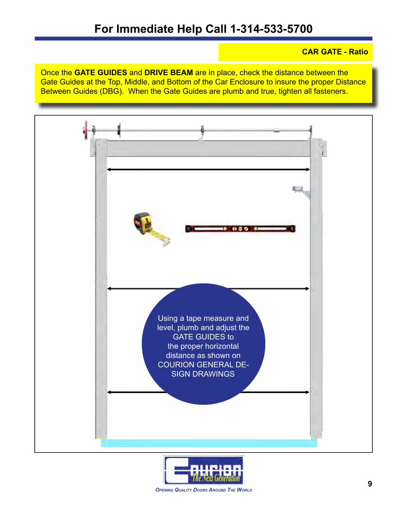
Once the GATE GUIDES and DRIVE BEAM are in place, check the distance between the Gate Guides at the Top, Middle, and Bottom of the Car Enclosure to insure the proper Distance Between Guides (DBG). When the Gate Guides are plumb and true, tighten all fasteners.
Using a tape measure and level, plumb and adjust the
GATE GUIDES to the proper horizontal distance as shown on
COURION GENERAL DE-SIGN DRAWINGS

For Immediate Help Call 1-800-533-5760
10Opening Quality DOOrs arOunD the WOrlD Ver 052012
CAR GATE - Ratio
e Mount the COUNTERWEIGHT SPROCKETS to the top of each Gate Guide using fasten-ers found in Hardware Kit # 94-000502.
(2) Counterweight Sprockets (1) Counterweight Sprocket Hardware Kit #502 (#94-000502)
For Immediate Help Call 1-314-533-5700
11Opening Quality DOOrs arOunD the WOrlD
CAR GATE - Ratio
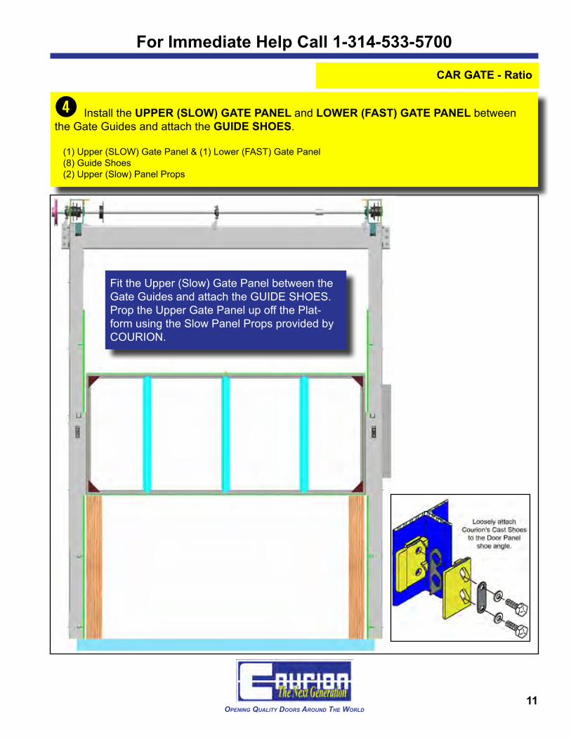
r Install the UPPER (SLOW) GATE PANEL and LOWER (FAST) GATE PANEL between the Gate Guides and attach the GUIDE SHOES.
(1) Upper (SLOW) Gate Panel & (1) Lower (FAST) Gate Panel (8) Guide Shoes(2) Upper (Slow) Panel Props
Fit the Upper (Slow) Gate Panel between the Gate Guides and attach the GUIDE SHOES. Prop the Upper Gate Panel up off the Plat-form using the Slow Panel Props provided by COURION.

For Immediate Help Call 1-800-533-5760
12Opening Quality DOOrs arOunD the WOrlD Ver 052012
CAR GATE - Ratio
Fit the Lower (Fast) Gate Panel between the Gate Guides and attach the GUIDE SHOES. Let the Lower (Fast) Gate Panel rest on the Car Platform.
For Immediate Help Call 1-314-533-5700
13Opening Quality DOOrs arOunD the WOrlD
CAR GATE - Ratio
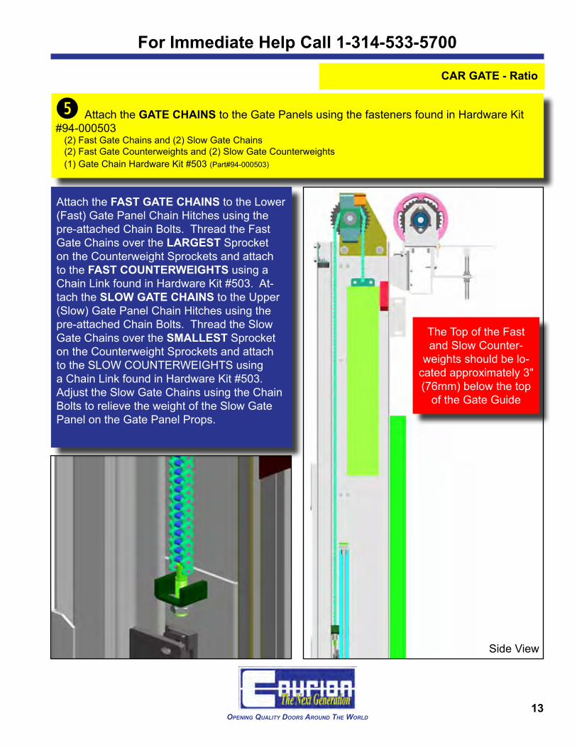
t Attach the GATE CHAINS to the Gate Panels using the fasteners found in Hardware Kit #94-000503
(2) Fast Gate Chains and (2) Slow Gate Chains(2) Fast Gate Counterweights and (2) Slow Gate Counterweights(1) Gate Chain Hardware Kit #503 (Part#94-000503)
The Top of the Fast and Slow Counter-
weights should be lo-cated approximately 3" (76mm) below the top
of the Gate Guide
Attach the FAST GATE CHAINS to the Lower (Fast) Gate Panel Chain Hitches using the pre-attached Chain Bolts. Thread the Fast Gate Chains over the LARGEST Sprocket on the Counterweight Sprockets and attach to the FAST COUNTERWEIGHTS using a Chain Link found in Hardware Kit #503. At-tach the SLOW GATE CHAINS to the Upper (Slow) Gate Panel Chain Hitches using the pre-attached Chain Bolts. Thread the Slow Gate Chains over the SMALLEST Sprocket on the Counterweight Sprockets and attach to the SLOW COUNTERWEIGHTS using a Chain Link found in Hardware Kit #503. Adjust the Slow Gate Chains using the Chain Bolts to relieve the weight of the Slow Gate Panel on the Gate Panel Props.
Side View

For Immediate Help Call 1-800-533-5760
14Opening Quality DOOrs arOunD the WOrlD Ver 052012
CAR GATE - Ratio
y Align the DRIVE SPROCKET on the DRIVE BEAM with the CENTER SPROCKET on the Counterweight Sprocket. Using the set screw on the Drive Sprocket, temporarily set the Drive Sprocket position on the Drive Shaft. Thread the DRIVE CHAIN around the Drive Sprocket and the Center Sprocket. Cut the Drive Chain as required and secure with Chain Link found in Hard-ware Kit #503.
(1) Drive Chain(1) Gate Chain Hardware Kit #503 (#94-000503)
Manually operate the Car Gate through full travel (FULL OPEN/FULL CLOSE) to verify proper operation and Drive Chain alignment. Set the Drive Sprocket in place by drilling through the Drive Shaft and Drive Sprocket Hub with a 5/16" (8mm) drill bit and install the 5/16" x 2" Lock Pin found in Hardware Kit #503.
For Immediate Help Call 1-314-533-5700
15Opening Quality DOOrs arOunD the WOrlD
CAR GATE - Ratio
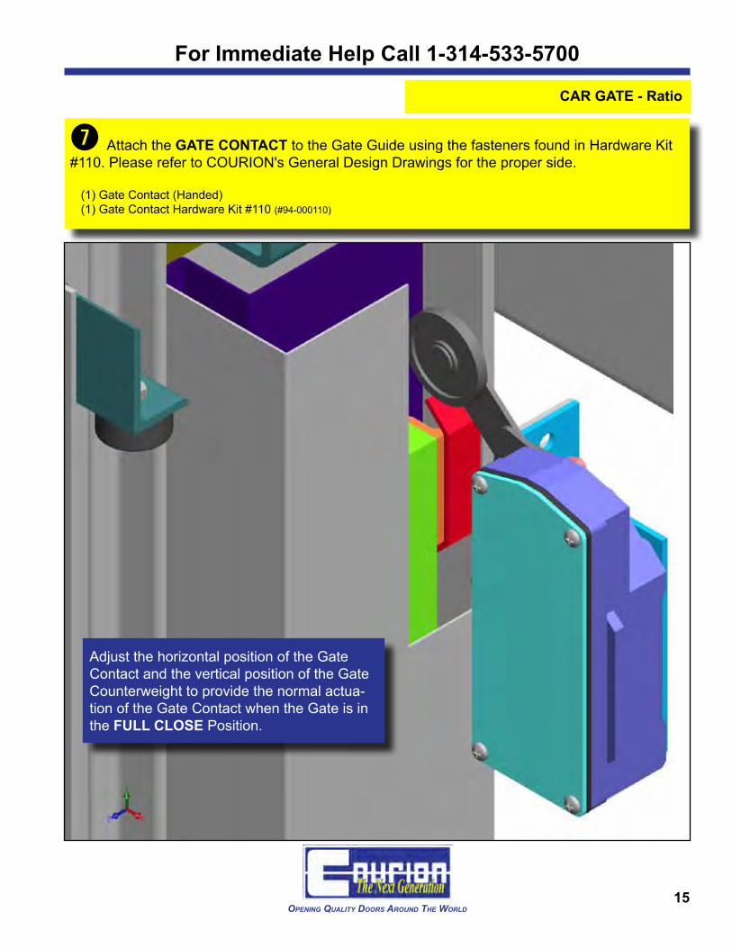
u Attach the GATE CONTACT to the Gate Guide using the fasteners found in Hardware Kit #110. Please refer to COURION's General Design Drawings for the proper side.
(1) Gate Contact (Handed)(1) Gate Contact Hardware Kit #110 (#94-000110)
Adjust the horizontal position of the Gate Contact and the vertical position of the Gate Counterweight to provide the normal actua-tion of the Gate Contact when the Gate is in the FULL CLOSE Position.
For Immediate Help Call 1-800-533-5760
16Opening Quality DOOrs arOunD the WOrlD Ver 052012
CAR GATE - Ratio
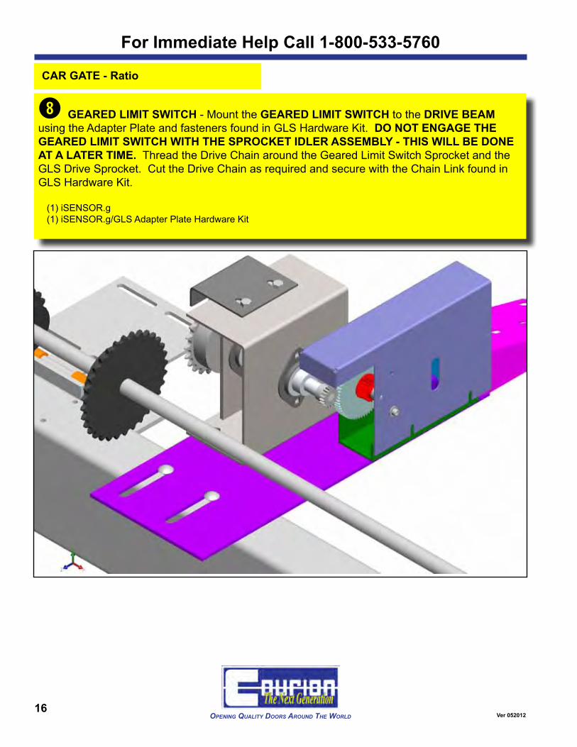
i GEARED LIMIT SWITCH - Mount the GEARED LIMIT SWITCH to the DRIVE BEAM using the Adapter Plate and fasteners found in GLS Hardware Kit. DO NOT ENGAGE THE GEARED LIMIT SWITCH WITH THE SPROCKET IDLER ASSEMBLY - THIS WILL BE DONE AT A LATER TIME. Thread the Drive Chain around the Geared Limit Switch Sprocket and the GLS Drive Sprocket. Cut the Drive Chain as required and secure with the Chain Link found in GLS Hardware Kit.
(1) iSENSOR.g(1) iSENSOR.g/GLS Adapter Plate Hardware Kit

For Immediate Help Call 1-314-533-5700
17Opening Quality DOOrs arOunD the WOrlD
CAR GATE - Ratio
i NEXT GENERATION SYSTEM - Mount the iSENSOR.g to the DRIVE BEAM using the Adapter Plate and fasteners found in GLS Hardware Kit. Thread the Drive Chain around the GLS Sprocket and the iSENSOR.g Sprocket. Cut the Drive Chain as required and secure with the Chain Link found in GLS Hardware Kit.
(1) iSENSOR.g(1) iSENSOR.g/GLS Adapter Plate Hardware Kit

For Immediate Help Call 1-800-533-5760
18Opening Quality DOOrs arOunD the WOrlD Ver 052012
CAR GATE - Ratio
o Mount the GATE MOTOR to the Hinged Motor Bracket on the Drive Side of the Gate Drive Assembly using the fasteners found in Hardware Kit 504. DO NOT TIGHTEN THE FASTEN-ERS. Please refer to Courion's General Design Drawings for the proper side.
(1) Gate Motor(1) Vee Belt (AX-26)(1) Gate Motor Hardware Kit #504 (#94-000504)
Install the Drive Belt(s) between the 2" Motor Pulley and the 7" Drive Shaft Pulley. NOTE: If a 2-groove Motor Pulley and Drive Shaft Pulley have been supplied, use two (2) Drive Belts.
Adjust the Jack Bolt Hex Nuts on the Hinged Motor Bracket to tension the Drive Belts.
For Immediate Help Call 1-314-533-5700
19Opening Quality DOOrs arOunD the WOrlD
CAR GATE - Ratio
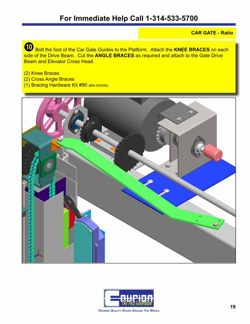
1) Bolt the foot of the Car Gate Guides to the Platform. Attach the KNEE BRACES on each side of the Drive Beam. Cut the ANGLE BRACES as required and attach to the Gate Drive Beam and Elevator Cross Head.
(2) Knee Braces(2) Cross Angle Braces(1) Bracing Hardware Kit #90 (#04-000090)
For Immediate Help Call 1-800-533-5760
20Opening Quality DOOrs arOunD the WOrlD Ver 052012
CAR GATE - Ratio
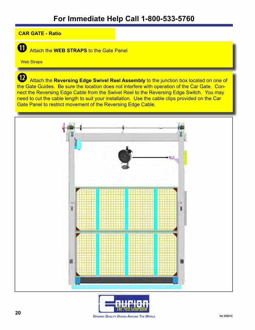
1@ Attach the Reversing Edge Swivel Reel Assembly to the junction box located on one of the Gate Guides. Be sure the location does not interfere with operation of the Car Gate. Con-nect the Reversing Edge Cable from the Swivel Reel to the Reversing Edge Switch. You may need to cut the cable length to suit your installation. Use the cable clips provided on the Car Gate Panel to restrict movement of the Reversing Edge Cable.
1! Attach the WEB STRAPS to the Gate Panel
Web Straps

For Immediate Help Call 1-314-533-5700
21Opening Quality DOOrs arOunD the WOrlD
CAR GATE - Ratio
CAR GATE ADJUSTMENTS - Adjust the Gate Guide Shoes for smooth operation of the Car Gate. The Gate Panels should have no more than 1/16" (2mm) side-to-side play between the Gate Guides.
Reversing Edge Microswitch (N.O.) - Adjust the Hex Head Screw inside the Reversing Edge Switch Box so that the Reversing Edge Microswitch is Normally Closed. Mild Pressure on the Reversing Edge should actuate the Microswitch from Closed to Open.

For Immediate Help Call 1-800-533-5760
22Opening Quality DOOrs arOunD the WOrlD Ver 052012
CAR GATE - Ratio
ADJUST THE GEARED LIMIT SWITCH - If you have a GEARED LIMIT SWITCH, please make the following adjustments.
With the Gate Panel positioned in its 1/2 Open position and the Geared Limit Switch NOT en-gaged with the Idler Sprocket -
1. Rotate the CAM GEAR on the Geared Limit Switch until the arrow points to the roller actua-tor on the Limit Switch.
2. Move the Geared Limit Switch forward so that the CAM GEAR engages the Idler Sprocket Gear. Tighten all bolts.
3. Set the Geared Limit Switch Cams to ac-tuate the Limit Switch when the Car Gate is about 13" (330mm) from FULL OPEN and FULL CLOSE.
Further adjustments will be done after the Gate System is under power.
NEXT GENERATION NOTE
If you have a Gate iSENSOR, please proceed totheiLEARNSystemManualforfinalsetup
and adjustment.

For Immediate Help Call 1-314-533-5700
23Opening Quality DOOrs arOunD the WOrlD
CAR GATE - Ratio
If You Have Courion's NEXT GENERATION Equipment, mount the Gate iDRIVE VFD Control to the top of the Car Enclosure.
(1) Gate iDRIVE VFD Control - Front Gate(1) Gate iDRIVE VFD Control - Rear Gate (when applicable)
IMPORTANT!
The Gate iDRIVE VFD Control must be mounted in close proximity to the Gate iSENSOR and CARE Light Curtain so that their respective cables can reach the necessary connection
points on the Gate iDRIVE.
NEXT GENERATION NOTE
If you have Courion's NEXT GENERATION System, your shipment will contain a Gate iDRIVE VFD Control. See the iLEARN Sys-
tem Manual for additional information.
If You Have Courion's CARE Light Curtain, please proceed to the CARE Light Curtain Installa-tion Manual.
(1pr) CARE Light Curtain System

Opening Quality DOOrs arOunD the WOrlD
the next generatiOn Offreight elevatOr DOOrs
3044 Lambdin AvenueSt. Louis, Missouri 63115
(314) 533-5700 or (800) 533-5760(314) 533-5720 (fax)