HDI 2200 Choke Position Indicator - HDI...
14
HDI 2200 Choke Position Indicator Operations and Maintenance Manual Rev. 1203 www.houstondigital.com email: [email protected] or [email protected] Houston Digital Instruments, Inc. ● 4130 Directors Row ● Houston, TX 77092 Ph 713-688-8555 Fx 713-688-2228
-
Upload
nguyendien -
Category
Documents
-
view
308 -
download
1
Transcript of HDI 2200 Choke Position Indicator - HDI...
HDI 2200 Choke Position Indicator
Operations and Maintenance Manual
Rev. 1203
www.houstondigital.comemail: [email protected] or [email protected]
Houston Digital Instruments, Inc. ● 4130 Directors Row ● Houston, TX 77092 Ph 713-688-8555 Fx 713-688-2228
TABLE OF CONTENTS
SECTION 1 Systems General Information: 1.1 General Information: 1.2 Unpacking and Inspection: 1.3 Precautionary Information: 1.4 Personnel Qualifications: SECTION 2 System Description: 2.1 System Description General: 2.2 System Components: 2.2.1 Choke Position Indicator:
2.2.2 Choke Position Sensors: 2.2.3 Cables
2.3 System Capacities: 2.3.1 Choke Position Indicators: 2.4 System Options
2.4.1. Remote Display: 2.4.2. 4/20 mA Output:
2.4.3 0-1VDC Output: SECTION 3 Installation: 3.1 Components Location: 3.1.1 Console and Sensors: 3.1.2 Cables: 3.2 Mounting Hardware 3.3 Potentiometer Assembly & Installation 3.3.1. General Assembly 3.3.2. Display Installation 3.3.3. Cables SECTION 4 Theory of Operation: 4.1 Choke Position Systems: SECTION 5 Calibration: 5.1 Choke Position Systems: SECTION 6 Corrective Maintenance: 6.1 Choke Position Systems: 6.2 Choke Position Systems Battery Replacement: 6.3 Adjustment Preparation
Houston Digital Instruments, Inc. ● 4130 Directors Row ● Houston, TX 77092 Ph 713-688-8555 Fx 713-688-2228 2
SECTION 7 Preventative Maintenance 7.1 Choke Systems: SECTION 8 Warranty
Houston Digital Instruments, Inc. ● 4130 Directors Row ● Houston, TX 77092 Ph 713-688-8555 Fx 713-688-2228 3
SECTION 1 Systems General Information: 1.1 General Information: This manual describes the installation operation and maintenance of the HDI System #2200 Choke Position Indicating System. This manual shall provide the user with information necessary to properly utilize the Choke Position Indicating System. Included in this manual are all the necessary procedures to install and maintain this Choke Position Indicating System Instrumentation properly. 1.2 Unpacking and Inspection: Upon receipt of the equipment, assure all items are accounted for on the packing list. If any items are missing, immediately inform the freight forwarder. Inspect all items for damage. If any items are damaged immediately inform the freight forwarder and Houston Digital Instruments, Inc. 1.3 Precautionary Information: Assure all directions on the packages are followed during unpacking and handling. 1.4 Personnel Qualifications: This equipment requires experienced personnel to handle, install and maintain. HDI offers a technical training school on their premises if the Customer desires.
Houston Digital Instruments, Inc. ● 4130 Directors Row ● Houston, TX 77092 Ph 713-688-8555 Fx 713-688-2228 4
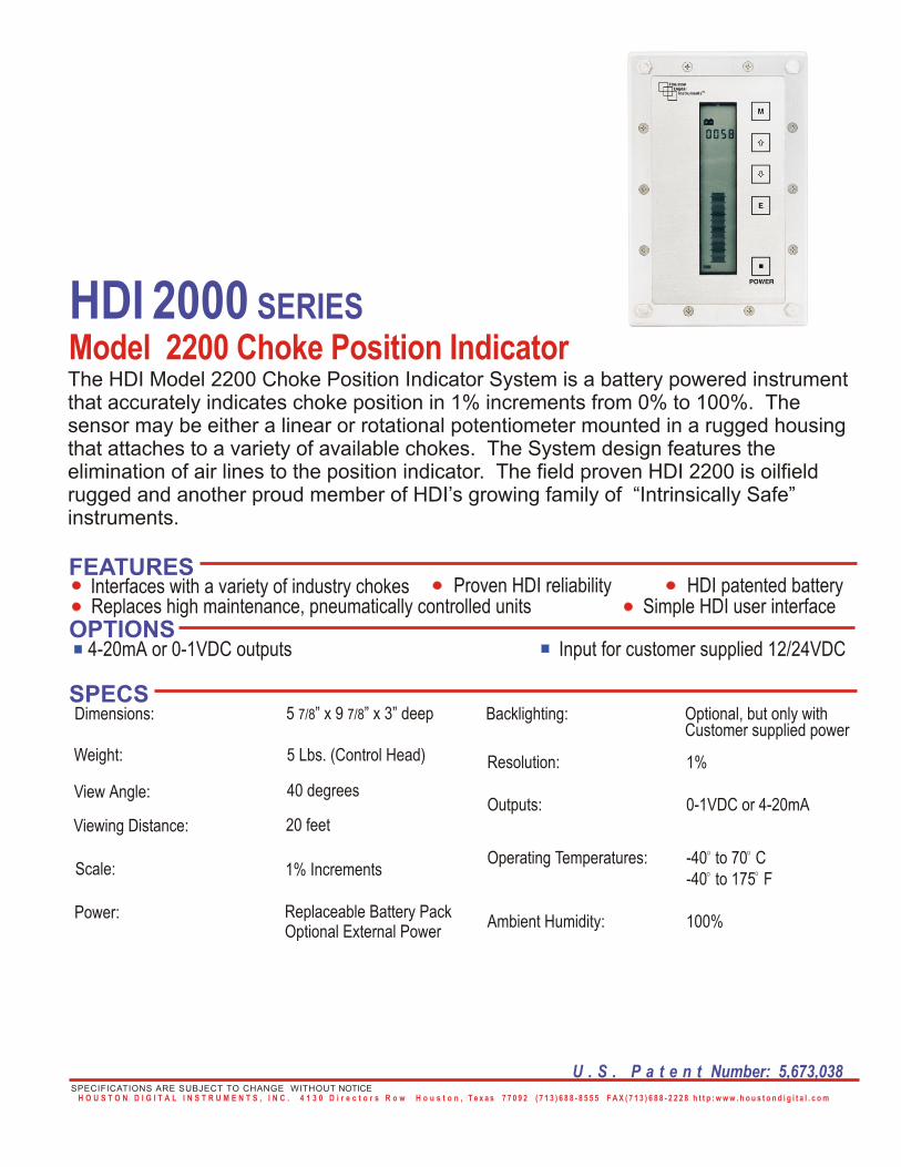
SECTION 2 Systems Description: 2.1 Systems Description: The HDI System #2200 is a Electronic Choke Position Indicating System. The system consists of an electronic potentiometer housed in a stainless steel tube that is located in a stainless steel housing. The assembly is adjustable inside the housing to assure the sensor is located properly. The housing(s) are constructed to adapt to a variety of choke(s). The display is a liquid crystal display (LCD), which includes both a three digit numerical display (for accuracy) and a bar-graph (101 segments) representation (for trend).The electronic bar graph display indicates choke position from closed to open, 0 - 100 percent and in 1/8 graduations. 2.2 System Components: 2.2.1 Choke Position Indicators: Two (2) Choke Position Indicators with numeric and Bar Graph displays (for dual display system-otherwise one indicator). 2.2.2 Choke Position Sensors: Two (2) Choke Position Housings with HDI provided position sensors and mounting systems (for a dual system only. Single systems have a single sensor or transducer). 2.2.3 Cables: All interconnecting cables supplied by HDI.
2.3 System Capacities: 2.3.1 Choke Position Indicators: Choke Position Indicators are rated for 0 to 100 percent or in one-eighth graduations open. 2.4 System Options: Custom designed systems will include, per the customers' request or customers' specifications, certain options required to meet offshore area classifications or specific customer requirements. Each system of this type will be designed to meet specific requirements or classifications and is therefore unique and as such goes beyond the scope of this publication. Barriers or explosion proof junction boxes are not required as the system has been certified intrinsically safe by the Canadian Standards Association (CSA). The following are common examples that may be encountered or requested by customers. HDI offers the following options at additional cost. 2.4.1. Remote Display: Remote displays may be provided to allow secondary indicators at an alternate location at the customer’s request. 2.4.2 4/20 mA Output: HDI offers as an option, a signal current loop providing a 4/20 mA remote output that may be used for chart recorder inputs and/or datalogging.
Houston Digital Instruments, Inc. ● 4130 Directors Row ● Houston, TX 77092 Ph 713-688-8555 Fx 713-688-2228 5
2.4.3 0-1VDC Output: HDI offers as an option, a signal providing a 0-1Vdc remote output that may be used by the customer for chart recorder inputs and/or datalogging. This is a factory installed option and does not require calibration.
Houston Digital Instruments, Inc. ● 4130 Directors Row ● Houston, TX 77092 Ph 713-688-8555 Fx 713-688-2228 6
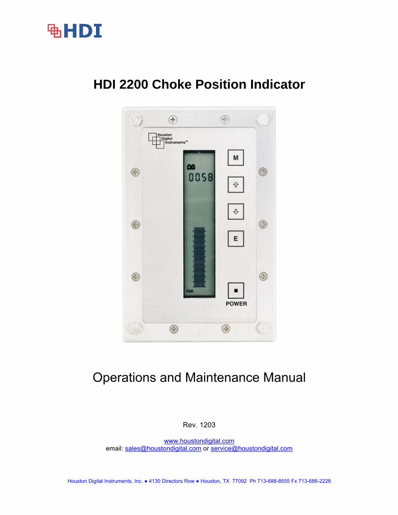
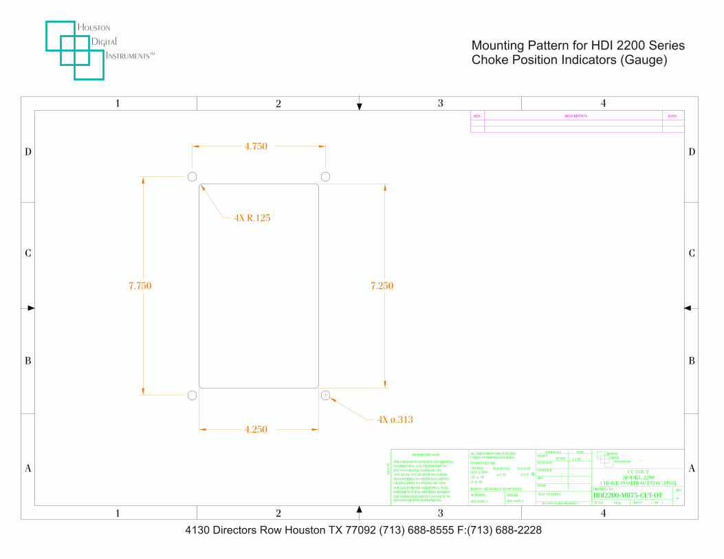
SECTION 3 Installation: 3.1 Components Location: 3.1.1 Control Head and Sensors: The Control Head and Sensors are to be mounted by the Customer at the locations deemed most suitable for such equipment. The system transducer (POTENTIOMETER) comes from the factory as a complete assembly and only requires mounting of the transducer housing using standard practices for such installations. 3.1.2 Cables: All wire lengths from the Panel to the sensors shall be supplied by the customer. 3.2 Mounting Hardware: Provided by HDI, custom fit ups available as option by HDI. 3.3 Choke Position Sensor Assembly and Installation: 3.3.1 Assembly General: The Choke Position Potentiometer and mounting brackets are provided to replace an existing pneumatic regulator choke position system presently in use. This assembly is designed to mount in the original choke position enclosure utilizing the existing hole patterns and mounting hardware. Remove the existing choke position ass'y. Install the new stainless steel housing and potentiometer ass'y with mounting brackets with the existing mounting hardware. The potentiometer shaft must be threaded into the existing choke shaft via the adjustment stud. Leave the potentiometer mounting brackets loose for adjustment. With the choke body in the fully closed position, adjust the potentiometer ass'y to allow 1/8” to 1/4" compression of the shaft into the potentiometer housing and tighten the locknut and the mounting brackets mounting screws. Assure the potentiometer does not bottom out inside its' own housing. Proceed to Calibration. 3.3.2. Choke Position Display: The system gauge is designed to be installed in a 7.25” x 4.25” cut-out hole in the panel. Both the 90 degree and 120 degree bolt patterns are designed into the gauge and all applicable hardware is included. Remove the #10 elastic stopnuts from the 10 X 32 screws, drop the gauge in the appropriate hole and replace the stopnuts. 3.3.3. Cables The system comes complete with wire and connectors made to the customer’s specifications. Simply route the wire from the transducer to the gauge using standard practices, connect the cables to the transducer and gauge, and tighten the collars.
SECTION 4 Theory of Operation:
Houston Digital Instruments, Inc. ● 4130 Directors Row ● Houston, TX 77092 Ph 713-688-8555 Fx 713-688-2228 7
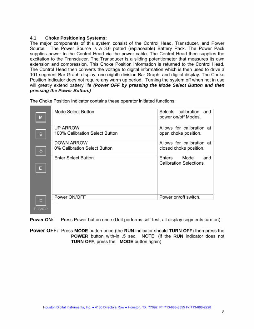
4.1 Choke Positioning Systems: The major components of this system consist of the Control Head, Transducer, and Power Source. The Power Source is a 3.6 potted (replaceable) Battery Pack. The Power Pack supplies power to the Control Head via the power cable. The Control Head then supplies the excitation to the Transducer. The Transducer is a sliding potentiometer that measures its own extension and compression. This Choke Position information is returned to the Control Head. The Control Head then converts the voltage to digital information which is then used to drive a 101 segment Bar Graph display, one-eighth division Bar Graph, and digital display. The Choke Position Indicator does not require any warm up period. Turning the system off when not in use will greatly extend battery life (Power OFF by pressing the Mode Select Button and then pressing the Power Button.) The Choke Position Indicator contains these operator initiated functions:
Mode Select Button
Selects calibration and power on/off Modes.
UP ARROW 100% Calibration Select Button
Allows for calibration at open choke position.
DOWN ARROW 0% Calibration Select Button
Allows for calibration at closed choke position.
Enter Select Button
Enters Mode and Calibration Selections
Power ON/OFF Power on/off switch. .
Power ON: Press Power button once (Unit performs self-test, all display segments turn on) Power OFF: Press MODE button once (the RUN indicator should TURN OFF) then press the POWER button with-in .5 sec. NOTE: (if the RUN indicator does not TURN OFF, press the MODE button again)
Houston Digital Instruments, Inc. ● 4130 Directors Row ● Houston, TX 77092 Ph 713-688-8555 Fx 713-688-2228 8
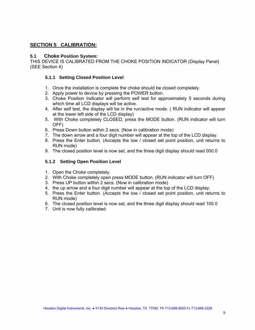
SECTION 5 CALIBRATION: 5.1 Choke Position System: THIS DEVICE IS CALIBRATED FROM THE CHOKE POSITION INDICATOR (Display Panel) (SEE Section 4) 5.1.1 Setting Closed Position Level
1. Once the installation is complete the choke should be closed completely. 2. Apply power to device by pressing the POWER button. 3. Choke Position Indicator will perform self test for approximately 5 seconds during
which time all LCD displays will be active. 4. After self test, the display will be in the run/active mode. ( RUN indicator will appear
at the lower left side of the LCD display) 5. With Choke completely CLOSED, press the MODE button. (RUN indicator will turn
OFF) 6. Press Down button within 2 secs. (Now in calibration mode) 7. The down arrow and a four digit number will appear at the top of the LCD display. 8. Press the Enter button. (Accepts the low / closed set point position, unit returns to
RUN mode) 9. The closed position level is now set, and the three digit display should read 000.0
5.1.2 Setting Open Position Level
1. Open the Choke completely. 2. With Choke completely open press MODE button. (RUN indicator will turn OFF) 3. Press UP button within 2 secs. (Now in calibration mode) 4. the up arrow and a four digit number will appear at the top of the LCD display. 5. Press the Enter button. (Accepts the low / closed set point position, unit returns to
RUN mode) 6. The closed position level is now set, and the three digit display should read 100.0 7. Unit is now fully calibrated.
Houston Digital Instruments, Inc. ● 4130 Directors Row ● Houston, TX 77092 Ph 713-688-8555 Fx 713-688-2228 9
SECTION 6 MAINTENANCE 6.1 Choke Position System The HDI 2200 is a digital electronic gauge designed specifically for Oilfield applications. Allows for calibation at open choke position.Only minor adjustments should be required during instrument should be recalibrated every two (2) years, after a battery change or any change in wiring from the sensor to the gauge. One (1) to two (2) hours per gauge This system does not require any user maintenance. 6.2 Choke Position Systems Battery Replacement: Remove the Canon Connector from the case. Remove the four (4) 1/4"-20 hex screws, nuts and washers and remove the unit from the panel. Remove the 10X32 flat head phillips screws from the front of the unit. Remove the front plate, trim ring plexiglass and gasket. Be careful not to damage the gasket. Lay the gauge to the side and assure it does not get damaged. The battery is secured by velcro to the case. Pull apart the connector that connects the battery to the display. A large screwdriver carefully placed under the battery will pry the battery out of the case. Insert the battery in the case to the velcro. Reconnect the connectors. Replace the display. Connect the canon connector to the rear of the case. Test the system. If the system operates properly reassemble and remount in the reverse order from above. Check Calibration and recalibrate per Section V. 6.3 Tools Required for Calibration and Service: THIS STEP IS NOT NECESSARY WHEN MAKING MINOR ADJUSTMENTS TO A PREVIOUSLY CALIBRATED SYSTEM 1. Screwdriver, Phillips. 2. Screwdriver, Flat Blade . 3. Nutdriver, 3/8".
4. Nutdriver, 7/16". Note: All required tools may be purchased from Houston Digital Instruments, Inc.
Houston Digital Instruments, Inc. ● 4130 Directors Row ● Houston, TX 77092 Ph 713-688-8555 Fx 713-688-2228 10
SECTION 7 Preventative Maintenance: 7.1 Choke Systems: This system does not require any user maintenance. The battery pack will need to be replaced on average every two (2) years. Note: The system calibration should be checked after battery replacement.
Houston Digital Instruments, Inc. ● 4130 Directors Row ● Houston, TX 77092 Ph 713-688-8555 Fx 713-688-2228 11
SECTION 8 Warranty: Houston Digital Instruments, Inc. (HDI) warrants for a period of one year from the date of shipment, HDI's manufactured products to the extent that HDI will replace those parts having defects in material or workmanship when used for the purpose or specification HDI recommends.
HDI will replace or repair, as it deems necessary, any products covered by this warranty, after HDI's examination discloses to its satisfaction, that in fact the products are defective and an adjustment is required. If an adjustment is required, the amount of the adjustment is the net sales price of the defective product. No allowances shall be made for labor or expenses of repairing defective products or damage resulting from same. All products accepted under the provisions of this warranty shall be shipped prepaid to HDI and returned to the customer prepaid by HDI. All products not accepted under the provisions of this warranty shall be shipped prepaid to HDI and returned freight collect. HDI shall not be responsible for repair or replacement of products, resulting from improper handling, storage, installation, misuse, negligence, or use in a manner contrary to the recommendations of HDI.
HDI warrants only the products which it sells of Other Manufacturers to the extent of their warranties. All warranty claims shall be made in writing to the nearest HDI office or authorized factory representative. HDI makes no other warranty of any kind, expressed or implied, and all implied warranties of merchantability or fitness for a particular purpose which exceed HDI's afore-stated obligation are hereby disclaimed by HDI and excluded from this warranty.
This warranty is non transferable and HDI shall not be liable for any damage, injury, loss to property or persons resulting from the use of any HDI's products or equipment whether such damage, injury or loss results from, or is caused by: manner of use, defects in materials or workmanship or otherwise.
Houston Digital Instruments, Inc. ● 4130 Directors Row ● Houston, TX 77092 Ph 713-688-8555 Fx 713-688-2228 12
Embedded EPS
There is embedded EPS on this page. Adobe Acrobat does not support the display of this type of object but it will print intact to a PostScript device.
1 3 4
D
C
B
A
1 2 3 4
A
B
C
D
2
HDI2200-M875-CUT-OTSCALE
DRAWING NO
Auto
CA
D
TRANSFERRED TO OTHER DOCUMENTS.X ± .03
MATERIAL:
SEE NOTE X
REMOVE ALL BURRS & SHARP EDGES.
HOUSTON DIGITAL INSTRUMENTSTHE EXPRESSED WRITTEN CONSENT OF
FOR WHICH IT WAS OBTAINED WITHOUT
FOR ANY PURPOSE OTHER THAN THAT
OR DISCLOSED TO OTHERS OR USED
DO NOT SCALE DRAWING
MGMT
NEXT ASSEMBLY
SEE NOTE X
FINISH:
-
-
-
-
TOLERANCES ARE:
.XX ± .02
.XXX ±.010
ALL DIMENSIONS ARE IN INCHESUNLESS OTHERWISE SPECIFIED.
PROPRIETARY NOTE
AND SHALL NOT BE REPRODUCED OR
HOUSTON DIGITAL INSTRUMENTS
CONFIDENTIAL AND PROPRIETARY TO
THIS DOCUMENT CONTAINS INFORMATION
DECIMAL
APPROVALS
DESIGNED
ENGINEER
DRAWN
±1/32
FRACTIONAL
° MFG
ANGULAR
±1/2
4-4-02
-
-
RENEE
-
-
DATE
CHOKE POSITION INDICATOR
FULL SHEET OF1 1-
REV.
CUTOUT
InstrumentsDigital
MODEL 2200
TM
Houston
REV. DESCRIPTION DATE
4.750
4.250
7.750 7.250
4X R.125
4X ø.313
Mounting Pattern for HDI 2200 SeriesChoke Position Indicators (Gauge)
4130 Directors Row Houston TX 77092 (713) 688-8555 F:(713) 688-2228