HDC II Pleated, Tapered Pore Polypropylene Filter Elements · HDC II Pleated, Tapered Pore...
16
HDC II Pleated, Tapered Pore Polypropylene Filter Elements Economical, Absolute Rated, Long Service Life Pall Corporation
Transcript of HDC II Pleated, Tapered Pore Polypropylene Filter Elements · HDC II Pleated, Tapered Pore...
HDC IIPleated, Tapered Pore
Polypropylene Filter Elements Economical, Absolute Rated,
Long Service Life
Pall Corporation
0-HDC 700d.QxdAA2 5/11/05 8:14 AM Page 1

Table of Contents Page
Introduction – HDC II Filters . . . . . . . . . . . . . . . . . . . . . . . . . . . . . . . . . .3
HDC II Filter Construction . . . . . . . . . . . . . . . . . . . . . . . . . . . . . . . . . . . .4
Feature and Benefits . . . . . . . . . . . . . . . . . . . . . . . . . . . . . . . . . . . . . . . .5
Applications . . . . . . . . . . . . . . . . . . . . . . . . . . . . . . . . . . . . . . . . . . . . . .6-7
Filter Selection Guidelines . . . . . . . . . . . . . . . . . . . . . . . . . . . . . . . . . . . .7
HDC II Industrial Filters . . . . . . . . . . . . . . . . . . . . . . . . . . . . . . . . . . . . .8-9Filter StylesOperating DataPart Numbers
HDC II Sanitary Filters . . . . . . . . . . . . . . . . . . . . . . . . . . . . . . . . . . . . .10-11Filter StylesOperating DataPart Numbers
HDC II Disposable Filter Assemblies . . . . . . . . . . . . . . . . . . . . . . . . . .12-13Filter StylesOperating DataPart Numbers
HDC II Compatibility Data (Table 4) . . . . . . . . . . . . . . . . . . . . . . . . . . . .14
Scientific and Laboratory Services (SLS) . . . . . . . . . . . . . . . . . . . . . . . .15
Pall Corporation . . . . . . . . . . . . . . . . . . . . . . . . . . . . . . . . . . . . . . . . . . .16
HDC® II Filters: Pleated, Profiled, PolypropyleneFilter Elements
Dirt Holding Capacity Increases As Fiber Diameter Decreases
Figure 1 demonstrates how small fiber diameter creates a high dirt-holdingcapacity filter medium.
Figure 1. Variation in Permeability and Dirt Holding Capacity of Non-wovenMedia as a Function of Fiber Diameter (Constant Pore Size).
1 The test procedure used is an adaptation of ANSI B93.31 - 1973 modified todetermine the micron size above which particles are quantitatively removed.
0-HDC 700d.QxdAA2 5/11/05 8:14 AM Page 2
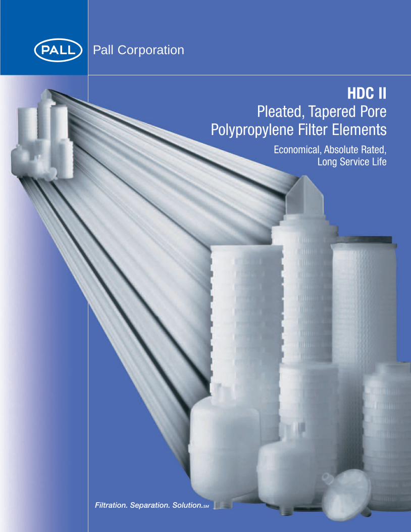
The HDC® II pleated polypropylene filter
uses fibers of varying diameters to produce
a pore size distribution from coarse
(upstream) to fine (downstream).
The construction of the HDC II
filter permits more contaminant
to be trapped in the outer and
inner layers of the medium,
thereby substantially increasing
dirt-holding capacity.
HDC II filters are available in absolute
removal ratings from 0.6 to 70* µm and
are all polypropylene for compatibility
with a wide range of fluids. The filters
have more open area and pores than
filters of similar appearance. Based upon
tests both in the field and in Pall labora-
tories, HDC II elements can be expected
to yield longer service lives compared
with products at equal efficiencies.
3
HDC II Filter Medium
Figure 2 illustrates thevarying fiber diameterused in the HDC II filter.This proprietaryconstruction enablesthe filter cartridge tohold more contaminantand have longer life.
* One micrometer (µm)referenced as a micron is1/1000 of a millimeter. Thesmallest visible particle isabout 30-50 µm in diameter.
Downstream Layer
Figure 2
Middle Layer Outermost Layer
0-HDC 700d.QxdAA2 5/11/05 8:14 AM Page 3
4
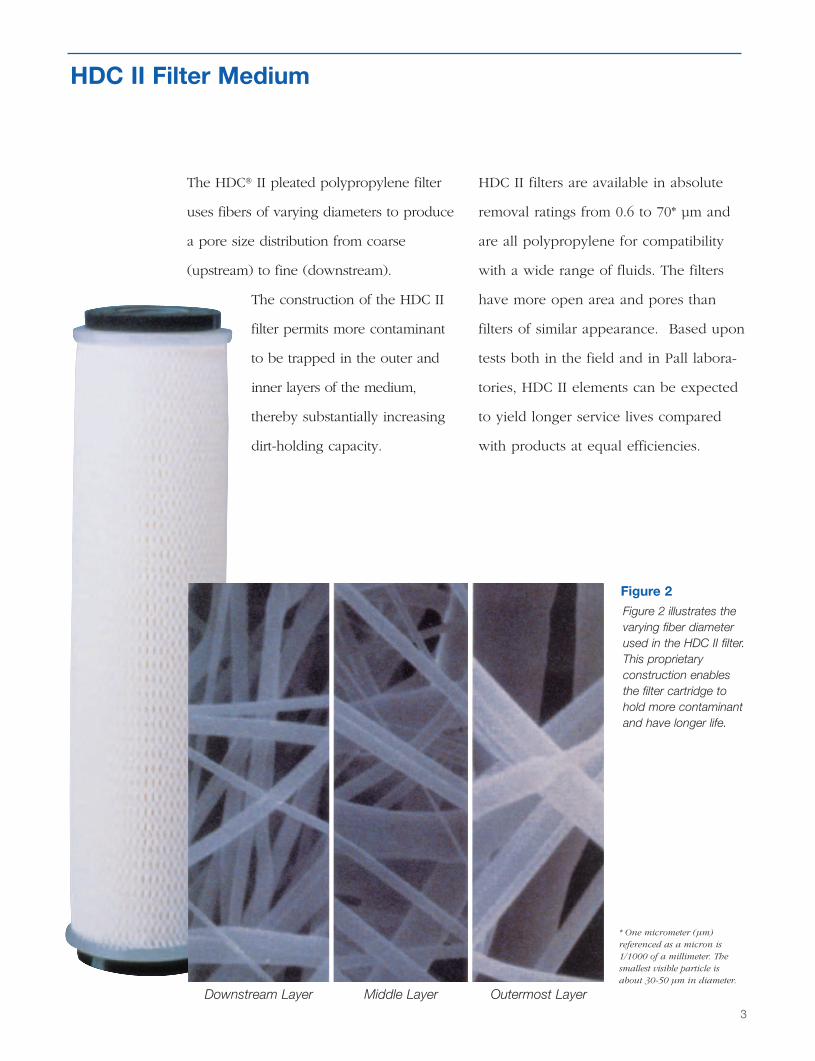
Each grade of HDC II element is carefully constructed for optimal service life,efficiency and integrity.
Filter Construction
Polypropylene molded outer cage (10” elements) or netting (>10” elements) protects against mechanical damageand inadvertent reverse flow.
Polypropylene molded inner coreprovides mechanical strength underdynamic service conditions.
Polypropylene end caps are melt sealed to filter medium and innercore using Pall’s proprietary meltwelding process that uses no additional material.
Pleated polypropylene filter mediumpack provides maximum effectivefilter area for longest possible service life.
0-HDC 700d.QxdAA2 5/11/05 8:14 AM Page 4

5
Absolute Rated• 99.98% absolute removal efficiency* • Consistent, verifiable filtration
Varied Fiber Diameter• High dirt holding capacity• Low cost per gallon or volume of filtrate
Fixed Pore Structure• No solids unloading• No fiber migration
Pure Polypropylene Construction• Wide chemical compatibility• No surfactants or binder resins• Meets FDA requirements• Low protein binding
“P” Optimization for Pharmaceuticals• Materials of Construction:
- All polypropylene components meet thespecifications for Biological Safety as per USP for Class VI 121°C plastic – gaskets/O-rings excluded
- Meet incoming materials QC inspection- Manufactured from materials which are
listed for food contact application in titles of the US code of Federal Regulation
• Fabrication Integrity:- Prefilters lot sampled for manufacturing
integrity- Lot samples are multiple steam cycle
tested to assure element integrity
• Manufacturing Environment:- A controlled environment under
cleanroom conditions- ISO 9001 Registered - Total Quality Management system
• Performance and Qualification Tests:- Cleanliness: Meets current USP limit
under Particulate Matter in injectionsNon-fiber-releasing per CFR Title 21, parts 211.72 and 210.3 (b) (6)
- Oxidizable Substances:Meets current USP requirements under Purified Water after flushingMeets current USP requirements under Sterile Purified Water after flushing
- Bacterial Endotoxins:Meets current USP requirements under Bacterial endotoxins test
• Documentation and Traceability: Certificate of Test provided with each ‘P-Rated’ filter - Identification provided on every box,
bag and filter label that includes:Part NumberLot Number
- Installation instructions and steaming procedures provided with each filter
- Lot and serial number for full traceability
• Packaging:Factory sealed protective packaging
Features and Benefits
Tapered pores provide an effective prefiltration layer on the outer diam-eter while smaller constant poreson the inner diameter provideabsolute removal efficiency.
Downstream polypropylenedrainage/support layerminimizes pressure loss.
Upstream polypropylenedrainage/support layeroptimizes filter life.
0-HDC 700d.QxdAA2 5/11/05 8:14 AM Page 5
6
Applications
Pharmaceuticals: small and large volumeparenterals, ophthalmics, and oral medications
Biologicals: serum and serum fractions,tissue culture media, vaccine preparations,microbiological growth media, media make-upwater and diagnostic sera
Veterinary: parenterals and therapeutic sera
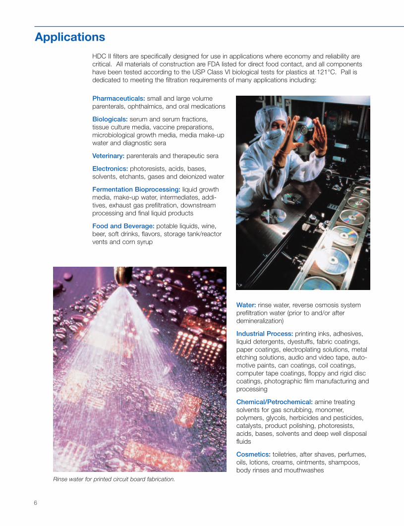
Electronics: photoresists, acids, bases,solvents, etchants, gases and deionized water
Fermentation Bioprocessing: liquid growthmedia, make-up water, intermediates, addi-tives, exhaust gas prefiltration, downstreamprocessing and final liquid products
Food and Beverage: potable liquids, wine,beer, soft drinks, flavors, storage tank/reactorvents and corn syrup
HDC II filters are specifically designed for use in applications where economy and reliability arecritical. All materials of construction are FDA listed for direct food contact, and all componentshave been tested according to the USP Class VI biological tests for plastics at 121°C. Pall isdedicated to meeting the filtration requirements of many applications including:
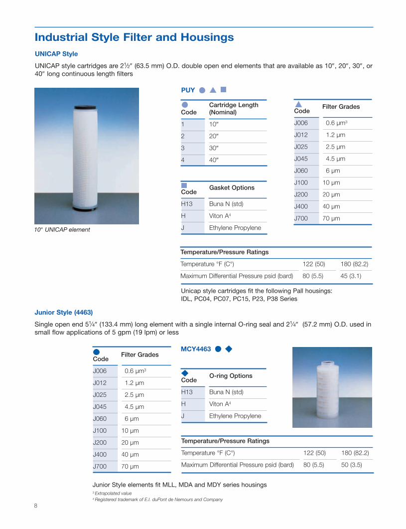
Rinse water for printed circuit board fabrication.
Water: rinse water, reverse osmosis systemprefiltration water (prior to and/or afterdemineralization)
Industrial Process: printing inks, adhesives,liquid detergents, dyestuffs, fabric coatings,paper coatings, electroplating solutions, metaletching solutions, audio and video tape, auto-motive paints, can coatings, coil coatings,computer tape coatings, floppy and rigid disccoatings, photographic film manufacturing andprocessing
Chemical/Petrochemical: amine treatingsolvents for gas scrubbing, monomer,polymers, glycols, herbicides and pesticides,catalysts, product polishing, photoresists,acids, bases, solvents and deep well disposalfluids
Cosmetics: toiletries, after shaves, perfumes,oils, lotions, creams, ointments, shampoos,body rinses and mouthwashes
0-HDC 700d.QxdAA2 5/11/05 8:14 AM Page 6

7
Filter Selection GuideTo facilitate selection of the best HDC II media and toensure optimum performance, it is recommended that theflow requirements and differential pressure be considered.
Follow this simple procedure to select a filter:1 Select the preferred filter style and absolute removal
rating:Industrial: pages 8-9Sanitary: pages 10-11Disposable Filter Assemblies: pages 12-13
2. Determine the required number of elements by dividingthe required flow rate by the typical aqueous flow perelement using one of the following tables:
Industrial: Table 1ASanitary: Table 2ASmall Flow Encapsulated Disposable Assemblies: Table 3
Verify allowable clean pressure drop by multiplying therequired flow rate by the clean pressure drop per GPMfound in the tables listed above in 2. Divide by thenumber of elements calculated in step 2.
3. For Industrial and Sanitary applications, refer to hous-ing Tables 1B and 2B, respectively, to determineappropriate housing size based upon system flow ratesand number of filter elements calculated in step 2[above].
4. Refer to pages 10,12 and 14 for complete orderinginformation on Industrial Elements, Sanitary Elementsand Disposable Assemblies, respectively.
Example:A filtration system is required for 10 µm absolute removalin a UNICAP style. The flow rate is 75 GPM and allow-able clean pressure drop is 5 psid.
According to table 1a, fifteen, 10” filter elements are needed.
75 GPM ÷ 5 GPM = (15) 10” filters
10” modules
To verify the clean pressure drop of the system, divide thesystem flow rate by the number of elements calculated in2 and multiply by the clean pressure drop per 10” filter:
75 GPM x 0.06 PSID = 0.3 PSID
(15) 10” GPM/10”
In Table 1B, a PC07 Series housing for UNICAP style ele-ments is recommended for a flow rate of up to 225 GPM.A stacking array, which will accept a minimum of fifteen10” filter elements, is required. Therefore, the PC07 hous-ing series with a stacking array of 7 x 30” will meet therequirements. The part number for this filter element is
PUY3J100J
Note: optimum sizing depends upon available system pressure and nature ofcontaminant. The housing pressure drop must be added to the element pressuredrop. Therefore, it is recommended to review your filter selection with aPall representative.
Polymer: monomers, quench water, slurry additives,delusterants, slip agents, deionized water, solvents,spin finishes and aqueous salt solutions
Polymer film manufacturing
Power Generation: make-up water, steam generatorblowdown prefilters
Coolant water filtration at a nuclear power plant
0-HDC 700d.QxdAA2 5/11/05 8:14 AM Page 7
8
Cartridge LengthCode (Nominal)
1 10″
2 20″
3 30″
4 40″
Gasket OptionsCode
H13 Buna N (std)
H Viton A4
J Ethylene Propylene
Filter GradesCode
J006 0.6 µm3
J012 1.2 µm
J025 2.5 µm
J045 4.5 µm
J060 6 µm
J100 10 µm
J200 20 µm
J400 40 µm
J700 70 µm
Temperature/Pressure Ratings
Temperature °F (C°) 122 (50) 180 (82.2)
Maximum Differential Pressure psid (bard) 80 (5.5) 45 (3.1)
Unicap style cartridges fit the following Pall housings:IDL, PC04, PC07, PC15, P23, P38 Series
Junior Style elements fit MLL, MDA and MDY series housings3 Extrapolated value4 Registered trademark of E.I. duPont de Nemours and Company
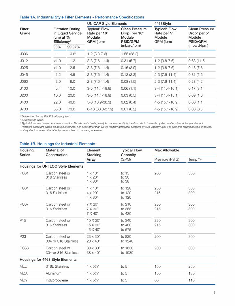
10″ UNICAP element
UNICAP Style
UNICAP style cartridges are 21⁄2″ (63.5 mm) O.D. double open end elements that are available as 10″, 20″, 30″, or40″ long continuous length filters
Junior Style (4463)
Single open end 51⁄4″ (133.4 mm) long element with a single internal O-ring seal and 21⁄4″ (57.2 mm) O.D. used insmall flow applications of 5 gpm (19 lpm) or less
PUY
MCY4463
O-ring OptionsCode
H13 Buna N (std)
H Viton A4
J Ethylene Propylene
Filter GradesCode
J006 0.6 µm3
J012 1.2 µm
J025 2.5 µm
J045 4.5 µm
J060 6 µm
J100 10 µm
J200 20 µm
J400 40 µm
J700 70 µm
Temperature/Pressure Ratings
Temperature °F (C°) 122 (50) 180 (82.2)
Maximum Differential Pressure psid (bard) 80 (5.5) 50 (3.5)
Industrial Style Filter and Housings
0-HDC 700d.QxdAA2 5/11/05 8:14 AM Page 8
9
UNICAP Style Elements 4463Style
Filter Filtration Rating Typical6 Flow Clean Pressure Typical6 Flow Clean PressureGrade in Liquid Service Rate per 10″ Drop7 per 10″ Rate per 5″ Drop7 per 5″
(µm) at % Module Module Module ModuleEfficiency5 GPM (lpm) PSID/GPM GPM (lpm) PSID/GPM
90% 99.97% (mbard/lpm) (mbard/lpm)
J006 - 0.6* 1-2 (3.8-7.6) 1.55 (28.2) - -
J012 <1.0 1.2 2-3 (7.6-11.4) 0.31 (5.7) 1-2 (3.8-7.6) 0.63 (11.5)
J025 <1.0 2.5 2-3 (7.6-11.4) 0.16 (2.9) 1-2 (3.8-7.6) 0.43 (7.8)
J045 1.2 4.5 2-3 (7.6-11.4) 0.12 (2.2) 2-3 (7.6-11.4) 0.31 (5.6)
J060 3.0 6.0 2-3 (7.6-11.4) 0.08 (1.5) 2-3 (7.6-11.4) 0.23 (4.2)
J100 5.4 10.0 3-5 (11.4-18.9) 0.06 (1.1) 3-4 (11.4-15.1) 0.17 (3.1)
J200 10.0 20.0 3-5 (11.4-18.9) 0.03 (0.5) 3-4 (11.4-15.1) 0.09 (1.6)
J400 22.0 40.0 5-8 (18.9-30.3) 0.02 (0.4) 4-5 (15.1-18.9) 0.06 (1.1)
J700 35.0 70.0 8-10 (30.3-37.9) 0.01 (0.2) 4-5 (15.1-18.9) 0.03 (0.5)
5 Determined by the Pall F-2 efficiency test.* Extrapolated value. 6 Typical flows are based on aqueous service. For elements having multiple modules, multiply the flow rate in the table by the number of modules per element.7 Pressure drops are based on aqueous service. For fluids other than water, multiply differential pressure by fluid viscosity (cp). For elements having multiple modules, multiply the flow rate in the table by the number of modules per element.
Table 1A. Industrial Style Filter Elements - Performance Specifications
Table 1B. Housings for Industrial Elements
Housing Material of Element Typical Flow Max Allowable Series Construction Stacking Capacity
Array (GPM) Pressure (PSIG) Temp °F
Housings for UNI LOC Style Elements
PC01 Carbon steel or 1 x 10” to 15 200 300316 Stainless 1 x 20” to 30
1 x 30” to 38
PC04 Carbon steel or 4 x 10” to 120 230 300316 Stainless 4 x 20” to 120 215 300
4 x 30” to 120
PC07 Carbon steel or 7 X 20” to 210 230 300316 Stainless 7 X 30” to 368 215 300
7 X 40” to 420
P15 Carbon steel or 15 X 20” to 340 230 300316 Stainless 15 X 30” to 480 215 300
15 X 40” to 675
P23 Carbon steel or 23 x 30” to 820 200 300304 or 316 Stainless 23 x 40” to 1240
PC38 Carbon steel or 38 x 30” to 1630 200 300304 or 316 Stainless 38 x 40” to 1930
Housings for 4463 Style Elements
MLL 316L Stainless 1 x 51⁄4” to 5 150 250
MDA Aluminum 1 x 51⁄4” to 5 150 130
MDY Polypropylene 1 x 51⁄4” to 5 60 110
0-HDC 700d.QxdAA2 5/11/05 8:14 AM Page 9
10
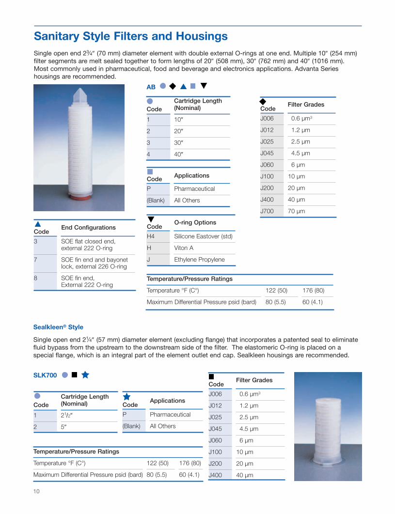
Single open end 23⁄4″ (70 mm) diameter element with double external O-rings at one end. Multiple 10″ (254 mm)filter segments are melt sealed together to form lengths of 20″ (508 mm), 30″ (762 mm) and 40″ (1016 mm).Most commonly used in pharmaceutical, food and beverage and electronics applications. Advanta Serieshousings are recommended.
Sealkleen® Style
Single open end 21⁄4″ (57 mm) diameter element (excluding flange) that incorporates a patented seal to eliminatefluid bypass from the upstream to the downstream side of the filter. The elastomeric O-ring is placed on aspecial flange, which is an integral part of the element outlet end cap. Sealkleen housings are recommended.
Cartridge LengthCode (Nominal)
1 10″
2 20″
3 30″
4 40″
AB
Cartridge LengthCode (Nominal)
1 21/2″
2 5″
SLK700
Filter GradesCode
J006 0.6 µm3
J012 1.2 µm
J025 2.5 µm
J045 4.5 µm
J060 6 µm
J100 10 µm
J200 20 µm
J400 40 µm
J700 70 µm
Filter GradesCode
J006 0.6 µm3
J012 1.2 µm
J025 2.5 µm
J045 4.5 µm
J060 6 µm
J100 10 µm
J200 20 µm
J400 40 µm
O-ring OptionsCode
H4 Silicone Eastover (std)
H Viton A
J Ethylene Propylene
ApplicationsCode
P Pharmaceutical
(Blank) All Others
ApplicationsCode
P Pharmaceutical
(Blank) All Others
End ConfigurationsCode
3 SOE flat closed end,external 222 O-ring
7 SOE fin end and bayonetlock, external 226 O-ring
8 SOE fin end,External 222 O-ring
Temperature/Pressure Ratings
Temperature °F (C°) 122 (50) 176 (80)
Maximum Differential Pressure psid (bard) 80 (5.5) 60 (4.1)
Temperature/Pressure Ratings
Temperature °F (C°) 122 (50) 176 (80)
Maximum Differential Pressure psid (bard) 80 (5.5) 60 (4.1)
Sanitary Style Filters and Housings
0-HDC 700d.QxdAA2 5/11/05 8:14 AM Page 10
11
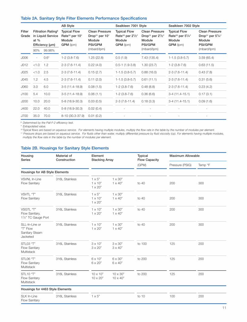
Table 2A. Sanitary Style Filter Elements Performance Specifications
AB Style Sealkleen 7001 Style Sealkleen 7002 Style
Filter Filtration Rating9 Typical Flow Clean Pressure Typical Flow Clean Pressure Typical Flow Clean PressureGrade in Liquid Service Rate10 per 10″ Drop11 per 10″ Rate10 per 21/2″ Drop11 per 21/2″ Rate10 per 51/4″ Drop11 per 51/4″
at % Module Module Module Module Module ModuleEfficiency (µm) GPM (lpm) PSI/GPM GPM (lpm) PSI/GPM GPM (lpm) PSI/GPM
90% 99.98% (mbard/lpm) (mbard/lpm) (mbard/lpm)
J006 - 0.6* 1-2 (3.8-7.6) 1.25 (22.8) 0.5 (1.9) 7.43 (135.4) 1-1.5 (3.8-5.7) 3.59 (65.4)
J012 <1.0 1.2 2-3 (7.6-11.4) 0.22 (4.0) 0.5-1 (1.9-3.8) 1.30 (23.7) 1-2 (3.8-7.6) 0.63 (11.5)
J025 <1.0 2.5 2-3 (7.6-11.4) 0.15 (2.7) 1-1.5 (3.8-5.7) 0.88 (16.0) 2-3 (7.6-11.4) 0.43 (7.8)
J045 1.2 4.5 2-3 (7.6-11.4) 0.11 (2.0) 1-1.5 (3.8-5.7) 0.61 (11.1) 2-3 (7.6-11.4) 0.31 (5.6)
J060 3.0 6.0 3-5 (11.4-18.9) 0.08 (1.5) 1-2 (3.8-7.6) 0.48 (8.8) 2-3 (7.6-11.4) 0.23 (4.2)
J100 5.4 10.0 3-5 (11.4-18.9) 0.06 (1.1) 1-2 (3.8-7.6) 0.36 (6.6) 3-4 (11.4-15.1) 0.17 (3.1)
J200 10.0 20.0 5-8 (18.9-30.3) 0.03 (0.5) 2-3 (7.6-11.4) 0.18 (3.3) 3-4 (11.4-15.1) 0.09 (1.6)
J400 22.0 40.0 5-8 (18.9-30.3) 0.02 (0.4) - - - -
J700 35.0 70.0 8-10 (30.3-37.9) 0.01 (0.2) - - - -
9 Determined by the Pall F-2 efficiency test.* Extrapolated value. 10 Typical flows are based on aqueous service. For elements having multiple modules, multiply the flow rate in the table by the number of modules per element.11 Pressure drops are based on aqueous service. For fluids other than water, multiply differential pressure by fluid viscosity (cp). For elements having multiple modules,
multiply the flow rate in the table by the number of modules per element.
Table 2B. Housings for Sanitary Style Elements
Housing Material of Element Typical Maximum Allowable Series Construction Stacking Array Flow Capacity
(GPM) Pressure (PSIG) Temp °F
Housings for AB Style Elements
VSVNL In-Line 316L Stainless 1 x 5” 1 x 30”Flow Sanitary 1 x 10” 1 x 40” to 40 200 300
1 x 20”
VSVTL “T” 316L Stainless 1 x 5” 1 x 30”Flow Sanitary 1 x 10” 1 x 40” to 40 200 300
1 x 20”
VSGTL “T” 316L Stainless 1 x 10” 1 x 30” to 40 200 300Flow Sanitary, 1 x 20” 1 x 40”11⁄2” TC Gauge Port
SLL-In-Line or 316L Stainless 1 x 10” 1 x 30” to 40 200 300“T” Flow 1 x 20” 1 x 40”Sanitary SteamJacketed
STL03 “T” 316L Stainless 3 x 10” 3 x 30” to 100 125 200Flow Sanitary 3 x 20” 3 x 40”Multistack
STL06 “T” 316L Stainless 6 x 10” 6 x 30” to 200 125 200Flow Sanitary 6 x 20” 6 x 40”Multistack
STL10 “T” 316L Stainless 10 x 10” 10 x 30” to 200 125 200Flow Sanitary 10 x 20” 10 x 40”Multistack
Housings for 4463 Style Elements
SLK In-Line 316L Stainless 1 x 5” to 10 100 200Flow Sanitary
0-HDC 700d.QxdAA2 5/11/05 8:14 AM Page 11

12
KLEENPAK® Style
HDC II Filter elements are melt sealed into small, disposable polypropylene filter housings and are available invarious lengths and diameters. Maximum operating pressure is 50 psig (3.5 bar) in gas and 75 psig (5.2 bar) inliquid at 100°F (37.8°C). Specifically designed for small volume batch sizes, these filter assemblies satisfy a widerange of laboratory, pilot plant and production scale applications.
DFA® Style
FLF® Style
Filter Area12 ft2 (m2)
Code (Nominal)
1 0.5 (0.05)
2 1.0 (0.1)
3 2.0 (0.2)
4 5.0 (0.5)
KA P
DFA 001Dimensions (nominal):Outside Diameter: 23⁄4″ (70 mm)Length: 4″ (102 mm)
FLF6601Dimensions (nominal):Outside Diameter: 21⁄2″ (63.5 mm)Length: 31⁄4″ (83 mm)
Code Connection Styles
3 3⁄8″ Hosebarb
4 1⁄4″ NPT
Code Applications
P Pharmaceutical
(Blank) All Others
Code Applications
P Pharmaceutical
(Blank) All Others
Connection Styles
Code KA1 KA2 KA3Connector Length Length LengthStyles Inches Inches Inches
(mm) (mm) (mm)
1 1-11⁄2″ 4.6″ (117) 6.2″ (158) 6.9″ (175)Tri-Clamp13
2 1⁄4-1⁄2″ Hosebarb 6.2″ (158) 7.8″ (198) -
3 1/4″ NPT 5.6″ (141) 7.2″ (182) -
4 6 mm Walther - -Connection(British)
5 12 mm Walther - - 8.6″ (219)Connection(British)
6 3/8″ Hosebarb - - 8.3 (211)
Filter GradesCode
J006 0.6 µm
J012 1.2 µm
J025 2.5 µm
J045 4.5 µm
J060 6 µm
J100 10 µm
J200 20 µm
J400 40 µm
Filter GradesCode
J006 0.6 µm14
J012 1.2 µm
J025 2.5 µm
J045 4.5 µm
J060 6 µm
J100 10 µm
Disposable Filter Assemblies
Filter GradesCode
J006 0.6 µm14
J012 1.2 µm
J025 2.5 µm
J045 4.5 µm
J060 6 µm
J100 10 µm
J200 20 µm
J400 40 µm
J700 70 µm14 Extrapolated value
12 Refer to the Connection/Length table for cartridge length.13 Registered trademark of Tri-Clover, Inc.
0-HDC 700d.QxdAA2 5/11/05 8:14 AM Page 12

13
DFA FLFFilter Liquid Filtration Typical16 Clean17 Typical16 Clean18
Grade Rating at % Flow Rate Pressure Drop Flow Rate Pressure DropEfficiency15 (µm) GPM (lpm) PSID/GPM GPM (lpm) PSID/GPM
90% 99.98% (mbard/lpm) (mbard/lpm)
J006 - 0.6* 0.5 (1.9) 7.43 (135.4) 0.2 (0.76) 20.38 (371.3)
J012 <1.0 1.2 0.5-1 (1.9-3.8) 1.30 (23.7) 0.2 (0.76) 3.58 (65.2)
J025 <1.0 2.5 1-1.5 (3.8-5.7) 0.88 (16.0) 0.3 (1.14) 2.43 (44.3)
J045 1.2 4.5 1-1.5 (3.8-5.7) 0.66 (12.0) 0.3 (1.14) 1.78 (32.4)
J060 3.0 6.0 1-2 (3.8-7.6) 0.48 (8.7) 0.4 (1.51) 1.30 (23.7)
J100 5.4 10 1-2 (3.8-7.6) 0.36 (6.6) 0.4 (1.51) 0.97 (17.7)
J200 10 20 2-3 (7.6-11.4) 0.18 (3.3) - -
J400 22 40 2-3 (7.6-11.4) 0.12 (2.2) - -
J700 35 70 2-3 (7.6-11.4) 0.06 (1.1) - -
* Extrapolated Value15 Determined by the Pall F-2 efficiency test. J700 used the maximum spherical particle passed test.16 Typical flows are based on aqueous service.17 For fluids other than water, multiply differential pressure by fluid viscosity (cp).
Add housing ∆P: PSID=0.312 (GPM)2, for fluids other than water, multiply housing ∆P by specific gravity.18 For fluids other than water, multiply differential pressure by fluid viscosity (cp).
Add housing ∆P: PSID=0.624 (GPM)2, for fluids other than water, multiply housing ∆P by specific gravity.
Table 3. Disposable Filter Assemblies - Performance Specifications
A rating method developed at Oklahoma State Universityin the 1970s (OSU F-2 Test Method) has received wideacceptance for use on lubricating and hydraulic fluids.Pall Corporation extensively uses this method for oils,and has adapted it for use with water in the 0.5 to 25 µmrange. A second modification uses oil and covers therange from 25 to 70 µm.
Comparing Dirt Capacities
The OSU F-2 test data can be used to obtain verymeaningful comparisons of efficiency between filters ofvarying types and from various sources. The dirt holdingcapacity data, however, correlates only very roughly withactual service life. Bearing in mind the approximatenature of these data, various competitive filter elementsof equal efficiencies, as determined by the F-2 Test, werecompared with HDC II elements. These comparisonsindicated that when elements with equal F-2 efficienciesare compared, the service life of HDC II elements couldbe expected to be up to four times longer.
Performance DataRemoval Ratings
There is no universally accepted system for determining removal ratings of cartridge filters in liquid service.
0-HDC 700d.QxdAA2 5/11/05 8:15 AM Page 13
14
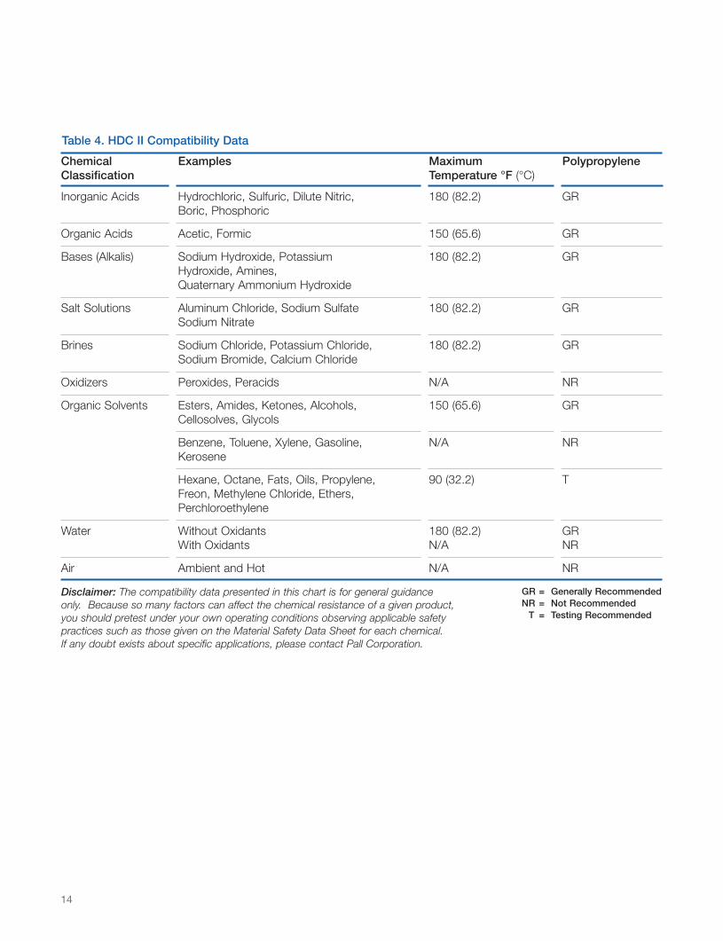
Table 4. HDC II Compatibility Data
Chemical Examples Maximum PolypropyleneClassification Temperature °F (°C)
Inorganic Acids Hydrochloric, Sulfuric, Dilute Nitric, 180 (82.2) GRBoric, Phosphoric
Organic Acids Acetic, Formic 150 (65.6) GR
Bases (Alkalis) Sodium Hydroxide, Potassium 180 (82.2) GRHydroxide, Amines,Quaternary Ammonium Hydroxide
Salt Solutions Aluminum Chloride, Sodium Sulfate 180 (82.2) GRSodium Nitrate
Brines Sodium Chloride, Potassium Chloride, 180 (82.2) GRSodium Bromide, Calcium Chloride
Oxidizers Peroxides, Peracids N/A NR
Organic Solvents Esters, Amides, Ketones, Alcohols, 150 (65.6) GRCellosolves, Glycols
Benzene, Toluene, Xylene, Gasoline, N/A NRKerosene
Hexane, Octane, Fats, Oils, Propylene, 90 (32.2) TFreon, Methylene Chloride, Ethers,Perchloroethylene
Water Without Oxidants 180 (82.2) GRWith Oxidants N/A NR
Air Ambient and Hot N/A NR
GR = Generally RecommendedNR = Not Recommended
T = Testing Recommended
Disclaimer: The compatibility data presented in this chart is for general guidanceonly. Because so many factors can affect the chemical resistance of a given product,you should pretest under your own operating conditions observing applicable safetypractices such as those given on the Material Safety Data Sheet for each chemical.If any doubt exists about specific applications, please contact Pall Corporation.
0-HDC 700d.QxdAA2 5/11/05 8:15 AM Page 14
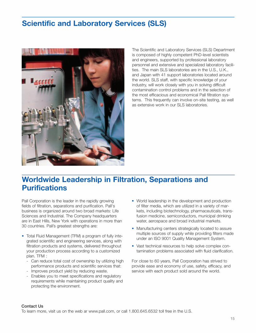
Worldwide Leadership in Filtration, Separations andPurifications
The Scientific and Laboratory Services (SLS) Departmentis composed of highly competent PhD-level scientistsand engineers, supported by professional laboratorypersonnel and extensive and specialized laboratory facili-ties. The main SLS laboratories are in the U.S., U.K.,and Japan with 41 support laboratories located aroundthe world. SLS staff, with specific knowledge of yourindustry, will work closely with you in solving difficultcontamination control problems and in the selection ofthe most efficacious and economical Pall filtration sys-tems. This frequently can involve on-site testing, as wellas extensive work in our SLS laboratories.
Pall Corporation is the leader in the rapidly growingfields of filtration, separations and purification. Pall'sbusiness is organized around two broad markets: LifeSciences and Industrial. The Company headquartersare in East Hills, New York with operations in more than30 countries. Pall’s greatest strengths are:
• Total Fluid Management (TFM) a program of fully inte-grated scientific and engineering services, along withfiltration products and systems, delivered throughoutyour production process according to a customizedplan. TFM :- Can reduce total cost of ownership by utilizing high
performance products and scientific services that:- Improves product yield by reducing waste.- Enables you to meet specifications and regulatory
requirements while maintaining product quality and protecting the environment.
• World leadership in the development and productionof filter media, which are utilized in a variety of mar-kets, including biotechnology, pharmaceuticals, trans-fusion medicine, semiconductors, municipal drinkingwater, aerospace and broad industrial markets.
• Manufacturing centers strategically located to assuremultiple sources of supply while providing filters madeunder an ISO 9001 Quality Management System.
• Vast technical resources to help solve complex con-tamination problems associated with fluid clarification.
For close to 60 years, Pall Corporation has strived toprovide ease and economy of use, safety, efficacy, andservice with each product sold around the world.
Scientific and Laboratory Services (SLS)
Contact UsTo learn more, visit us on the web ar www.pall.com, or call 1.800.645.6532 toll free in the U.S.
15
0-HDC 700d.QxdAA2 5/11/05 8:15 AM Page 15

2200 Northern BoulevardEast Hills, New York 11548-12891.800.645.6532 toll free516.484.5400 phone 516.484.0364 [email protected] email
Visit us on the Web at www.pall.com
Pall Corporation has offices and plants throughout the world in locations including:Argentina, Australia, Austria, Belgium, Brazil, Canada, China, France, Germany, Hong Kong, India,Indonesia, Ireland, Italy, Japan, Korea, Malaysia, Mexico, the Netherlands, New Zealand, Norway,Poland, Puerto Rico, Russia, Singapore, South Africa, Spain, Sweden, Switzerland, Taiwan,Thailand, United Kingdom, United States, and Venezuela. Distributors are located in all majorindustrial areas of the world.
Reorder Code. HDC 700d
© Copyright 2005, Pall Corporation. Pall, , and HDC II are trademarks of Pall Corporation.® Indicates a Pall trademark registered in the USA. is a service mark ofPall Corporation. UNICAP is a trademark of Pall Corporation.
0-HDC 700d.QxdAA2 5/11/05 8:15 AM Page 16