HCP - LC RS232 (BG2-E) datasheet · HCP – LC RS232 (BG2-E) Page 4 of 24 1. Introduction This...
24
rev1.0 HCP - LC RS232 (BG2-E) datasheet
Transcript of HCP - LC RS232 (BG2-E) datasheet · HCP – LC RS232 (BG2-E) Page 4 of 24 1. Introduction This...
rev1.0
HCP - LC RS232 (BG2-E) datasheet
HCP – LC RS232 (BG2-E)
Page 2 of 24
Copyright Transmittal, reproduction, dissemination and/or editing of this document as well as utilization of its contents and communication thereof to others without express authorization are prohibited. Offenders will be held liable for payment of damages. All rights created by patent grant or registration of a utility model or design patent are reserved. Copyright © 2012, HCP d.o.o Trademark notice Cinterion is registered trademark of ©Cinterion Wireless Modules GmbH in the Germany and/or other countries. All other registered trademarks or trademarks mentioned in this document are property of their respective owners.
HCP – LC RS232 (BG2-E)
Page 3 of 24
Contents
1. Introduction .................................................................................................................................4
1.1 Related documents ............................................................................................................................. 4
1.2 Terms and Abbreviations ................................................................................................................... 5
1.3 Safety Precautions .............................................................................................................................. 7
2. Packaging ....................................................................................................................................8
3. Product Concept ........................................................................................................................9
4. Interface Description ...............................................................................................................11
4.1 Overview .............................................................................................................................................. 11
4.2 Block Diagram .................................................................................................................................... 12
4.3 Watchdog ............................................................................................................................................ 12
4.4 Power Supply .................................................................................................................................... 13
4.4.1 Turn LC RS232 terminal on .......................................................................................................... 14
4.4.2 Reset LC RS232 terminal .............................................................................................................. 14
4.4.3 Turn off LC RS232 terminal .......................................................................................................... 14
4.4.4 Disconnecting power supply ............................................................................................14
4.5 RS-232 Interface ................................................................................................................................ 15
4.6 SIM interface ...................................................................................................................................... 16
4.7 Status LED ......................................................................................................................................... 17
4.8 Antenna interface ............................................................................................................................. 18
5. Electrical and Environmental Characteristics....................................................................19
5.1 Apsolute Maximum Ratings ............................................................................................................. 19
5.2 Recommended Operating conditions ............................................................................................ 19
5.3 Storage Conditions ........................................................................................................................... 20
5.4 Electrical Specifications of the Application Interface ................................................................ 21
5.4.1 RS232 interface ..................................................................................................................21
5.4.2 GSM Antenna interface ......................................................................................................21
6. Mechanical Characteristics ....................................................................................................22
7. List of Parts and Accessories ...............................................................................................23
HCP – LC RS232 (BG2-E)
Page 4 of 24
1. Introduction
This document describes the hardware of HCP LC RS232 terminal with BG2-E
GSM/GPRS module, with interface specifications, electrical and mechanical characteristics.
HCP LC RS232 is intended to use in variety of M2M applications, such as POS systems, parking meters, energy meters, vending machines etc.
1.1 Related documents
[1] BG2 Hardware Interface Description [2] BG2_E AT Command Set
HCP – LC RS232 (BG2-E)
Page 5 of 24
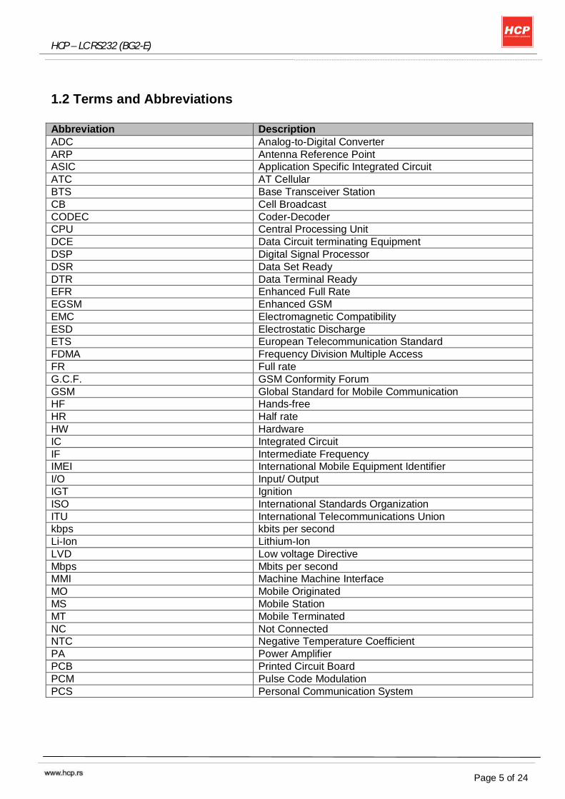
1.2 Terms and Abbreviations
Abbreviation Description ADC Analog-to-Digital Converter ARP Antenna Reference Point ASIC Application Specific Integrated Circuit ATC AT Cellular BTS Base Transceiver Station CB Cell Broadcast CODEC Coder-Decoder CPU Central Processing Unit DCE Data Circuit terminating Equipment DSP Digital Signal Processor DSR Data Set Ready DTR Data Terminal Ready EFR Enhanced Full Rate EGSM Enhanced GSM EMC Electromagnetic Compatibility ESD Electrostatic Discharge ETS European Telecommunication Standard FDMA Frequency Division Multiple Access FR Full rate G.C.F. GSM Conformity Forum GSM Global Standard for Mobile Communication HF Hands-free HR Half rate HW Hardware IC Integrated Circuit IF Intermediate Frequency IMEI International Mobile Equipment Identifier I/O Input/ Output IGT Ignition ISO International Standards Organization ITU International Telecommunications Union kbps kbits per second Li-Ion Lithium-Ion LVD Low voltage Directive Mbps Mbits per second MMI Machine Machine Interface MO Mobile Originated MS Mobile Station MT Mobile Terminated NC Not Connected NTC Negative Temperature Coefficient PA Power Amplifier PCB Printed Circuit Board PCM Pulse Code Modulation PCS Personal Communication System
HCP – LC RS232 (BG2-E)
Page 6 of 24
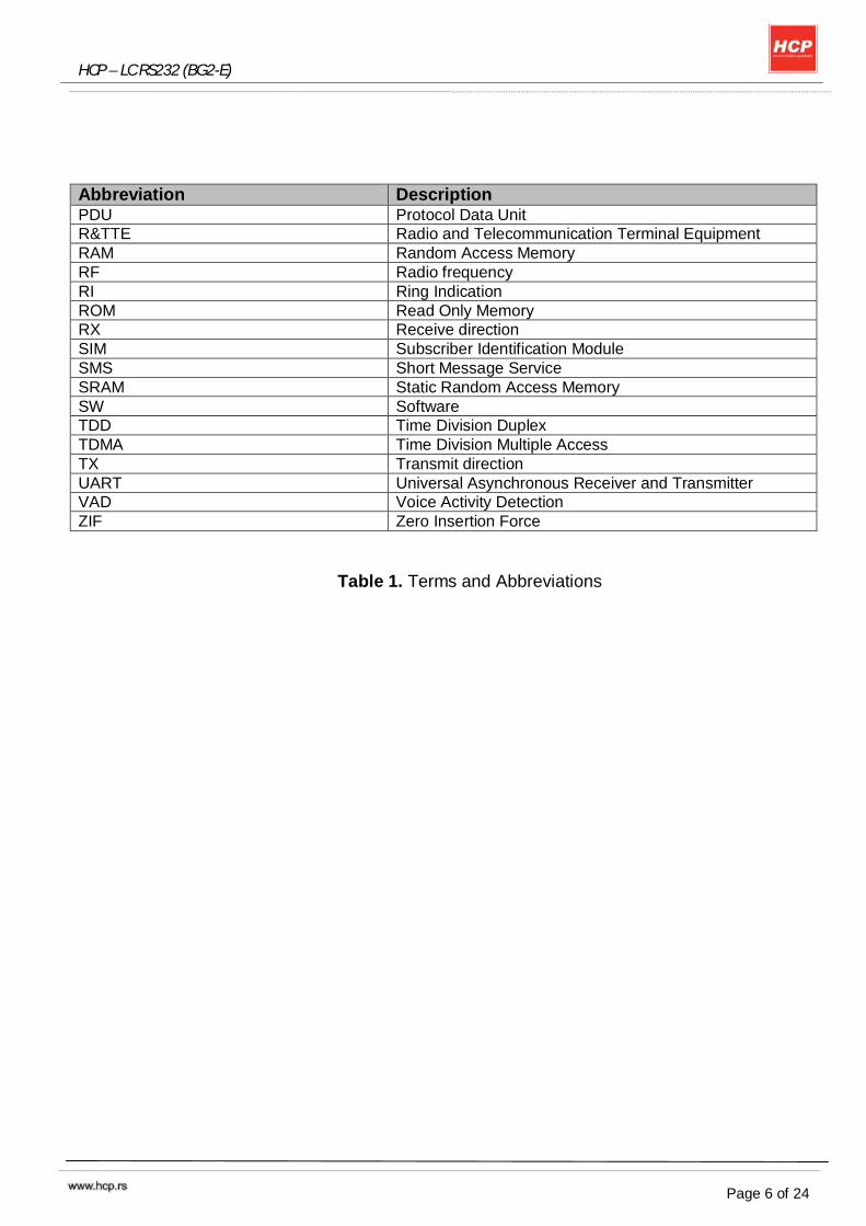
Abbreviation Description PDU Protocol Data Unit R&TTE Radio and Telecommunication Terminal Equipment RAM Random Access Memory RF Radio frequency RI Ring Indication ROM Read Only Memory RX Receive direction SIM Subscriber Identification Module SMS Short Message Service SRAM Static Random Access Memory SW Software TDD Time Division Duplex TDMA Time Division Multiple Access TX Transmit direction UART Universal Asynchronous Receiver and Transmitter VAD Voice Activity Detection ZIF Zero Insertion Force
Table 1. Terms and Abbreviations
HCP – LC RS232 (BG2-E)
Page 7 of 24
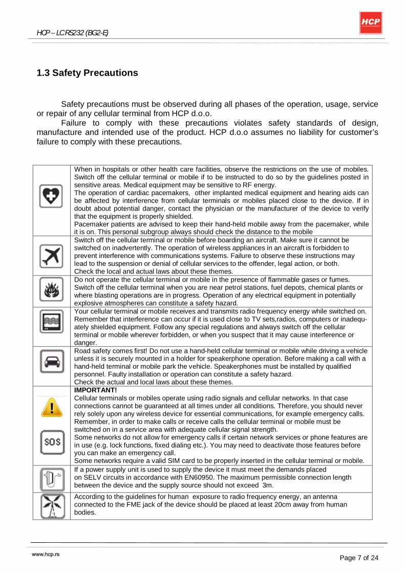
1.3 Safety Precautions
Safety precautions must be observed during all phases of the operation, usage, service or repair of any cellular terminal from HCP d.o.o.
Failure to comply with these precautions violates safety standards of design, manufacture and intended use of the product. HCP d.o.o assumes no liability for customer’s failure to comply with these precautions.
When in hospitals or other health care facilities, observe the restrictions on the use of mobiles. Switch off the cellular terminal or mobile if to be instructed to do so by the guidelines posted in sensitive areas. Medical equipment may be sensitive to RF energy. The operation of cardiac pacemakers, other implanted medical equipment and hearing aids can be affected by interference from cellular terminals or mobiles placed close to the device. If in doubt about potential danger, contact the physician or the manufacturer of the device to verify that the equipment is properly shielded. Pacemaker patients are advised to keep their hand-held mobile away from the pacemaker, while it is on. This personal subgroup always should check the distance to the mobile
Switch off the cellular terminal or mobile before boarding an aircraft. Make sure it cannot be switched on inadvertently. The operation of wireless appliances in an aircraft is forbidden to prevent interference with communications systems. Failure to observe these instructions may lead to the suspension or denial of cellular services to the offender, legal action, or both. Check the local and actual laws about these themes.
Do not operate the cellular terminal or mobile in the presence of flammable gases or fumes. Switch off the cellular terminal when you are near petrol stations, fuel depots, chemical plants or where blasting operations are in progress. Operation of any electrical equipment in potentially explosive atmospheres can constitute a safety hazard.
Your cellular terminal or mobile receives and transmits radio frequency energy while switched on. Remember that interference can occur if it is used close to TV sets,radios, computers or inadequ- ately shielded equipment. Follow any special regulations and always switch off the cellular terminal or mobile wherever forbidden, or when you suspect that it may cause interference or danger.
Road safety comes first! Do not use a hand-held cellular terminal or mobile while driving a vehicle unless it is securely mounted in a holder for speakerphone operation. Before making a call with a hand-held terminal or mobile park the vehicle. Speakerphones must be installed by qualified personnel. Faulty installation or operation can constitute a safety hazard. Check the actual and local laws about these themes.
IMPORTANT! Cellular terminals or mobiles operate using radio signals and cellular networks. In that case connections cannot be guaranteed at all times under all conditions. Therefore, you should never rely solely upon any wireless device for essential communications, for example emergency calls. Remember, in order to make calls or receive calls the cellular terminal or mobile must be switched on in a service area with adequate cellular signal strength. Some networks do not allow for emergency calls if certain network services or phone features are in use (e.g. lock functions, fixed dialing etc.). You may need to deactivate those features before you can make an emergency call. Some networks require a valid SIM card to be properly inserted in the cellular terminal or mobile.
If a power supply unit is used to supply the device it must meet the demands placed on SELV circuits in accordance with EN60950. The maximum permissible connection length between the device and the supply source should not exceed 3m.
According to the guidelines for human exposure to radio frequency energy, an antenna connected to the FME jack of the device should be placed at least 20cm away from human bodies.
HCP – LC RS232 (BG2-E)
Page 8 of 24
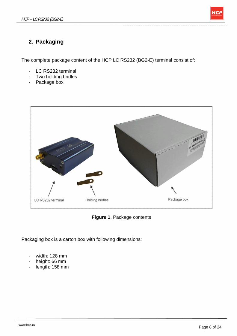
2. Packaging
The complete package content of the HCP LC RS232 (BG2-E) terminal consist of:
- LC RS232 terminal - Two holding bridles - Package box
Figure 1. Package contents Packaging box is a carton box with following dimensions:
- width: 128 mm - height: 66 mm - length: 158 mm
HCP – LC RS232 (BG2-E)
Page 9 of 24
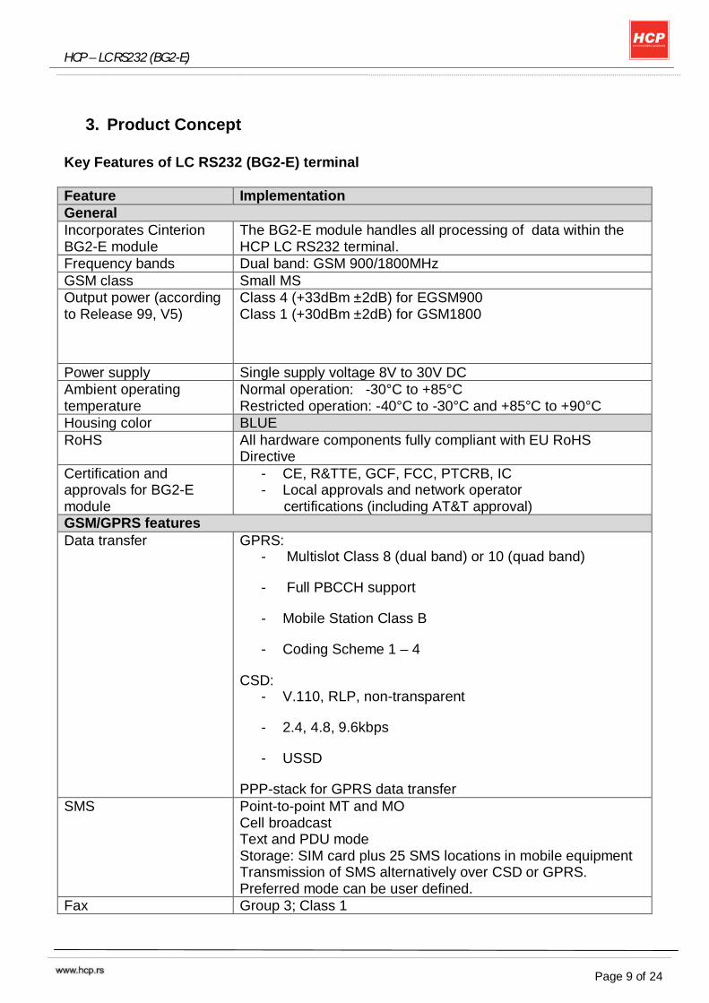
3. Product Concept
Key Features of LC RS232 (BG2-E) terminal
Feature Implementation General Incorporates Cinterion BG2-E module
The BG2-E module handles all processing of data within the HCP LC RS232 terminal.
Frequency bands Dual band: GSM 900/1800MHz GSM class Small MS Output power (according to Release 99, V5)
Class 4 (+33dBm ±2dB) for EGSM900 Class 1 (+30dBm ±2dB) for GSM1800
Power supply Single supply voltage 8V to 30V DC Ambient operating temperature
Normal operation: -30°C to +85°C Restricted operation: -40°C to -30°C and +85°C to +90°C
Housing color BLUE RoHS All hardware components fully compliant with EU RoHS
Directive Certification and approvals for BG2-E module
- CE, R&TTE, GCF, FCC, PTCRB, IC - Local approvals and network operator
certifications (including AT&T approval) GSM/GPRS features Data transfer GPRS:
- Multislot Class 8 (dual band) or 10 (quad band)
- Full PBCCH support
- Mobile Station Class B
- Coding Scheme 1 – 4
CSD: - V.110, RLP, non-transparent
- 2.4, 4.8, 9.6kbps
- USSD
PPP-stack for GPRS data transfer SMS Point-to-point MT and MO
Cell broadcast Text and PDU mode Storage: SIM card plus 25 SMS locations in mobile equipment Transmission of SMS alternatively over CSD or GPRS. Preferred mode can be user defined.
Fax Group 3; Class 1
HCP – LC RS232 (BG2-E)
Page 10 of 24
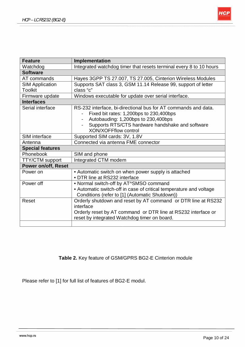
Feature Implementation Watchdog Integrated watchdog timer that resets terminal every 8 to 10 hours Software AT commands Hayes 3GPP TS 27.007, TS 27.005, Cinterion Wireless Modules SIM Application Toolkit
Supports SAT class 3, GSM 11.14 Release 99, support of letter class “c”
Firmware update Windows executable for update over serial interface. Interfaces Serial interface RS-232 interface, bi-directional bus for AT commands and data.
- Fixed bit rates: 1,200bps to 230,400bps - Autobauding: 1,200bps to 230,400bps - Supports RTS/CTS hardware handshake and software
XON/XOFFflow control SIM interface Supported SIM cards: 3V, 1.8V Antenna Connected via antenna FME connector Special features Phonebook SIM and phone TTY/CTM support Integrated CTM modem Power on/off, Reset Power on • Automatic switch on when power supply is attached
• DTR line at RS232 interface Power off • Normal switch-off by AT^SMSO command
• Automatic switch-off in case of critical temperature and voltage Conditions (refer to [1] (Automatic Shutdown))
Reset Orderly shutdown and reset by AT command or DTR line at RS232 interface Orderly reset by AT command or DTR line at RS232 interface or reset by integrated Watchdog timer on board.
Table 2. Key feature of GSM/GPRS BG2-E Cinterion module Please refer to [1] for full list of features of BG2-E modul.
HCP – LC RS232 (BG2-E)
Page 11 of 24
4. Interface Description
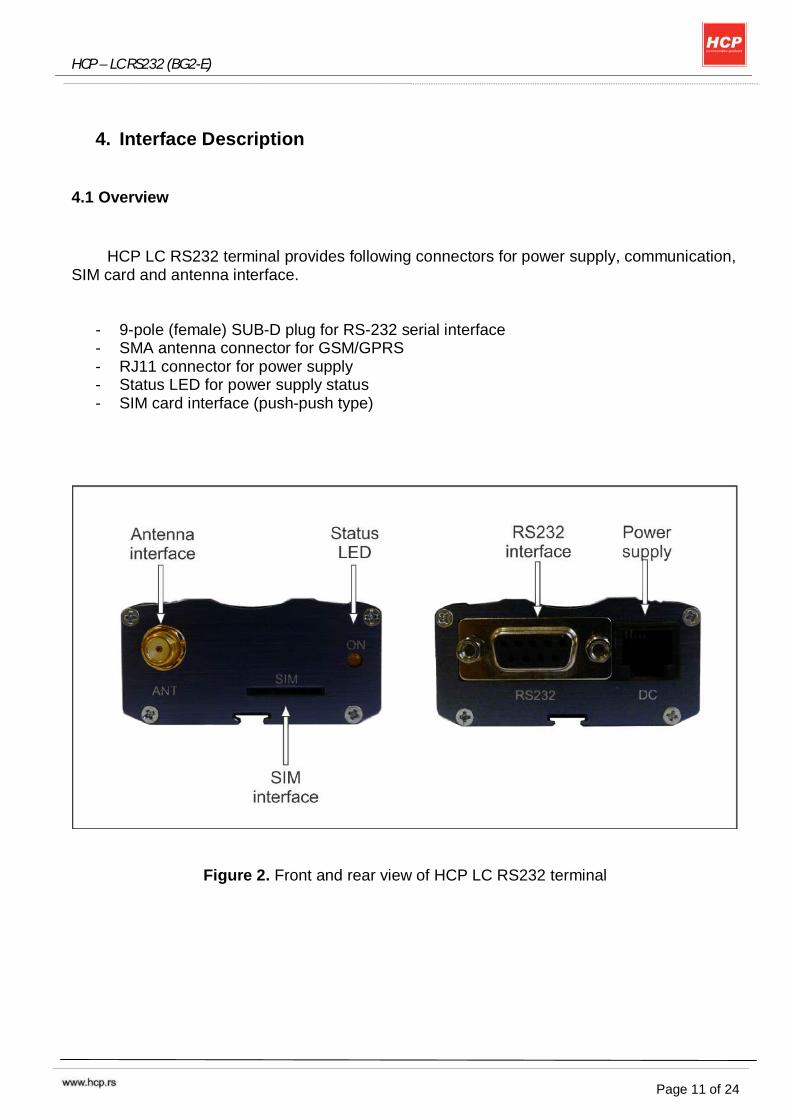
4.1 Overview
HCP LC RS232 terminal provides following connectors for power supply, communication, SIM card and antenna interface.
- 9-pole (female) SUB-D plug for RS-232 serial interface - SMA antenna connector for GSM/GPRS - RJ11 connector for power supply - Status LED for power supply status - SIM card interface (push-push type)
Figure 2. Front and rear view of HCP LC RS232 terminal
HCP – LC RS232 (BG2-E)
Page 12 of 24
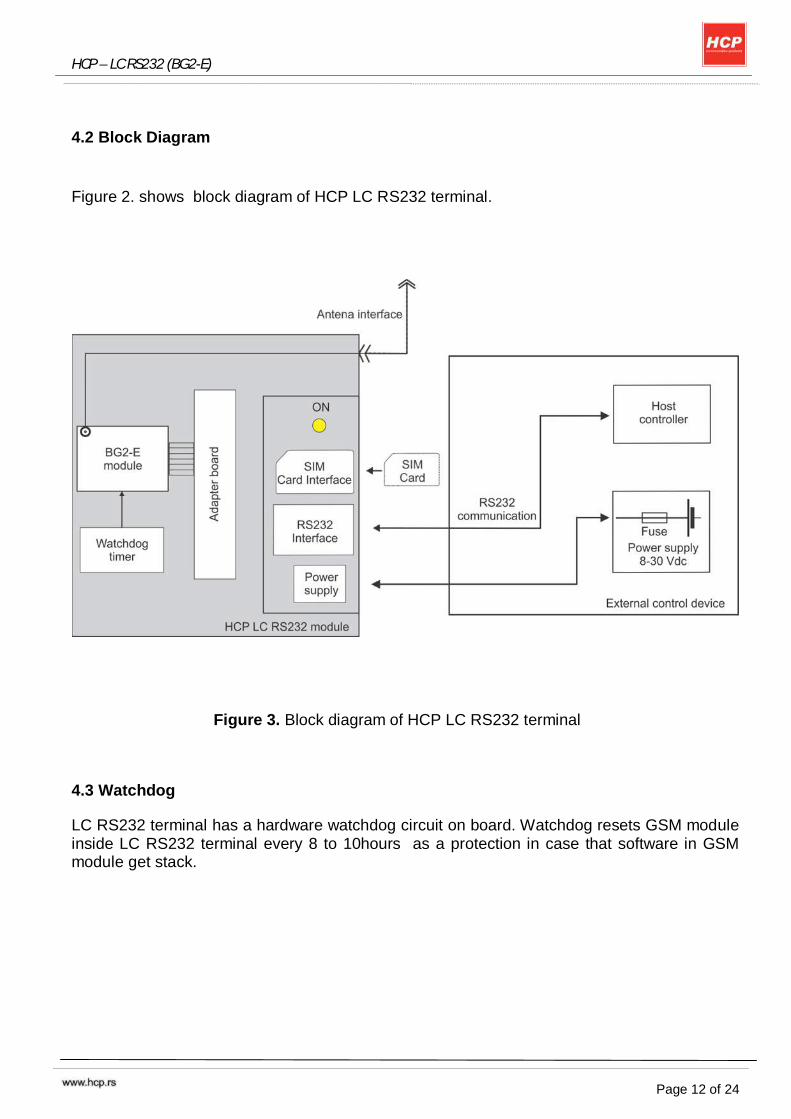
4.2 Block Diagram
Figure 2. shows block diagram of HCP LC RS232 terminal.
Figure 3. Block diagram of HCP LC RS232 terminal
4.3 Watchdog
LC RS232 terminal has a hardware watchdog circuit on board. Watchdog resets GSM module inside LC RS232 terminal every 8 to 10hours as a protection in case that software in GSM module get stack.
HCP – LC RS232 (BG2-E)
Page 13 of 24
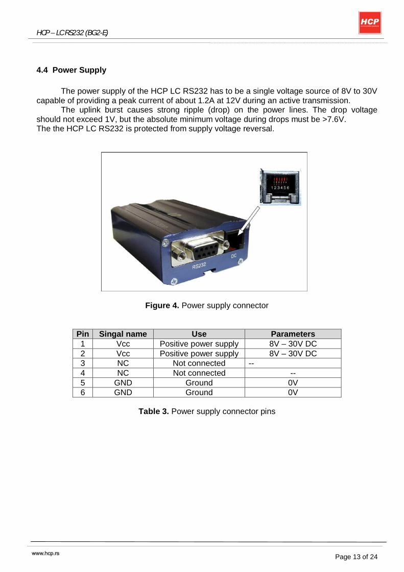
4.4 Power Supply
The power supply of the HCP LC RS232 has to be a single voltage source of 8V to 30V
capable of providing a peak current of about 1.2A at 12V during an active transmission. The uplink burst causes strong ripple (drop) on the power lines. The drop voltage
should not exceed 1V, but the absolute minimum voltage during drops must be >7.6V. The the HCP LC RS232 is protected from supply voltage reversal.
A
Figure 4. Power supply connector
Pin Singal name Use Parameters 1 Vcc Positive power supply 8V – 30V DC 2 Vcc Positive power supply 8V – 30V DC 3 NC Not connected -- 4 NC Not connected -- 5 GND Ground 0V 6 GND Ground 0V
Table 3. Power supply connector pins
HCP – LC RS232 (BG2-E)
Page 14 of 24
4.4.1 Turn LC RS232 terminal on
HCP LC RS232 terminal switches on automaticly when power supply is attached. After
start-up, the GSM module enters the net searching state. After startup of the GSM module the RS232 lines are in an undefined state for approx.
900ms. This may cause undefined characters to be transmitted over the RS232 lines during this period.
4.4.2 Reset LC RS232 terminal
One way to reset LC RS232 terminal is entering AT command AT+CFUN=x,1. For
details on AT+CFUN please see [1], [2]. Other ways for restarting LC RS232 terminal is:
- activating the DTR line on RS232 interface
- automatically by integrated watchdog timer on every 8 to 10 hours.
4.4.3 Turn off LC RS232 terminal
Normal shutdown:
- To turn off the LC RS232 Terminal use the AT^SMSO command, rather than disconnecting the power supply adapter.
This procedure lets the LC RS232 terminal GSM modul log off from the network and allows the software to enter a secure state and save data before disconnecting the power supply. After AT^SMSO has been entered the GSM modul returns the following result codes: ^SMSO: MS OFF OK ^SHUTDOWN
The "^SHUTDOWN" result code indicates that the GSM modul turns off in less than 1 second. After the shutdown procedure is complete the GSM modul enters the POWER DOWN mode.
4.4.4 Disconnecting power supply
Before disconnecting the power supply from the Vcc pin, make sure that the LC RS232
terminal is in a safe condition. The best way is to wait 5s after the "^SHUTDOWN" result code has been indicated.
HCP – LC RS232 (BG2-E)
Page 15 of 24
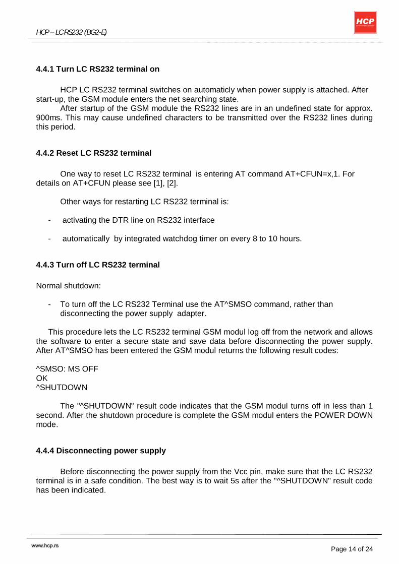
4.5 RS-232 Interface
Over RS232 interface, external device, PC or other control device with RS232 interface,
communicate with HCP LC RS232 terminal.
Figure 5. RS232 interface pin assignment
Pin Singal name Input/Output Function 1 DCD output Data Carrier Detect 2 RxD output Receive Data 3 TxD input Transmit Data 4 DTR input Data Terminal Ready 5 GND -- Ground 6 DSR output Data Set Ready 7 RTS input Request To Send 8 CTS output Clear To Send 9 RING output Ring Indication
Table 4. RS232 pin assignment
The RS-232 interface is implemented as a serial asynchronous transmitter and receiver
conforming to ITU-T V.24 Interchange Circuits DCE. Features:
- Primarily designed for controlling voice calls, transferring CSD, fax and GPRS data and for controlling the GSM module with AT commands.
- The DTR signal will only be polled once per second from the internal firmware of BG2-E - The RING signal serves to indicate incoming calls and other types of URCs (Unsolicited
Result Code). It can also be used to send pulses to the host application, for example to wake up the application from power saving state. See [2] for details on how to configure the RING line by AT^SCFG.
- Configured for 8 data bits, no parity and 1 stop bit. - can be operated at fixed bit rates from 1,200 bps to 230,400 bps. - Autobauding supports bit rates from 1,200 bps to 230,400 bps. - Supports RTS/CTS hardware flow control and XON/XOFF software flow control.
HCP – LC RS232 (BG2-E)
Page 16 of 24
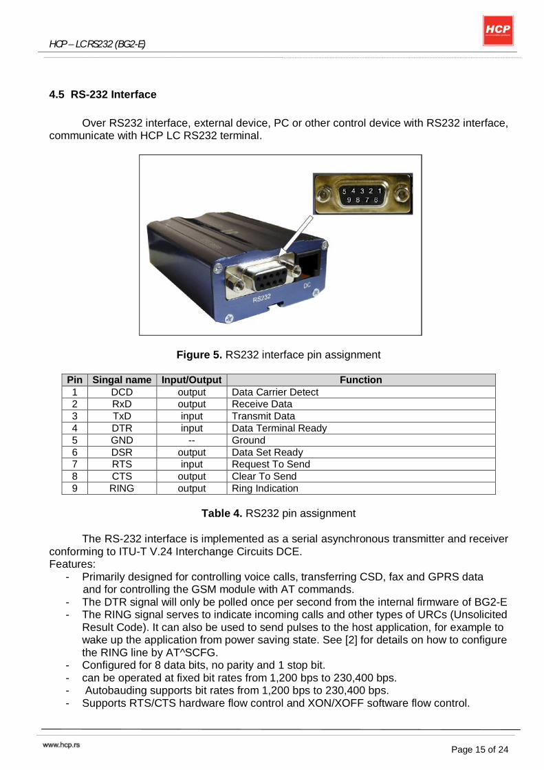
4.6 SIM interface
LC RS232 terminal provides SIM interface with automatic detection for 1.8V and 3V
SIM cards.
Figure 6. SIM interface
Removing and inserting the SIM card during operation requires the software to be reinitialized. Therefore, after reinserting the SIM card it is necessary to restart HCP LC RS232 terminal. Recommended procedure when inserting SIM card is to first switch off LC RS232 terminal and then put SIM card in SIM card holder. Note: No guarantee can be given, nor any liability accepted, if loss of data is encountered after removing the SIM card during operation. Also, no guarantee can be given for properly initializing any SIM card that the user inserts after having removed a SIM card during ope-ration. In this case, the application must restart the GSM module in HCP LC RS232.
HCP – LC RS232 (BG2-E)
Page 17 of 24
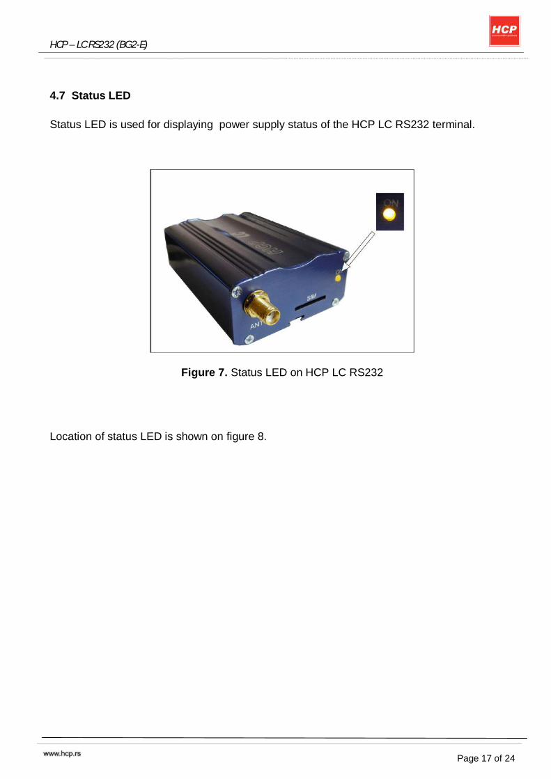
4.7 Status LED
Status LED is used for displaying power supply status of the HCP LC RS232 terminal.
Figure 7. Status LED on HCP LC RS232
Location of status LED is shown on figure 8.
HCP – LC RS232 (BG2-E)
Page 18 of 24
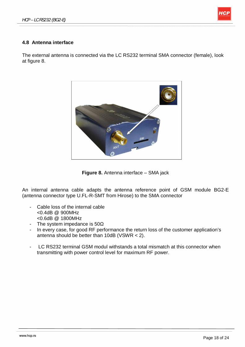
4.8 Antenna interface
The external antenna is connected via the LC RS232 terminal SMA connector (female), look at figure 8.
Figure 8. Antenna interface – SMA jack
An internal antenna cable adapts the antenna reference point of GSM module BG2-E (antenna connector type U.FL-R-SMT from Hirose) to the SMA connector
- Cable loss of the internal cable <0.4dB @ 900MHz <0.6dB @ 1800MHz
- The system impedance is 50Ω - In every case, for good RF performance the return loss of the customer application’s
antenna should be better than 10dB (VSWR < 2).
- LC RS232 terminal GSM modul withstands a total mismatch at this connector when transmitting with power control level for maximum RF power.
HCP – LC RS232 (BG2-E)
Page 19 of 24
5. Electrical and Environmental Characteristics
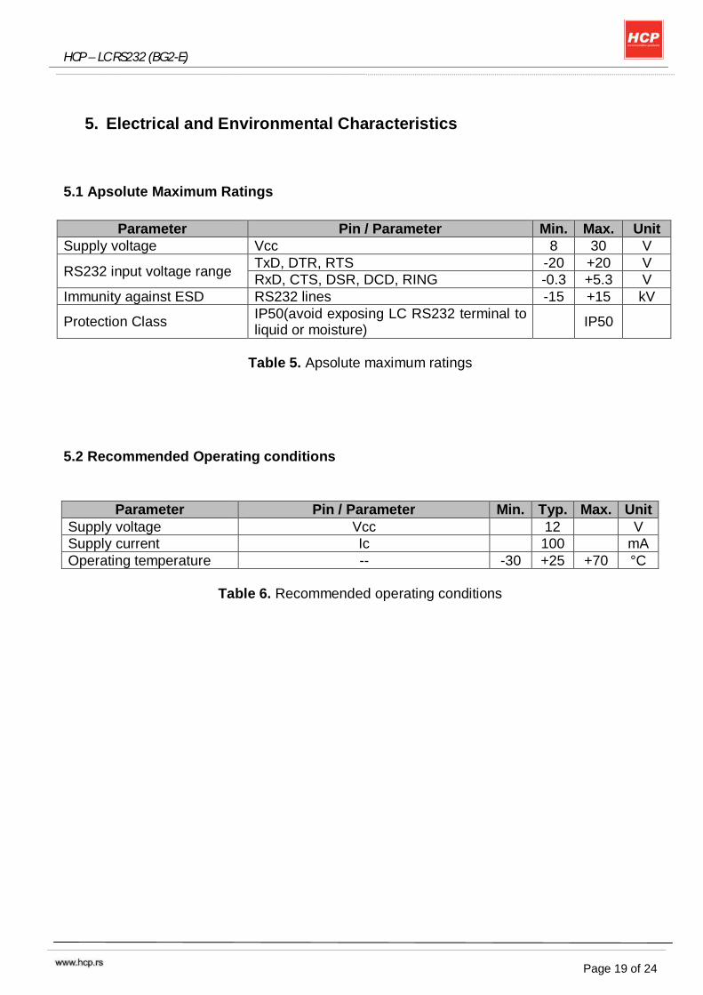
5.1 Apsolute Maximum Ratings
Parameter Pin / Parameter Min. Max. Unit
Supply voltage Vcc 8 30 V
RS232 input voltage range TxD, DTR, RTS -20 +20 V RxD, CTS, DSR, DCD, RING -0.3 +5.3 V
Immunity against ESD RS232 lines -15 +15 kV
Protection Class IP50(avoid exposing LC RS232 terminal to liquid or moisture)
IP50
Table 5. Apsolute maximum ratings
5.2 Recommended Operating conditions
Parameter Pin / Parameter Min. Typ. Max. Unit Supply voltage Vcc 12 V Supply current Ic 100 mA Operating temperature -- -30 +25 +70 °C
Table 6. Recommended operating conditions
HCP – LC RS232 (BG2-E)
Page 20 of 24
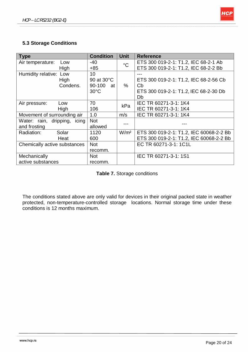
5.3 Storage Conditions
Type Condition Unit Reference Air temperature: Low High
-40 +85
°C ETS 300 019-2-1: T1.2, IEC 68-2-1 Ab ETS 300 019-2-1: T1.2, IEC 68-2-2 Bb
Humidity relative: Low High Condens.
10 90 at 30°C 90-100 at 30°C
%
--- ETS 300 019-2-1: T1.2, IEC 68-2-56 Cb Cb ETS 300 019-2-1: T1.2, IEC 68-2-30 Db Db
Air pressure: Low High
70 106
kPa IEC TR 60271-3-1: 1K4 IEC TR 60271-3-1: 1K4
Movement of surrounding air 1.0 m/s IEC TR 60271-3-1: 1K4 Water: rain, dripping, icing and frosting
Not allowed
--- ---
Radiation: Solar Heat
1120 600
W/m² ETS 300 019-2-1: T1.2, IEC 60068-2-2 Bb ETS 300 019-2-1: T1.2, IEC 60068-2-2 Bb
Chemically active substances Not recomm.
EC TR 60271-3-1: 1C1L
Mechanically active substances
Not recomm.
IEC TR 60271-3-1: 1S1
Table 7. Storage conditions
The conditions stated above are only valid for devices in their original packed state in weather protected, non-temperature-controlled storage locations. Normal storage time under these conditions is 12 months maximum.
HCP – LC RS232 (BG2-E)
Page 21 of 24
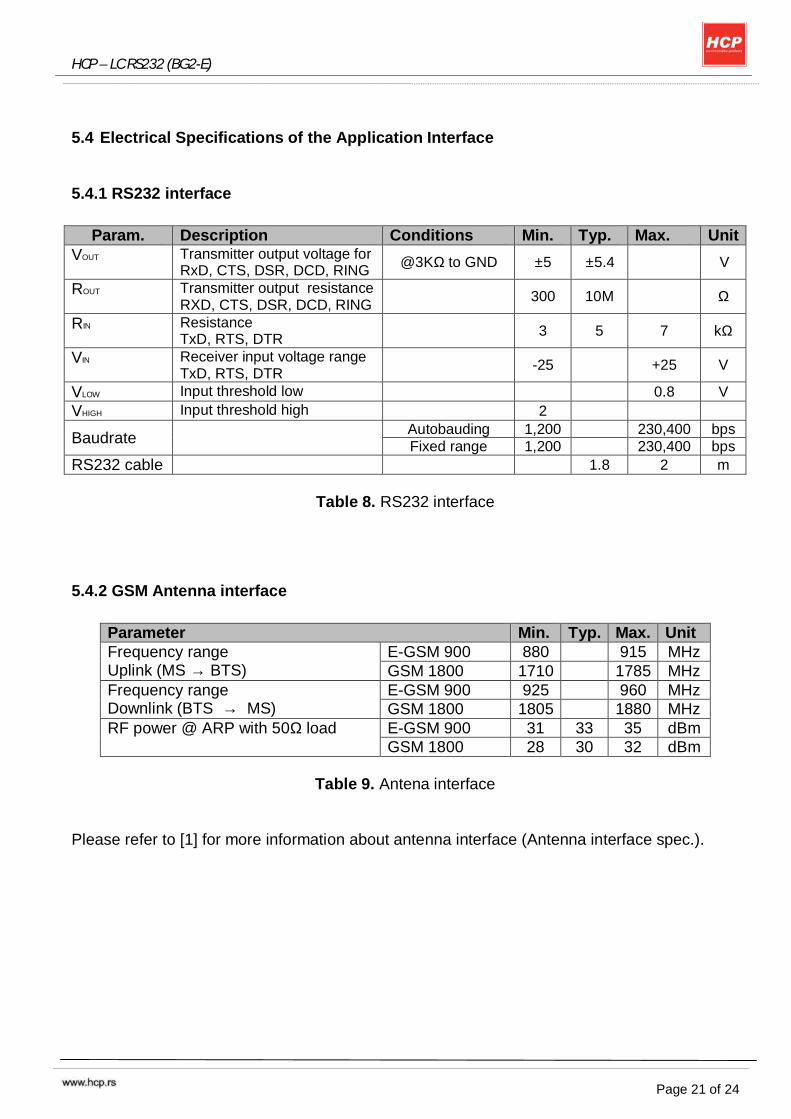
5.4 Electrical Specifications of the Application Interface
5.4.1 RS232 interface
Param. Description Conditions Min. Typ. Max. Unit
VOUT Transmitter output voltage for RxD, CTS, DSR, DCD, RING @3KΩ to GND ±5 ±5.4 V
ROUT Transmitter output resistance RXD, CTS, DSR, DCD, RING
300 10M Ω
RIN Resistance TxD, RTS, DTR
3 5 7 kΩ
VIN Receiver input voltage range TxD, RTS, DTR
-25 +25 V
VLOW Input threshold low 0.8 V VHIGH Input threshold high 2
Baudrate Autobauding 1,200 230,400 bps
Fixed range 1,200 230,400 bps RS232 cable 1.8 2 m
Table 8. RS232 interface
5.4.2 GSM Antenna interface
Parameter Min. Typ. Max. Unit Frequency range Uplink (MS → BTS)
E-GSM 900 880 915 MHz GSM 1800 1710 1785 MHz
Frequency range Downlink (BTS → MS)
E-GSM 900 925 960 MHz GSM 1800 1805 1880 MHz
RF power @ ARP with 50Ω load E-GSM 900 31 33 35 dBm GSM 1800 28 30 32 dBm
Table 9. Antena interface
Please refer to [1] for more information about antenna interface (Antenna interface spec.).
HCP – LC RS232 (BG2-E)
Page 22 of 24
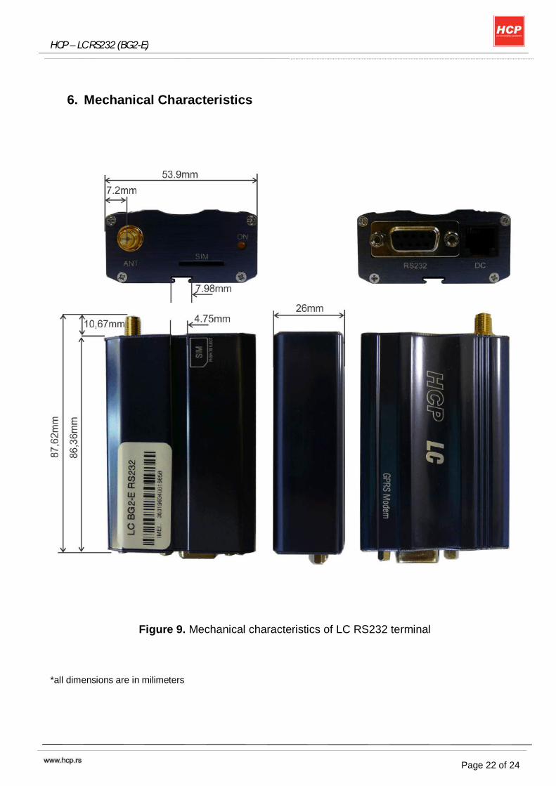
6. Mechanical Characteristics
Figure 9. Mechanical characteristics of LC RS232 terminal
*all dimensions are in milimeters
HCP – LC RS232 (BG2-E)
Page 23 of 24
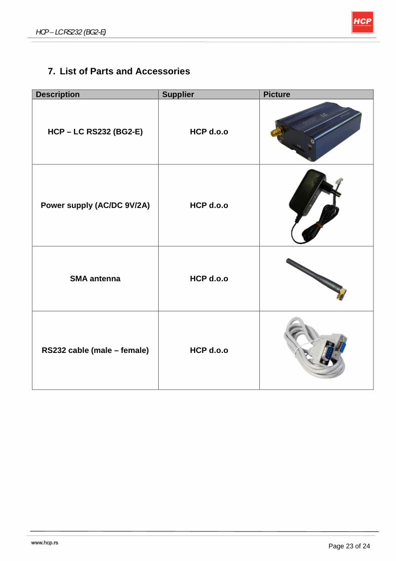
7. List of Parts and Accessories
Description Supplier Picture
HCP – LC RS232 (BG2-E) HCP d.o.o
Power supply (AC/DC 9V/2A) HCP d.o.o
SMA antenna HCP d.o.o
RS232 cable (male – female) HCP d.o.o
HCP – LC RS232 (BG2-E)
Page 24 of 24
HCP d.o.o. Mirka Tomica – pasaz 37000 Krusevac SERBIA
Phn. +381.37.445.401
+381.37.418.790 Fax. +381.37.448.351 Website www.hcp.rs
Sales email: [email protected]
Support: [email protected]
Development: [email protected]