HC/HC3 Centrifuge Settings Change Procedure Product...Yaskawa V1000 Variable Frequency Drive (VFD)...
6
CONFIDENTIAL Microseparator ® Coolant Management Systems bazell technologies ® www.bazell.com +1 925.603.0900 Service Bulletin SB00024 Rev B Approvals Engineering Paul H Dick 11/7/2014 Manufacturing Chris Bazell 11/7/2014 Name Signature Date HC/HC3 Centrifuge Settings Change Procedure
Transcript of HC/HC3 Centrifuge Settings Change Procedure Product...Yaskawa V1000 Variable Frequency Drive (VFD)...
CONFIDENTIAL
Microseparator® Coolant Management Systems
bazell technologies® www.bazell.com +1 925.603.0900
Service BulletinSB00024 Rev B
Approvals
Engineering Paul H Dick 11/7/2014
Manufacturing Chris Bazell 11/7/2014
Name Signature Date
HC/HC3 Centrifuge Settings Change Procedure

HC_HC3 Centrifuge Acceleration Setting Configuration Procedure
2 / 6 SB00024_B
Background: Over time the bearing purge annulus inside the centrifuge rotor assembly can accumulate debris inside that area resulting in Centrifuge VFD overloads. This is especially true on systems running high amounts of CR 39 lenses and/or have experienced significant foaming in the coolant tank at one time or another. This procedure can help prevent this from happening and/or alleviate the overload condition until such time as the centrifuge rotor can be removed and either cleaned or swapped with a rebuilt one from the factory. This procedure outlines how to increase the air pressure to the bearing annulus purge air regulator and changing of the centrifuge acceleration and feed cycle delay timer settings. We highly recommend using Satisloh LH 305 Plus Coolant and Super LOHFoam - 10 Defoamer on Bazell systems. Please review / request Bazell Service Bulletin SB00010 for more information.
HC_HC3 Centrifuge Acceleration Setting Configuration Procedure
3 / 6 SB00024_B
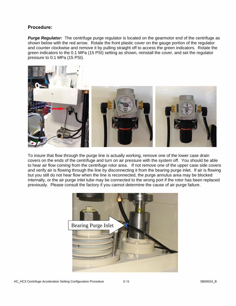
Procedure: Purge Regulator: The centrifuge purge regulator is located on the gearmotor end of the centrifuge as shown below with the red arrow. Rotate the front plastic cover on the gauge portion of the regulator and counter clockwise and remove it by pulling straight off to access the green indicators. Rotate the green indicators to the 0.1 MPa (15 PSI) setting as shown, reinstall the cover, and set the regulator pressure to 0.1 MPa (15 PSI).
To insure that flow through the purge line is actually working, remove one of the lower case drain covers on the ends of the centrifuge and turn on air pressure with the system off. You should be able to hear air flow coming from the centrifuge rotor area. If not remove one of the upper case side covers and verify air is flowing through the line by disconnecting it from the bearing purge inlet. If air is flowing but you still do not hear flow when the line is reconnected, the purge annulus area may be blocked internally, or the air purge inlet tube may be connected to the wrong port if the rotor has been replaced previously. Please consult the factory if you cannot determine the cause of air purge failure.
Bearing Purge Inlet
HC_HC3 Centrifuge Acceleration Setting Configuration Procedure
4 / 6 SB00024_B
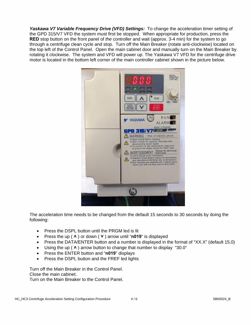
Yaskawa V7 Variable Frequency Drive (VFD) Settings: To change the acceleration timer setting of the GPD 315/V7 VFD the system must first be stopped. When appropriate for production, press the RED stop button on the front panel of the controller and wait (approx. 3-4 min) for the system to go through a centrifuge clean cycle and stop. Turn off the Main Breaker (rotate anti-clockwise) located on the top left of the Control Panel. Open the main cabinet door and manually turn on the Main Breaker by rotating it clockwise. The system and VFD will power up. The Yaskawa V7 VFD for the centrifuge drive motor is located in the bottom left corner of the main controller cabinet shown in the picture below.
The acceleration time needs to be changed from the default 15 seconds to 30 seconds by doing the following:
Press the DSPL button until the PRGM led is lit Press the up ( ˄ ) or down ( ˅ ) arrow until “n019” is displayed Press the DATA/ENTER button and a number is displayed in the format of “XX.X” (default 15.0) Using the up ( ˄ ) arrow button to change that number to display “30.0” Press the ENTER button and “n019” displays Press the DSPL button and the FREF led lights
Turn off the Main Breaker in the Control Panel. Close the main cabinet. Turn on the Main Breaker to the Control Panel.

HC_HC3 Centrifuge Acceleration Setting Configuration Procedure
5 / 6 SB00024_B
Yaskawa V1000 Variable Frequency Drive (VFD) Settings: To change the acceleration timer setting of the V1000 VFD the system must first be stopped. When appropriate for production, press the RED stop button on the front panel of the controller and wait (approx. 3-4 min) for the system to go through a centrifuge clean cycle and stop. Turn off the Main Breaker (rotate anti-clockwise) located on the top left of the Control Panel. Open the main cabinet door and manually turn on the Main Breaker by rotating it clockwise. The system and VFD will power up. The Yaskawa V1000 VFD for the centrifuge drive motor is located in the bottom left corner of the main controller cabinet as shown in the picture below.
The acceleration time needs to be changed from the default 15 seconds to 30 seconds by doing the following:
Press the up arrow button ( ˄ ) until “STUP” is displayed Press the ENTER button and “AAPL” will display Press the up arrow until “C1-01” is displayed Press the ENTER and a number is displayed in the format of “XXXX.X” (default 0015.0) Using the RESET ( ˃ / reset ) and up arrow ( ˄ ) or down arrow ( ˅ ) buttons to change that
number to display “0030.0” Press the ENTER button and “END” briefly displays then “C1-01” again Press the ESC button 3 or 4 times until the main page displays again
Turn off the Main Breaker in the Control Panel. Close the main cabinet. Turn on the Main Breaker to the Control Panel.

HC_HC3 Centrifuge Acceleration Setting Configuration Procedure
6 / 6 SB00024_B
Main Panel Feed Delay Settings: The FEED CYCLE delay timer needs to be set from the default 15 seconds to 30 seconds to correspond to the new Centrifuge acceleration time setting. Using the Control Panel display as shown below, do the following:
Press the “OTHER TIMERS” button Using the number pad enter the security password “5066” Press the “1 / CLEAN” button on the number pad Press the “OTHER TIMERS” button until “FEED DELAY” is displayed The setting will be displayed in seconds (default 15) To change the timer setting press the “CLEAR” button then enter the new value of “30” then
press the “ENTER” button to set the new value Press the “MICRO SEPERATOR” button to return to the main screen
Press the Green “START” button on the front panel to restart the system.