HB/MHB Series Hysteresis Brakes/Matched ... - magtrol.com · HB-3500 --- 1.36 x 10⁻¹ 19.30 26.00 26...
13
www.magtrol.com DATASHEET Page 1 / 13 © 2018 MAGTROL | Due to continual product development, Magtrol reserves the right to modify specifications without forewarning. HB/MHB SERIES HB/MHB SERIES HYSTERESIS BRAKES/MATCHED HYSTERESIS BRAKES FEATURES ▪ Ideal for low-torque/high-speed applications with exceptional power ratings ▪ Torque up to 3,500 oz·in/26 N·m ▪ Speed: up to 20,000 rpm ▪ Power: up to 2,400 W ▪ Available in Metric or English dimensions ▪ Torque independent of speed ▪ Long, maintenance-free life ▪ Magtrol hysteresis braking technology provides precise torque control independent of shaft speed ▪ EMC conforms to European standards Fig.1 : HB Series Hysteresis Brake DESCRITPTION Magtrol pioneered the technology of applying the principles of hysteresis to meet the critical needs for reliable, smooth and adjustable torque control. Magtrol’s Hysteresis Brakes produce torque strictly through a magnetic air gap without the use of magnetic particles or friction components. This method of braking provides far superior operating characteristics (smoother torque, longer life, superior repeatability, high degree of controllability, and less maintenance and down time) which make them the preferred choice for precise tension control during the processing of nearly any material, web or strand. MATCHED BRAKES In tension control applications that have multiple webs or multiple strands, it is very desirable to match the tension of each web or strand. This is most commonly attained by using a closed-loop servo control system which controls current to a braking device through the use of dancer arms, follower arms and in-line tension transducers. The problem with such systems is that each web or strand must be individually controlled, increasing the cost and complicating the system with multiple sensors and power supplies. To solve this problem, Magtrol developed a system to assure that every brake of a given model designation will be matched—at a predetermined torque and current point—to other brakes of the same model designation. Regardless of material and manufacturing tolerances, each brake is matched at the selected match point to within a tolerance of ±1%. The maximum deviation in torque from brake to brake at any point along their torque/ current curve (from 0 torque up to the selected matched torque point) is less than ±4%* of the selected matched torque value. With this level of matching, a system with multiple tension rollers would provide tension consistency within ±1% if set at the matched point with all brakes receiving the same current. The matched point can be any value between 50% and 100% of rated torque, which allows the brakes to be optimized for specific applications. Unless otherwise specified, all brakes are matched at 100 rpm. Brake Power Supply Transducer Brake Brake Brake Brake Brake Power Supply Transducer Brake Power Supply Transducer Matched Brakes Regular Brakes Brake Power Supply Transducer APPLICATIONS ▪ Precise control of wire tension during wind, hook and cut operation of high-speed automated winding machines ▪ Frictionless, non-breakaway force for tensioning materials during slitting and many other material processing operations ▪ Load simulation applications for life testing on electric motors, actuators, small gas engines, gearboxes, and many other rotating devices and assemblies ▪ Open-loop control for maintaining precise tension during winding process in transformer and coil winding operations ▪ Holding of backdriving loads ▪ Ultimate tension control, regardless of control scheme– dancer roll, follower arm, photo or ultrasonic sensors ▪ Precise load control and programmed repeatability in fitness machines
Transcript of HB/MHB Series Hysteresis Brakes/Matched ... - magtrol.com · HB-3500 --- 1.36 x 10⁻¹ 19.30 26.00 26...
www.magtrol.comDATASHEETPage 1 / 13© 2018 MAGTROL | Due to continual product development, Magtrol reserves the right to modify specifications without forewarning.
HB/MHB SERIES
HB/MHB SERIESHYSTERESIS BRAKES/MATCHED HYSTERESIS BRAKESFEATURES
▪ Ideal for low-torque/high-speed applications with exceptional power ratings
▪ Torque up to 3,500 oz·in/26 N·m
▪ Speed: up to 20,000 rpm
▪ Power: up to 2,400 W
▪ Available in Metric or English dimensions
▪ Torque independent of speed
▪ Long, maintenance-free life
▪ Magtrol hysteresis braking technology provides precise torque control independent of shaft speed
▪ EMC conforms to European standards
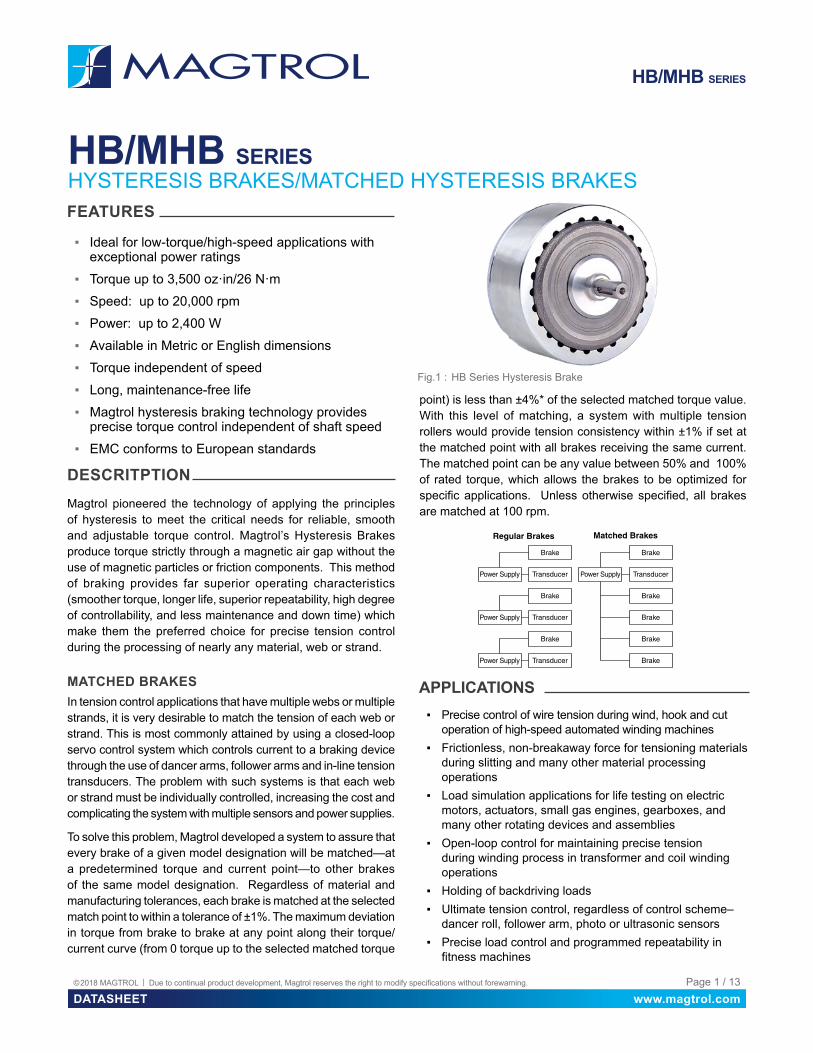
Fig.1 : HB Series Hysteresis Brake
DESCRITPTIONMagtrol pioneered the technology of applying the principles of hysteresis to meet the critical needs for reliable, smooth and adjustable torque control. Magtrol’s Hysteresis Brakes produce torque strictly through a magnetic air gap without the use of magnetic particles or friction components. This method of braking provides far superior operating characteristics (smoother torque, longer life, superior repeatability, high degree of controllability, and less maintenance and down time) which make them the preferred choice for precise tension control during the processing of nearly any material, web or strand.
MATCHED BRAKESIn tension control applications that have multiple webs or multiple strands, it is very desirable to match the tension of each web or strand. This is most commonly attained by using a closed-loop servo control system which controls current to a braking device through the use of dancer arms, follower arms and in-line tension transducers. The problem with such systems is that each web or strand must be individually controlled, increasing the cost and complicating the system with multiple sensors and power supplies.
To solve this problem, Magtrol developed a system to assure that every brake of a given model designation will be matched—at a predetermined torque and current point—to other brakes of the same model designation. Regardless of material and manufacturing tolerances, each brake is matched at the selected match point to within a tolerance of ±1%. The maximum deviation in torque from brake to brake at any point along their torque/current curve (from 0 torque up to the selected matched torque
point) is less than ±4%* of the selected matched torque value. With this level of matching, a system with multiple tension rollers would provide tension consistency within ±1% if set at the matched point with all brakes receiving the same current. The matched point can be any value between 50% and 100% of rated torque, which allows the brakes to be optimized for specific applications. Unless otherwise specified, all brakes are matched at 100 rpm.
Brake
Power Supply Transducer
Brake
Brake
Brake
Brake
Brake
Power Supply Transducer
Brake
Power Supply Transducer
Matched BrakesRegular Brakes
Brake
Power Supply Transducer
APPLICATIONS ▪ Precise control of wire tension during wind, hook and cut
operation of high-speed automated winding machines ▪ Frictionless, non-breakaway force for tensioning materials
during slitting and many other material processing operations
▪ Load simulation applications for life testing on electric motors, actuators, small gas engines, gearboxes, and many other rotating devices and assemblies
▪ Open-loop control for maintaining precise tension during winding process in transformer and coil winding operations
▪ Holding of backdriving loads ▪ Ultimate tension control, regardless of control scheme–
dancer roll, follower arm, photo or ultrasonic sensors ▪ Precise load control and programmed repeatability in
fitness machines
www.magtrol.comDATASHEETPage 2 / 13© 2018 MAGTROL | Due to continual product development, Magtrol reserves the right to modify specifications without forewarning.
HB/MHB SERIES
LONG, MAINTENANCE-FREE LIFEMagtrol Hysteresis Brakes produce torque strictly through a magnetic air gap, making them distinctly different from mechanical-friction and magnetic particle devices. Because hysteresis devices do not depend on friction or shear forces to produce torque, they do not suffer the problems of wear, particle aging, and seal leakage. As a result, hysteresis devices typically have life expectancies many times that of friction and magnetic particle devices.
LIFE CYCLE COST ADVANTAGESWhile the initial cost of hysteresis devices may be the same or slightly more than that of their counterparts, the high cost of replacing, repairing and maintaining friction and magnetic particle devices often makes hysteresis devices the most cost-effective means of tension and torque control available.
EXCELLENT ENVIRONMENTAL STABILITYMagtrol hysteresis devices can withstand significant variation in temperature and other operating conditions. In addition, because they have no particles or contacting active parts, Hysteresis Brakes are extremely clean. Magtrol devices are used in food and drug packaging operations, in clean rooms, and environmental test chambers.
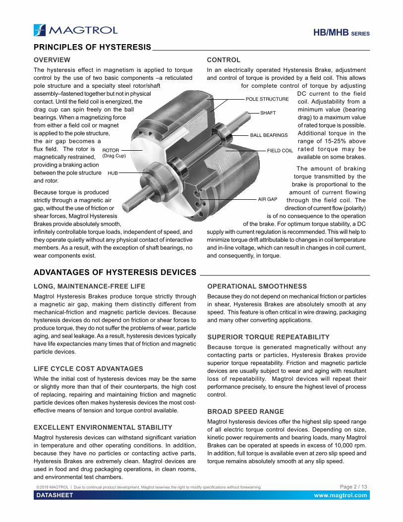
OVERVIEWThe hysteresis effect in magnetism is applied to torque control by the use of two basic components –a reticulated pole structure and a specialty steel rotor/shaft assembly–fastened together but not in physical contact. Until the field coil is energized, the drag cup can spin freely on the ball bearings. When a magnetizing force from either a field coil or magnet is applied to the pole structure, the air gap becomes a flux field. The rotor is magnetically restrained, providing a braking action between the pole structure and rotor.
Because torque is produced strictly through a magnetic air gap, without the use of friction or shear forces, Magtrol Hysteresis Brakes provide absolutely smooth, infinitely controllable torque loads, independent of speed, and they operate quietly without any physical contact of interactive members. As a result, with the exception of shaft bearings, no wear components exist.
CONTROLIn an electrically operated Hysteresis Brake, adjustment and control of torque is provided by a field coil. This allows
for complete control of torque by adjusting DC current to the field coil. Adjustability from a minimum value (bearing drag) to a maximum value of rated torque is possible. Additional torque in the range of 15-25% above rated torque may be available on some brakes.
The amount of braking torque transmitted by the
brake is proportional to the amount of current flowing
through the field coil. The direction of current flow (polarity)
is of no consequence to the operation of the brake. For optimum torque stability, a DC
supply with current regulation is recommended. This will help to minimize torque drift attributable to changes in coil temperature and in-line voltage, which can result in changes in coil current, and consequently, in torque.
AIR GAP
FIELD COIL
BALL BEARINGS
SHAFT
POLE STRUCTURE
HUB
ROTOR(Drag Cup)
OPERATIONAL SMOOTHNESSBecause they do not depend on mechanical friction or particles in shear, Hysteresis Brakes are absolutely smooth at any speed. This feature is often critical in wire drawing, packaging and many other converting applications.
SUPERIOR TORQUE REPEATABILITYBecause torque is generated magnetically without any contacting parts or particles, Hysteresis Brakes provide superior torque repeatability. Friction and magnetic particle devices are usually subject to wear and aging with resultant loss of repeatability. Magtrol devices will repeat their performance precisely, to ensure the highest level of process control.
BROAD SPEED RANGEMagtrol hysteresis devices offer the highest slip speed range of all electric torque control devices. Depending on size, kinetic power requirements and bearing loads, many Magtrol Brakes can be operated at speeds in excess of 10,000 rpm. In addition, full torque is available even at zero slip speed and torque remains absolutely smooth at any slip speed.
PRINCIPLES OF HYSTERESIS
ADVANTAGES OF HYSTERESIS DEVICES

www.magtrol.comDATASHEETPage 3 / 13© 2018 MAGTROL | Due to continual product development, Magtrol reserves the right to modify specifications without forewarning.
HB/MHB SERIES
SPECIFICATIONSHYSTERESIS BRAKE RATINGS - ENGLISH
BRAKE MODEL MATCHED BRAKE MODEL
MIN. TORQUE AT RATED CURRENT
RATED CURRENT
VOLTAGEa) MAXIMUM SPEED
KINETIC POWERb)
5 MINUTES CONTINUOUS
N·m oz·in mA VDC rpm W W
HB-2.5 MHB-2.5 0.018 2.5 146 25.0 20,000 20 5HB-10 MHB-10 0.071 10.0 133 24.0 20,000 45 12HB-16 --- 0.113 16.0 192 24.0 20,000 75 20HB-38 MHB-38 0.268 38.0 250 26.3 15,000 90 25HB-50 MHB-50 0.350 50.0 253 24.0 15,000 90 23
HB-140 MHB-140 1.000 140.0 253 24.0 12,000 300 75HB-250 MHB-250 1.750 250.0 270 26.0 10,000 450 110HB-450 MHB-450 3.200 450.0 442 22.1 8,000 670 160HB-750 MHB-750 5.300 750.0 383 23.0 7,000 1,000 200HB-840 --- 5.900 840.0 600 24.0 6,000 1,340 300HB-1750 MHB-1750 12.360 1,750.0 500 26.0 6,000 1,200 350HB-3500 --- 24.720 3,500.0 1,000 26.0 6,000 2,400 600
BRAKE MODEL MATCHED BRAKE MODEL
DRAG TORQUE DE-ENERGIZED
@ 1,000 rpm
NOMINAL POWER
RESISTANCE AT 25°C ± 10%
EXTERNAL INERTIA
WEIGHT
N·m oz·in W Ω kg·cm2 lb·in·s2 kg lb
HB-2.5 MHB-2.5 3.53 x 10⁻⁴ 0.05 3.70 171 4.30 x 10⁻³ 3.800 x 10⁻⁶ 0.11 0.24HB-10 MHB-10 7.06 x 10⁻⁴ 0.10 3.18 180 3.70 x 10⁻² 3.300 x 10⁻⁵ 0.22 0.49HB-16 --- 7.06 x 10⁻⁴ 0.10 4.60 125 6.30 x 10⁻² 5.600 x 10⁻⁵ 0.29 0.65HB-38 MHB-38 1.41 X 10⁻³ 0.20 6.60 105 0.97 X 10⁻¹ 8.600 x 10⁻⁵ 0.48 1.06HB-50 MHB-50 1.41 X 10⁻³ 0.20 6.10 95 1.67 X 10⁻¹ 1.478 x 10⁻⁴ 0.78 1.72
HB-140 MHB-140 4.94 x 10⁻³ 0.70 6.10 95 1.03 x 100 9.100 x 10⁻⁴ 1.86 4.10
HB-250 MHB-250 7.77 X 10⁻³ 1.10 7.00 96 3.11 x 100 2.750 x 10⁻³ 3.50 7.70
HB-450 MHB-450 1.41 x 10⁻² 2.00 9.80 50 7.50 x 100 6.600 x 10⁻³ 5.85 12.90HB-750 MHB-750 5.00 x 10⁻² 7.08 8.80 60 11.40 x 100 1.000 x 10⁻² 12.80 28.30HB-840 --- 2.82 X 10⁻² 4.00 14.40 40 14.80 x 100 1.310 x 10⁻² 12.00 26.30HB-1750 MHB-1750 9.18 x 10⁻² 13.00 13.00 52 5.63 x 101 4.980 x 10⁻² 24.50 54.00HB-3500 --- 1.36 x 10⁻¹ 19.30 26.00 26 1.11 x 10² 1.056 x 10⁻¹ 50.00 110.00
a) Other coil voltages are available.b) Kinetic power ratings are maximum values based on limiting coil and/or bearing temperature to approximately 100 ºC, and should not be exceeded. Actual
values in service may vary ±50% depending on mounting, ventilation, ambient temperature, etc.* Angular Acceleration values are available upon request** To prevent damage to the power supply from inductive kickback, connect a diode rated at greater than or equal to the power supply’s output voltage and current
across the brake leads. Connect the cathode to the positive lead and the anode to the negative lead.

www.magtrol.comDATASHEETPage 4 / 13© 2018 MAGTROL | Due to continual product development, Magtrol reserves the right to modify specifications without forewarning.
HB/MHB SERIES
DIMENSIONS
ØL Bore Circle
K (3) Mounting Holes - equally spaced IJ
F
H
MM
ØBØCØA
N N
ØB
D
G
E
HYSTERESIS BRAKE MODEL
MATCHED BRAKE MODEL
ØA ØB ØC D E F G H I J K ØL M N
--- MHB-2.5 1.250 0.1250 0.375 0.010 0.030 0.73 1.564 0.30 0.94 0.29 #4-40 ↧ 0.16 0.750 --- ---
HB-2.5 --- 1.250 0.1250 0.375 0.012 0.030 0.73 1.564 0.29 0.94 0.29 #4-40 ↧ 0.16 0.750 --- ---
HB-10 MHB-10 1.800 .01875 0.500 0.021 0.096 0.82 2.120 0.50 1.00 0.50 #4-40 ↧ 0.19 0.687 0.375 0.025
HB-16 --- 1.970 0.1875 0.500 0.015 0.096 0.81 2.109 0.50 0.95 0.50 #4-40 ↧ 0.25 0.750 0.375 0.025
HB-38 MHB-38 2.155 0.2500 0.625 0.032 0.096 1.25 3.000 0.56 1.69 0.63 #6-32 ↧ 0.25 0.906 0.375 0.025
HB-50 MHB-50 2.360 0.2500 0.625 0.033 0.096 1.56 3.000 0.56 1.69 0.63 #6-32 ↧ 0.25 0.906 0.375 0.025
HB-140 MHB-140 3.624 0.3750 0.875 0.025 0.140 1.53 3.968 1.00 2.00 0.80 #8-32 ↧ 0.37 1.500 0.625 0.060
HB-250 MHB-250 4.437 0.5000 1.125 0.035 0.156 1.98 4.718 1.06 2.53 0.93 #10-32 ↧ 0.50 1.750 0.625 0.060
HB-450 MHB-450 5.420 0.5000 1.125 0.035 0.156 2.06 5.156 1.06 2.87 1.03 #10-32 ↧ 0.38 1.750 0.630 0.060
HB-750 MHB-750 6.220 0.6250 1.375 0.035 0.163 2.87 6.930 1.50 3.74 1.50 ¼-20 ↧ 0.44 2.750 0.750 0.060HB-840 --- 5.485 0.5000 * * * 4.13 7.750 1.00 * 1.00 * * 0.625 0.060
HB-1750 MHB-1750 8.900 1.0000 2.000 0.055 0.250 3.00 8.310 2.04 4.18 1.79 ¼-20 ↧ 0.50 3.000
#807 woodruff keyway
(2 places)
HB-3500 --- 8.900 1.0000 * * * 6.00 12.460 2.04 * 2.04 * *
#807 woodruff keyway
(2 places)
* HB-840 and HB-3500 are double brake assemblies that require base mounting. See base mounting dimensions below for details. Magtrol manufactures double brakes to increase torque capability. For more information and a drawing, contact Magtrol.
BASE MOUNTING DIMENSIONSBase mounting is standard on all HB-840, HB-3500 and HB-3500M brakes.
FFGG HH
AAJJCC BB
DD
EEØKK (4)Thru Holes
MODEL AA BB CC DD EE FF GG HH JJ ØKK
English Dimensions:HB-840 4.13 0.25 3.63 0.50 3.15 5.25 4.75 0.25 1.81 0.204HB-3500 5.00 0.50 4.00 0.50 4.75 8.50 7.50 0.50 3.73 0.406Metric Dimensions:HB-3500M 127.0 13.5 100 12.7 120.7 216.0 190 13 92.5 11
HB/MHB SERIES ENGLISH DIMENSIONS (INCHES)

www.magtrol.comDATASHEETPage 5 / 13© 2018 MAGTROL | Due to continual product development, Magtrol reserves the right to modify specifications without forewarning.
HB/MHB SERIES
0.00
1.25
2.50
3.75
5.00
6.25
7.50
8.75
10.00
11.25
12.50
0 2,000 4,000 6,000 8,000 10,000 12,000 14,000 16,000 18,000 20,000
Torq
ue (o
z-in
)
Speed (rpm)
HB-10, Power Absorption Curve
Continuous 5-min HB-16 HB-38/MHB-38
0.00
2.00
4.00
6.00
8.00
10.00
12.00
14.00
16.00
18.00
20.00
0 2,000 4,000 6,000 8,000 10,000 12,000 14,000 16,000 18,000 20,000
Torq
ue (o
z-in
)
Speed (rpm)
HB-16, Power Absorption Curve
Continuous 5-min
SPECIFICATIONS
HB-2.5/MHB-2.5 HB-10/MHB-10
0.000
0.313
0.625
0.938
1.250
1.563
1.875
2.188
2.500
2.813
3.125
0 2,000 4,000 6,000 8,000 10,000 12,000 14,000 16,000 18,000 20,000
Torq
ue (o
z-in
)
Speed (rpm)
HB-2.5, Power Absorption Curve
Continuous 5-min
POWER ABSORPTION CURVES
HB-50/MHB-50 HB-140/MHB-140
0.00
4.75
9.50
14.25
19.00
23.75
28.50
33.25
38.00
42.75
47.50
0 1,500 3,000 4,500 6,000 7,500 9,000 10,500 12,000 13,500 15,000
Torq
ue (o
z-in
)
Speed (rpm)
HB-38, Power Absorption Curve
Continuous 5-min
0.00
6.25
12.50
18.75
25.00
31.25
37.50
43.75
50.00
56.25
62.50
0 1,500 3,000 4,500 6,000 7,500 9,000 10,500 12,000 13,500 15,000
Torq
ue (o
z-in
)
Speed (rpm)
HB-50, Power Absorption Curve
Continuous 5-min
0.00
17.50
35.00
52.50
70.00
87.50
105.00
122.50
140.00
157.50
175.00
0 1,200 2,400 3,600 4,800 6,000 7,200 8,400 9,600 10,800 12,000
Torq
ue (o
z-in
)
Speed (rpm)
HB-140, Power Absorption Curve
Continuous 5-min
www.magtrol.comDATASHEETPage 6 / 13© 2018 MAGTROL | Due to continual product development, Magtrol reserves the right to modify specifications without forewarning.
HB/MHB SERIES
SPECIFICATIONSHB-250/MHB-250 HB-450/MHB-450
0.00
31.25
62.50
93.75
125.00
156.25
187.50
218.75
250.00
281.25
312.50
0 1,000 2,000 3,000 4,000 5,000 6,000 7,000 8,000 9,000 10,000
Torq
ue (o
z-in
)
Speed (rpm)
HB-250, Power Absorption Curve
Continuous 5-min
0.00
56.25
112.50
168.75
225.00
281.25
337.50
393.75
450.00
506.25
562.50
0 800 1,600 2,400 3,200 4,000 4,800 5,600 6,400 7,200 8,000
Torq
ue (o
z-in
)
Speed (rpm)
HB-450, Power Absorption Curve
Continuous 5-min HB-750/MHB-750 HB-840
0.00
93.75
187.50
281.25
375.00
468.75
562.50
656.25
750.00
843.75
937.50
0 700 1,400 2,100 2,800 3,500 4,200 4,900 5,600 6,300 7,000
Torq
ue (o
z-in
)
Speed (rpm)
HB-750, Power Absorption Curve
Continuous 5-min
0.00
105.00
210.00
315.00
420.00
525.00
630.00
735.00
840.00
945.00
1050.00
0 600 1,200 1,800 2,400 3,000 3,600 4,200 4,800 5,400 6,000
Torq
ue (o
z-in
)
Speed (rpm)
HB-840, Power Absorption Curve
Continuous 5-min HB-1750/MHB-1750 HB-3500
0.00
218.75
437.50
656.25
875.00
1093.75
1312.50
1531.25
1750.00
1968.75
2187.50
0 600 1,200 1,800 2,400 3,000 3,600 4,200 4,800 5,400 6,000
Torq
ue (o
z-in
)
Speed (rpm)
HB-1750, Power Absorption Curve
Continuous 5-min
0.00
437.50
875.00
1312.50
1750.00
2187.50
2625.00
3062.50
3500.00
3937.50
4375.00
0 600 1,200 1,800 2,400 3,000 3,600 4,200 4,800 5,400 6,000
Torq
ue (o
z-in
)
Speed (rpm)
HB-3500, Power Absorption Curve
Continuous 5-min
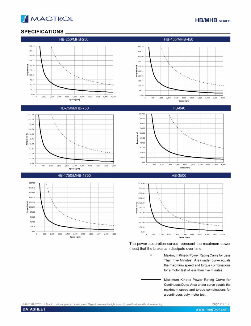
Maximum Kinetic Power Rating Curve for Continuous Duty: Area under curve equals the maximum speed and torque combinations for a continuous duty motor test.
Maximum Kinetic Power Rating Curve for Less Than Five Minutes: Area under curve equals the maximum speed and torque combinations for a motor test of less than five minutes.
The power absorption curves represent the maximum power (heat) that the brake can dissipate over time.
www.magtrol.comDATASHEETPage 7 / 13© 2018 MAGTROL | Due to continual product development, Magtrol reserves the right to modify specifications without forewarning.
HB/MHB SERIES
SPECIFICATIONS
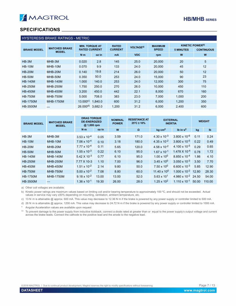
HYSTERESIS BRAKE RATINGS - METRIC
BRAKE MODEL MATCHED BRAKE MODEL
MIN. TORQUE AT RATED CURRENT
RATED CURRENT
VOLTAGEa) MAXIMUM SPEED
KINETIC POWERb)
5 MINUTES CONTINUOUS
N·m oz·in mA VDC rpm W W
HB-3M MHB-3M 0.020 2.8 145 25.0 20,000 20 5HB-10M MHB-10M 0.070 9.9 133 24.0 20,000 45 12
HB-20M MHB-20M 0.140 19.8 214 26.0 20,000 50 12HB-50M MHB-50M 0.350 50.0 253 24.0 15,000 90 23HB-140M MHB-140M 1.000 140.0 253 24.0 12,000 300 75HB-250M MHB-250M 1.750 250.0 270 26.0 10,000 450 110HB-450M MHB-450M 3.200 450.0 442 22.1 8,000 670 160HB-750M MHB-750M 5.000 708.0 383 23.0 7,000 1,000 200HB-1750M MHB-1750M 13.000c) 1,840.0 600 31.2 6,000 1,200 350HB-3500M --- 26.000d) 3,682.0 1,200 31.2 6,000 2,400 600
BRAKE MODEL MATCHED BRAKE MODEL
DRAG TORQUE DE-ENERGIZED
@ 1,000 rpm
NOMINAL POWER
RESISTANCE AT 25°C ± 10%
EXTERNAL INERTIA
WEIGHT
N·m oz·in W Ω kg·cm2 lb·in·s2 kg lb
HB-3M MHB-3M 3.53 x 10⁻⁴ 0.05 3.59 171.0 4.30 x 10⁻³ 3.800 x 10⁻⁶ 0.11 0.24HB-10M MHB-10M 7.06 x 10⁻⁴ 0.10 3.18 180.0 4.35 x 10⁻² 3.800 x 10⁻⁵ 0.22 0.49
HB-20M MHB-20M 7.77 x 10⁻⁴ 0.11 5.65 120.0 4.58 x 10⁻² 4.100 x 10⁻⁵ 0.29 0.65
HB-50M MHB-50M 1.55 x 10⁻³ 0.22 6.10 95.0 1.67 x 10⁻¹ 1.478 X 10⁻⁴ 0.78 1.72HB-140M MHB-140M 5.42 X 10⁻³ 0.77 6.10 95.0 1.00 x 100 8.850 x 10⁻⁴ 1.86 4.10HB-250M MHB-250M 7.77 X 10⁻³ 1.10 7.00 96.0 3.45 x 100 3.050 x 10⁻³ 3.50 7.70HB-450M MHB-450M 1.51 x 10⁻² 2.14 9.80 50.0 7.50 x 100 6.600 x 10⁻³ 5.85 12.90HB-750M MHB-750M 5.00 x 10⁻² 7.08 8.80 60.0 11.40 x 100 1.000 x 10⁻² 12.80 28.30HB-1750M MHB-1750M 9.18 x 10⁻² 13.00 13.00 52.0 5.63 x 101 4.980 x 10⁻² 24.50 54.00HB-3500M --- 1.36 x 10⁻¹ 19.30 26.00 28.0 1.25 x 10² 1.110 x 10⁻¹ 50.00 110.00
a) Other coil voltages are available.b) Kinetic power ratings are maximum values based on limiting coil and/or bearing temperature to approximately 100 ºC, and should not be exceeded. Actual
values in service may vary ±50% depending on mounting, ventilation, ambient temperature, etc.c) 13 N· m is attainable @ approx. 600 mA. This value may decrease to 12.36 N·m if the brake is powered by any power supply or controller limited to 500 mA.d) 26 N ·m is attainable @ approx. 1200 mA. This value may decrease to 24.72 N·m if the brake is powered by any power supply or controller limited to 1000 mA.* Angular Acceleration values are available upon request** To prevent damage to the power supply from inductive kickback, connect a diode rated at greater than or equal to the power supply’s output voltage and current
across the brake leads. Connect the cathode to the positive lead and the anode to the negative lead.

www.magtrol.comDATASHEETPage 8 / 13© 2018 MAGTROL | Due to continual product development, Magtrol reserves the right to modify specifications without forewarning.
HB/MHB SERIES
DIMENSIONS
ØL
K (3)Mounting Holesequally spaced
I
J F
H
MM
ØBØCØA
NN
D
G
E
HYSTERESIS BRAKE MODEL
MATCHED BRAKE MODEL ØA ØB ØC D E F G H I J K ØL M N
HB-3M-2 MHB-3M-2 31.8 3.00 10.00 0.6 2.0 18.6 42.0 8.0 23.6 8.0 M2.5 ↧ 4.5 19.0 --- ---
HB-10M-2 MHB-10M-2 45.7 5.00 14.00 0.7 2.4 20.7 52.6 12.0 25.5 12.0 M2.5 ↧ 5 19.0 9.5 0.7
HB-20M-2 MHB-20M-2 50.0 5.00 14.00 0.7 1.8 23.5 55.8 13.0 27.3 13.0 M3 ↧ 6 21.0 9.5 0.7
HB-50M-2 MHB-40M-2 60.0 7.00 17.00 0.7 2.0 39.7 76.5 15.0 42.8 16.0 M4 ↧ 8 25.0 10.0 0.7
HB-140M-2 MHB-140M-2 92.0 10.00 22.00 0.8 2.5 39.0 100.0 25.0 50.8 21.0 M4 ↧ 9 38.0 16.0 1.0
HB-250M-2 MHB-250M-2 112.7 12.00 28.00 0.7 3.9 50.4 123.1 27.0 64.2 27.0 M5 ↧ 10 45.0
4 x 4 x 20 round end
keyway (2 places)
HB-450M-2 MHB-450M-2 137.7 15.00 32.00 0.9 3.5 52.4 131.5 27.0 73.0 27.0 M5 ↧ 10 60.0
5 x 5 x 20 round end
keyway (2 places)
HB-750M-2 MHB-750M-2 158.0 17.00 35.00 0.9 4.0 73.0 176.0 38.0 95.0 38.0 M6 ↧ 10 70.0
5 x 5 x 20 round end
keyway (2 places)
HB-1750M-2 MHB-1750M-2 226.1 25.00 52.00 1.2 6.0 76.2 213.0 50.0 105.8 50.0 M6 ↧ 12 100.0
8 x 7 x 25 round end
keyway (2 places)
HB-3500M-2 --- 226.0 25.00 * * * 152.4 312.0 50.0 * 50.0 * *
8 x 7 x 25 round end
keyway (2 places)
*The HB-3500M-2 is a double brake assembly that requires base mounting. See base mounting dimensions on page 18 for details. Magtrol manufactures double brakes to increase torque capability. For more information and a drawing, contact Magtrol.
HB/MHB SERIES METRIC DIMENSIONS (MILLIMETERS)

www.magtrol.comDATASHEETPage 9 / 13© 2018 MAGTROL | Due to continual product development, Magtrol reserves the right to modify specifications without forewarning.
HB/MHB SERIES
SPECIFICATIONS
HB-20M/MHB-20M HB-50M/MHB-50M
0.000
0.009
0.018
0.026
0.035
0.044
0.053
0.061
0.070
0.079
0.088
0 2,000 4,000 6,000 8,000 10,000 12,000 14,000 16,000 18,000 20,000
Torq
ue (N
m)
Speed (rpm)
HB-10M, Power Absorption Curve
Continuous 5-min
0.000
0.018
0.035
0.053
0.070
0.088
0.105
0.123
0.140
0.158
0.175
0 2,000 4,000 6,000 8,000 10,000 12,000 14,000 16,000 18,000 20,000
Torq
ue (N
m)
Speed (rpm)
HB-20M, Power Absorption Curve
Continuous 5-min
0.000
0.003
0.005
0.008
0.010
0.013
0.015
0.018
0.020
0.023
0.025
0 2,000 4,000 6,000 8,000 10,000 12,000 14,000 16,000 18,000 20,000
Torq
ue (N
m)
Speed (rpm)
HB-3M, Power Absorption Curve
Continuous 5-min
HB-3M/MHB-3M HB-10M/MHB-10M
POWER ABSORPTION CURVES
0.000
0.044
0.088
0.131
0.175
0.219
0.263
0.306
0.350
0.394
0.438
0 1,500 3,000 4,500 6,000 7,500 9,000 10,500 12,000 13,500 15,000
Torq
ue (N
m)
Speed (rpm)
HB-50M, Power Absorption Curve
Continuous 5-min
HB-140M/MHB-140M HB-250M/MHB-250M
0.00
0.13
0.25
0.38
0.50
0.63
0.75
0.88
1.00
1.13
1.25
0 1,200 2,400 3,600 4,800 6,000 7,200 8,400 9,600 10,800 12,000
Torq
ue (N
m)
Speed (rpm)
HB-140M, Power Absorption Curve
Continuous 5-min
0.00
0.22
0.44
0.66
0.88
1.09
1.31
1.53
1.75
1.97
2.19
0 1,000 2,000 3,000 4,000 5,000 6,000 7,000 8,000 9,000 10,000
Torq
ue (N
m)
Speed (rpm)
HB-250M, Power Absorption Curve
Continuous 5-min

www.magtrol.comDATASHEETPage 10 / 13© 2018 MAGTROL | Due to continual product development, Magtrol reserves the right to modify specifications without forewarning.
HB/MHB SERIES
SPECIFICATIONS
Maximum Kinetic Power Rating Curve for Continuous Duty: Area under curve equals the maximum speed and torque combinations for a continuous duty motor test.
Maximum Kinetic Power Rating Curve for Less Than Five Minutes: Area under curve equals the maximum speed and torque combinations for a motor test of less than five minutes.
The power absorption curves represent the maximum power (heat) that the brake can dissipate over time.
HB-450M/MHB-450M HB-750M/MHB-750M
0.00
0.40
0.80
1.20
1.60
2.00
2.40
2.80
3.20
3.60
4.00
0 800 1,600 2,400 3,200 4,000 4,800 5,600 6,400 7,200 8,000
Torq
ue (N
m)
Speed (rpm)
HB-450M, Power Absorption Curve
Continuous 5-min
0.00
0.63
1.25
1.88
2.50
3.13
3.75
4.38
5.00
5.63
6.25
0 700 1,400 2,100 2,800 3,500 4,200 4,900 5,600 6,300 7,000
Torq
ue (N
m)
Speed (rpm)
HB-750M, Power Absorption Curve
Continuous 5-min HB-1750M/MHB-1750M HB-3500M
0.00
1.63
3.25
4.88
6.50
8.13
9.75
11.38
13.00
14.63
16.25
0 600 1,200 1,800 2,400 3,000 3,600 4,200 4,800 5,400 6,000
Torq
ue (N
m)
Speed (rpm)
HB-1750M, Power Absorption Curve
Continuous 5-min
0.00
3.25
6.50
9.75
13.00
16.25
19.50
22.75
26.00
29.25
32.50
0 600 1,200 1,800 2,400 3,000 3,600 4,200 4,800 5,400 6,000
Torq
ue (N
m)
Speed (rpm)
HB-3500M, Power Absorption Curve
Continuous 5-min
www.magtrol.comDATASHEETPage 11 / 13© 2018 MAGTROL | Due to continual product development, Magtrol reserves the right to modify specifications without forewarning.
HB/MHB SERIES
SYSTEM OPTIONS AND ACCESSORIESPT SERIES T-SLOT BASE PLATES
Magtrol’s PT Series Base Plates are used for creating a basic test rig by mounting a brake and/or TM Torque Transducer in line with the unit to be tested. Its solid, warp-resistant structure and multiple,
single-sided T-slots enable modular construction that is cost-effective and easy to assemble.
AMF SERIES ADJUSTABLE MOTOR FIXTURESMagtrol’s AMF Series Adjustable Motor Fixtures are used to secure small to medium-sized motors in place while running any test. These extremely versatile fixtures also enable easy motor centering for coupling to a brake. (Couplings can be supplied upon request.) The AMF-1, -2 and -3 Fixtures feature one or two
adjustable bridges, each fitted with a fluted knob clamp screw, to allow clamping anywhere along the axis of the motor. To safeguard the motor, locking thumb screws provide protection against vibration and all motor-to-fixture contact surfaces are nylon padded for scratch-free clamping.
TM SERIES IN-LINE TORQUE TRANSDUCERSMagtrol’s In-Line Torque Transducers deliver precise torque and speed measurement over a very broad range. Each model has an integrated conditioning electronic module providing 0 to ±10 V DC torque output and an open collector speed output. All TM In-Line Transducers employ Magtrol’s unique non-
contact differential transformer torque measuring technology which makes them very reliable, providing high overload protection, excellent long-term stability and high noise immunity.
TM RISERSMany times, hysteresis brakes will be used with one of Magtrol’s TM Series In-Line Torque Transducers. Risers lift the appropriate TM from the PT to the shaft height of the brake. The riser is complete with attachment hardware for the TM and T-Nuts and shoulder bolts for attachment to a PT Base Plate.
JACK SHAFT RISERFor each brake there is an appropriately sized hardened jack shaft, complete with T-Nuts and shoulder bolts, that will mount to a PT Base Plate. Risers lift the appropriate Jack Shaft from the PT to the shaft height of the brake.
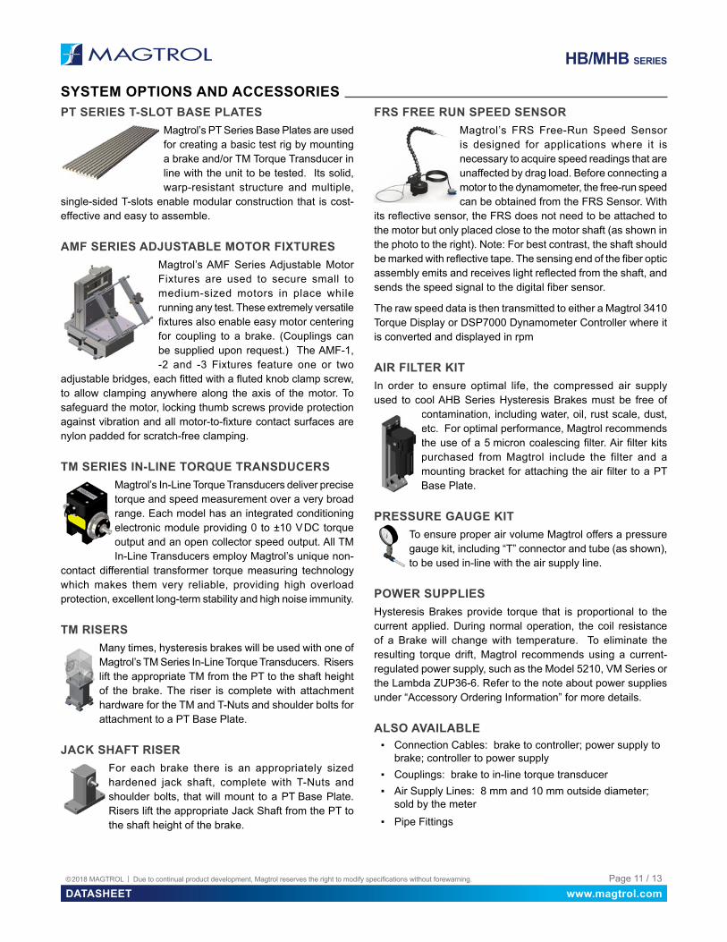
FRS FREE RUN SPEED SENSORMagtrol’s FRS Free-Run Speed Sensor is designed for applications where it is necessary to acquire speed readings that are unaffected by drag load. Before connecting a motor to the dynamometer, the free-run speed can be obtained from the FRS Sensor. With
its reflective sensor, the FRS does not need to be attached to the motor but only placed close to the motor shaft (as shown in the photo to the right). Note: For best contrast, the shaft should be marked with reflective tape. The sensing end of the fiber optic assembly emits and receives light reflected from the shaft, and sends the speed signal to the digital fiber sensor.
The raw speed data is then transmitted to either a Magtrol 3410 Torque Display or DSP7000 Dynamometer Controller where it is converted and displayed in rpm
AIR FILTER KITIn order to ensure optimal life, the compressed air supply used to cool AHB Series Hysteresis Brakes must be free of
contamination, including water, oil, rust scale, dust, etc. For optimal performance, Magtrol recommends the use of a 5 micron coalescing filter. Air filter kits purchased from Magtrol include the filter and a mounting bracket for attaching the air filter to a PT Base Plate.
PRESSURE GAUGE KITTo ensure proper air volume Magtrol offers a pressure gauge kit, including “T” connector and tube (as shown), to be used in-line with the air supply line.
POWER SUPPLIESHysteresis Brakes provide torque that is proportional to the current applied. During normal operation, the coil resistance of a Brake will change with temperature. To eliminate the resulting torque drift, Magtrol recommends using a current-regulated power supply, such as the Model 5210, VM Series or the Lambda ZUP36-6. Refer to the note about power supplies under “Accessory Ordering Information” for more details.
ALSO AVAILABLE ▪ Connection Cables: brake to controller; power supply to
brake; controller to power supply ▪ Couplings: brake to in-line torque transducer ▪ Air Supply Lines: 8 mm and 10 mm outside diameter;
sold by the meter ▪ Pipe Fittings

www.magtrol.comDATASHEETPage 12 / 13© 2018 MAGTROL | Due to continual product development, Magtrol reserves the right to modify specifications without forewarning.
HB/MHB SERIES
T
P
O
R
Q
S
X
Y
ØW Thru Holes(3) Drill Thru andCounter-bore forSocket HeadCap Screws
V
ØU
ENGLISH DIMENSIONS
PILLOW BLOCK MODEL
FOR BRAKE MODELS O P Q R S T ØU V ØW X Y
4736 HB-2.5, MHB-2.5 1.75 1.500 0.25 1.000 1.500 0.25 0.750 #4-40 0.125 0.125 0.25
4702 HB-8, MHB-10.5 2.50 2.125 0.38 1.437 2.125 0.38 0.687 #4-40 0.201 0.187 0.38
4703 HB-16 2.50 2.125 0.38 1.437 2.125 0.38 0.750 #4-40 0.201 0.187 0.38
4705 HB-32, HB-50, MHB-38, MHB-50 2.50 2.125 0.38 1.437 2.125 0.38 0.906 #6-32 0.201 0.187 0.38
4711 HB-140, MHB-140 4.00 3.500 0.38 2.000 3.187 0.50 1.500 #8-32 0.204 0.250 0.50
4714 HB-250, MHB-250 4.00 2.500 0.38 2.375 3.687 0.50 1.750 #10-32 0.204 0.250 0.50
4717 HB-450, MHB-450 4.62 4.000 0.50 3.000 4.310 0.56 1.750 #10-32 0.204 0.250 0.504720 HB-750, MHB-750 5.25 4.500 0.75 3.250 5.125 0.75 2.750 #¼-20 0.343 0.375 0.75
4722 HB-1750, MHB-1750 7.50 6.500 1.00 5.000 7.000 1.00 3.000 #¼-20 0.328 0.500 1.00
METRIC DIMENSIONS
PILLOW BLOCK MODEL
FOR BRAKE MODELS O P Q R S T ØU V ØW X Y
4723 HB-3M-2, MHB-3M-2 44.5 38.0 6.4 25.4 38.1 7.4 19.0 M2.5 3.4 3.2 6.4
4700 HB-10M-2, MHB-10M-2 63.5 54.0 9.7 36.5 53.9 10.4 19.0 M2.5 5.5 4.7 9.5
4704 HB-20M-2, MHB-20M-2 63.5 54.0 9.7 36.5 53.9 10.4 21.0 M3 5.5 4.7 9.5
4706 HB-50M-2, MHB-50M-2 63.5 54.0 9.7 36.5 53.9 10.4 25.0 M4 5.5 4.7 9.5
4864 HB-140M-2, MHB-140M-2 101.6 90.0 9.7 50.0 80.9 12.7 38.0 M4 4.5 6.4 12.7
4865 HB-250M-2, MHB-250M-2 101.6 90.0 9.7 60.0 93.7 12.7 45.0 M5 5.5 6.4 12.7
4866 HB-450M-2, MHB-450M-2 117.3 104.0 12.7 76.0 120.4 14.2 60.0 M5 6.6 6.4 12.74858 HB-750M-2, MHB-750M-2 133.4 115.0 19.1 83.0 130.6 19.1 70.0 M6 9.0 9.5 19.1
4867 HB-1750M-2, MHB-1750M-2 190.5 166.0 25.4 120.0 177.8 25.4 100.0 M6 11.0 12.7 25.4
HB/MHB PILLOW BLOCKSPillow Block Assemblies are an available option for all brake units except the HB-3500 and HB-3500M.
SYSTEM OPTIONS AND ACCESSORIES
© 2018 MAGTROL | Due to continual product development, Magtrol reserves the right to modify specifications without forewarning. Page 13 / 13
Offices in: GermanyFrance - China - India
Worldwide Distribution Network
MAGTROL INC70 Gardenville ParkwayBuffalo NY 14224 | USA
MAGTROL SARoute de Montena 771728 Rossens | Switzerland
phone +1 716 668 5555 fax +1 716 668 8705 e-mail [email protected]
phone +41 26 407 30 00 fax +41 26 407 30 01 e-mail [email protected]
www.magtrol.comDATASHEET
HB
/MH
B H
YS
TER
ES
IS B
RA
KE
S -
US
08/
2018
HB/MHB SERIES
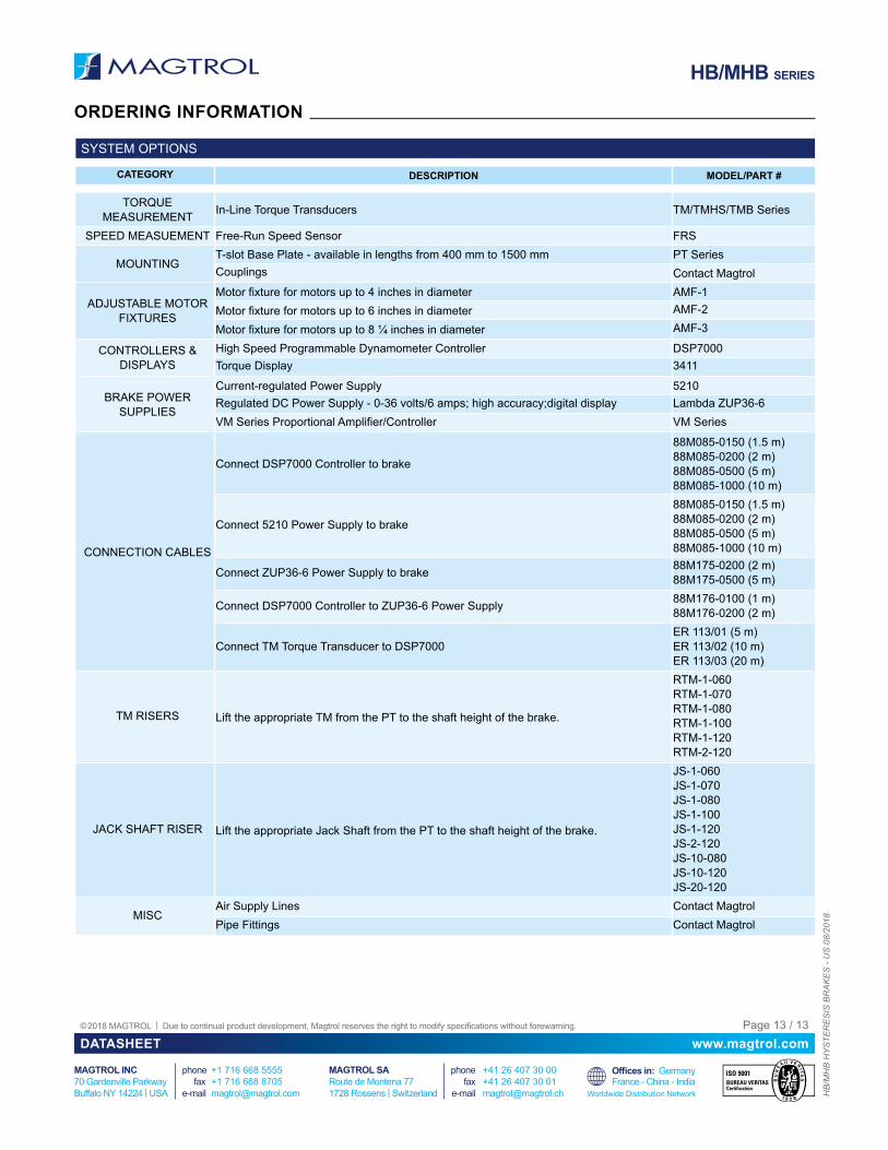
ORDERING INFORMATION
SYSTEM OPTIONS
CATEGORY DESCRIPTION MODEL/PART #
TORQUE MEASUREMENT In-Line Torque Transducers TM/TMHS/TMB Series
SPEED MEASUEMENT Free-Run Speed Sensor FRS
MOUNTINGT-slot Base Plate - available in lengths from 400 mm to 1500 mm PT SeriesCouplings Contact Magtrol
ADJUSTABLE MOTOR FIXTURES
Motor fixture for motors up to 4 inches in diameter AMF-1Motor fixture for motors up to 6 inches in diameter AMF-2
Motor fixture for motors up to 8 ¼ inches in diameter AMF-3
CONTROLLERS & DISPLAYS
High Speed Programmable Dynamometer Controller DSP7000Torque Display 3411
BRAKE POWER SUPPLIES
Current-regulated Power Supply 5210Regulated DC Power Supply - 0-36 volts/6 amps; high accuracy;digital display Lambda ZUP36-6VM Series Proportional Amplifier/Controller VM Series
CONNECTION CABLES
Connect DSP7000 Controller to brake
88M085-0150 (1.5 m)88M085-0200 (2 m)88M085-0500 (5 m)88M085-1000 (10 m)
Connect 5210 Power Supply to brake
88M085-0150 (1.5 m)88M085-0200 (2 m)88M085-0500 (5 m)88M085-1000 (10 m)
Connect ZUP36-6 Power Supply to brake 88M175-0200 (2 m)88M175-0500 (5 m)
Connect DSP7000 Controller to ZUP36-6 Power Supply 88M176-0100 (1 m)88M176-0200 (2 m)
Connect TM Torque Transducer to DSP7000ER 113/01 (5 m)ER 113/02 (10 m)ER 113/03 (20 m)
TM RISERS Lift the appropriate TM from the PT to the shaft height of the brake.
RTM-1-060RTM-1-070RTM-1-080RTM-1-100RTM-1-120RTM-2-120
JACK SHAFT RISER Lift the appropriate Jack Shaft from the PT to the shaft height of the brake.
JS-1-060JS-1-070JS-1-080JS-1-100JS-1-120JS-2-120JS-10-080JS-10-120JS-20-120
MISCAir Supply Lines Contact MagtrolPipe Fittings Contact Magtrol