
HB_CP340_b
198
SIMATIC S7-300 PtP coupling and configuration of CP 340 _ _____________ _ _____________ _ _____________ _ _____________ _ _____________ _ _____________ _ _____________ _ _____________ _ _____________ _ _____________ _ _____________ _ _____________ _ _____________ Preface Product Description 1 Basic Principles of Serial Data Transmission 2 Starting up the CP 340 3 Mounting the CP 340 4 Configuring and Parameterizing the CP 340 5 Communication using function blocks 6 Startup 7 Diagnostics with the CP 340 8 Programming Example for Standard Function Blocks 9 Technical Specifications A Connecting Cables B Accessories and Order Numbers C Literature on SIMATIC S7 D SIMATIC S7-300 PtP coupling and configuration of CP 340 Manual 10/2007 A5E00369892-02
-
Upload
mario-silva -
Category
Documents
-
view
41 -
download
4
Transcript of HB_CP340_b

SIMATIC S7-300 PtP coupling and configuration of CP 340
______________________________________________________________________________________________________________________________________________________________________________________
Preface
Product Description 1
Basic Principles of Serial Data Transmission
2
Starting up the CP 340 3
Mounting the CP 340 4
Configuring and Parameterizing the CP 340
5Communication using function blocks
6
Startup 7
Diagnostics with the CP 340 8
Programming Example for Standard Function Blocks
9
Technical Specifications A
Connecting Cables B
Accessories and Order Numbers
C
Literature on SIMATIC S7 D
SIMATIC
S7-300 PtP coupling and configuration of CP 340
Manual
10/2007 A5E00369892-02

Safety Guidelines Safety Guidelines This manual contains notices you have to observe in order to ensure your personal safety, as well as to prevent damage to property. The notices referring to your personal safety are highlighted in the manual by a safety alert symbol, notices referring only to property damage have no safety alert symbol. These notices shown below are graded according to the degree of danger.
DANGER indicates that death or severe personal injury will result if proper precautions are not taken.
WARNING indicates that death or severe personal injury may result if proper precautions are not taken.
CAUTION with a safety alert symbol, indicates that minor personal injury can result if proper precautions are not taken.
CAUTION without a safety alert symbol, indicates that property damage can result if proper precautions are not taken.
NOTICE indicates that an unintended result or situation can occur if the corresponding information is not taken into account.
If more than one degree of danger is present, the warning notice representing the highest degree of danger will be used. A notice warning of injury to persons with a safety alert symbol may also include a warning relating to property damage.
Qualified Personnel The device/system may only be set up and used in conjunction with this documentation. Commissioning and operation of a device/system may only be performed by qualified personnel. Within the context of the safety notes in this documentation qualified persons are defined as persons who are authorized to commission, ground and label devices, systems and circuits in accordance with established safety practices and standards.
Prescribed Usage Note the following:
WARNING This device may only be used for the applications described in the catalog or the technical description and only in connection with devices or components from other manufacturers which have been approved or recommended by Siemens. Correct, reliable operation of the product requires proper transport, storage, positioning and assembly as well as careful operation and maintenance.
Trademarks All names identified by ® are registered trademarks of the Siemens AG. The remaining trademarks in this publication may be trademarks whose use by third parties for their own purposes could violate the rights of the owner.
Disclaimer of Liability We have reviewed the contents of this publication to ensure consistency with the hardware and software described. Since variance cannot be precluded entirely, we cannot guarantee full consistency. However, the information in this publication is reviewed regularly and any necessary corrections are included in subsequent editions.
Siemens AG Automation and Drives Postfach 48 48 90327 NÜRNBERG GERMANY
Ordernumber: A5E00369892-02 Ⓟ 12/2007
Copyright © Siemens AG 2007. Technical data subject to change
PtP coupling and configuration of CP 340 Manual, 10/2007, A5E00369892-02 3
Preface
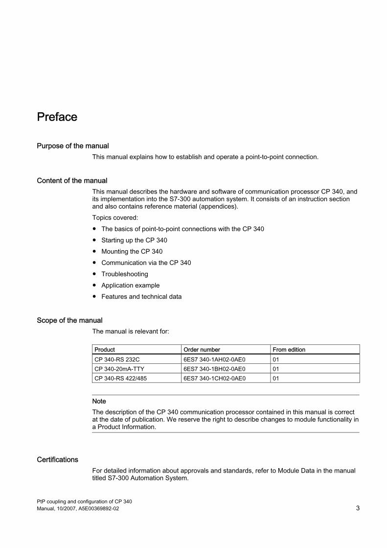
Purpose of the manual This manual explains how to establish and operate a point-to-point connection.
Content of the manual This manual describes the hardware and software of communication processor CP 340, and its implementation into the S7-300 automation system. It consists of an instruction section and also contains reference material (appendices). Topics covered: ● The basics of point-to-point connections with the CP 340 ● Starting up the CP 340 ● Mounting the CP 340 ● Communication via the CP 340 ● Troubleshooting ● Application example ● Features and technical data
Scope of the manual The manual is relevant for:
Product Order number From edition CP 340-RS 232C 6ES7 340-1AH02-0AE0 01 CP 340-20mA-TTY 6ES7 340-1BH02-0AE0 01 CP 340-RS 422/485 6ES7 340-1CH02-0AE0 01
Note The description of the CP 340 communication processor contained in this manual is correct at the date of publication. We reserve the right to describe changes to module functionality in a Product Information.
Certifications For detailed information about approvals and standards, refer to Module Data in the manual titled S7-300 Automation System.

Preface
PtP coupling and configuration of CP 340 4 Manual, 10/2007, A5E00369892-02
Assistance in using the manual This manual has the following features to help you to find the information you need quickly: ● In the chapters, the information in the left-hand column of each page summarizes the
content of each section. ● Following the appendices, a glossary defines important technical terms used in the
manual. ● At the end of the manual a comprehensive index facilitates quick access to information
relating to specific subjects.
Additional assistance Please contact your local Siemens representative if you have any queries about the products described in this manual. ● You will find contact details for your representative at:
http://www.siemens.com/automation/partner ● You will find the guide to the technical documentation for the individual SIMATIC products
and systems at: http://www.siemens.de/simatic-tech-doku-portal
● You will find the online catalog and online ordering system at: http://mall.automation.siemens.com
Conventions The abbreviation CP 340 is used in this manual when information applies to all three module variants: CP 340-RS 232C, CP 340-20mA TTY and CP 340-RS 422/485.
Training centers We offer a range of courses to help get you started with the S7 programmable controller. Please contact your regional training center, or the central training center in Nuremberg, Germany. Phone: +49 (911) 895-3200. Internet: http://www.sitrain.com
Technical support You can access technical support for all A&D products ● Via the support request form available online
http://www.siemens.de/automation/support-request ● Phone: + 49 180 5050 222 ● Fax: + 49 180 5050 223 You will find more information about our technical support on the Internet at http://www.siemens.de/automation/service.
Preface
PtP coupling and configuration of CP 340 Manual, 10/2007, A5E00369892-02 5
Service & Support on the Internet Supplementary to our documentation offers, we provide a comprehensive online knowledge base on the Internet. http://www.siemens.com/automation/service&support
There you will find: ● The newsletter, which is constantly updated to provide you with the latest information
about your products ● The right documents via our Search function under Service & Support ● A forum, where users and experts from all over the world exchange their experiences
● Your local representative for Automation & Drives via our representatives database ● Information about on-site service, repairs and spare parts Lots more is available to you in
the "Service" section.

Preface
PtP coupling and configuration of CP 340 6 Manual, 10/2007, A5E00369892-02

PtP coupling and configuration of CP 340 Manual, 10/2007, A5E00369892-02 7
Table of contents Preface ...................................................................................................................................................... 3 1 Product Description ................................................................................................................................. 11
1.1 Uses of the CP 340......................................................................................................................11 1.2 Components for a Point-to-Point Connection ..............................................................................13 1.2.1 Required Hardware Components ................................................................................................13 1.2.2 Software Components for a Point-to-Point Connection with the CP 340 ....................................14 1.3 Design of the CP 340...................................................................................................................15 1.4 Properties of the serial interface ..................................................................................................17 1.4.1 RS 232C interface of the CP 340–RS 232C................................................................................17 1.4.2 20mA–TTY interface on the CP 340–20mA-TTY.........................................................................18 1.4.3 X27 (RS 422/485) Interface of the CP 340–RS 422/485 .............................................................19
2 Basic Principles of Serial Data Transmission........................................................................................... 21 2.1 Serial Transmission of a Character .............................................................................................21 2.2 Transmission mode in Point-to-Point Communication.................................................................26 2.3 Transmission integrity ..................................................................................................................28 2.4 Data Transmission with the printer driver ....................................................................................30 2.5 Data Transmission with the 3964(R) Procedure..........................................................................34 2.5.1 Control characters........................................................................................................................34 2.5.2 Block Checksum ..........................................................................................................................35 2.5.3 Sending Data with 3964(R)..........................................................................................................36 2.5.4 Receiving Data with 3964(R) .......................................................................................................38 2.5.5 Handling Errored Data .................................................................................................................40 2.6 Data transfer using the ASCII driver ............................................................................................43 2.6.1 RS 232C Secondary Signals .......................................................................................................43 2.6.2 Sending Data with the ASCII Driver.............................................................................................47 2.6.3 Receiving Data with the ASCII Driver ..........................................................................................48 2.6.4 BREAK - Monitoring on CP 340...................................................................................................52 2.6.5 Receive Buffer on CP 340 ...........................................................................................................52 2.7 Parameterization Data .................................................................................................................53 2.7.1 Basic parameters of the CP 340..................................................................................................53 2.7.2 Parameterization Data of the 3964(R) Procedure .......................................................................54 2.7.3 Parameterization data of the ASCII driver ...................................................................................59 2.7.4 Parameterization data of the printer driver ..................................................................................64 2.7.5 Conversion and Control Statements for Printer Output .............................................................669

Table of contents
PtP coupling and configuration of CP 340 8 Manual, 10/2007, A5E00369892-02
3 Starting up the CP 340 ............................................................................................................................ 79 4 Mounting the CP 340 ............................................................................................................................... 81
4.1 CP 340 slots................................................................................................................................ 81 4.2 Installing and removing the CP 340 ............................................................................................ 82 4.2.1 Installation steps ......................................................................................................................... 82 4.2.2 Removal steps ............................................................................................................................ 83
5 Configuring and Parameterizing the CP 340............................................................................................ 85 5.1 Parameterization Options............................................................................................................ 85 5.2 Parameterizing the Communications Protocols .......................................................................... 86 5.2.1 Parameterization of the CP 340.................................................................................................. 86 5.2.2 Installing the engineering tool ..................................................................................................... 87 5.3 Configuring the CP 340............................................................................................................... 88 5.4 Managing the Parameter Data.................................................................................................... 89 5.5 Identification data ........................................................................................................................ 90 5.6 Download of firmware updates ................................................................................................... 92
6 Communication using function blocks...................................................................................................... 95 6.1 Technical data of the function blocks.......................................................................................... 95 6.2 Communication via Function Blocks ........................................................................................... 98 6.3 Overview of the Function Blocks................................................................................................. 99 6.4 Using the function blocks for connecting to a communications processor ............................... 100 6.4.1 S7 sends data to a communication partner .............................................................................. 100 6.4.2 S7 receives data from a communication partner ...................................................................... 104 6.5 Using function blocks for the output of message texts to a printer ........................................... 108 6.6 Use of function blocks for reading and controlling the RS 2332C secondary signals .............. 113 6.7 Delete receive buffer, FB12 "P_RESET" .................................................................................. 117 6.8 Parameterizing the Function Blocks ......................................................................................... 120 6.8.1 General Information on Data Block Assignment....................................................................... 120 6.8.2 Parameterizing the Data Blocks................................................................................................ 122 6.9 General Information on Program Processing............................................................................ 126
7 Startup................................................................................................................................................... 127 7.1 Operating Modes of the CP 340 ............................................................................................... 127 7.2 Startup Characteristics of the CP 340....................................................................................... 128 7.3 Behavior of the CP 340 on Operating Mode Transitions of the CPU........................................ 129
8 Diagnostics with the CP 340 .................................................................................................................. 131 8.1 Diagnosis via the Display Elements of the CP 340................................................................... 132 8.2 Diagnostics Messages of the Function Blocks P_SEND, P_RCV and P_PRINT ..................... 133 8.3 Diagnostics via the S7-300 backplane bus ............................................................................... 140 8.4 Diagnostics by means of the diagnostic buffer of the CP 340 .................................................. 142

Table of contents
PtP coupling and configuration of CP 340 Manual, 10/2007, A5E00369892-02 9
9 Programming Example for Standard Function Blocks............................................................................ 145 9.1 Device Configuration..................................................................................................................146 9.2 Settings ......................................................................................................................................146 9.3 Blocks Used ...............................................................................................................................148 9.4 Example “Point–to–Point Communication” ................................................................................149 9.5 Example "Printing" and "Reading and Controlling the CP 340 Inputs/Outputs" ........................151 9.6 Installation, Error Messages ......................................................................................................153 9.7 Activation, Start-Up Program and Cyclic Program.....................................................................154
A Technical Specifications ........................................................................................................................ 157 A.1 Technical Specifications of the CP 340 .....................................................................................157 A.2 Recycling and Disposal..............................................................................................................162
B Connecting Cables ................................................................................................................................ 163 B.1 RS 232C interface of the CP 340–RS 232C..............................................................................163 B.2 20 mA TTY interface on the CP 340-20mA-TTY .......................................................................171 B.3 X27 (RS 422/485) Interface of the CP 340–RS 422/485 ...........................................................178
C Accessories and Order Numbers........................................................................................................... 183 D Literature on SIMATIC S7...................................................................................................................... 185 Glossary ................................................................................................................................................ 189 Index...................................................................................................................................................... 195

Table of contents
PtP coupling and configuration of CP 340 10 Manual, 10/2007, A5E00369892-02

PtP coupling and configuration of CP 340 Manual, 10/2007, A5E00369892-02 11
Product Description 11.1 Uses of the CP 340
Introduction The communication processor allows you to exchange data between programmable controllers or computers by means of point-to-point communication.
Functionality of the CP 340 The CP 340 communication processor provides the following functionality: ● Transmission rate up to 19.2 Kbaud, half duplex ● Integration of the most important transmission protocols in the module firmware:
– 3964(R) procedure – ASCII driver – Printer driver
● Adaptation of transmission protocols by means of parameterization with the CP 340 parameter assignment user interface: Point-to-point communication, parameter assignment
● Integrated serial interface: Three module variants are available, each having a different interface type that is suitable for different communication partners (see Module variants table).
Module variants The following variants of the communication processor are available:
Table 1-1 Module variants of the communication processor
Module Order number Integrated interface CP 340–RS 232C 6ES7 340–1AH02–0AE0 RS 232C interface CP 340–20mA–TTY 6ES7 340–1BH02–0AE0 20mA-TTY interface CP 340–RS 422/485 6ES7 340–1CH02–0AE0 X27 (RS 422/485) interface
Product Description 1.1 Uses of the CP 340
PtP coupling and configuration of CP 340 12 Manual, 10/2007, A5E00369892-02
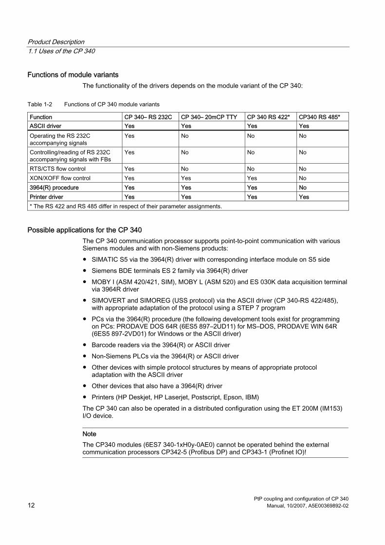
Functions of module variants The functionality of the drivers depends on the module variant of the CP 340:
Table 1-2 Functions of CP 340 module variants
Function CP 340– RS 232C CP 340– 20mCP TTY CP 340 RS 422* CP340 RS 485* ASCII driver Yes Yes Yes Yes Operating the RS 232C accompanying signals
Yes No No No
Controlling/reading of RS 232C accompanying signals with FBs
Yes No No No
RTS/CTS flow control Yes No No No XON/XOFF flow control Yes Yes Yes No 3964(R) procedure Yes Yes Yes No Printer driver Yes Yes Yes Yes * The RS 422 and RS 485 differ in respect of their parameter assignments.
Possible applications for the CP 340 The CP 340 communication processor supports point-to-point communication with various Siemens modules and with non-Siemens products: ● SIMATIC S5 via the 3964(R) driver with corresponding interface module on S5 side ● Siemens BDE terminals ES 2 family via 3964(R) driver ● MOBY I (ASM 420/421, SIM), MOBY L (ASM 520) and ES 030K data acquisition terminal
via 3964R driver ● SIMOVERT and SIMOREG (USS protocol) via the ASCII driver (CP 340-RS 422/485),
with appropriate adaptation of the protocol using a STEP 7 program ● PCs via the 3964(R) procedure (the following development tools exist for programming
on PCs: PRODAVE DOS 64R (6ES5 897–2UD11) for MS–DOS, PRODAVE WIN 64R (6ES5 897-2VD01) for Windows or the ASCII driver)
● Barcode readers via the 3964(R) or ASCII driver ● Non-Siemens PLCs via the 3964(R) or ASCII driver ● Other devices with simple protocol structures by means of appropriate protocol
adaptation with the ASCII driver ● Other devices that also have a 3964(R) driver ● Printers (HP Deskjet, HP Laserjet, Postscript, Epson, IBM) The CP 340 can also be operated in a distributed configuration using the ET 200M (IM153) I/O device.
Note The CP340 modules (6ES7 340-1xH0y-0AE0) cannot be operated behind the external communication processors CP342-5 (Profibus DP) and CP343-1 (Profinet IO)!

Product Description 1.2 Components for a Point-to-Point Connection
PtP coupling and configuration of CP 340 Manual, 10/2007, A5E00369892-02 13
1.2 Components for a Point-to-Point Connection
Introduction The PtP connection between the communication processor and a communication partner requires specific hardware and software components.
1.2.1 Required Hardware Components
Hardware Components The table below describes the hardware components for a point-to-point connection.
Table 1-3 Hardware-Components for a Point-to-Point Connection
Components Function Diagram Mounting rack ... provides the mechanical and electrical
connections of the S7–300.
Power supply module (PS) ... converts the line voltage (120/230 VAC) into the operating voltage of 24 VDC required to supply the S7-300.
Central Processing Unit (CPU) Accessories: • Memory Card • Backup battery
... executes the application program; communicates via the MPI interface with other CPUs or with a programming device.
Communications processor ... communicates via the interface with a communication partner.
Standard Connecting Cable ... connects the communications processor to the communication partner.
Standard connecting cable ... connects a CPU to a PG/PC.

Product Description 1.2 Components for a Point-to-Point Connection
PtP coupling and configuration of CP 340 14 Manual, 10/2007, A5E00369892-02
Components Function Diagram Programming device (PG) or PC ... communicates with the CPU of the S7-300.
1.2.2 Software Components for a Point-to-Point Connection with the CP 340
Software Components The following table lists the software components required for establishing a point-to-point connection with the CP 340.
Table 1-4 Software Components for a Point-to-Point Connection with the CP 340
Components Function Diagram STEP 7 software package ... configures, parameterizes, programs
and tests the S7-300. +
Parameterization interface CP 340: Parameterize Point-to-Point Communication, Parameter Assignment
... parameterizes the interface of the CP 340.
Function blocks (FBs) with programming example
... control communication between the CPU and the CP 340.

Product Description 1.3 Design of the CP 340
PtP coupling and configuration of CP 340 Manual, 10/2007, A5E00369892-02 15
1.3 Design of the CP 340
Introduction The CP 340 communication processor is supplied with an integrated serial interface.
Positions of module elements The figure shows the positions of the module elements on the front panel of the CP 340 communication processor.
Figure 1-1 Positions of the module elements on the CP 340 communication processor
LED display elements The following LED display elements are located on the front panel of the communication processor: ● SF (red) error LED ● TxD (green) interface transmitting ● RxD (green) interface receiving

Product Description 1.3 Design of the CP 340
PtP coupling and configuration of CP 340 16 Manual, 10/2007, A5E00369892-02
Integrated interface The CP 340 is available in three variants with different interface types: ● RS 232C ● X27 (RS 422/485) ● 20mA-TTY The interface types are indicated on the front of the CP 340.
Bus connector for the S7 backplane bus A bus connector is supplied with the CP 340. The bus connector is plugged onto the back panel of the CP 340 when it is mounted. The S7-300 backplane bus is connected via the bus connector. The S7-300 backplane bus is a serial data bus via which the CP 340 communicates with the modules of the programmable controller and is supplied with the necessary voltage.
Figure 1-2 Connector S7
See also Diagnosis via the Display Elements of the CP 340 (Page 132)

Product Description 1.4 Properties of the serial interface
PtP coupling and configuration of CP 340 Manual, 10/2007, A5E00369892-02 17
1.4 Properties of the serial interface
Introduction Three module variants of the CP 340 are available, each having a different interface type that is suitable for different communication partners. For point-to-point connections between the CP 340 and a communication partner, Siemens offers standard connecting cables in various lengths.
1.4.1 RS 232C interface of the CP 340–RS 232C
Features The RS 232C interface is a voltage interface used for serial data transmission in compliance with the RS 232C standard. ● Type: Voltage interface ● Front connector: 9-pin sub D male connector with screw-locking ● RS 232C signals: TXD, RXD, RTS, CTS, DTR, DSR, RI, DCD, GND; all isolated from S7-
internal power supply ● Max. baud rate:
– 19.2 Kbaud (3964(R) procedure) – 9.6 Kbaud (ASCII driver, printer driver)
● Max. cable length: 15 m, cable type LIYCY 7 x 0.14 ● Standard: DIN 66020, DIN 66259, ● EIA-RS 232C, CCITT V.24/V.28 ● Degree of protection: IP00

Product Description 1.4 Properties of the serial interface
PtP coupling and configuration of CP 340 18 Manual, 10/2007, A5E00369892-02
RS 232C signals The table below shows the meaning of the RS 232C accompanying signals.
Table 1-5 RS 232C interface signals
Signal Designation Meaning TXD Transmitted Data Transmitted data; transmission line is maintained at logic "1" by the communication
processor in idle state. RXD Received Data Received data; receive line must be maintained at logic "1" by communication
partner. RTS Request To Send RTS "ON": Communication processor is ready to send.
RTS "OFF": Communication processor is not sending. CTS Clear Tto Ssend Communication partner can receive data from the communication processor. The
communication processor expects this signal in response to RTS "ON". DTR Data Terminal Ready DTR "ON": Communication processor is active and ready for operation.
DTR "OFF": Communication processor is not active and not ready for operation. DSR Data Set Ready DSR "ON": Communication partner is active and ready for operation.
DSR "OFF": Communication partner is not active and not ready for operation. RI Ring Indicator Incoming call when connecting a modem DCD Data Carrier Detect Carrier signal when connecting a modem
1.4.2 20mA–TTY interface on the CP 340–20mA-TTY
Definition The 20mA-TTY interface is a current-loop interface used for serial data transmission.
Features The 20mA-TTY interface has the following features and meets the following requirements: ● Type: Current-loop interface ● Front connector: 9-pin sub D socket with screw-locking ● 20 mA-TTY signals, two isolated 20 mA current sources, receiving loop (RX) "–" and "+"
send loop (TX) "–" and "+"; all isolated from the S7-internal power supply ● Max. baud rate: 9.6 Kbaud ● Max. cable length: 100 m active, 1,000 m passive;
cable type LIYCY 7 x 0.14 ● Standard: DIN 66258 Part 1 ● Degree of protection: IP00

Product Description 1.4 Properties of the serial interface
PtP coupling and configuration of CP 340 Manual, 10/2007, A5E00369892-02 19
1.4.3 X27 (RS 422/485) Interface of the CP 340–RS 422/485
Definition The X27 (RS 422/485) interface is a voltage-difference interface for serial data transmission in compliance with the X27 standard.
Properties The X27 (RS 422/485) interface has the following properties and fulfills the following requirements: ● Type: Differential voltage interface ● Front connector: 15-pin sub-D female, with screwed interlock ● RS 422 Signals: TXD (A), RXD (A), TXD (B), RXD (B), GND;
All isolated against S7-internal power supply ● RS 485 Signals: R/T (A), R/T (B), GND;
All isolated against the S7-internal power supply ● Max. transmission rate:
– 19.2 kbps (3964(R) procedure) – 9.6 kbps (ASCII driver, printer driver)
● Max. cable length: 1,200 m, cable type LIYCY 7 0.14 ● Standard: DIN 66259 Parts 1 and 3, EIA-RS 422/485, CCITT V.11 ● Degree of protection: IP 00
Note The X27 (RS 422/485) interface can only be run in 4-wire mode with the 3964 procedure.

Product Description 1.4 Properties of the serial interface
PtP coupling and configuration of CP 340 20 Manual, 10/2007, A5E00369892-02
PtP coupling and configuration of CP 340 Manual, 10/2007, A5E00369892-02 21
Basic Principles of Serial Data Transmission 22.1 Serial Transmission of a Character
Introduction The system provides various networking options for the exchange of data between two or more communication partners. The simplest form of data interchange is via a point-to-point connection between two communication partners.
Point-to-point communication In point-to-point communication the communications processor forms the interface between a programmable controller and a communication partner. In PtP communication with communication processor, data are transferred via serial interface.
Serial Transmission In serial transmission, the individual bits of each byte of information are transmitted one after the other in a fixed order.
Unidirectional/Bidirectional Data Traffic The CP 340 itself handles data transmission with communication partners via the serial interface. The CP 340 is equipped with three different drivers for this purpose. ● Unidirectional data traffic:
– Printer Driver ● Bidirectional data traffic:
– ASCII driver – 3964(R) procedure
The CP 340 handles data transmission via the serial interface in accordance with the interface type and the selected driver.
Unidirectional Data Traffic - Printer Output In the case of printer output (printer driver), n bytes of user data are output to a printer. No characters are received. The only exception to this are data flow control characters (e.g. XON/XOFF).

Basic Principles of Serial Data Transmission 2.1 Serial Transmission of a Character
PtP coupling and configuration of CP 340 22 Manual, 10/2007, A5E00369892-02
Bidirectional Data Traffic - Operating Modes The CP 340 has two operating modes for bidirectional data traffic: ● Half-duplex operation (3964(R) procedure, ASCII driver)
Data are exchanged between the communication partners, but only in one direction at a time. In half-duplex operation, therefore, at any one time data is being either sent or received. The exception to this may be individual control characters for data flow control (e.g. XON/XOFF), which can also be sent during a receive operation or received during a send operation.
● Full-duplex operation (ASCII driver) Data are exchanged between two or more communication partners in both directions simultaneously. In full-duplex mode, data can be sent and received at the same time. Every communication partner must be able to operate a send and a receive facility simultaneously.
You can choose between half-duplex operation (RS 485) and full-duplex operation (RS 422) when using the CP 340-RS 422/485 module variant.
Asynchronous Data Transmission With the communications processor, serial transmission occurs asynchronously. The so-called timebase synchronism (a fixed timing code used in the transmission of a fixed character string) is only upheld during transmission of a character. Each character to be sent is preceded by a synchronization impulse, or start bit. The length of the start-bit transmission determines the clock pulse. The end of the character transmission is signaled by the stop bit.
Declarations As well as the start and stop bits, further declarations must be made between the sending and receiving partners before serial transmission can take place. These include: ● Transmission speed (baud rate) ● Character and acknowledgment delay times ● Parity ● Number of data bits ● Number of stop bits ● Number of setup and transmission attempts permitted
Character frame Data is transmitted between the CP 340 and a communication partner via the serial interface in a 10-bit or 11-bit character frame. Three data formats are available for each character frame. You can assign parameters to the format you require using the CP 340: Point-to-Point Communication, Parameter Assignment parameterization interface.

Basic Principles of Serial Data Transmission 2.1 Serial Transmission of a Character
PtP coupling and configuration of CP 340 Manual, 10/2007, A5E00369892-02 23
10-Bit Character Frame The figure below shows the three possible data formats for an 10-bit character frame.
Figure 2-1 10-Bit Character Frame

Basic Principles of Serial Data Transmission 2.1 Serial Transmission of a Character
PtP coupling and configuration of CP 340 24 Manual, 10/2007, A5E00369892-02
11-Bit Character Frame The figure below shows the three possible data formats for an 11-bit character frame.
Figure 2-2 11-Bit Character Frame

Basic Principles of Serial Data Transmission 2.1 Serial Transmission of a Character
PtP coupling and configuration of CP 340 Manual, 10/2007, A5E00369892-02 25
Character Delay Time The figure below shows the maximum time permitted between two characters received within a message frame. This is known as the character delay time.
Figure 2-3 Character Delay Time

Basic Principles of Serial Data Transmission 2.2 Transmission mode in Point-to-Point Communication
PtP coupling and configuration of CP 340 26 Manual, 10/2007, A5E00369892-02
2.2 Transmission mode in Point-to-Point Communication
Introduction When data are transmitted, all communication partners must adhere to a fixed set of rules for handling and implementing data traffic. The ISO has defined a 7-layer model, which is recognized as the basis for a worldwide standardization of transmission protocols for computer-to-computer communication.
ISO 7-Layer Reference Model for Data Transmission All communication partners must adhere to a fixed set of rules for handling and implementing data traffic. Such rules are called protocols.
Protocol A protocol defines the following points: ● Operating mode
Half-duplex or full-duplex operation ● Initiative
Which communication partners can initiate the transmission and under what conditions ● Control characters
Which control characters are to be used for data transmission ● Character frame
Which character frames are to be used for data transmission. ● Data backup
The data backup procedure to be used ● Character delay time
The time period within which an incoming character must be received. ● Transmission speed
The baud rate in bits/s
Procedure This is the specific process according to which the data is transmitted.

Basic Principles of Serial Data Transmission 2.2 Transmission mode in Point-to-Point Communication
PtP coupling and configuration of CP 340 Manual, 10/2007, A5E00369892-02 27
ISO 7-Layer Reference Model The reference model defines the external behavior of the communication partners. Each protocol layer, except for the lowest one, is embedded in the next one down. The individual layers are as follows: 1. Physical layer
– Physical conditions for communication, e.g. transmission medium, baud rate 2. Data-link layer
– Security procedure for the transmission – Access modes
3. Network layer – Network connections – Addressing for communication between two partners
4. Transport layer – Error-recognition procedure – Debugging – Handshaking
5. Session layer – Establishing communication – Communication control – Terminating communication
6. Presentation layer – Conversion of the standard form of data representation of the communication system
into a device-specific form (data interpretation rules) 7. Application layer
– Defining the communication task and the functions it requires
Processing the Protocols The sending communication partner runs through the protocols from the highest layer (no. 7 - application layer) to the lowest (no. 1 - physical layer), while the receiving partner processes the protocols in the reverse order, i.e. starting with layer 1. Not all protocols have to take all 7 layers into account. If the sending and receiving partners both use the same protocol, layer 6 can be omitted.

Basic Principles of Serial Data Transmission 2.3 Transmission integrity
PtP coupling and configuration of CP 340 28 Manual, 10/2007, A5E00369892-02
2.3 Transmission integrity
Introduction Transmission integrity plays an important role in the transmission of data and in selection of the transmission procedure. Generally speaking, the more layers of the reference model are applied, the greater the transmission integrity.
Classifying the Supplied Protocols The CP 340 governs the following protocols: ● 3964(R) procedure ● ASCII driver ● Printer Driver The figure below illustrates how these supplied protocols of the CP 340 fit into the ISO reference model:
Figure 2-4 Position of the Supplied Protocols of the CP 340 in the ISO Reference Model
Transmission Integrity with the Printer Driver Data Integrity When Using the Printer Driver: ● No data integrity precautions are taken for data transmission with the printer driver. ● To prevent data from being lost in the event of the printer receive buffer overflowing, you
can work with data flow control (XON/XOFF, RTS/CTS). ● When data is output to the printer, the printer's BUSY signal is evaluated. The CP 340
receives the BUSY signal as a CTS signal and evaluates it in the same way (see ASCII driver). Please note that, when using CTS/RTS flow control, you must set the polarity of the BUSY signal to CTS = "OFF" on the printer.
Basic Principles of Serial Data Transmission 2.3 Transmission integrity
PtP coupling and configuration of CP 340 Manual, 10/2007, A5E00369892-02 29
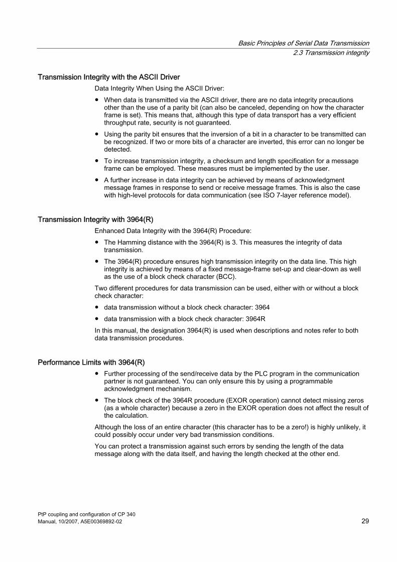
Transmission Integrity with the ASCII Driver Data Integrity When Using the ASCII Driver: ● When data is transmitted via the ASCII driver, there are no data integrity precautions
other than the use of a parity bit (can also be canceled, depending on how the character frame is set). This means that, although this type of data transport has a very efficient throughput rate, security is not guaranteed.
● Using the parity bit ensures that the inversion of a bit in a character to be transmitted can be recognized. If two or more bits of a character are inverted, this error can no longer be detected.
● To increase transmission integrity, a checksum and length specification for a message frame can be employed. These measures must be implemented by the user.
● A further increase in data integrity can be achieved by means of acknowledgment message frames in response to send or receive message frames. This is also the case with high-level protocols for data communication (see ISO 7-layer reference model).
Transmission Integrity with 3964(R) Enhanced Data Integrity with the 3964(R) Procedure: ● The Hamming distance with the 3964(R) is 3. This measures the integrity of data
transmission. ● The 3964(R) procedure ensures high transmission integrity on the data line. This high
integrity is achieved by means of a fixed message-frame set-up and clear-down as well as the use of a block check character (BCC).
Two different procedures for data transmission can be used, either with or without a block check character: ● data transmission without a block check character: 3964 ● data transmission with a block check character: 3964R In this manual, the designation 3964(R) is used when descriptions and notes refer to both data transmission procedures.
Performance Limits with 3964(R) ● Further processing of the send/receive data by the PLC program in the communication
partner is not guaranteed. You can only ensure this by using a programmable acknowledgment mechanism.
● The block check of the 3964R procedure (EXOR operation) cannot detect missing zeros (as a whole character) because a zero in the EXOR operation does not affect the result of the calculation.
Although the loss of an entire character (this character has to be a zero!) is highly unlikely, it could possibly occur under very bad transmission conditions. You can protect a transmission against such errors by sending the length of the data message along with the data itself, and having the length checked at the other end.
Basic Principles of Serial Data Transmission 2.4 Data Transmission with the printer driver
PtP coupling and configuration of CP 340 30 Manual, 10/2007, A5E00369892-02
2.4 Data Transmission with the printer driver
Introduction The printer driver allows you to output date- and time-stamped message texts to a printer. This enables you to monitor simple processes, print error or fault messages or issue instructions to operating personnel, for example. The printer driver contains the physical layer (layer 1).
Message texts and parameters for printout With the CP 340: Point-to-Point Communication, Parameter Assignment user interface, you can configure the message texts and set the parameters (page layout, character set, control characters) for printout. Message texts and printout parameters are transmitted to the CP 340 together with the module parameters when it starts up. Message texts: You can configure message texts with variables and control statements (e.g., for bold, condensed, expanded, or italic type and underlining). Each message text is assigned a number during configuration. A message text is printed if its number is specified in a format string when the P_PRINT function block is called. You must have stored the format string and variables in data blocks beforehand. Page layout: You can configure the margins, possible line breaks and headers and footers. Character set: The ANSI character set is converted to the printer character set by STEP 7 by means of a character conversion table. You can change a character conversion table suggested for a printer type in order to include special characters required for a particular language, for example. Control characters: You can use a control character table to change the control statements in the message text for the printer emulation for switching on and off bold, condensed, expanded, or italic type and underlining, and to add other control characters.
Variables Up to 4 variables (3 + a message text number) can be displayed in a message text. The values of variables can be transmitted from the CPU to the CP 340. The following can be displayed as variables: Calculated values of the user program, such as: levels), date and time, strings (string variables), or other message texts. A conversion statement must be specified in the configured message text or in the format string for each variable, and the meaning and output format of the variable value must be encoded in this statement.

Basic Principles of Serial Data Transmission 2.4 Data Transmission with the printer driver
PtP coupling and configuration of CP 340 Manual, 10/2007, A5E00369892-02 31
Format string The format string allows you to define the display type and composition of a message text. The format string can consist of: ● Text (all printable characters, for example: The level ... l was reached at ... hours.) ● Conversion statements for variables (e.g., %N = pointer to message text number x, where
x is the value of a variable (see example 2 below)). There must be one (and only one) conversion statement for each variable in the format string or configured message text. The conversion statements are applied to the variables in the sequence in which they occur.
● Control statements with control characters for bold, condensed, expanded, italic, and underlining (e.g., \B = bold type on) or with additional control characters you have defined
You can use other control characters if you enter them in the control character table in the CP 340: Point-to-Point Communication, Parameter Assignment user interface and reset the CP 340 parameters.
Additional functions In addition to outputting message texts, you can use the following functions for printout. To execute one of these functions, simply specify it in the format string in the same way. ● Set page number (format string = %P) ● Begin new page (format string = \F) ● Print with/without line break (\x at the end of the format string) Please note that a line feed is carried out by default after each output.
Examples Example 1: The level "200" l was reached at "17.30" hours. Format string = The level %i l was reached at %Z hours. Variable 1 = time Variable 2 = level Example 2: The pressure in the chamber "is falling" Format string = %N %S Variable 1 = 17 (message text no. 17: The pressure in the chamber ...) Variable 2 = reference to string (string variable: ... is falling) Example 3: (Setting the page number to 10) Format string = %P Variable 1 = 10 (page number: 10)

Basic Principles of Serial Data Transmission 2.4 Data Transmission with the printer driver
PtP coupling and configuration of CP 340 32 Manual, 10/2007, A5E00369892-02
Printout To output n bytes of user data to a printer, specify the block number of a pointer DB when calling the P_PRINT function block. The pointers to the data blocks are stored in the pointer DB together with the format string and the variables and in a specific order. During output the data is edited for printing. Print editing is performed as configured in the CP 340: Point-to-Point Communication, Parameter Assignment user interface (page layout, character set, control characters, etc.). Characters are not received during printout, with the exception of any flow control characters that have been configured. Any characters received are not adopted.
Note When XON/XOFF flow control is parameterized, the user data must not contain the parameterized XON or XOFF characters. The default settings are DC1 = 11H for XON and DC3 = 13H for XOFF.
Outputting a message text The figure below illustrates the sequence of operations for a printout.
Figure 2-5 Flow chart of printout

Basic Principles of Serial Data Transmission 2.4 Data Transmission with the printer driver
PtP coupling and configuration of CP 340 Manual, 10/2007, A5E00369892-02 33
Data flow control/Handshaking Handshaking controls the data flow between two communication partners. Handshaking ensures that data is not lost in transmissions between devices that work at different speeds. You can also send message texts with data flow control during printout. There are essentially two types of handshaking: ● Software handshaking (e.g., XON/XOFF) ● Hardware handshaking (e.g., RTS/CTS) Data flow control is implemented as follows on the CP 340 during printout: ● As soon as the CP 340 is switched to the operating mode with flow control by means of
parameterization, it sends the XON character or sets the RTS line to ON. ● CP 340 interrupts the output of characters when it receives the XOFF character, or when
control signal CTS = OFF. If neither an XON character is received nor CTS is set to ON once a configured time has elapsed, printout is aborted and an appropriate error message (0708H) is generated at the STATUS output of the PRINT SFB.
Note When RTS/CTS flow control is parameterized, you must fully wire the interface signals used in the plug connection.
BUSY signal The CP 340 evaluates the printer's "BUSY" control signal. The printer indicates to the CP 340 that it is ready to receive: ● CP 340-20mA-TTY: current on RxD line ● CP 340–RS 232C and CP 340-RS 422/485: CTS signal = "ON".
Note When RTS/CTS flow control is parameterized, you must set the polarity of the BUSY signal on the printer as follows: • BUSY signal: CTS = "OFF" Please note that some printers use the DTR signal to display the BUSY signal. In such cases you must wire the cable to the CP 340 appropriately.
See also Using function blocks for the output of message texts to a printer (Page 108) RS 232C interface of the CP 340–RS 232C (Page 163) Conversion and Control Statements for Printer Output (Page 69) Communication via Function Blocks (Page 98)

Basic Principles of Serial Data Transmission 2.5 Data Transmission with the 3964(R) Procedure
PtP coupling and configuration of CP 340 34 Manual, 10/2007, A5E00369892-02
2.5 Data Transmission with the 3964(R) Procedure
Introduction The 3964(R) procedure control PtP data exchange between the communications processor and a communication partner. As well as the physical layer (layer 1), the 3964(R) procedure also incorporates the data-link layer (layer 2).
2.5.1 Control characters
Introduction During data transmission, the 3964(R) procedure adds control characters to the user data (data-link layer). These control characters allow the communication partner to check whether the data has arrived complete and without errors.
The control characters of the 3964(R) Procedure The 3964(R) procedure analyzes the following control codes: ● STX Start of Text;
Start of the string to be transmitted ● DLE Data Link Escape;
Data Link Escape ● ETX End of Text;
End of string to be transmitted ● BCC Block Check Character (only with 3964R);
Block Check Character ● NAK Negative Acknowledgement;
Negative Acknowledgement
Note If DLE is transmitted as an information string, it is sent twice so that it can be distinguished from the control code DLE during connection setup and release on the send line (DLE duplication). The receiver then reverses the DLE duplication.
Priority With the 3964(R) procedure, one communication partner must be assigned a higher priority and the other partner a lower priority. If both partners try to send at the same time, the partner with the lower priority will defer its send request.
Basic Principles of Serial Data Transmission 2.5 Data Transmission with the 3964(R) Procedure
PtP coupling and configuration of CP 340 Manual, 10/2007, A5E00369892-02 35
2.5.2 Block Checksum
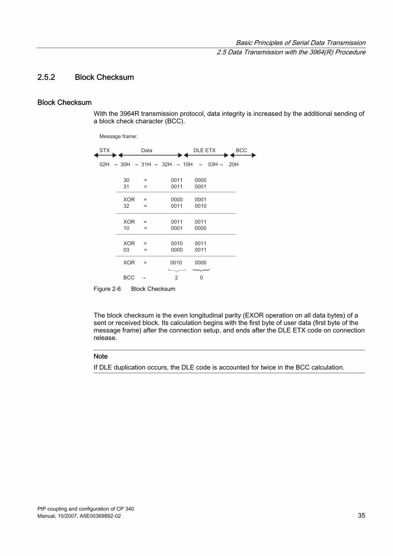
Block Checksum With the 3964R transmission protocol, data integrity is increased by the additional sending of a block check character (BCC).
Figure 2-6 Block Checksum
The block checksum is the even longitudinal parity (EXOR operation on all data bytes) of a sent or received block. Its calculation begins with the first byte of user data (first byte of the message frame) after the connection setup, and ends after the DLE ETX code on connection release.
Note If DLE duplication occurs, the DLE code is accounted for twice in the BCC calculation.

Basic Principles of Serial Data Transmission 2.5 Data Transmission with the 3964(R) Procedure
PtP coupling and configuration of CP 340 36 Manual, 10/2007, A5E00369892-02
2.5.3 Sending Data with 3964(R)
Process of Data Transmission when Sending The figure below illustrates the transmission sequence when data is sent with the 3964(R) procedure.
Figure 2-7 Data Traffic when Sending with the 3964(R) Procedure
Establishing a Send Connection To establish the connection, the 3964(R) procedure sends the control code STX. If the communication partner responds with the DLE code before the acknowledgment delay time expires, the procedure switches to send mode. If the communication partner answers with NAK or with any other control code (except for DLE), or the acknowledgment delay time expires without a response, the procedure repeats the connection setup. After the defined number of unsuccessful setup attempts, the procedure aborts the connection setup and sends the NAK code to the communication partner. The system program reports the error to the function block P_SEND (output parameter STATUS).
Sending Data If a connection is successfully established, the user data contained in the output buffer of the CP 340 is sent to the communication partner with the chosen transmission parameters. The partner monitors the times between incoming characters. The interval between two characters must not exceed the character delay time.
Basic Principles of Serial Data Transmission 2.5 Data Transmission with the 3964(R) Procedure
PtP coupling and configuration of CP 340 Manual, 10/2007, A5E00369892-02 37
Releasing a Send Connection If the communication partner sends the NAK control code during an active send operation, the procedure aborts its transmission of the block and tries again as described above. If a different code is sent, the procedure first waits for the character delay time to expire and then sends the NAK code to change the mode of the communication partner to idle. Then the procedure starts to send the data again with the connection setup STX. Once the contents of the buffer have been sent, the procedure adds the codes DLE, ETX and with the 3964R only the block checksum BCC as the end identifier, and waits for an acknowledgment code. If the communication partner sends the DLE code within the acknowledgment delay time, the data block has been received without errors. If the communication partner responds with NAK, any other code (except DLE), or a damaged code, or if the acknowledgment delay time expires without a response, the procedure starts to send the data again with the connection setup STX. After the defined number of attempts to send the data block, the procedure stops trying and sends an NAK to the communication partner. The system program reports the error to the function block P_SEND (output parameter STATUS).

Basic Principles of Serial Data Transmission 2.5 Data Transmission with the 3964(R) Procedure
PtP coupling and configuration of CP 340 38 Manual, 10/2007, A5E00369892-02
2.5.4 Receiving Data with 3964(R)
Process of Data Transmission when Receiving The figure below illustrates the transmission sequence when data is received with the 3964(R) procedure.
Figure 2-8 Data Traffic when Receiving with the 3964(R) Procedure
Establishing a Receive Connection In idle mode, when there is no send request to be processed, the procedure waits for the communication partner to establish the connection. If the idle procedure receives any control code except for STX or NAK, it waits for the character delay time to expire, then sends the code NAK.
receiving data If the procedure receives the STX code and an empty receive buffer is available, it responds with DLE. Incoming receive characters are now stored in the receive buffer. If two consecutive DLE codes are received, only one of these is stored in the receive buffer. After each receive character, the procedure waits out the character delay time for the next character. If this period expires before another character is received, an NAK is sent to the communication partner. The system program then reports the error to the function block P_RCV (output parameter STATUS). If no empty receive buffer is available during a connection setup with STX, a wait time of 400 ms is started. If there is still no empty receive buffer after this time has expired, the system program reports the error (error message in STATUS output of FB), and the procedure sends a NAK and returns to idle mode. Otherwise, the procedure sends a DLE and receives the data as described above.

Basic Principles of Serial Data Transmission 2.5 Data Transmission with the 3964(R) Procedure
PtP coupling and configuration of CP 340 Manual, 10/2007, A5E00369892-02 39
Releasing a Receive Connection If transmission errors occur during receiving (lost character, frame error, parity error, etc.), the procedure continues to receive until the connection is shut down, then an NAK is sent to the communication partner. A repetition is then expected. If the undamaged block still cannot be received after the number of repeat attempts defined on parameter assignment, or if the communication partner does not start the repetition within a block wait time of 4 seconds, the procedure aborts the receive operation. The system program then reports the error to the function block P_RCV (output parameter STATUS). When the 3964 procedure detects a DLE ETX character string, it ends the receiving operation and confirms the successfully received block by sending a DLE signal to the communication partner. When errors are found in the received data, it outputs a NAK signal to the communication partner. A repetition is then expected. If the CP 340 recognizes the string DLE ETX BCC, it stops receiving and compares the received block check character with the longitudinal parity calculated internally. If the BCC is correct and no other receive errors have occurred, the CP 340 sends the code DLE to the communication partner. If the BCC is correct and no other receive errors have occurred, the 3964R procedure sends a DLE and returns to idle mode. If the BCC is faulty or a different receiving error occurs, an NAK is sent to the communication partner. A repetition is then expected.
Note As soon as it is ready, the 3964(R) procedure sends a single NAK to the communication partner to set the latter to idle.
Basic Principles of Serial Data Transmission 2.5 Data Transmission with the 3964(R) Procedure
PtP coupling and configuration of CP 340 40 Manual, 10/2007, A5E00369892-02
2.5.5 Handling Errored Data
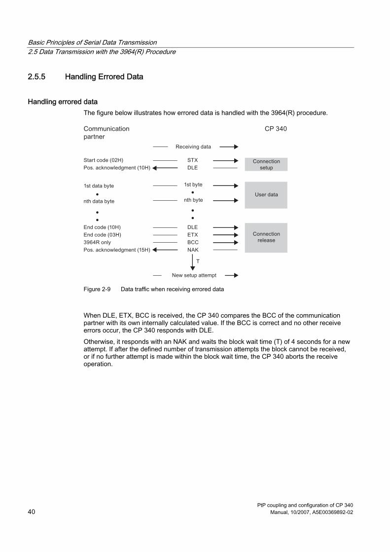
Handling errored data The figure below illustrates how errored data is handled with the 3964(R) procedure.
Figure 2-9 Data traffic when receiving errored data
When DLE, ETX, BCC is received, the CP 340 compares the BCC of the communication partner with its own internally calculated value. If the BCC is correct and no other receive errors occur, the CP 340 responds with DLE. Otherwise, it responds with an NAK and waits the block wait time (T) of 4 seconds for a new attempt. If after the defined number of transmission attempts the block cannot be received, or if no further attempt is made within the block wait time, the CP 340 aborts the receive operation.

Basic Principles of Serial Data Transmission 2.5 Data Transmission with the 3964(R) Procedure
PtP coupling and configuration of CP 340 Manual, 10/2007, A5E00369892-02 41
Initialization conflict The figure below illustrates the transmission sequence during an initialization conflict.
Figure 2-10 Data traffic during an initialization conflict
If a device responds to the communication partner's send request (code STX) within the acknowledgment delay time by sending the code STX instead of the acknowledgment DLE or NAK, an initialization conflict occurs. Both devices want to execute a send request. The device with the lower priority withdraws its send request and responds with the code DLE. The device with the higher priority sends its data in the manner described above. Once the connection has been terminated, the lower-priority device can execute its send request. To be able to resolve initialization conflicts you must parameterize different priorities for the communication partners.
Basic Principles of Serial Data Transmission 2.5 Data Transmission with the 3964(R) Procedure
PtP coupling and configuration of CP 340 42 Manual, 10/2007, A5E00369892-02
Procedure errors The procedure recognizes both errors caused by the communication partner and errors caused by faults on the line. In both cases, the procedure makes repeated attempts to send/receive the data block correctly. If this is not possible within the maximum number of repeat attempts set (or if a new error status occurs), the procedure aborts the send or receive process. It reports the error number of the first error detected and returns to idle state. These error messages are displayed in the STATUS output of the FB. If the system program frequently reports an error number at the STATUS output of the FB for send and receive repetitions, this implies occasional disturbances in data traffic. The high repetition frequency balances this out, however. In this case you are advised to check the transmission link for possible sources of interference, because frequent repetitions reduce the user-data rate and integrity of the transmission. The disturbance could also be caused, however, by a malfunction on the part of the communication partner. If the receive line is interrupted, the system program reports a BREAK status (a break is displayed via the diagnostic interrupt on the CP 340) and no repeat is started. The BREAK status in the STATUS output of the FB is automatically reset as soon as the connection is restored on the line. A BREAK evaluation occurs only if BREAK monitoring is not deactivated with the parameter assignment user interface. For every detected transmission error (lost character, frame or parity error), a standard number is reported, regardless of whether the error was detected during sending or receiving of a data block. The error is only reported, however, following unsuccessful repetitions.

Basic Principles of Serial Data Transmission 2.6 Data transfer using the ASCII driver
PtP coupling and configuration of CP 340 Manual, 10/2007, A5E00369892-02 43
2.6 Data transfer using the ASCII driver
2.6.1 RS 232C Secondary Signals
RS 232C accompanying signals The following RS 232C accompanying signals are available on the CP 340-RS 232C: ● DCD (input) Data Carrier Detect;
data carrier detected ● DTR (output) Data Terminal Ready;
CP 34x ready for operation ● DSR (input) Data Set Ready;
communication partner ready for operation ● RTS (output) Request To Send;
CP 34x ready to send ● CTS (input) Clear To Send;
communication partner can receive data from CP 34x (response to RTS = ON of the CP 34x)
● RI (input) Ring Indicator; ring indicator
When the CP 340-RS 232C is switched on, the output signals are in the OFF state (inactive). You can parameterize the use of the DTR/DSR and RTS/CTS control signals by means of the CP 340: Point-to-Point Communication, Parameter Assignment user interface or control them via functions (FCs) in the user program.
Using RS 232C accompanying signals The RS 232C accompanying signals can be used as follows: ● When automatic control of all RS 232C accompanying signals is configured ● When data flow control (RTS/CTS) is configured ● By means of the V24_STAT and V24_SET FCs
Note When automatic control of the RS 232C accompanying signals is configured, neither RTS/CTS data flow control nor RTS and DTR control by means of the V24_SET FC are possible. |When RTS/CTS data flow control is configured, RTS control by means of the V24_SET FC is not possible. On the other hand, it is always possible to read all RS 232C accompanying signals by means of the V24_STAT FC.
The sections that follow describe the basic principles for controlling and evaluating RS 232C accompanying signals.

Basic Principles of Serial Data Transmission 2.6 Data transfer using the ASCII driver
PtP coupling and configuration of CP 340 44 Manual, 10/2007, A5E00369892-02
Automatic control of accompanying signals Automatic control of RS 232C accompanying signals on the CP 340 is implemented as follows: ● As soon as the CP 340 is configured for operation in a mode with automatic control of the
RS 232C accompanying signals, it sets the RTS line to OFF and the DTR line to ON (CP 340 ready for operation).
This prevents the transfer of frames until the DTR line is set to ON. No data can be received at the RS 232C interface as long as DTR = OFF. Any send jobs will be cancelled with a corresponding error message. ● When a send job is pending, RTS is set to ON and the configured data output wait time
starts. When the data output time elapses and CTS = ON, the data is sent via the RS 232C interface.
● If the CTS line is not set to ON within the data output wait time or CTS changes to OFF during transfer, the module aborts the send job and generates an error message.
● Once the data has been sent and the configured clear RTS time has elapsed, the RTS line is set to OFF. CP 340 does not wait for a CTS transition to OFF.
● Data can be received via the RS 232C interface as soon as the DSR line is set to ON. If the CP 340's receive buffer is close to overflow, the CP 340 will not respond.
● An active send job or data receiving operation will be cancelled and an error message output if DSR changes from ON to OFF. The message "DSR = OFF (automatic control of V24 signals)" is entered in the diagnostic buffer of the CP 340.
Note When automatic control of the RS 232C accompanying signals is configured, neither RTS/CTS data flow control nor RTS and DTR control by means of the V24_SET FC are possible.

Basic Principles of Serial Data Transmission 2.6 Data transfer using the ASCII driver
PtP coupling and configuration of CP 340 Manual, 10/2007, A5E00369892-02 45
Timing diagram The figure illustrates the chronological sequence of a send job.
Figure 2-11 Timing diagram for automatic control of RS 232C accompanying signals
Data flow control/Handshaking Handshaking controls the data flow between two communication partners. Handshaking ensures that data is not lost in transmissions between devices that work at different speeds. There are essentially two types of handshaking: ● Software handshaking (e.g., XON/XOFF) ● Hardware handshaking (e.g., RTS/CTS)

Basic Principles of Serial Data Transmission 2.6 Data transfer using the ASCII driver
PtP coupling and configuration of CP 340 46 Manual, 10/2007, A5E00369892-02
Data flow control on the CP 340 is implemented as follows: ● As soon as the CP 340 is configured for operation in a mode with flow control, it sends
the XON character or sets the RTS line to ON. ● When the programmed number of frames or 50 characters are reached before the
receive buffer overflows (size of the receive buffer: 1,024 bytes), the CP 340 sends the XOFF character or sets the RTS line to OFF. If the communication partner ignores this state and continues transmission, an error message is generated if the receive buffer overflows. The data received in the last frame will be discarded.
● As soon as a frame is fetched by the S7 CPU and the receive buffer is ready to receive, the CP 340 sends the XON character or sets the RTS line to ON.
● The CP 340 interrupts transmission if it receives the XOFF character or when control signal CTS is set to OFF. If neither an XON character is received nor CTS is set to ON once a configured time has elapsed, transmission is aborted and an appropriate error message (0708H) is generated at the STATUS output of the function blocks.
Note When RTS/CTS data flow control is configured, you must fully wire the interface signals used in the plug connection (see Appendix B). |When RTS/CTS data flow control is configured, RTS control by means of the V24_SET FC is not possible.
Tasks of the V24_STAT/SET FC The V24_STAT function can be used to determine the status of each RS 232C accompanying signal. The V24_SET function can be used to control the DTR and RTS output signals.
Introduction The ASCII driver controls data transmission via a point-to-point connection between the CP 340 and a communication partner. This driver contains the physical layer (layer 1). The structure of the message frames is left open through the S7 user passing on the complete send message frame to the CP 340. For the receive direction, the end criterion of a message must be parameterized. The structure of the send message frames may differ from that of the receive message frames. The ASCII driver allows data of any structure (all printable ASCII characters as well as all other characters from 00 through FFH (with 8 data bit character frames) or from 00 through 7FH (with 7 data bit character frames)) to be sent and received.

Basic Principles of Serial Data Transmission 2.6 Data transfer using the ASCII driver
PtP coupling and configuration of CP 340 Manual, 10/2007, A5E00369892-02 47
2.6.2 Sending Data with the ASCII Driver
Sending When sending data, specify the number of bytes of user data to be transmitted as the "LEN" parameter when you call the P_SEND function block. The user data must contain any required start-of-text and end-of-text characters. If you are working with the end criterion "character delay time expired" when receiving data, the ASCII driver will pause between two frames, even when sending. You can call the P_SEND FB at any time, but the ASCII driver does not begin its output until a period longer than the parameterized character delay time has elapsed since the last frame was sent.
Note When XON/XOFF flow control is parameterized, the user data must not contain the parameterized XON or XOFF characters. The default settings are DC1 = 11H for XON and DC3 = 13H for XOFF.
Sending data The figure below illustrates a send operation.
Figure 2-12 Flowchart of a send operation

Basic Principles of Serial Data Transmission 2.6 Data transfer using the ASCII driver
PtP coupling and configuration of CP 340 48 Manual, 10/2007, A5E00369892-02
2.6.3 Receiving Data with the ASCII Driver
Selectable End Criteria For data transmission using the ASCII driver you can choose between three different end criteria. The end criterion defines when a complete message frame is received. The possible end criteria are as follows: ● Expiration of the character delay time
The message frame has neither a fixed length nor a defined end-of-text character; the end of the message is defined by a pause on the line (expiration of character delay time).
● On Receipt of End Character(s) The end of the message frame is marked by one or two defined end-of-text characters.
● On Receipt of Fixed Number of Characters The length of the receive message frames is always identical.
Code Transparency The code transparency of the procedure depends on the choice of parameterized end criterion and flow control: ● With one or two end-of-text characters
– not code-transparent ● When end criterion is character delay time or fixed message frame length
– code-transparent ● Code-transparent operation is not possible when the flow control XON/XOFF is used. Code-transparent means that any character combinations can occur in the user data without the end criterion being recognized.
Basic Principles of Serial Data Transmission 2.6 Data transfer using the ASCII driver
PtP coupling and configuration of CP 340 Manual, 10/2007, A5E00369892-02 49
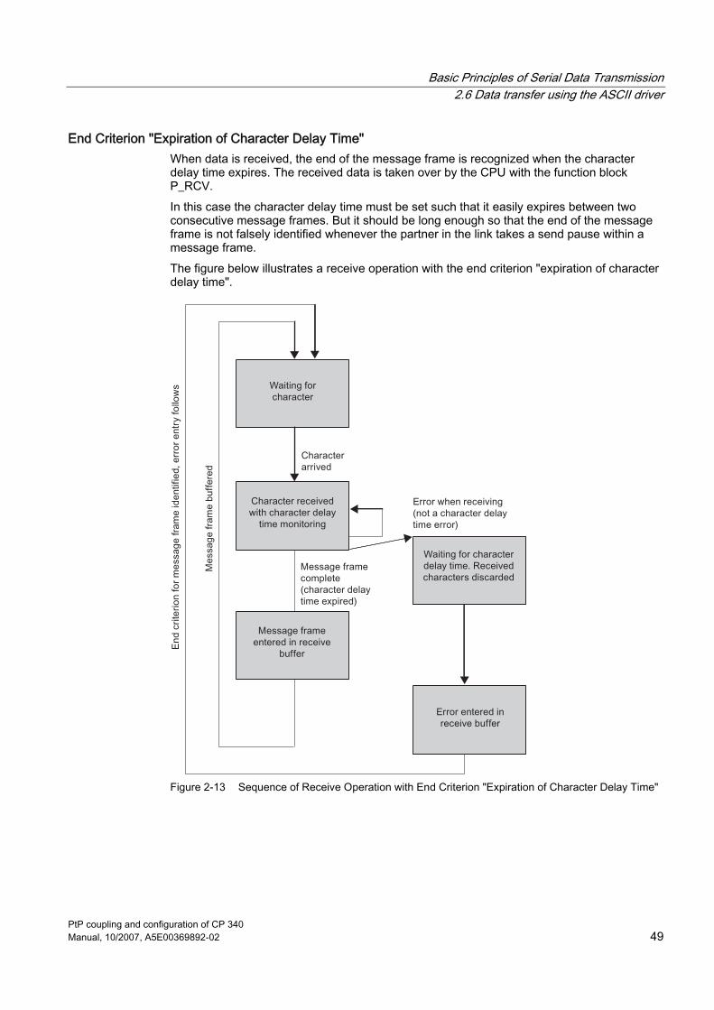
End Criterion "Expiration of Character Delay Time" When data is received, the end of the message frame is recognized when the character delay time expires. The received data is taken over by the CPU with the function block P_RCV. In this case the character delay time must be set such that it easily expires between two consecutive message frames. But it should be long enough so that the end of the message frame is not falsely identified whenever the partner in the link takes a send pause within a message frame. The figure below illustrates a receive operation with the end criterion "expiration of character delay time".
Figure 2-13 Sequence of Receive Operation with End Criterion "Expiration of Character Delay Time"

Basic Principles of Serial Data Transmission 2.6 Data transfer using the ASCII driver
PtP coupling and configuration of CP 340 50 Manual, 10/2007, A5E00369892-02
End Criterion End-of-Text Character When data is received, the end of the message frame is recognized when the parameterized end-of-text character(s) arrive. The received data, including the end-of-text character, is taken over by the CPU with the function block P_RCV. If the character delay time expires while the message frame is being received, the receive operation is terminated. An error message is issued and the message frame fragment is discarded. If you are working with end-of-text characters, transmission is not code-transparent, and you must make sure that the end code(s) do not appear in the user data of the user. The figure below illustrates a receive operation with the end criterion "end-of-text character".
Figure 2-14 Sequence of Receive Operation with End Criterion "End-of-Text Character"
Basic Principles of Serial Data Transmission 2.6 Data transfer using the ASCII driver
PtP coupling and configuration of CP 340 Manual, 10/2007, A5E00369892-02 51
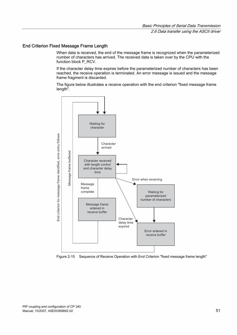
End Criterion Fixed Message Frame Length When data is received, the end of the message frame is recognized when the parameterized number of characters has arrived. The received data is taken over by the CPU with the function block P_RCV. If the character delay time expires before the parameterized number of characters has been reached, the receive operation is terminated. An error message is issued and the message frame fragment is discarded. The figure below illustrates a receive operation with the end criterion "fixed message frame length".
Figure 2-15 Sequence of Receive Operation with End Criterion "fixed message frame length"

Basic Principles of Serial Data Transmission 2.6 Data transfer using the ASCII driver
PtP coupling and configuration of CP 340 52 Manual, 10/2007, A5E00369892-02
2.6.4 BREAK - Monitoring on CP 340
BREAK evaluation A BREAK evaluation occurs only if the BREAK monitoring is not deactivated with the parameter assignment user interface.
2.6.5 Receive Buffer on CP 340
Receive buffer on CP 340 The CP 340 receive buffer accommodates 1,024 bytes. On parameterization, you can specify whether the CP receive buffer is to be deleted on startup and whether the overwriting of data in the receive buffer is to be prevented. You can also specify the range of values (1 to 250) for the number of buffered received frames.
The receive buffer on the CP 340 is a ring buffer: ● If multiple frames are written to the CP 340's receive buffer: The CP 340 always sends
the oldest frame to the CPU. ● If you only ever want to transfer the last frame received to the CPU, you must assign the
value "1" for the number of buffered frames and deactivate overwrite protection.
Note If continuous reading of received data is interrupted for a certain time in the user program and new received data are requested, the CP 340 might first receive an old frame before the latest frame received is sent to the CPU. The old frame is the frame which was en route between the CP 340 and the CPU at the time of the interruption, or the frame which had already been received by the FB.
See also Behavior of the CP 340 on Operating Mode Transitions of the CPU (Page 129)

Basic Principles of Serial Data Transmission 2.7 Parameterization Data
PtP coupling and configuration of CP 340 Manual, 10/2007, A5E00369892-02 53
2.7 Parameterization Data
Introduction By setting the basic parameter, you can define the diagnosis behavior of the CP 340. By selecting different protocols, you can adjust your CP 340 communications processor to suit the properties of the communication partner. The sections that follow describe the basic parameter of the CP 340 and the parameterization data for the 3964(R) procedure, ASCII driver and printer driver.
See also Sending Data with the ASCII Driver (Page 47)
2.7.1 Basic parameters of the CP 340
Introduction You can define in this parameter whether the CP 340 is to generate a diagnostics interrupt when fatal errors occur.
Basic Parameters Enter the basic parameter using the STEP 7 dialog "Properties - CP 340". Double-click on the CP 340 in the STEP 7 configuration table to open the dialog. The basic parameters are described in the table below.
Table 2-1 Basic Parameters
Parameters Description Range of values Default Value Interrupt generation The CP 340 can generate a diagnostics
interrupt if a fatal error is detected. • Yes • No
No

Basic Principles of Serial Data Transmission 2.7 Parameterization Data
PtP coupling and configuration of CP 340 54 Manual, 10/2007, A5E00369892-02
2.7.2 Parameterization Data of the 3964(R) Procedure
Introduction Using the parameterization data of the 3964(R) procedure, you can adjust the CP 340 to suit the properties of its communication partner.
Parameterization data of the 3964(R) procedure With the CP 340: Point-to-Point Communication, Parameter Assignment user interface, you can specify the parameters for the physical layer (layer 1) and for the data connection layer (layer 2) of the 3964(R) procedure. You will find a detailed description of the parameters below.
X27 (RS 422/485) interface Please note the following with reference to the X27 (RS 422/485) interface:
Note On the CP 340-RS 422/485 module variant, the 3694(R) procedure can only be used for RS 422.

Basic Principles of Serial Data Transmission 2.7 Parameterization Data
PtP coupling and configuration of CP 340 Manual, 10/2007, A5E00369892-02 55
Protocol The table below describes the protocol.
Table 2-2 3964(R) protocol
Parameter Description Default value with default values and no block check Default values are assigned to the
protocol parameters. If the CP 340 detects the string DLE ETX, it terminates reception and sends a DLE code to the communication partner if the block was received undamaged, or an NAK code if it was damaged.
R with default values and block check: Character delay time = 220 ms Acknowledgment delay time = 2,000 ms Connection retries = 6 Transmission retries = 6
R with default values and block check Default values are assigned to the protocol parameters. If the CP 340 detects the string DLE ETX BCC, it terminates reception. The CP 340 compares the block check character (BCC) received with the length parity calculated internally. If the BCC is correct and no other receive errors have occurred, the CP 340 sends the DLE code to the communication partner (the NAK code is sent if an error occurs).
Programmable without block check The values of the protocol parameters can be freely assigned by the user. If the CP 340 detects the string DLE ETX, it terminates reception and sends a DLE code to the communication partner if the block was received undamaged, or an NAK code if it was damaged.
R programmable with block check The values of the protocol parameters can be freely assigned by the user. If the CP 340 detects the string DLE ETX BCC, it terminates reception. The CP 340 compares the block check character (BCC) received with the length parity calculated internally. If the BCC is correct and no other receive errors have occurred, the CP 340 sends the DLE code to the communication partner (the NAK code is sent if an error occurs).

Basic Principles of Serial Data Transmission 2.7 Parameterization Data
PtP coupling and configuration of CP 340 56 Manual, 10/2007, A5E00369892-02
Protocol parameters You can only set the protocol parameters if you have not set the default values in the protocol.
Table 2-3 Protocol parameters (3964(R) procedure)
Parameter Description Range of values Default value Character delay time The character delay time defines the
maximum permissible time which may elapse between two received characters in a frame.
10 ms to 655,350 ms in 10 ms increments
20 ms
Acknowledgment delay time The acknowledgment delay time defines the maximum permissible time which may elapse before the partner's acknowledgment arrives during connection establishment (time between STX and partner's DLE acknowledgment) or termination (time between DLE ETX and partner's DLE acknowledgment).
10 ms to 655,350 ms in 10 ms increments
2,000 ms (550 ms for 3964 without block check)
Connection retries This parameter defines the maximum number of attempts the CP 340 is allowed in order to establish a connection.
1 to 255 6
Transmission retries The parameter defines the maximum number of attempts to transfer a frame (including the first one) in the event of errors.
1 to 255 6

Basic Principles of Serial Data Transmission 2.7 Parameterization Data
PtP coupling and configuration of CP 340 Manual, 10/2007, A5E00369892-02 57
Baud rate/Character frame The table below describes the baud rate/character frame.
Table 2-4 Baud rate/Character frame (3964(R) procedure)
Parameter Description Range of values Default value Baud rate Data transmission rate in bit/s • 2,400
• 4,800 • 9,600 • 19,200
9,600
Start bit During transmission, a start bit is prefixed to each character to be sent.
1 (fixed value) 1
Data bits Number of bits to which a character is mapped. • 7 • 8
8
Stop bits During transmission, the stop bits are appended to every character to be sent; this signals the end of a character.
• 1 • 2
1
Parity A sequence of information bits can be extended to include another bit, the parity bit. The addition of its value ("0" or "1") brings the value of all the bits up to a defined state. This improves data integrity. "None" indicates that no parity bit is sent. "Any" parity indicates that the CP has set the send parity to a value of "0". The parity bit is not checked when data is received.
• None • Odd • Even • Any
Even
Priority A partner has high priority if its send request takes precedence over the other partner's send request. A partner has low priority if its send request has to wait until the other partner's send request has been dealt with. With the 3964(R) procedure, you must configure both communication partners with different priorities, i.e., one partner is assigned high priority, the other low.
• Low • High
High
Activate BREAK monitoring
You can choose whether monitoring for an interrupted receive line should be activated or deactivated. If BREAK monitoring is deactivated, in the event of a BREAK • No entry will be made in the diagnostic buffer,
nor will the RECV FB be activated with set ERROR bit and corresponding STATUS entry
• Activated send jobs will be sent without an error message being generated for the user
• Yes • No
Depending on the HW variant used and the operating mode selected: • RS 232: Yes • TTY: Yes • RS 422 with
R(A)5V/R(B)0V: Yes (cannot be deactivated)
• RS 422 with R(A)0V/R(B)5V: No (cannot be activated)

Basic Principles of Serial Data Transmission 2.7 Parameterization Data
PtP coupling and configuration of CP 340 58 Manual, 10/2007, A5E00369892-02
Receive buffer on CP You will find a description of the parameters for the X27 (RS 422) interface in the table below.
Table 2-5 X27 (RS 422) interface (3964(R) procedure)
Parameter Description Range of values Default value Delete CP receive buffer on startup
You can specify whether the CP receive buffer should be deleted on startup or an existing (old) frame should be sent to the CPU.
• Yes • No
Yes
Receive line initial state R(A)5V/R(B)0V This initial state supports BREAK detection; it cannot be deactivated. R(A)0V/R(B)5V This initial state does not support break detection.
• R(A) 5V/R(B) 0V • R(A)0V/R(B)5V
R(A) 5V/R(B) 0V

Basic Principles of Serial Data Transmission 2.7 Parameterization Data
PtP coupling and configuration of CP 340 Manual, 10/2007, A5E00369892-02 59
2.7.3 Parameterization data of the ASCII driver
Introduction Using the parameterization data of the ASCII driver, you can adjust the communication processor to suit the properties of its communication partner.
Parameterization data of the ASCII driver Using the Point-to-Point Communication, Parameter Assignment user interface you specify the parameters for the physical layer (layer 1) of the ASCII driver. You will find a detailed description of the parameters below.
X27 (RS 422/485) interface Please note the following with reference to the X27 (RS 422/485) interface:
Note With the CP 340-RS 422/485 module variant, the ASCII driver can be used in four-wire mode (RS 422) and two-wire mode (RS 485). You must specify the type of interface required (RS 422 or RS 485) during parameter assignment.
Protocol parameters The table below describes the protocol parameters.
Table 2-6 Protocol parameters (ASCII driver)
Parameter Description Range of values Default value Indicator for end of received frame
Defines which criterion signals the end of each frame.
• Once character delay time has elapsed
• On receipt of end-of-text character(s)
• On receipt of a fixed number of characters
Once character delay time has elapsed
Character delay time The character delay time defines the maximum permissible time interval between 2 characters received consecutively.(1)
4 ms to 65,535 ms 4 ms
End-of-text character 1(2) First end code • 7 data bits: 0 to 7FH (hex)(3)
• 8 data bits: 0 to FFH (hex) (3)
3
End-of-text character 2(2) Second end code, if specified
• 7 data bits: 0 to 7FH (hex) (3)
• 8 data bits: 0 to FFH (hex) (3)
0

Basic Principles of Serial Data Transmission 2.7 Parameterization Data
PtP coupling and configuration of CP 340 60 Manual, 10/2007, A5E00369892-02
Parameter Description Range of values Default value Frame length when received(4)
If the end criterion is "fixed frame length", the number of bytes making up a frame is defined.
Up to 1,024 (bytes) 240
(1) The minimum character delay time is the time required to transfer 4 characters. (2) Can only be set if the end criterion is an end-of-text character. (3) Depending on whether you set 7 or 8 data bits for the character frame. (4) Can only be set if the end criterion is fixed frame length.
Baud rate/Character frame The table below contains descriptions of and specifies ranges of values for the relevant parameters.
Table 2-7 Baud rate/Character frame (ASCII driver)
Parameter Description Range of values Default value Baud rate Data transmission rate in bit/s.
Please note: The ASCII driver can be operated in full-duplex mode.
• 2,400 • 4,800 • 9,600
9,600
Start bit During transmission, a start bit is prefixed to each character to be sent.
• 1 (fixed value)
Data bits Number of bits to which a character is mapped.
• 7 • 8
8
Stop bits During transmission, the stop bits are appended to every character to be sent; this signals the end of a character.
• 1 • 2
1
Parity A sequence of information bits can be extended to include another bit, the parity bit. The addition of its value ("0" or "1") brings the value of all the bits up to a defined state. This improves data integrity. "None" indicates that no parity bit is sent. "Any" parity indicates that the CP 340 has set the send parity to a value of "0". Parity is not checked when data is received.
• None • Odd • Even • Any
Even
Depending on the HW variant used and the operating mode selected: RS 232: Yes TTY Yes RS 422 with R(A)5V/R(B)0V:
Yes (cannot be deactivated)
Activate BREAK monitoring
You can choose whether monitoring for an interrupted receive line should be activated or deactivated. If BREAK monitoring is deactivated, in the event of a BREAK: • No entry will be made in the diagnostic
buffer, nor will the RECV FB be activated with set ERROR bit and corresponding STATUS entry
• Yes • No
RS 422/RS 485 with R(A)0V/R(B)5V:
No (cannot be activated)

Basic Principles of Serial Data Transmission 2.7 Parameterization Data
PtP coupling and configuration of CP 340 Manual, 10/2007, A5E00369892-02 61
Parameter Description Range of values Default value • Activated send jobs will be sent without
an error message being generated for the user
With the RS 422 HW variant, this parameter is controlled implicitly via the initial state for the receive lines selected in the "Interface" folder.
Data flow control The table below contains a description of the parameters for data flow control. Data flow control is not possible with the RS 485 interface. Data flow control with "RTS/CTS" and "automatic control of V24 signals" is only supported on RS 232C interfaces.
Table 2-8 Data flow control (ASCII driver)
Parameter Description Range of values Default value Data flow control Defines which data flow
control procedure is used. • None • XON/XOFF • RTS/CTS • Automat. control of V24
signals
None
XON character (1) Code for XON character • 7 data bits: 0 to 7FH (hex) (2)
• 8 data bits: 0 to FFH (hex) (2)
(DC3)
XOFF character (1) Code for XOFF character • 7 data bits: 0 to 7FH (hex) (2)
• 8 data bits: 0 to FFH (hex) (2)
(DC3)
Waiting for XON after XOFF (wait time for CTS = ON) (3)
Period of time the CP 340 waits for the XON character or for CTS = "ON" from the communication partner when sending.
20 ms to 655,350 ms in 10 ms increments
20 ms
Clear RTS time (Only with automatic control of RS 232C accompanying signals)
Time to wait following transfer before the CP 340 sets the RTS line to OFF.
0 ms to 655,350 ms in 10 ms increments
0 ms
Data output wait time (Only with automatic control of RS 232C accompanying signals)
The time the CP 340 waits after setting the RTS line to ON for CTS = "ON" from the communication partner before it initiates the transfer.
0 ms to 655,350 ms in 10 ms increments
0 ms
(1) Only for data flow control with XON/XOFF. (2) Depending on whether you set 7 or 8 data bits for the character frame. (3) Only for data flow control with XON/XOFF or RTS/CTS.

Basic Principles of Serial Data Transmission 2.7 Parameterization Data
PtP coupling and configuration of CP 340 62 Manual, 10/2007, A5E00369892-02
Receive buffer on CP The table below describes the parameters for the CP receive buffer.
Table 2-9 Receive buffer on CP (ASCII driver)
Parameter Description Range of values Default value Delete CP receive buffer on startup (Where the buffering of multiple frames is concerned, CP 340 works in accordance with the FIFO principle when transferring frames to the CPU (ring buffer).)
You can specify whether the CP receive buffer should be deleted on startup or an existing (old) frame should be sent to the CPU.
• Yes • No
Yes
Buffered received frames (Where the buffering of multiple frames is concerned, CP 340 works in accordance with the FIFO principle when transferring frames to the CPU (ring buffer).)
You can specify the number of received frames to be buffered in the CP receive buffer. If you specify "1" here and deactivate the "Prevent overwriting" parameter and cyclically read the received data from the user program, a current frame will always be sent to the CPU.
1 to 250 250
Prevent overwriting You can deactivate this parameter if the "Buffered received frames" parameter is set to "1". This authorizes the overwriting of the buffered received frame.
• Yes • No (only if "Buffered
received frames" = "1")
Yes
X27 (RS 422/485) interface You will find a description of the parameters for the X27 (RS 422/485) interface in the table below.
Table 2-10 X27 (RS 422/485) interface (ASCII driver)
Parameter Description Range of values Default value Operating mode Specifies whether the X27
(RS 422/485) interface is to operate in full-duplex (RS 422) or half-duplex (RS 485) mode.
• Full-duplex (RS 422) four-wire mode
• Half-duplex (RS 485) two-wire mode
Full-duplex (RS 422) four-wire mode
Receive line initial state This initial state corresponds to idle state (no senders active) in "half-duplex (RS 485) two-wire mode".
• R(A) 5V/R(B) 0V • R(A) 0V/R(B) 5V
R(A) 5V/R(B) 0V

Basic Principles of Serial Data Transmission 2.7 Parameterization Data
PtP coupling and configuration of CP 340 Manual, 10/2007, A5E00369892-02 63
Receive line initial state The figure illustrates the wiring of the receiver at the X27 (RS 422/485) interface:
Figure 2-16 Wiring of the receiver at the X27 (RS 422/485) interface

Basic Principles of Serial Data Transmission 2.7 Parameterization Data
PtP coupling and configuration of CP 340 64 Manual, 10/2007, A5E00369892-02
2.7.4 Parameterization data of the printer driver
Introduction You can use the parameterization data of the printer driver to generate the transmission-specific parameters and the message texts for printout.
Parameterization data of the printer driver With the CP 340: Point-to-Point Communication, Parameter Assignment user interface, you can specify: ● The parameters for the physical layer (layer 1) of the printer driver ● The message texts for printout ● The page layout, character set and control characters for the message texts You will find a detailed description of the parameters below.
Baud rate/Character frame The table below contains descriptions of and specifies ranges of values for the relevant parameters.
Table 2-11 Baud rate/Character frame (printer driver)
Parameter Description Range of values Default value Baud rate Data transmission rate in bit/s • 2,400
• 4,800 • 9,600
9,600
Start bit During transmission, a start bit is prefixed to each character to be sent.
1 (fixed value)
1
Data bits Number of bits to which a character is mapped. • 7 • 8
8
Stop bits During transmission, the stop bits are appended to every character to be sent; this signals the end of a character.
• 1 • 2
1
Parity A sequence of information bits can be extended to include another bit, the parity bit. The addition of its value ("0" or "1") brings the value of all the bits up to a defined state. This improves data integrity. "None" indicates that no parity bit is sent. "Any" parity indicates that the CP 340 has set the send parity to a value of "0".
• None • Odd • Even • Any
Even
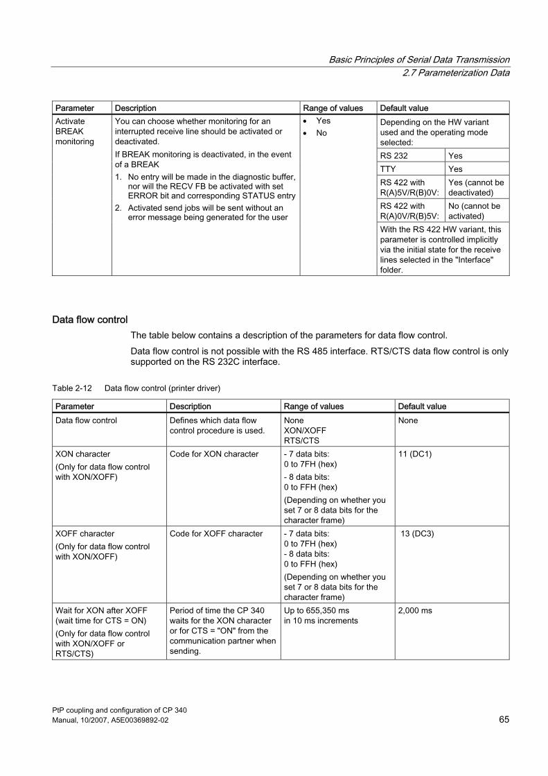
Basic Principles of Serial Data Transmission 2.7 Parameterization Data
PtP coupling and configuration of CP 340 Manual, 10/2007, A5E00369892-02 65
Parameter Description Range of values Default value Depending on the HW variant used and the operating mode selected: RS 232 Yes TTY Yes RS 422 with R(A)5V/R(B)0V:
Yes (cannot be deactivated)
RS 422 with R(A)0V/R(B)5V:
No (cannot be activated)
Activate BREAK monitoring
You can choose whether monitoring for an interrupted receive line should be activated or deactivated. If BREAK monitoring is deactivated, in the event of a BREAK 1. No entry will be made in the diagnostic buffer,
nor will the RECV FB be activated with set ERROR bit and corresponding STATUS entry
2. Activated send jobs will be sent without an error message being generated for the user
• Yes • No
With the RS 422 HW variant, this parameter is controlled implicitly via the initial state for the receive lines selected in the "Interface" folder.
Data flow control The table below contains a description of the parameters for data flow control. Data flow control is not possible with the RS 485 interface. RTS/CTS data flow control is only supported on the RS 232C interface.
Table 2-12 Data flow control (printer driver)
Parameter Description Range of values Default value Data flow control Defines which data flow
control procedure is used. None XON/XOFF RTS/CTS
None
XON character (Only for data flow control with XON/XOFF)
Code for XON character - 7 data bits: 0 to 7FH (hex) - 8 data bits: 0 to FFH (hex) (Depending on whether you set 7 or 8 data bits for the character frame)
11 (DC1)
XOFF character (Only for data flow control with XON/XOFF)
Code for XOFF character - 7 data bits: 0 to 7FH (hex) - 8 data bits: 0 to FFH (hex) (Depending on whether you set 7 or 8 data bits for the character frame)
13 (DC3)
Wait for XON after XOFF (wait time for CTS = ON) (Only for data flow control with XON/XOFF or RTS/CTS)
Period of time the CP 340 waits for the XON character or for CTS = "ON" from the communication partner when sending.
Up to 655,350 ms in 10 ms increments
2,000 ms

Basic Principles of Serial Data Transmission 2.7 Parameterization Data
PtP coupling and configuration of CP 340 66 Manual, 10/2007, A5E00369892-02
X27 (RS 422/485) interface You will find a description of the parameters for the X27 (RS 422/485) interface in the table below.
Table 2-13 X27 (RS 422/485) interface (ASCII driver)
Parameter Description Range of values Default value Receive line initial state R(A)5V/R(B)0V: This initial
state supports BREAK detection; it cannot be deactivated. R(A)0V/R(B)5V: This initial state does not support break detection.
R(A) 5V/R(B) 0V R(A) 0V/R(B) 5V
R(A) 5V/R(B) 0V
Page layout The table below contains a description of the parameters for the page layout.
Table 2-14 Page layout (printer driver)
Parameter Description Range of values Default value Left margin (number of characters)
Number of spaces to precede each line in the body of the text, header or footer. It is up to you to ensure that a line is not too long for the printer.
0 to 255 3
Lines per page (with header and footer)
Number of lines to be printed on each page. The number of lines printed is calculated on the basis of the separators output. In other words, all headers and footers must be counted.
1 to 255 0 (continuous printing)
50
Separators/ Line end
Characters concluding text, header and footer lines. The output text, header and footer must contain the defined separator.
- CR (carriage return) - LF (line feed) - CR LF (carriage return and line feed) - LF CR (line feed and carriage return)
CR LF (carriage return and line feed)

Basic Principles of Serial Data Transmission 2.7 Parameterization Data
PtP coupling and configuration of CP 340 Manual, 10/2007, A5E00369892-02 67
Parameter Description Range of values Default value Headers/Footers Text for up to two header
and footer lines; a header or footer line is output when the entry field in the parameter assignment software contains a text or at least a blank. If a text is specified only for the 2nd header or footer line, the 1st header or footer line is automatically padded with a blank and printed. A blank line is output before and after headers/footers.
- ASCII characters (text) - %P output conversion statement for page numbers) (max. 60 characters)
Character set The table below contains a description of the parameters for the character set.
Table 2-15 Character set (printer driver)
Parameter Description Range of values Default value Printer character set Set "IBM" to convert the set Windows ANSI character
set into the printer character set. Set "User-Defined" to adapt the character set to include special characters for a particular language.
• IBM • User-Defined
IBM
Control characters The table below contains a description of the parameters for control characters.
Table 2-16 Control characters (printer driver)
Parameter Description Range of values Default value Printer emulation Sets the printer emulation (printer commands for the
following control characters: bold, condensed, expanded, italics, and underlining). Set "User-Defined" to modify the printer emulation and include additional control characters. The characters A to Z and a to z are permissible as control characters.
• HP DeskJet • HP LaserJet • IBM Proprinter • User-Defined
HP DeskJet
Features Conditions for configuring message texts: ● Size of the text SDB: 8 KB ● Max. length of a message text without variables: 150 characters ● Max. length of a message text with variables displayed: 250 characters ● Max. number of variables per message text: 4 (3 + message text number)

Basic Principles of Serial Data Transmission 2.7 Parameterization Data
PtP coupling and configuration of CP 340 68 Manual, 10/2007, A5E00369892-02
Message texts The table below contains a description of the parameters for configuring message texts (using the CP 340: Point-to-Point Communication, Parameter Assignment user interface).
Table 2-17 Message texts (printer driver)
Parameter Description Range of values Default valueName of text SDB/text file The message texts for a CP 340
(serial interface) must be saved to a text SDB for parameter assignment. You can also save configured message texts to an external text file.
ASCII characters (max. 8 characters)
-
Version number Version number of the text SDB/text file
1 to 255.9 -
Message texts All the message texts stored in the text block are displayed here together with their message text numbers; you can use the "Edit message" parameter to change a selected message text line.
ASCII characters (unchangeable) -
Edit message You can transfer message texts edited here to the "Message Texts" list by clicking "Enter".
Message number: 0 to 99 Message text (max. 150 characters) • ASCII characters (text) • Conversion statements (for
variables) • Control characters (all those
defined in the control character table)
-
Font style You can easily assign control characters to selected text in the "Edit Message" entry field using buttons B to U.
• B (bold) • C (condensed) • E (expanded) • I (italic) • U (underlined)
-

Basic Principles of Serial Data Transmission 2.7 Parameterization Data
PtP coupling and configuration of CP 340 Manual, 10/2007, A5E00369892-02 69
2.7.5 Conversion and Control Statements for Printer Output
Introduction The output of a message text with variables and control statements (e.g., for bold, condensed, expanded, or italic type and underlining) is defined by means of a format string. In the format string you can also define statements to execute other useful functions for printout (e.g., to set a page number or start a new page). All the permissible characters and display types for the format string are described below. You can also configure all the described control statements (except \F "start new page" and \x "print without page break") and conversion statements for variables (except for %P "set page number") in the message texts using the CP 340: Point-to-Point Communication, Parameter Assignment user interface.
Format string The figure illustrates the structure of the format string schematically. A format string can contain normal text and/or conversion statements for variables and/or control statements. Normal text, conversion statements and control statements can occur in any sequence in the format string. There must be one (and only one) conversion statement for each variable in the format string or message text. The conversion statements are applied to the variables in the sequence in which they occur.
Figure 2-17 Schematic structure of the format string
Permissible characters for text The following can be specified as text: ● All printable characters ● All characters preceded by $ at the language interface (ICE 1131-3). The language
compilers convert these characters into the corresponding hex code. Exception: The character $N is not permitted. Example: Carriage return ODH = $R in the format string

Basic Principles of Serial Data Transmission 2.7 Parameterization Data
PtP coupling and configuration of CP 340 70 Manual, 10/2007, A5E00369892-02
Conversion statement The figure illustrates the structure of a conversion statement schematically.
Figure 2-18 Schematic structure of a conversion statement
Flag
Without
= Right-justified output
– = Left-justified output
Width
Without
= Output in the default display
N = Exactly n characters are output (up to 255 characters are possible); blanks may be added before (right-justified output) or after (left-justified output).
Precision Precision is only relevant to display types A, D, F, and R. It is ignored otherwise.
Without
= Output in the default display
.0 = No output of decimal points or decimal positions in real (R) and floating point (F) display types.
.n = Output of decimal point and n (1 to 99) significant decimal positions in real (R) and floating point (F) display types. In the case of dates (= display types A and D), precision relates to the number of digits used for the year. Only 2 and 4 are permitted for dates.
Please note that the precision is always preceded by a period. The period serves to identify it and separate it from the width.
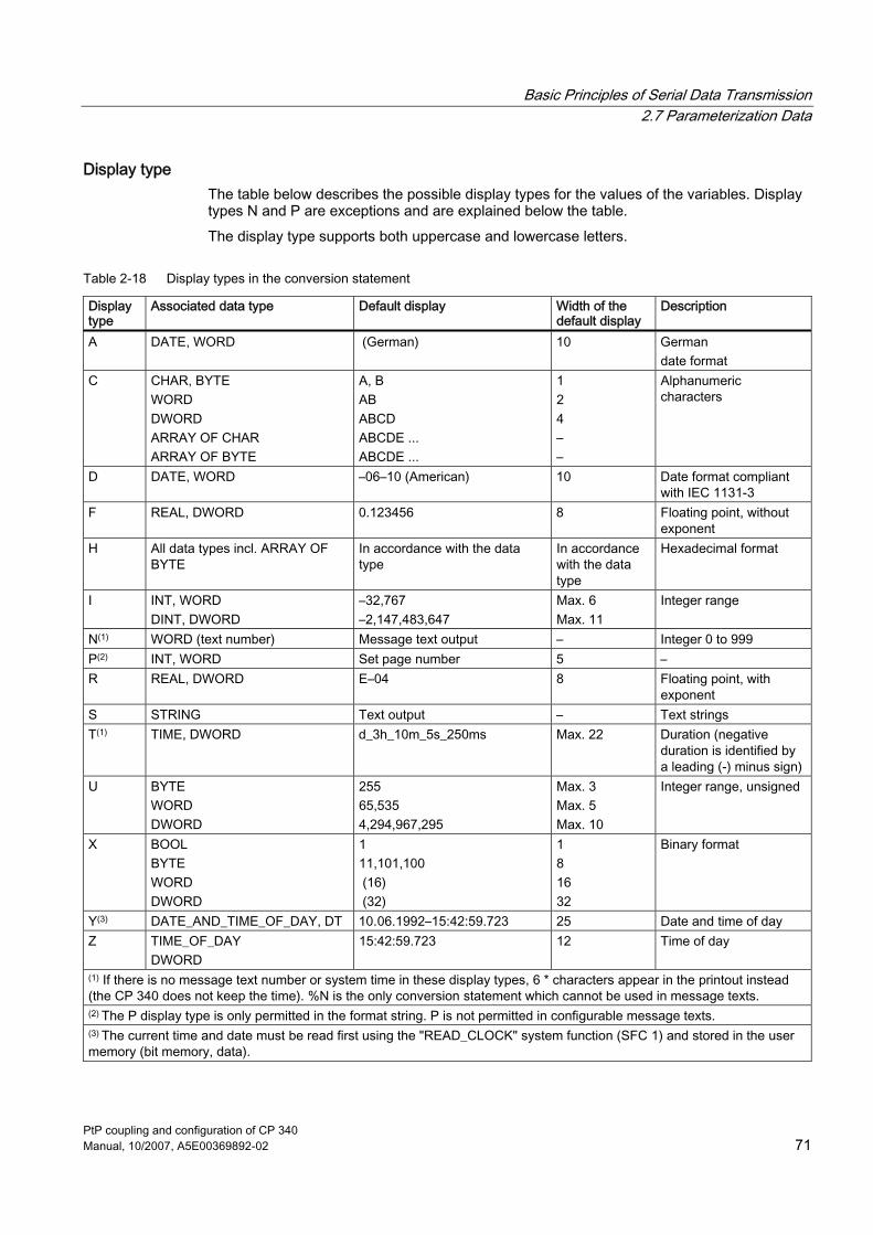
Basic Principles of Serial Data Transmission 2.7 Parameterization Data
PtP coupling and configuration of CP 340 Manual, 10/2007, A5E00369892-02 71
Display type The table below describes the possible display types for the values of the variables. Display types N and P are exceptions and are explained below the table. The display type supports both uppercase and lowercase letters.
Table 2-18 Display types in the conversion statement
Display type
Associated data type Default display Width of the default display
Description
A DATE, WORD (German) 10 German date format
C CHAR, BYTE WORD DWORD ARRAY OF CHAR ARRAY OF BYTE
A, B AB ABCD ABCDE ... ABCDE ...
1 2 4 – –
Alphanumeric characters
D DATE, WORD –06–10 (American) 10 Date format compliant with IEC 1131-3
F REAL, DWORD 0.123456 8 Floating point, without exponent
H All data types incl. ARRAY OF BYTE
In accordance with the data type
In accordance with the data type
Hexadecimal format
I INT, WORD DINT, DWORD
–32,767 –2,147,483,647
Max. 6 Max. 11
Integer range
N(1) WORD (text number) Message text output – Integer 0 to 999 P(2) INT, WORD Set page number 5 – R REAL, DWORD E–04 8 Floating point, with
exponent S STRING Text output – Text strings T(1) TIME, DWORD d_3h_10m_5s_250ms Max. 22 Duration (negative
duration is identified by a leading (-) minus sign)
U BYTE WORD DWORD
255 65,535 4,294,967,295
Max. 3 Max. 5 Max. 10
Integer range, unsigned
X BOOL BYTE WORD DWORD
1 11,101,100 (16) (32)
1 8 16 32
Binary format
Y(3) DATE_AND_TIME_OF_DAY, DT 10.06.1992–15:42:59.723 25 Date and time of day Z TIME_OF_DAY
DWORD 15:42:59.723 12 Time of day
(1) If there is no message text number or system time in these display types, 6 * characters appear in the printout instead (the CP 340 does not keep the time). %N is the only conversion statement which cannot be used in message texts. (2) The P display type is only permitted in the format string. P is not permitted in configurable message texts. (3) The current time and date must be read first using the "READ_CLOCK" system function (SFC 1) and stored in the user memory (bit memory, data).
Basic Principles of Serial Data Transmission 2.7 Parameterization Data
PtP coupling and configuration of CP 340 72 Manual, 10/2007, A5E00369892-02
Output by means of message text number (%N) Use the N display type to start printing message texts stored on the CP 340. The conversion statement variable contains the number of the message text. Example: The pressure in the chamber "is falling"
Format string = %N %S Variable 1 = 17 (message text no. 17: The pressure in the chamber ...) Variable 2 = reference to string (string variable: ... is falling)
Note All conversion statements except for %N and all control statements except for "\F" and "\x" can be used in message texts. An explicit width setting of %N limits the printed length of the referenced message text to the width indicated.
Setting the page number (%P) Use the P display type to change the page number in the printout. The CP 340 always begins a printout at page 1. This conversion statement allows you to set the page number to a specific value. The conversion statement variable contains the number to be set. Example: (Setting the page number to 10)
Format string
= %P
Variable 1 = 10 (page number: 10)
Note In the case of the P display type, there must be no further text, conversion or control statements in the format string. The P display type is not permitted in configured message texts.

Basic Principles of Serial Data Transmission 2.7 Parameterization Data
PtP coupling and configuration of CP 340 Manual, 10/2007, A5E00369892-02 73
Notes about conversion statements Please note the following in relation to conversion statements: ● Whenever a maximum length is specified for the default display, the actual output can
also be shorter. Example: The output of the integer 10 consists of only 2 characters. ● The length of the data to be printed depends on the length of the variables. For example,
in the case of the I display type a maximum of 6 characters can be output for the INT data type and a maximum of 11 characters for the DINT data type.
● A width of "0" is not permissible in conversion statements. This is printed out as "******" with the valid conversion statement.
● If the specified width is too small, in the case of text-based output (display types A, C, D, S, T, Y, and Z), only the number of characters corresponding to the specified width are output (the output is truncated). In all other cases, * characters are output corresponding to the width.
● Undefined or invalid conversion statements are not executed. This is printed out as "******" (e.g., display type missing: %2.2). The rest of the conversion statement (i.e., everything after the character identified as incorrect) is output. This allows the exact cause of the error to be determined.
● Conversion statements without associated variables will be ignored. Variables for which there is no conversion statement are not output.
● Conversion statements that are not supported in a header or footer are not executed. Instead, they are forwarded to the printer transparently.
● You must use control statements to specify formatting (line feed, tabs, etc.) in a message text or in the printout of a long conversion statement.
● If both the format string and the message text contain conversion statements, the format string is expanded first, followed by the message text. Example: Voltage 3 V – Current 2 A Message text 1 = Voltage %I V Format string = "%N – Current: %I A" Variable 1 = 1 Variable 2 = 2 Variable 3 = 3
Examples of invalid conversion statements Below are several examples of invalid conversion statements. Example 1: ******.2R Format string = %303.2R Variable 1 = 1.2345E6 Error: Invalid width in the R display type. The maximum permissible value for all display types is 255.

Basic Principles of Serial Data Transmission 2.7 Parameterization Data
PtP coupling and configuration of CP 340 74 Manual, 10/2007, A5E00369892-02
Example 2: **** Format string = %4.1I Variable 1 = 12,345 DEC Error: The selected width was too small for the variable value to be output. The precision is not relevant to display type I. Example 3: 96–10–3 Format string = %7.2D Variable 1 = D#1996–10–31 Error: The format string is formally correct, but the selected width was too small to print the date in full. Example 4: ********** Format string = %.3A Variable 1 = D#1996–10–31 Error: The default width of display type A was selected but with invalid precision. The possible values here are 2 and 4. Example 5: ****** Format string = %3.3 Variable 1 = 12,345 HEX Error: A display type was not specified.
Examples of correct conversion statements Below are some examples of correct conversion statements: Example 1: .....31.10.1996 Format string = %15.4A Variable 1 = D#1996–10–31 A width of 15 with a precision of 4 (width of the year) and right-justified formatting were selected. Example 2: 12345. Format string = %–6I Variable 1 = 12,345 DEC The selected width was one character greater than the variable value to be output; left-justified formatting. Example 3: 12d_0h_0m_23s_348ms Format string = %T Variable 1 = T#12D23S348MS The IEC time is in the standard format; unspecified time units are inserted with zeros. Example 4: 1.234560E+02 Format string = %12.6R Variable 1 = 123.456

Basic Principles of Serial Data Transmission 2.7 Parameterization Data
PtP coupling and configuration of CP 340 Manual, 10/2007, A5E00369892-02 75
A width of 12 is available to display the whole variable, with the precision (number of decimal positions) taking up 6 characters. Example 5: TEST.. Format string = %–6C Variable 1 = TEST Left-justified formatting of the text variables
Control statements Control statements are used to achieve specific results in the printout (e.g., underlining). In addition to the standard control statements (for bold, condensed, expanded, or italic type and underlining), you can also use other control characters if you enter them in the control character table on the CP 340: Point-to-Point Communication, Parameter Assignment user interface before parameterizing the CP 340. The figure illustrates the structure of the control statement schematically.
Figure 2-19 Schematic structure of control statements

Basic Principles of Serial Data Transmission 2.7 Parameterization Data
PtP coupling and configuration of CP 340 76 Manual, 10/2007, A5E00369892-02
Examples Below are some examples with control statements: Example 1: To output a text with "bold" and "underlining" on the printer, make the following entries: \BBold type\-B and \UUnderlining\-U are ways of highlighting a text. Example 2: To output the format string with the conversion statement "Message text no. %i of %8.2A" transparently on the printer, make the following entries: 'Message text no. \%i of \%8.2A'
Starting a new page (\F) Given the configured page layout, i.e., the configured headers and footers and the number of lines per page, the \F control statement can be used to start a new page. This differs from a pure form feed on the printer. Example: (Starting a new page) Format string = \F
Note In the case of the \F control statement, there must be no further text, conversion or control statements in the format string. The variables remain unassigned.
Printing without a line break (\x) The CP 340 normally appends the configured end-of-line character (CR, LF, CR LF, LF CR) when it sends a message text. The \x control statement cancels the line break after a message text. This means that you can print several message texts in a single line in order, for example, to display more variables in a line. The \x control statement is appended at the end of the format string. Example: The level "200" l was reached at "17.30" hours. ... Format string = The level %i l was reached at %Z hours.\x Variable 1 = time Variable 2 = level
Note Please note that when you use the \x control statement, the new line always begins without a left margin.

Basic Principles of Serial Data Transmission 2.7 Parameterization Data
PtP coupling and configuration of CP 340 Manual, 10/2007, A5E00369892-02 77
Notes about control statements Please note the following in relation to control statements: ● If the deactivation of an effect is requested without it previously having been activated, or
if the output device is incapable of producing the effect, the control statement is ignored. ● The % and \ characters required to define the format string can be printed by means of
the control statement. ● Undefined or invalid control statements are not executed.

Basic Principles of Serial Data Transmission 2.7 Parameterization Data
PtP coupling and configuration of CP 340 78 Manual, 10/2007, A5E00369892-02

PtP coupling and configuration of CP 340 Manual, 10/2007, A5E00369892-02 79
Starting up the CP 340 3Step sequence
Before starting up the CP 340 you will need to perform the following operations in the order given. 1. Install the communication processor 2. Configure the communication processor 3. Assign the communication processor parameters 4. Back up parameterization data 5. Create a user program for the CP
Installing the communication processor Installation of the CP comprises the integration of the CP into the rack of your automation system.
Configuring the communication processor The CP configuration includes its entry in the configuration table. Configure your CP using STEP 7 software.
Assigning the communication processor parameters Parameterizing the CP involves creating the specific parameters of the protocols and configuring message texts for printout. Configure the CP using the Point–to–Point Communication, Parameter Assignment user interface.
Backing up parameterization data A backup of CP parameterization data includes the storage of parameters, their download to the CPU and transfer to the CP. Back up your parameterization data using STEP 7 software.
Creating a user program for the CP CP programming includes the connection of the CP to the associated CPU using the STEP 7 user program. Program your CP using the language editors of the STEP 7 software.

Starting up the CP 340
PtP coupling and configuration of CP 340 80 Manual, 10/2007, A5E00369892-02
Further information For detailed information about CP programming, refer to the chapter of this manual titled "Configuring the CP 340". For detailed information about CP parameters, refer to the chapter of this manual titled "Configuring the communication protocols". For detailed information on backing up parameterization data, refer to the chapter of this manual titled "Managing the parameter data". For detailed information on CP installation, refer to the chapter of this manual titled "Installing the CP 340". A comprehensive programming example is available in the chapter titled "Programming example for standard blocks". A detailed description of programming with STEP 7 is contained in the STEP 7 manual.
See also Configuring the CP 340 (Page 88) Communication via Function Blocks (Page 98)
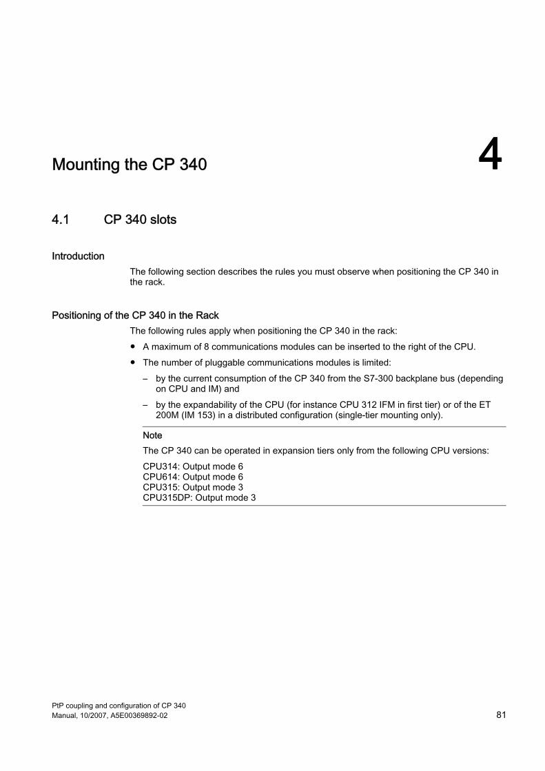
PtP coupling and configuration of CP 340 Manual, 10/2007, A5E00369892-02 81
Mounting the CP 340 44.1 CP 340 slots
Introduction The following section describes the rules you must observe when positioning the CP 340 in the rack.
Positioning of the CP 340 in the Rack The following rules apply when positioning the CP 340 in the rack: ● A maximum of 8 communications modules can be inserted to the right of the CPU. ● The number of pluggable communications modules is limited:
– by the current consumption of the CP 340 from the S7-300 backplane bus (depending on CPU and IM) and
– by the expandability of the CPU (for instance CPU 312 IFM in first tier) or of the ET 200M (IM 153) in a distributed configuration (single-tier mounting only).
Note The CP 340 can be operated in expansion tiers only from the following CPU versions: CPU314: Output mode 6 CPU614: Output mode 6 CPU315: Output mode 3 CPU315DP: Output mode 3

Mounting the CP 340 4.2 Installing and removing the CP 340
PtP coupling and configuration of CP 340 82 Manual, 10/2007, A5E00369892-02
4.2 Installing and removing the CP 340
Introduction When mounting and dismounting the CP 340, you must observe certain rules.
Tool For mounting and dismounting the CP 340 you require a 4.5 mm cylindrical screwdriver.
Note Before you mount or dismount the CP 340, you must switch the CPU to STOP mode. The power supply module does not need to be in POWER OFF mode. You can plug in or unplug the cable to the integrated submodule on the CP 340 at any time. However, you must make sure that no data are being transmitted at the integrated interface when you do so, otherwise data may be lost.
4.2.1 Installation steps
How to install the CP 340 in a rack To insert the CP 340 in a rack, proceed as follows: 1. Switch the CPU to STOP mode. 2. A bus connector is supplied with the CP 340. Plug this connector onto the backplane
connector of the module to the left of the CP 340. 3. If more modules are to be mounted to the right of the CP 340, plug the expansion bus of
the next module onto the right backplane connector of the CP 340. 4. Mount the CP 340 on the rail and tilt it downward. 5. Screw the CP 340 tight.

Mounting the CP 340 4.2 Installing and removing the CP 340
PtP coupling and configuration of CP 340 Manual, 10/2007, A5E00369892-02 83
4.2.2 Removal steps
To remove the CP 340 To dismount the CP 340 from the rack, proceed as follows: 1. Switch the CPU to STOP mode. 2. Open the front panel doors. 3. Detach the sub D connector from the integrated interface. 4. Undo the fastening screw on the module. 5. Swing the module off the rail, then take it out of the PLC.

Mounting the CP 340 4.2 Installing and removing the CP 340
PtP coupling and configuration of CP 340 84 Manual, 10/2007, A5E00369892-02

PtP coupling and configuration of CP 340 Manual, 10/2007, A5E00369892-02 85
Configuring and Parameterizing the CP 340 55.1 Parameterization Options
Configuration options You configure and parameterize the module variants of the CP 340 using STEP 7 or the CP 340: Point-to-Point Communication, Parameter Assignment user interface.
Table 5-1 Configuration options for the CP 340
Product Order number Configurable using the parameter assignment user interface
Under STEP 7
CP 340–RS 232C 6ES7 340–1AH00–0AE0* As of V1.0 As of V2.1 CP 340–RS 232C 6ES7 340–1AH01–0AE0** CP 340–20mA-TTY 6ES7 340–1BH00–0AE0** CP 340–RS 422/485 6ES7 340–1CH00–0AE0** CP 340-RS 232C 6ES7 340-1AH02-0AE0*** CP 340-20mA-TTY 6ES7 340-1BH02-0AE0*** CP 340-RS 422/485 6ES7 340-1CH02-0AE0***
As of V3.0 As of V3.0
* You can also use the parameter assignment user interface as of V3.0 to configure this module, although you will then only be able to parameterize the drivers integrated into the module firmware (not the printer drivers). ** You can also use the parameter assignment user interface as of V1.0 to configure these modules, although you will then only be able to parameterize the drivers available on the parameter assignment user interface (not the printer drivers). *** The new functionalities (FW update and ID data (read)) are only supported as of STEP 7 V5.2.

Configuring and Parameterizing the CP 340 5.2 Parameterizing the Communications Protocols
PtP coupling and configuration of CP 340 86 Manual, 10/2007, A5E00369892-02
5.2 Parameterizing the Communications Protocols
Introduction Once you have entered the CP 340 in the configuration table, you must supply its interface with parameters. In the case of the printer driver, you can also configure message texts for printer output. This process is known as "parameterization".
5.2.1 Parameterization of the CP 340
Prerequisite The parameter assignment user interface CP 340: Point-to-Point Communication, Parameter Assignment is installed on the PG/PC under STEP 7.
Parameter assignment The expression "parameter assignment" is used in the following to describe the setting of protocol-specific parameters and the configuration of message texts. This is done using the CP 340: Point-to-Point Communication, Parameter Assignment user interface. Double-click the CP 340 in the STEP 7 configuration table or highlight the CP 340 and select menu command Edit > Object Properties. The "Properties – CP 340" dialog will appear. This is where you can set the basic parameters of the CP 340. Click "Parameters" to launch the CP 340: Point-to-Point Communication, Parameter Assignment user interface.
See also Basic parameters of the CP 340 (Page 53)

Configuring and Parameterizing the CP 340 5.2 Parameterizing the Communications Protocols
PtP coupling and configuration of CP 340 Manual, 10/2007, A5E00369892-02 87
5.2.2 Installing the engineering tool
Installation The CP 340: Point-to-Point Communication, Parameter Assignment user interface is stored on a 3.5" floppy disk along with the function blocks and programming example. To install the parameter assignment user interface: 1. Insert the floppy disk into the floppy disk drive on your programming device/PC. 2. Under Windows 95 launch the dialog for installing software by double-clicking the
"Software" icon in the "Control Panel". 3. Select the floppy disk drive from the dialog window and run the Setup.exe file to start the
installation procedure. 4. Follow the on-screen instructions provided by the setup program.
Further information? The basic operation of the Point-to-Point Communication, Parameter Assignment user interface is the same for all communication processors and is self-explanatory. For this reason, the parameter assignment user interface is not described in detail here. Also, the online help provides sufficient support for working with the parameter assignment user interface.

Configuring and Parameterizing the CP 340 5.3 Configuring the CP 340
PtP coupling and configuration of CP 340 88 Manual, 10/2007, A5E00369892-02
5.3 Configuring the CP 340
Introduction Once you have mounted the CP 340 you must inform the programmable controller that it is there. This process is known as "configuration".
Prerequisite Before you can enter the CP 340 in the configuration table of the STEP 7 software, you must have created a project and a terminal with STEP 7.
Configuration In the following, "configuration" refers to the entry of the communications processor in the configuration table of the STEP 7 software. In the configuration table, enter the rack, the slot and the order number of the communications processor. STEP 7 then automatically assigns an address to the CP. The CPU is now able to find the communications processor in its slot in the rack by way of its address.

Configuring and Parameterizing the CP 340 5.4 Managing the Parameter Data
PtP coupling and configuration of CP 340 Manual, 10/2007, A5E00369892-02 89
5.4 Managing the Parameter Data
Introduction The configuration and parameterization data of the communication processor is stored in the current project (on the hard disk of the programming device/PC).
Data management When you quit the configuration table by selecting the menu command Station > Save or Station > Save As, the system automatically saves the configuration and parameterization data (including the module parameters) to the project/user file you have created.
Downloading the configuration and parameters You can now download the configuration and parameterization data online from the programming device to the CPU (menu command PLC > Download). The CPU accepts the parameters immediately after the download. The module parameters are automatically transmitted to the communication processor ● When they are downloaded onto the CPU and as soon as the communication processor
can be reached via the S7-300 backplane bus or
● When the CPU's operating mode changes from STOP to RUN (CPU startup). Unchanged parameters have the default value.
Further information The STEP 7 manual Configuring Hardware and Communication Connections With STEP 7 describes in detail how to ● Save the configuration and the parameters ● Download the configuration and the parameters to the CPU ● Read, modify, copy, and print the configuration and the parameters. ● You will find more information on the parameters in the chapter titled "Parameterization
data".

Configuring and Parameterizing the CP 340 5.5 Identification data
PtP coupling and configuration of CP 340 90 Manual, 10/2007, A5E00369892-02
5.5 Identification data
Definition Identification data represent information stored on the module and support you in: ● Troubleshooting a plant ● Verifying your plant configuration ● Locating hardware modifications in a plant This ID data allows the unambiguous identification of modules in online mode. Starting with order no. 6ES7 340–1xH02–0AE0, this data is available on the CP 340. To view the identification data, select PLC > Module Information, or Read Data Record (see below).
Reading the identification data Users can access specific ID data by selecting Read Data Record. The element of the ID data which is assigned to the corresponding index is found under the associated data record number. All data records which contain ID data have a length of 64 bytes. The table below shows the structure of those data records.
Table 5-2 Data record structure
Content Length (bytes) Coding (hex) Header information SZL ID 2 F1 11 Index 2 00 0x Length of identification data 2 00 38 Number of blocks which contain ID data 2 00 01
Table 5-3 Identification data
Identification data Index 2 00 0x Identification data associated with the relevant index
54

Configuring and Parameterizing the CP 340 5.5 Identification data
PtP coupling and configuration of CP 340 Manual, 10/2007, A5E00369892-02 91
Identification data of the CP 340 module
Table 5-4 Identification data of the CP 340 module
Identification data Access Default setting Description Index 1 (data record 231/read only) Manufacturer Read
(2 bytes) 00 2A hex (= 42 dec) The name of the manufacturer is saved to this
parameter (42 dec = Siemens AG).
Device name Read (20 bytes)
6ES7 340–1xH02–0AE0 Order number of the module x = A(RS232), B(TTY), C(RS422/485)
Device serial number Read (16 bytes)
The serial number of the module is saved to this parameter. This structure allows the unique identification of the module.
Hardware revision Read (2 bytes)
Provides information about the product version of the module.
Software revision Read (4 bytes)
Provides information about the firmware version of the module.
Statistical revision no.
Read (2 bytes)
- Not supported
Profile_ID Read (2 bytes)
F6 00 hex Internal parameter (to PROFIBUS DP)
Profile–specific type Read (2 bytes)
00 04 hex (= 4 dec) Internal parameter (communication module, to PROFIBUS DP)
I&M version Read (2 bytes)
00 00 hex (= 0 dec) Internal parameter (to PROFIBUS DP)
I&M supported Read (2 bytes)
00 01 hex (= 1 dec) Internal parameter (I&M0 and I&M1, to PROFIBUS DP)
Index 2 (data record 232/read and write) HID Read/
write (max. 32 characters)
- Plant (higher-level) designation of the module.
LD Read/ write (max. 22 characters)
- Location designation of the module.

Configuring and Parameterizing the CP 340 5.6 Download of firmware updates
PtP coupling and configuration of CP 340 92 Manual, 10/2007, A5E00369892-02
5.6 Download of firmware updates
Introduction You can enhance functionality and eliminate errors by downloading firmware updates to the CP 340 system memory. Download the firmware update using HW Config.
Basic firmware A CP 340 is supplied with basic firmware.
Prerequisites Prerequisites for downloading firmware updates: ● The CP 340 must be available online on the PG/PC. ● The new firmware version files must be available on your PG/PC file system.
Downloading firmware To update the firmware: 1. Open HW Config, then select the relevant CP 340 module. 2. Select the menu command PLC > Update Firmware. For further information on procedures, refer to the STEP 7 online help. The system outputs a message to indicate successful completion of the update and immediately enables the new firmware. After you have completed the CP 340 firmware update, attach a new label showing the new firmware version.
Note Switch the CPU to STOP before you download the module firmware file for the CP 340.
Update not completed successfully The module's red SF LED flashes if the update was not successful. Repeat the update. Contact your local Siemens representative if the update fails.

Configuring and Parameterizing the CP 340 5.6 Download of firmware updates
PtP coupling and configuration of CP 340 Manual, 10/2007, A5E00369892-02 93
LED display elements LED display elements when the FW update operation is active:
Table 5-5 LED display elements during the FW update
Status SF TXD RXD Remark To correct or avoid errors
FW update in progress On On On - - FW update completed On Off Off - - CP 340 without module firmware
Flashes (2 Hz)
Off Off Module firmware deleted, firmware update was cancelled, firmware update still possible
Reloading the firmware
Hardware error during firmware update
Flashes (2 Hz)
Flashes (2 Hz)
Flashes (2 Hz)
Delete/write operation failed
Switch module power off and on and try to download the firmware again. Check whether the module is defective.
Viewing the HW and FW versions To view the current hardware and firmware version of the CP 340, open STEP 7 and select the Module Information dialog box. You can open this dialog box by: In the SIMATIC Manager, selecting: File > Open > Project > Open HW Config > Station > Open Online > and double-clicking the CP 340 module.

Configuring and Parameterizing the CP 340 5.6 Download of firmware updates
PtP coupling and configuration of CP 340 94 Manual, 10/2007, A5E00369892-02

PtP coupling and configuration of CP 340 Manual, 10/2007, A5E00369892-02 95
Communication using function blocks 66.1 Technical data of the function blocks
Introduction Listed below is the technical data relating to memory requirements, runtimes, minimum number of CPU cycles, and system functions used.
Memory requirements The table below lists the memory requirements of the CP 340 function blocks/functions.
Table 6-1 Memory requirements of the function blocks/functions (in bytes)
Block Name Version Load memory Work memory Local data FB 2 P_RCV 2.0 2264 1888 40 FB 3 P_SEND 2.0 1942 1590 40 FB 4 P_PRINT 2.0 2094 1726 44 FB 12 P_RESET 1.0 1454 1170 30 FC 5 V24_STAT 2.0 182 108 2 FC 6 V24_SET 2.0 150 84 2

Communication using function blocks 6.1 Technical data of the function blocks
PtP coupling and configuration of CP 340 96 Manual, 10/2007, A5E00369892-02
Runtimes The table below shows the runtimes of the CP 340 function blocks/functions.
Table 6-2 Runtimes of the function blocks/functions in µs
Block Name Version Function CPU 312 IFM CPU 313/ CPU 314
CPU 315/ CPU 315DP
CPU 614
FB 2 P_RCV 1.0 Idling 1 Polling receive 1 Receiving 1
450 480 2700
250 300 2200
230 260 1900
210 230 1700
FB 3 P_SEND 1.0 Idling 1 Sending 1
420 2800
250 2300
230 2000
200 1800
FB 4 P_PRINT 1.0 Idling 1 Sending 1
450 2800
250 2300
230 2000
200 1800
FC 5 V24_STAT 1.0 Reading RS 232C accompanying signals
160 150 120 100
FC 6 V24_SET 1.0 Setting RS 232C accompanying signals
150 140 110 90
1 The runtimes are based on a block size of 1 to 14 bytes.
Minimum number of CPU cycles The table below describes the minimum number of CPU cycles (FB/FC calls) required to process a "minimum job" (14 bytes SEND, 13 bytes RECEIVE for the quantity of user data transported per program cycle). This only applies in centralized operation.
Table 6-3 Minimum number of CPU cycles
Number of CPU cycles for processing ... Termination without error
Termination with error RESET/RESTART
RECEIVE ≥3 ≥ 3 ≥ 4 SEND ≥ 3 ≥ 3 ≥ 4 PRINT ≥ 3 ≥ 3 ≥ 4 V24_STAT 1 - - V24_SET 2 >> 2 -
Before the CP 340 can process an activated job after the CPU has changed from STOP to RUN mode, the CP-CPU startup mechanism of the P_SEND or P_PRINT function block must have been completed. Any jobs initiated in the meantime will not be lost. They are transmitted to the CP 340 once the startup coordination is completed. Before the CP 340 can receive a frame in the user program after a change in the CPU mode from STOP to RUN, the CP-CPU startup mechanism "RCV" must be completed.
Communication using function blocks 6.1 Technical data of the function blocks
PtP coupling and configuration of CP 340 Manual, 10/2007, A5E00369892-02 97
System functions used The following system functions are used in the blocks: ● SFB 52 (RDREC), Read data set ● SFB 53 (WRREC), Write data set
Notice The new standard function blocks of the CP340 ● FB2 V2.0 (P_RCV) ● FB3 V2.0 (P_SEND) ● FB4 V2.0 (P_PRINT)
and ● FB12 V1.0 (P_RESET) operate with the new system function blocks SFB52 (RDREC) or SFB53 (WRREC) that are supported by the latest CPU versions (*) only. This conversion was necessary because the old system calls SFC58 (WR_REC) and SFC59 (RD_REC) are not suitable for operation following an IE/PB link or a PROFINET header! Users with older CPU versions that do not support SFB52 (RDREC) or SFB53 (WRREC) yet will find the older versions of FB2, FB3 and FB4 with the designations FB102 (P_RCV_OLD2), FB103 (P_SEND_OLD) and FB104 (P_PRINT_OLD) in their regular location. (*) All S7-300 CPUs with MMC and S7-400 CPUs as of firmware version V3.0.0 support the new system function blocks SFB52 and SFB53. CPU318 will permit the use of SFB52/SFB53 with decentralized periphery only.

Communication using function blocks 6.2 Communication via Function Blocks
PtP coupling and configuration of CP 340 98 Manual, 10/2007, A5E00369892-02
6.2 Communication via Function Blocks
Introduction Communication between the CPU, the CP 340 and a communication partner takes place via the function blocks and the protocols of the CP 340.
Communication between CPU and CP 340 The function blocks form the software interface between the CPU and the CP 340. They must be called up cyclically from the user program.
Communication between CP 340 and a Communication Partner The protocol conversion takes place on the CP 340. The protocol (3964(R) procedure, ASCII driver, or printer driver) is used to adapt the CP 340 interface to that of the communication partner. This enables the CP 340 to be linked to all communication partners which support the standard protocols (3964(R) procedure, ASCII driver or printer driver).

Communication using function blocks 6.3 Overview of the Function Blocks
PtP coupling and configuration of CP 340 Manual, 10/2007, A5E00369892-02 99
6.3 Overview of the Function Blocks
Introduction The S7-300 programmable controller provides you with a number of function blocks which initiate and control communication between the CPU and the CP 340 communications processor in the user program.
Function Blocks / Functions of the CP 340 The table below shows the function blocks / functions of the CP 340 and their meanings.
Table 6-4 Function Blocks / Functions of the CP 340
FB/FC Meaning FB 2 P_RCV
The P_RCV function block allows you to receive data from a communication partner and store it in a data block.
FB 3 P_SEND
The P_SEND function block allows you to send all or part of a data block to a communication partner.
FB 4 P_PRINT
The P_PRINT function block allows you to output a message text containing up to 4 variables to a printer.
FC 5 V24_STAT
The V24_STAT function allows you to read the signal states at the RS 232C interface of the CP 340-RS 232C.
FC 6 V24_SET
The V24_SET function allows you to read the signal states at the RS 232C interface of the CP 340-RS 232C.
Scope of Supply and Installation The progam example of the CP 340, the function blocks and the configuration tool CP 340: Point-to-Point Communication, Parameter assignment and this manual are available on a CDROM. The program examples are installed together with the parameterization interface. After installation, the function blocks are stored in the following library: CP340 To open the library, open SIMATIC Manager of STEP 7, and then select File > Open > Library under CP PtP\CP 340\Blocks. For working with the function blocks, you have to copy the required function block in your project.

Communication using function blocks 6.4 Using the function blocks for connecting to a communications processor
PtP coupling and configuration of CP 340 100 Manual, 10/2007, A5E00369892-02
6.4 Using the function blocks for connecting to a communications processor
Introduction The following function blocks are available for linking with a communication partner: P_SEND (FB 3) for sending data, and P_PRCV (FB 2) for receiving data in the cyclical program.
Jobs which can be processed simultaneously Only one FB P_SEND and one FB P_RCV may be inserted in the user program for each CP 340 used. In addition, you may only program one instance data block for the FB P_SEND and the FB P_RCV, since the instance data blocks contain the necessary status information for the internal FB sequence.
6.4.1 S7 sends data to a communication partner
Sending Data The P_SEND FB transmits a subframe from a data block, specified by the parameters DB_NO, DBB_NO and LEN, to the CP 340. The P_SEND FB is called statically (without conditions) for data transmission in the cycle or alternatively in a time-controlled program. The data transfer is initiated by a positive edge at the REQ input. Depending on the volume of data involved, a data transmission may run over several calls (program cycles). The FB P_SEND function block can be called in the cycle when the signal state at the R parameter input is "1". This aborts the transmission to the CP 340 and resets the PB P_SEND to its initial state. Data already received by the CP 340 is sent to the communication partner. If the R input is statically showing the signal state "1", this means that sending is deactivated. The LADDR parameter specifies the address of the CP 340 to be addressed.

Communication using function blocks 6.4 Using the function blocks for connecting to a communications processor
PtP coupling and configuration of CP 340 Manual, 10/2007, A5E00369892-02 101
The DONE output shows "request completed without errors". ERROR indicates whether an error has occurred. If there was an error, the corresponding event number is displayed in STATUS. If there were no errors, STATUS has the value "0". DONE and ERROR/STATUS are also output when the P_SEND function block is reset. In the event of an error, the binary result (BR) is reset. If the block is terminated without errors, the binary result has the status "1".
Note The function block P_SEND does not have a parameter check, that is if there are invalid parameters, the CPU branches to the STOP mode. Before the CP 340 can process an activated request after the CPU has changed from STOP to RUN mode, the CP-CPU start-up mechanism of the P_SEND function block must be completed. Any requests initiated in the meantime do not get lost. They are transmitted to the CP 340 once the start-up coordination is completed.
Block call
STL representation LAD representation CALL P_SEND, I_SEND REQ : = R: = LADDR : = DB_NO : = DBB_NO : = LEN : = DONE : = ERROR : = STATUS : =
Note The parameters EN and ENO are only present in the graphical representation (LAD or FBD). To process these parameters, the compiler uses the binary result BR. The binary result is set to signal state "1" if the block was terminated without errors. If there was an error, the BR is set to "0".

Communication using function blocks 6.4 Using the function blocks for connecting to a communications processor
PtP coupling and configuration of CP 340 102 Manual, 10/2007, A5E00369892-02
Assignment in the Data Area The P_SEND function block works together with an Instance DB for I_SEND. The DB number is supplied with the call. The instance DB has a length of 40 bytes. The data in the instance DB cannot be accessed.
Note Exception: If the error STATUS == W#16#1E0F occurs, you can consult the SFCERR variable for more details of the error. You´ll find detailed information in "Variable SFCERR or SFCSTATUS calling".
P_SEND (FB 3) parameters The table below lists the parameters of P_SEND (FB 3).
Table 6-5 P_SEND (FB 3) parameters
Name Type Data Type Description Permitted Values, Comment REQ INPUT BOOL Initiates request at positive
edge
R INPUT BOOL Aborts request Cancels the active job. Sending is locked.
LADDR INPUT INT Basic address of CP 340 The basic address is taken from STEP 7.
DB_NO INPUT INT Data block number Send DB no.: CPU-specific (zero not permitted)
DBB_NO INPUT INT Data byte number 0 ≤ DBB_NO ≤ 8190 Transmitted data as of data byte
LEN INPUT INT Data length 1 ≤ LEN ≤ 1024, specified in number of bytes
DONE (The DONE parameter is available for a single CPU cycle after the send request has been completed correctly.)
OUTPUT BOOL Request completed without errors
STATUS parameter == 16#00;
ERROR OUTPUT BOOL Request completed with errors
STATUS parameter contains error details.
STATUS OUTPUT WORD Error specification If ERROR == 1, STATUS parameter contains error details.

Communication using function blocks 6.4 Using the function blocks for connecting to a communications processor
PtP coupling and configuration of CP 340 Manual, 10/2007, A5E00369892-02 103
Time Sequence Chart for P_SEND (FB 3) The figure below illustrates the behavior of the DONE and ERROR parameters, depending on how the REQ and R inputs are wired.
Figure 6-1 Time Sequence Chart for P_SEND (FB 3)
Note The REQ input is edge-triggered. A positive edge at the REQ input is enough to trigger it. It is not required that the RLO (result of logical operation) is "1" during the whole transmission procedure.
See also Diagnostics Messages of the Function Blocks P_SEND, P_RCV and P_PRINT (Page 133)

Communication using function blocks 6.4 Using the function blocks for connecting to a communications processor
PtP coupling and configuration of CP 340 104 Manual, 10/2007, A5E00369892-02
6.4.2 S7 receives data from a communication partner
receiving data The P_RCV FB transmits data from the CP 340 to an S7 data area specified by the parameters DB_NO, DBB_NO and LEN. The P_RCV FB is called statically (without conditions) for data transmission in the cycle or alternatively in a time-controlled program. With the (static) signal state "1" at parameter EN_R, the software checks whether data can be read by the CP 340. An active transmission can be aborted with signal state "0" at the EN_R parameter. The aborted receive request is terminated with an error message (STATUS output). Receiving is deactivated as long as the EN_R parameter shows the signal state "0". A data transmission operation can run over several calls (program cycles), depending on the amount of data involved. If the function block recognizes signal state "1" at the R parameter, the current transmission request is aborted and the P_RCV FB is set to the initial state. Receiving is deactivated as long as the R parameter shows the signal state "1". If signal state "0" returns, the aborted message frame is received again from the beginning. The LADDR parameter defines the CP 340 to be addressed. The NDR output shows "request completed without errors/data accepted" (all data read). ERROR indicates whether an error has occurred. If there was an error, the corresponding event number is displayed in STATUS. If there were no errors, STATUS has the value "0". NDR and ERROR/STATUS are also output when the P_RCV FB is reset (parameter LEN == 16#00). In the event of an error, the binary result (BR) is reset. If the block is terminated without errors, the binary result has the status "1".
Note The function block P_RCV does not have a parameter check, i.e. if there are invalid parameters, the CPU can branch to STOP mode. Before the CP 340 can receive a request after the CPU has changed from STOP to RUN mode, the CP-CPU start-up mechanism of the P_RVC function block must be completed.

Communication using function blocks 6.4 Using the function blocks for connecting to a communications processor
PtP coupling and configuration of CP 340 Manual, 10/2007, A5E00369892-02 105
Block call
STL representation LAD representation CALL P_RCV, I_RCV EN_R: = = R: = LADDR : = DB_NO : = DBB_NO : = NDR : = ERROR : = LEN : = STATUS : =
Note The parameters EN and ENO are only present in the graphical representation (LAD or FBD). To process these parameters, the compiler uses the binary result BR. The binary result is set to signal state "1" if the block was terminated without errors. If there was an error, the BR is set to "0".
Assignment in the Data Area The P_RCV FB works together with an Instance DB for I_RCV. The DB number is supplied with the call. The instance DB has a length of 40 bytes. The data in the instance DB cannot be accessed.
Note Exception: If the error STATUS == W#16#1E0E occurs, you can consult the SFCERR or SFCSTATUS variable for more details of the error. You´ll find detailed information in "Variable SFCERR or SFCSTATUS calling".

Communication using function blocks 6.4 Using the function blocks for connecting to a communications processor
PtP coupling and configuration of CP 340 106 Manual, 10/2007, A5E00369892-02
P_RCV (FB 2) parameters The table below lists the parameters of P_RCV (FB 2).
Table 6-6 P_RCV (FB 2) parameters
Name Type Data Type Description Permitted Values, Comment EN_R INPUT BOOL Enables data read R INPUT BOOL Aborts request Cancels the active job. Receiving
locked LADDR INPUT INT Basic address of CP 340 The basic address is taken from
STEP 7. DB_NO INPUT INT Data block number Receive DB No.:
CPU-specific, zero is not allowed DBB_NO INPUT INT Data byte number 0 ≤ DBB_NO ≤ 8190 Received data as
of data byte NDR 1 OUTPUT BOOL Request completed without
errors, data accepted STATUS parameter == 16#00;
ERROR OUTPUT BOOL Request completed with errors
STATUS parameter contains error details.
LEN OUTPUT INT Length of message frame received
1 ≤ LEN ≤ 1024, specified in number of bytes
STATUS OUTPUT WORD Error specification If ERROR == 1, STATUS parameter contains error details.
1 The NDR parameter is available for a CPU cycle after the receive request has been completed correctly.

Communication using function blocks 6.4 Using the function blocks for connecting to a communications processor
PtP coupling and configuration of CP 340 Manual, 10/2007, A5E00369892-02 107
Time Sequence Chart for FB 2 P_RCV The figure below illustrates the behavior of the parameters NDR, LEN and ERROR, depending on how the EN_R and R inputs are wired.
Figure 6-2 Time Sequence Chart FB_2_P_RCV
Note The EN_R must be set to statical "1". During the receive request, the EN_R parameter must be supplied with RLO "1" (result of logic operation).

Communication using function blocks 6.5 Using function blocks for the output of message texts to a printer
PtP coupling and configuration of CP 340 108 Manual, 10/2007, A5E00369892-02
6.5 Using function blocks for the output of message texts to a printer
Introduction The P_PRINT function block (FB 4) is available to you for outputting message texts to a printer. The P_PRINT function block (FB 4) sends a process message to the CP 340, for example. The CP 340 logs the process message on the connected printer.
Message texts "outputting" The P_PRINT FB sends a message text containing up to four variables to the CP 340. You configure the message texts using CP 340: Point-to-Point Communication, Parameter Assignment parameterization interface. The P_PRINT FB is called statically (without conditions) for data transmission either in the cycle or in a time-controlled program. The pointers (to data blocks) for the format string and the four variables can be reached by means of the DB_NO and DBB_NO parameters. The pointers must be stored without gaps and in a specific sequence in the parameterized data block. This is the pointer DB (see Figure "Pointer DB"). The transmission of the message text is initiated by a positive edge at the REQ input. The frame starts with the format string of the message text, This is followed by tags 1 to 4. Depending on the volume of data involved, a data transmission may run over several calls (program cycles). The P_PRINT FB can be called in the cycle when the signal state at the R parameter input is "1". This aborts the transmission to the CP 340 and sets the P_PRINT FB back to its initial state. Data already received by the CP 340 is sent to the communication partner. If a signal state of "1" is applied statically at the R input, the transmission of print requests is deactivated. The LADDR parameter specifies the address of the CP 340 to be addressed. The DONE output shows "request completed without errors". ERROR indicates whether an error has occurred. If there was an error, the corresponding event number is displayed in STATUS. If there were no errors, STATUS has the value "0". DONE and ERROR/STATUS are also output when the P_PRINT function block is reset. In the event of an error, the binary result (BR) is reset. If the block is terminated without errors, the binary result has the status "1".
Note The P_PRINT function block does not have a parameter check, which means that if there are invalid parameters, the CPU may switch to STOP mode. Before the CP 340 can process an activated request after the CPU has changed from STOP to RUN mode, the CP-CPU start-up mechanism of the P_PRINT function block must be completed. Any requests initiated in the meantime do not get lost. They are transmitted to the CP 340 once the start-up coordination is completed.

Communication using function blocks 6.5 Using function blocks for the output of message texts to a printer
PtP coupling and configuration of CP 340 Manual, 10/2007, A5E00369892-02 109
Block call
STL representation LAD representation CALL P_PRINT, I_PRINT REQ : = R: = LADDR : = DB_NO : = DBB_NO : = DONE : = ERROR : = STATUS : =
Note The parameters EN and ENO are only present in the graphical representation (LAD or FBD). To process these parameters, the compiler uses the binary result BR. The binary result is set to signal state "1" if the block was terminated without errors. If there was an error, the BR is set to "0".
Assignment in the Data Area, Instance DB The P_PRINT function block works together with an I_PRINT instance DB. The DB number is supplied with the call. The instance DB has a length of 40 bytes. The data in the instance DB cannot be accessed.
Note Exception: If the error STATUS == W#16#1E0F occurs, you can consult the SFCERR variable for more details of the error. You´ll find detailed information in "Variable SFCERR or SFCSTATUS calling".

Communication using function blocks 6.5 Using function blocks for the output of message texts to a printer
PtP coupling and configuration of CP 340 110 Manual, 10/2007, A5E00369892-02
Assignment in the Data Area, Pointer DB The P_PRINT FB uses the DB_NO and DBB_NO parameters to access a pointer DB in which the pointers to the data blocks containing the message texts and variables are stored in a fixed order. You have to create the pointer DB. The figure shows the structure of the pointer DB addressed by means of the DB_NO and DBB_NO parameters of the P_PRINT DB.
Figure 6-3 Structure of the POINTER DB for the P_PRINT Function Block (FB)
Permissible DB Number The permissible DB numbers are CPU-specific. If a DB number of 16#00 is specified for a pointer to a variable, this variable is interpreted as not being there and the pointer is set on the next variable or the format string. If the DB number for the pointer to the format string is 16#00, the print request is aborted and the event number 16#1E43 displayed at the STATUS parameter output of the P_PRINT FB.
Permissible DBB Number The variable or format string begins at the parameterized DBB number. The variables can have a maximum length of 32 bytes, and the format string can have a maximum length of 150 bytes. If the maximum length is exceeded, the print request is aborted and the event number 16#1E41 displayed at the STATUS parameter output of the P_PRINT FB.

Communication using function blocks 6.5 Using function blocks for the output of message texts to a printer
PtP coupling and configuration of CP 340 Manual, 10/2007, A5E00369892-02 111
Permissible Length The entry length in the pointer DB is to be set for each display type (data type) independently from the precision used.
FB 4 P_PRINT Parameters The table below lists the parameters of the P_PRINT function block (FB 4).
Table 6-7 FB 4 P_PRINT Parameters
Name Type Data Type Description Permitted Values, Comment REQ INPUT BOOL Initiates request at positive
edge
R INPUT BOOL Aborts request Cancels the active job. Printing is locked
LADDR INPUT INT Basic address of CP 340 The basic address is taken from STEP 7.
DB_NO INPUT INT Data block number Pointer to pointer DB: CPU-specific (zero not permitted) (The pointers to variables and format string are stored in the pointer DB in a fixed order.)
DBB_NO INPUT INT Data byte number 0 ≤ DBB_NO ≤ 8162 Pointer as of data byte
DONE (1) OUTPUT BOOL Request completed without errors
STATUS parameter == 16#00;
ERROR OUTPUT BOOL Request completed with errors
STATUS parameter contains error details.
STATUS OUTPUT WORD Error specification If ERROR == 1, STATUS parameter contains error details.
1 The DONE parameter is available for a CPU cycle after the send request has been completed correctly.

Communication using function blocks 6.5 Using function blocks for the output of message texts to a printer
PtP coupling and configuration of CP 340 112 Manual, 10/2007, A5E00369892-02
Time Sequence Chart for FB 4 P_PRINT The figure below illustrates the behavior of the DONE and ERROR parameters, depending on how the REQ and R inputs are wired.
Figure 6-4 Time Sequence Chart for FB 4 P_PRINT
Note The REQ input is edge-triggered. A positive edge at the REQ input is enough to trigger it. It need not have the signal state "1" during the entire transmission.

Communication using function blocks 6.6 Use of function blocks for reading and controlling the RS 2332C secondary signals
PtP coupling and configuration of CP 340 Manual, 10/2007, A5E00369892-02 113
6.6 Use of function blocks for reading and controlling the RS 2332C secondary signals
Introduction The functions available for reading and controlling the RS 232C secondary signals are V24_STAT (FC 5) for checking the interface statuses and V24_SET (FC 6) for setting/resetting the interface outputs.
Checking the interface states of the CP 340 The V24_STAT FC reads the RS 232C secondary signals from the CP 340 and makes them available to the user in the block parameters. The V24_STAT FC is called statically (without conditions) for data transmission in the cycle or alternatively in a time-controlled program. The RS 232C secondary signals are updated each time the function is called (cyclic polling). The CP 340 updates the status of the inputs/outputs in a timebase of 20 ms. The inputs/outputs are constantly updated independently of this. The binary result BR is not affected. The function does not issue error messages. The LADDR parameter defines the CP 340 to be addressed.

Communication using function blocks 6.6 Use of function blocks for reading and controlling the RS 2332C secondary signals
PtP coupling and configuration of CP 340 114 Manual, 10/2007, A5E00369892-02
Block call
STL representation LAD representation CALL V24_STAT LADDR : = DTR_OUT: = DSR_IN: = RTS_OUT: = CTS_IN: = DCD_IN: = RI_IN: =
Note The parameters EN and ENO are only present in the graphical representation (LAD or FBD). To process these parameters, the compiler uses the binary result BR. The binary result is set to signal state "1" if the block was terminated without errors. If there was an error, the BR is set to "0". A minimum pulse time is necessary for a signal change to be identified. Significant time periods are the CPU cycle time, the updating time on the CP 340 and the response time of the communication partner.
Assignment in the Data Area The function V24_STAT FC does not occupy any data areas.

Communication using function blocks 6.6 Use of function blocks for reading and controlling the RS 2332C secondary signals
PtP coupling and configuration of CP 340 Manual, 10/2007, A5E00369892-02 115
V24_STAT (FC 5) parameters The table below lists the parameters of the V24_STAT function (FC 5).
Table 6-8 V24_STAT (FC 5) parameters
Name Type Data Type Description Permitted Values, Comment LADDR INPUT INT Basic address of CP 340 The basic address is taken from
STEP 7. DTR_OUT OUTPUT BOOL Data terminal ready,
CP 340 ready (CP 340 output)
DSR_IN OUTPUT BOOL Data set ready, Communication partner ready
(CP 340 input)
RTS_OUT OUTPUT BOOL Request to send, CP 340 ready to send
(CP 340 output)
CTS_IN OUTPUT BOOL Clear to send, Communication partner can receive data from the CP 340 (response to RTS = ON of the CP 340)
(CP 340 input)
DCD_IN OUTPUT BOOL Data Carrier detect, receive signal level
(CP 340 input)
RI_IN OUTPUT BOOL Ring Indicator, Indication of incoming call
(CP 340 input)
Setting/resetting interface outputs of the CP 340 The user can set or reset the interface outputs via the corresponding parameter inputs of the V24_SET FC. The V24_SET FC is called in the cycle or alternatively in a time-controlled program statically (without conditions). The binary result BR is not affected. The function does not issue error messages. The LADDR parameter defines the CP 340 to be addressed.

Communication using function blocks 6.6 Use of function blocks for reading and controlling the RS 2332C secondary signals
PtP coupling and configuration of CP 340 116 Manual, 10/2007, A5E00369892-02
Block call
STL representation LAD representation CALL V24_SET LADDR : = RTS: = DTR: =
Note The parameters EN and ENO are only present in the graphical representation (LAD or FBD). To process these parameters, the compiler uses the binary result BR. The binary result is set to signal state "1" if the block was terminated without errors. If there was an error, the BR is set to "0".
Assignment in the Data Area The V24_SET function does not occupy any data areas.
V24_SET (FC 6) parameters The table below lists the parameters of the V24_SET function (FC 6).
Table 6-9 V24_SET (FC 6) parameters
Name Type Data Type Description Permitted Values, Comment LADDR INPUT INT Basic address of CP 340 The basic address is taken from
STEP 7. RTS INPUT BOOL Request to send,
CP 340 ready to send (Control CP 340 output)
DTR INPUT BOOL Data terminal ready, CP 340 ready
(Control CP 340 output)
See also Control characters (Page 34)

Communication using function blocks 6.7 Delete receive buffer, FB12 "P_RESET"
PtP coupling and configuration of CP 340 Manual, 10/2007, A5E00369892-02 117
6.7 Delete receive buffer, FB12 "P_RESET"
P_RESET FB The P_RESET FB deletes the entire receive buffer of the CP 340. All saved frames will be discarded. Any frame that is incoming at the time when the P_RESET FB is called will be saved. The FB is activated by a positive edge at the REQ input. The job can run over several calls (program cycles). The LADDR parameter specifies the address of the CP 340 to be addressed.
Error display on the P_RESET FB The DONE output shows "job completed without errors". ERROR indicates whether an error has occurred. If there was an error, the corresponding event number is displayed in STATUS. If no error arises, the STATUS has the value 0. If an error arises the binary result BR is reset. If the block is terminated without errors, the binary result has the status "1".
Note The P_RESET FB function block does not have a parameter check, which means that if there are invalid parameters, the CPU may switch to STOP mode.
Table 6-10 Block call
STL representation LAD representation CALL P_RESET, I_P_RESET REQ: = LADDR: = DONE: = ERROR: = STATUS: =
Note The parameters EN and ENO are only present in the graphical representation (LAD or FBD). The block is started with EN = TRUE. If the function ends without an error, ENO = TRUE is set. To process these parameters, the compiler uses the binary result BR. The binary result is set to signal state "1" if the block was terminated without errors. If there was an error, the BR is set to "0".
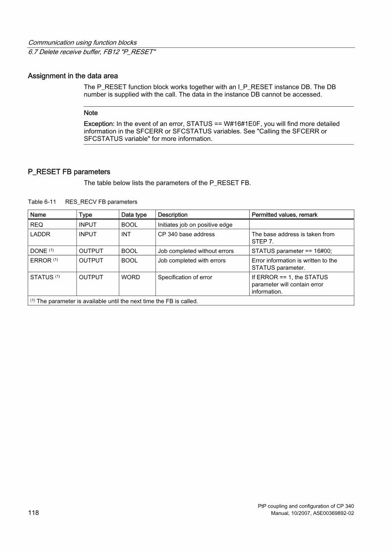
Communication using function blocks 6.7 Delete receive buffer, FB12 "P_RESET"
PtP coupling and configuration of CP 340 118 Manual, 10/2007, A5E00369892-02
Assignment in the data area The P_RESET function block works together with an I_P_RESET instance DB. The DB number is supplied with the call. The data in the instance DB cannot be accessed.
Note Exception: In the event of an error, STATUS == W#16#1E0F, you will find more detailed information in the SFCERR or SFCSTATUS variables. See "Calling the SFCERR or SFCSTATUS variable" for more information.
P_RESET FB parameters The table below lists the parameters of the P_RESET FB.
Table 6-11 RES_RECV FB parameters
Name Type Data type Description Permitted values, remark REQ INPUT BOOL Initiates job on positive edge LADDR INPUT INT CP 340 base address The base address is taken from
STEP 7. DONE (1) OUTPUT BOOL Job completed without errors STATUS parameter == 16#00; ERROR (1) OUTPUT BOOL Job completed with errors Error information is written to the
STATUS parameter. STATUS (1) OUTPUT WORD Specification of error If ERROR == 1, the STATUS
parameter will contain error information.
(1) The parameter is available until the next time the FB is called.

Communication using function blocks 6.7 Delete receive buffer, FB12 "P_RESET"
PtP coupling and configuration of CP 340 Manual, 10/2007, A5E00369892-02 119
Time sequence chart for the P_RESET FB The figure below illustrates the behavior of the DONE and ERROR parameters depending on the input circuit of REQ.
Figure 6-5 Time sequence chart for the P_RESET FB
Note The REQ input is edge-triggered. A positive edge at the REQ input is sufficient. The result of the logic operation must not be at "1" at any point during transfer.

Communication using function blocks 6.8 Parameterizing the Function Blocks
PtP coupling and configuration of CP 340 120 Manual, 10/2007, A5E00369892-02
6.8 Parameterizing the Function Blocks
Introduction This section is aimed at users who are upgrading from SIMATIC S5 to SIMATIC S7. The following subsections describe what you need to observe when programming function blocks in STEP 7.
6.8.1 General Information on Data Block Assignment
Addressing The data operands in data blocks are addressed bytewise in STEP 7 (in contrast to STEP 5, where addressing is word-based). You therefore have to convert the addresses of the data operands.
Figure 6-6 Contrasting Data Addressing in STEP 5 and STEP 7
The address of a data word in STEP 7 is doubled compared to STEP 5. It is no longer divided into a right and a left data byte. Bit numbering is always from 0 to 7.

Communication using function blocks 6.8 Parameterizing the Function Blocks
PtP coupling and configuration of CP 340 Manual, 10/2007, A5E00369892-02 121
Examples The STEP 5 data operands in the left column of the table become the STEP 7 data operands in the right column.
STEP 5 STEP 7 DW 10 DBW 20 DL 10 DBB 20 DR 10 DBB 21 D 10.0 DBX 21.0 D 10.8 DBX 20.0 D 255.7 DBX 511.7
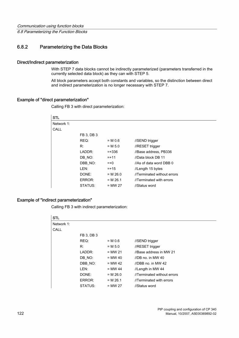
Communication using function blocks 6.8 Parameterizing the Function Blocks
PtP coupling and configuration of CP 340 122 Manual, 10/2007, A5E00369892-02
6.8.2 Parameterizing the Data Blocks
Direct/Indirect parameterization With STEP 7 data blocks cannot be indirectly parameterized (parameters transferred in the currently selected data block) as they can with STEP 5. All block parameters accept both constants and variables, so the distinction between direct and indirect parameterization is no longer necessary with STEP 7.
Example of "direct parameterization" Calling FB 3 with direct parameterization:
STL Network 1: CALL FB 3, DB 3 REQ: = M 0.6 //SEND trigger R: = M 5.0 //RESET trigger LADDR: =+336 //Base address, PB336 DB_NO: =+11 //Data block DB 11 DBB_NO: =+0 //As of data word DBB 0 LEN: =+15 //Length 15 bytes DONE: = M 26.0 //Terminated without errors ERROR: = M 26.1 //Terminated with errors STATUS: = MW 27 //Status word
Example of "indirect parameterization" Calling FB 3 with indirect parameterization:
STL Network 1: CALL FB 3, DB 3 REQ: = M 0.6 //SEND trigger R: = M 5.0 //RESET trigger LADDR: = MW 21 //Base address in MW 21 DB_NO: = MW 40 //DB no. in MW 40 DBB_NO: = MW 42 //DBB no. in MW 42 LEN: = MW 44 //Length in MW 44 DONE: = M 26.0 //Terminated without errors ERROR: = M 26.1 //Terminated with errors STATUS: = MW 27 //Status word

Communication using function blocks 6.8 Parameterizing the Function Blocks
PtP coupling and configuration of CP 340 Manual, 10/2007, A5E00369892-02 123
Parameterization of data words The specification of data words (partially-qualified specification) is not allowed because (depending on the actual addresses) the currently selected data block can no longer be determined in the standard function. If a data address is specified as an actual parameter, the fully-qualified specification must always be used. A fully-qualified specification can be either absolute or symbolic. Mixed addressing with fully-qualified data addresses is rejected by the compiler.
Example 1 The symbol name for the data block is entered in the symbol table, while the symbol name for the data address is declared in the corresponding data block.
STL DB 10.DBW 0 Absolute fully-qualified addressing CP_DB.SEND_DWNO Symbolic fully-qualified addressing
Example 2 The symbol name of the data block used, DB 10, is "CP_DB"; the symbol name for the send DB number is "SEND_DBNO" and is located in data block DB 10 in the data word DBW 0. The start address of the send frame is "SEND_DWNO" and is located in data block DB 10 in DBW 2; the frame length is "SEND_LEN" and is located in data block DB 10 in DBW 4. The variable used for the module address is the memory word "BGADR" (MW 21), for the DONE parameter the bit memory "SEND_DONE" (M 26.0), for the ERROR parameter the bit memory "SEND_ERROR" (M 26.1), and for the STATUS parameter the memory word "SEND_STATUS" (MW 27). The STL listings for the example are shown on the following page.

Communication using function blocks 6.8 Parameterizing the Function Blocks
PtP coupling and configuration of CP 340 124 Manual, 10/2007, A5E00369892-02
Example of an absolutely addressed actual address Calling FB 3 with absolutely addressed actual addresses:
STL Network 1: CALL FB 3, DB 3 REQ: = M 0.6 //SEND trigger R: = M 5.0 //RESET trigger LADDR: = MW 21 //Base address in MW 21 DB_NO: = DB 10.DBW
0 //DB no. in DBW 0 of DB 10
DBB_NO: = DB 10.DBW 2
//As of DBB no., located in DBW 2 of DB 10
LEN: = DB 10.DBW 4
//Length located in DBW 4 of DB 10
DONE: = M 26.0 //Terminated without errors ERROR: = M 26.1 //Terminated with errors STATUS: = MW 27 //Status word
Example of a symbolically addressed actual address Calling FB 3 with symbolically addressed actual addresses:
STL Network 1: CALL FB 3, DB 3 REQ: = M 0.6 //SEND trigger R: = M 5.0 //RESET trigger LADDR: = BGADR //Base address DB_NO: = CP_DB.SEND_DBNO //Send DB no. DBB_NO: = CP_DB.SEND_DWNO //Frame as of data byte LEN: = CP_DB.SEND_LEN //Frame length DONE: = SEND_DONE //Terminated without errors ERROR: = SEND_ERROR //Terminated with errors STATUS: = SEND_STATUS //Status word

Communication using function blocks 6.8 Parameterizing the Function Blocks
PtP coupling and configuration of CP 340 Manual, 10/2007, A5E00369892-02 125
EN/ENO mechanism The parameters EN and ENO are only present in the graphical representation (LAD or FBD). To process these parameters, the compiler uses the binary result (BR). The binary result is set to signal state "1" if the block was terminated without errors. If there was an error, the BR is set to "0".
Communication using function blocks 6.9 General Information on Program Processing
PtP coupling and configuration of CP 340 126 Manual, 10/2007, A5E00369892-02
6.9 General Information on Program Processing
Start-up Behavior of CP 340 Programmable Controller The parameterization data are generated using CP 340: Point-to-Point Communication, Parameter Assignment parameterization interface and transmitted to the CPU with the STEP 7 software. Each time the CPU is started up, the current parameters are transferred to the CP 340 by the system service of the CPU.
Start-up Behavior: FB-CP 340 Once the connection between the CPU and the CP 340 has been established, the CP 340 must be initialized. For each function block, P_SEND, P_RCV, P_PRINT, there is a separate start-up coordination. Before requests can be actively processed, the accompanying start-up procedure must be completed.
Disable interrupts The interrupts are not disabled in the function blocks.
Interrupt behavior The CP 340 module can trigger a diagnostics interrupt in the CPU. When this happens, the operating system provides the user with 4 bytes of interupt information. Interpretation of the interrupt information must be programmed by the user (OB 82). The CP 340 function blocks cannot be called in the process or diagnostics interrupt program.
Addressing the module The logical basic address is defined via STEP 7 and must be specified by the user under the block parameter LADDR.

PtP coupling and configuration of CP 340 Manual, 10/2007, A5E00369892-02 127
Startup 77.1 Operating Modes of the CP 340
Introduction The CP 340 has the operating modes STOP, new parameterization and RUN.
STOP When the CP 340 is in STOP mode, no protocol driver is active and all send and receive jobs from the CPU are given a negative acknowledgment. The CP 340 remains in STOP mode until the cause of the stop is removed (e.g., break, invalid parameter).
Assignment of new parameters For new parameterization, the protocol driver is initialized. The SF LED is on during new parameterization. Sending and receiving are not possible, and send and receive frames stored in the CP 340 are lost when the driver is subjected to a warm restart. Communication between the CP and the CPU is restarted (active frames are cancelled.) At the end of the new parameterization, the CP 340 is in RUN mode and is ready to send and receive.
RUN The CP 340 executes the CPU jobs. The frames received by the communication partner will be prepared for their transfer to the CPU.

Startup 7.2 Startup Characteristics of the CP 340
PtP coupling and configuration of CP 340 128 Manual, 10/2007, A5E00369892-02
7.2 Startup Characteristics of the CP 340
Introduction The CP 340 start-up is divided into two phases: ● Initialization (CP 340 in POWER ON mode) ● Parameterization
Initialization As soon as the CP 340 is connected to the power supply, the serial interface is supplied with default parameters (the interface parameters are given preset values at the factory) of the module. As soon as the initialization is complete, the CP 340 automatically starts up with the 3964R driver with block check by default. The CP 340 is now ready for operation.
Parameterization During parameterization the CP 340 receives the module parameters assigned to the current slot, which were generated using CP 340: Point-to-Point Communication, Parameter Assignment parameterization interface. Reparameterization is performed. The default parameters are overwritten by the newly set module parameters.

Startup 7.3 Behavior of the CP 340 on Operating Mode Transitions of the CPU
PtP coupling and configuration of CP 340 Manual, 10/2007, A5E00369892-02 129
7.3 Behavior of the CP 340 on Operating Mode Transitions of the CPU
Introduction Once the CP 340 has been started up, all data is exchanged between the CPU and the CP 340 by means of the function blocks.
CPU-STOP In CPU-STOP mode, communication via the S7 backplane bus is not possible. Any active CP-CPU data transmission, including both send and receive message frames, is aborted and the connection is reestablished. Data traffic at the RS 232C interface of the CP 340-RS 232C is continued with the ASCII driver and the printer driver in the case of parameterization without flow control. In other words, the current send request is completed. In the case of the ASCII driver, receive message frames continue to be received until the receive buffer is full.
CPU Startup At start-up, the CPU sends off the parameters generated with CP 340: Point-to-Point Communication, Parameter Assignment parameterization interface. The CP 340 only reparameterizes if the parameters have changed. Through appropriate parameterization with the parameterizing software, you can have the receive buffer on the CP 340 deleted automatically at CPU start-up.
CPU RUN When the CPU is in RUN mode, sending and receiving are unrestricted. In the first FB cycles following the CPU restart, the CP 340 and the corresponding FBs are synchronized. No new P_SEND, P_RCV or P_PRINT FB is executed until this is finished.
Points to Note when Sending Message Frames, Printer Output Transmission of message frames and printer output are possible only in CPU RUN mode. If the CPU switches to STOP mode during CPU > CP data transmission, the P_SEND or P_PRINT FB reports the error "current program interrupted, request aborted due to BREAK/restart/reset" after restart.
Note The CP 340 does not send data to the communications partner until it has received all data from the CPU.

Startup 7.3 Behavior of the CP 340 on Operating Mode Transitions of the CPU
PtP coupling and configuration of CP 340 130 Manual, 10/2007, A5E00369892-02
Points to Note when Receiving Message Frames With the CP 340: Point–to–Point Communication, Parameter Assignment tool can be used to configure the “Delete CP receive buffer at startup = yes/no.” ● If you select "yes", the receive buffer on the CP 340 is automatically deleted when the
CPU mode changes from STOP to RUN. ● If you select "no", as many message frames as you have parameterized are stored in the
CP 340 receive buffer (1 to 250). If the CPU changes to STOP mode during transmission CP < CPU, the P_RCV FB reports the error "current program interrupted, request aborted due to BREAK/restart/ reset" after restart. If "Delete CP receive buffer at startup = no" is set, the message frame is retransmitted from the CP 340 to the CPU.
See also Serial Transmission of a Character (Page 21)

PtP coupling and configuration of CP 340 Manual, 10/2007, A5E00369892-02 131
Diagnostics with the CP 340 8Introduction
The diagnostics functions of the CP 340 enable you to quickly localize any errors which occur. The following diagnostics options are available: ● Diagnosis via the Display Elements of the CP 340 ● Diagnosis via the STATUS output of the function blocks ● Diagnosis via the S7-300 backplane bus ● Diagnostics by means of the diagnostic buffer of the CP 340
Display elements (LED) The display elements show the operating mode or possible error states of the CP 340. The display elements give you an initial overview of any internal or external errors as well as interface-specific errors.
STATUS Output of the FBs The P_SEND, P_RCV and P_PRINT function blocks have a STATUS output for error diagnostics. Reading the STATUS output of the function blocks gives you information on errors which have occurred during communication. You can interpret the STATUS output in the user program. The CP 340 also enters the diagnostic events at the STATUS output in its diagnostic buffer.
S7-300 backplane bus The CP 340 can trigger a diagnostics alarm on the CPU assigned to it. CP 340 provides 4 bytes of diagnostics information at the S7-300 backplane bus. This information is analyzed via the user program (OB 82) or using a programming device to read from the CPU diagnostics buffer. The CP 340 also writes diagnostic events which have triggered a diagnostics interrupt to its diagnostic buffer. If a diagnostics alarm event occurs, the SF LED (red) lights up.
Diagnostic Buffer of the CP 340 All the CP 340's errors are entered in its diagnostic buffer. In the same way as with the diagnostic buffer of the CPU, you can also use the STEP 7 information functions on the programming device to display the information in the CP diagnostic buffer.
Diagnostics with the CP 340 8.1 Diagnosis via the Display Elements of the CP 340
PtP coupling and configuration of CP 340 132 Manual, 10/2007, A5E00369892-02
8.1 Diagnosis via the Display Elements of the CP 340
Introduction The display elements of the CP 340 provide information on the CP 340. The following display functions are distinguished: ● Group error displays
– SF (red) An error has occurred, or new parameters were assigned ● Special displays
– TXD (green)Sending active; lights up when the CP 340 is sending user data via the interface
– RXD (green)Receiving active; lights up when the CP 340 is receiving user data via the interface
Group error LED SF The group alarm LED SF always lights up after POWER ON and goes out after initialization. If parameterization data has been generated for the CP 340, the SF LED again lights up briefly during reparameterization. The group alarm LED SF lights up whenever the following occur: ● Hardware faults ● Firmware errors ● Parameterization errors ● BREAKs (receive cable between CP 340 and communications partner becomes
disconnected). The BREAK display on the Group alarm LED SF only occurs if the BREAK monitoring was not deactivated with the parameter assignment interface.
Note In the event of a BREAK on the RXD line, the group alarm LED SF and the special LED RXD light up.

Diagnostics with the CP 340 8.2 Diagnostics Messages of the Function Blocks P_SEND, P_RCV and P _PRINT
PtP coupling and configuration of CP 340 Manual, 10/2007, A5E00369892-02 133
8.2 Diagnostics Messages of the Function Blocks P_SEND, P_RCV and P_PRINT
Introduction Every function block has a STATUS parameter for error diagnostics. The STATUS message numbers always have the same meaning, irrespective of which function block is used.
Numbering scheme for event class/event number The figure below illustrates the structure of the STATUS parameter.
Figure 8-1 Structure of the STATUS parameter
Example The figure below illustrates the content of the STATUS parameter for the "Job aborted due to warm restart, hot restart or reset" event (event class: 1EH, event number 0DH).
Figure 8-2 Example: Structure of the STATUS parameter for the the "Job aborted due to warm
restart, hot restart or reset" event

Diagnostics with the CP 340 8.2 Diagnostics Messages of the Function Blocks P_SEND, P_RCV and P _PRINT
PtP coupling and configuration of CP 340 134 Manual, 10/2007, A5E00369892-02
Event classes The table below describes the various event classes and numbers.
Table 8-1 Event classes and event numbers
Event class 5 (05H): "Error while processing CPU request"
Event no. Event To correct or avoid errors (05)02H Job not permitted in this CP operating mode (e.g.,
device interface not parameterized) Evaluate the diagnostic interrupt and rectify the error accordingly.
(05)05H Only for printer drivers: System data block with message texts not available on the CP
Use the parameter assignment software to configure the message texts, and then carry out a warm restart.
(05)06H Only for printer drivers: Message text not available
Use the parameter assignment software to configure the message texts, and then carry out a warm restart.
(05)07H Only for printer drivers: Message text too long
Edit the message text to reduce it to a length of fewer than 150 characters (or no more than 250 characters if it contains variables).
(05)08H Only for printer drivers: Too many conversion statements
You have configured more conversion statements than variables. Conversion statements without associated variables will be ignored.
(05)09H Only for printer drivers: Too many variables
You have configured more variables than conversion statements. Variables without associated conversion statements will not be output.
(05)0AH Only for printer drivers: Unknown conversion statement
Check the conversion statement. Undefined or unsupported conversion statements are replaced in the printout with ******.
(05)0BH Only for printer drivers: Unknown control statement
Check the control statement. Undefined or unsupported control statements will be ignored. The control statement will not be output as text either.
(05)0CH Only for printer drivers: Conversion statement not executable
Check the conversion statement. Conversion statements that cannot be executed are output in the printout in accordance with the defined width and the valid remainder of the conversion statement or the default display with * characters.
(05)0DH Only for printer drivers: Width in conversion statement too small or too great
Correct the specified width of the variable in the conversion statement on the basis of the variable's maximum possible number of characters in text-based display types (A, C, D, S, T, Y, Z). Only as many characters as will fit in the specified width appear in the printout; the text is truncated to this width. In all other cases, * characters are output corresponding to the width.
(05)0EH Only for 3964(R) and ASCII drivers: Invalid frame length
Frame length is > 1,024 bytes. The rest of the frame (> 1,024 bytes) is still being received by the CP 340; this means that the first part of the frame is discarded. Select a shorter frame length.

Diagnostics with the CP 340 8.2 Diagnostics Messages of the Function Blocks P_SEND, P_RCV and P _PRINT
PtP coupling and configuration of CP 340 Manual, 10/2007, A5E00369892-02 135
Event class 5 (05H): "Error while processing CPU request"
Event no. Event To correct or avoid errors (05)1BH Only for printer drivers:
Precision invalid Correct the specified precision in the conversion statement. The precision is always initialized with a dot prefix to identify and limit the width (for example, ".2" to output the decimal point and two decimals.) Precision is only relevant to display types A, D, F, and R. It is ignored otherwise.
(05)1CH Only for printer drivers: Variable invalid (variable length incorrect/incorrect type)
Correct the specified variable. The corresponding table indicates the possible data types for each display type.
(05)1EH Only for printer drivers: The "line end sequences" sent with this job (i.e.: $R / $L / $N) do not fit (any longer) on the (initial) page.
Increase the length of your page, reduce the number of lines (or line feeds) or spread your printout over a number of pages.
Event class 7 (07H): "Send error"
Event no. Event To correct or avoid errors (07)01H Only for 3964(R):
Sending of the first repetition: - An error was detected when transmitting the frame, or - The partner requested a repetition by means of a negative acknowledgment code (NAK).
A repetition is not an error, but it can indicate that there is interference on the data link or the partner device has malfunctioned. If the frame still has not been transmitted after the maximum number of repetitions, an error number is output that describes the first error that occurred.
(07)02H Only for 3964(R): Error establishing connection: After STX was sent, NAK or any other code (except for DLE or STX) was received.
Check for malfunction of the partner device; you may need to use an interface test device (FOXPG) interconnected in the data link.
(07)03H Only for 3964(R): Acknowledgment delay time (QVZ) exceeded: After STX was sent, partner did not respond within the acknowledgment delay time.
The partner device is too slow or not ready to receive, or there is a break in the transmission line, for example. Check for malfunction of the partner device; you may need to use an interface test device (FOXPG) interconnected in the data link.
(07)04H Only for 3964(R): Termination by partner: One or more codes were received from the partner during sending.
Check whether the partner is also indicating errors, possibly because not all transmitted data arrived (e.g., break in the transmission line), fatal errors are pending or the partner device has malfunctioned. You may need to use an interface test device (FOXPG) interconnected in the data link to check this.
(07)05H Only for 3964(R): Negative acknowledgment when sending
Check whether the partner is also indicating errors, possibly because not all transmitted data arrived (e.g., break in the transmission line), fatal errors are pending or the partner device has malfunctioned. You may need to use an interface test device (FOXPG) interconnected in the data link to check this.

Diagnostics with the CP 340 8.2 Diagnostics Messages of the Function Blocks P_SEND, P_RCV and P _PRINT
PtP coupling and configuration of CP 340 136 Manual, 10/2007, A5E00369892-02
Event class 7 (07H): "Send error"
Event no. Event To correct or avoid errors (07)06H Only for 3964(R):
End-of-connection error: - Partner rejected frame at end of connection with NAK or a random string (except for DLE), or - Acknowledgment code (DLE) received too early.
Check whether the partner is also indicating errors, possibly because not all transmitted data arrived (e.g., break in the transmission line), fatal errors are pending or the partner device has malfunctioned. You may need to use an interface test device (FOXPG) interconnected in the data link to check this.
(07)07H Only for 3964(R): Acknowledgment delay time exceeded at end of connection or response monitoring time exceeded after a send frame: After connection termination with DLE ETX, no response received from partner within acknowledgment delay time.
Partner device too slow or faulty. You may need to use an interface test device (FOXPG) interconnected in the data link to check this.
(07)08H Only for ASCII drivers and printer drivers: The wait time for XON or CTS = ON has expired.
The communication partner is faulty, too slow or has been taken offline. Check the communication partner; you may need to change the parameter assignment.
(07)0BH Only for 3964(R): Initialization conflict cannot be resolved because both partners have high priority.
Change the parameter assignment.
(07)0CH Only for 3964(R): Initialization conflict cannot be resolved because both partners have low priority.
Change the parameter assignment.
Event class 8 (08H): "Receive error"
Event no. Event To correct or avoid errors (08)01H Only for 3964(R):
Expectation of the first repetition: An error was detected on receiving a frame and the CP requested repetition from the partner via a negative acknowledgment (NAK).
A repetition is not an error, but it can indicate that there is interference on the data link or the partner device has malfunctioned. If the frame still has not been transmitted after the maximum number of repetitions, an error number is output that describes the first error that occurred.
(08)02H Only for 3964(R): Error establishing connection: - In idle mode, one or more random codes (other than NAK or STX) were received, or - After an STX was received, partner sent more codes without waiting for response DLE. After partner power ON: - While partner is being activated, CP receives an undefined code.
Check for malfunction of the partner device; you may need to use an interface test device (FOXPG) interconnected in the data link.

Diagnostics with the CP 340 8.2 Diagnostics Messages of the Function Blocks P_SEND, P_RCV and P _PRINT
PtP coupling and configuration of CP 340 Manual, 10/2007, A5E00369892-02 137
Event class 8 (08H): "Receive error"
Event no. Event To correct or avoid errors (08)05H Only for 3964(R):
Logical error while receiving: After DLE was received, a further random code (other than DLE or ETX) was received.
Check whether the partner always duplicates the DLE in the frame header and data string or the connection is terminated with DLE ETX. Check for malfunction of the partner device; you may need to use an interface test device (FOXPG) interconnected in the data link.
(08)06H Character delay time (ZVZ) exceeded: - Two successive characters were not received within the character delay time, or Only for 3964(R): - 1. character after sending of DLE while establishing connection was not received within the character delay time.
Partner device too slow or faulty. Check this using an interface test device (FOXPG) interconnected in the data link.
(08)07H Illegal frame length: A zero-length frame has been received.
Receipt of a zero-length frame is not an error. Check why the communication partner is sending frames without user data.
(08)08H Only for 3964(R): Error in block check character (BCC): The value of BCC calculated internally does not match the BCC received by the partner when the connection was terminated.
Check whether the connection is seriously disrupted; in this case you may also occasionally see error codes. Check for malfunction of the partner device; you may need to use an interface test device (FOXPG) interconnected in the data link.
(08)09H Only for 3964(R): The number of repetitions must the set to the same value.
Assign parameters to the same block wait time at communications partner as at CP 340. Check for malfunction of the communication partner; you may need to use an interface test device (FOXPG) interconnected in the data link.
(08)0AH There is no free receive buffer available: No receive buffer space available for receiving data.
The P_RCV FB must be called more frequently.
(08)0CH Transmission error: - A transmission error (parity/stop bit/overflow error) has been detected. Only for 3964(R): - If this happens during send or receive operations, repetition is started. - If a corrupted character is received in idle mode, the error is reported immediately so that disturbances on the data link can be detected early. - If the SF LED (red) and the RxD LED (green) light up, there is a break in the connecting cable (cable break) between the two communication partners.
Disturbances on the data link cause frame repetitions, thus lowering user data throughput. The risk of undetected error increases. Change your system setup or cable wiring. Check the connecting cables of the communication partners or check whether both devices have the same setting for baud rate, parity and number of stop bits.
(08)0DH BREAK: Break in receive line to partner.
Reconnect or switch on partner.

Diagnostics with the CP 340 8.2 Diagnostics Messages of the Function Blocks P_SEND, P_RCV and P _PRINT
PtP coupling and configuration of CP 340 138 Manual, 10/2007, A5E00369892-02
Event class 8 (08H): "Receive error"
Event no. Event To correct or avoid errors (08)10H Only for ASCII drivers:
Parity error: If the SF LED (red) and the RxD LED (green) light up, there is a break in the connecting cable (cable break) between the two communication partners.
Check the connecting cables of the communication partners or check whether both devices have the same setting for baud rate, parity and number of stop bits. Change your system setup or cable wiring.
(08)11H Only for ASCII drivers: Character frame error: If the SF LED (red) and the RxD LED (green) light up, there is a break in the connecting cable (cable break) between the two communication partners.
Check the connecting cables of the communication partners or check whether both devices have the same setting for baud rate, parity and number of stop bits. Change your system setup or cable wiring.
(08)12H Only for ASCII drivers: More characters were received after the CP had sent XOFF or set CTS to OFF.
Reset the parameters for the communication partner or read data from CP more quickly.
(08)18H Only for ASCII drivers: DSR = OFF or CTS = OFF
The partner has switched the DSR or CTS signal to "OFF" before or during a transmission. Check the partner's control of the RS 232C accompanying signals.
Displaying and evaluating the STATUS output You can display and evaluate the actual address of the function blocks' STATUS outputs.
Note An error message is only output if the ERROR bit (job completed with error) is set at the same time. In all other cases the STATUS word is zero.

Diagnostics with the CP 340 8.2 Diagnostics Messages of the Function Blocks P_SEND, P_RCV and P _PRINT
PtP coupling and configuration of CP 340 Manual, 10/2007, A5E00369892-02 139
Event class 30 Event class 30 contains error messages, which could be output during communication via the S7 backplane bus between CP 340 and the CPU. The table below contains a description of event class 30.
Table 8-2 Event class 30
Event class 30 (1EH): "Communication error between CP and CPU"
Event no. Event More information/To correct and avoid errors (1E)0DH Job aborted due to warm restart, hot restart or reset (1E)0EH Static error when calling RD_REC SFC or RDREC
SFB. The RET_VAL return value for the SFC/SFB is made available to you for evaluation in the SFCERR or SFCSTATUS variable respectively on the instance DB.
Load the SFCERR or SFCSTATUS variable from the instance DB.
(1E)0FH Static error when calling WR_REC SFC or RDREC SFB. The RET_VAL return value for the SFC/SFB is made available to you for evaluation in the SFCERR or SFCSTATUS variable respectively on the instance DB.
Load the SFCERR or SFCSTATUS variable from the instance DB.
(1E)41H The number of bytes specified at the FBs' LEN parameter is not permissible.
You must stay within a range of values of 1 to 1,024 bytes.
(1E)41H P_PRINT FB: The number of bytes specified for the variable or format string in the pointer DB under length is not permissible.
You must specify a permissible length: 32 bytes for variables, 150 bytes for format strings.
(1E)43H P_PRINT FB: No pointer available for format string.
Enter the data block no. and data word no. for the format string in the pointer DB.
Calling the SFCERR or SFCSTATUS variable You can call the SFCERR or SFCSTATUS variable to obtain more detailed information about the pending event class 30 error, 14 (1E0EH) or 15 (1E0FH). You can only load the SFCERR or SFCSTATUS variable by means of symbolic access to the corresponding function block's instance DB. The error messages written to the SFCERR variable are listed in the reference manual titled System Software for S7 300/400, System and Standard Functions under the SFC 58 "WR_REC" and SFC 59 "RD_REC" system functions, refer to the error information or the chapter titled "Evaluating errors with the RET_VAL output parameter". The error messages written to the SFCSTATUS variable are listed in the reference manual titled System Software for S7 300/400, System and Standard Functions under the SFB 52 "RDREC" and SFB 53 "WRREC" system functions, refer to the error information.

Diagnostics with the CP 340 8.3 Diagnostics via the S7-300 backplane bus
PtP coupling and configuration of CP 340 140 Manual, 10/2007, A5E00369892-02
8.3 Diagnostics via the S7-300 backplane bus
Introduction The CP 340 can trigger a diagnostics alarm on the assigned CPU, thus indicating a malfunction of the CP 340. You can specify at parameterization whether the CP 340 is to trigger a diagnostics interrupt or not in the event of serious errors. "Generate interrupt = no is set by default.
Diagnostics interrupt In the event of a fault the CP 340 provides diagnostics information on the S7-300 backplane bus. In response to a diagnostics interrupt, the CPU reads the system-specific diagnostics data and enters it in its diagnostics buffer. You can read the contents of the diagnostics buffer on the CPU using a programming device. If a diagnostics alarm event occurs, the SF LED (red) lights up. In addition, the OB 82 is called with this diagnostics data as start information.
Organization block OB 82 You have the option of programming error responses in the user program in the OB 82. If no OB 82 is programmed, the CPU automatically enters STOP mode in the event of a diagnostics alarm.
Diagnostics Information (as Bit Pattern) Diagnostics information The CP 340 provides 4 bytes of diagnostics information. To display the error that has occurred, these bytes are occupied as follows: 2. Byte: The 2nd byte of diagnostics data contains the class ID of the CP 340 in bits 0 to 3.
2. bytes 7 6 5 4 3 2 1 0 0 0 0 0 1 1 0 0
1., 3. and 4th byte: The 1st, 3rd and 4th byte of the diagnostics data represent the error which has occurred.

Diagnostics with the CP 340 8.3 Diagnostics via the S7-300 backplane bus
PtP coupling and configuration of CP 340 Manual, 10/2007, A5E00369892-02 141
Bit 0 in the 1st byte is the group error display (SF). Bit 0 is always set to "1" if at least one bit from bits 1 to 7 is set to "1", i.e. if at least one error is entered in the diagnostics data.
Event 1. bytes 3. bytes 4. bytes 7 6 5 4 3 2 1 0 7 6 5 4 3 2 1 0 7 6 5 4 3 2 1 0 Wire break 0 0 1 0 0 1 0 1 0 0 0 0 0 0 1 0 0 0 0 0 0 0 0 0 Incorrect parameter 1 0 0 0 0 0 0 1 0 0 0 0 0 0 0 0 0 0 0 0 0 0 0 0 No parameter 0 1 0 0 0 0 0 1 0 0 0 0 0 0 0 0 0 0 0 0 0 0 0 0 RAM error 0 0 0 0 0 0 1 1 0 0 0 0 0 0 0 0 0 0 0 0 1 0 0 0 ROM error 0 0 0 0 0 0 1 1 0 0 0 0 0 0 0 0 0 0 0 0 0 1 0 0 System error 0 0 0 0 0 0 1 1 0 0 0 0 0 0 0 0 0 0 0 0 0 0 0 0
Diagnosis Information (in KH Format) The following table shows the 4 bytes diagnosis information of the CP 340 in the KH format.
Event 1. bytes 2. bytes 3. bytes 4. bytes Wire break 25H 0CH 02H 00H Incorrect parameter
81H 0CH 00H 00H
No parameter 41H 0CH 00H 00H RAM error 03H 0CH 00H 08H ROM error 03H 0CH 00H 04H System error 03H 0CH 00H 00H
Dependency of Diagnostics Alarm on CPU Operating Mode A diagnostics alarm is generated via the I/O bus when fault events (rising edge) and back-to-normal events (falling edge) occur. When the CPU switches from STOP mode to RUN mode, the following happens: ● All events entered in the diagnostics buffer of the CPU are deleted, ● Events (both fault and back-to-normal) which occurred when the CPU was in STOP mode
are not stored, ● Events that are still present when the CPU is back to RUN mode are signaled via the
diagnostics alarm.
See also Basic parameters of the CP 340 (Page 53)

Diagnostics with the CP 340 8.4 Diagnostics by means of the diagnostic buffer of the CP 340
PtP coupling and configuration of CP 340 142 Manual, 10/2007, A5E00369892-02
8.4 Diagnostics by means of the diagnostic buffer of the CP 340
Diagnostic buffer on the CP 340 The CP 340 has its own diagnostic buffer, in which all the diagnostic events of the CP 340 are entered in the sequence in which they occur. The following are displayed in the diagnostic buffer of the CP 340: ● The operating mode of the CP 340 ● Hardware/firmware errors on the CP 340 ● Initialization and parameterization errors ● Errors during execution of a CPU job ● Data transmission errors (send and receive errors) The diagnostic buffer allows the causes of errors in point-to-point communication to be evaluated subsequently in order, for example, to determine the causes of a STOP of the CP 340 or to trace the occurrence of individual diagnostic events.
Note The diagnostic buffer is a ring buffer for a maximum of 9 diagnostic entries. When the diagnostic buffer is full, the oldest entry is deleted when a new entry is made in it. The most recent entry always comes first. When the power of the CP 340 is switched off, the content of the diagnostic buffer is lost.
Reading the diagnostic buffer at the programming device The content of the diagnostic buffer of the CP 340 can be read by means of the STEP 7 information functions.
Note Diagnostic events in the diagnostic buffer of the CP 340 can be read using STEP 7 as of Version 3.1.
All the user-relevant information in the CP diagnostic buffer is displayed to you on the "Diagnostic Buffer" tab in the "Module Information" dialog box. You can open SIMATIC Manager in STEP 7 to call the "Module Information" dialog box. Prerequisite: In order to obtain module information, there must be an online connection from the programming device to the programmable controller (online view in the project window).

Diagnostics with the CP 340 8.4 Diagnostics by means of the diagnostic buffer of the CP 340
PtP coupling and configuration of CP 340 Manual, 10/2007, A5E00369892-02 143
Proceed as follows: 1. Open the SIMATIC 300 station concerned (double-click or select menu command Edit >
Open). 2. Then open the "Hardware" object (also by double-clicking or selecting menu command
Edit > Open). Result: The window containing the configuration table appears.
3. Select the CP 340 in the configuration table. 4. Select the menu command PLC > Module Information.
Result: The "Module Information" dialog box for the CP 340 appears. The first time the dialog is called, the "General" tab appears (default setting).
5. Go to the "Diagnostic Buffer" tab. Result: The latest diagnostic results for the CP 340 are displayed on the "Diagnostic Buffer" tab in plain text. Additional information about error causes may appear in the "Additional information" output field. Click "Update" to read the latest data from the CP 340. Click "Help on Event" to show a help text for the selected diagnostic event containing information about troubleshooting.

Diagnostics with the CP 340 8.4 Diagnostics by means of the diagnostic buffer of the CP 340
PtP coupling and configuration of CP 340 144 Manual, 10/2007, A5E00369892-02

PtP coupling and configuration of CP 340 Manual, 10/2007, A5E00369892-02 145
Programming Example for Standard Function Blocks 9Introduction
The programming example given here describes standard functions for operating the CP 340 communications processor.
Objective The programming example ● aims to show examples of the most important functions ● enables the correct functioning of the connected hardware to be checked (and is
therefore simple and easy to follow) ● can easily be extended for your own purposes. The example shows how a connection to a communications partner can be configured using the standard function blocks P_SEND and P_RCV (to send and receive data respectively). The example also shows how data can be output to a printer using the P_PRINT function block and how the inputs and outputs of the CP 340 can be controlled and monitored using the V24_STAT and V24_SET standard functions. There are two SIMATIC stations in the example because the CP 340 has to be parameterized differently for sending/receiving data and for printer output: ● 1. 2nd station: Computer link with the P_SEND and P_RCV function blocks ● 2. 2nd station: Printing and reading and controlling RS 232C secondary signals with the
P_PRINT function block and the V24_STAT and V24_SET functions The CP 340 is parameterized by the CPU when the latter is started up (system service).
Prerequisite The example can be executed with the minimum hardware equipment (2 bytes for inputs, 2 bytes for outputs). The STEP 7 function Monitor/Modify Variables is also used (e.g. to modify transmitted data).
The program example The program example of the CP 340 is supplied on a CD which comes with this manual. The CD also contains the parameterization interface and the function blocks. It is available both compiled and as an ASCII source file. A list of all the symbols used in the example is also included.

Programming Example for Standard Function Blocks 9.1 Device Configuration
PtP coupling and configuration of CP 340 146 Manual, 10/2007, A5E00369892-02
9.1 Device Configuration
Application To try out the sample program, you could use the following devices: ● One S7-300 programmable controller (mounting rack, power supply, CPU) ● One CP 340 module with a communications partner (e.g. a second CP) or printer, or you
could plug in a "short-circuit connector", i.e. the send line is bridged to the receive line ● One simulator module with inputs and outputs (or alternatively one digital input module
and one digital output module) ● One programming device (e.g. PG 740).
Note You do not need the digital inputs and outputs if all functions are executed with the STEP 7 function Monitor/Modify Variables. In this case, you must change the program in organization block OB 1.
9.2 Settings
Settings in the CPU via STEP 7 You must configure your controller setup with STEP 7: ● Slot 1: Power supply ● Slot 2: CPU ● Slot 4: Digital input, IB0 and IB1 ● Slot 5: Digital output, QB4 and QB5 ● Slot 6: CP 340, start address P288
Settings on the CP 340 You cannot make any hardware settings on the CP 340. All relevant data are configured via STEP 7, including the parameters for the CP 340, using the CP 340: Point–to–Point Communication, Assigning Parameters, and then download those data to the CPU.

Programming Example for Standard Function Blocks 9.2 Settings
PtP coupling and configuration of CP 340 Manual, 10/2007, A5E00369892-02 147
You can run the program example for the computer link without making changes in the application program with:
● 3964(R) procedure ● ASCII driver with "on expiry of character delay time" end criterion ● ASCII driver with "on receipt of fixed message frame length" end criterion. For the ASCII driver with the "on receipt of the end character(s)" end criterion, you must also program the end codes. The program example for the printer can be run with the printer driver only. The "read and control RS 232C secondary signs" functions can only be carried out with the ASCII driver. Prerequisite is that you have not set the “Automat. operation of V24 signals" on the "Transfer" tab.

Programming Example for Standard Function Blocks 9.3 Blocks Used
PtP coupling and configuration of CP 340 148 Manual, 10/2007, A5E00369892-02
9.3 Blocks Used
Blocks Used The table below shows the blocks used for the sample program.
Block Symbol Description OB 1 CYCLE Cyclic program processing OB 100 RESTART Restart processing DB 2 DB_P_RCV Instance DB for P_RCV FB DB 3 DB_P_SEND Instance DB for P_SEND FB DB 4 DB_P_PRINT Instance DB for P_PRINT FB DB 10 SEND_DB Send data block DB 20 RCV_DB Receive data block DB 30 DB_PRT_AUFTR Pointer DB for format string and variables DB 31 DB_VAR1 DB data for variable 1 DB 32 DB_VAR2 DB data for variable 2 DB 33 DB_VAR3 DB data for variable 3 DB 34 DB_VAR4 DB data for variable 4 DB 35 DB_STRING DB data for format string FB 2 P_RCV Standard FB for receiving data FB 3 P_SEND Standard FB for sending data FB 4 P_PRINT Standard FB for outputting message FC 5 V24_STAT Standard FC for reading CP outputs FC 6 V24_SET Standard FC for writing CP outputs FC 8 DT_TOD Standard FC for converting the DT format to TOD FC 9 CPU_TIME Standard FC for reading CPU time and converting to TOD FC 10 ORG_CYC Organization of cycle FC 11 SEND_CYC Sending Data FC 12 RCV_CYC receiving data FC 13 PRN_ZYK Output message FC 14 V24_CYC Controlling RS 232C secondary signals

Programming Example for Standard Function Blocks 9.4 Example “Point–to–Point Communication”
PtP coupling and configuration of CP 340 Manual, 10/2007, A5E00369892-02 149
9.4 Example “Point–to–Point Communication”
Introduction The inputs and outputs are mapped to memory bits at the beginning and end of OB 1. Only the memory bits are used in the test program.
Inputs and outputs used for FB 2 and FB 3 The table below shows the assignment of the inputs/outputs and memory bits.
Symbol Input/Output Bit memory Comment ANW_RECH I 0.0 M 0.0 "1" = Select "point–to–point communication" ANW_DRUCK I 0.1 M 0.1 "0" signal RESET_SP I 0.2 M 0.2 Start RESET SEND RESET_R I 0.3 M 0.3 Start RESET RCV I 0.4 M 0.4 Free I 0.5 M 0.5 Free REQ_SP I 0.6 M 0.6 Start SEND job EN_R_R I 0.7 M 0.7 Enable receive AUFTR_1_SP I 1.0 M 1.0 Send job selection; "1" = job 1 AUFTR_2_SP I 1.1 M 1.1 Send job selection; "1" = job 2 AUFTR_1_R I 1.2 M 1.2 Enable receipt of job selection; "1" = job 1 AUFTR_2_R I 1.3 M 1.3 Enable receipt of job selection; "1" = job 2 I 1.4 M 1.4 Free I 1.5 M 1.5 Free I 1.6 M 1.6 Free I 1.7 M 1.7 Free Display FB parameter A_DONE_SP Q 4.0 M 8.0 SEND DONE A_ERROR_SP Q 4.1 M 8.1 SEND ERROR A_BIE_SP Q 4.2 M 8.2 SEND binary result Q 4.3 M 8.3 “0” A_NDR_R Q 4.4 M 8.4 RCV NDR A_ERROR_R Q 4.5 M 8.5 RCV ERROR A_BIE_R Q 4.6 M 8.6 RCV binary result Q 4.7 M 8.7 “0” Q 5.0 M 9.0 “0” Q 5.1 M 9.1 “0” Q 5.2 M 9.2 “0” Q 5.3 M 9.3 “0” Q 5.4 M 9.4 “0” Q 5.5 M 9.5 “0” Q 5.6 M 9.6 “0” Q 5.7 M 9.7 “0”

Programming Example for Standard Function Blocks 9.4 Example “Point–to–Point Communication”
PtP coupling and configuration of CP 340 150 Manual, 10/2007, A5E00369892-02
Input/Output parameters for FB 2 and FB 3 The table below shows how the input/output parameters of FB 2 and FB 3 are mapped to bit memories.
Symbol Address Data format Comment SEND_DONE M 26.0 BOOL SEND: DONE parameter SEND_ERROR M 26.1 BOOL SEND: ERROR parameter SEND_BIE M 26.2 BOOL SEND: Binary result RCV_NDR M 29.0 BOOL RCV: NDR parameter RCV_ERROR M 29.1 BOOL RCV: ERROR parameter RCV_BIE M 29.2 BOOL RCV: Binary result BGADR MW 21 INT Logical base address SEND_STATUS MW 27 WORD SEND: STATUS parameter RCV_STATUS MW 30 WORD RCV: STATUS parameter SEND_DBNO MW 40 INT SEND: DB_NO parameter SEND_DWNO MW 42 INT SEND: DBB_NO parameter SEND_LEN MW 44 INT SEND: LEN parameter RCV_DBNO MW 50 INT RCV: DB_NO parameter RCV_DWNO MW 52 INT RCV: DBB_NO parameter RCV_LEN MW 54 INT RCV: LEN parameter
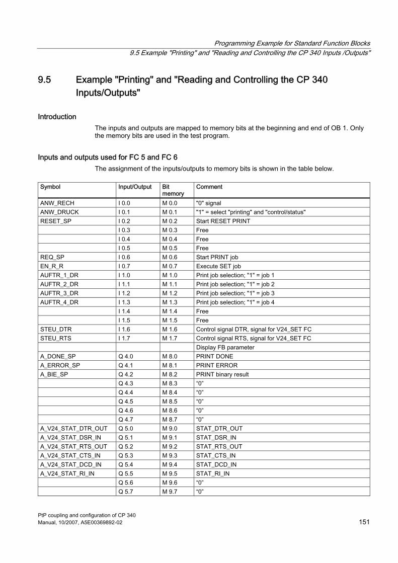
Programming Example for Standard Function Blocks 9.5 Example "Printing" and "Reading and Controlling the CP 340 Inputs /Outputs"
PtP coupling and configuration of CP 340 Manual, 10/2007, A5E00369892-02 151
9.5 Example "Printing" and "Reading and Controlling the CP 340 Inputs/Outputs"
Introduction The inputs and outputs are mapped to memory bits at the beginning and end of OB 1. Only the memory bits are used in the test program.
Inputs and outputs used for FC 5 and FC 6 The assignment of the inputs/outputs to memory bits is shown in the table below.
Symbol Input/Output Bit
memory Comment
ANW_RECH I 0.0 M 0.0 "0" signal ANW_DRUCK I 0.1 M 0.1 "1" = select "printing" and "control/status" RESET_SP I 0.2 M 0.2 Start RESET PRINT I 0.3 M 0.3 Free I 0.4 M 0.4 Free I 0.5 M 0.5 Free REQ_SP I 0.6 M 0.6 Start PRINT job EN_R_R I 0.7 M 0.7 Execute SET job AUFTR_1_DR I 1.0 M 1.0 Print job selection; "1" = job 1 AUFTR_2_DR I 1.1 M 1.1 Print job selection; "1" = job 2 AUFTR_3_DR I 1.2 M 1.2 Print job selection; "1" = job 3 AUFTR_4_DR I 1.3 M 1.3 Print job selection; "1" = job 4 I 1.4 M 1.4 Free I 1.5 M 1.5 Free STEU_DTR I 1.6 M 1.6 Control signal DTR, signal for V24_SET FC STEU_RTS I 1.7 M 1.7 Control signal RTS, signal for V24_SET FC Display FB parameter A_DONE_SP Q 4.0 M 8.0 PRINT DONE A_ERROR_SP Q 4.1 M 8.1 PRINT ERROR A_BIE_SP Q 4.2 M 8.2 PRINT binary result Q 4.3 M 8.3 “0” Q 4.4 M 8.4 “0” Q 4.5 M 8.5 “0” Q 4.6 M 8.6 “0” Q 4.7 M 8.7 “0” A_V24_STAT_DTR_OUT Q 5.0 M 9.0 STAT_DTR_OUT A_V24_STAT_DSR_IN Q 5.1 M 9.1 STAT_DSR_IN A_V24_STAT_RTS_OUT Q 5.2 M 9.2 STAT_RTS_OUT A_V24_STAT_CTS_IN Q 5.3 M 9.3 STAT_CTS_IN A_V24_STAT_DCD_IN Q 5.4 M 9.4 STAT_DCD_IN A_V24_STAT_RI_IN Q 5.5 M 9.5 STAT_RI_IN Q 5.6 M 9.6 “0” Q 5.7 M 9.7 “0”

Programming Example for Standard Function Blocks 9.5 Example "Printing" and "Reading and Controlling the CP 340 Inputs /Outputs"
PtP coupling and configuration of CP 340 152 Manual, 10/2007, A5E00369892-02
Input/Output parameters for FC 5 and FC 6 The table below shows how the input/output parameters of FC 5 and FC 6 are mapped to bit memories.
Symbol Address Data format Comment BGADR MW 21 INT Logical base address V24_STAT_DTR_OUT M 13.0 BOOL STAT: DTR_OUT parameter V24_STAT_DSR_IN M 13.1 BOOL STAT: DSR_IN parameter V24_STAT_RTS_OUT M 13.2 BOOL STAT: RTS_OUT parameter V24_STAT_CTS_IN M 13.3 BOOL STAT: CTS_IN parameter V24_STAT_DCD_IN M 13.4 BOOL STAT: DCD_IN parameter V24_STAT_RI_IN M 13.5 BOOL STAT: RI_IN parameter PRINT_DBNO MW 56 INT PRINT: DB_NO parameter PRINT_DWNO MW 58 INT PRINT: DBB_NO parameter PRINT_STATUS MW 61 WORD PRINT: STATUS parameter PRINT_DONE M 60.0 BOOL PRINT: DONE parameter PRINT_ERROR M 60.1 BOOL PRINT: ERROR parameter PRINT_BIE M 60.2 BOOL PRINT: Binary result

Programming Example for Standard Function Blocks 9.6 Installation, Error Messages
PtP coupling and configuration of CP 340 Manual, 10/2007, A5E00369892-02 153
9.6 Installation, Error Messages
Scope of Supply and Installation The program example of the CP 340, the CP 340: Point–to–Point Communication, Parameter Assignment and the function blocks are available on the CD included with this manual. The program examples are installed together with the parameterization interface. After installation, the program example is stored in the following project: CP340p Open the project using the STEP 7 SIMATIC Manager by calling the menu command File > Open > Project. The sample program is available both in compiled form and as an ASCII source file. A list of all the symbols used in the example is also included.
Download to the CPU The hardware for the example is completely set up and the programming device is connected. After the overall reset of the CPU (STOP operating mode), transfer the complete example to the user memory. Then use the mode selector switch to change from STOP to RUN.
Malfunction If an error occurs during start-up, the cyclically processed module calls are not executed and the error display is activated. After every block call in the cyclic program, if an error has occurred (BR = "0"), an error memory bit is set, which can only be displayed at the outputs Q 4.2/4.6 with the computer connection. If there is an error message, the parameter output ERROR (Q 4.1/4.5) of the modules is also set. A more detailed description of the error is then stored in the STATUS parameter of the modules. If STATUS contains one of the error messages 16#1E0E or 16#1E0F, the exact error description is stored in the SFCERR or SFCSTATUS variable in the instance DB. You´ll find detailed information in "Variable SFCERR or SFCSTATUS calling".
See also Diagnostics Messages of the Function Blocks P_SEND, P_RCV and P_PRINT (Page 133)

Programming Example for Standard Function Blocks 9.7 Activation, Start-Up Program and Cyclic Program
PtP coupling and configuration of CP 340 154 Manual, 10/2007, A5E00369892-02
9.7 Activation, Start-Up Program and Cyclic Program
Activation, startup program The startup program is located in OB 100. At startup, only the logical base address of the CP 340 is entered in the MW BGADR (MW 21).
Cyclic program The cyclic program is located in OB 1. At the beginning of the program, the inputs used are first mapped onto bit memories, which are then used during the rest of the program. At the end of the program, the control bit memories set are transferred to the outputs and displayed. In the example, the standard function blocks P_RCV (FB 2) and P_SEND (FB 3) work with functions FC 11 and FC 12, and with data blocks DB 2 and DB 3 as instance DBs, and DB 10 and DB 20 as send and receive DBs respectively. The standard function block P_PRINT (FB 4) works with FC 13, with DB 4 as the instance DB, and with DB 30 to DB 35 as data DBs. The standard functions V24_STAT (FC 5) and V24_SET (FC 6) work with FC 14. Cyclic processing is organized in FC 10. In the example, the standard function blocks are parameterized partly with constants and partly with symbolically addressed actual addresses.
Description of "point-to-point communication" For "point-to-point communication", the input I 0.0 must be showing the signal "1" and the input I 0.1 must be showing the signal "0". You can use inputs I 1.0 and I 1.1 to select one of two SEND jobs. Job 1 sends the data of DB 10 from DBB 2 to DBB 11, while job 2 sends it from DBB 14 to DBB 113. The data is sent to the communication partner when there is a signal change from "0" to "1" at input I 0.6 (SEND REQ). For data to be received, the receive enable (EN_R parameter in block P_RCV), input I 0.7, must have the signal state "1". If receipt of job 1 has been enabled (I 1.2 = signal "1"), this data is stored in DB 20 as of DBB 0. If job 2 has been enabled (I 1.3 = signal "1"), the data is stored in DB 20 as of DBB 50. If the signal state is "1" at inputs I 0.2 and I 0.3, a RESET SEND or RESET RCV can be sent to the CP 340. If the signal state is statically "1", the sending or receipt of data has been deactivated.
Programming Example for Standard Function Blocks 9.7 Activation, Start-Up Program and Cyclic Program
PtP coupling and configuration of CP 340 Manual, 10/2007, A5E00369892-02 155
Description of "reading and controlling the CP 340 inputs/outputs" The "read and control RS 232C accompanying signals" functions can only be carried out with the ASCII driver. A prerequisite is that you have not set the “Automat. control of V24 signals" parameter on the "Transfer" tab. To enable the CP 340 inputs/outputs to be read and controlled, input I 0.0 must be showing the "0" signal and input I 0.1 the "1" signal. The signal states SET_DTR and SET_RTS can be preselected by means of inputs I 1.6 and I 1.7. When the signal at I 0.7 changes from "0" to "1", this state is transferred to the CP by the V24_SET function. The V24_STAT standard function is called cyclically. The state of the CP 340 inputs/outputs is displayed at output byte QB 5.
Description of "printing" To enable printing, input I 0.0 must be showing the "0" signal and input I 0.1 the "1" signal. Inputs I 1.0, I 1.1, I 1.2, and I 1.3 allow you to select between four PRINT jobs. The PRINT jobs are located in data block DB 30. This points to the actual data (variables 1 to 4 and the format string) to be sent to the CP 340. Job 1 sends the data of variables 1 to 4 and the format string. Data is read as follows: ● Variable 1 is read from DB 31 starting at data double word DBD 0 ● Variable 2 is read from DB 32 starting at data word DBW 0 ● Variable 3 is read from DB 33 starting at data word DBW 0 ● Variable 4 is read from DB 34 starting at data word DBW 0 ● Format string is read from DB 35 from DBB 2 to DBB 43 Job 2 sends the data of variables 1 to 4 and the format string. Data is read as follows: ● Variable 1 is read from DB 31 starting at data double word DBD 8 ● Variable 2 is read from DB 32 starting at data word DBW 2 ● Variable 3 is read from DB 33 starting at data word DBW 2 ● Variable 4 is read from DB 34 starting at data word DBW 2 ● Format string is read from DB 35 from DBB 2 to DBB 43 Job 3 sends the data of variables 1 to 4 and the format string. Data is read as follows: ● Variable 1 is read from DB 31 starting at data double word DBD 16 ● Variable 2 is read from DB 32 starting at data word DBW 4 ● Variable 3 is read from DB 33 starting at data word DBW 4 ● Variable 4 is read from DB 34 starting at data word DBW 4 ● Format string is read from DB 35 from DBB 2 to DBB 43

Programming Example for Standard Function Blocks 9.7 Activation, Start-Up Program and Cyclic Program
PtP coupling and configuration of CP 340 156 Manual, 10/2007, A5E00369892-02
Job 4 sends the data of variable 1 and the format string. Data is read as follows: ● Variable 1 is read from DB 31 starting at data double word DBD 24 ● Format string is read from DB 35 from DBB 68 to DBB 111 Data is sent to the communication partner on a signal change from "0" → "1" at input I 0.6 (PRINT REQ). A RESET PRINT can be sent to the CP 340 when the signal at input I 0.2 is at "1". If the signal state is statically "1", the sending of data has been deactivated. In the example, the standard function V24_STAT is also still being called cyclically. The state of the CP 340 inputs/outputs is displayed at output byte QB 5.
Example Example of a printout with the example program for the CP 340: SIMATIC S7/CP 340 Example for print mode At 23:32:07.754 hours: Level reaches upper limit At 23:32:16.816 hours: Level exceeds upper limit At 23:32:21.681 hours: Level falls below upper limit The level 200 l was reached at 23:32:26.988 hours Copyright © Siemens AG 1996. All rights reserved

PtP coupling and configuration of CP 340 Manual, 10/2007, A5E00369892-02 157
Technical Specifications AA.1 Technical Specifications of the CP 340
General technical data The table below lists the general technical data for the CP 340. For further general technical data for the SIMATIC S7-300, see Chapter 1, "General technical data", of the reference manual titled Automation Systems S7-300, M7-300, Module Data.
Table A-1 General technical data
Technical data Power supply via the S7-300 backplane bus (5 V)
CP 340–RS 232C: max. 165 mA CP 340–20mA-TTY: max. 190 mA CP 340–RS 422/485: max. 165 mA
Operating temperature 0°C to +60°C Storage temperature -40°C to +70°C Power loss Typ. 0.85 W Dimensions W x H x D 40 x 125 x 120 mm Weight 0.3 kg Display elements LEDs for transmitting (TXD), receiving (RXD) and group faults (SF) Supplied protocol drivers ASCII driver
3964(R) driver Printer driver
Transmission rate with 3964(R) protocol 2,400, 4,800, 9,600, 19,200 bit/s (half-duplex)
Transmission rate with ASCII driver 2,400, 4,800, 9,600 bit/s (full-duplex)
Transmission rate with printer driver 2,400, 4,800, 9,600 bit/s Character frames (10 or 11 bits) No. of bits per character (7 or 8)
No. of start/stop bits (1 or 2) Parity (none, even, odd, any)
Quantity of user data transported per program cycle
Sending: 14 bytes Receiving: 13 bytes
Memory requirements of the standard blocks (FBs)
Sending and receiving data approx. 2,700 bytes

Technical Specifications A.1 Technical Specifications of the CP 340
PtP coupling and configuration of CP 340 158 Manual, 10/2007, A5E00369892-02
Technical data for the RS 232C interface The table below shows the technical data for the RS 232C interface of CP 340–RS 232C.
Table A-2 Technical data for the RS 232C interface
RS 232C interface Interface RS 232C,
9-pin sub D male connector RS 232C signals TXD, RXD, RTS, CTS, DTR, DSR, RI, DCD, GND
all isolated from S7-internal power supply Max. transmission distance 15 m
Technical data for the 20mA-TTY interface The table below shows the technical data for the 20 mA-TTY interface of CP 340-20mA-TTY.
Table A-3 Technical data for the 20mA-TTY interface
Technical data Interface 20 mA current loop TTY,
9-pin sub D socket TTY signals Two isolated 20 mA current sources,
receiving loop (RX) "–" and "+" send loop (TX) "–" and "+" all isolated from the S7-internal power supply
Max. transmission distance 100 m active, 1000 m passive
Technical data for the X27 (RS 422/485) Interface The table below shows the technical data for the X27 (RS 422/485) interface of CP 340–RS 422/485.
Table A-4 Technical data for the X27 (RS 422/485) interface
Technical data Interface RS 422 or RS 485,
15-pin sub D socket RS 422 signals RS 485 signals
TXD (A), RXD (A), TXD (B), RXD (B), GND R/T (A), R/T (B), GND all isolated from the S7-internal power supply
Max. transmission distance 1200 m

Technical Specifications A.1 Technical Specifications of the CP 340
PtP coupling and configuration of CP 340 Manual, 10/2007, A5E00369892-02 159
Technical data for the 3964(R) procedure The table below shows the technical data for the 3964(R) procedure.
Table A-5 Technical data for the 3964(R) procedure
3964(R) procedure with default values Max. frame length 1,024 bytes Parameter The following can be parameterized:
- With/without block check character - Priority: low/high - Transmission rate: 2,400, 4,800, 9,600, 19,200 bit/s - Character frame: 10 or 11 bits - Delete CP receive buffer on startup: yes/no
3964(R) procedure with parameterization Max. frame length 1,024 bytes Parameter The following can be parameterized:
- With/without block check character - Priority: low/high - Transmission rate: 2,400, 4,800, 9,600, 19,200 bit/s - Character frame: 10 or 11 bits - Character delay time: 20 ms to 655,350 ms in 10 ms matrix - Acknowledgment delay time: 10 ms to 655,350 ms in 10 ms matrix - Number of connection retries: 1 to 255 - Number of transmission retries: 1 to 255 - Delete CP receive buffer on startup: yes/no

Technical Specifications A.1 Technical Specifications of the CP 340
PtP coupling and configuration of CP 340 160 Manual, 10/2007, A5E00369892-02
Technical data for the ASCII driver The table below shows the technical data for the ASCII driver.
Table A-6 Technical data for the ASCII driver
ASCII driver Max. frame length 1,024 bytes Parameter The following can be parameterized:
- Transmission rate: 2,400, 4,800, 9,600 bit/s - Character frame: 10 or 11 bits - Character delay time: 4 ms to 65,535 ms in 1 ms increments - Flow control: none, XON/XOFF, RTS/CTS; automat. control of V.24 signals - XON/XOFF character (only when "flow control" = "XON/XOFF") - Wait for XON after XOFF (wait time for CTS = ON): 20 ms to 655,350 ms in 10 ms increments - Clear RTS time: 20 ms bis 655,350 ms in 10 ms increments (only for "automat. control of V.24 signals") - Data output wait time: 20 ms bis 655,350 ms in 10 ms increments (only for "automat. control of V.24 signals") - Delete CP receive buffer on startup: yes/no - Number of frames to be buffered: 1 to 250 - Prevent overwriting: yes/no (only when "buffered received frames" = "1") - Indicator for end of received frame: - Once character delay time has elapsed - On receipt of end-of-text character(s) - On receipt of a fixed number of characters
ASCII driver with end-of-frame detection at end of character delay time Parameter No other parameter assignments need to be made. The end of a frame is detected when the
programmed character delay time elapses. ASCII driver with end-of-frame detection using configurable end characters Parameter The following can also be parameterized:
- No. of end characters: 1 or 2 - Hex code for first/second end character
ASCII driver with end-of-frame detection using configured frame length Parameter The following can also be parameterized:
Frame length: 1 to 1,024 bytes

Technical Specifications A.1 Technical Specifications of the CP 340
PtP coupling and configuration of CP 340 Manual, 10/2007, A5E00369892-02 161
Technical data for the printer driver The table below shows the technical data for the printer driver.
Table A-7 Technical data for the printer driver
Printer driver Length of the text SDB: 8 KB Parameter The following can be parameterized:
- Transmission rate: 2,400, 4,800, 9,600 bit/s - Character frame: 10 or 11 bits - Flow control: None, XON/XOFF, RTS/CTS - XON/XOFF character (only when "flow control" = "XON/XOFF") - Wait for XON after XOFF (wait time for CTS = ON): 20 ms to 655,350 ms in 10 ms increments - Message text: max. 150 characters (max. 250 characters when variables are displayed) - Left margin (number of blanks): 0 to 255 - Lines per page (with header and footer): 1 to 255 or 0 (continuous printing) - Separators/line end: CR, LF, CR LF, LF CR - Character set: IBM Proprinter or user-defined - Printer emulation for bold, condensed, expanded, and italic type and underlining: HP Deskjet, HP Laserjet, IBM Proprinter or user-defined - 1/2 header and/or footer

Technical Specifications A.2 Recycling and Disposal
PtP coupling and configuration of CP 340 162 Manual, 10/2007, A5E00369892-02
A.2 Recycling and Disposal
Recycling and Disposal The SIMATIC S7–300 is an environment-friendly product. Special features of a SIMATIC S7–300, for example: ● Plastic housing, with halogen-free flame protection, highly resistant to fire ● Laser inscriptions (i.e. no labels) ● Plastics identification in accordance with DIN 54840 ● Fewer materials used due to size reduction; fewer parts due to integration in ASICs The SIMATIC S7–300 is recyclable due to its low contaminant content.
Table A-8 To recycle and dispose of your old SIMATIC equipment in an environment-friendly manner, contact:
Siemens Aktiengesellschaft Technische Dienstleistungen ANL A 44 Kreislaufwirtschaft Postfach 32 40 D–91052 Erlangen Phone: 0 91 31/7–3 26 98 Telefax: 0 91 31/7–2 66 43
The people there will give you advice regarding your particular your situation and provide a comprehensive and flexible recycling and disposal system at a fixed price. After disposal you will receive information giving you a breakdown of the relevant material fractions and the associated documents as evidence of the materials involved.

PtP coupling and configuration of CP 340 Manual, 10/2007, A5E00369892-02 163
Connecting Cables BB.1 RS 232C interface of the CP 340–RS 232C
Pinout The table below shows the pin allocation for the 9-pin sub-D male connector in the front panel of the CP 340-RS 232C.
Table B-1 Pin Allocation for the 9-Pin Sub-D Male Connector of the Integrated Interface of the CP 340-RS 232C
Male Connector on CP 340-RS 2323C*
Pin Designation Input/Output Meaning
1 DCD Received Detector Input Receiver signal level 2 RXD Received Data Input Received data 3 TXD Transmitted Data Output Transmitted data 4 DTR Data Terminal Ready Output Communication terminals
ready 5 GND Ground - Signal ground (GNDint) 6 DSR Data Set Ready Input Ready for operation 7 RTS Request To Send Output Activate transmitter 8 CTS Clear To Send Input Ready for sending
9 RI Ring Indicator Input Receiving call
* View from the front
Connecting Cables If you make your own connecting cables you must remember that unconnected inputs at the communication partner may have to be connected to open-circuit potential. Please note that you must only use shielded connector casings. A large surface area of both sides of the cable shield must be in contact with the connector casing. You are advised to use Siemens V42 254 shielded connector casings.
CAUTION Never connect the cable shield with the GND, as this could destroy the submodules. GND must always be connected on both sides (pin 5), otherwise the submodules could again be destroyed.

Connecting Cables B.1 RS 232C interface of the CP 340–RS 232C
PtP coupling and configuration of CP 340 164 Manual, 10/2007, A5E00369892-02
In the following On the following pages you will find examples of connecting cables for a point-to-point connection between the CP 340-RS 232C and S7 modules or SIMATIC S5
RS 232C Connecting Cables (S7/M7 (CP 340) - S7/M7 CP 340/CP 441)) The figure below illustrates the connecting cable for a point-to-point connection between a CP 340 and a CP 340/CP 441. For the connecting cables you require the following female connectors: ● On the CP 340 side: D-sub 9-pin, female with screw interlock ● At communication partner: D-sub 9-pin, female with screw interlock
Figure B-1 RS 232C Connecting Cable CP 340 - CP 340/CP 341

Connecting Cables B.1 RS 232C interface of the CP 340–RS 232C
PtP coupling and configuration of CP 340 Manual, 10/2007, A5E00369892-02 165
RS 232C Connecting Cables (S7/M7 (CP 340) - CP 544, CP 524, CPU 928B, CPU 945, CPU 948) The figure below illustrates the connecting cable for a point-to-point connection between a CP 340 and a CP 544, CP 524, CPU 928B, CPU 945, CPU 948. For the connecting cables you require the following female/male connectors: ● On the CP 340 side: D-sub 9-pin, female with screw interlock ● At communication partner: 25-pin sub D male with screwed interlock
Figure B-2 RS 232C connecting cable CP340 - CP544, CP524, CPU928B, CPU945, CPU948
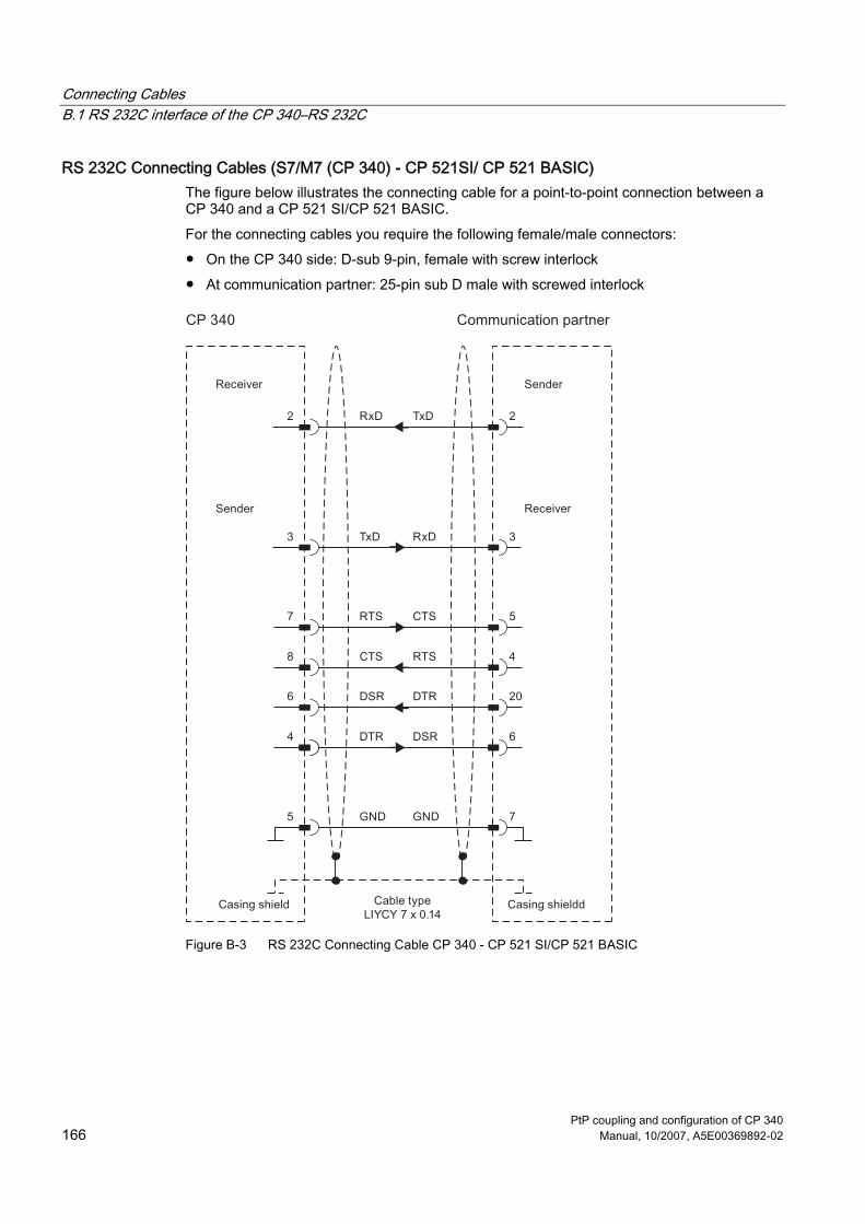
Connecting Cables B.1 RS 232C interface of the CP 340–RS 232C
PtP coupling and configuration of CP 340 166 Manual, 10/2007, A5E00369892-02
RS 232C Connecting Cables (S7/M7 (CP 340) - CP 521SI/ CP 521 BASIC) The figure below illustrates the connecting cable for a point-to-point connection between a CP 340 and a CP 521 SI/CP 521 BASIC. For the connecting cables you require the following female/male connectors: ● On the CP 340 side: D-sub 9-pin, female with screw interlock ● At communication partner: 25-pin sub D male with screwed interlock
Figure B-3 RS 232C Connecting Cable CP 340 - CP 521 SI/CP 521 BASIC

Connecting Cables B.1 RS 232C interface of the CP 340–RS 232C
PtP coupling and configuration of CP 340 Manual, 10/2007, A5E00369892-02 167
RS 232C Connecting Cables (S7/M7 (CP 340) - CP 523) The figure below illustrates the connecting cable for a point-to-point connection between a CP 340 and a CP 523. For the connecting cables you require the following female/male connectors: ● On the CP 340 side: D-sub 9-pin, female with screw interlock ● At communication partner: 25-pin sub D male with screwed interlock
Figure B-4 RS 232C Connecting Cable CP 340 - CP 523

Connecting Cables B.1 RS 232C interface of the CP 340–RS 232C
PtP coupling and configuration of CP 340 168 Manual, 10/2007, A5E00369892-02
RS 232C Connecting Cable (S7/M7 (CP 340) - DR 2xx) The figure below illustrates the connecting cable for a point-to-point connection between a CP 340 and a printer DR 2xx with serial interface. For the connecting cable you require the following female/male connectors: ● On the CP 340 side: 9-in, sub-D socket ● With DR 2xx: 25-pin sub-D male connector
Figure B-5 RS 232C connecting cable CP340-DR2xx

Connecting Cables B.1 RS 232C interface of the CP 340–RS 232C
PtP coupling and configuration of CP 340 Manual, 10/2007, A5E00369892-02 169
RS 232C Connecting Cable (S7/M7 (CP 340) - IBM-Proprinter (PT 88)) The figure below illustrates the connecting cable for a point-to-point connection between a CP 340 and an IBM-Proprinter with serial interface (PT 88 or IBM compatible printer). For the connecting cable you require the following female/male connectors: ● On the CP 340 side: 9-in, sub-D socket ● With IBM-Proprinter: 25-pin sub-D male connector
Figure B-6 RS 232C connecting cable CP340 IBM-Proprinter
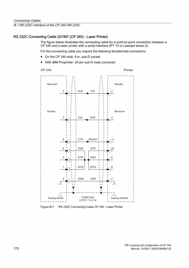
Connecting Cables B.1 RS 232C interface of the CP 340–RS 232C
PtP coupling and configuration of CP 340 170 Manual, 10/2007, A5E00369892-02
RS 232C Connecting Cable (S7/M7 (CP 340) - Laser Printer) The figure below illustrates the connecting cable for a point-to-point connection between a CP 340 and a laser printer with a serial interface (PT 10 or Laserjet series II). For the connecting cable you require the following female/male connectors: ● On the CP 340 side: 9-in, sub-D socket ● With IBM-Proprinter: 25-pin sub-D male connector
Figure B-7 RS 232C Connecting Cable CP 340 - Laser Printer

Connecting Cables B.2 20 mA TTY interface on the CP 340-20mA-TTY
PtP coupling and configuration of CP 340 Manual, 10/2007, A5E00369892-02 171
B.2 20 mA TTY interface on the CP 340-20mA-TTY
Pin assignment The table below shows the pin assignment for the 9-pin sub D socket in the front panel of the CP 340-20mA-TTY.
Table B-2 Pin assignment for the 9-pin sub D socket of the integrated interface of the CP 340-20mA-TTY
Socket to CP 340–20mA–TTY*
Pin Designation Input/Output Meaning
1 TxD - Output Transmitted data 2 20 mA - Input 5 V ground 3 20 mA + (I1) Output 20 mA current generator 1 4 20 mA + (I2) Output 20 mA current generator 2 5 RxD + Input Received data + 6 - 7 - 8 RxD - Output Received data -
9 TxD + Input Transmitted data +
* View from the front

Connecting Cables B.2 20 mA TTY interface on the CP 340-20mA-TTY
PtP coupling and configuration of CP 340 172 Manual, 10/2007, A5E00369892-02
Block diagram The figure below shows a block diagram for a 20 mA TTY interface IF963-TTY.
Figure B-8 Block diagram for the 20 mA TTY interface IF963-TTY
Connecting cables If you make your own connecting cables you must remember that unconnected inputs at the communication partner may have to be connected to open-circuit potential. Please note that you must only use shielded connector casings. A large surface area of both sides of the cable shield must be in contact with the connector casing. You are advised to use Siemens V42 254 shielded connector casings.
CAUTION Never connect the cable shield with the GND, as this could destroy the interface modules.

Connecting Cables B.2 20 mA TTY interface on the CP 340-20mA-TTY
PtP coupling and configuration of CP 340 Manual, 10/2007, A5E00369892-02 173
In the following On the following pages you will find examples of connecting cables for a point-to-point connection between the CP 340-20mA-TTY and S7 modules or SIMATIC S5.
20 mA TTY connecting cable (S7/M7 (CP 340) - S7/M7 (CP 340/CP 441) The figure below illustrates the connecting cable for a point-to-point connection between a CP 340 and a CP 340/CP 441. For the connecting cables you will require the following male connectors: ● On the CP 340 side: 9-pin sub D male connector with screw-locking ● At communication partner: 9-pin sub D male connector with screw-locking
Figure B-9 20 mA TTY connecting cable CP 340-CP 340/CP 441

Connecting Cables B.2 20 mA TTY interface on the CP 340-20mA-TTY
PtP coupling and configuration of CP 340 174 Manual, 10/2007, A5E00369892-02
20 mA TTY connecting cable (S7/M7 (CP 340) - CP 544, CP 524, CPU 928B, CPU 945, CPU 948) The figure below illustrates the connecting cable for a point-to-point connection between a CP 340 and a CP 544, CP 524, CPU 928B, CPU 945, CPU 948. For the connecting cables you will require the following male connectors: ● On the CP 340 side: 9-pin sub D male connector with screw-locking ● At communication partner: 25-pin sub D male connector with shift latch
Figure B-10 20 mA TTY connecting cable CP 340-CP 544, CP 524, CPU 928B, CPU 945, CPU 948

Connecting Cables B.2 20 mA TTY interface on the CP 340-20mA-TTY
PtP coupling and configuration of CP 340 Manual, 10/2007, A5E00369892-02 175
20 mA TTY connecting cable (S7/M7 (CP 340) - CP 523) The figure below illustrates the connecting cable for a point-to-point connection between a CP 340 and a CP 523. For the connecting cables you will require the following male connectors: ● On the CP 340 side: 9-pin sub D male connector with screw-locking ● At communication partner: 25-pin sub D male connector with screw-locking
Figure B-11 20 mA TTY connecting cable CP 340-CP 523

Connecting Cables B.2 20 mA TTY interface on the CP 340-20mA-TTY
PtP coupling and configuration of CP 340 176 Manual, 10/2007, A5E00369892-02
20 mA TTY connecting cable (S7/M7 (CP 340) - CP 521 SI/CP 521 BASIC/IBM-compatible printer) The figure below illustrates the connecting cable for a point-to-point connection between a CP 340 and a CP 521 SI/CP 521 BASIC. For the connecting cables you will require the following male connectors: ● On the CP 340 side: 9-pin sub D male connector with screw-locking ● At communication partner: 25-pin sub D male connector with screw-locking
Figure B-12 20 mA TTY connecting cable CP 340-CP 521 SI, CP 521 BASIC

Connecting Cables B.2 20 mA TTY interface on the CP 340-20mA-TTY
PtP coupling and configuration of CP 340 Manual, 10/2007, A5E00369892-02 177
20 mA TTY connecting cable (S7/M7 (CP 340) - CPU 944/AG 95) The figure below illustrates the connecting cable for a point-to-point connection between a CP 340 and a CPU 944/AG 95. For the connecting cables you will require the following male connectors: ● On the CP 340 side: 9-pin sub D male connector with screw-locking ● At communication partner: 15-pin sub D male connector with shift latch
Figure B-13 20 mA TTY connecting cable CP 340-CPU 944/AG 95

Connecting Cables B.3 X27 (RS 422/485) Interface of the CP 340–RS 422/485
PtP coupling and configuration of CP 340 178 Manual, 10/2007, A5E00369892-02
B.3 X27 (RS 422/485) Interface of the CP 340–RS 422/485
Pin assignment The table below shows the pin assignment for the 15-pin sub D socket in the front panel of the CP 340-RS 422/485.
Table B-3 Pin assignment for the 15-pin sub D socket of the integrated interface of the CP 340-RS 422/485
Socket to CP 340–RS 422/485*
Pin Designation Input/Output Meaning
1 - - - 2 T (A) Output Transmitted data (four-wire mode) 3 - - - 4 R (A)/T (A) Input
Input/output Received data (four-wire mode) Received/transmitted data (two-wire mode)
5 - - - 6 - - - 7 - - - 8 GND - Functional ground (isolated) 9 T (B) Output Transmitted data (four-wire mode) 10 - - - 11 R (B)/T (B) Input
Input/output Received data (four-wire mode) Received/transmitted data (two-wire mode)
12 - - - 13 - - - 14 - - -
15 - - -
* View from the front
Connecting cables If you make your own connecting cables you must remember that unconnected inputs at the communication partner may have to be connected to open-circuit potential. Please note that you must only use shielded connector casings. A large surface area of both sides of the cable shield must be in contact with the connector casing. You are advised to use Siemens V42 254 shielded connector casings.
CAUTION Never connect the cable shield with the GND, as this could destroy the interface modules. GND must always be connected on both sides (pin 8), otherwise the interface modules could again be destroyed.

Connecting Cables B.3 X27 (RS 422/485) Interface of the CP 340–RS 422/485
PtP coupling and configuration of CP 340 Manual, 10/2007, A5E00369892-02 179
In the following On the following pages you will find examples of connecting cables for a point-to-point connection between the CP 340-RS 422/485 and S7 modules or SIMATIC S5.
X 27 connecting cable (S7/M7 (CP 340) - CP 340/CP 441) The figure below illustrates the connecting cable for a point-to-point connection between a CP 340 and a CP 340/CP 441, for RS 422 mode. For the connecting cables you will require the following male connectors: ● On the CP 340 side: 15-pin sub D male connector with screw-locking ● At communication partner: 15-pin sub D male connector with screw-locking
Figure B-14 X27 connecting cable CP 340 - CP 441/CP 340 RS 422 mode (four wire)
Note The maximum length of this cable type at 19.2 Kbaud is 1,200 m.

Connecting Cables B.3 X27 (RS 422/485) Interface of the CP 340–RS 422/485
PtP coupling and configuration of CP 340 180 Manual, 10/2007, A5E00369892-02
X 27 connecting cable (S7/M7 (CP 340) - CP 340/CP 441) The figure below illustrates the connecting cable for a point-to-point connection between a CP 340 and a CP 340/CP 441, for RS 485 mode. For the connecting cables you will require the following male connectors: ● On the CP 340 side: 15-pin sub D male connector with screw-locking ● At communication partner: 15-pin sub D male connector with screw-locking
Figure B-15 X27 connecting cable CP 340 - CP 441/CP 340 RS 485 mode (two wire)
Note Figure B-15 shows the wiring if you want to make the connecting cable yourself. In both RS 485 mode (two wire) and RS 422 mode (four wire) you can also use Siemens connecting cables. The figure below illustrates the internal wiring in the connecting cable.

Connecting Cables B.3 X27 (RS 422/485) Interface of the CP 340–RS 422/485
PtP coupling and configuration of CP 340 Manual, 10/2007, A5E00369892-02 181
Connecting cable X 27 (S7/M7 (CP 340) - CP 544, CP 524, CPU 928B, CPU 945, CPU 948) The figure below illustrates the connecting cable for a point-to-point connection between a CP 340 and a CP 544, CP 524, CPU 928B, CPU 945, CPU 948, for RS 422 mode. For the connecting cables you will require the following male connectors: ● On the CP 340 side: 15-pin sub D male connector with screw-locking ● At communication partner: 15-pin sub D male connector with shift latch
Figure B-16 X27 connecting cable CP 340-CP 544, CP 524, CPU 928B, CPU 945, CPU 948 for
RS 422 mode

Connecting Cables B.3 X27 (RS 422/485) Interface of the CP 340–RS 422/485
PtP coupling and configuration of CP 340 182 Manual, 10/2007, A5E00369892-02
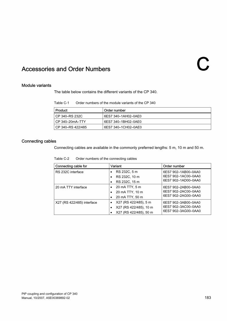
PtP coupling and configuration of CP 340 Manual, 10/2007, A5E00369892-02 183
Accessories and Order Numbers CModule variants
The table below contains the different variants of the CP 340.
Table C-1 Order numbers of the module variants of the CP 340
Product Order number CP 340–RS 232C 6ES7 340–1AH02–0AE0 CP 340–20mA–TTY 6ES7 340–1BH02–0AE0 CP 340–RS 422/485 6ES7 340–1CH02–0AE0
Connecting cables Connecting cables are available in the commonly preferred lengths: 5 m, 10 m and 50 m.
Table C-2 Order numbers of the connecting cables
Connecting cable for Variant Order number RS 232C interface • RS 232C, 5 m
• RS 232C, 10 m • RS 232C, 15 m
6ES7 902–1AB00–0AA0 6ES7 902–1AC00–0AA0 6ES7 902–1AD00–0AA0
20 mA TTY interface • 20 mA TTY, 5 m • 20 mA TTY, 10 m • 20 mA TTY, 50 m
6ES7 902–2AB00–0AA0 6ES7 902–2AC00–0AA0 6ES7 902–2AG00–0AA0
X27 (RS 422/485) interface • X27 (RS 422/485), 5 m • X27 (RS 422/485), 10 m • X27 (RS 422/485), 50 m
6ES7 902–3AB00–0AA0 6ES7 902–3AC00–0AA0 6ES7 902–3AG00–0AA0

Accessories and Order Numbers
PtP coupling and configuration of CP 340 184 Manual, 10/2007, A5E00369892-02
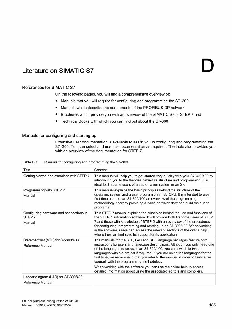
PtP coupling and configuration of CP 340 Manual, 10/2007, A5E00369892-02 185
Literature on SIMATIC S7 DReferences for SIMATIC S7
On the following pages, you will find a comprehensive overview of: ● Manuals that you will require for configuring and programming the S7–300 ● Manuals which describe the components of the PROFIBUS DP network ● Brochures which provide you with an overview of the SIMATIC S7 or STEP 7 and ● Technical Books with which you can find out about the S7-300
Manuals for configuring and starting up Extensive user documentation is available to assist you in configuring and programming the S7–300. You can select and use this documentation as required. The table also provides you with an overview of the documentation for STEP 7.
Table D-1 Manuals for configuring and programming the S7–300
Title Content Getting started and exercises with STEP 7 This manual will help you to get started very quickly with your S7-300/400 by
introducing you to the theories behind its structure and programming. It is ideal for first-time users of an automation system or an S7.
Programming with STEP 7 Manual
This manual explains the basic principles behind the structure of the operating system and a user program on an S7 CPU. It is intended to give first-time users of an S7-300/400 an overview of the programming methodology, thereby providing a basis on which they can build their user programs.
Configuring hardware and connections in STEP 7 Manual
This STEP 7 manual explains the principles behind the use and functions of the STEP 7 automation software. It will provide both first-time users of STEP 7 and those with knowledge of STEP 5 with an overview of the procedures for configuring, programming and starting up an S7-300/400. When working in the software, users can access the relevant sections of the online help where they will find specific support for its application.
Statement list (STL) for S7-300/400 Reference Manual
The manuals for the STL, LAD and SCL language packages feature both instructions for users and language descriptions. Although you only need one of the languages to program an S7-300/400, you can switch between languages within a project if required. If you are using the languages for the first time, we recommend that you refer to the manual in order to familiarize yourself with the programming methodology. When working with the software you can use the online help to access detailed information about using the associated editors and compilers.
Ladder diagram (LAD) for S7-300/400 Reference Manual
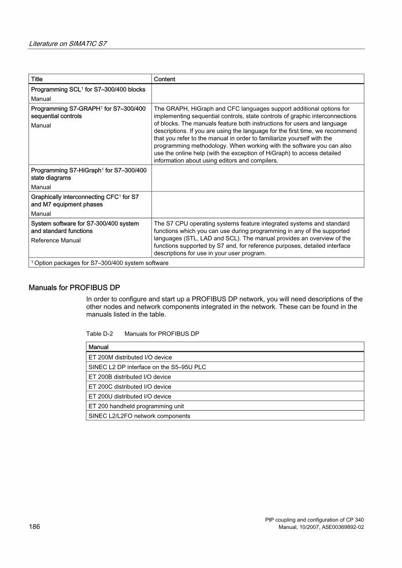
Literature on SIMATIC S7
PtP coupling and configuration of CP 340 186 Manual, 10/2007, A5E00369892-02
Title Content Programming SCL1 for S7–300/400 blocks Manual
Programming S7-GRAPH1 for S7–300/400 sequential controls Manual
The GRAPH, HiGraph and CFC languages support additional options for implementing sequential controls, state controls of graphic interconnections of blocks. The manuals feature both instructions for users and language descriptions. If you are using the language for the first time, we recommend that you refer to the manual in order to familiarize yourself with the programming methodology. When working with the software you can also use the online help (with the exception of HiGraph) to access detailed information about using editors and compilers.
Programming S7-HiGraph1 for S7–300/400 state diagrams Manual
Graphically interconnecting CFC1 for S7 and M7 equipment phases Manual
System software for S7-300/400 system and standard functions Reference Manual
The S7 CPU operating systems feature integrated systems and standard functions which you can use during programming in any of the supported languages (STL, LAD and SCL). The manual provides an overview of the functions supported by S7 and, for reference purposes, detailed interface descriptions for use in your user program.
1 Option packages for S7–300/400 system software
Manuals for PROFIBUS DP In order to configure and start up a PROFIBUS DP network, you will need descriptions of the other nodes and network components integrated in the network. These can be found in the manuals listed in the table.
Table D-2 Manuals for PROFIBUS DP
Manual ET 200M distributed I/O device SINEC L2 DP interface on the S5–95U PLC ET 200B distributed I/O device ET 200C distributed I/O device ET 200U distributed I/O device ET 200 handheld programming unit SINEC L2/L2FO network components
Literature on SIMATIC S7
PtP coupling and configuration of CP 340 Manual, 10/2007, A5E00369892-02 187
Brochures The table lists brochures which will provide you with an overview of the S7-300, STEP 7 and distributed I/Os in S7/M7.
Table D-3 Brochures for SIMATIC S7, STEP 7 and PROFIBUS DP
Brochures S7-300 automation system - Design and application From SIMATIC S5 to SIMATIC S7 - A guide to simplify transition Programming S7–300/400 automation systems S7/M7 automation systems - Distribution with PROFIBUS DP and AS–I

Literature on SIMATIC S7
PtP coupling and configuration of CP 340 188 Manual, 10/2007, A5E00369892-02

PtP coupling and configuration of CP 340 Manual, 10/2007, A5E00369892-02 189
Glossary
Address The address indicates the physical storage space and enables direct access to the operand that is stored under this address.
Block Blocks are parts of the user program that are separated *** by their function, structure or purpose. STEP 7 has the following blocks: ● Code blocks (FB, FC, OB SFB, SFC) ● Data blocks (DB, SDB) and ● user-defined data types (UDT)
Block call A block call is the branching of the program processing into the called block.
Block parameter Block parameters are place holders within multiple use blocks, which are supplied with updated valves during the calling up of the corresponding block.
Communications processor Communications processors are modules for point-to-point connections and bus connections
Configuring Configuring refers to the configuration of separate modules of a programmable controller in the configuration table.
CP 340 programming interface: Point-to-Point Communication, Parameter Assignment interface Using the CP 340: Point-to-Point Communication, Parameter Assignment interface you can parameterize the interface of the communications processor and configure the message texts for the printer output.

Glossary
PtP coupling and configuration of CP 340 190 Manual, 10/2007, A5E00369892-02
CPU Central Processing Unit = Central module of the S7 Programmable Controller with control and computing unit, memory, system program and interfaces to the I/O modules.
Cycle time The cycle time is the time that the CPU requires to process the user program once.
Cyclic program processing In cyclic program processing the user program runs in program loop, or cycle, that is constantly repeated.
Data block (DB) Data blocks are blocks that contain data and parameters with which the user program works. Unlike all other blocks, they do not contain any instructions. There are global data blocks and instance data blocks. The data contained in the data blocks can be accessed absolutely or symbolically. Complex data can be stored in structured form.
Data Type With the help of the data types you can specify how the value of a variable or constant in the user program is to be used. The data types are divided into elementary and structured data types
Default setting T'he default setting is a reasonable basic setting that can be used whenever no other value is specified.
Diagnostic buffer Each CPU has its own diagnostic buffer, in which detailed information on all the diagnostic events are entered in the sequence in which they occur. The CP 340 has its own diagnostic buffer in which all diagnostic events of the CP 340 are entered (hardware/firmware errors, initialization/parameterization errors, sending and receiving errors).
Diagnostic events Diagnostic events are such as module errors, system errors in the CPU which may be caused by a program errror or transitions from one operating mode to another.
Diagnostics functions The diagnostic functions cover the entire system diagnostics and include the recognition, interpretation and reporting of errors within the Programmable Controller.

Glossary
PtP coupling and configuration of CP 340 Manual, 10/2007, A5E00369892-02 191
Function blocks (FBs) Function blocks are components of the user program and are, according to IEC standard, "blocks with memory". The memory for the function blocks is an allocated data block, the "instance data block". Function blocks can be parameterized, i.e. you can use them with and without parameters.
Hardware Hardware is the entire physical and technical equipment of a programmable controller.
Instance data block The instance data block is a block allocated to a function block, which contains data for this special function block.
Interrupt Interrupt is a term that designates the interruption of the processing of a program in the processor of a programmable controller by an external alarm
Loading from PC Downloading of load objects (e.g. code blocks) from the programming device into the load memory of the central processing unit (CPU).
Loading in the programming device Uploading of load objects (e.g. code blocks) from the load memory of the central processing unit into the programming device.
Module Modules are pluggable PCBs for programmable controllers.
Module parameters Module parameters are values with which the behavior of the module can be set. There are two different types of module parameters: static and dynamic.
Mounting rack The mounting rack is the rail containing the slots for the modules.
Online Help STEP 7 provides you with the option of having context-dependant help texts displayed on the screen while you are working with the programming software.

Glossary
PtP coupling and configuration of CP 340 192 Manual, 10/2007, A5E00369892-02
Online/Offline When you are online there is a data connection between the programmable controller and programming device, when you are offline there is no data connection between them.
Operand An operand is part of a STEP-7 instruction and states with which unit the process should execute something. It can be addressed both absolutely and symbolically.
Operating mode The SIMATIC S7 programmable controllers have three different operating modes: STOP, START-UP and RUN. The functionality of the CPU is different in the various operating modes.
Operating system of the CPU The operating system of the CPU organizes all the functions and process of the CPU that are not connected to a special control task.
Parameterization Parameterization refers to the setting of a module's behavior.
Parameters Parameters are values that can be allocated. There are two different types of parameters: block parameters and module parameters.
Point-to-point communication In point-to-point communication the communications processor forms the interface between a programmable controller and a communication partner.
Procedure Procedure refers to the process of a data transmission according to a specific protocol.
Process image The process image is a special memory area in the programmable controller. At the start of the cyclic program the signal states of the input modules are transmitted to the process image of the inputs. At the end of the cyclic program the process image of the outputs is transmitted as signal state to the output modules.

Glossary
PtP coupling and configuration of CP 340 Manual, 10/2007, A5E00369892-02 193
Programmable Controller A programmable controller is a stored-program control consisting of at least one CPU, various input and output modules, and operating and monitoring devices
Protocol All communication partners involved in data transmission must follow fixed rules for handling and implementing the data traffic. Such rules are called protocols.
S7-300 backplane bus The S7-300 backplane bus is a serial data bus via which the modules communicate with each other and via which they are supplied with the necessary voltage.
Software Software refers to the entirety of all programs that are used on a computing system. The operating system and user programs belong to this.
START-UP The START-UP operating mode forms the transition from STOP mode to RUN mode.
STEP 7 STEP 7 is the programming software of SIMATIC S7.
System blocks System blocks are different from other block in that they are already integrated into the S7-300 system and are available for already defined system functions. There are system data blocks, system functions and system function blocks.
System function blocks (SFBs) System functions are blocks without memory that are already integrated into the operating system of the CPU and can be called up by the user whenever necessary.
System functions (SFCs) System functions are blocks without memory that are already integrated into the operating system of the CPU and can be called up by the user whenever necessary.
User program The user program contains all instructions and declarations for processing the signals used for controlling a system or a process. In SIMATIC S7 the user program is structured and divided into small units, the blocks.
Glossary
PtP coupling and configuration of CP 340 194 Manual, 10/2007, A5E00369892-02
Variable A variable is an operand (e.g. I 1.0) which can have a symbolic name and therefore also be addressed symbolically.
Working Memory The working memory is a RAM storage unit in the CPU which the processor draws on when running the user program.
PtP coupling and configuration of CP 340 Manual, 10/2007, A5E00369892-02 195
Index
2 20mA-TTY, 18 20mA-TTY interface
Technical data, 158
3 3964(R) procedure
Baud rate, 57 Character frame, 57 Handling errored data, 40 Technical data, 159
3964(R) protocol, 55
A ASCII driver, 46
BREAK evaluation, 52 Code Transparency, 48 Data flow control, 61 End criteria, 48 Parameter, 59 Parameterization data, 59 Receive buffer, 62 RS 232C accompanying signals, 43 Sending, 47 Technical data, 160 X27 (RS 422/485) interface, 62
Assignment of new parameters, 127
B BREAK evaluation, 52 Bus connector for the S7 backplane bus, 16 BUSY signal, 33
C Calling the SFCERR or SFCSTATUS variable, 139 Code Transparency, 48 Configuring the CP 340, 88
Connecting Cables RS 232C, 164
CP 340 Parameter assignment, 86 Technical data, 157
CP 340 slots, 81 CPU RUN, 129 CPU Startup, 129 CPU-STOP, 129
D Data block assignment, 120 Data flow control, 33 Diagnostic buffer of the CP 340, 142 Diagnostic Buffer of the CP 340, 131 Diagnostics
Diagnostic buffer, 142 Diagnostics functions
Diagnostics interrupt, 140 Diagnostics functions of the CP 340
Diagnosis via display elements, 131 Diagnosis via the S7-300 backplane bus, 131 Diagnostics by means of the diagnostic buffer, 131 Diagnostics via the STATUS output, 131
Diagnostics interrupt, 53 Display elements (LED), 131 Disposal of the CP 340, 162
F FB 2 P_RCV
Parameters, 106 Time Sequence Chart, 107
FB 4 P_PRINT Parameters, 111 Time Sequence Chart, 112
FC 5 V24_STAT Parameters, 115
FC 6 V24_SET Parameters, 116
Firmware update, 92 Function block, 98
FB 2 P_RCV, 106

Index
PtP coupling and configuration of CP 340 196 Manual, 10/2007, A5E00369892-02
FB 4 P_PRINT, 108 Installation, 99 Memory requirements, 95 Overview, 99 P_PRINT FB, 108 P_RCV FB, 104, 105 P_RESET FB, 117 P_SEND (FB 3), 102 P_SEND FB, 100
G Group error displays, 132
H Handshaking, 45 Hardware Components, 13
I Identification data
Definition, 92 Installing the communication processor, 79 Installing the CP 340, 82 Interface
20mA-TTY, 18 RS 232C, 17, 18 X27 (RS 422/485), 19
Interface types, 16 Interrupt behavior, 126 ISO 7-Layer Reference Model, 27
M Managing the parameter data, 89 Message frames, 130 Message texts
Formatting, 69 Variables, 69
Module variants, 11 CP 34x–20mA-TTY, 11 CP 34x–RS 232C, 11 CP 34x–RS 422/485, 11 Functions, 12
Mounting rack, position, 81
O Operating mode transitions, 129
Operating modes, 127 Assignment of new parameters, 127 RUN, 127 STOP, 127
Order numbers Connecting cables, 183
Order numbers Module variants, 183
P P_PRINT FB
Assignment in the Data Area, Pointer DB, 110 Instance DB, 109 Message Texts, 108
P_RCV FB Assignment in the Data Area, 105
P_RESET FB Assignment in the data area, 118 Block call, 117 Delete receive buffer, 117 Error display, 117 Parameters, 118 Time sequence chart, 119
P_SEND (FB 3) Parameters, 102 Time Sequence Chart, 103
P_SEND FB Assignment in the Data Area, 102
Parameter assignment user interface Installing, 87
Parameterization Block parameter, 122 Examples, 122
Parameterization data 3964(R) procedure, 54 ASCII driver, 59
Point-to-point communication Hardware Components, 13 Software Components, 14
Possible applications for the CP 340, 12 Printer driver
Baud rate, 64 BUSY signal, 33 Character frame, 64 Character set, 67 Control characters, 67 Data flow control, 33, 65 Examples, 31 Format string, 31 Handshaking, 33 Message texts, 30, 68

Index
PtP coupling and configuration of CP 340 Manual, 10/2007, A5E00369892-02 197
Technical data, 161 Variables, 30 X27 (RS 422/485) interface, 66
Procedure, 26 Programming device, 14 Programming example, 145
R Reading the diagnostic buffer at the programming device, 142 Receive buffer on CP 340, 52 Receiving message frames, 130 Recycling, 162 Removing the CP 340, 82, 83 RS 232C, 17 RS 232C accompanying signals, 43
Automatic control, 44 V24_SET FC, 43 V24_STAT FC, 43
RS 232C interface Technical data, 158
RS 232C Interface Connecting Cables, 163 Pinout, 163
RS 232C Secondary Signals, 113 Reading and controlling, 113
RXD, 132
S S7-300 backplane bus, 131 Service & Support, 5 Software Components, 14
Function blocks, 14
Parameterization interface, 14 STEP 7 software package, 14
Special displays, 132 Standard connecting cable, 13 Standard Connecting Cable, 13 Start-up behavior, 128 STATUS Output of the FBs, 131 STATUS parameter
Event classes, 133 Example, 133 Structure, 133
T Technical data, 157 The program example
Download to the CPU, 153 TXD, 132
V V24_SET FC, 43 V24_STAT FC, 43
X X27 (RS 422) interface
Parameter, 58 X27 (RS 422/485), 19 X27 (RS 422/485) interface
Technical data, 158

Index
PtP coupling and configuration of CP 340 198 Manual, 10/2007, A5E00369892-02


