Hazard Analysis for the Pretreatment Engineering … Rev. 0 Hazard Analysis for the Pretreatment...
141
PNNL-16755 Rev. 0 Hazard Analysis for the Pretreatment Engineering Platform (PEP) RS. Sullivan WE Lawrence JGH Geeting J Young June 2008 Prepared for the U.S. Department of Energy under Contract DE-AC05-76RL01830
Transcript of Hazard Analysis for the Pretreatment Engineering … Rev. 0 Hazard Analysis for the Pretreatment...

PNNL-16755 Rev. 0
Hazard Analysis for the Pretreatment Engineering Platform (PEP) RS. Sullivan WE Lawrence JGH Geeting J Young June 2008 Prepared for the U.S. Department of Energy under Contract DE-AC05-76RL01830

DISCLAIMER This report was prepared as an account of work sponsored by an agency of the United States Government. Neither the United States Government nor any agency thereof, nor Battelle Memorial Institute, nor any of their employees, makes any warranty, express or implied, or assumes any legal liability or responsibility for the accuracy, completeness, or usefulness of any information, apparatus, product, or process disclosed, or represents that its use would not infringe privately owned rights. Reference herein to any specific commercial product, process, or service by trade name, trademark, manufacturer, or otherwise does not necessarily constitute or imply its endorsement, recommendation, or favoring by the United States Government or any agency thereof, or Battelle Memorial Institute. The views and opinions of authors expressed herein do not necessarily state or reflect those of the United States Government or any agency thereof.
PACIFIC NORTHWEST NATIONAL LABORATORY operated by BATTELLE
for the UNITED STATES DEPARTMENT OF ENERGY
under Contract DE-AC05-76RL01830
Printed in the United States of America
Available to DOE and DOE contractors from the Office of Scientific and Technical Information,
P.O. Box 62, Oak Ridge, TN 37831-0062; ph: (865) 576-8401 fax: (865) 576-5728
email: [email protected]
Available to the public from the National Technical Information Service, U.S. Department of Commerce, 5285 Port Royal Rd., Springfield, VA 22161
ph: (800) 553-6847 fax: (703) 605-6900
email: [email protected] online ordering: http://www.ntis.gov/ordering.htm
This document printed on recycled paper.

PNNL-16755 Rev. 0
Hazard Analysis for the Pretreatment Engineering Platform (PEP)
R. S. Sullivan J. G. H. Geeting W. E. Lawrence J. Young June 2008 Prepared for the U.S. Department of Energy under Contract DE-AC05-76RL01830 Pacific Northwest National Laboratory Richland, WA 99354

iii
Summary The Pretreatment Engineering Platform (PEP) is designed to perform a demonstration on an engineering scale to confirm the Hanford Waste Treatment Plant Pretreatment Facility (PTF) leaching and filtration process equipment design and sludge treatment process. The system will use scaled prototypic equipment to demonstrate sludge water wash, caustic leaching, oxidative leaching, and filtration. Unit operations to be tested include pumping, solids washing, chemical reagent addition and blending, heating, cooling, leaching, filtration, and filter cleaning. In addition, the PEP will evaluate potential design changes to the ultrafiltration process system equipment to potentially enhance leaching and filtration performance as well as overall pretreatment throughput. The skid-mounted system will be installed and operated in the Processing Development Laboratory-West at Pacific Northwest National Laboratory (PNNL) in Richland, Washington. This document identifies potential industrial safety, environmental, and cost impacts associated with the PEP and the safeguards needed to provide protection against them. This information has been produced by performing a series of hazard analyses at the 30%, 90%, and 100% designs for the PEP. The hazard analyses address the PEP process equipment, intended operating activities, and anticipated maintenance and testing. Three hazard analysis methodologies were used during this process, a Hazard Identification Checklist to identify all of the energy sources and material-at-risk present at and near the facility, a Hazard and Operability (HAZOP) study to address the process design, and a Preliminary Hazards Analysis (PHA) to address process activity integration with Processing Development Laboratory-West. Several recommendations were generated during the hazard analyses studies. These recommendations fell into three categories:
Develop additional information on the design, operation, or maintenance of PEP to support completion of the hazard analysis.
Perform engineering analyses to confirm design assumptions or bases.
Provide additional safeguards not identified in the 30% design package or intended operating scheme.
All recommendations were reviewed/resolved by the project by the time the final 100% design analysis sessions were complete.

v
Acronyms BNI Bechtel National Inc. CXP cesium ion exchange process FEP feed evaporator producer FRP feed receipt vessel HAZOP Hazard and operability study HLW high-level waste LAW low-activity waste MAR material at risk PDL-W Processing Development Laboratory-West PEP Pretreatment Engineering Platform PHA Preliminary Hazard Analysis PJM pulse jet mixers PNNL Pacific Northwest National Laboratory PTF Hanford Pretreatment Facility TDS total dissolved solids TKS Tessenderlo Kerley Services TMP transmembrane pressure UFP ultrafiltration feed preparation WGI Washington Group Inc. WTP Waste Treatment Plant


vii
Contents
Summary ...................................................................................................................................................... iii Acronyms...................................................................................................................................................... v 1.0 Introduction................................................................................................................................. 1.1 2.0 System Description ..................................................................................................................... 2.1
2.1 Facility/System Description ........................................................................................................ 2.1 2.1.1 Exterior Structure ................................................................................................................. 2.1 2.1.2 Interior Structure .................................................................................................................. 2.2 2.1.3 Building Utilities .................................................................................................................. 2.2
2.2 Process Description..................................................................................................................... 2.3 2.2.1 Upfront Leaching ................................................................................................................. 2.4 2.2.2 Leaching in UFP-VSL-T02A............................................................................................... 2.9 2.2.3 Ultrafilter Cleaning Cycle .................................................................................................. 2.10
3.0 Hazard Analysis Methods ........................................................................................................... 3.1 3.1 Hazard Identification................................................................................................................... 3.1 3.2 Hazard Evaluation....................................................................................................................... 3.1
3.2.1 Hazards Analysis Worksheets.............................................................................................. 3.2 3.2.2 Likelihood Category Definitions.......................................................................................... 3.3 3.2.3 Consequence Category Definitions...................................................................................... 3.4 3.2.4 Environmental Category ...................................................................................................... 3.5 3.2.5 Risk Score ............................................................................................................................ 3.5
4.0 Hazard Analysis Results ............................................................................................................. 4.1 4.1 Hazard Analysis Sessions ........................................................................................................... 4.1 4.2 Hazard Identification and MAR Definition ................................................................................ 4.2 4.3 Nodal Decomposition ................................................................................................................. 4.3 4.4 Assumptions................................................................................................................................ 4.3 4.5 Results......................................................................................................................................... 4.3
5.0 Safeguards................................................................................................................................... 5.1 6.0 References................................................................................................................................... 6.1 Appendix A Meeting Attendees............................................................................................................... A.1 Appendix B Hazard Analysis Nodalization ..............................................................................................B.1 Appendix C HAZOP Deviation Guide .....................................................................................................C.1 Appendix D Hazard Identification Checklist........................................................................................... D.1 Appendix E Hazard Analysis Worksheets ................................................................................................E.1 Appendix F Recommendations.................................................................................................................F.1 Appendix G Safeguard Allocation........................................................................................................... G.1 Appendix H Peer Review Form............................................................................................................... H.1

viii
Figures
2.1. Process Development Laboratory-West............................................................................................. 2.1
2.2. Simplified Flow Diagram of Engineering Scaled Pretreatment System............................................ 2.5
2.3. Normal Operation of Ultrafilter Module and Permeate Process Diagram ....................................... 2.12
Tables
3.1. Likelihood Category Definitions ....................................................................................................... 3.3
3.2. Health and Safety Consequence......................................................................................................... 3.4
3.3. Financial Consequence ...................................................................................................................... 3.4
3.4. Environmental Consequence.............................................................................................................. 3.5
3.5. Risk Score .......................................................................................................................................... 3.5
3.6. Safeguard Score ................................................................................................................................. 3.6
4.1. Hazard Analysis Assumptions/Ground Rules.................................................................................... 4.4
5.1. PEP Credited Safeguards ................................................................................................................... 5.2

1.1
1.0 Introduction This document identifies potential industrial safety, environmental, and cost impacts associated with the Hanford Waste Immobilization and Treatment Plant (WTP) Pretreatment Engineering Platform (PEP) and the safeguards needed to provide protection against them. The skid-mounted system will be installed and operated in the Processing Development Laboratory (PDL)-West facility at Pacific Northwest National Laboratory (PNNL) in Richland, Washington. This information has been produced by performing a series of hazard analyses at the 30%, 90% and 100% designs of the PEP (TKS 2007a,b,c). The purpose is to support the evolving design of the process equipment and development of operating and maintenance procedures for PEP as it will be operated and maintained in PDL-West. The hazard analyses address the PEP process equipment, intended operating activities and anticipated maintenance and testing. The analyses consider the integration of PEP in PDL-West. Potential industrial safety issues, environmental releases, and cost impacts are addressed in the analyses. The cost of shutdown of PEP due to the need to replace major process system hardware is not addressed in the assessment of cost impacts. The analyses results included 1) identification of safeguards to manage safety; 2) recommendations to reduce risk, environmental releases, or costs; and/or 3) verification of design and operating assumptions. All recommendations were reviewed/resolved by the project by the time the 100% design analysis sessions were complete. The PEP is designed to perform a demonstration on an engineering scale to confirm the Hanford Pretreatment Facility (PTF) leaching and filtration process equipment design [ultrafiltration feed preparation (UFP) system] and sludge treatment process flow sheet. The system will be designed using scaled prototypic equipment to demonstrate sludge water wash, caustic leaching, oxidative leaching, and filtration. The unit operations to be tested include pumping, solids washing, chemical reagent addition and blending, heating, cooling, leaching, filtration, and filter cleaning. In addition, the PEP will evaluate potential design changes to the UFP system leaching and ultrafiltration equipment as determined from engineering studies to potentially enhance leaching and filtration performance as well as overall pretreatment throughput. The skid-mounted system will be installed into the PDL-W.

2.1
2.0 System Description
2.1 Facility/System Description The PDL-W Building is a 6,826-square-foot building built in 1981 to provide high-bay space for high-temperature, high-pressure research on the expansion of metals by the PNNL Materials Group. It consists primarily of office and laboratory areas. The PDL-W building layout is shown in Figure 2.1.
Figure 2.1. Process Development Laboratory-West
2.1.1 Exterior Structure This facility is primarily a high-bay structure constructed on concrete foundations and concrete slab-on-grade floors. The building is steel framed and covered with prefabricated, insulated, galvanized steel-ribbed panels. It has a built-up flat roof. The high-bay area contains four load cells that are shrouded and

2.2
capable of maintaining high temperatures and pressures. Connected to the high bay is a smaller building of similar structure that includes dry laboratories, a mechanical equipment room, and a restroom.
2.1.2 Interior Structure The interior space where offices and lobby are located is constructed of gypsum wallboard with suspended ceiling tiles. The east wall of the office area is constructed of painted concrete blocks. There are 12 × 12-inch floor tiles in the hallway and vinyl sheeting material in the restrooms; offices have carpeting on the floors. Where rooms have been carpeted, the carpet may have been laid over the tile. The high-bay area has a painted concrete floor and metal insulated walls and ceiling. The west wall is painted concrete block.
2.1.3 Building Utilities The electric power capacity is supplied by one 1000-kVA City of Richland transformer. The main electrical panel is a 750-amp, 277/480-V, 3-phase, 4-wire service. A 400-amp, 277/480-V, 3-phase breaker services the east buss duct, and a 400-amp, 277/480-V, 3-phase breaker services the west buss duct. There is 120/208-V service throughout the entire building and 480-V to the high bay. There is no backup/standby power. The HVAC for the building consists of the following:
The heating capacity for the office area is supplied by a gas-fired, 2000-cfm, 92,000-Btu/hr heating capacity, 5.5-ton heat pump with a three-stage, 20-kW heating coil, 68,240 Btu/hr. The high bay has two 250,000 Btu/hr wall heaters.
The cooling for the office area is supplied by a 2000-cfm, 57,000 Btu/hr cooling capacity, 5.5-ton heat pump. The high bay has two 10-ton Trane air-conditioning units of 120,000 Btu/hr each.
HVAC setback schedule for the office and high bay is Monday through Friday, 6:00 pm to 5:00 am and all weekend.
The standard temperature control range (non-setback) is 60° to 80°F.
There are 6 air exchanges per hour for the office area; for the high bay there are 0 to 10. Process and sanitary water is supplied by a 3-inch main line from the City of Richland. Two backflow preventers are provided with the water service.
Process water is supplied at 200 gpm maximum.
There is no reverse osmosis or deionized water capacity. There is no laboratory manifold gas supply and capacity.
Laboratory compressed air is delivered at 100 psi from a 10 hp air compressor with a 30 scfm capacity.
No laboratory vacuum capacity exists.

2.3
Fire Zones: A Fire Zone “Control Area” is a building or portion of a building within which the exempted amounts of hazardous materials are allowed to be stored, dispensed, used, or handled, or which may provide extended fire protection to unique and/or valuable equipment.
Areas of coverage: Zone 1 102, 103, 104, 105, 106A, 106B, 106C, 106D, high bay Zone 5 PRMTR (areas within 5 ft of bldg) Zone 6 OUTSD (areas outside 5 ft of bldg)
Zone Occupancy Class Sprinklers (Yes/No)
Zone 1 Dry Laboratory(a) Yes Zone 5 Outside Storage No Zone 6 Outside Storage No
(a) The PDL-W is a high-bay building that involves pilot-scale research projects. This occupancy is unique in that it is not suitable for wet chemistry laboratory operations. However, the research performed in the building can involve larger quantities of hazardous materials due to the scale of the projects. All projects incorporate engineering controls equivalent to those provided in wet chemistry occupancies for the hazard of the materials involved.
Air and liquid effluent control systems present are the following:
Air: None (ventilation for HVAC in the high bay will be increased to approximately 40,000 cfm and will be handled by one or two variable-speed fans mounted on the roof).
Liquid: Sanitary sewer system Floor loading for the building consists of:
Offices, restrooms: 100 lb/ft2
Corridors, lobby, stairways: 100 lb/ft2
Labs: 250 lb/ft2
Secondary containment: The whole high-bay floor was modified to serve as a secondary containment system.
Natural gas: The natural gas supply is approximately 3,000,000 Btu/hr.
2.2 Process Description The following sections provide a description of the normal process operation and major equipment with an explanation of functions and required plant services. The process description is derived from the Performance Requirements for Engineering Scale Pretreatment System (24590-PTF-3YD-UFP-00002 Rev. 1). Figure 2.2 is a simplified flow diagram of the UFP system with its associated components.

2.4
2.2.1 Upfront Leaching
2.2.1.1 High-Level Waste Simulant Receipt Vessel, HLP-VSL-T22 The HLW receipt vessel receives HLW simulant. This vessel also acts as the “feed forward” vessel and may receive LAW simulant and evaporator recycles from FRP-VSL-T01 and FEP-VSL-T01, respectively. The feed is fed forward to UFP-VSL-T01A or B. For flexibility, the vessel contents can be recycled to FEP-VSL-T01. The vessel is equipped with a variable frequency drive mechanical agitator to mix the simulant. The energy of the mixing can be varied to characterize the simulant as homogeneous or stratified, depending on the test requirements. The vessel will be sampled before any transfers out of the vessel are performed. Sampling may include determining requirements for leaching, amount of caustic to add for leaching (which can be added in-line during transfers), and the ratio of HLW to LAW feed simulant to blend in UFP-VSL-T01A/B. The vessel has the capability to heat the simulant. The purpose of the heating function is to simulate the waste feed evaporator holdup time and upfront leaching. The waste feed evaporator is expected to be operated at approximately 55°C; therefore, this vessel is equipped with a heating jacket. The vessel is equipped with temperature, level, and pressure measurements to monitor process conditions. The contents of the vessel are transferred out of the vessel by a pump that is equipped with a variable frequency drive. The contents can be transferred to UFP-VSL-T01A/B or FEP-VSL-T01. The vessel is also equipped with a bottom drain and is piped to UFP-VSL-T62A for evaporation considerations.

2.52.5
UFP-VSL-T01AUFP-PMP-T41A
UFP-PMP-T41B
19M NaOHReagents
LAW Feed(FRP)
UFP-VSL-T02AUFP-PMP-T43A
PermeateVessel
UFP-VSL-T62B
PermeateVessel
UFP-VSL-T62A
InhibitedWater
(Dilution)
Ultrafilters
UF FeedPreparation
Vessel
UFP-VSL-T01B
UF FeedPreparation
Vessel
UF FeedVessel
Inhibited Water (Solids Washing)
ReagentsHLW Feed(HLP)
UFP-HX-T02A
Spiral HeatExchanger
UFP-HX-T03A
UFP-PMP-T42A
UFP-HX-T04B
UFP-HX-T05B
UFP-HX-T04A
UFP-HX-T05A
Reagents
Inhibited Water (Solids Washing)
HLWSolids
Storage
HLP-VSL-T27A
LAWReceiptVessel
FRP-VSL-T01
EvapProductVessel
FEP-VSL-T01
HLWReceiptVessel
HLP-VSL-T22
FEP-PMP-T01FRP-PMP-T01
HLP-PMP-T21
Figure 2.2. Simplified Flow Diagram of Engineering Scaled Pretreatment System

2.6
2.2.1.2 LAW Simulant Receipt Vessel, FRP-VSL-T01
The LAW receipt vessel receives LAW simulant and may also receive evaporator recycles from FEP-VSL-T01. The vessel is equipped with a variable frequency drive mechanical agitator to mix the simulant. The energy of the mixing can be varied to characterize the simulant as homogenous or stratified, depending on the test requirements. The vessel will be sampled before any transfers out of the vessel are performed. Sampling may include determining requirements for leaching, amount of caustic to add for leaching, and the ratio of HLW to LAW feed simulant to blend in UFP-VSL-T01A/B. The vessel is designed to provide the same design functions as HLP-VSL-T22, with the capability to add a steam jacket in the future. The vessel is equipped with temperature, level and pressure measurements to monitor process conditions. The contents of the vessel are transferred out of the vessel by a pump that is equipped with a variable frequency drive. The contents can be transferred to HLP-VSL-T22 or to FEP-VSL-T01. The vessel is also equipped with a bottom drain which may be sent to UFP-VSL-T62A for evaporation considerations. 2.2.1.3 Feed Evaporator Producer Product Vessel, FEP-VSL-T01
The FEP product vessel is used as a backup feed receipt vessel and as a recycle hold vessel to provide extra lag storage when required. Recycles received in this vessel may include solids washing permeate, leach permeate, concentration permeate and various rinse water or spent cleaning reagents. The vessel may receive LAW simulant from FRP-VSL-T01, HLW simulant from HLP-VSL-T22 and recycles from UFP-VSL-T62B. The vessel will be designed to provide the same design functions as HLP-VSL-T22, with the capability to add a steam jacket in the future. The vessel is equipped with a variable frequency drive mechanical agitator to mix the simulant. The energy of the mixing can be varied to characterize the simulant as homogenous or stratified depending on the test requirements. The vessel will be equipped with sampling capabilities. Sampling may include determining requirements for leaching, amount of caustic to add for leaching, and the ratio of HLW to LAW feed simulant to blend in UFP-VSL-T01A/B. Sampling may also be used for recycle solution to determine post precipitation of aluminum and other leached species which is collected in the permeate product. In order to monitor the process conditions in the vessel, the vessel is equipped with temperature, level and pressure instruments. A pump that has a variable frequency drive transfers out the contents of the vessel. The contents can be transferred to HLP-VSL-T22 or to FRP-VSL-T01. The vessel is also equipped with a bottom drain which may be connected to UFP-VSL-T62A for evaporation considerations. 2.2.1.4 Ultrafiltration Feed Preparation Vessel, UFP-VSL-T01A/B
The ultrafiltration system is a batch system that requires a constant source of feed from UFP-VSL-T01A or B transferred to UFP-VSL-T02A. Therefore, for most ultrafiltration cycles consisting of producing 20 wt% solids, multiple batches of feed will be required to support ultrafiltration. To accomplish this the vessels UFP-VSL-T01A/B will likely operate on alternate phases, with one vessel receiving waste from HLP-VSL-T22 while the other vessel is either performing caustic leaching (if upfront leaching is required) or is in discharge mode. If caustic leaching is required, the vessel will undergo heating and digest modes before being placed in discharge mode. Once a vessel is in discharge mode, the vessel will feed small batches of waste to UFP-VSL-T02A as required. As the feed is transferred, the slurry is cooled to the filtering temperature as necessary. Cooling of the feed is performed using the single pass external cooling heat exchanger. The requirement for determining when to feed UFP-VSL-T02A is based on maintaining a constant volume of slurry in the vessel. The vessel will continue feed UFP-VSL-T02A

2.7
until either the concentration step is complete or the vessel draws down to the minimum pump level. If the minimum pump level is reached before the concentration of solids is complete, the other preparation vessel will be switched to discharge mode. Transfer of waste is made using centrifugal pumps (UFP-PMP-T41A/B). Besides transferring to UFP-VSL-T02A, these vessels may also make transfers between vessels (UFP-VSL-T01A and B). Vessels UFP-VSL-T01A/B are equipped with prototypic pulse jet mixers (PJMs) that will be used to agitate the vessel contents and keep the solids suspended off the bottom. To accomplish this, the PJMs will essentially be running full time, whenever the vessel slurry level is above the minimum required mixing level. The PJMs will operate in different modes depending on the slurry level within the vessel. These modes of operation will prevent abnormal events such as overblow, flashing (e.g., boiling), and vessel overflow conditions from occurring. Sampling in UFP-VSL-T01A/B occurs in either of two ways. First, the vessel is equipped with sample ports that allow for a representative sample from three locations within the vessel. Each sample port can be taken at different liquid levels. The second provision for sampling is off the recirculation loop. Sampling for this vessel may include analysis of efficiencies of waste blending and upfront caustic leaching. The vessel is equipped with temperature, level, and pressure measurements to monitor process conditions. Density of the simulant is also available using the Coriolis flow/densitometer instrument. Caustic Leach. Caustic leaching, whether “upfront” or “baseline,” includes the steps of caustic addition, heating, digesting, and cooling the waste. If caustic leaching is required in the feed preparation vessel, the following steps occur: 19 M sodium hydroxide is added as required; the caustic is added from three possible locations, in-line on the transfer from HLP-VSL-T22, added into FEP-VSL-T01 or added into UFP-VSL-T01A/B; the volume of transfer is controlled by flow totalizers on the reagent add lines or by the level of the vessel; if baseline leaching is required, the 19 M NaOH is added to the pump suction line of the two pumps in series (UFP-PMP-T42A/43A). Next, the resulting caustic solution is heated to 100°C. The time required to heat the fluid is scaled by the scaling factor, resulting in a heat-up time of 2 hours. The heating in tanks UFP-VSL-T01A/B and UFP-VSL-T02A is achieved by direct steam injection. The temperature of the slurry is controlled by temperature instrumentation located at prototypic location in the vessel. During baseline leaching, an additional step is required. Supplemental heating exchangers are available in case maintaining temperature while keeping the water balance consistent with the full-scale plant proves to be difficult. If the external heat exchanger is used, the ultrafilters should be bypassed. If the external heat exchangers are not used, the ultrafilter loop should be drained to prevent non-Newtonian simulant from settling in the piping. The loop will be filled and flushed prototypic of the plant with three line volumes. During the last flush, the loop should be filled with inhibited water to keep the filters wet. The next step of caustic leaching is to digest the slurry. Digestion involves maintaining the elevated temperature for eight hours. Temperature is controlled with temperature instrument inside the vessel. Steam condensate is monitored by level.

2.8
Finally, the slurry is cooled back to the filtration temperature (25°–45°C normally, 60°C maximum). The cooling function is accomplished differently depending on where caustic leaching is conducted. During upfront leaching cooling is performed using the single pass external cooling heat exchanger, whereas baseline leaching uses a cooling jacket on UFP-VSL-T02A. The time to cool is also different. Because the single pass heat exchanger cools the waste as it is transferred to UFP-VSL-T02A, the cool-down time is essentially instantaneous. However, cooling by jacket in UFP-VSL-T02A will be scaled time, resulting in a cooling time of 7 hours. During upfront leaching, once the vessel contents have been leached, the vessel is placed in discharge mode and is ready to transfer its contents to UFP-VSL-T02A. During baseline leaching, at this point in the cycle, the vessel would be ready to be placed in reconcentration mode. If upfront leaching is not employed, the vessel contents still need to be cooled to the filter temperature using the in-line heat exchanger. During the discharge mode, the pumps will periodically transfer batches of feed to the UFPs (UFP-VSL-T02A), until the vessel reaches the minimum set point for pumping (i.e., minimum heel volume). Upon reaching the minimum set point for agitation, the PJMs are stopped. 2.2.1.5 Ultrafiltration Feed Vessels, UFP-VSL-T02A
After the appropriate scaled batch volume, indicated by UFP-VSL-T02A vessel level instrumentation or flow totalizers on the transfer line, has been transferred to UFP-VSL-T02A, the vessel is placed in concentration mode. Concentration involves recirculating the slurry through the ultrafilter loop and removing the liquid fraction (permeate) until the solids are concentrated to the target 20 wt% solids. The initial concentration of solids will be approximately 3-5 wt%. The operating temperature in UFP-VSL-T02A during ultrafiltration sequence is 25°–45°C, with a maximum operating temperature of 60°C. During operation of the recirculation pumps, this temperature is maintained by the external cooling heat exchanger. The primary function of this heat exchanger is to remove heat generated in the form of pump and PJM energy to maintain a constant filter temperature. The concentration mode is initiated by the following steps: Prior to starting the recirculation pumps, two centrifugal pumps in series, the permeate control valves are set to the closed position to eliminate the pressure drop across the ultrafilter membrane. The first ultrafiltration pump (UFP-PMP-T42A) is started and ramped up to the required pressure. Once the pre-enabled pressure is reached, the second pump (UFP-PMP-T43A) is started. This pump is equipped with a variable frequency drive that is used to set the recirculation flow rate and in turn the velocity through the filter modules. The flow rate of the pump is controlled by a flow meter. The flow rate of the slurry is controlled by adjusting the recirculation pump speed until the desired velocity (12–15 ft/sec) through the ultrafilter tube units is achieved. Once the velocity is reached, the tube side pressure is adjusted to provide sufficient loop pressure to achieve the required transmembrane pressure (TMP) of the last ultrafilter bundle in series. The pressure in the loop is controlled manually via the adjustable restriction valve on the ultrafilter loop return line. Next, a transmembrane pressure is effectively established over each ultrafiltration module by slowly opening the permeate control valves. Control of TMP is achieved by modulation of the permeate flow control valve. The transmembrane pressures are set to be identical for both ultrafilters. Typical transmembrane pressure will range from 30 to 70 psig.

2.9
As the slurry is recirculated through the filter loop, the transmembrane pressure forces the liquid through the filters, creating permeate. Permeate is routed through pulse pots (UFP-PP-T01A, UFP-PP-T02A, UFP-PP-T03A) before being collected in the permeate vessels (UFP-VSL-T62A/B). Permeate from the separation process is collected primarily in UFP-VSL-T62B since UFP-VSL-T62A will largely be used as an evaporator/concentrator vessel. As the slurry is passed through the filters, the solids fraction is recirculated via the pumps back to the UFP vessel, where it is mixed and pumped back through the ultrafiltration loop. As the slurry is recirculated, a small portion of liquid is removed. This results in increased solids concentration. To account for the volume loss in the UFP vessels, fresh feed is periodically supplied from UFP-VSL-T01A/B. Concentration continues until approximately 20 wt% solids are generated in the ultrafiltration feed vessel. The vessel contents are ready for additional treatment. 2.2.2 Leaching in UFP-VSL-T02A
This section is described by exception to the “upfront” leaching section describe previously. After concentration of the solids to 20 wt%, the following treatment sequence is initiated in UFP-VSL-T02A. Following the concentration sequence, the solids may undergo further treatment steps. The purpose of treating the solids (as specified in Specification 12 of the contract) is to minimize the amount of immobilized HLW canisters produced. This is accomplished by washing or leaching out the soluble solids (e.g., aluminum, chrome) from the insoluble solids using inhibited water for solids washing and 1 M NaMnO4 for oxidative leaching. The soluble solids thus become part of the liquid fraction of the waste and are sent to LAW vitrification. The insoluble solids are sent to HLW vitrification. If not already leached (i.e., upfront leaching), the solids will be leached in UFP-VSL-T02A. Following leaching, the slurry is reconcentrated to 20 wt% using the same steps as in the concentration mode. The reconcentration step is required because during caustic leaching up to 50% of the solids are dissolved into the liquid fraction, thereby reducing the wt% solids. Additional treatment steps, which include solids washing and oxidative leaching, are then conducted. 2.2.2.1 Solids Prewash The solids washing step is complete when three times the initial batch volume of solids (concentrated to 20 wt%) is collected in the permeate vessel. Therefore, if the batch volume of solids is 220 gal after reconcentration, the volume of wash permeate would be three times that, or 660 gal. Solids washing uses the same methods as concentration mode, but instead of adding feed from UFP-VSL-T01A/B, inhibited water is added incrementally to displace the sodium in the liquid. The focus of this pre-wash is to remove excess soluble components such as sodium through dilution and ultrafiltration. To accomplish this, inhibited water is added while the ultrafilter loop is running to dilute or remove the liquid from the solids. The wash permeate, which is considerably more dilute than the mother liquor permeate, will be collected in the permeate collection vessel (primarily UFP-VSL-T62A). The solids washing step is complete when three times the initial batch volume of solids (concentrated to 20 wt%) is collected in the permeate vessel. Following solids washing is oxidative leaching.

2.10
2.2.2.2 Oxidative Leaching This step is similar to caustic leaching in that 1 M sodium permanganate is added to the pump suction line and recirculated through the filter loop; once the reagent is added, the vessel is digested for 6 hours. Unlike caustic leaching, oxidative leaching does not require elevated temperature. After the appropriate digest time, the vessel contents undergo another solids washing identical to the first wash step. 2.2.2.3 Solids Post-Washing The solids then undergo a post-wash using inhibited water. The inhibited water is added while the ultrafilter loop is running to dilute out the leach solution from the solids. As with the solids prewash step, the dilute wash permeate is collected in the permeate collection vessel (UFP-VSL-T62A) until the solids have been reconcentrated to 20 wt%. Due to solids washing and leaching steps, the maximum achievable solids concentration may be lower than the desired 20 wt% solids. The solids are then transferred to the HLW lag storage (HLP-VSL-T27A) where the final concentration will be determined by sample. After the solids have been transferred, the ultrafilters may need to be cleaned. 2.2.3 Ultrafilter Cleaning Cycle
Cleansing of the ultrafilters is accomplished using one of three methods. The first method consists of back-pulsing the filters from pulse-pots with permeate using high-pressure air as the motive force. The second option is to clean the ultrafilter loop with nitric acid, and the third option is to clean with caustic. Normal cleaning operations involves dilute caustic for rinsing/flushing coupled with back-pulsing. The following sections describe the operations required to achieve each method. Cleaning with either acid or caustic will be carried out periodically. The current operating philosophy for cleaning the filters is to perform a cleaning cycle after the completion of the solid transfer sequence from UFP-VSL-T02A. The periodicity of back-pulsing is intermittent, but it may occur frequently as a normal operation of the ultrafilter loop (e.g., during a campaign). 2.2.3.1 Ultrafilter Permeate Vessels, UFP-VSL-T62A/B
Permeate is normally routed from the ultrafilter permeate vessels (UFP-VSL-T62A/B) to the Cs IX feed vessel (CXP-VSL-00001) in the cesium ion exchange process system (CXP) for further processing. However, the PEP is not integrated with ion exchange. The permeate collection in vessels UFP-VSL-T62A/B will be stored, sampled, and disposed of as needed. The vessel contents can also be transferred via bottom drain to FEP-VSL-T01 for recycle. Each vessel is equipped with a sample port, and grab samples can be taken. The vessels are equipped with a variable frequency drive mechanical agitator to mix the simulant. The energy of the mixing can be varied to characterize the simulant as homogenous or stratified depending on the test requirements. The vessels have temperature, level, and pressure monitoring. Vessel UFP-VSL-T62A does contain a means of concentrating the waste to minimize waste disposal; this is accomplished using a heating jacket to boil off excess water. The permeate vessels also have the capability to add caustic to test how the aluminum

2.11
dissolved during caustic leaching behaves when left to sit and cool down. By adding additional caustic, the aluminum will be redissolved into solution. 2.2.3.2 Permeate Back Pulsing
During filtration, a very fine particulate layer of solids may form on the surface of the filter tube membrane. This thin solids layer results in a filter of much finer porosity than that of the porous metal tube, which allows for an increased degree of filtration to be achieved. As filtration continues, the solids layer may increase in thickness and some of the smaller particulates will penetrate into the filtration media and become stuck resulting in a reduced flow rate through the porous tube. To dislodge this solids layer from the membrane and to increase permeate flow rate, a backpressure pulse is passed through the clean side of the tubes. The frequency of the back-pulse will be determined from data collected from the demonstration testing. Additionally the back-pulse sequence, which is done automatically using the control system, can be manually over-ridden by an operator if required. Back-pulsing consists of pressurizing the permeate lines to force permeate back through the filter from outside in. This action will remove particles lodged within the filter membrane and on the filter surface. Using Figure 2.3, the mechanisms necessary to achieve this method are defined. Normal operation requires that valves A and C to be open, while valves B, D, E and F are closed and that the pulse pots are constantly flooded. The permeate control valve is varied to supply the appropriate trans-membrane pressure. The following steps are initiated to back-pulse the ultrafilter:
Stop permeate inlet and outlet by closing valves A and C.
Open valve D, and the process air inlet valve F until the pulse-pot is voided (to liquid level equivalent to nozzle N5). For the PEP system, the void volume is confirmed by level indi-cation in the pulse-pots. For the plant system, because the level instrument is not available, voiding of the pulse-pot is based on a timed event (i.e., process air valve F is opened for a set amount of time). This method of controlling the permeate void volume may be demonstrated if desired in the PEP system.
Close valve D and pressurize the pulse-pot to approximately 40 psig above the process inlet pressure.
Close the process air inlet valve, F, and open the fast-acting valve B. Wait until the pressure equalizes.
Open permeate outlet valve, C, and begin controlling TMP by modulating the permeate control valve.
2.2.3.3 Nitric Acid Wash
Prior to initiating a nitric acid wash, the system configuration is assumed to be in normal operations, as defined above, and the solids transfer sequence is complete. The ultrafiltration feed vessel should be emptied, including the heel. The permeate lines should be drained and closed, and the ultrafilter loop should be drained and flushed with inhibited water to remove most of the solids.

2.12
UltrafilterFlow In Flow Out
Permeate ControlValve A
Pulse
Pot
Process Air
To
Permeate
Collection
Vessels
F C
To
Ultrafilter
Feed
Vessel
D
Reagents
N2N3
N4
N5
E
Back-pulse(quick opening) Valve B
Note: Line length between the permeate nozzle and the pulse pot (N1) shall be less than 37.5 inches
N1
Figure 2.3. Normal Operation of Ultrafilter Module and Permeate Process Diagram

2.13
The ultrafiltration feed vessel is then filled with 2 M nitric acid. The volume of 2 M nitric acid is set using flow totalizers or level indication on the vessel. The recirculation pumps are initiated, and the nitric acid is recirculated for a set time (assumed 1.5 hours), at which point the nitric acid is drained from the vessel. As part of filter cleaning, acid may also be added directly to the pulse pots and back pulsed through the filters. The filters will then be tested for effectiveness of the cleaning. If the cleaning provided undesirable results, another batch of nitric acid can be added as described above. After the cleaning is completed, confirmed by the testing of effectiveness the loop must be set back to its basic pH state. This is accomplished using inhibited water to recirculate through the loop. The loop is now ready for the next filtration demonstration. 2.2.3.4 Caustic Wash
If it is determined that the solids for a particular batch of feed are soluble in a highly caustic solution, caustic wash may be employed. The method for caustic wash follows the same sequencing as the nitric acid wash, using 2 M NaOH instead of nitric acid.

3.1
3.0 Hazard Analysis Methods Hazard analyses were performed for the 30% design (based on Revision M PEP P&IDs) (TKS 2007b), 90% design (based on Revision 3 PEP P&IDs) (TKS 2007c), and on the final 100% design (based on Revision 7 PEP P&IDs)(TKS 2007X). The hazard analysis for the 30% PEP was divided into three parts. The first session was used to complete the hazard identification for the entire PEP project (both the skid system and the PDL-W). The second session supported the design of the skid-mounted units at 30% design and evaluated the potential hazards of operating the skid-mounted systems as designed. The results from the sessions were integrated into the 60% design review to verify that the design was safe. The third session was conducted to evaluate the hazards of integrating the skid-mounted units into the existing PNNL facility, PDL-W. At the 90% PEP design hazard analysis, the 30% results were reviewed and modified for applicability to the updated design package. Any changes that were required and any additional hazardous conditions identified were added. At the final 100% PEP design hazard analysis, the 90% results were reviewed and modified for applicability to the updated design package. Any changes that were required and any additional hazardous conditions identified were added. All open recommendations from the previous sessions were reviewed/resolved prior to the final session. In addition, an evaluation was performed to assign the final set of safeguards (credited safeguards) to the hazardous conditions. A description of the methods used to perform all of these activities is provided in the following sections. Results of the hazard analysis activities are contained in Section 4.
3.1 Hazard Identification For the hazard identification activity, a hazard is defined as an energy source or harmful material. All hazards and energy sources applicable to the facility were identified on a Hazard Identification Checklist. The hazard analysis team systematically reviewed the checklist for application to the PEP, and those hazards that were applicable were checked. Applicable hazards are considered those that are introduced by the project itself and those that are located close by that could affect the project. The final checklist is used during the hazard evaluation sessions to help in brainstorming the hazardous conditions that could potentially occur due to the presence of the hazards. When one is completing a hazard identification checklist, the material-at-risk (MAR) is identified. This information addresses hazardous material that exists in the PEP process or facility and its quantity and potency. The information is recorded to help with the hazard evaluation sessions.
3.2 Hazard Evaluation The hazard evaluation techniques were selected from Guidelines for Hazard Evaluation Procedures (AIChE 1992). For the PEP skid processes, a hazard and operability study (HAZOP) was used to identify

3.2
potentially hazardous conditions and estimate their potential harm. For the integration of the PEP into the existing PDL-W facility, a preliminary hazard analysis (PHA) was used. A hazardous condition is defined to be a condition or combination of conditions that result in uncontrolled release of MAR, personnel injury, environmental insult, or facility damage. A decomposition of the system into system nodes is used for the HAZOP process. System nodes are made up of system components where the system’s physical parameters are similar, allowing easier evaluation of the effects of parameter changes. A decomposition of facility missions into activity nodes is made to support the PHA process. Activity nodes are made up of the variety of activities that can occur at specified locations of the facility. The decomposition used during the hazard evaluation sessions is shown in Appendix B based on the configuration of the 100% design. The HAZOP and PHA sessions are systematic brainstorming processes involving a multidisciplinary team of knowledgeable individuals. Results are captured on worksheets, which are described in Section 3.2.1. Because these assessments are to be qualitative in nature, the expertise and experience of the team is of primary importance in establishing the credibility of the analysis. Facility personnel representing operations, engineering, facility, and industrial safety were invited to attend the meetings and represent the desired core team. A wide-ranging set of significant hazardous conditions was formulated. The sessions started with development of preparatory information: 1) hazard and energy source identi-fication, 2) definition of the MAR, and 3) decomposition of process into nodes. Based on this infor-mation, brainstorming of hazardous conditions follows. To assist the brainstorming in the HAZOP sessions, a process deviation guide is used. Each process parameter and the possible deviations are eval-uated at each of the system nodes to help identify the potential release conditions. The HAZOP deviation guide is shown in Appendix C. During the PHA, all tasks related to each activity, as well as the failure of associated personnel equipment and systems, are considered while identifying potential release conditions. From these activities, a wide-ranging set of hazardous conditions that could lead to release of hazardous materials from the PEP process was formulated. Events were identified during the course of the HAZOP that were considered operational upsets because they did not result in a risk to facility workers. These events were captured in the hazard analysis results for completeness, however, not all information was populated because there is no risk associated with these events.
3.2.1 Hazards Analysis Worksheets The worksheets that were used to capture the information resulting from the hazard analysis sessions contained a series of columns where information was entered for each identified hazardous condition.
Scenario number—The identifier is a unique code for each hazardous condition. It contains an indication of the project (PEP), the percent design of the session that the item is postulated (30, 90, FN), and node/activity related to the entry.
Node—The decomposition node assessed for hazardous conditions.
Hazardous condition—A brief description of the event that is postulated.
Cause—A brief description of the cause leading to the hazardous condition, generally an identification of the initiating event.

3.3
Likelihood—Categorization used in estimating the frequency of the hazardous condition (Table 3.1).
Consequence—Categorization used in estimating the consequence of the hazardous condition (Table 3.2).
Environmental (E)–Categorization used in estimating the environmental consequence of the hazardous condition (Table 3.3).
Financial ($)–Categorization used in estimating the financial consequence of the hazardous condition (Table 3.4).
Risk score—Categorization used in estimating the risk (based on the likelihood and consequence assigned) associated with the hazardous condition (Table 3.5).
Potential safeguards—Engineering features or administrative controls that are currently planned to be designed/implemented as preventive or mitigative features. NOTE: No safe-guards are identified for those items that are considered to have no risk.
Credited safeguards—These are the safeguards identified at the final hazard analysis session that will be credited for minimizing the risk associated with the hazardous condition. These are usually, but not always, a subset of the potential safeguard list.
Recommendations—Recommendations by the analysis team for additional safeguards that should be considered to prevent or mitigate the potential risk. This column was used during the 30% and 90%, but was cleared at the final 100% design session due to all recommendations being reviewed/resolved.
Comments/assumptions—Notes about assumptions used or ideas that were important to the event being identified.
3.2.2 Likelihood Category Definitions The likelihood of each hazardous condition occurring was estimated by assigning one of the categories defined in Table 3.1.
Table 3.1. Likelihood Category Definitions
Score Definition of Likelihood Description 1 Regular or periodic > one event per year 0 Occasionally ≤ one 1 event per year > one event every 10 years -1 Infrequently ≤ one 1 event every 10 years > one event every 100 years -2 Rarely ≤ one event every 100 years > one event every 1,000 years -3 Extremely rare ≤ one event every 1,000 years > one event every 10,000 years -4 Negligible ≤ one event every 10,000 years

3.4
3.2.3 Consequence Category Definitions The health and safety consequence of each hazardous condition was estimated by assigning one of the categories defined in Table 3.2.
Table 3.2. Health and Safety Consequence
Score Qualitative Descriptor One Person Onsite Two Persons Onsite Impact Site-Wide, Affects
Three or More Persons 6 Catastrophic -- -- Multiple fatalities 5 Extreme -- Multiple fatalities Immediate impairment and
permanent health effects 4 Severe Fatality Multiple injuries with
immediate impairment and permanent health effects
Lost time accidents/injuries requiring hospitalization
3 Moderate Immediate impairment and permanent health effects
Lost time accidents/injuries requiring hospitalization
Multiple medical treatment injuries
2 Low Lost time accident/injury requiring hospitalization
Multiple medical treatment injuries
Multiple minor injuries, first-aid cases and/or up to
1 Minimal Medical treatment injury Minor injury/first-aid case None 0 Negligible Minor injury/first-aid case None None
In addition to consequences to the health and safety of personnel, potential financial impacts were also estimated, as shown in Table 3.3. The health and safety of the workers was the primary focus of the analysis. If the safety and health consequence score was obviously greater than the expected financial consequence score, only the health and safety score was ranked and recorded. An “SD” was then entered into the financial column to represent the assessment that the safety and health consequences would dominate the risk result. If it was not clear, both consequences were assessed and the risk value assigned based on the higher value.
Table 3.3. Financial Consequence
Score Definition(a)
6 More than $1,000,000 of production loss/facility damage 5 $500,000-$1,000,000 of production loss/facility damage 4 $250,000-$500,000 of production loss/facility damage 3 $100,000-$250,000 of production loss/facility damage 2 $50,000-$100,000 of production loss/facility damage 1 $25,000–$50,000 of production loss/facility damage 0 Up to $25,000 of production loss /facility damage
(a) Financial consequences assessed in the PEP hazard analysis did not include cost of lost test time.

3.5
3.2.4 Environmental Category To track the potentially impacts of the potential environmental assault associated with the operation of the PEP, an environmental category was assigned to each postulated hazardous condition. The environmental categories are shown in Table 3.4. These categories are used to verify that safeguards are in place, where needed, to protect the environment as well as the health and safety of personnel.
Table 3.4. Environmental Consequence
Environmental Consequence Category Definition
E0 No reporting required E1 Minor remedial actions, but reporting required E2 Major remedial actions, reporting required
3.2.5 Risk Score Once the hazardous conditions are postulated and frequency and consequence categories assigned, risk scored are applied. The Risk Score is the sum of the likelihood and consequence scores and provides a measure of the significance of the event, as presented in Table 3.5.
Table 3.5. Risk Score
Score Score Description
0 or less Minimal Hazard 1 Minor Hazard 2 Moderate Hazard 3 Serious Hazard 4 Severe Hazard
5 or above Critical Hazard
The degree of safeguard needed to protect safety must be commensurate with the risk; therefore, the risk scores are used to determine which events should be considered for additional safeguards as the design progresses. The goal is to assign a level of safeguards that will lower the risk score to as close to zero as practical (controlled risk = safeguard score + likelihood score + consequences score). An example of the safeguard score that is applied is shown in Table 3.6. The safeguard score in Table 3.6 was used as guidance to select the types of controls to be considered to manage risk. However, passive design features (e.g., vessel design) were also considered as controls to reduce risk. In the case of industrial hazards (e.g. electrocution), standard industrial safety practice was generally considered adequate to manage risk.

3.6
Table 3.6. Safeguard Score
Score Score Description
0 No safeguard of any source 1 Operator round or procedural check 2 Operator round or procedural check plus hardware alarm 4 Operator round or procedural check plus two
independent alarms/interlocks 6 Operator round or procedural check plus three
independent alarms/interlocks The risk score presented in the hazard analysis worksheet is assigned based on the highest consequence score applied to a postulated hazardous condition. If the safety and health consequence is dominating then the risk is applied using the health and safety consequence score; if financial is higher then that score is used. This method verifies that the greatest level of safeguard is applied to each condition.

4.1
4.0 Hazard Analysis Results As discussed in Section 3, the hazard analysis activities were conducted at the 30% design (based on the Revision M P&IDs) (TKS 2007b.), the 90% design (based on the Revision 3 P&IDs) (TKS 2007c.), and the final 100% design (based on Revision 7 PEP P&IDs)(TKS 2007X). The 30% design hazard analysis effort was divided into three parts: hazard identification for the entire PEP (both the skid system and the PDL-W); HAZOP of the skid-mounted units at 30% design, and; PHA of the integration of the skid-mounted units into the existing PNNL facility, PDL-W. The 90% review consisted of a gap analysis, which identified changes made to the design since the 30% review. Then the 90% review evaluated these design changes. The final 100% review consisted of a gap analysis, which identified changes made to the design since the 90% hazard analysis session and the closure of the recommendations. Then the 100% hazard analysis evaluated these design changes and finalized the safeguard selection.
4.1 Hazard Analysis Sessions The hazard identification session was held on May 29, 2007, in Richland, Washington. This meeting was combined with the system nodalization to support the HAZOP and included:
Discussion of the PEP design at 30%.
Completion of the hazard identification checklist for hazards present in the PEP skid system and in the existing PDL-W facility.
Identification of the MAR expected to be in the PEP system and at/nearby the PDL-W facility.
Definition of the PEP skid system nodalization. On June 4, 5, and 6, 2007, HAZOP sessions were held in Carlsbad, New Mexico, to postulate the potential hazardous conditions associated with operation of the skid-mounted PEP system. The following activities occurred during these HAZOP meetings.
Discussion of the system design at 30%.
Review/update of the hazard identification check list and MAR list.
Review of the nodes defined.
Discussion of assumptions to be followed for performing the HAZOP.
Completion of the worksheets using PHA protocol. On June 19, 20, and 21, 2007, PHA sessions were held in Richland, Washington, to postulate the potential hazardous conditions associated with the integration of the skid-mounted PEP system into the existing PDL-W facility. The following activities occurred during the PHA meetings.
Discussion of the PDL-W facility and how the PEP system will be housed.
Review/update of the hazard identification check list and MAR list.
Definition of the nodes based on the activities that will required at PDL-W once the PEP is integrated.

4.2
Discussion of assumptions to be followed for performing the PHA.
Completion of the worksheets using PHA protocol. On September 19, 2007, a gap analysis session was held in Richland, Washington, to review the design and identify design changes between the 30% and the 90% designs. These changes were subsequently evaluated on October 11, 2007, in a hazard evaluation session that was held in Richland. The following activities occurred during the meetings.
Review the 30% hazard identification checklist results to identify applicability to the new design and make modifications as required.
Review the 30% hazard evaluation results to identify applicability to the new design and make modifications as required.
Evaluate, using the HAZOP methodology, any additional design information that was not available at the 30% design stage.
On March 10, 2008, a gap analysis was held in Richland, Washington, to review the design and identify design changes between the 30% and the 90% designs. On April 1, 2008, a session was held in Richland, Washington, to review the operations procedures and identify any areas that may require any additional PHA review. On April 15 and 17, the final gap was evaluated. The following activities occurred during the meetings.
Review the 90% hazard identification checklist results to identify applicability to the new design and make modifications as required.
Review the 90% hazard evaluation results to identify applicability to the new design and make modifications as required.
Evaluate, using the HAZOP methodology, the gaps that were identified from the gap analysis between the 90% design and the final 100% design.
Evaluate, using the PHA methodology, the gaps in new information from the procedure review that were not available during the 90% design session.
Once all hazardous condition postulation was complete, each condition was assessed again, and the credited safeguards were identified. This list is considered the final safeguard list for the PEP (see Section 5.0, Table 5.1).
The lists of attendees that supported each of the above meetings are included in Appendix A. The results of these activities are discussed in the following sections.
4.2 Hazard Identification and MAR Definition The completion of the hazard identification checklist was performed as described in Section 3.1. The resulting checklists are included in Appendix D. During the identification and evaluation of process potential, MARs were discussed that could potentially be a hazard during an event. These MARs are defined as follows:

4.3
Simulant. The system receives simulant feed for demonstration of solids treatment and filtration. The feed is processed through the entire system. Simulant feed can be received in the following vessels: HLP-VSL-T22, FEP-VSL-T01 and FRP-VSL-T01.
Nitric acid. 2 M nitric acid for cleaning of the ultrafilters and pH adjustments in the condensate collection vessel ventilation system.
Oxalic acid. An alternative chemical cleaning reagent, oxalic acid, may be used for acid cleaning of the filters if required. This alternative reagent would replace the use of nitric acid and will be added into the existing acid chemical storage tank (NAR-VSL-T01) if needed.
Sodium hydroxide. 19 M NaOH addition for caustic leaching. 2 M NaOH for cleaning of the ultrafilters and pH adjustments in the condensate collection vessel ventilation system.
Sodium permanganate. 1 M NaMnO4 for oxidative leaching.
Inhibited water. Treated water (0.01 M NaOH) used for solids washing or dilutions.
4.3 Nodal Decomposition To support the hazard evaluation process the PEP skid system was decomposed into system nodes and the PDL-W mission was decomposed into activity nodes, as discussed in Section 3.2. The decomposition used during the hazard evaluation sessions are shown in Appendix B. The nodes that were used during the 30% design evaluation are shown in B.2, and the nodes for the 90% design are in B.3.
4.4 Assumptions Assumptions and ground rules were defined during the analysis process to support decisions made during the hazard analysis activities. The assumptions were reviewed during the 90% hazard analysis activities and the updated significant assumptions are listed in Table 4.1.
4.5 Results The hazard analysis worksheets are included in Appendix E and show the results of the hazard analysis activities that were conducted up to and including the 100% design. Assumptions that were necessary for completing the hazard analysis activities are included in Table 4.1.

4.4
Table 4.1. Hazard Analysis Assumptions/Ground Rules
# Assumption/Ground Rule 1 During operation of the facility, there will only be one operator in the direct vicinity of a hazard at
one time who will be exposed to the direct effects 2 The health and safety of the workers was the primary focus of the analysis. If the safety and health
consequence score was considered greater than the expected financial consequence score, only the health and safety score was ranked and recorded. Safeguards were applied based on this value. An “SD” was then entered into the financial column to represent safety and health dominated.
3 When determining the financial consequence score, the monetary contribution of process “down-time” was not included in the associated costs. The consequence score includes the immediate financial impact of any damage and the associated repair.
4 If the consequences were considered negligible for both the safety and health and the financial scores, the event was considered operational; upset only. No likelihood or risk was assigned.
5 In the steam system, the boiler design was considered a black box because this is yet to be provided by the vendor.
6 No mapping between nodes was included in the worksheet. If an event was already discussed in a previous node, it was not reentered in another (items discussed in a process system node was not repeated when discussed in a utility node.)
7 Quick fitting disconnects on Node 9 have redundant closure so no potential discharges were postulated.
8 The deadhead of the ultrafiltration pumps is 400 psi. 9 There are no physical connections between the chemical addition tanks that supply the additional
acid and base. 10 Chemicals will be received in liquid form (no dry mixing required). However, the concentrations of
these chemicals as received are currently not identified. 11 The acid tank is vented into the process ventilation system. 12 The overflows on the chemical addition tanks are designed to go over to a small catch basin. 13 Analytical capabilities within PDL are yet to be determined. The activities that will occur in the lab
will be performed per PNNL procedures as defined by SBMS and IOPS. 14 The hazard analysis covers operation and maintenance activities after construction is complete.
Construction includes the hydro testing of the system. The scope of this HA starts at acceptance testing of the system by PNNL.

4.5
Table 4.1 (contd)
# Assumption/Ground Rule 15 The shake-down test plan (Node E1) will adequately address the safety hazards associated with the
plan. The plan should be reviewed when developed for consistency with the developed hazard analysis.
16 The spill response plan will address the recovery actions from a major spill. The plan should be reviewed, when developed, for its consistency with the developed hazards.
17 Major recovery actions will require analysis as part of a recovery plan and JHA. These are not covered in detail in this HA.
18 During equipment repair, a crane will be used to remove and move ultrafilters to the north end of the building.
19 The ultrafilters are not now able to be isolated individually from the system during repair activities. 20 External events will be analyzed at the next iteration of the hazard analysis. 21 Information on the steam trap was not available at this time; it will be analyzed in detail when
available. 22 Facility secondary containment provides protection against environmental release in the case of spills
from process vessels. It is considered to be present when postulating environmental impacts in the hazard analysis.
23 Titration testing performed by F&O not covered by this HA. Those activities are covered by PNNL SBMS.
24 Transfer of samples to the testing facility is covered by standard PNNL procedures. Not analyzed during the HA.
25 Sample cabinet can hold up to 50 liters of samples. 26 Packaging of samples by FSR within PDL-W will be covered by their standard procedures and are
not specifically analyzed in this HA. 27 Evaluation of materials of construction was considered to be outside the scope of the hazard analysis.

5.1
5.0 Safeguards To support the development of the PEP design and identify the final set of credited safeguards, recommendations were generated during the hazard analysis activities. These recommendations fall into three categories:
Develop additional information on the design, operation, or maintenance of PEP to support completion of the hazard analysis.
Perform engineering analyses to confirm design assumptions or bases.
Provide additional safeguards not identified in the 30% design package or intended operating scheme.
Appendix F contains an historical record of the hazard analysis-related recommendations generated during the design development process. It includes the types of conditions addressed by the recommendations and associated nodes from the hazard analysis results (Appendix E). The “%” column specifies at which hazard analysis session the recommendation was made and provides a unique identifier. All of the recommendations have been reviewed by the Project and resolved. During the final hazard analysis (100% design), the credited safeguards were selected for each hazardous condition. The safeguards applied to each hazardous condition are included in the results in Appendix E. Table 5.1 summarizes the credited safeguards and identifies the highest condition risk level to which it is applied. The degree of safeguard selected is commensurate with the level of risk for the specific condition; therefore, the risk score associated with each condition was used to determine the level of safeguards needing to be identified. The goal is to assign a level of safeguards that will lower the risk score to as close to zero as practical (controlled risk = safeguard score + likelihood score + consequences score). The criteria identified in Section 3.2.5 were used as guidelines for selecting safeguards. In addition, the following rules where also used to aid decisions on hierarchy of safeguard preference when multiple safeguards where available:
• Preventive safeguards over mitigative safeguards • Passive safeguards over active safeguards
• Engineering safeguards over administrative safeguards • Safeguards with the highest reliability
• Safeguards closest to the hazard.
In the case of industrial hazards (e.g., electrocution), the standard industrial safety practice was generally considered adequate to manage risk. Conditions that are already at a risk of 0 or lower were not assessed for safeguards.

5.2
Table 5.1. PEP Credited Safeguards
Safeguards Selected for the PEP at Final Hazard Analysis Type(s) of Hazardous Condition Addressed
Highest Risk Score
Applied 90-day storage pad secondary containment Personnel injury due to exposure to process
waste 3
Accumulator designed to code Personnel injury due to debris 1 Administrative controls for stop work Personnel heat stress 3 Bollards around gas connection Natural gas fire outside facility 2 Building HVAC with temperature monitoring
Personnel heat stress 3
Chemical tank level detection and alarm Spill of chemicals 4 Design boiler to code Large steam release 3 Design of chemical tanks Spill of chemicals 1 Design of feed preparation tanks to code Spill of tank contents 1 Design of filter assembly Spill of simulant, sodium hydroxide, sodium
permanganate, nitric acid, or inhibited water 1
Design of permeate receipt tanks to code Tanks failure and spill 1 Design of platform, stairs (grating, railings, toe boards)
Personnel injury due to fall, impact 5
Design of pulse pot to code Pressurized leak of permeate 3 Design of receipt tanks to code Spills of simulant, sodium hydroxide, water,
materials from other tanks 1
Design of sample cabinet (Conex) Release of material outside facility 0 Design of sample container Release of material outside facility; exposure to
hot chemicals 3
Design of Slurry Concentrate tank to code Tank failure and spill 1 Design of steam jacket 2 Design of steam shell to code Large steam release 2 Design of steam system to code Small steam release; large steam release 6 Design of ultrafiltration feed tank to code Tank failure and spill 1 DOT containers for Nitric Personnel injury due to exposure of fumes 4 Facility secondary containment Spills of simulant, sodium hydroxide, water,
materials from other tanks 5
Feed Preparation tank level detection Spills of simulant, sodium hydroxide, water, materials from other tanks; carryover of material into ventilation system; injury due to debris
4
Feed Preparation tank level detection and alarms
Spill of tank contents; out of spec batch 3
Fire alarm Facility fire; personnel injury due to fire 3 Hoisting, Rigging, Forklifts, and Aerial Lifts Requirements
Personnel injury due to exposure to process waste, impact; damage to facility structure
4

5.3
Table 5.1 (Contd)
Safeguards Selected for the PEP at Final Hazard Analysis Type(s) of Hazardous Condition Addressed
Highest Risk Score
Applied Incompatible fitting design between chemical types
Personnel injury due to exposure to chemicals; spill of material inside facility
5
Insulation on piping Personnel injury due to burn 2 Insulation on piping and tank sides Personnel injury due to burn 4 JHA and work plan Personnel injury due to impact; electrical shock;
steam burn; missile impact, or exposure to process material; equipment damage
5
Lighting (facility emergency) Personnel injury due to tripping, falling 5 Lighting (normal and facility emergency) Personnel injury due to fall, impact 5 Machine guards on agitators and pumps Personnel injury due to rotating equipment 3 Natural gas system is designed to code Natural gas fire outside facility 2 Operating procedures Spills of simulant, sodium hydroxide, sodium
permanganate, nitric acid, inhibited water, or materials from other tanks; out of spec batch. Contaminate chilled water/steam; release of material from Hx heated loop; collapse of steam shell; small-steam release; large steam release; hot water release; aerosol release from Nitric Acid tank; over flow of tank into ventilation system; damage equipment; personnel injury due to burn, release of process materials, exposure to chemicals; exposure to hot chemicals; small release of material
6
Operator rounds Carryover of material into ventilation system 3 Operator rounds (visual identification) Spray of 19M caustic 1 Permeate evaporation tank level detection Damage equipment 5 Permeate evaporation tank temperature indication
Damage equipment 5
Permeate receipt tank level detection Spill of permeate, concentrated slurry, simulant, sodium hydroxide, sodium permanganate, nitric acid, or inhibited water
5
Permeate receipt tank level detection and alarm
Overflow of tanks into ventilation system; spill of permeate, concentrated slurry, simulant, sodium hydroxide, sodium permanganate, nitric acid, or inhibited water
3
PJM Level Detector Carryover of material into ventilation system; injury due to debris
4
PJM Pressure Detector Carryover of material into ventilation system; injury due to debris
4

5.4
Table 5.1 (Contd)
Safeguards Selected for the PEP at Final Hazard Analysis Type(s) of Hazardous Condition Addressed
Highest Risk Score
Applied
PJM Rack Air Supply Valve Carryover of material into ventilation system; injury due to debris
4
PLC Carryover of material into ventilation system; injury due to debris
4
PPE
Spills of simulant, sodium hydroxide, water, materials from tanks; personnel injury due to exposure to process waste, chemicals; release of material outside facility; exposure to hot chemicals; small release of material
5
PPE (gloves) Personnel injury due to burn 4 PPE (gloves, safety glasses) Personnel injury due to burn; release of process
materials 3
PPE (hard hats) Personnel injury due to impact 5 PPE (hearing protection)—if needed Personnel injury due to high noise levels 3 PSV on boiler Large steam release 4 PSV on chilled water jacket Hot water release 5 PSV on compressed air system Personnel injury due to debris 3 PSV on Feed Preparation tank Tank failure and spill 4 PSV on heat exchanger Release of material from Hx heated loop 6 PSV on permeate receipt tank Tank failure and spill 6 PSV on pulse pot Pressurized leak of permeate; personnel injury
due to debris 3
PSV on receipt tank Tank failure and spill 6 PSV on Slurry Concentrate tank Tank failure and spill 6 PSV on the steam jacket Steam release to facility 2 PSV on Ultrafiltration Feed tank Tank failure and spill 4
Receipt tank level detection Spills of simulant, sodium hydroxide, water, materials from other tanks; out of spec batch
5
Receipt tank level detection and alarms Overflow of tanks into ventilation system; out of spec batch
3
Restricted Access Personnel injury due to exposure to fumes 4
Safety showers/eye wash Personnel injury due to exposure to material (large release, splash)
4
Secondary confinement on sample archive cabinet
Release of material outside facility 1
Slurry Concentrate tank level detection Spill of concentrated slurry, inhibited water 5
Slurry concentrate tank level detection and alarm
Overflow of tanks into ventilation system; spill of concentrated slurry, inhibited water, nitric acid, or simulant
3

5.5
Table 5.1 (Contd)
Safeguards Selected for the PEP at Final Hazard Analysis Type(s) of Hazardous Condition Addressed
Highest Risk Score
Applied
Speed limits (PNNL) Personnel injury due to exposure to fumes, vehicle impact; release of material outside facility
4
Sprinkler system Facility fire; personnel injury due to fire 3 Stop or bore through on the damper to prevent full closure
Tank failure and spill 6
UL listed heat trace 5
Ultrafiltration feed tank level detection Spills of simulant, sodium hydroxide, water, materials from other tanks; carryover of material into ventilation system
4
Ultrafiltration feed tank level detection and alarms
Spills of simulant, sodium hydroxide, water, materials from other tanks; out of spec batch
3
Vacuum breaker on steam jacket Collapse of steam jacket 2

6.1
6.0 References AIChE. 1992. Guidelines for Hazard Evaluation Procedures, Vol. 2. American Institute of Chemical Engineers, New York. Pacific Northwest National Laboratory (PNNL). September 24, 2007. Sampler for T01A/B Drawing Worksheet. PNNL, Richland, Washington. Bechtel National, Inc. 2002. Performance Requirements for Engineering Scale Pretreatment System. 24590-PTF-3YD-UFP-00002, Rev. 1, Bechtel National Inc., Richland Washington. TKS. May 17, 2007a. Process Flow Diagram. Drawing No. 007L0100-106, Tessenderlo Kerley Services, ESPS, Richland, Washington. TKS. June 01, 2007b. Piping and Instrumentation Diagram. Drawing No. 007Z001-22, Tessenderlo Kerley Services, ESPS, Richland, Washington, Revision M. TKS. September 28, 2007c. Piping and Instrumentation Diagram. Drawing No. 007Z001-25, Tessenderlo Kerley Services, PEP, Richland, Washington, Revision 3. TKS. September 28, 2007c. Piping and Instrumentation Diagram. Drawing No. 007Z001-35, Tessenderlo Kerley Services, PEP, Richland, Washington, Revision 7. TKS. June 04, 2007d. ESPS General Arrangement. Drawing No. 007L001-5, Tessenderlo Kerley Services, ESPS, Richland, Washington.

Appendix A
Meeting Attendees

A.1
PEP 30% Hazard Identification and System Nodalization 5/29, 2007
Richland, WA Name Company
Nick Barilo PNNL John Geeting PNNL Bob Gough PNNL Gary Harvey WGI Dwight Hughes PNNL Gary Josephson PNNL Peter Keegan EDD Wes Lawrence PNNL Chris Musick BNI Don Quilici PNNL Randy Richardson WGI Bob Smoter PNNL Brad Stiver BNI Robin Sullivan PNNL Steve Wright Energy Solutions Jonathan Young PNNL
PEP 30% HAZOP
6/04-6/06, 2007 Carlsbad, NM
Name Company Scott Bierle TKS John Geeting PNNL Gary Harvey WGI Gary Josephson PNNL Peter Keegan EDD Robert Kelly TKS Loren Kirkes TKS Wes Lawrence PNNL Chris Musick BNI Randy Richardson WGI Brad Stiver BNI Robin Sullivan PNNL Jonathan Young PNNL

A.2
PEP 30% PHA 6/19-6/21, 2007 Richland, WA
Name Company Tom Davis PNNL Bob Gough PNNL Gary Harvey WGI Dwight Hughes PNNL Gary Josephson PNNL Darrell LaMastus WGI Wes Lawrence PNNL Don Quilici PNNL Craig Smith TFE Brad Stiver BNI Robin Sullivan PNNL Jonathan Young PNNL
PEP 90% HA 10/11, 2007
Richland, WA Name Company
John Geeting PNNL Gary Harvey WGI Dwight Hughes PNNL Joel Kirkes TKS Don Quilici PNNL Steve Smith PNNL Brad Stiver BNI Robin Sullivan PNNL Jonathan Young PNNL
PEP 100% Gap Analysis 3/10, 2008
Richland, WA Name Company
John Geeting PNNL Robin Sullivan PNNL Jonathan Young PNNL

A.3
PEP 100% Procedure Review
4/01, 2007 Richland, WA
Name Company John Geeting PNNL Gary Harvey WGI Gary Josephson PNNL Robin Sullivan PNNL Jonathan Young PNNL
PEP 100% HA
4/15 & 4/17, 2007 Richland, WA
Name Company Francis Buck PNNL John Geeting PNNL Gary Harvey WGI MD Hughes PNNL Gary Josephson PNNL Joel Kirkes TKS Scott Lehrman WTP Don Quilici PNNL Gary Sevigny PNNL Steve Smith PNNL Brad Stiver BNI Robin Sullivan PNNL John Truax WGI Steve Wright BNI Jonathan Young PNNL

Appendix B
Hazard Analysis Nodalization

B.1
B.1 Final Nodalization Completed for Hazard Analysis
Node Description 01 Process Feed/Receipt Vessels. Tanks including transfer pumps up to tank UFP-VSL-T01 A/B
(includes material addition lines/connections) (P&ID drawing 1, 2, and 9) HLP-VSL-T22 with steam (representative of the other node 1 tanks) (P&ID drawing 1) FEP-VSL-T01 (P&ID drawing 9) FRP-VSL-T01 (P&ID drawing 2) 02 Feed Preparation. UFP-VSL-T01 A/B tanks through heat exchangers (P&ID drawing 3, 4, 5) Pulse jet mixers (P&ID drawing 16, 17) Steam injection 03 Ultrafiltration Feed Vessel. UFP-VSL-T02A up to suction side of solids transfer pump and
suction side of UFP-PMP-T42A, including ejector. (P&ID drawing 6) Pulse jet mixers (P&ID drawing 18) Steam injection 04 Ultrafiltration Loop. Ultrafiltration system from UFP-PMP-T42A back to tank UFP-VSL-
T02A and up to the permeate evaporator tanks. Pumps, pulse pots/ultrafilter (P&ID drawings 6, 7) Heat exchanger and lines ((P&ID drawing 5) 05 Slurry Concentrate Waste. Solids transfer pump into HLP-VSL-T27 and portable pump for
emptying into drums. (P&ID drawing 10) 06 Permeate Collection Tanks. Tanks and pump between T62A and T62B. (Note: Previously
referred to as Permeate Evaporator Tanks for 30% analysis) (P&ID drawing 8) UFP-VSL-T62A with steam (representative of the other node 6 tank) UFP-VSL-T62B 07 Off-Gas System. (P&ID drawing 11) 08 Steam System and Condensate Drains. (P&ID drawing 13) 09 Chemical Addition and RO System. (P&ID drawings 14 and 15) 10 Package Chiller. Including accumulator tank (P&ID drawing 25) 11 Compressed/High Pressure Air. Including amplifier (P&ID drawing 12). NOTE: There is
also an accumulator tank on this system not shown on the drawing 12 Vacuum System. Including the cyclone separator (P&ID drawing 12) 13 Sampling System. (P&ID drawings 20, 21 and 22) A Operations
1. Tank filling (manual, locally monitored) 2. Transfers (valve alignment, pump hookup) 3. Process monitoring 4. Process utility operations (HVAC, steam, chilled water, vacuum system) 5. Facility building operations (HVAC)

B.2
Node Description B Shipping/Receiving
1. Chemicals 2. Simulant (4 kgal) 3. Equipment (for installation) 4. Equipment (for maintenance) 5. Waste disposal (Empties in, full out) a. tankers (4 kgal permeate) b. totes (260 gal solids) 6. Loading/unloading
C Chemical Addition 1. Local, manual operation 2. Addition at tank 3. Sampling at addition tank (acquire sample and transfer to testing location) Note: Need to address assumption about concentration of chemicals received at PDL)
D Sampling 1. Sample acquisition 2. Sample analysis (locally in facility—centrifuging, solids testing, pH test) 3. Sample storage/archive in cabinets
E Start-up/Maintenance 1. Shake-down testing a. process tests b. utility tests (electrical, air, water, HVAC, steam, vacuum) 2. Upset response a. recovery (e.g., overfill, plugged line) b. spill recovery c. off-normal process clean-up d. off-normal HVAC clean-up 3. Routine maintenance a. process vent cleaning b. HVAC cleaning 4. Repair a. ultrafilter tube replacement b. equipment repair (e.g., Agitator remove and replace) c. facility equipment repair d. steam trap repair
F Temporary Storage 1. Transfer process waste from tanks into containers 2. Load containers into 90 day storage (new and spent materials) 3. Store containers

B.3
B.2 PEP 100% Design Drawings with Final System Nodes Identified

B.4

B.5

B.6

B.7

B.8

B.9

B.10

B.11

B.12

B.13

Appendix C
HAZOP Deviation Guide

C.1
Table C.1. HAZOP Deviation Guide
Guide Words Process Variables No, Not,
None Less, Low,
Short More, High, Part of As Well as, Also Other Than Reverse
Flow No flow Low rate, Low total
High rate, High total
Missing ingredient
Misdirection, contamination, impurities
Wrong material
Backflow
Pressure Open to atmosphere
Low pressure High pressure
Vacuum
Temperature Freezing Low temperature
High temperature
Auto-refrigeration
Level Empty Low level High level Low interface
High interface
Agitation No mixing Poor mixing Excessive mixing
Mixing interruption
Foaming Phase separation
Reaction No reaction Slow reaction
Runaway reaction
Partial reaction
Side reaction Wrong reaction
Decomposition
Time procedure Skipped or missing step
Too short, Too little
Too long, Too much
Action(s) skipped
Extra action(s) (shortcuts)
Wrong action
Out of order, opposite
Speed Stopped Too slow Too fast Out of synch
Web or belt break
Backward
Composition/ Concentration
Missing ingredient
Less ingredient/ low concentration
More ingredient/ high concentration
Missing ingredient
Contaminant/ additional ingredient
Wrong ingredient
Ph Low ph High ph Viscosity Low
viscosity High viscosity
Voltage No voltage Low voltage High voltage Wrong waveform
Interference voltage, induced voltage
Wrong frequency, AC instead of DC DC instead of AC
Wrong polarity
Current No current Low current High current Current fluctuating
Wrong polarity
Static charge Static charge present
Structural integrity
Structural failure
Less integrity
More integrity
Shielding Less Shielding
More Shielding
Streaming Bremsstrahlung Wrong type of shielding
Confinement No confinement
Degraded confinement
Excessive confinement
Bypass pathway
Special Utility failure
External leak External rupture
Tube leak Tube rupture Startup, shutdown, maintenance

Appendix D
Hazard Identification Checklist

D.1
Table D.1. 90% PEP Hazard Identification Checklist
Type of Hazard Form of Hazard X Remarks
1. Battery banks
2. Diesel units The design at this time does not include any backup power
3. High voltage lines X Underground 480 supply
4. Transformers X High Bay
5. Wiring X
A. Electrical Note: All electrical hazards are standard industrial hazards with the exception of loss of power, which is covered by external events (see hazard P.4)
6. Switchgear X
7. Underground wiring
X
8. Cable runs X
9. Service outlets and fittings
X
10. Electric motor driven pumps
X
11. Other motors X Agitators, HVAC fans, HP compressor
12. Heaters X Building heaters are natural gas, Heat tracing on the caustic addition lines (both systems)
13. Power tools X Maintenance and installation
14. Hoists X 20 ton bridge crane
15. Other X Static discharge
B. Nuclear Criticality 1. Vaults N/A
2. Temporary storage areas
N/A
3. Receiving areas N/A
4. Casks N/A
5. Burial grounds N/A
6. Storage tanks N/A
7. Storage racks N/A
8. Canals and basins N/A
9. Decon solution N/A
10. Trucks, forklifts, dollies
N/A
11. Hand carry N/A
12. Cranes/lifts N/A
13. Hot cells, assembly
N/A
14. Inspection areas N/A
15. Other N/A
C. Kinetic/ Linear 1. Cars/trucks/buses X Traffic next to building (e.g., material delivery, waste disposition)
2. Forklifts/dollies/ carts
X Forklifts (gas and electric)
3. Railroad

D.2
Type of Hazard Form of Hazard X Remarks
4. Obstructions (collision with)
X Normal facility obstructions and internal systems
5. Crane loads in motion
X 20 ton bridge crane
6. PV blowdown X 109 psig steam system blowdown, ultrafilter back pulse
7. Other
1. Centrifuges D. Kinetic/Rotational
2. Motors X
3. Pumps X
4. Cooling tower fans
5. Shop equipment
6. Other X Agitators, HVAC fans, HP air compressor, chiller fans
1. Boilers X Steam boiler - delivers at 109 psig E. Pressure - Volume
2. Heated surge tanks
X HLP22 jacket, UFP 62A heating coil, UFP 2A jacket
3. Autoclaves
4. Test loops and facilities
X Sampling system
5. Gas bottles X Propane on forklift
6. Pressure vessels
7. Stressed members
8. Gas receivers
9. Negative pressure collapse
X Vacuum on pulse jet mixers
10. Other X Steam accumulator tanks, compressed air accumulator (100 psi plant air and booster pump 500 psi)
F. Mass, Gravity, Height
1. Human effort X
2. Stairs X
3. Lifts and cranes X
4. Bucket and ladder X
5. Trucks X Hand trucks
6. Slings X
7. Hoists X
8. Elevators
9. Jacks X
10. Scaffolds and ladders
X
11. Pits and excavations
12. Elevated doors
13. Vessels X
14. Other X Elevated platform, roll up doors, containment curbs and barriers

D.3
Type of Hazard Form of Hazard X Remarks
G. Flammable Materials
1. Packing materials X
2. Rags X
3. Gasoline
4. Oil X Gear boxes, etc.
5. Coolant oil X Air compressor, exterior transformer
6. Paint solvent
7. Diesel fuel X Standard trucks
8. Buildings and contents
9. Trailers and contents
10. Grease X
11. Hydrogen (including battery banks)
12. Nitric acid X 100 gal 2 molar, 50 - 100 gallons outside
13. Organics X Antifoam agent?
14. Gases - other X Natural gas supply, propane tanks on forklifts, maintenance may bring in acetylene
15. Spray paint
16. Other X Solvents (acetones, etc.) to clean equipment, exposed insulation on building/system, cables, plastic piping on pulse jetting, misc paper, glycol in chillers
H. Corrosives 1. Acids X Nitric, Oxalic (potential replacement for nitric)
2. Caustics X Sodium hydroxide, Simulant
3. "Natural" chemicals (soil, air, water)
X Utilities outside facility
4. Decon solutions
5. High temperature waste
X Concentrated solution is heated in tanks (220 F), Tank UFP T62A, B and A during leach
6. Other X Chemical reaction between acids and bases
J. Radiation 1. Canals
2. Plug storage
3. Storage areas
4. Storage buildings
5. Radioactive sources
6. Waste and scrap
7. Contamination
8. Irradiated experimental and reactor equipment
9. Electric furnace

D.4
Type of Hazard Form of Hazard X Remarks
10. Blacklight (e.g., magniflux)
11. Laser X
12. Medical x-ray
13. Radiography equipment and sources
14. Welding X
15. Electric arc, other (high current circuits)
16. Electron beam
17. Equipment noise X Potential for equipment noise
18. Ultrasonic cleaners
19. Other X Radar on level indication
K. Thermal 1. Bunsen burner/hot plates
X Potential for hot plates
2. Electrical equipment
X Heat trace
3. Furnaces/boilers/ heater
X
4. Steam lines X Steam tracing
5. Welding torch/arc X
6. Diesel units/fire box/exhaust line
7. Radioactive decay heat
8. Exposed components
X Tops of tanks are not insulated
9. Power tools
10. Convective X High temperatures in system, condensate lines
11. Solar X Utilities outside facility
12. Cryogenic
13. Other
1. Caps L. Explosive Pyrophoric 2. Primer cord
3. Dynamite
4. Scrub chemicals
5. Dusts
6. Hydrogen (including battery banks and water decomposition)
7. Gases, other
8. Nitrates X Sodium nitrate (issue if the material dries out)

D.5
Type of Hazard Form of Hazard X Remarks
9. Peroxides 10. Pu and U metals 11. Sodium 12. Other
1. Alkali metals M. Hazardous Material 2. Asphyxiants
3. Biologicals 4. Carcinogens X Potential for nickel contamination in reagents (problem if dried
out) 5. Corrosives X 6. Asbestos 7. Oxidizers X Sodium permanganate 8. Dusts and
particulates X Sodium permanganate is mixed from a dry powder into solution,
dry simulant material (comes in a solution but could dry out) contains chromium
9. Beryllium and compounds
10. Chlorine and compounds
11. Heavy metal X Chromium in simulant 12. Other X Boiler feed water treatment chemicals (TBD)
1. Earthquake X N. Natural Phenomena 2. Flood
3. Lightning X Utilities outside facility 4. Rain X Utilities outside facility 5. Snow, freezing
weather X Outside supply lines
6. Straight wind X 7. Dust devil X 8. Tornado 9. Ashfall X Utilities outside facility 10. High temperatures X Results in high temperatures in facility
1. Explosion O. External Events 2. Fire X Range fire
3. Events at other sites
X PDL East facility event from hydrogen, etc.
4. Loss of power X 5. Other X Loss of outside utilities (natural gas, water, sewer)
1. Airplane P. Vehicles in Motion (external to facility) 2. Helicopter
3. Train 4. Truck/bus/car X Traffic, truck deliveries 5. Other

Appendix E
Hazard Analysis Worksheets

E.1
Table E.1. Hazard Analysis Worksheets
Scenario Number Node
Hazardous Condition Cause L C
Risk Score Potential Safeguard
Credited Safeguards
Comments/ Assumptions E $
PEP-30-1-01 1a Operational upset. No flow into the receipt tank due to closed isolation valve. Potential to damage pump.
0 n/a n/a The pump is being supplied by PNNL. Look at during integration. This is not a prototypic pump.
E0 0
PEP-30-1-02 1a Spill of simulant (inside or outside facility).
No flow into the receipt tank due to leak at the connection to the simulant addition flex hose.
1 4 5 Facility secondary containment Operating procedures (valve lineup) PPE Personnel training Barrier around delivery truck Receipt tank level detection
PPE Operating procedures Facility secondary containment Receipt tank level detection
Potential for caustic burn/eye damage pH~12.
E2 1
PEP-30-1-03 1a Spill of simulant, sodium hydroxide, material from other tanks or water.
No flow into the receipt tank due to leak in simulant addition or transfer piping (flanges, etc.).
0 4 4 Leak test at installation Facility secondary containment Operating procedures (valve lineup) PPE Personnel training Receipt tank level detection
PPE Operating procedures Facility secondary containment Receipt tank level detection
Potential for caustic burn/eye damage pH~14. Leak is inside facility.
E0 1
PEP-30-1-04 1a Operational upset. No flow out of receipt tank due to pump not operating.
0 n/a n/a E0 0
PEP-30-1-05 1a Operational upset. No flow out of receipt tank due to line plugging.
0 n/a n/a E0 0
PEP-30-1-06 1a Spill of simulant, sodium hydroxide, material from other tanks or water.
Structural integrity of receipt tank degraded resulting in leak.
-3 4 1 Design of tanks to code Design of receipt tanks to code
Spill to floor of facility. Potential for caustic burn/eye damage pH~14. Likelihood assigned based on tank to code.304 SST is listed as having excellent chemical compatibility to nitric acid, and good compatibility with NaOH, and oxalic acid.
E0 SD

E.2
Table E.1. Hazard Analysis Worksheets
Scenario Number Node
Hazardous Condition Cause L C
Risk Score Potential Safeguard
Credited Safeguards
Comments/ Assumptions E $
PEP-30-1-07 1a Spill of simulant, sodium hydroxide, material, or water from other tanks.
No flow out of the Receipt tank due to leak in transfer piping/pumps.
0 4 4 Leak test at installation Facility secondary containment Operating procedures (valve lineup) PPE Personnel training Receipt tank level detection Pump design features
PPE Operating procedures Facility secondary containment Receipt tank level detection
Spill to floor of facility. Potential for caustic burn/eye damage pH~14.
E0 SD
PEP-30-1-08 1a Operational upset. Lower-than-intended receipt tank volume.
0 n/a n/a E0 0
PEP-30-1-09 1a No issue identified.
Filling receipt tank too fast.
0 n/a n/a Ventilation system is designed to accommodate for any excess aerosols generated during this event.
E0 0
PEP-30-1-10 1a Operational upset. Too much material added to the receipt tank resulting in boiling in T22. Excess aerosols enter ventilation system.
0 n/a n/a Aerosols generated during boiling will not exceed environment permit limits.
E0 0
PEP-30-1-11 1a Operation upset. Too much material added to the receipt tank resulting in overflow of tank with valves open results in overflow of tank cascading to other vessels.
0 n/a n/a E0 0
PEP-30-1-12 1a Overflow of tank contents to ventilation system, damaging fans, exchanger and blower. Boil off liquids forming solids in vent lines.
Too much material added to the receipt tank resulting in overflow of tank with valves closed.
0 0 2 Level detection, alarms and automatic closure of inlet valves Flow totalizer with automatic closure of inlet valve Operating procedures
Receipt tank level detection and alarms
E2 2
PEP-30-1-13 1a Incomplete/out of spec batch of material. Lost time for test.
Too much material added to the receipt tank. High level in tank.
1 0 3 Level detection Flow totalizer Operating procedures
Receipt tank level detection and alarms
E0 2
PEP-30-1-14 1a Operational upset. Too much caustic added; causes formation of oxalates in receipt tank.
0 n/a n/a E0 0

E.3
Table E.1. Hazard Analysis Worksheets
Scenario Number Node
Hazardous Condition Cause L C
Risk Score Potential Safeguard
Credited Safeguards
Comments/ Assumptions E $
PEP-30-1-15 1a Incomplete/out of spec batch of material. Lost time for test.
Too little caustic added to receipt tank resulting in Tank UFP-VSL-T01A/B contents too low in caustic.
1 0 3 Level detection Flow totalizer Operating procedures
Receipt tank level detection
E0 2
PEP-30-1-16 1a Incomplete/out of spec batch of material. Lost time for test.
Delivery of “out of spec” caustic or simulant results in wrong batch specs.
1 0 3 Require certification from vendor with each batch.
Operating procedures E0 2
PEP-30-1-17 1a Incomplete/out of spec batch of material. Lost time for test.
Incorrect valve lineup between receipt tanks creates a misbatching.
1 0 3 Flow totalizer Operating procedures
Operating procedures E0 2
PEP-30-1-18 1a Overflow of receipt tank contents to ventilation system, damaging fans, exchanger, and blower. Boil off liquids forming solids in vent lines.
Backflow of material from UFP-VSL-Y01A/B to receipt tank caused by transfer of material into A/B overflowing back.
1 0 3 Level detection, alarms and automatic closure of inlet valves Flow totalizer with automatic closure of inlet valve Operating procedures
Receipt tank level detection and alarms
E2 2
PEP-30-1-19 1a Operational upset. Low pressure in receipt tank due to plugging of ventilation (closure of damper) during transfer out.
0 n/a Design of tanks to 7.5 psid external n/a System is designed such that the pumps cannot draw suction enough to damage tank.
E0 0
PEP-30-1-21 1a Failure of tank and steam jacket and spill of tank contents.
High pressure in receipt tank due to ventilation blocked (closure of damper) and overfilling of tank.
1 5 6 Pressure relief valve Local pressure indicator for tank Operating procedures Pressure transmitter with AH & AHH on tanks
PSV on receipt tankStop or bore through on the damper to prevent full closure
Spill to floor of facility.
E0 SD
PEP-30-1-22 1a Failure to tank and steam jacket and spill of tank contents.
High pressure in receipt tank due to ventilation blocked (closure of damper) and overheat the tank due to temperature control system failure.
-1 5 4 Pressure relief valve on receipt tank Local pressure indicator for tank Temperature controls Operating procedures Pressure transmitter with AH & AHH on tanks Stop or bore through on the damper to prevent full closure.
PSV on receipt tank;Stop or bore through on the damper to prevent full closure.
Spill to floor of facility. Steam release is potential when heating.
E0 SD

E.4
Table E.1. Hazard Analysis Worksheets
Scenario Number Node
Hazardous Condition Cause L C
Risk Score Potential Safeguard
Credited Safeguards
Comments/ Assumptions E $
PEP-30-1-23 1a Operational upset. Lost heat trace on caustic addition line. Plug line with material - lose caustic to receipt tanks.
0 n/a n/a E0 0
PEP-30-1-24 1a Operational upset. High temperature in receipt tank due to overheating. Boil contents of tank, creates excess aerosols. Excess aerosols enter ventilation system.
0 n/a Temperature indicators n/a The aerosols generated during boiling will not exceed environmental permit limits.
E0 0
PEP-30-1-25 1a Operational upset. High temperature in receipt tank dries out material.
0 n/a Temperature indicators n/a E0 0
PEP-30-1-26 1a Operational upset. Agitator in receipt tank does not operate or poor mixing due to VFD too slow.
0 n/a n/a E0 0
PEP-30-1-27 1a Carryover of material into the ventilation system.
Agitation causes foaming in the receipt tank.
1 0 3 Sight glass Operating procedures Anti-foaming agent
None identified E1 2
PEP-30-1-28 1a Operational upset. Prolonged settling in receipt tank causes accumulation of solids in tank results in difficulty moving/mixing of material.
0 n/a Operating procedures n/a E0 0
PEP-30-1-29 1a Operational upset. Low temperature in the steam jacket. Cannot heat receipt tank.
0 n/a n/a E0 0
PEP-30-1-30 1a Small release of steam to the facility.
Structural failure of the steam jacket on receipt tank. Small leak of steam.
-1 2 1 Pressure relief on the steam jacket PSV on the steam jacket
E0 1
PEP-30-1-31 1a Large release of steam to the facility.
Catastrophic failure of the steam jacket on receipt tank results in large release of steam.
-3 5 2 Design of steam jacket to code Pressure relief on the steam jacket
PSV on the steam jacket
E0 3

E.5
Table E.1. Hazard Analysis Worksheets
Scenario Number Node
Hazardous Condition Cause L C
Risk Score Potential Safeguard
Credited Safeguards
Comments/ Assumptions E $
PEP-30-1-32 1a Collapse of steam jacket.
Steam present in the steam jacket on the receipttank. Block off jacket, add cold water to refill. Vacuum pulled collapsing jacket.
-1 0 2 Vacuum breakers on jacket Operating procedures
Vacuum breaker on steam jacket
E0 3
PEP-90-1-01 1a Small release of steam to the facility.
Failure of flex hose connection from steam jacket to steam supply system (steam line or traps). Release steam to the facility.
-1 2 1 None identified E0 1
PEP-30-2-01 2 Operational upset. No flow into the feed preparation tank due to closed isolation valve.
0 n/a n/a E0 0
PEP-30-2-02 2 Spill of simulant, sodium hydroxide, material, or inhibited water from other tanks.
No flow into the feed preparation tank due to leak in chemical addition or transfer piping (flanges,etc.).
0 4 4 Leak test at installation Facility secondary containment Operating procedures PPE Personnel training Feed preparation tank level detection (thermocouples, bubblers, and laser) Flow totalizers on major chemical additions Flow meter on transfer line
PPE Operating procedures Facility secondary containment Feed Preparation tank level detection
Potential for caustic burn/eye damage pH~14. Leak is inside facility.
E0 1
PEP-30-2-03 2 Operational upset. No flow into the feed preparation tank due to pump failure or plugging of chemical addition or transfer piping (flanges, etc.).
0 n/a n/a E0 0
PEP-30-2-04 2 Operational upset. No flow out of feed preparation tank due to pump not operating.
0 n/a n/a E0 0
PEP-30-2-05 2 Operational upset. No flow out of feed preparation tank due to line plugging.
0 n/a n/a E0 0
PEP-30-2-06 2 Spill of tank contents.
Structural integrity of feed preparation tank degraded resulting in leak.
-3 4 1 Design of feed preparation tanks to code
Design of feed preparation tanks to code
Spill to floor of facility. Potential for caustic burn/eye damage. pH~14.
E0 3

E.6
Table E.1. Hazard Analysis Worksheets
Scenario Number Node
Hazardous Condition Cause L C
Risk Score Potential Safeguard
Credited Safeguards
Comments/ Assumptions E $
Likelihood assigned based on tank to code.304 SST is listed as having excellent chemical compatibility to nitric acid, and good compatibility with NaOH and oxalic acid.
PEP-30-2-07 2 Spill of tank contents.
No flow out of the feed preparation tank due to leak in transfer piping/pumps.
0 4 4 Leak test at installation Facility secondary containment Operating procedures PPE Personnel training Feed preparation and ultrafiltration feed tank level detection (thermocouples, bubblers, and laser) Flow meter on transfer line
PPE Operating procedures Facility secondary containment Feed Preparation tank level detection
Spill to floor of facility. Potential for caustic burn/eye damage pH~14.
E0 SD
PEP-30-2-08 2 Carryover of material to the ventilation system.
Lower-than-intended feed preparation tank volume. Level in tank below level of the PJMs results in overblow. Material in the vent line.
1 0 3 PLC PJM Level Detector PJM Pressure Detector PJM Rack Air Supply Valve
PLC PJM Level DetectorPJM Pressure Detector PJM Rack Air Supply Valve Feed Preparation tank level detection
Revised at 90% to reflect PJM overblow controls
E1 2
PEP-30-2-09 2 No issue identified.
Filling feed preparation tank too fast.
0 n/a n/a Ventilation system is designed to accommodate for any excess aerosols generated during this event.
E0 0
PEP-30-2-10 2 Operational upset. Too much caustic material added into the feed preparation tank results in boiling. Excess aerosols enter ventilation system.
0 n/a n/a Aerosols generated during boiling will not exceed environment permit limits.
E0 0

E.7
Table E.1. Hazard Analysis Worksheets
Scenario Number Node
Hazardous Condition Cause L C
Risk Score Potential Safeguard
Credited Safeguards
Comments/ Assumptions E $
PEP-30-2-11 2 Spill tank contents to floor.
Too much material added to the feed preparation tank, resulting in overflow of tank to facility floor.
0 4 4 Facility secondary containment Operating procedures PPE Personnel training Feed preparation tank level detection (thermocouples, bubblers, and laser) Flow totalizers on major chemical additions Flow meter on transfer line
PPE Operating procedures Facility secondary containment Feed Preparation tank level detection and alarms
Spill to floor of facility. Potential for caustic burn/eye damage pH~14.
E0 SD
PEP-30-2-12 2 Incomplete/out of spec batch of material. Lost time for test.
Too much material added to the feed preparation tank. High level in tank.
1 0 3 Operating procedures Feed preparation tank level detection (thermocouples, bubblers, and laser) Flow totalizers on major chemical additions Flow meter on transfer line
Feed Preparation tank level detection and alarms
E0 2
PEP-30-2-13 2 Operational upset. Too much caustic added to the feed preparation tank causes formation of oxalates in tank.
0 n/a n/a E0 0
PEP-30-2-14 2 Incomplete/“out of spec” batch of material. Lost time for test.
Too little caustic added to the feed preparation tank results in Tank UFP-VSL-T02A caustic concentration being too low.
1 0 3 Operating procedures Feed preparation tank level detection (thermocouples, bubblers, and laser) Flow totalizers on major chemical additions Flow meter on transfer line
Operating procedures E0 2
PEP-30-2-15 2 Incomplete/“out of spec” batch of material. Lost time for test.
Delivery of “out of spec” caustic results in wrong batch specs.
1 0 3 Require certification from vendor with each batch
Operating procedures E0 2
PEP-30-2-16 2 Operational upset. Low pressure in feed preparation tank due to plugging of ventilation (closure of damper, plugged) during transfer out.
0 n/a Design of feed preparation tank to 7.5 psid external
n/a System is designed such that the pumps cannot draw enough to damage tank.
E0 0
PEP-30-2-17 2 Operational upset - Damage to tank.
Low pressure on feed preparation tank due to cooling with ventilation blocked (closure of damper, plugged).
0 n/a Design of feed preparation tank with two vent paths Stop or bore through on the damper to prevent full closure
n/a E0 0
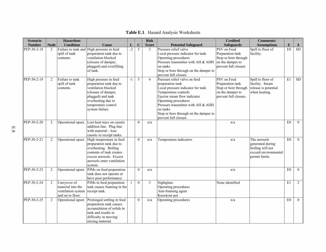
E.8
Table E.1. Hazard Analysis Worksheets
Scenario Number Node
Hazardous Condition Cause L C
Risk Score Potential Safeguard
Credited Safeguards
Comments/ Assumptions E $
PEP-30-2-18 2 Failure to tank and spill of tank contents.
High pressure in feed preparation tank due to ventilation blocked (closure of damper, plugged) and overfilling of tank.
-2 5 3 Pressure relief valve Local pressure indicator for tank Operating procedures Pressure transmitter with AH & AHH on tanks Stop or bore through on the damper to prevent full closure
PSV on Feed Preparation tank Stop or bore through on the damper to prevent full closure
Spill to floor of facility.
E0 SD
PEP-30-2-19 2 Failure to tank spill of tank contents.
High pressure in feed preparation tank due to ventilation blocked (closure of damper, plugged) and tank overheating due to temperature control system failure.
-1 5 4 Pressure relief valve on feed preparation tank Local pressure indicator for tank Temperature controls Ejector steam flow indicator Operating procedures Pressure transmitter with AH & AHH on tanks Stop or bore through on the damper to prevent full closure
PSV on Feed Preparation tank Stop or bore through on the damper to prevent full closure.
Spill to floor of facility. Steam release is potential when heating.
E1 SD
PEP-30-2-20 2 Operational upset. Lost heat trace on caustic addition line. Plug line with material—lose caustic to receipt tanks.
0 n/a n/a E0 0
PEP-30-2-21 2 Operational upset. High temperature in feed preparation tank due to overheating. Boiling contents of tank creates excess aerosols. Excess aerosols enter ventilation system.
0 n/a Temperature indicators n/a The aerosols generated during boiling will not exceed environmental permit limits.
E0 0
PEP-30-2-23 2 Operational upset. PJMs on feed preparation tank does not operate or have poor performance.
0 n/a n/a E0 0
PEP-30-2-24 2 Carryover of material into the ventilation system and on to floor.
PJMs in feed preparation tank causes foaming in the receipt tank.
1 0 3 Sightglass Operating procedures Anti-foaming agent Knockout pot
None identified E1 2
PEP-30-2-25 2 Operational upset. Prolonged settling in feed preparation tank causes accumulation of solids in tank and results in difficulty in moving/ mixing material.
0 n/a Operating procedures n/a E0 0

E.9
Table E.1. Hazard Analysis Worksheets
Scenario Number Node
Hazardous Condition Cause L C
Risk Score Potential Safeguard
Credited Safeguards
Comments/ Assumptions E $
PEP-30-2-26 2 Incomplete/“out of spec” batch of material. Lost time for test.
Failure in heat exchanger causes leak of chilled water or steam into process line and causes dilution of simulant mixture.
-2 0 0 n/a E0 2
PEP-30-2-27 2 Contaminate/ damage the chilled water or steam supply system.
Failure in heat exchanger causes leak of process material into chilled water or steam supply. Simulant mixture plugs system.
-2 0 1 Condensate collection system and blowdown on steam system Periodic chemistry test on chilled water system TDS monitoring on steam supply Water chemistry maintenance
Operating procedures Contamination in the system would take significant time before damage would occur.
E0 3
PEP-30-2-28 2 Operational upset. High temperature in the heating heat exchanger. Lose flow of simulant with steam in heat exchanger. Dry out system depositing scale from heat exchanger to feed preparation tank. Plug system.
0 n/a Flushing capability for lines Temperature monitoring Operating procedures
n/a E0 0
PEP-30-2-29 2 Operational upset. Low temperatures in the cooling heat exchanger due to stopping flow in the process loop. Precipitate oxalate and other solids plugging exchanger.
0 n/a Flushing capability for lines Temperature monitoring Operating procedures
n/a E0 0
PEP-30-2-30 2 Damage the heat exchanger loop releasing heated process material.
Closing isolation valves to heat exchanger with continued heating causes over pressurization.
1 5 6 Operating procedures Pressure relief to the heat exchanger Pressure Safety Valve
Operating proceduresPSV on heat exchanger
Relief valve added at the 90% design.
E0 SD
PEP-30-2-31 2 Large release of steam to the facility.
Catastrophic failure of the steam shell on the heat exchanger results in large release of steam.
-3 5 2 Design of steam shell to code Design of steam shell to code
E0 3
PEP-30-2-32 2 Collapse of steam shell.
Steam present in the shell; blocked off. Vacuum pulled collapsing shell upon cooling.
-1 0 2 Design of steam shell to code Operating procedures E0 3

E.10
Table E.1. Hazard Analysis Worksheets
Scenario Number Node
Hazardous Condition Cause L C
Risk Score Potential Safeguard
Credited Safeguards
Comments/ Assumptions E $
PEP-30-2-33 2 Small release of steam to the facility.
Structural failure of the steam shell of exchanger. Small leak of steam.
-1 2 1 None identified E0 1
PEP-90-2-01 2 Spill of simulant, sodium hydroxide, material, or inhibited water from other tanks, to the facility.
Flush valves are open during transfer, spilling material to the facility.
0 4 4 Facility secondary containment Operating procedures
PPE Facility secondary containment Operating proceduresFeed Preparation tank level detection
Added at 90% E0 1
PEP-90-2-02 2 Operational upset. Control valve is mis-aligned during transfer, resulting in material remaining in the feed preparation tank.
0 n/a n/a Added at 90% E0
PEP-90-2-03 2 Spill of simulant, sodium hydroxide, material, or inhibited water from other tanks, to the facility.
Control valve is mis-aligned during recirculation, resulting in material traveling to ultrafiltration feed vessel (T02A). Overflow tank to facility.
-1 4 3 Facility secondary containment Operating procedures PPE Personnel training Ultrafiltration feed tank level detection (thermocouples, bubblers, and laser)
PPE Facility secondary containment Operating procedures
Added at 90% E0 SD
PEP-90-2-04 2a Personnel injury due to debris projectiles.
Feeding PJMs with 100 psi air, open vacuum valve, and overpressurize the vacuum system. Failure of vacuum system.
-1 5 4 PLC PJM Level Detector PJM Pressure Detector PJM Rack Air Supply Valve
PLC PJM Level DetectorPJM Pressure Detector PJM Rack Air Supply Valve Feed Preparation tank level detection
Added at 90% E0 SD
PEP-30-2-34 2b Incomplete/“out of spec” batch of material. Lost time for test.
Add too much water to the feed preparation tank (inhibited or condensate from the sparger).
1 0 3 Flow totalizer on inhibited water Feed preparation tank level detection (thermocouples, bubblers, and laser) Steam flowmeter
Operating proceduresFeed Preparation tank level detection
Changed ejector to sparger at 100%
E0 2
PEP-30-2-35 2b Operational upset. No flow to the sparger from plugged orifice or loss of steam supply. Not able to heat the feed preparation tank with the steam.
0 n/a n/a Changed ejector to sparger at 100%
E0 0

E.11
Table E.1. Hazard Analysis Worksheets
Scenario Number Node
Hazardous Condition Cause L C
Risk Score Potential Safeguard
Credited Safeguards
Comments/ Assumptions E $
PEP-30-2-36 2b Large steam leak outside of feed preparation tank.
Failure of the steam system upstream of the tank, resulting in large release of steam.
-3 5 2 Design of steam system Operating procedures
Design of steam system to code Operating procedures
Changed ejector to sparger at 100%
E0 SD
PEP-30-2-37 2b Small steam leak outside of feed preparation tank.
Failure of the steam system upstream of the tank, resulting in small release of steam.
0 2 2 Design of steam system Operating procedures
Design of steam system to code Operating procedures
Changed ejector to sparger at 100%
E0 SD
PEP-FN-2-01 2b Carryover of material to the ventilation system.
Failure of steam sparger in the tank. As tank material is disturbed, it entrains simulant/chemicals into steam volume. Carry material up into the ventilation system.
-3 0 -1 Design of the steam system Knock out pots
None identified E1 2
PEP-30-2-40 2a Operational upset. No/low flow through pulse jet mixers.
0 n/a n/a E0 0
PEP-30-2-41 2a Carryover of material to the ventilation system.
High flow through the PJMs results in overblow.
1 0 3 PLC PJM Level Detector PJM Pressure Detector PJM Rack Air Supply Valve
PLC PJM Level DetectorPJM Pressure Detector PJM Rack Air Supply Valve Feed Preparation tank level detection
Revised at 90% to reflect PJM overblow controls
E1 2
PEP-30-2-42 2a Operational upset. Pull vacuum too long on PJM. Pull simulant into vacuum system, damaging system.
0 n/a Design of barometric leg n/a E0 0
PEP-30-2-43 2a Carryover of material to the ventilation system.
High pressure on the vacuum side or high pressure on the air side results in overblow.
1 0 3 PLC PJM Level Detector PJM Pressure Detector PJM Rack Air Supply Valve
PLC PJM Level DetectorPJM Pressure Detector PJM Rack Air Supply Valve Feed Preparation tank level detection
Revised at 90% to reflect PJM overblow controls
E1 2
PEP-30-2-44 2a Operational upset. Vacuum results in boiling at the PJMs due to high temperature of material, resulting in vapors and
0 n/a Design feature in the vacuum system to handle condensables.
n/a E0 0

E.12
Table E.1. Hazard Analysis Worksheets
Scenario Number Node
Hazardous Condition Cause L C
Risk Score Potential Safeguard
Credited Safeguards
Comments/ Assumptions E $
condensate accumulating in vacuum system.
PEP-30-2-45 2a Operational upset. Lose structural integrity of the air supply to the PJMs. Blow air out into tank at 100 psi (24 cfm).
0 n/a n/a E0 0
PEP-30-3-01 3 Operational upset. No flow into the ultrafiltration feed tank due to closed isolation valve.
0 n/a n/a E0 0
PEP-30-3-02 3 Spill of simulant, sodium hydroxide, nitric acid/oxalic acid, material, or inhibited water from other tanks.
No flow into the tank due to leak in chemical addition or transfer piping (flanges, etc.).
0 4 4 Leak test at installation Facility secondary containment Operating procedures PPE Personnel training Ultrafiltration feed tank level detection (thermocouples, bubblers, and laser) Flow totalizers on major chemical additions Flow meter on transfer line
PPE Operating procedures Facility secondary containment Ultrafiltration feed tank level detection
Potential for caustic/acidic burn/eye damage. Leak is inside facility.
E0 1
PEP-30-3-03 3 Operational upset. Add acid to tank when simulant is present, causing tank to boil due to reaction. Release aerosols to ventilation system.
0 n/a n/a This is 2 Molar nitric acid. The aerosols generated during boil will not exceed environmental permit limits.
E0 0
PEP-30-3-04 3 Operational upset. No flow into the ultrafiltration feed tank due to pump failure or plugging of chemical addition or transfer piping (flanges, etc.).
0 n/a n/a E0 0
PEP-30-3-05 3 Operational upset. No flow out of ultrafiltration feed tank due to pump not operating.
0 n/a n/a E0 0
PEP-30-3-06 3 Operational upset. No flow out of ultrafiltration feed tank due to line plugging.
0 n/a n/a E0 0

E.13
Table E.1. Hazard Analysis Worksheets
Scenario Number Node
Hazardous Condition Cause L C
Risk Score Potential Safeguard
Credited Safeguards
Comments/ Assumptions E $
PEP-30-3-07 3 Spill of ultrafiltration tank contents (simulant, sodium hydroxide, nitric acid/oxalic acid, material, or inhibited water from other tanks).
Structural integrity of ultrafiltration feed tank degraded, resulting in leak.
-3 4 1 Design of tanks to code Design of ultrafiltration feed tank to code
Spill to floor of facility. Potential for caustic burn/eye damage pH~14. Likelihood assigned based on tank to code.304 SST is listed as having excellent chemical compatibility to nitric acid and good compatibility with NaOH and oxalic acid.
E0 3
PEP-30-3-08 3 Spill of ultrafiltration tank contents (simulant, sodium hydroxide, nitric acid/oxalic acid, material, or inhibited water from other tanks).
No flow out of the ultrafiltration feed tank due to leak in transfer piping/pumps.
0 4 4 Leak test at installation Facility secondary containment Operating procedures PPE Personnel training Ultrafiltration feed tank level detection (thermocouple, bubblers and laser) Flow meter on transfer line
PPE Operating procedures Facility secondary containment Ultrafiltration feed tank level detection
Spill to floor of facility. Potential for caustic/acidic burn/eye damage. Likelihood assigned based on tank to code.
E0 SD
PEP-30-3-09 3 Carryover of material to the ventilation system.
Lower-than-intended ultrafiltration feed tank volume. Tank level below level of the PJMs results in overblow. Material in the vent line.
1 0 3 PLC PJM Level Detector PJM Pressure Detector PJM Rack Air Supply Valve
PLC PJM Level DetectorPJM Pressure Detector PJM Rack Air Supply Valve Ultrafiltration feed tank level detection
Revised at 90% to reflect PJM overblow controls.
E1 2
PEP-30-3-10 3 No issue identified.
Filling tank too fast. 0 n/a n/a Ventilation system is designed to accommodate for any excess aerosols generated during this event.
E0 0

E.14
Table E.1. Hazard Analysis Worksheets
Scenario Number Node
Hazardous Condition Cause L C
Risk Score Potential Safeguard
Credited Safeguards
Comments/ Assumptions E $
PEP-30-3-11 3 Operational upset. Too much material added, resulting in boiling in ultrafiltration feed tank. Excess aerosols enter ventilation system.
0 n/a n/a Aerosols generated during boiling will not exceed environment permit limits.
E0 0
PEP-30-3-12 3 Spill of ultrafiltration tank contents (simulant, sodium hydroxide, nitric acid/oxalic acid, material, or inhibited water from other tanks).
Too much material added to the ultrafiltration tank resulting in overflow of tank to facility floor.
0 4 4 Facility secondary containment Operating procedures PPE Personnel training Ultrafiltration feed tank level detection (thermocouples, bubblers, and laser) Flow totalizers on major chemical additions Flow meter on transfer line
PPE Operating procedures Facility secondary containment Ultrafiltration feed tank level detection and alarms
Spill to floor of facility. Potential for caustic/acidic burn/eye damage.
E0 SD
PEP-30-3-13 3 Incomplete/“out of spec” batch of material. Lost time for test.
Too much material added to the tank. High level in tank.
1 0 3 Operating procedures Ultrafiltration feed tank level detection (thermocouples, bubblers, and laser) Flow totalizers on major chemical additions Flow meter on transfer line
Ultrafiltration feed tank level detection and alarms
E0 2
PEP-30-3-14 3 Operational upset. Too much caustic added causes formation of oxalates in tank.
0 n/a n/a E0 0
PEP-90-3-01 3 Spill of ultrafiltration tank contents (simulant, sodium hydroxide, nitric acid/oxalic acid, material, or inhibited water from other tanks).
Ultafiltration pump flush valves left open during pump operation. Pump ultrafiltration tank contents into drain pan, overflowing pan into facility.
0 4 4 Facility secondary containment Operating procedures PPE Personnel training Ultrafiltration feed tank level detection (thermocouples, bubblers, and laser)
PPE Facility secondary containment Operating proceduresUltrafiltration feed tank level detection
Added at 90% E0 SD
PEP-30-3-15 3 Incomplete/“out of spec” batch of material. Lost time for test.
Too little caustic added, resulting in contents too low in caustic through ultrafiltration system.
1 0 3 Operating procedures Ultrafiltration feed tank level detection (thermocouples, bubblers, and laser) Flow totalizers on major chemical additions
Operating procedures E0 2

E.15
Table E.1. Hazard Analysis Worksheets
Scenario Number Node
Hazardous Condition Cause L C
Risk Score Potential Safeguard
Credited Safeguards
Comments/ Assumptions E $
PEP-30-3-16 3 Incomplete/“out of spec” batch of material. Lost time for test.
Delivery of “out of spec” caustic results in wrong batch specs.
1 0 3 Require certification from vendor with each batch.
Operating procedures E0 2
PEP-30-3-17 3 Operational upset. Low pressure in ultrafiltration feed tank due to plugging of ventilation (closure of damper, plugged) during transfer out.
0 n/a Design of tanks to 7.5 psid external Stop or bore through on the damper to prevent full closure.
n/a System is designed such that the pumps cannot draw enough suction to damage tank.
E0 0
PEP-30-3-19 3 Failure of ultrafiltration tank and spill of tank contents (simulant, sodium hydroxide, nitric acid/oxalic acid, material, or inhibited water from other tanks).
High pressure in ultrafiltration feed tank due to ventilation blocked (closure of damper, plugged) and overfilling of tank.
-2 5 3 Pressure relief valve Local pressure indicator for tank Operating procedures Pressure transmitter Stop or bore through on the damper to prevent full closure.
PSV on Ultrafiltration Feed tank Stop or bore through on the damper to prevent full closure
Spill to floor of facility.
E0 SD
PEP-30-3-20 3 Failure of ultrafiltration tank and spill of tank contents (simulant, sodium hydroxide, nitric acid/oxalic acid, material, or inhibited water from other tanks).
High pressure in ultrafiltration feed tank due to ventilation blocked (closure of damper, plugged) and overheat the tank due to temperature control system failure.
-1 5 4 Pressure relief valve Local pressure indicator for tank Temperature controls Ejector steam flow indicator Operating procedures Pressure transmitter Stop or bore through on the damper to prevent full closure.
PSV on Ultrafiltration Feed tank Stop or bore through on the damper to prevent full closure.
Spill to floor of facility. Steam release is potential when heating.
E0 SD
PEP-30-3-21 3 Operational upset. Lost heat trace on caustic addition line. Plug line with material—lose caustic to receipt tanks.
0 n/a n/a E0 0
PEP-30-3-22 3 Operational upset. High temperature in ultrafiltration feed tank due to overheating. Boiling contents of tank, creates excess aerosols. Excess aerosols enter ventilation system.
0 n/a Temperature indicators n/a The aerosols generated during boiling will not exceed environmental permit limits.
E0 0
PEP-30-3-24 3 Operational upset. PJM does not operate or has poor performance.
0 n/a n/a E0 0

E.16
Table E.1. Hazard Analysis Worksheets
Scenario Number Node
Hazardous Condition Cause L C
Risk Score Potential Safeguard
Credited Safeguards
Comments/ Assumptions E $
PEP-30-3-25 3 Carryover of material into the ventilation system and on to floor.
PJM causes foaming in the receipt tank.
1 0 3 Operating procedures Anti-foaming agent Knockout pot
None identified E1 2
PEP-30-3-26 3 Operational upset. Prolonged settling in tank causes accumulation of solids in tank and results in difficulty moving/ mixing of material.
0 n/a Operating procedures n/a E0 0
PEP-30-3-27 3 Incomplete/“out of spec” batch of material. Lost time for test.
Failure in heat exchanger causes leak of chilled water or steam into process line and causes dilution of simulant mixture.
-2 0 0 None identified E0 2
PEP-30-3-28 3b Incomplete/“out of spec” batch of material. Lost time for test.
Add too much water to ultrafiltration feed tank (inhibited or condensate from the sparger).
1 0 3 Flow totalizer on inhibited water Ultrafiltration feed tank level detection (thermocouples, bubblers, and laser) Steam Flowmeter
Operating procedures Changed ejector to sparger at 100%
E0 2
PEP-30-3-29 3b Operational upset. No flow to the spargers from plugged orifice or loss of steam supply. Not able to heat the tank with steam.
0 n/a n/a Changed ejector to sparger at 100%
E0 0
PEP-30-3-30 3b Large steam leak outside of tank.
Failure of the steam system upstream of the tank, resulting in large release of steam.
-3 5 2 Design of steam system Operating procedures
Design of steam system to code Operating procedures
Changed ejector to sparger at 100%
E0 SD
PEP-30-3-31 3b Small steam leak outside of tank.
Failure of the steam system upstream of the tank, resulting in small release of steam.
0 2 2 Design of steam system Operating procedures
Design of steam system to code Operating procedures
Changed ejector to sparger at 100%
E0 SD
PEP-FN-3-01 3b Carryover of material to the ventilation system.
Failure of steam sparger in the tank. As tank material is disturbed in entrains simulant/ chemicals into steam volume. Carry material up into the ventilation system.
-3 0 -3 Design of the steam system Knock out pots
None identified E1 2

E.17
Table E.1. Hazard Analysis Worksheets
Scenario Number Node
Hazardous Condition Cause L C
Risk Score Potential Safeguard
Credited Safeguards
Comments/ Assumptions E $
PEP-30-3-34 3a Operational upset. No/low flow through pulse jet mixers.
0 n/a n/a E0 0
PEP-30-3-35 3a Carryover of material to the ventilation system.
High flow through the PJMs results in overblow.
1 0 3 PLC PJM Level Detector PJM Pressure Detector PJM Rack Air Supply Valve
PLC PJM Level DetectorPJM Pressure Detector PJM Rack Air Supply Valve Ultrafiltration feed tank level detection
Revised at 90% to reflect PJM overblow controls
E1 2
PEP-30-3-36 3a Operational upset. Pull vacuum too long on PJM. Pull simulant into vacuum system damaging system.
0 n/a Design of barometric leg n/a E0 0
PEP-30-3-37 3a Carryover of material to the ventilation system.
High pressure on the vacuum side or high pressure on the air side results in overblow.
1 0 3 PLC PJM Level Detector PJM Pressure Detector PJM Rack Air Supply Valve
PLC PJM Level DetectorPJM Pressure Detector PJM Rack Air Supply Valve Ultrafiltration feed tank level detection
Revised at 90% to reflect PJM overblow controls
E1 2
PEP-30-3-38 3a Operational upset. Vacuum results in boiling due to high temperature of material, resulting in vapors and condensate accumulating in vacuum system.
0 n/a Design feature in the vacuum system to handle condensables.
n/a E0 0
PEP-30-3-39 3a Operational upset. Lose structural integrity of the air supply to the PJMs. Blow air out into tank at 100 psi (24 cfm).
0 n/a n/a E0 0
PEP-30-3-40 3 Internal vessel and jacket is damaged, releasing hot water.
Block flow (close valves) to the chilled water jacket resulting in over pressurization of jacket.
1 3 5 Operating procedures Flow meter on chilled water system Pressure relief valve
Operating proceduresPSV on chilled water jacket
E0 4
PEP-30-3-41 3 Spill ultrafiltration tank contents to the floor (simulant, sodium hydroxide, nitric acid/oxalic acid,
Failure of the chilled water system and chilled water leaking into the ultrafiltration tank, resulting in overflowing the tank.
-2 4 2 Facility secondary containment Operating procedures PPE Personnel training Ultrafiltration feed tank level detection (thermocouples, bubblers,
PPE Facility secondary containment Ultrafiltration feed tank level detection and alarms
Spill to floor of facility. Potential for caustic/acid burn/eye damage.
E0 SD

E.18
Table E.1. Hazard Analysis Worksheets
Scenario Number Node
Hazardous Condition Cause L C
Risk Score Potential Safeguard
Credited Safeguards
Comments/ Assumptions E $
material, or inhibited water from other tanks).
and laser) Flow meter on chilled water
PEP-30-3-42 3 Operational upset. No air flow in the sparer results in plugging of sparger system.
0 n/a Flow totalizer on sparger Local flowmeter
n/a E0 0
PEP-30-3-43 3 Carryover of material into the ventilation system and on to floor.
Flow or air through sparger to high. Results in foaming and aerosol generation.
1 0 3 Operating procedures Anti-foaming agent Knockout pot Flow totalizer on sparger
None identified E1 2
PEP-30-3-44 3 Carryover of material into the ventilation system and on to floor.
Regulator failure results in high pressure flow through sparger.
1 0 3 Operating procedures Anti-foaming agent Knockout pot Flow totalizer on sparger Pressure indicator on the header
Operating procedures E1 2
PEP-30-3-45 3 Operational upset. Lose structural integrity of the air supply to the sparger. Blow air out into tank at 15 psi (4 cfm).
0 n/a n/a E0 0
PEP-30-4-01 4b Contaminate/ damage the chilled water or steam supply system.
Failure in heat exchanger causes leak of process material into chilled water or steam supply. Simulant mixture plugs system.
-2 0 1 Condensate collection system and blowdown on steam system Periodic chemistry test on chilled water system Total Dissolved Solids (TDS) monitoring on steam supply Water chemistry maintenance
Operating procedures Contamination in the system would take significant time before damage would occur.
E0 3
PEP-30-4-02 4b Contaminate/ damage the chilled water or steam supply system.
Failure of heat exchanger causes leak of nitric acid into chilled water supply or steam supply.
-2 0 1 Condensate collection system and blowdown on steam system Periodic chemistry test on chilled water system TDS monitoring on steam supply Water chemistry maintenance
Operating procedures Contamination in the system would take significant time before damage would occur.
E0 3
PEP-30-4-03 4b Operational upset. High temperature in the heating heat exchanger. Lose flow of simulant with steam in heat exchanger. Dry out system, depositing scale, plugging ultrafilters.
0 n/a Flushing capability for system Temperature monitoring Pulse pots designed to clear ultrafiltersOperating procedures
n/a E0 0

E.19
Table E.1. Hazard Analysis Worksheets
Scenario Number Node
Hazardous Condition Cause L C
Risk Score Potential Safeguard
Credited Safeguards
Comments/ Assumptions E $
PEP-30-4-04 4b Operational upset. Low temperatures in the cooling heat exchanger due to stopping flow in the process loop. Precipitate oxalate and other solids, plugging ultrafilters.
0 n/a Flushing capability for system Temperature monitoring Pulse pots designed to clear ultrafiltersOperating procedures
n/a E0 0
PEP-30-4-05 4b Damage the heat exchanger loop, releasing heated process material.
Close isolation valves to heat exchanger with continued heating causes over pressurization.
1 5 6 Operating procedures Pressure relief to heat exchanger Pressure relief valve
Operating proceduresPSV on heat exchanger
Relief valve added at the 90% design.
E0 SD
PEP-30-4-06 4b Large release of steam to the facility.
Catastrophic failure of the steam shell on the heat exchanger results in large release of steam.
-3 5 2 Design of steam shell to code Design of steam shell to code
E0 3
PEP-30-4-07 4b Collapse of steam shell.
Steam present in the shell, blocked off. Vacuum pulled collapsing shell on cooling.
-1 0 2 Vacuum breakers on jacket Operating procedures
Operating procedures E0 3
PEP-30-4-08 4b Small release of steam to the facility.
Structural failure of the steam shell of exchanger. Small leak to steam.
-1 2 1 Design of steam shell to code
E0 1
PEP-30-4-09 4 Spill of simulant, sodium hydroxide, sodium permanganate, nitric acid, or inhibited water.
No flow in the ultrafiltration loop due to leak in chemical addition or transfer piping (flanges,etc.).
0 4 4 Leak test at installation Facility secondary containment Operating procedures PPE Personnel training Ultrafiltration feed tank level detection (thermocouples, bubblers, and laser) Flow totalizers on major chemical additions Flow meter on transfer line
PPE Facility secondary containment Operating procedures
Potential for caustic/acidic burn/eye damage. Leak is inside facility.
E0 SD
PEP-30-4-10 4 Operational upset. Low pressure in system, reducing filtration capability of system.
0 n/a n/a E0 0
PEP-30-4-11 4 Operational upset. Backpulse filters when pumps shut down. Pushing ~400 psi air back through system to UFP-VSL-T02A. Air generated aerosols that are
0 n/a n/a Aerosols generated will not exceed environment permit limits. The pressure available in air system changes
E0 0

E.20
Table E.1. Hazard Analysis Worksheets
Scenario Number Node
Hazardous Condition Cause L C
Risk Score Potential Safeguard
Credited Safeguards
Comments/ Assumptions E $
released through ventilation.
from 300 psi to 500 psi (controlled @ ~400psi) at 90% design.
PEP-30-4-12 4 Operational upset. Low flow through ultra filters plugs up filters, reducing filtration capabilities.
0 n/a n/a E0 0
PEP-30-4-13 4 Loss of filtration capability and material in UFP-VSL-62A/B.
Failure in the ultrafilter tube bundle results in material backing up into the pulse pots and eventually to UFP-VSL-62A/B.
0 0 1 Spare tubes on hand None identified E0 1
PEP-30-4-14 4 Operational upset. Temperature lowered below leaching temperature. Slows down process.
0 n/a n/a E0 0
PEP-30-4-15 4 Operational upset. High temperature in system results in loss of suction and potential pump damage.
0 n/a n/a E0 0
PEP-30-4-17 4a Operational upset. No flow through one pulse pot due to plugging of line or valve closure. Eliminates capability to pulse filter.
0 n/a n/a E0 0
PEP-30-4-18 4a Operational upset. Failure to shut off ~400 psi air and do not shut off valve at pulse pot. Continue air flow across filters, dry out utrafilters. Potential to damage filter.
0 n/a n/a The pressure available in air system changes from 300 psi to 500 psi (controlled @ ~400psi) at 90% design. Need to verify filter assembly design pressure to understand this event.
E0 0
PEP-30-4-19 4a Leak of permeate and pressurized air into facility.
Catastrophic failure of pulse pot structure. Event happens when pulsing.
-3 5 2 Design of pulse pot to code Pressure relief
Design of pulse pot to code PSV on pulse pot
E0 SD

E.21
Table E.1. Hazard Analysis Worksheets
Scenario Number Node
Hazardous Condition Cause L C
Risk Score Potential Safeguard
Credited Safeguards
Comments/ Assumptions E $
PEP-30-4-20 4a Small pressurized leak of permeate to facility.
Failure of pulse pot structure, resulting in small leak.
0 3 3 Design of pulse pot to code Pressure relief When system is pressurized, the time frame is short
Design of pulse pot to code
E0 SD
PEP-30-4-21 4a Release of reaction aerosols out of nitric acid tank to facility.
Backflow of permeate back into the nitric acid addition system. Reaction in nitric acid tank releasing aerosols out of vent.
0 3 3 Check valve on nitric system Automatically controlled addition valve Automated addition sequence Relief valve on pulse pot
Operating procedures E0 SD
PEP-90-4-01 4a Small leak of simulant to facility.
No/low water in or no flow from seal pots causes loss of pump sealing. Simulant leaks out of seal into the facility.
0 0 0 None identified Added at 90% E0 0
PEP-90-4-02 4a Small leak of simulant to facility.
High temperature in seal pots causes damage to pump seals. Simulant leaks out of seal into the facility.
0 0 0 None identified Added at 90% E0 0
PEP-90-4-03 4a Operational upset. Overfill the seal pots when adding water (ventilation system off and valve open). Spill water to facility floor.
0 n/a n/a Added at 90% E0 0
PEP-90-4-04 4a Small leak of simulant to facility.
Low/no pressure from air supply to seal pot system causes loss of pump sealing. Simulant leaks out of seal into the facility.
0 0 0 None identified Added at 90% E0 0
PEP-90-4-05 4a Spill of simulant, sodium hydroxide, sodium permanganate, nitric acid, or inhibited water.
High pressure air causes failure of filter assembly, releasing material to the facility.
-3 4 1 TBD Design of filter assembly
Pumps on the tube side can increase pressure across filters
E0 SD
PEP-30-5-01 5 Operational upset. No flow into the tank due to closed isolation valve or pump not operating.
0 n/a n/a E0 0

E.22
Table E.1. Hazard Analysis Worksheets
Scenario Number Node
Hazardous Condition Cause L C
Risk Score Potential Safeguard
Credited Safeguards
Comments/ Assumptions E $
PEP-30-5-02 5 Spill of concentrated slurry, inhibited water to the facility floor.
No flow into the tank due to leak at the connection to the flex hose connection to the portable pump.
1 4 5 Facility secondary containment Operating procedures PPE Personnel training Tank level detection (bubbler) Flow totalizer on inhibited water
PPE Facility secondary containment Operating proceduresSlurry Concentrate tank level detection
Potential for caustic burn/eye damage pH~12.
E1 1
PEP-30-5-03 5 Spill of concentrated slurry, inhibited water.
No flow into the tank due to leak in transfer piping (flanges, etc.).
0 4 4 Leak test at installation Facility secondary containment Operating procedures PPE Personnel training Tank level detection (bubbler) Flow totalizer on inhibited water
PPE Facility secondary containment Operating proceduresSlurry Concentrate tank level detection
Potential for caustic burn/eye damage pH~12. Leak is inside facility.
E0 1
PEP-30-5-04 5 Operational upset. No flow out of tank due to portable pump not operating.
0 n/a n/a E0 0
PEP-30-5-05 5 Operational upset. No flow out of tank due to line plugging.
0 n/a n/a E0 0
PEP-30-5-06 5 Spill of concentrated slurry, inhibited water.
Structural integrity of tank degraded, resulting in leak.
-3 4 1 Design of tanks to code Design of Slurry Concentrate tank to code
Spill to floor of facility. Potential for caustic burn/eye damage pH~14. Likelihood assigned based on tank to code.304 SST is listed as having excellent chemical compatibility to nitric acid, and good compatibility with NaOH, and oxalic acid.
E0 SD
PEP-30-5-07 5 Spill of concentrated slurry, inhibited water.
No flow to the receiving end due to leak in transfer piping/pumps.
0 4 4 Leak test at installation Facility secondary containment Operating procedures PPE Personnel training Tank level detection (bubbler)
PPE Facility secondary containment Operating proceduresSlurry Concentrate tank level detection
Spill to floor of facility. Potential for caustic burn/eye damage pH~12.
E0 SD

E.23
Table E.1. Hazard Analysis Worksheets
Scenario Number Node
Hazardous Condition Cause L C
Risk Score Potential Safeguard
Credited Safeguards
Comments/ Assumptions E $
PEP-30-5-08 5 Spill of concentrated slurry, inhibited water.
No flow to receiving end due to leak at the connection to the simulant addition flex hose.
1 4 5 Facility secondary containment Operating procedures PPE Personnel training Tank level detection (bubbler)
PPE Facility secondary containment Operating proceduresSlurry Concentrate tank level detection
Spill to floor of facility. Potential for caustic burn/eye damage pH~12.
E0 1
PEP-30-5-09 5 No issue identified.
Filling tank too fast. 0 n/a n/a Ventilation system is designed to accommodate for any excess aerosols generated during this event.
E0 0
PEP-30-5-10 5 Overflow of tank contents to ventilation system, damaging fans, exchanger, and blower. Boil off of liquids forming solids in vent lines.
Too much material added to the tank, resulting overflow of tank to the ventilation system.
1 0 3 Facility secondary containment Operational procedures Tank level detection (bubbler) High level alarm Flow totalizer on inhibited water system Interlock to shutdown inhibited water
Slurry concentrate tank level detection and alarm
E2 2
PEP-30-5-11 5 Spill of concentrated slurry, inhibited water on to facility floor.
Too much material added to the tank with valves open, resulting in spill out of transfer line onto floor.
0 4 4 Facility secondary containment Operational procedures Tank level detection (bubbler) High level alarm Flow totalizer on inhibited water system Interlock to shutdown inhibited water
PPE Facility secondary containment Operating proceduresSlurry concentrate tank level detection and alarm
E0 SD
PEP-30-5-12 5 Operational upset. Too much material added to the tank with valves open, resulting in backflow to UFB-VSL-62A.
0 n/a n/a E0 0
PEP-30-5-13 5 Spill of concentrated slurry, inhibited water, nitric acid, or simulant on to facility floor.
No flow to tank due to portable pump discharge line open, transferring material directly out open valve.
1 4 5 Facility secondary containment Operating procedures Level detection on intended source tank Level detection on intended receiving tank
PPE Facility secondary containment Operating proceduresSlurry Concentrate tank level detection
E0 SD
PEP-30-5-14 5 Operational upset. Too much material added to the tank. High level in tank.
1 0 3 Tank Level detection (bubbler) Flow totalizer Operating procedures
Slurry Concentrate tank level detection and alarm
E0 2

E.24
Table E.1. Hazard Analysis Worksheets
Scenario Number Node
Hazardous Condition Cause L C
Risk Score Potential Safeguard
Credited Safeguards
Comments/ Assumptions E $
PEP-30-5-15 5 Overflow of receipt tank contents to ventilation system damaging fans, exchanger, and blower. Boil off of liquids forming solids in vent lines.
Backflow of material from UFP-VSL-T62A to tank T27 caused by valves open and over fill T62A.
0 0 2 Level detection in T27 and alarms Operating procedures
Operating procedures E2 2
PEP-30-5-16 5 Operational upset. Low pressure in receipt tank due to plugging of ventilation (closure of damper) during transfer out.
0 n/a Design of tanks to 7.5 psid external Stop or bore through on the damper to prevent full closure.
n/a System is designed such that the pumps cannot draw enough to damage tank.
E0 0
PEP-30-5-18 5 Failure of tank and spill tank contents.
High pressure in receipt tank due to ventilation blocked (closure of damper) and overfilling of tank.
1 5 6 Pressure relief valve Local pressure indicator for tank Operating procedures Pressure Transmitter Stops or bore through on the damper to prevent full closure.
PSV on Slurry Concentrate tank Stop or bore through on the damper to prevent full closure.
Spill to floor of facility.
E0 SD
PEP-30-5-19 5 Operational upset. Agitator in receipt tank does not operate or poor mixing due to VFD too slow. Solids settle out.
0 n/a n/a E0 0
PEP-30-5-20 5 Operational upset. Prolonged settling in tank causes accumulation of solids in tank and results in difficulty moving/ mixing of material.
0 n/a Operating procedures n/a E0 0
PEP-30-6-01 6a Operational upset. High temperature in the tank prevents emptying the tank. Affects operation time.
0 n/a n/a E0 0
PEP-30-6-02 6a Operational upset. No flow into the tank due to closed isolation valve or pump not operating.
0 n/a n/a E0 0

E.25
Table E.1. Hazard Analysis Worksheets
Scenario Number Node
Hazardous Condition Cause L C
Risk Score Potential Safeguard
Credited Safeguards
Comments/ Assumptions E $
PEP-30-6-03 6a Spill of permeate, concentrated slurry, simulant, sodium hydroxide, sodium permanganate, nitric acid, or inhibited water to the facility floor.
No flow into the tank due to leak at the connection to the flex hose connection to the portable pump.
1 4 5 Facility secondary containment Operating procedures PPE Personnel training Evaporator tank level detection (bubbler) Flow totalizer on inhibited water Flow totalizer on sodium hydroxide
PPE Facility secondary containment Operating proceduresPermeate receipt tank level detection
Potential for caustic/acidic burn/eye damage.
E0 1
PEP-30-6-04 6a Spill of permeate, concentrated slurry, simulant, sodium hydroxide, sodium permanganate, nitric acid, or inhibited water to the facility floor.
No flow into the tank due to leak in transfer piping (flanges, etc.).
0 4 4 Leak test at installation Facility secondary containment Operating procedures PPE Personnel training Evaporator tank level detection (bubbler) Flow totalizer on inhibited water Flow totalizer on sodium hydroxide
PPE Facility secondary containment Operating proceduresPermeate receipt tank level detection
Potential for caustic burn/eye damage pH~12. Leak is inside facility.
E0 1
PEP-30-6-05 6a Operational upset. No flow out of tank due to portable pump not operating.
0 n/a n/a E0 0
PEP-30-6-06 6a Operational upset. No flow out of tank due to line plugging.
0 n/a n/a E0 0
PEP-30-6-07 6a Spill of permeate, concentrated slurry, simulant, sodium hydroxide, sodium permanganate, nitric acid, or inhibited water to the facility floor.
Structural integrity of tank degraded resulting in leak.
-3 4 1 Design of tanks to code Design of permeate receipt tanks to code
Spill to floor of facility. Potential for caustic burn/eye damage pH~14. Likelihood assigned based on tank to code.304 SST is listed as having excellent chemical compatibility to nitric acid, and good compatibility with NaOH, and oxalic acid.
E0 SD
PEP-30-6-08 6a Spill of permeate, concentrated slurry, simulant, sodium hydroxide,
No flow to the receiving tank due to leak in transfer piping/pumps.
0 4 4 Leak test at installation Facility secondary containment Operating procedures PPE
PPE Facility secondary containment Operating procedures
Spill to floor of facility. Potential for caustic
E0 SD

E.26
Table E.1. Hazard Analysis Worksheets
Scenario Number Node
Hazardous Condition Cause L C
Risk Score Potential Safeguard
Credited Safeguards
Comments/ Assumptions E $
sodium permanganate, nitric acid, or inhibited water to the facility floor.
Personnel training Evaporator tank and receiving tank level detection (bubbler)
Permeate receipt tank level detection
burn/eye damage pH~12.
PEP-30-6-09 6a Spill of permeate, concentrated slurry, simulant, sodium hydroxide, sodium permanganate, nitric acid, or inhibited water to the facility floor.
No flow to receiving end due to leak at the connection to the simulant addition flex hose.
1 4 5 Facility secondary containment Operating procedures PPE Personnel training Evaporator tank level detection (bubbler)
PPE Facility secondary containment Operating proceduresPermeate receipt tank level detection
Spill to floor of facility. Potential for caustic burn/eye damage pH~12.
E0 1
PEP-30-6-10 6a No issue identified.
Filling tank too fast. 0 n/a n/a Ventilation system is designed to accommodate for any excess aerosols generated during this event.
E0 0
PEP-30-6-11 6a Overflow of tank contents to ventilation system, damaging fans, exchanger and blower. Boiling off liquids forming solids in vent lines.
Too much material added to the tank resulting overflow of tank to the ventilation system.
1 0 3 Facility secondary containment Operating procedures Tank level detection (bubbler) High level alarm Flow totalizer on inhibited water system Interlock to shutdown inhibited water
Permeate receipt tank level detection and alarm
E2 2
PEP-30-6-12 6a Spill of permeate, concentrated slurry, simulant, sodium hydroxide, sodium permanganate, nitric acid, or inhibited water to the facility floor.
Too much material added to the tank with valves open, resulting in spill out of transfer line onto floor.
0 4 4 Facility secondary containment Operating procedures Evaporator tank level detection (bubbler) High level alarm Flow totalizer on inhibited water system Interlock to shutdown inhibited water
PPE Facility secondary containment Operating proceduresPermeate receipt tank level detection and alarm
E0 SD

E.27
Table E.1. Hazard Analysis Worksheets
Scenario Number Node
Hazardous Condition Cause L C
Risk Score Potential Safeguard
Credited Safeguards
Comments/ Assumptions E $
PEP-30-6-13 6a Operational upset. Too much material added to the tank with valves open, resulting in backflow to other process tanks.
0 n/a n/a E0 0
PEP-30-6-14 6a Spill of permeate, concentrated slurry, simulant, sodium hydroxide, sodium permanganate, nitric acid, or inhibited water to the facility floor from the chemical addition tank.
Too much material added to the tank with valves open, resulting in backflow to chemical addition tank (sodium hydroxide, inhibited water).
-1 4 3 Facility secondary containment Operating procedures Evaporator tank level detection (bubbler) High level alarm Automatic block valve on sodium hydroxide line Check valves
Operating procedures E0 SD
PEP-30-6-15 6a Spill of permeate, concentrated slurry, simulant, sodium hydroxide, sodium permanganate, nitric acid, or inhibited water to the facility floor.
No flow to receiving tank due to portable pump discharge line open transferring material directly out open valve.
1 4 5 Facility secondary containment Operating procedures Level detection on intended source tank Level detection on intended receiving tank
PPE Facility secondary containment Operating proceduresPermeate receipt tank level detection
E0 SD
PEP-30-6-16 6a Operational upset. Too much material added to the tank. High level in tank.
0 n/a Tank Level detection (bubbler) Flow totalizer Operating procedures
n/a E0 SD
PEP-30-6-17 6a Overflow of receipt tank contents to ventilation system, damaging fans, exchanger and blower. Boiling off liquids and forming solids in vent lines.
Misroute of material from source vessel to tank T62A caused by valve misalignment (intended to transfer to tank other than T62A). Overflow T62A.
1 0 3 Level detection in T62A and alarms Operating procedures
Operating procedures E2 2

E.28
Table E.1. Hazard Analysis Worksheets
Scenario Number Node
Hazardous Condition Cause L C
Risk Score Potential Safeguard
Credited Safeguards
Comments/ Assumptions E $
PEP-30-6-18 6a Operational upset. Low pressure in receipt tank due to plugging of ventilation (closure of damper) during transfer out.
0 n/a Design of tanks to 7.5 psid external Stop or bore through on the damper to prevent full closure.
n/a E0 0
PEP-30-6-20 6a Spill of permeate, concentrated slurry, simulant, sodium hydroxide, sodium permanganate, nitric acid, or inhibited water to the facility floor.
High pressure in receipt tank due to ventilation blocked (closure of damper) and overfilling of tank.
1 5 6 Pressure relief valve Local pressure indicator for evaporator tank High level alarm in evaporator tank Operating procedures Pressure Transmitter Stops or bore through on the damper to prevent full closure.
PSV on permeate receipt tank Stop or bore through on the damper to prevent full closure.
Spill to floor of facility.
E0 SD
PEP-30-6-21 6a Operational upset. Agitator in receipt tank does not operate or poor mixing due to VFD too slow. Solids settle out.
0 n/a n/a E0 0
PEP-30-6-22 6a Operational upset. Prolonged settling in tank causes accumulation of solids in tank and results in difficulty moving/ mixing of material.
0 n/a Operating procedures n/a E0 0
PEP-30-6-23 6a Damage equipment and holdup of operation.
Evaporate material to higher concentration than wanted. Let tank cool; material solidifies in tank. Potential to damage agitator.
1 0 5 Evaporator tank level detection (bubbler) Sampling Operating procedures
Operating proceduresPermeate evaporation tank level detection Permeate evaporation tank temperature indication
E0 4
PEP-30-6-24 6a Failure of tank releasing permeate, concentrated slurry, simulant, sodium hydroxide, sodium permanganate, nitric acid, or inhibited water to the facility.
Over heat evaporator tank with ventilation blocked (closure of damper, plugging) causes over pressurization and damage to tank.
1 5 6 Pressure relief valve Local pressure indicator for tank Temperature indication High-high temperature shutdown Operating procedures Pressure Transmitter Stops or bore through on the damper to prevent full closure.
PSV on permeate receipt tank Stop or bore through on the damper to prevent full closure.
E0 SD

E.29
Table E.1. Hazard Analysis Worksheets
Scenario Number Node
Hazardous Condition Cause L C
Risk Score Potential Safeguard
Credited Safeguards
Comments/ Assumptions E $
PEP-90-6-02 6a Operational upset. Low temperature in the steam jacket. Cannot heat collection tank.
0 n/a n/a E0 0
PEP-90-6-03 6a Small release of steam to the facility.
Structural failure of the steam jacket on collection tank. Small leak of steam.
-1 2 1 Pressure relief valve Design of steam jacket
E0 1
PEP-90-6-04 6a Large release of steam to the facility.
Catastrophic failure of the steam jacket on collection tank results in large release of steam.
-3 5 2 Design of steam jacket to code Pressure relief valve
Design of steam jacket
E0 3
PEP-90-6-05 6a Collapse of steam jacket.
Steam present in the steam jacket on the collection tank. Block off jacket; add cold water to refill. Vacuum pulled collapsing jacket.
-1 0 2 Vacuum breakers on jacket Operating procedures
Vacuum breaker on steam jacket
E0 3
PEP-90-6-06 6a Small release of steam to the facility.
Failure of flex hose connection from steam jacket to steam supply system (steam line or traps). Release steam to the facility.
-1 2 1 None identified E0 1
PEP-90-6-01 6a Overflow of tank contents to ventilation system, damaging fans, exchanger, and blower. Boiling off liquids forming solids in vent lines.
Leak or failure of cooling line inside permeate receipt tank resulting in tank overflow into the vessel ventilation system.
1 0 3 Permeate collection tank level detection (bubbler) High level alarm Chiller tank low level alarm
Permeate receipt tank level detection and alarm
Added at 90% E2 2
PEP-90-7-01 7 Process aerosols/vapors in manned space atmosphere (caustic, aluminum salts, and chromium).
Blower failed (loss of power) or breaks in system upstream of blower. Any process vessel (T01A/B and T02A) in operation vents to the manned facility spaces.
0 2 2 Pressure transmitters on tank systems None identified E0 0
PEP-90-7-02 7 Process aerosols/vapors in manned space
No flow in the system (damper closed). Any process vessel (T01A/B
0 2 2 Design feature - dampers have holes in them so they cannot completely stop airflow
None identified E0 0

E.30
Table E.1. Hazard Analysis Worksheets
Scenario Number Node
Hazardous Condition Cause L C
Risk Score Potential Safeguard
Credited Safeguards
Comments/ Assumptions E $
atmosphere (caustic, aluminum salts, and chromium).
and T02A) in operation vents to the manned facility spaces.
PEP-30-7-03 7 Process aerosols/vapors in manned space atmosphere (caustic, aluminum salts, and chromium).
Low temperature due to failure in heat exchange system or low/no steam flow. Cold ambient outside temperatures. Condensate collects in the suction and discharge of blower. Causes blower to shut down. Any process vessel (T01A/B and T02A) in operation vents to the manned facility spaces.
-2 2 0 Temperature indicator on heat exchanger air discharge Pressure transmitters on tank systemsSteam trace on vent line
None identified This event was re-evaluated at 90% and likelihood and consequences applied.
E0 0
PEP-90-7-03 7 Process aerosols/vapors in manned space atmosphere (caustic, aluminum salts, and chromium).
Low temperature due to failure in heat exchange system or low/no steam flow. Cold ambient outside temperatures. Condensate collects in the knock-out pot and blocks the vent inlet. Shuts down ventilation flow. Any process vessel (T01A/B and T02A) in operation vents to the manned facility spaces.
-1 2 1 Level indication on knock out pot Steam trace on lines Temperature indicator on knock out pot Pressure transmitters on tanks
None identified E0 0
PEP-30-7-05 7 Process aerosols/vapors in manned space atmosphere (caustic, aluminum salts, and chromium).
Failure of steam coil in knock-out pot results in direct release of steam to blower. Affects the blower’s capability to provide adequate ventilation to process systems. Any process vessel (T01A/B and T02A) in operation vents to the manned facility spaces.
-2 2 0 Temperature indicator on knock out pot Pressure transmitters on tank systems
None identified These event was evaluated at 90% and likelihood and consequences applied. Modifications were made to reflect wording more specific to 90% design.
E0 0

E.31
Table E.1. Hazard Analysis Worksheets
Scenario Number Node
Hazardous Condition Cause L C
Risk Score Potential Safeguard
Credited Safeguards
Comments/ Assumptions E $
PEP-30-8-01 8 Operational upset. DI system not operating; add contamination into steam system. Damage to boiler.
0 n/a n/a E0 0
PEP-30-8-02 8 Operational upset. Shutdown of process cuts steam supply to process. High pressure left in system. Steam released through pressure relief valves.
0 n/a n/a E0 0
PEP-90-8-01 8 Large release of steam outside and possible natural gas fire.
Structural failure of the boiler. Release steam and supply gas to outside.
-2 5 3 Design of boiler to code - ASME 1 Design boiler to code Added at 90% E0 4
PEP-90-8-02 8 Large release of steam outside and possible natural gas fire.
Overpressure in boiler results in structural failure. Release steam and supply gas to outside.
-1 5 4 Pressure safety valve Pressure regulating valve
PSV on boiler Added at 90% E0 4
PEP-30-8-04 8 Large release of steam in manned area.
Catastrophic failure of system within the facility.
-3 5 2 Operating procedures Pressure relief
Design of steam system to code Operating procedures
The likelihood of the event considers that the system is designed to code.
E0 SD
PEP-30-8-05 8 Small release of steam in manned area.
Minor failure of system within the facility.
0 3 3 Operating procedures Pressure relief
Design of steam system to code
E0 SD
PEP-90-8-03 8 Release of boiling water or steam outside.
Feed water temperature control failure results in high temperature in feed water tank. Water boils and releases out of tank overflow.
-1 1 0 None identified E0 0
PEP-90-8-04 8 Natural gas fire outside facility.
Failure of boiler natural gas supply results in fire. Damage to facility structure.
-3 3 0 System is designed to code Shutoff valve in gas supply and at boiler
Natural gas system is designed to code
E0 2
PEP-FN-8-01 8 Natural gas fire outside facility.
Natural gas supply line damaged by impact with load/vehicle resulting in fire.
-1 3 2 Bollards around gas connection Line is attached to building Raised pad
Bollards around gas connection
E0 2

E.32
Table E.1. Hazard Analysis Worksheets
Scenario Number Node
Hazardous Condition Cause L C
Risk Score Potential Safeguard
Credited Safeguards
Comments/ Assumptions E $
PEP-30-8-06 8 Operational upset. Condensate trap blow through, condensate not captured in trap. Condensate returns to steam system. Condensate tank heats up. System becomes less efficient.
0 n/a n/a E0 0
PEP-30-9-01 9 Incomplete/“out of spec” batch of material. Lost time for test.
No flow, low total, or high total, from SHR-VSL-T02 results in out of specification caustic.
1 0 3 Operating procedures Level detection on SHR--VSL-T01 Flow totalizer from SHR-VSL-T02
None identified E0 2
PEP-30-9-02 9 Incomplete/“out of spec” batch of material. Lost time for test.
Wrong material brought in to SHR-VSL-T02 results in out of specification caustic.
1 0 3 Vendor certification of deliveries Operating procedures E0 2
PEP-30-9-03 9 Incomplete/“out of spec” batch of material. Lost time for test.
Wrong volume of DI water results in out of specification of caustic.
1 0 3 Operating procedures Level detection on SHR-VSL-T01 Flow totalizer from SHR-VSL-T02
None identified E0 2
PEP-30-9-04 9 Spill of chemical to facility.
Plug vent on chemical addition tank while transferring material in or out. Create vacuum or overpressurization on tank, damaging tank.
-1 3 2 Design of tanks to 7.5 psid external Cleaning ports on knock out pots
None identified E0 SD
PEP-30-9-05 9 Spill of chemical to facility.
Overfill the tank. 1 3 4 Operating procedures Level detection on SHR--VSL-T01 High level alarm Drip pan Overflow drum
Chemical tank level detection and alarm
Added drip pan under acid tank and the 19M NaOH tank at 90% design. Overflow drum added to catch overflow on Final HA
E0 SD
PEP-30-9-06 9 Operational upset. Low temperature due to low ambient temperatures outside, no heating in the facility. Change viscosity of caustic (solidifies).
0 n/a Heat trace on 19 Molar n/a E0 0

E.33
Table E.1. Hazard Analysis Worksheets
Scenario Number Node
Hazardous Condition Cause L C
Risk Score Potential Safeguard
Credited Safeguards
Comments/ Assumptions E $
PEP-30-9-07 9 Spill of chemical to the facility.
Failure of SHR-VSL-T01 (2 M caustic tank).
-3 4 1 Design of chemical tanks
Tanks are designed to meet environment but they are not code-stamped. The likelihood of the event considers that the system is designed to code.
E0 SD
PEP-FN-9-01 9 Spray of 19 M caustic to the facility
Small line failure downstream of caustic metering pump in the RO system.
-1 2 1 Operator rounds (visual identification) Operator rounds (visual identification)
E0 SD
PEP-FN-9-02 9 Operational upset RO pump provides higher than expected pressure to system; ruptures line between pump and membrane. Leak water to facility.
0 n/a n/a Pumps run 500 psi high flow/900 psi low flow
E0 SD
PEP-90-10-01 10 Operational upset. Temperature of chilled water too high from chilled water tank. Degrades heat exchanger performance.
0 n/a n/a E0 0
PEP-90-10-02 10 Operational upset. Temperatures of chilled water too low in chilled water tank due to low ambient temperatures. Chiller pump shuts down (T02).
0 n/a Tank Insulation Continual recirculation of system through pumps Glycol in water
n/a E0 0
PEP-90-10-03 10 Release of water/glycol to the environment.
Structural failure in chiller water system dumps water and glycol onto ground, outside facility.
-1 0 -1 None identified E1 0
PEP-90-10-04 10 Release of water/glycol to the environment.
Overfill the chilled water tank during water addition (manual addition). Overflow to the ground, outside the facility.
0 0 0 Level transmitter and local level indicator
None identified E1 0
PEP-90-10-05 10 Operational upset. Low/no water in chilled water tank. Lose chilling capability.
0 n/a n/a E0

E.34
Table E.1. Hazard Analysis Worksheets
Scenario Number Node
Hazardous Condition Cause L C
Risk Score Potential Safeguard
Credited Safeguards
Comments/ Assumptions E $
PEP-90-10-06 10 Operational upset. Do not replenish glycol into chilled water tank when refilling water. Low ambient temperatures in system causes freezing in system. Lose chilling capabilities and damage system.
0 n/a n/a E0 0
PEP-FN-10-01
10 Operational upset. Bypass on chilled water system loop valved to recirculate when unintended. Degrades heat exchanger function or loose cooling capabilities. Potential to damage system.
0 n/a n/a E0 0
PEP-30-11-01 11 Operational upset. No/low flow in compressed air system due to loss of instrument air. Lose operation of control valves, PJMs, etc. Shutdown operation in fail safe configuration.
0 n/a n/a E0 0
PEP-30-11-02 11 Operational upset. Contamination in the instrument air (excess moisture). Affects operation of air operated equipment. Degraded equipment reliability.
0 n/a Drier system instrumentation n/a E0 0
PEP-30-11-03 11 Operational upset. Fail to close the manual valve during operation of the pulse pot. Accumulator has failed, so there is not the necessary pressure in the pulse pot. When system is pulsed (quick open valve), the permeate backflows into the instrument air system back to the accumulator.
0 n/a Pressure indicator on the pulse pot n/a E0 0

E.35
Table E.1. Hazard Analysis Worksheets
Scenario Number Node
Hazardous Condition Cause L C
Risk Score Potential Safeguard
Credited Safeguards
Comments/ Assumptions E $
PEP-30-11-04 11 Personnel injury due to debris projectiles.
Failure of the air compression system outside of facility.
-3 4 1 Design of relief valve on accumulator to code
Accumulator designed to code
The compressor, amplifier and accumulator are located in the yard between the East and West facilities.
E0 SD
PEP-90-11-01 11 Personnel injury due to debris projectiles.
Overpressure in pulse pot compressed air system due to amplifier pressures exceeding design pressure (482 psi).
-2 5 3 Pressure safety valve downstream of receiver Pressure regulating valve downstream of receiver
PSV on pulse pots PSV on compressed air system
The system is expected to operate at 400 psi but the amplifier can generate up to 500 psi.
E0 SD
PEP-30-12-01 12 Carryover of material to the ventilation system.
No/low flow (failure) in vacuum system. PJMs are less effective; results in overblow.
1 0 3 PLC PJM Level Detector PJM Pressure Detector PJM Rack Air Supply Valve
PLC PJM Level DetectorPJM Pressure Detector PJM Rack Air Supply Valve
Revised at 90% to reflect PJM overblow controls
E1 2
PEP-30-12-02 12 Operational upset. Use of vacuum system on PJMs in heated tanks. Elevated temperatures at PJM causes flashing of material when vacuum initiated. Vapors entering into the vacuum system go over the barometric leg and into the system, eventually reaching vacuum pump. Damage pump.
0 n/a Cyclone separator n/a E0 0
PEP-30-12-03 12 Carryover of material to the ventilation system.
Contamination/ particulates in the vacuum air system due to the cyclone separator not operating as expected. Plug valves causing system to be less effective. Affects operation of PJMs, resulting in overblow.
1 0 3 PLC PJM Level Detector PJM Pressure Detector PJM Rack Air Supply Valve
PLC PJM Level DetectorPJM Pressure Detector PJM Rack Air Supply Valve
Revised at 90% to reflect PJM overblow controls
E1 2

E.36
Table E.1. Hazard Analysis Worksheets
Scenario Number Node
Hazardous Condition Cause L C
Risk Score Potential Safeguard
Credited Safeguards
Comments/ Assumptions E $
PEP-90-12-01 12 Operational upset. Vacuum is higher than expected, pulling material from the PJMs over the barometric leg and into system, eventually reaching vacuum pump. Damage pump.
0 n/a n/a E0 0
PEP-90-12-02 12 Operational upset. Loss of cooling to the heat exchanger. Lose vacuum capabilities.
0 n/a n/a E0 0
PEP-90-12-03 12 Carryover of material to the ventilation system and ultimately vessel ventilation system failure.
High water level in separator (Vac vessel T03) results in overflow to vessel vent header and into blower. Lose ventilation capability and water in system.
1 0 3 Separator level control (valve and level switch)
Operator rounds E0 2
PEP-90-13-01 13 Personnel injury due to burn.
Material temperature too high. Sample taken burns personnel.
1 1 2 Design of the sample vessel PPE Operating procedures
PPE Operating procedures
There is a smaller surface area potential with the sample container therefore the consequence is a 1.
E0 SD
PEP-90-13-02 13 Small release of material to the facility.
Sample valve inadvertently left open. Leak of material to the facility.
1 2 3 PPE Operating procedures Design incorporates a sample containment area
PPE Operating procedures
Limited volume available for sampling. Consequence not increased for second person.
E0 SD
PEP-90-13-03 13 Operational upset. Open up vacuum for priming. Pull material from slurry recirculation system up to vacuum pot. Overflow into vacuum system, failing system.
0 n/a n/a E0
PEP-90-13-04 13 Small release of material to the facility.
When charging, vacuum system liquid accumulates in vacuum pot. Prior to sampling, pot is dropped and emptied, spilling accumulated material (max 2 liters).
1 2 3 PPE Operating procedures
PPE Limited volume available for sampling. Consequence not increased for second person.
E0 SD

E.37
Table E.1. Hazard Analysis Worksheets
Scenario Number Node
Hazardous Condition Cause L C
Risk Score Potential Safeguard
Credited Safeguards
Comments/ Assumptions E $
PEP-30-A-01 A1 Personnel injury due to fall.
Operator falls when climbing stairs/ladder to get to upper platform or when performing operations on platform.
1 4 5 Design of platform, stairs, ladder (grating, railings) Operating procedures Lighting (normal and facility emergency)
Design of platform, stairs, ladder (grating, railings) Lighting (normal and facility emergency)
E0 SD
PEP-30-A-02 A1 Personnel injury due to impact.
Operator working on lower level runs into low hanging pipe or other equipment.
1 2 3 PPE (hard hats) Lighting (normal and facility emergency)
PPE (hard hats) Lighting (normal and facility emergency)
E0 SD
PEP-30-A-03 A1 Personnel injury due to burn.
Exposure of Operator to heated surfaces (greater than 212 F) i.e., piping, tanks, etc.
1 3 4 Insulation on piping and tank sides PPE (gloves)
Insulation on piping and tank sides PPE (gloves)
There are still some equipment design issues that need to be resolved for the protection and access to the tank tops. This relates to sampling or normal operation.
E0 SD
PEP-30-A-04 A2 Personnel injury due to impact.
Operator drops portable pump (or other tool ) when moving on to upper platform. Falls to lower level.
1 4 5 Design of platform, stairs (grating, railings, toe boards) PPE (hard hats)
Design of platform, stairs (grating, railings, toe boards)PPE (hard hats)
E0 SD
PEP-30-A-05 A2 Personnel injury. Operator strains muscle or damages foot etc. when lifting/dropping portable pump or other equipment.
1 2 3 PPE (protective footwear) Personnel training
None identified E0 SD
n/a A3 Same issues as identified above in A1 and A2.
PEP-30-A-06 A4 Personnel injury due to rotating equipment.
During activities on platform with agitator operating, Operator injured by rotating equipment (at lower level interaction with pumps.)
1 2 3 Machine guards on agitators and pumps Lockout/Tagout Requirements
Machine guards on agitators and pumps
E0 SD
PEP-30-A-07 A4 Personnel injury due to steam burn.
Steam system temporarily down (or upon start-up). When restarting system, condensate is present in lines, resulting in water hammer. System fails, releasing steam.
1 5 6 Design of steam system Operating procedures
Operating proceduresDesign of steam system to code
E0 SD

E.38
Table E.1. Hazard Analysis Worksheets
Scenario Number Node
Hazardous Condition Cause L C
Risk Score Potential Safeguard
Credited Safeguards
Comments/ Assumptions E $
PEP-30-A-08 A5 Personnel heat stress.
High temperatures in building environment (high ambient temperatures, etc.).
1 2 3 Building HVAC with temperature monitoring Administrative controls for stop workJHA and work plan (PPE etc)
Building HVAC with temperature monitoring Administrative controls for stop work
E0 SD
PEP-30-A-09 A5 Personnel injury due to tripping, falling.
Loss of facility power when facility manned. Hazard for tripping, falling etc. due to darkness. Potential to fall from elevated structures.
1 4 5 Design of platform, stairs, ladder (railings) Lighting (facility emergency)
Lighting (facility emergency)
E0 SD
PEP-30-A-10 A5 Personnel injury due to high noise levels.
High noise levels from equipment operation.
1 2 3 All high-noise equipment is located outside the facility
PPE (hearing protection) - if needed
Sound level survey needs to be performed upon startup to determine the noise level in the facility.
E0 SD
PEP-30-B-01 B1 Facility fire. Personnel injury due to vehicle impact and/or fire. Damage to facility due to impact and fire.
Vehicle collision impacts facility and ruptures fuel tank, resulting in fire adjacent to facility. Interact with chemicals being received outside (maximum of 2 totes.)
-1 4 3 Fire alarm Sprinkler system Emergency preparedness Speed limits (PNNL)
Fire alarm Sprinkler system
Chemicals will be received in the liquid form (no dry mixing required). Maximum of 2 totes will be received at one time.
E0 SD
PEP-30-B-02 B1 Personnel injury due to impact. Damage to facility structure.
Vehicle collision impacts facility and injures facility personnel.
0 4 4 Speed limits (PNNL) Emergency preparedness
Speed limits (PNNL) E0 SD
PEP-30-B-03 B1 Personnel injury due to impact. Damage to facility structure.
Drop/swing crane load during chemical/ equipment off-loading or moving (replacement). Impact facility and/or personnel.
0 4 4 Hoisting, Rigging, Forklifts, and Aerial Lifts Requirements Critical lift plan (for initial installation of equipment) Operating procedures Personnel training/qualification
Hoisting, Rigging, Forklifts, and Aerial Lifts Requirements
E0 SD
PEP-30-B-04 B1 Personnel injury due to exposure to chemicals. Release of chemicals to the environment.
Drop forklift load, or hit load with forklift, during chemical off-loading/moving. Failure of tote/drum releasing chemicals.
0 4 4 Hoisting, Rigging, Forklifts, and Aerial Lifts Requirements Operating procedures Personnel training/qualification Design of containers (DOT) Spill response Safety shower/eyewash
Hoisting, Rigging, Forklifts, and Aerial Lifts Requirements
E2 SD

E.39
Table E.1. Hazard Analysis Worksheets
Scenario Number Node
Hazardous Condition Cause L C
Risk Score Potential Safeguard
Credited Safeguards
Comments/ Assumptions E $
PEP-30-B-05 B1 Personnel injury due to impact. Damage to facility structure.
Drop forklift load onto operator or hit with forklift when off-loading or moving (replacement) of chemicals/equipment. Potential for impact to facility structure.
0 4 4 Hoisting, Rigging, Forklifts, and Aerial Lifts Requirements Operating procedures Personnel training/qualification
Hoisting, Rigging, Forklifts, and Aerial Lifts Requirements
E0 SD
PEP-30-B-06 B2 Personnel injury due to exposure to material. Large release of permeate or simulant to ground.
Failure to connect the flex hose correctly to the tanker truck (or failure of system) during material transfer (simulant in or permeate out). Valves opened and truck contents spilled to ground.
0 4 4 Operating procedures Procurement specifications (fitting type) PPE Safety showers/eye wash
Operating proceduresPPE Safety showers/eye wash
The consequence is rated on the possibility of multiple injuries (driver and operator.)
E2 SD
PEP-30-B-07 B2 Personnel injury due to splash of material. Small spill of permeate or simulant to ground.
Failure to connect the flex hose correctly to the tanker truck (or failure of system) during material transfer (simulant in or permeate out). Spill of material outside.
1 1 2 Operating procedures Procurement specifications (fitting type) PPE Safety showers/eye wash
Operating proceduresPPE Safety showers/eye wash
Small spill to the driveway is not reportable.
E0 SD
PEP-30-B-08 B3 Personnel injury due to explosion/fire. Damage to facility from fire.
Forklift propane tank fire inside facility.
-2 4 2 Design of vendor supplied propane tanks Personnel training/qualification Fire alarm Sprinkler system Emergency preparedness
Fire alarm Sprinkler system
E0 SD
n/a B4 Same issues as identified above in B1, B2 and B3.
n/a B5 Same issues as identified above in B1, B2 and B3.
n/a B6 Same issues as identified above in B1, B2 and B3.

E.40
Table E.1. Hazard Analysis Worksheets
Scenario Number Node
Hazardous Condition Cause L C
Risk Score Potential Safeguard
Credited Safeguards
Comments/ Assumptions E $
PEP-30-C-01 C1 Personnel injury due to exposure to chemicals. Spill of material inside facility.
During chemical receipt, add wrong chemical into wrong receipt tank (acid into caustic or reverse). Chemical reaction causes high heat, tank failure, reaction aerosol release.
1 4 5 Facility secondary containment Incompatible fitting design between chemical types Operating procedures Chemical pipe labeling/color coding Receipt tank pressure relief Receipt tank ventilation system
Incompatible fitting design between chemical types Operating procedures
E0 SD
PEP-30-C-02 C1 Personnel injury due to exposure to chemicals. Spill of material inside facility.
Misvalving in chemical addition system causes misroute to open path. Spill to the facility.
1 3 4 PPE Operating procedures (valve lineup) Facility secondary containment
Operating proceduresPPE
E0 SD
PEP-30-C-04 C1 Personnel injury due to electrical shock.
Personnel in contact with heat trace system results in electrical shock.
1 4 5 UL listing National Electric Code compliance
UL listed heat trace E0 SD
n/a C2 Same issues as identified above in C1.
PEP-30-C-05 C3 Personnel injury due to exposure to chemicals. Small spill of material inside facility.
Overfill sample container, open valve with container mis-positioned or missing, or drop sample container. Splash operator and spill to facility.
1 2 3 Control volume and flow rate of sample location Operating procedures PPE (gloves, safety glasses) Facility secondary containment
PPE Operating procedures
All samples ports for the chemical addition system are on low pressure points of system. Limited volume available for sampling. Consequence not increased for second person.
E0 SD
PEP-30-C-06 C3 Personnel injury due to exposure to chemicals. Small spill of material inside facility.
Impact or damage to sample carrier during transport through the facility. Spill of approximately 10 samples.
1 2 3 Unbreakable, closed sample containers Facility secondary containment PPE (gloves, safety glasses)
Operating proceduresPPE Design of sample container
E0 SD
PEP-30-D-01 D1 Personnel injury due to burn.
Contact with hot surfaces (piping) during sample acquisition.
1 1 2 Insulation on piping PPE (gloves)
Insulation on pipingPPE (gloves)
The consequences are limited due to the smaller surface area.
E0 SD
PEP-30-D-02 D1 Personnel injury due to exposure to process material. Release of
Open a sample port when the line is pressurized; results in pressurized release of process
1 2 3 Operating procedures PPE (gloves, safety glasses) Design location of sample ports Pressure indication on sample line
Operating proceduresPPE (gloves, safety glasses)
Design places the sample ports on the low pressure points of the system.
E0 SD

E.41
Table E.1. Hazard Analysis Worksheets
Scenario Number Node
Hazardous Condition Cause L C
Risk Score Potential Safeguard
Credited Safeguards
Comments/ Assumptions E $
material to the facility.
materials.
PEP-30-D-03 D1 Personnel injury due to exposure to high-temperature process material.
Pull a sample of high temperature material. Sample container breaks from the heat.
1 1 2 Operating procedures PPE (gloves, safety glasses)
Design of sample container PPE
All samples ports for the chemical addition system are on low pressure points of system. Limited volume available for sampling. Consequence not increased for second person.
E0 SD
PEP-30-D-04 D1 Personnel injury due to burn.
Pull a sample of high-temperature material. Operator is burned by hot temperature surface of sample container.
1 1 2 Operating procedures PPE (gloves, safety glasses)
PPE (gloves, safety glasses)
E0 SD
PEP-FN-D-01 D2 Personnel exposure to hot chemicals. Small release to facility.
Spill of sample when transferring within facility.
1 1 2 Operating procedures PPE Design of sample vessel
Operating proceduresPPE Design of sample container
E0 SD
PEP-FN-D-02 D2 Personnel exposure to hot chemicals. Small release to facility.
Mishandling of sample during analysis activities exposes personnel to chemicals.
1 1 2 Operating procedures PPE
Operating proceduresPPE
E0 SD
PEP-FN-D-03 D3 Small release of material outside of facility.
Spill of sample tray when transferring to archive area.
1 1 2 Operating procedures PPE Design of sample container
Operating proceduresPPE Design of sample container
A tray could hold a dozen sample bottles
E1 SD
PEP-FN-D-04 D3 Release of material outside facility.
Vehicle collision with sample archive area.
-1 1 0 PNNL speed limits Emergency preparedness Personnel training and qualificationsDesign of sample cabinet (Conex) Secondary confinement on sample archive cabinet.
Speed limits (PNNL)Design of sample cabinet (Conex) Secondary confinement on sample archive cabinet.
E1 SD

E.42
Table E.1. Hazard Analysis Worksheets
Scenario Number Node
Hazardous Condition Cause L C
Risk Score Potential Safeguard
Credited Safeguards
Comments/ Assumptions E $
PEP-FN-D-05 D3 Release of material outside facility.
Extreme environmental conditions. Sample containers in cabinet fail.
0 1 1 Design of sample container Secondary confinement on sample archive cabinet.
Design of sample container Secondary confinement on sample archive cabinet.
E1 SD
PEP-30-E-01 E2 Personnel injury due to exposure to process material. Release of material to the facility.
Recovery actions to a plugged line in system. Disconnect flanges, removing valve bodies, etc. Spill material to the facility.
1 3 4 JHA and work plan (PPE etc) JHA and work plan E0 SD
PEP-30-E-02 E2 Personnel injury due to exposure to pressurized process material. Release of material to the facility.
Recovery actions to a plugged line in system. Disconnect flanges, removing valve bodies, etc. When open system, back pressure releases material to the facility.
1 3 4 JHA and work plan (PPE etc) Facility secondary containment
JHA and work plan E0 SD
PEP-30-E-03 E2 Personnel injury due to impact.
Recovery actions to a plugged line in system. Disconnect flanges, removing valve bodies, etc. Drop equipment when moving (manually or with crane).
1 4 5 JHA and work plan (PPE etc) Design of platform, stairs (grating, railings, toe boards) Hard hats Protective footwear Personnel training and qualificationsHoisting, Rigging, Forklifts, and Aerial Lifts Requirements
JHA and work plan E0 SD
PEP-30-E-04 E2 Personnel injury due to steam burn.
Recovery/repair actions (plugged process line, replacing ultrafilter, etc.). Failure to de-energize the steam system. When system opened, release steam.
1 4 5 Lockout/Tagout Requirements JHA and work plan (PPE etc) Double isolation valves
JHA and work plan E0 SD
PEP-30-E-05 E2 Personnel injury due to electrical shock.
Recovery/repair actions (plugged line in system, replacing ultrafilter, etc.). Failure to de-energize the electrical system (heat trace). Operator interacts with system.
1 4 5 UL listing National Electric Code compliance Lockout/Tagout Requirements JHA and work plan (PPE etc)
JHA and work plan E0 SD

E.43
Table E.1. Hazard Analysis Worksheets
Scenario Number Node
Hazardous Condition Cause L C
Risk Score Potential Safeguard
Credited Safeguards
Comments/ Assumptions E $
PEP-30-E-06 E2 Personnel injury due to impact with missile.
Recovery/repair actions (plugged line in system, replacing ultrafilter, etc.). Failure to de-energize the compressed air. Open system resulting in high pressure release of air. Air stream (300 psi) lifts debris.
1 4 5 Lockout/Tagout Requirements Isolation valves on compressed air system JHA and work plan (PPE etc)
JHA and work plan E0 SD
n/a E2 The spill response plan will address the recovery actions from a major spill. The plan should be reviewed, when developed, for its consistency with the developed hazards.
PEP-30-E-07 E2 Personnel injury due to steam burn.
Recovery actions to a contaminated ventilation system (carry over of material). Failure to de-energize the steam system. When system opened, release steam.
1 4 5 Lockout/Tagout Requirements JHA and work plan (PPE etc) Double isolation valves
JHA and work plan E0 SD
PEP-30-E-08 E2 Personnel injury due to electrical shock.
Recovery actions to a contaminated ventilation system (carry over of material). Failure to de-energize the electrical system. Operator interacts with electrical system.
1 4 5 UL listing National Electric Code compliance Lockout/Tagout Requirements JHA and work plan (PPE etc)
JHA and work plan E0 SD
PEP-30-E-09 E2 Personnel injury due to exposure to carry-over material. Release of material to the facility.
Recovery actions to a contaminated ventilation system (carry-over of material). Spill carryover material when breaking open the system.
1 3 4 JHA and work plan (PPE etc) Facility secondary containment
JHA and work plan E0 SD
n/a E3 PEP-30-E-10 E4 Personnel injury
due to exposure to Failure to drain system prior to removing a failed
1 3 4 Operating/maintenance procedures JHA and work plan
JHA and work plan If we suspect the tube is failed the system
E0 SD

E.44
Table E.1. Hazard Analysis Worksheets
Scenario Number Node
Hazardous Condition Cause L C
Risk Score Potential Safeguard
Credited Safeguards
Comments/ Assumptions E $
process material. Release of material to the facility.
ultrafilter or other failed equipment. Process material left in lines spills to facility floor.
Lockout/Tagout Requirements PPE
will be flushed with inhibited water before the system is opened. Volume is approximately 50 -60 gal per ultrafilter.
PEP-30-E-11 E4 Personnel injury due to impact.
Load drop from crane when lifting failed filter/equipment or loading replacement filter into system.
0 4 4 Hoisting, Rigging, Forklifts, and Aerial Lifts Requirements Personnel training and qualifications
JHA and work plan E0 SD
PEP-30-E-12 E4 Personnel injury due to impact.
Swing crane load when lifting failed filter or loading replacement filter into system. Impact with personnel.
0 4 4 Hoisting, Rigging, Forklifts, and Aerial Lifts Requirements Personnel training and qualifications
JHA and work plan E0 SD
PEP-30-E-13 E4 Damage to nearby equipment.
Drop or swing crane load when lifting failed filter/equipment or loading replacement filter into system. Impact with nearby equipment (steam line, HVAC, heat exchanger, tank, etc.)
0 0 2 Hoisting, Rigging, Forklifts, and Aerial Lifts Requirements Personnel training and qualifications
JHA and work plan E0 2
PEP-30-E-14 E4 Personnel injury due to tool operation.
Operator error using power tools causes personnel injury.
1 2 3 Maintenance procedures Personnel training and qualifications (skill/craft)
JHA and work plan E0 SD
PEP-30-F-01 F1 Personnel injury due to exposure to process waste.
Overfill drum/tote with process waste. Spill material inside facility.
1 3 4 Facility secondary containment Operating procedures
Operating proceduresPPE
E0 SD
PEP-30-F-02 F2 Personnel injury due to exposure to process waste.
Drop drum/tote filled with process waste when moving with forklift. Spill contents inside facility.
1 3 4 Facility secondary containment Personnel training and qualificationsDrum handling equipment on forkliftDOT containers
Hoisting, Rigging, Forklifts, and Aerial Lifts Requirements PPE
E0 SD
PEP-30-F-03 F2 Personnel injury due to exposure to process waste.
Damage drum/tote filled with process waste with forklift. Spill contents inside facility.
1 3 4 Facility secondary containment Personnel training and qualificationsDrum handling equipment on forkliftDOT containers
Hoisting, Rigging, Forklifts, and Aerial Lifts Requirements PPE
E0 SD
PEP-30-F-04 F2 Personnel injury due to burn.
Personnel exposure to high temperature surface
1 1 2 PPE (gloves, safety glasses) Operating procedures
PPE (gloves, safety glasses)
E0 SD

E.45
Table E.1. Hazard Analysis Worksheets
Scenario Number Node
Hazardous Condition Cause L C
Risk Score Potential Safeguard
Credited Safeguards
Comments/ Assumptions E $
due to drum/tote filled with high-temperature process waste.
Operating procedures
n/a F2 Personnel injury due to moving items with forklift covered in Node B.
PEP-30-F-05 F2 Personnel injury due to exposure to process waste.
Drop drum/tote filled with process waste when moving over to the storage pad. Spill material outside of the facility.
1 2 3 Personnel training and qualificationsDrum handling equipment on forkliftDOT containers
Hoisting, Rigging, Forklifts, and Aerial Lifts Requirements PPE
E1 SD
PEP-30-F-06 F3 Personnel injury due to exposure to process waste. Spill of drum/tote contents to the environment.
Vehicle collision with 90-day storage pad loaded with drums/totes.
0 4 4 PNNL speed limits Emergency preparedness Pad design for separation of chemical types
Speed limits (PNNL)Restricted Access
E2 SD
PEP-30-F-07 F3 Personnel injury due to exposure to process waste. Fire on pad. Spill of drum/tote contents to the environment.
Vehicle collision with 90-day storage pad loaded with drums/totes. Fire results from vehicle accident.
-1 4 3 PNNL speed limits Emergency preparedness Pad design for separation of chemical types
Speed limits (PNNL)Restricted Access
E2 SD
PEP-30-F-08 F3 Personnel injury due to exposure to process waste. Spill of drum/tote contents on to the pad.
Low ambient temperatures. Contents of drum/totes freeze, damaging container. Spill contents when thaw.
1 2 3 Pad secondary confinement DOT containers Pad design for separation of chemical types
90-day storage pad secondary containment
E0 SD
PEP-30-F-09 F3 Personnel injury due to exposure to fumes.
Additional nitric acid is stored temporarily outside. Spill of nitric acid due to various causes. Nitric pool creates fumes.
0 4 4 PNNL speed limits Emergency preparedness DOT containers Personnel training and qualificationsDrum handling equipment on forklift
Speed limits (PNNL)Restricted Access DOT containers for Nitric
Transfer of addition chemical inside facility when needed is covered under Node B.
E0 SD

Appendix F
Recommendations

F.1
Table F.1. PEP Design Hazard Analysis Recommendations
% Recommendation(a) Node Issue(s) Addressed Status Comments
30-1 Action: Assess tank systems to determine whether a damper in the ventilation system is necessary. If yes, consider safeguards: Change pressure indicator
to transmitting system with alarm/interlock
Put a stop on the damper to prevent full closure.
2, 3, 5, 6a
High pressure in process tanks due to blocked ventilation (e.g., damper closed) and overfilling, overheating, etc., result in tank failure.
Closed. Damper in the ventilation system is necessary. Pressure transmitter with AH & AHH added to tanks. Tanks have vent for passive air inlet, which would prevent blocking in tank. Also, ventilation damper valves, modified to prevent full closure, were added to tanks planned for heating to 100°C.
30-2 Action: Cleaning of process vent will need to be analyzed when the process is defined.
E3 Liquid intrusion into ventilation system
Closed. Liquid build up in the ventilation system is prevented by steam tracing and insulating the ventilation line. In addition, VNT-HTX T01 was added to the off-gas system, which will also prevent buildup of liquid.
30-3 Action: Consider adding liquid detector in vacuum system
2a, 3a
Vapor intrusion into vacuum system
Closed. Vacuum system has cyclone separator to remove liquid. Vacuum is a liquid ring system, which can tolerate some liquid.

F.2
Table F.1 (contd)
% Recommendation* Node Issue(s) Addressed Status Comments 30-4 Action: Do analysis of how
the different materials will respond to these environmental conditions.
F3 Failure of material containers due to cold ambient conditions releasing hazardous material.
Closed. Outdoor utilities are designed for cold weather (e.g., heat tracing or additives to prevent freezing). Outdoor utilities and outdoor chemical storage are under the operational auspices of PNNL F&O who will provide personnel to monitor systems and take corrective actions to prevent freezing when conditions warrant (e.g., lay up systems for cold weather when systems are idle). Indoor environment will be maintained above freezing.
30-5 Action: Evaluate design for heating and cooling tank.
6a Time required for tank UFP-VSL-T62A contents to cool to desired temperature for material transfer out.
Closed. Cooling coil added to T62A.
30-6 Action: Need to evaluate how material will respond during cooling to determine disposal packaging scheme Action: Determine the evaporation limits.
6a Over cooling or excessive evaporation prevents transfer of material out of tank.
Closed. Different simulants will respond to cooling differently. The tank is equipped with heating jacket, agitator, water, and caustic addition, which can be manipulated to verify that material can be transported out of tank. In general, simulant will not be evaporated. Only wash water is planned for evaporation, and evapora-tion limits have been set at 5 molar sodium.

F.3
Table F.1 (contd)
% Recommendation* Node Issue(s) Addressed Status Comments 30-7 Action: Need to evaluate
how to treat the release of excess steam in system.
8 Sudden shutdown of steam system results in steam release.
Closed. If boiler is shut down suddenly, excess steam is diverted to the blowdown drum via pressure regulating valve PRV-1323. Also pressure safety valve PSV-1301 is provided to protect boiler vessel per code.
30-8 Action: Need to evaluate the worker safety limits to see how they are affected.
7 Release from ventilation system prior to stack.
Closed. Per ES&H, worker safety limits are not expected to be exceeded. In the event of ventilation failure, staff can close the passive air inlet to tanks and verify that the building forced-air HVAC ventilation system (40,000 SCFM) is operating.
30-9 Action: Need to re-evaluate this scenario during Phase 3 integration. [No flow in the system (damper closed), blower failed, breaks in system upstream of blower. Any process vessel (T01A/B and T02A) in operation vents to manned facility spaces.]
7 Venting of process vessels into manned spaces.
Closed. Design has been modified to vent all tanks into off-gas system.
30-10 Action: Need to verify what the prototypic design of the heat exchanger is going to be to define this event fully
2 Low temperature in process loop results in plugging due to solids precipitation
Closed. The prototypic design was available during the 90% review, and the HA was completed.
30-11 Action: Perform calculation to determine if enough vacuum can be created by this situation to cause feed preparation tank damage.
1a, 2, 3, 5, 6a
Process tanks failure due to excessive vacuum in tank (excessive cooling or empty-ing with ventilation blocked).
Closed. This is no longer a credible hazard as all tanks have passive air inlets and are equipped with a stop or bore through to prevent full closure of ventilation.
30-12 Action: Consider venting nitric addition tank to off-gas system.
4a Venting nitric acid into manned spaces.
Closed. Nitric acid is vented to the off-gas system.
30-13 Add check valve on sodium hydroxide line.
6a Process tank (UFP-VSL-T62A, T62B) overfill due to backflow from other systems.
Closed. Check valves added.

F.4
Table F.1 (Contd)
% Recommendation* NodeIssue(s)
Addressed Status Comments
30-14 Add feature to deal with the hold-up material in hoses at completion of transfer.
B2 Release of hazardous material from flexible lines after fill/drain operations.
Closed. Material will be blown out of hoses with air after transfer.
30-15 Add pressure relief on the cooling jacket Add low flow alarm Action: Access the operating scheme with using the temperature indicator on the outlet of the system.
3 Failure of process tank cooling jacket.
Closed. Pressure relief valve added to the design.
30-16 Add pressure relief on the steam jacket.
1a Failure of process tank steam jacket.
Closed. Pressure relief valve added to the steam jacket.
30-17 Add pressure relief to heat exchanger. Action: Perform calculation to analyze event and design piping to meet necessary pressure rating.
2, 4b Isolation of process side of heat exchanger with continued steam flow.
Closed. PSV added to relieve process side of steam heat exchangers. TKS indicated that pipe rating of the filter loop was increased to meet pump design pressure.
30-18 Analytical capabilities within PDL are yet to be determined. These need to be analyzed when defined.
D2 Identification of potential personnel safety issues associated with sample analysis.
Closed. Analytical capabilities in PDLW are expected to include a rheometer, centrifuge, balance, and moisture analyzer. These activities were analyzed during the final HA.
30-19 Change the design of feed preparation and ultrafil-tration tank systems to verify that all potential leak paths will leak to the secondary confinement.
2, 3 Overfill of process tanks (UFP-VSL-T01 A/B, UFP-VSL-T02A).
Closed. The entire PDLW floor is to serve as secondary containment.
30-20 Consider adding a vehicle barrier.
F3 Prevent vehicle collisions with material in tanks, containers, and facility.
Closed. Fencing around PDLW serves as a barrier to unauthorized vehicle traffic. Vehicle traffic is to be controlled via the Shipping and Receiving procedure, which calls for personnel to guide vehicles and limits vehicle speed.

F.5
Table F.1 (Contd)
% Recommendation* NodeIssue(s)
Addressed Status Comments
30-21 Consider designing bypass for each of the ultrafilters.
4 Loss of all filtration capability due to plugging of one filter.
Closed. Per direction of BNI and ORP, a bypass for each ultra filter will not be added.
30-22 Consider how to isolate portions of the steam system to allow continued heating when part of the system needs to be open.
E2 Prevent uncontrolled steam release during recovery/repair activities.
Closed. Double valve protection added.
30-23 Consider means to support ultrafiltration filters and piping system during replacement (so that holding equipment by crane or manually is not necessary during removal/installation).
E4 Prevent load drop during ultrafilter replacement/repair.
Closed. TKS presented scheme where ultrafilters would be changed with a hoist and cart system.
30-24 Consider the need for PPE (cooling vests).
A5 Reducing personnel heat stress in PDL.
Closed. Heat stress surveys will be taken when conditions warrant, and steps will be taken to reduce heat stress to support JHA. Options include reducing length of operating shift, portable coolers, and cooling vests.
Additional PPE defined in the PDLW chemical processing permits and in the procedures.
30-25 Design of feed preparation tank, receipt tank, and ultrafiltration feed tank PSVs must be considered for operating in two phase mode.
1a, 2, 3
Prevent process tanks failure due to overpressure in tank.
Closed. PSV were sized in accordance with ASME section VIII. External fire was determined by the designer to be the worst case scenario and was used as the sizing basis for the PSVs.
30-26 Design the package unit to meet this potential environment (liquid ring or other suitable device, and liquid detection).
12 Prevent liquid intrusion in vacuum system.
Closed. Vacuum system has cyclone separator to remove liquid. Vacuum is a liquid ring system, which can tolerate some liquid.
30-27 Determine need for steam trace on discharge and stack. Action: Need to re-evaluate this scenario during Phase 3 integration.
7 Failure of ventilation system due to low temperature formation of condensate.
Closed. Steam trace added to outside portion of vent line. Insulation added to stack.

F.6
Table F.1 (Contd)
% Recommendation* NodeIssue(s)
Addressed Status Comments
30-28 Emergency lighting on skids. A1, A5
Prevent personnel mishap due to poor visibility.
Closed. TKS provided outlets for emergency lighting. PNNL to procure and install Emergency lighting as necessary.
30-29 Verify that the sample container is designed for high temperatures.
D1 Prevent sample container failure due to high temperature sample.
Closed. Sample containers will be polypropylene designed for high temperatures (100°C).
30-30 Evaluate redesign of the vent system to minimize possibility of plugging the vent.
9 Prevent tank vent plugging.
Closed. Cleaning ports added to all knock out pots on top of tanks. System designed to handle expected water vapor.
30-31 Include standoffs for tops of tanks without top insulation.
A1 Prevent personnel exposure to high temperature surfaces.
Closed. Tanks above 140°F will have insula-tion. Tanks T01A/B and T02 will have removable insulation. Personnel will have to wear appropriate PPE if removal insulation is off.
30-32 Manual handling of drums/totes will require specific PPE.
F2 Protect personnel from high temperature and material exposure hazards.
Closed. PPE defined in the PDLW chemical processing permits and in the procedures.
30-33 Measure totalized volume of steam on each ejector.
3b Dilution of process batch due to excess steam condensate.
Closed. Each ejector has a steam flow meter.
Lost test time issue.
30-34 Procedurally use flow totalizer to monitor the material addition.
1a “Out of spec” batch due to valve misalignment.
Closed. Flow totalizers are used in the procedure to monitor material addition.
Lost test time issue.
30-35 Procedurally use level detection and flow totalizer to monitor the material addition.
1a, 2, 3, 5, 6a
“Out of spec” batch due to incorrect mass additions to process tanks.
Closed. Level indicators and flow totalizers are used in the procedure to monitor material addition.
Lost test time issue.
30-36 Provide interlock on firing of pulse pots to confirm pressure.
11 Prevent backflow of permeate into compressed air system.
Closed. Logic calls for pulse pots to be vented to remove some permeate in pulse pot immediately prior to charging pulse pot with air.

F.7
Table F.1 (Contd)
% Recommendation* NodeIssue(s)
Addressed Status Comments
30-37 Require raw material sample/ test upon receipt to verify that the material is in spec.
1a, 2, 3
“Out of spec” batch due to “out of spec” addition.
Closed. Procedures call for sample of raw material upon receipt at the tanker and for periodic sampling of the chemical addition tanks.
Lost test time issue.
30-38 Require raw material sample/test upon receipt to verify that the material is in spec. Evaluate the sampling port location on the chemical addition tanks.
9 “Out of spec” batch due to “out of spec” addition.
Closed. TKS has provided sampling ports on chemical addition tanks.
TKS will design the sampling to meet best practice.
30-39 The shake-down test plan (Node E1) will adequately address the safety hazards associated with the plan. The plan should be reviewed, when developed, for its consistency with the developed hazard analysis.
E1 Management of personnel hazards during installation of PEP in PDL West.
Closed. PEP Safeguards that consist of equipment will be tested during shakedown testing. Safeguards for hazardous conditions with a risk score of >3 will be “full loop” tested. Those for conditions with scores 3 or less will be tested to verify operability.
Draft shakedown plan has been developed and will be reviewed.
30-40 TKS will design the sampling to meet best practice. The activities associated with sampling in the facility will be addressed during the phase 3 integration analysis.
13 Prevention of uncontrolled releases of hazardous material during sampling.
Closed. Best practice has been incorporated in permeate sampling system (missing local pressure gauge). Also sampler input not reflected for in-line slurry samples.
Analyzed in Phase 3 as Node D.
90-1 Action: Provide safeguard (e.g., PSV) if design pressure for the filter assembly is less than maximum air pressure.
4a Prevention of overpressure failure of ultrafilter.
Closed. Maximum allowable working pressure for the shell per Mott drawings (#7300018 Rev. 3) is 482 psig, which matches the maximum planned air pressure.
90-2 Add pressure relief on the steam jacket.
6a Prevent failure of steam jacket on collection tank.
Closed. PSV was added to steam jacket on tank UFP-VSL-62A in Rev. 4 P&IDs.

F.8
Table F.1 (Contd)
% Recommendation* NodeIssue(s)
Addressed Status Comments
90-3 Action: Need to have means to close passive vents in the event of ventilation system failure.
7 Prevent vapor releases into manned spaces when vent system shuts down.
Closed. P&IDs show blind flange for each passive vent that could be closed in the event of ventilation failure.
90-4 Regular monitoring of glycol concentration in chilled water tank.
10 Prevent loss of chilling capabilities and damage to system due to low ambient temperatures.
Closed. TKS provided means to sample chill water system in Rev. 4 P&IDs. PNNL F&O will monitor glycol concentration of chill water system.
90-5 Pressure regulating valve upstream of amplifier (being added).
11 Prevent failure of down stream components due to high pressure compressed air.
Closed. PSV added in Rev. 4 P&IDs.
(a) Recommendations in italics apply to the design team (TKS). The others are the responsibility of PNNL.
Appendix G
Safeguard Allocation

G.1
Table G-1. Safeguard Allocation
Scenario Number
Node Hazardous Condition Cause
Risk Score Credited Safeguards
PEP-30-1-02 1a Spill of simulant (inside or outside facility).
No flow into the receipt tank due to leak at the connection to the simulant addition flex hose.
5 PPE Operating procedures Facility secondary containment Receipt tank level detection
PEP-30-1-03 1a Spill of simulant, sodium hydroxide, material from other tanks or water.
No flow into the receipt tank due to leak in simulant addition or transfer piping (flanges, etc.).
4 PPE Operating procedures Facility secondary containment Receipt tank level detection
PEP-30-1-06 1a Spill of simulant, sodium hydroxide, material from other tanks or water.
Structural integrity of receipt tank degraded, resulting in leak.
1 Design of receipt tanks to code
PEP-30-1-07 1a Spill of simulant, sodium hydroxide, material, or water from other tanks.
No flow out of the receipt tank due to leak in transfer piping/pumps.
4 PPE Operating procedures Facility secondary containment Receipt tank level detection
PEP-30-1-12 1a Overflow of tank contents to ventilation system, damaging fans, exchanger, and blower. Boil off liquids forming solids in vent lines.
Too much material added to the receipt tank, resulting in overflow of tank with valves closed.
2 Receipt tank level detection and alarms
PEP-30-1-13 1a Incomplete/“out of spec” batch of material. Lost time for test.
Too much material added to the receipt tank. High level in tank.
3 Receipt tank level detection and alarms
PEP-30-1-15 1a Incomplete/“out of spec” batch of material. Lost time for test.
Too little caustic added to receipt tank resulting in Tank UFP-VSL-T01A/B contents too low in caustic.
3 Receipt tank level detection
PEP-30-1-16 1a Incomplete/“out of spec” batch of material. Lost time for test.
Delivery of “out of spec” caustic or simulant results in wrong batch specs.
3 Operating procedures
PEP-30-1-17 1a Incomplete/“out of spec” batch of material. Lost time for test.
Incorrect valve lineup between receipt tanks creates a misbatching.
3 Operating procedures
PEP-30-1-18 1a Overflow of receipt tank contents to ventilation system, damaging fans, exchanger, and blower. Boil off liquids forming solids in vent lines.
Backflow of material from UFP-VSL-Y01A/B to receipt tank caused by transfer of material into A/B overflowing back.
3 Receipt tank level detection and alarms

G.2
Table G-1. Safeguard Allocation
Scenario Number
Node Hazardous Condition Cause
Risk Score Credited Safeguards
PEP-30-1-21 1a Failure of tank and steam jacket and spill of tank contents.
High pressure in receipt tank due to ventilation blocked (closure of damper) and overfilling of tank.
6 PSV on receipt tank Stop or bore through on the damper to prevent full closure.
PEP-30-1-22 1a Failure of tank and steam jacket and spill of tank contents.
High pressure in receipt tank due to ventilation blocked (closure of damper) and overheat the tank due to temperature control system failure.
4 PSV on receipt tank Stop or bore through on the damper to prevent full closure.
PEP-30-1-30 1a Small release of steam to the facility.
Structural failure of the steam jacket on receipt tank. Small leak of steam.
1 PSV on the steam jacket
PEP-30-1-31 1a Large release of steam to the facility.
Catastrophic failure of the steam jacket on receipt tank results in large release of steam.
2 PSV on the steam jacket
PEP-30-1-32 1a Collapse of steam jacket.
Steam present in the steam jacket on the receipt tank. Block off jacket; add cold water to refill. Vacuum pulled collapsing jacket.
2 Vacuum breaker on steam jacket
PEP-30-2-02 2 Spill of simulant, sodium hydroxide, material, or inhibited water from other tanks.
No flow into the feed preparation tank due to leak in chemical addition or transfer piping (flanges, etc.).
4 PPE Operating procedures Facility secondary containment Feed Preparation tank level detection
PEP-30-2-06 2 Spill of tank contents. Structural integrity of feed preparation tank degraded resulting in leak.
1 Design of feed preparation tanks to code
PEP-30-2-07 2 Spill of tank contents. No flow out of the feed preparation tank due to leak in transfer piping/pumps.
4 PPE Operating procedures Facility secondary containment Feed Preparation tank level detection
PEP-30-2-08 2 Carryover of material to the ventilation system.
Lower-than-intended feed preparation tank volume. Level in tank below level of the PJMs results in overblow. Material in the vent line.
3 PLC PJM Level Detector PJM Pressure Detector PJM Rack Air Supply Valve Feed Preparation tank level detection
PEP-30-2-11 2 Spill tank contents to floor.
Too much material added to the feed preparation tank resulting in overflow of tank to facility floor.
4 PPE Operating procedures Facility secondary containment Feed Preparation tank level detection and

G.3
Table G-1. Safeguard Allocation
Scenario Number
Node Hazardous Condition Cause
Risk Score Credited Safeguards
alarms PEP-30-2-12 2 Incomplete/“out of
spec” batch of material. Lost time for test.
Too much material added to the feed preparation tank. High level in tank.
3 Feed Preparation tank level detection and alarms
PEP-30-2-14 2 Incomplete/“out of spec” batch of material. Lost time for test.
Too little caustic added to the feed preparation tank results in Tank UFP-VSL-T02A caustic concentration being too low.
3 Operating procedures
PEP-30-2-15 2 Incomplete/“out of spec” batch of material. Lost time for test.
Delivery of “out of spec” caustic results in wrong batch specs.
3 Operating procedures
PEP-30-2-18 2 Failure of tank and spill of tank contents.
High pressure in feed preparation tank due to ventilation blocked (closure of damper, plugged) and overfilling of tank.
3 PSV on Feed Preparation tank Stop or bore through on the damper to prevent full closure.
PEP-30-2-19 2 Failure of tank and spill of tank contents.
High pressure in feed preparation tank due to ventilation blocked (closure of damper, plugged) and overheat the tank due to temperature control system failure.
4 PSV on Feed Preparation tank Stop or bore through on the damper to prevent full closure.
PEP-30-2-27 2 Contaminate/damage the chilled water or steam supply system.
Failure in heat exchanger causes leak of process material into chilled water or steam supply. Simulant mixture plugs system.
1 Operating procedures
PEP-30-2-30 2 Damage the heat exchanger loop, releasing heated process material.
Closing isolation valves to heat exchanger with continued heating causes over pressurization.
6 Operating procedures PSV on heat exchanger
PEP-30-2-31 2 Large release steam to the facility.
Catastrophic failure of the steam shell on the heat exchanger results in large release of steam.
2 Design of steam shell to code
PEP-30-2-32 2 Collapse of steam shell. Steam present in the shell, blocked off. Vacuum pulled collapsing shell upon cooling.
2 Operating procedures
PEP-90-2-01 2 Spill of simulant, sodium hydroxide, material, or inhibited water from other tanks, to the facility.
Flush valves are open during transfer, spilling material to the facility.
4 PPE Facility secondary containment Operating procedures Feed Preparation tank level detection
PEP-90-2-03 2 Spill of simulant, sodium hydroxide, material, or inhibited water from other tanks, to the facility.
Control valve is mis-aligned during recirculation, resulting in material traveling to ultrafiltration feed vessel (T02A). Tank overflows to
3 PPE Facility secondary containment Operating procedures

G.4
Table G-1. Safeguard Allocation
Scenario Number
Node Hazardous Condition Cause
Risk Score Credited Safeguards
facility. PEP-90-2-04 2a Personnel injury due to
debris projectiles. Feeding PJMs with 100 psi air, open vacuum valve, and overpressurize the vacuum system. Failure of vacuum system.
4 PLC PJM Level Detector PJM Pressure Detector PJM Rack Air Supply Valve Feed Preparation tank level detection
PEP-30-2-34 2b Incomplete/“out of spec” batch of material. Lost time for test.
Add too much water to the feed preparation tank (inhibited or condensate from the sparger).
3 Operating procedures Feed Preparation tank level detection
PEP-30-2-36 2b Large steam leak outside of feed preparation tank.
Failure of the steam system upstream of the tank resulting in large release of steam.
2 Design of steam system to code Operating procedures
PEP-30-2-37 2b Small steam leak outside of feed preparation tank.
Failure of the steam system upstream of the tank resulting in small release of steam.
2 Design of steam system to code Operating procedures
PEP-30-2-41 2a Carryover of material to the ventilation system.
High flow through the PJMs results in overblow.
3 PLC PJM Level Detector PJM Pressure Detector PJM Rack Air Supply Valve Feed Preparation tank level detection
PEP-30-2-43 2a Carryover of material to the ventilation system.
High pressure on the vacuum side or high pressure on the air side results in overblow.
3 PLC PJM Level Detector PJM Pressure Detector PJM Rack Air Supply Valve Feed Preparation tank level detection
PEP-30-3-02 3 Spill of simulant, sodium hydroxide, nitric acid/oxalic acid, material, or inhibited water from other tanks.
No flow into the tank due to leak in chemical addition or transfer piping (flanges, etc.).
4 PPE Operating procedures Facility secondary containment Ultrafiltration feed tank level detection
PEP-30-3-07 3 Spill of ultrafiltration tank contents (simulant, sodium hydroxide, nitric acid/oxalic acid, material, or inhibited water from other tanks).
Structural integrity of ultrafiltration feed tank degraded, resulting in leak.
1 Design of ultrafiltration feed tank to code
PEP-30-3-08 3 Spill of ultrafiltration tank contents (simulant, sodium hydroxide,
No flow out of the ultrafiltration feed tank due to leak in transfer piping/pumps.
4 PPE Operating procedures Facility secondary

G.5
Table G-1. Safeguard Allocation
Scenario Number
Node Hazardous Condition Cause
Risk Score Credited Safeguards
nitric acid/oxalic acid, material, or inhibited water from other tanks).
containment Ultrafiltration feed tank level detection
PEP-30-3-09 3 Carryover of material to the ventilation system.
Lower-than-intended ultrafiltration feed tank volume. Tank level below level of the PJMs results in overblow. Material in the vent line.
3 PLC PJM Level Detector PJM Pressure Detector PJM Rack Air Supply Valve Ultrafiltration feed tank level detection
PEP-30-3-12 3 Spill of ultrafiltration tank contents (simulant, sodium hydroxide, nitric acid/oxalic acid, material, or inhibited water from other tanks).
Too much material added to the ultrafiltration tank resulting in overflow of tank to facility floor.
4 PPE Operating procedures Facility secondary containment Ultrafiltration feed tank level detection and alarms
PEP-30-3-13 3 Incomplete/“out of spec” batch of material. Lost time for test.
Too much material added to the tank. High level in tank.
3 Ultrafiltration feed tank level detection and alarms
PEP-90-3-01 3 Spill of ultrafiltration tank contents (simulant, sodium hydroxide, nitric acid/oxalic acid, material, or inhibited water from other tanks).
Ultafiltration pump flush valves left open during pump operation. Pump ultrafiltration tank contents into drain pan, overflowing pan into facility.
4 PPE Facility secondary containment Operating procedures Ultrafiltration feed tank level detection
PEP-30-3-15 3 Incomplete/“out of spec” batch of material. Lost time for test.
Too little caustic added resulting in contents too low in caustic through ultrafiltration system.
3 Operating procedures
PEP-30-3-16 3 Incomplete/“out of spec” batch of material. Lost time for test.
Delivery of “out of spec” caustic results in wrong batch specs.
3 Operating procedures
PEP-30-3-19 3 Failure of ultrafiltration tank and spill of tank contents (simulant, sodium hydroxide, nitric acid/oxalic acid, material, or inhibited water from other tanks).
High pressure in ultrafiltration feed tank due to ventilation blocked (closure of damper, plugged) and overfilling of tank.
3 PSV on Ultrafiltration Feed tank Stop or bore through on the damper to prevent full closure.
PEP-30-3-20 3 Failure of ultrafiltration tank and spill of tank contents (simulant, sodium hydroxide, nitric acid/oxalic acid, material, or inhibited water from other tanks).
High pressure in ultrafiltration feed tank due to ventilation blocked (closure of damper, plugged), and the tank overheats due to temperature control system failure.
4 PSV on Ultrafiltration Feed tank Stop or bore through on the damper to prevent full closure.

G.6
Table G-1. Safeguard Allocation
Scenario Number
Node Hazardous Condition Cause
Risk Score Credited Safeguards
PEP-30-3-28 3b Incomplete/“out of spec” batch of material. Lost time for test.
Add too much water to ultrafiltration feed tank (inhibited or condensate from the sparger).
3 Operating procedures
PEP-30-3-30 3b Large steam leak outside of tank.
Failure of the steam system upstream of the tank resulting in large release of steam.
2 Design of steam system to code Operating procedures
PEP-30-3-31 3b Small steam leak outside of tank.
Failure of the steam system upstream of the tank resulting in small release of steam.
2 Design of steam system to code Operating procedures
PEP-30-3-35 3a Carryover of material to the ventilation system.
High flow through the PJMs results in overblow.
3 PLC PJM Level Detector PJM Pressure Detector PJM Rack Air Supply Valve Ultrafiltration feed tank level detection
PEP-30-3-37 3a Carryover of material to the ventilation system.
High pressure on the vacuum side or high pressure on the air side results in overblow.
3 PLC PJM Level Detector PJM Pressure Detector PJM Rack Air Supply Valve Ultrafiltration feed tank level detection
PEP-30-3-40 3 Internal vessel and jacket is damaged, releasing hot water.
Blocked flow (closed valves) to the chilled water jacket resulting in over pressurization of jacket.
5 Operating procedures PSV on chilled water jacket
PEP-30-3-41 3 Spill ultrafiltration tank contents to the floor (simulant, sodium hydroxide, nitric acid/oxalic acid, material, or inhibited water from other tanks).
Failure of the chilled water system and leak the chilled water into the ultrafiltration tank, resulting in overflowing the tank.
2 PPE Facility secondary containment Ultrafiltration feed tank level detection and alarms
PEP-30-3-44 3 Carryover of material into the ventilation system and on to floor.
Regulator failure results in high pressure flow through sparger.
3 Operating procedures
PEP-30-4-01 4b Contaminate/damage the chilled water or steam supply system.
Failure in heat exchanger causes leak of process material into chilled water or steam supply. Simulant mixture plugs system.
1 Operating procedures
PEP-30-4-02 4b Contaminate/damage the chilled water or steam supply system.
Failure of heat exchanger causes leak of nitric acid into chilled water supply or steam supply.
1 Operating procedures

G.7
Table G-1. Safeguard Allocation
Scenario Number
Node Hazardous Condition Cause
Risk Score Credited Safeguards
PEP-30-4-05 4b Damage the heat exchanger loop releasing heated process material.
Close isolation valves to heat exchanger with continued heating causes over pressurization.
6 Operating procedures PSV on heat exchanger
PEP-30-4-06 4b Large release steam to the facility.
Catastrophic failure of the steam shell on the heat exchanger results in large release of steam.
2 Design of steam shell to code
PEP-30-4-07 4b Collapse of steam shell. Steam present in the shell, blocked off. Vacuum pulled collapsing shell on cooling.
2 Operating procedures
PEP-30-4-08 4b Small release steam to the facility.
Structural failure of the steam shell of exchanger. Small leak to steam.
1 Design of steam shell to code
PEP-30-4-09 4 Spill of simulant, sodium hydroxide, sodium permanganate, nitric acid, or inhibited water.
No flow in the ultrafiltration loop due to leak in chemical addition or transfer piping (flanges, etc.).
4 PPE Facility secondary containment Operating procedures
PEP-30-4-19 4a Leak of permeate and pressurized air into facility.
Catastrophic failure of pulse pot structure. Event happens when pulsing.
2 Design of pulse pot to code PSV on pulse pot
PEP-30-4-20 4a Small pressurized leak of permeate to facility.
Failure of pulse pot structure, resulting in small leak.
3 Design of pulse pot to code
PEP-30-4-21 4a Release of reaction aerosols out of nitric acid tank to facility.
Backflow of permeate back into the nitric acid addition system. Reaction in nitric acid tank, releasing aerosols out of vent.
3 Operating procedures
PEP-90-4-05 4a Spill of simulant, sodium hydroxide, sodium permanganate, nitric acid, or inhibited water.
High pressure air causes failure of filter assembly releasing material to the facility.
1 Design of filter assembly
PEP-30-5-02 5 Spill of concentrated slurry, inhibited water to the facility floor.
No flow into the tank due to leak at the connection to the flex hose connection to the portable pump.
5 PPE Facility secondary containment Operating procedures Slurry Concentrate tank level detection
PEP-30-5-03 5 Spill of concentrated slurry, inhibited water.
No flow into the tank due to leak in transfer piping (flanges, etc.).
4 PPE Facility secondary containment Operating procedures Slurry Concentrate tank level detection
PEP-30-5-06 5 Spill of concentrated slurry, inhibited water.
Structural integrity of tank degraded, resulting in leak.
1 Design of Slurry Concentrate tank to code

G.8
Table G-1. Safeguard Allocation
Scenario Number
Node Hazardous Condition Cause
Risk Score Credited Safeguards
PEP-30-5-07 5 Spill of concentrated slurry, inhibited water.
No flow to the receiving end due to leak in transfer piping/pumps.
4 PPE Facility secondary containment Operating procedures Slurry Concentrate tank level detection
PEP-30-5-08 5 Spill of concentrated slurry, inhibited water.
No flow to receiving end due to leak at the connection to the simulant addition flex hose.
5 PPE Facility secondary containment Operating procedures Slurry Concentrate tank level detection
PEP-30-5-10 5 Overflow of tank contents to ventilation system, damaging fans, exchanger, and blower. Boil off of liquids forming solids in vent lines.
Too much material added to the tank, resulting overflow of tank to the ventilation system.
3 Slurry concentrate tank level detection and alarm
PEP-30-5-11 5 Spill of concentrated slurry, inhibited water on to facility floor.
Too much material added to the tank with valves open, resulting in spill out of transfer line onto floor.
4 PPE Facility secondary containment Operating procedures Slurry concentrate tank level detection and alarm
PEP-30-5-13 5 Spill of concentrated slurry, inhibited water, nitric acid, or simulant on to facility floor.
No flow to tank due to portable pump discharge line open transferring material directly out open valve.
5 PPE Facility secondary containment Operating procedures Slurry Concentrate tank level detection
PEP-30-5-14 5 Operational upset. Too much material added to the tank. High level in tank.
3 Slurry Concentrate tank level detection and alarm
PEP-30-5-15 5 Overflow of receipt tank contents to ventilation system, damaging fans, exchanger, and blower. Boil off of liquids forming solids in vent lines.
Backflow of material from UFP-VSL-T62A to tank T27 caused by valves open and over fill T62A.
2 Operating procedures
PEP-30-5-18 5 Failure of tank and spill tank contents.
High pressure in receipt tank due to ventilation blocked (closure of damper) and overfilling of tank.
6 PSV on Slurry Concentrate tank Stop or bore through on the damper to prevent full closure.
PEP-30-6-03 6a Spill of permeate, concentrated slurry, simulant, sodium hydroxide, sodium
No flow into the tank due to leak at the connection to the flex hose connection to the portable pump.
5 PPE Facility secondary containment Operating procedures

G.9
Table G-1. Safeguard Allocation
Scenario Number
Node Hazardous Condition Cause
Risk Score Credited Safeguards
permanganate, nitric acid, or inhibited water to the facility floor.
Permeate receipt tank level detection
PEP-30-6-04 6a Spill of permeate, concentrated slurry, simulant, sodium hydroxide, sodium permanganate, nitric acid, or inhibited water to the facility floor.
No flow into the tank due to leak in transfer piping (flanges, etc.).
4 PPE Facility secondary containment Operating procedures Permeate receipt tank level detection
PEP-30-6-07 6a Spill of permeate, concentrated slurry, simulant, sodium hydroxide, sodium permanganate, nitric acid, or inhibited water to the facility floor.
Structural integrity of tank degraded, resulting in leak.
1 Design of permeate receipt tanks to code
PEP-30-6-08 6a Spill of permeate, concentrated slurry, simulant, sodium hydroxide, sodium permanganate, nitric acid, or inhibited water to the facility floor.
No flow to the receiving tank due to leak in transfer piping/pumps.
4 PPE Facility secondary containment Operating procedures Permeate receipt tank level detection
PEP-30-6-09 6a Spill of permeate, concentrated slurry, simulant, sodium hydroxide, sodium permanganate, nitric acid, or inhibited water to the facility floor.
No flow to receiving end due to leak at the connection to the simulant addition flex hose.
5 PPE Facility secondary containment Operating procedures Permeate receipt tank level detection
PEP-30-6-11 6a Overflow of tank contents to ventilation system, damaging fans, exchanger, and blower. Boiling off liquids forming solids in vent lines.
Too much material added to the tank, resulting in overflow of tank to the ventilation system.
3 Permeate receipt tank level detection and alarm
PEP-30-6-12 6a Spill of permeate, concentrated slurry, simulant, sodium hydroxide, sodium permanganate, nitric acid, or inhibited water to the facility floor.
Too much material added to the tank with valves open, resulting in spill out of transfer line onto floor.
4 PPE Facility secondary containment Operating procedures Permeate receipt tank level detection and alarm
PEP-30-6-14 6a Spill of permeate, concentrated slurry, simulant, sodium hydroxide, sodium permanganate, nitric acid, or inhibited water to the facility floor
Too much material added to the tank with valves open, resulting in backflow to chemical addition tank (sodium hydroxide, inhibited water).
3 Operating procedures

G.10
Table G-1. Safeguard Allocation
Scenario Number
Node Hazardous Condition Cause
Risk Score Credited Safeguards
from the chemical addition tank.
PEP-30-6-15 6a Spill of permeate, concentrated slurry, simulant, sodium hydroxide, sodium permanganate, nitric acid, or inhibited water to the facility floor.
No flow to receiving tank due to portable pump discharge line open, transferring material directly out open valve.
5 PPE Facility secondary containment Operating procedures Permeate receipt tank level detection
PEP-30-6-17 6a Overflow of receipt tank contents to ventilation system, damaging fans, exchanger, and blower. Boiling off liquids forming solids in vent lines.
Misroute of material from source vessel to tank T62A caused by valve misalignment (intended to transfer to tank other than T62A). Overflow T62A.
3 Operating procedures
PEP-30-6-20 6a Spill of permeate, concentrated slurry, simulant, sodium hydroxide, sodium permanganate, nitric acid, or inhibited water to the facility floor.
High pressure in receipt tank due to ventilation blocked (closure of damper) and overfilling of tank.
6 PSV on permeate receipt tank Stop or bore through on the damper to prevent full closure.
PEP-30-6-23 6a Damage equipment and holdup of operation.
Evaporate material to higher concentration than wanted. Let tank cool, material solidifies in tank. Potential to damage agitator.
5 Operating procedures Permeate evaporation tank level detection Permeate evaporation tank temperature indication
PEP-30-6-24 6a Failure of tank releasing permeate, concentrated slurry, simulant, sodium hydroxide, sodium permanganate, nitric acid, or inhibited water to the facility.
Over heat evaporator tank with ventilation blocked (closure of damper, plugging) causes over pressurization and damage to tank.
6 PSV on permeate receipt tank Stop or bore through on the damper to prevent full closure.
PEP-90-6-03 6a Small release of steam to the facility.
Structural failure of the steam jacket on collection tank. Small leak of steam.
1 Design of steam jacket
PEP-90-6-04 6a Large release of steam to the facility.
Catastrophic failure of the steam jacket on collection tank results in large release of steam.
2 Design of steam jacket
PEP-90-6-05 6a Collapse of steam jacket.
Steam present in the steam jacket on the collection tank. Block off jacket, add cold water to refill. Vacuum pulled collapsing jacket.
2 Vacuum breaker on steam jacket

G.11
Table G-1. Safeguard Allocation
Scenario Number
Node Hazardous Condition Cause
Risk Score Credited Safeguards
PEP-90-6-01 6a Overflow of tank contents to ventilation system, damaging fans, exchanger, and blower. Boiling off liquids forming solids in vent lines.
Leak or failure of cooling line inside permeate receipt tank resulting in tank overflow into the vessel ventilation system.
3 Permeate receipt tank level detection and alarm
PEP-90-8-01 8 Large release of steam outside and possible natural gas fire.
Structural failure of the boiler. Release steam and supply gas to outside.
3 Design boiler to code
PEP-90-8-02 8 Large release of steam outside and possible natural gas fire.
Overpressure in boiler results in structural failure. Release steam and supply gas to outside.
4 PSV on boiler
PEP-30-8-04 8 Large release of steam in manned area.
Catastrophic failure of system within the facility.
2 Design of steam system to code Operating procedures
PEP-30-8-05 8 Small release of steam in manned area.
Minor failure of system within the facility.
3 Design of steam system to code
PEP-90-8-04 8 Natural gas fire outside facility.
Failure of boiler natural gas supply results in fire. Damage to facility structure.
0 Natural gas system is designed to code
PEP-FN-8-01 8 Natural gas fire outside facility.
Natural gas supply line damaged by impact with load/vehicle, resulting in fire.
2 Bollards around gas connection
PEP-30-9-02 9 Incomplete/“out of spec” batch of material. Lost time for test.
Wrong material brought in to SHR-VSL-T02 results in out of specification caustic.
3 Operating procedures
PEP-30-9-05 9 Spill of chemical to facility.
Overfill the tank. 4 Chemical tank level detection and alarm
PEP-30-9-07 9 Spill of chemical to the facility.
Failure of SHR-VSL-T01 (2 M caustic tank).
1 Design of chemical tanks
PEP-FN-9-01 9 Spray of 19M caustic to the facility.
Small line failure downstream of caustic metering pump in the RO system.
1 Operator rounds (visual identification)
PEP-30-11-04 11 Personnel injury due to debris projectiles.
Failure of the air compression system outside of facility.
1 Accumulator designed to code
PEP-90-11-01 11 Personnel injury due to debris projectiles.
Overpressure in pulse pot compressed air system due to amplifier pressures exceeding design pressure (482 psi).
3 PSV on pulse pots PSV on compressed air system
PEP-30-12-01 12 Carryover of material to the ventilation system.
No/low flow (failure) in vacuum system. PJMs are less effective, results in overblow.
3 PLC PJM Level Detector PJM Pressure Detector PJM Rack Air Supply Valve
PEP-30-12-03 12 Carryover of material to the ventilation system.
Contamination/particulates in the vacuum air system due to the cyclone separator not operating as expected. Plug
3 PLC PJM Level Detector PJM Pressure Detector

G.12
Table G-1. Safeguard Allocation
Scenario Number
Node Hazardous Condition Cause
Risk Score Credited Safeguards
valves causing system to be less effective. The effect of operation of PJMs will result in overblow.
PJM Rack Air Supply Valve
PEP-90-12-03 12 Carryover of material to the ventilation system and ultimately vessel ventilation system failure.
High water level in separator (Vac vessel T03) results in overflow to vessel vent header and into blower. Lose ventilation capability and water in system.
3 Operator rounds
PEP-90-13-01 13 Personnel injury due to burn.
Material temperature too high. Sample taken burns personnel.
2 PPE Operating procedures
PEP-90-13-02 13 Small release of material to the facility.
Sample valve inadvertently left open. Leak of material to the facility.
3 PPE Operating procedures
PEP-90-13-04 13 Small release of material to the facility.
When charging vacuum system, liquid accumulates in vacuum pot. Prior to sampling, pot is dropped while being emptied, spilling accumulated material (max 2 liters).
3 PPE
PEP-30-A-01 A1 Personnel injury due to fall.
Operator falls when climbing stairs/ladder to get to upper platform or when performing operations on platform.
5 Design of platform, stairs, ladder (grating, railings) Lighting (normal and facility emergency)
PEP-30-A-02 A1 Personnel injury due to impact.
Operator working on lower level runs into low hanging pipe or other equipment.
3 PPE (hard hats) Lighting (normal and facility emergency)
PEP-30-A-03 A1 Personnel injury due to burn.
Exposure of Operator to heated surfaces (greater than 212 F), i.e., piping, tanks, etc.
4 Insulation on piping and tank sides PPE (gloves)
PEP-30-A-04 A2 Personnel injury due to impact.
Operator drops portable pump (or other tool) when moving on to upper platform. Falls to lower level.
5 Design of platform, stairs (grating, railings, toe boards) PPE (hard hats)
PEP-30-A-06 A4 Personnel injury due to rotating equipment.
Operator injured by rotating equipment (at lower level interaction with pumps) during activities on platform with agitator operating.
3 Machine guards on agitators and pumps
PEP-30-A-07 A4 Personnel injury due to steam burn.
Steam system temporarily down (or upon start-up). When restarting system, condensate is present in lines, resulting in water hammer. System fails, releasing steam.
6 Operating procedures Design of steam system to code

G.13
Table G-1. Safeguard Allocation
Scenario Number
Node Hazardous Condition Cause
Risk Score Credited Safeguards
PEP-30-A-08 A5 Personnel heat stress. High temperatures in building environment (high ambient temperatures etc.)
3 Building HVAC with temperature monitoring Administrative controls for stop work
PEP-30-A-09 A5 Personnel injury due to tripping, falling.
Loss of facility power when facility manned. Hazard for tripping, falling, etc. due to darkness. Potential to fall from elevated structures.
5 Lighting (facility emergency)
PEP-30-A-10 A5 Personnel injury due to high noise levels.
High noise levels from equipment operation.
3 PPE (hearing protection) - if needed
PEP-30-B-01 B1 Facility fire. Personnel injury due to vehicle impact and/or fire. Damage to facility due to impact and fire.
Vehicle collision impacts facility, ruptures fuel tank, resulting in fire adjacent to facility. Interact with chemicals being received outside (maximum of 2 totes.)
3 Fire alarm Sprinkler system
PEP-30-B-02 B1 Personnel injury due to impact. Damage to facility structure.
Vehicle collision impacts facility and injures facility personnel.
4 Speed limits (PNNL)
PEP-30-B-03 B1 Personnel injury due to impact. Damage to facility structure.
Drop/swing crane load during chemical/equipment off-loading or moving (replacement). Impact facility and/or personnel.
4 Hoisting, Rigging, Forklifts, and Aerial Lifts Requirements
PEP-30-B-04 B1 Personnel injury due to exposure to chemicals. Release of chemicals to the environment.
Drop forklift load, or hit load with forklift, during chemical off-loading/moving. Failure of tote/drum releasing chemicals.
4 Hoisting, Rigging, Forklifts, and Aerial Lifts Requirements
PEP-30-B-05 B1 Personnel injury due to impact. Damage to facility structure.
Drop forklift load onto operator or hit with forklift when off-loading or moving (replacement) of chemicals/ equipment. Potential for impact to facility structure.
4 Hoisting, Rigging, Forklifts, and Aerial Lifts Requirements
PEP-30-B-06 B2 Personnel injury due to exposure to material. Large release of permeate or simulant to ground.
Failure to connect the flex hose correctly to the tanker truck (or failure of system) during material transfer (simulant in or permeate out). Valves opened and truck contents spilled to ground.
4 Operating procedures PPE Safety showers/eye wash
PEP-30-B-07 B2 Personnel injury due to splash of material. Small spill of permeate or simulant to ground.
Failure to connect the flex hose correctly to the tanker truck (or failure of system) during material transfer (simulant in or permeate out). Spill of material outside.
2 Operating procedures PPE Safety showers/eye wash

G.14
Table G-1. Safeguard Allocation
Scenario Number
Node Hazardous Condition Cause
Risk Score Credited Safeguards
PEP-30-B-08 B3 Personnel injury due to explosion/fire. Damage to facility from fire.
Forklift propane tank fire inside facility.
2 Fire alarm Sprinkler system
PEP-30-C-01 C1 Personnel injury due to exposure to chemicals. Spill of material inside facility.
During chemical receipt, add wrong chemical into wrong receipt tank (acid into caustic or reverse). Chemical reaction causes high heat, tank failure, reaction aerosol release.
5 Incompatible fitting design between chemical types Operating procedures
PEP-30-C-02 C1 Personnel injury due to exposure to chemicals. Spill of material inside facility.
Misvalving in chemical addition system causes misroute to open path. Spill to the facility.
4 Operating procedures PPE
PEP-30-C-04 C1 Personnel injury due to electrical shock.
Personnel in contact with heat trace system results in electrical shock.
5 UL listed heat trace
PEP-30-C-05 C3 Personnel injury due to exposure to chemicals. Small spill of material inside facility.
Overfill sample container, open valve with container mis-positioned or missing, or drop sample container. Splash operator and spill to facility.
3 PPE Operating procedures
PEP-30-C-06 C3 Personnel injury due to exposure to chemicals. Small spill of material inside facility.
Impact or damage to sample carrier during transport through the facility. Spill of approx 10 samples.
3 Operating procedures PPE Design of sample container
PEP-30-D-01 D1 Personnel injury due to burn.
Contact with hot surfaces (piping) during sample acquisition.
2 Insulation on piping PPE (gloves)
PEP-30-D-02 D1 Personnel injury due to exposure to process material. Release of material to the facility.
Opening a sample port when the line is pressurized results in pressurized release of process materials.
3 Operating procedures PPE (gloves, safety glasses)
PEP-30-D-03 D1 Personnel injury due to exposure to high temperature process material.
Pull a sample of high temperature material. Sample container breaks from the heat.
2 Design of sample container PPE
PEP-30-D-04 D1 Personnel injury due to burn.
Pull a sample of high temperature material. Operator is burned by hot temperature surface of sample container.
2 PPE (gloves, safety glasses)
PEP-FN-D-01 D2 Personnel exposure to hot chemicals. Small release to facility.
Spill of sample when transferring within facility.
2 Operating procedures PPE Design of sample container
PEP-FN-D-02 D2 Personnel exposure to hot chemicals. Small release to facility.
Mishandling of sample during analysis activities exposes personnel to chemicals.
2 Operating procedures PPE

G.15
Table G-1. Safeguard Allocation
Scenario Number
Node Hazardous Condition Cause
Risk Score Credited Safeguards
PEP-FN-D-03 D3 Small release of material outside of facility.
Spill of sample tray when transferring to archive area.
2 Operating procedures PPE Design of sample container
PEP-FN-D-04 D3 Release of material outside facility.
Vehicle collision with sample archive area.
0 Speed limits (PNNL) Design of sample cabinet (Conex) Secondary confinement on sample archive cabinet.
PEP-FN-D-05 D3 Release of material outside facility.
Extreme environmental conditions. Sample containers in cabinet fail.
1 Design of sample container Secondary confinement on sample archive cabinet.
PEP-30-E-01 E2 Personnel injury due to exposure to process material. Release of material to the facility.
Recovery actions to a plugged line in system. Disconnect flanges, removing valve bodies, etc. Spill material to the facility.
4 JHA and work plan
PEP-30-E-02 E2 Personnel injury due to exposure to pressurized process material. Release of material to the facility.
Recovery actions to a plugged line in system. Disconnect flanges, removing valve bodies, etc. When open, system back pressure releases material to the facility.
4 JHA and work plan
PEP-30-E-03 E2 Personnel injury due to impact.
Recovery actions to a plugged line in system. Disconnect flanges, removing valve bodies, etc. Drop equipment when moving (manually or with crane).
5 JHA and work plan
PEP-30-E-04 E2 Personnel injury due to steam burn.
Recovery/repair actions (plugged process line, replacing ultrafilter, etc.). Failure to de-energize the steam system. When system opened, release steam.
5 JHA and work plan
PEP-30-E-05 E2 Personnel injury due to electrical shock.
Recovery/repair actions (plugged line in system, replacing ultrafilter, etc.). Failure to de-energize the electrical system (heat trace). Operator interacts with system.
5 JHA and work plan
PEP-30-E-06 E2 Personnel injury due to impact with missile.
Recovery/repair actions (plugged line in system, replacing ultrafilter, etc.). Failure to de-energize the compressed air. Open
5 JHA and work plan

G.16
Table G-1. Safeguard Allocation
Scenario Number
Node Hazardous Condition Cause
Risk Score Credited Safeguards
system, resulting in high pressure release of air. Air stream (300 psi) lifts debris.
PEP-30-E-07 E2 Personnel injury due to steam burn.
Recovery actions to a contaminated ventilation system (carry over of material). Failure to de-energize the steam system. When system opened, steam released.
5 JHA and work plan
PEP-30-E-08 E2 Personnel injury due to electrical shock.
Recovery actions to a contaminated ventilation system (carry over of material). Failure to de-energize the electrical system. Operator interacts with electrical system.
5 JHA and work plan
PEP-30-E-09 E2 Personnel injury due to exposure to carry-over material. Release of material to the facility.
Recovery actions to a contaminated ventilation system (carry-over of material). Spill carryover material when breaking open the system.
4 JHA and work plan
PEP-30-E-10 E4 Personnel injury due to exposure to process material. Release of material to the facility.
Failure to drain system prior to removing a failed ultrafilter or other failed equipment. Process material left in lines spills to facility floor.
4 JHA and work plan
PEP-30-E-11 E4 Personnel injury due to impact.
Load drop from crane when lifting failed filter/equipment or loading replacement filter into system.
4 JHA and work plan
PEP-30-E-12 E4 Personnel injury due to impact.
Swing crane load when lifting failed filter or loading replacement filter into system. Impact with personnel.
4 JHA and work plan
PEP-30-E-13 E4 Damage to nearby equipment.
Drop or swing crane load when lifting failed filter/equipment or loading replacement filter into system. Impact with nearby equipment (steam line, HVAC, heat exchanger, tank, etc.)
2 JHA and work plan
PEP-30-E-14 E4 Personnel injury due to tool operation.
Operator error using power tools causes personnel injury.
3 JHA and work plan
PEP-30-F-01 F1 Personnel injury due to exposure to process waste.
Overfill drum/tote with process waste. Spill material inside facility.
4 Operating procedures PPE

G.17
Table G-1. Safeguard Allocation
Scenario Number
Node Hazardous Condition Cause
Risk Score Credited Safeguards
PEP-30-F-02 F2 Personnel injury due to exposure to process waste.
Drop drum/tote filled with process waste when moving with forklift. Spill contents inside facility.
4 Hoisting, Rigging, Forklifts, and Aerial Lifts Requirements PPE
PEP-30-F-03 F2 Personnel injury due to exposure to process waste.
Damage drum/tote filled with process waste with forklift. Spill contents inside facility.
4 Hoisting, Rigging, Forklifts, and Aerial Lifts Requirements PPE
PEP-30-F-04 F2 Personnel injury due to burn.
Personnel exposure to high-temperature surface due to drum/tote filled with high-temperature process waste.
2 PPE (gloves, safety glasses) Operating procedures
PEP-30-F-05 F2 Personnel injury due to exposure to process waste.
Drop drum/tote filled with process waste when moving over to the storage pad. Spill material outside of the facility.
3 Hoisting, Rigging, Forklifts, and Aerial Lifts Requirements PPE
PEP-30-F-06 F3 Personnel injury due to exposure to process waste. Spill of drum/tote contents to the environment.
Vehicle collision with 90-day storage pad loaded with drums/totes.
4 Speed limits (PNNL) Restricted Access
PEP-30-F-07 F3 Personnel injury due to exposure to process waste. Fire on pad. Spill of drum/tote contents to the environment.
Vehicle collision with 90-day storage pad loaded with drums/totes. Fire results from vehicle accident.
3 Speed limits (PNNL) Restricted Access
PEP-30-F-08 F3 Personnel injury due to exposure to process waste. Spill of drum/tote contents on to the pad.
Low ambient temperatures. Contents of drum/totes freeze damaging container. Spill contents when thaw.
3 90-day storage pad secondary containment
PEP-30-F-09 F3 Personnel injury due to exposure of fumes.
Addition nitric acid is stored temporarily outside. Spill of nitric acid due to various causes. Nitric pool creates fumes.
4 Speed limits (PNNL) Restricted Access DOT containers for Nitric

Appendix H
Peer Review Form

H.1
TBP final

PNNL-16755, Rev. 0
Distr. 1
Distribution No. of Copies OFFSITE
No. of Copies ONSITE
15 Pacific Northwest National Laboratory D. D. Bachand K3-52 G. H. Beeman K3-52 J.G.H. Geeting (5) P7-28 G. B. Josephson K9-69 D. E. Kurath P7-28 W. E. Lawrence K6-28 G. J. Sevigny P7-27 R. S. Sullivan K6-52 J. Young K6-52 Project File (2) P7-28
4 Bechtel National, Inc.
D. Alford H4-02 M. Lindholm H4-02 C. Musick H4-02 B. Stiver H4-02
1 Washington Division of URS Corporation John Truax MS4-B2