HAYWARD FLOW CONTROL FLV SERIES, PVC/CPVC FILTER VESSEL ... · The pressure rating ... system...
15
HAYWARD FLOW CONTROL FLV SERIES, PVC/CPVC FILTER VESSEL INSTALLATION, OPERATION AND MAINTENANCE INSTRUCTIONS USE ONLY HAYWARD GENUINE REPLACEMENT PARTS _____________________________________________________________________________________ Hayward Flow Control www.haywardflowcontrol.com 1-888-HAY-INDL (1-888-429-4635) FLVPIOM Rev A 12/15/15 Pg. 1of 15
Transcript of HAYWARD FLOW CONTROL FLV SERIES, PVC/CPVC FILTER VESSEL ... · The pressure rating ... system...

HAYWARD FLOW CONTROL FLV SERIES, PVC/CPVC FILTER VESSEL INSTALLATION, OPERATION AND MAINTENANCE INSTRUCTIONS
USE ONLY HAYWARD GENUINE REPLACEMENT PARTS _____________________________________________________________________________________ Hayward Flow Control www.haywardflowcontrol.com 1-888-HAY-INDL (1-888-429-4635) FLVPIOM Rev A 12/15/15 Pg. 1of 15

PLEASE READ THE FOLLOWING INFORMATION PRIOR TO INSTALLING AND USING ANY HAYWARD PRODUCT. FAILURE TO FOLLOW THESE INSTRUCTIONS MAY RESULT IN PRODUCT DAMAGE, PROPERTY DAMAGE, PERSONAL INJURY, OR EVEN DEATH. 1. Hayward Flow Control (Hayward), a Division of Hayward Industries, guarantees its products against defective material and workmanship only.
Hayward assumes no responsibility for property damage or personal injury resulting from improper installation, misapplication, or abuse of any product.
2. Hayward assumes no responsibility for property damage or personal injury resulting from chemical incompatibility between its products and the process fluids to which they are exposed. Determining whether a particular PVC, CPVC, or PP product is suitable for an application is the responsibility of the user. Chemical compatibility charts provided in Hayward literature are based on ambient temperatures of 70°F and are for reference only.
3. Hayward products are designed for use with non-compressible liquids.
WARNING Hayward PVC and CPVC products should NEVER be used or tested with compressible fluids such as compressed air or nitrogen. Use of PVC and CPVC products in compressible fluid applications may result in product damage, property damage, personal injury, or even death.
WARNING The FLV Series Filter Vessel is intended for use in liquid service only. Do not attempt to use this vessel for filtering air or gases. Use of this product in air or gas service may result in product damage, property damage, personal injury, or even death.
4. The maximum recommended fluid velocity through any Hayward product is eight feet per second (8 ft/s). Higher fluid velocity can result in damage due to the water hammer effect.
5. Piping systems must be designed and supported to prevent excess mechanical loading on Hayward products due to system misalignment, weight, shock, vibration, and the effects of thermal expansion and contraction.
6. The effect of temperature on plastic piping systems must be considered when the systems are initially designed. The pressure rating of plastic systems must be reduced with increasing temperature. Maximum operating pressure is dependent upon material selection as well as operating temperature. Before installing any Hayward product, consult Hayward product literature for pressure vs. temperature curves to determine any operating pressure or temperature limitations.
7. PVC and CPVC plastic products become brittle below 40°F. Use caution in their installation and operation below this temperature.
WARNING Hayward PVC and CPVC products should not be used in services with operating temperature below 34°F.
8. Due to differential thermal expansion rates between metal and plastic, transmittal of pipe vibration and pipe loading forces, DIRECT INSTALLATION OF HAYWARD FLOW CONTROL PRODUCTS INTO METAL PIPING SYSTEMS IS NOT RECOMMENDED. Wherever installation of Hayward product into metal piping systems is necessary, it is recommended that at least 10 pipe diameters in length of plastic pipe be installed upstream and downstream of the product to compensate for the factors mentioned above.
9. Published operating requirements are based on testing of new products using clean water at 70°F. Performance is affected by many factors including fluid chemistry, viscosity, specific gravity, flow rate, and temperature. These should be considered when sizing Hayward products.
10. Systems should always be depressurized and drained prior to installing or maintaining any Hayward product.
WARNING
Failure to depressurize and drain system prior to installing or maintaining any Hayward product may result in product damage, property damage, personal injury, or even death.
USE ONLY HAYWARD GENUINE REPLACEMENT PARTS _____________________________________________________________________________________ Hayward Flow Control www.haywardflowcontrol.com 1-888-HAY-INDL (1-888-429-4635) FLVPIOM Rev A 12/15/15 Pg. 2of 15

Table of Contents
IMPORTANT SAFETY INSTRUCTIONS ......................................................................................................................... 2
Table of Contents ....................................................................................................................................................................... 3
1.0 Installation ........................................................................................................................................................................... 4
1.1 Transporting the Vessel ................................................................................................................................................ 4
1.2 Mounting the Vessel to a Floor or Skid ........................................................................................................................ 4
1.3 Installing the Vessel into a System ............................................................................................................................... 4
1.4 Installing Basket ............................................................................................................................................................ 6
1.5 Installing Filter Bag...................... ................................................................................................................................. 6
1.6 Installing & Using Bag Retainer..................................................................................................................................... 6
1.7 Installing Cover ............................................................................................................................................................. 6
1.8 Installing Differential Pressure Gauges ........................................................................................................................ 7
2.0 Operation ................................................................................................................................................................................. 8 2.1 Filling and Pressurizing the Vessel .............................................................................................................................. 8
2.2 Operating the Vessel .................................................................................................................................................... 9
2.3 Depressurizing and Draining the Vessel ...................................................................................................................... 9 2.4 Removing Filter Bag: ................................................................................................................................................... 10
2.5 Vessel Maintenance .................................................................................................................................................... 11
2.6 Troubleshooting .......................................................................................................................................................... 12
2.7 Product Specifications ................................................................................................................................................ 13
2.8 Parts List ..................................................................................................................................................................... 14
3.0 Warranty Terms and Conditions ............................................................................................................................................. 15
USE ONLY HAYWARD GENUINE REPLACEMENT PARTS _____________________________________________________________________________________ Hayward Flow Control www.haywardflowcontrol.com 1-888-HAY-INDL (1-888-429-4635) FLVPIOM Rev A 12/15/15 Pg. 3of 15

1.0 INSTALLATION: 1.1 Transporting the Vessel:
Filter vessel should be stored inside factory packaging until product is ready to be installed. Filter vessel should be moved as close to installation site as possible prior to removing from packaging. Packaging is designed to be lifted by two people (one person on each end of carton, with carton in horizontal position). After removing filter vessel from carton, a hoist should be used to transport vessel to installation site. Care must be taken not to damage vessel, threads, or basket (inside vessel) with pipe, chain, strap, or other lifting equipment. Use of straps for lifting vessel assembly is highly recommended to prevent damage. In order to protect threads, Hayward recommends leaving cover and assembly nuts on body while moving assembly. CAUTION Hayward FLV-Series Filter Vessels require two people to lift or move. Attempting to lift or move the filter vessel alone could result in property damage or personal injury. 1.2 Mounting the Vessel to a Floor or Skid: Hayward FLV-Series filter vessels are equipped with a slotted bolt circle on the base so that the vessel may be directly mounted to a skid or to the floor. The bolt circle diameter is 11.75 inches. Hayward recommends using ¾” diameter bolts or studs with flat washers and lock washers for mounting the vessel. The bolts (or studs) should be torqued to 5 ft-lb in an alternating sequence in order to securely mount the vessel without damaging the base and to ensure that the vessel is installed as level as possible.
Fig. 1: FLV-Series base mounting pad (bottom view)
1.3 Installing the Vessel into a System:
CAUTION
Hayward FLV-Series filter vessel must be installed in an upright position. Do not install unsupported piping or risers onto end connectors or vessel body. Do not use vessel as a pipe support or system anchor. Sound piping system design principles should be applied when installing this vessel. Do not install metal pipe directly into end connectors or vessel body (see pg. 1). Use of expansion joints or expansion loops in piping system connected to vessel may be necessary to keep differential thermal expansion / contraction stresses to a minimum. It is highly recommended that valves are installed upstream and downstream of a vessel to allow for routine maintenance (i.e. bag changes / cleanout).
USE ONLY HAYWARD GENUINE REPLACEMENT PARTS _____________________________________________________________________________________ Hayward Flow Control www.haywardflowcontrol.com 1-888-HAY-INDL (1-888-429-4635) FLVPIOM Rev A 12/15/15 Pg. 4of 15

1.3.1 Vessels Provided with True Union End Connections: 1.3.1a Units with true union end connections are equipped with two inlet ports and two outlet ports for installation flexibility. Either upper port may be used as an inlet and either lower port may be used as an outlet. The two unused ports should be sealed with an end cap and assembly nut (included). 1.3.1b Remove the nut and end connector by rotating the nuts counter clockwise. 1.3.1c Place the nut over the pipe end so that it can engage the end connector once the end connector is connected to the pipe end. 1.3.2 Threaded End Connectors: 1.3.2a Wrap the male threads of the pipe end with PTFE tape. Proper application of PTFE tape will provide a sufficient seal for PVC and CPVC threaded joints. WARNING Do not use "pipe dope", liquid sealant, or thread sealant on any PVC or CPVC threaded connections. Pipe dope and thread sealants may react with the PVC or CPVC, weakening the material and potentially resulting in failure of the joint, product damage, property damage, personal injury, or even death. 1.3.2b Thread the pipe end into the vessel end connector until hand tight. Using a strap wrench only (never use a pipe wrench), tighten the pipe into the vessel end connector only to the point required to form a seal between the end connector and pipe thread; ½ turn past hand tight is typically sufficient to form a seal. (Caution: Tightening beyond this point may introduce excessive stress that could cause failure of the end connector or the threaded end of the pipe). 1.3.3 Solvent-Weld End Connectors (PVC and CPVC only) : 1.3.3a Remove cover prior to solvent cementing ! 1.3.3b Remove all nuts and end connectors prior to solvent cementing ! 1.3.3c Refer to solvent cement manufacturer’s instructions and cure times. 1.3.3d Only solvent cement end connector to pipe end with nut and end connector removed form filter vessel body. 1.3.3e Reinstall the end connector by threading the nut onto the body by rotating in a clockwise direction. Do not install solvent cemented end connectors until solvent cement has fully cured. 1.3.4 Flange Connections: 1.3.4a PVC and CPVC flange connections are provided as a solvent-welded assembly of nut, end connector and flange. 1.3.4b Thread flange assembly onto the body by rotating the nut in a counter clockwise direction. 1.3.4c Connect flange to mating system flange. WARNING Do not use "pipe dope", liquid sealant, or thread sealant on any PVC or CPVC threaded connections. Pipe dope and thread sealants may react with the PVC or CPVC, weakening the material and potentially resulting in failure of the joint, product damage, property damage, personal injury, or even death. 1.3.4d Flange bolts should be tight enough to slightly compress the gasket and make a good seal, without distorting or putting excessive stress on the flanges. Suitable washers should be used between the bolt head and flange and the nut and flange. Bolts should be tightened in alternating sequence. See Table 1 on the next page for recommended torque.
USE ONLY HAYWARD GENUINE REPLACEMENT PARTS _____________________________________________________________________________________ Hayward Flow Control www.haywardflowcontrol.com 1-888-HAY-INDL (1-888-429-4635) FLVPIOM Rev A 12/15/15 Pg. 5of 15

TABLE 1 RECOMMENDED FLANGE BOLT TORQUE
FLANGE SIZE BOLT DIA. (IN) TORQUE (FT. LBS.) 1-1/4 ½ 10-15 1-1/2 ½ 10-15
2 5/8 15-25 2-1/2 5/8 20-25 3 5/8 20-25 4 5/8 20-25
Note: Use well lubricated metal bolts and nuts. Use soft rubber gaskets. 1.4 Installing Basket: 1.4.1. The vessel comes from the factory with the basket installed. If it becomes necessary to remove and reinstall the basket: 1. Basket o-ring should be examined for damage, build up and or deposits on the surface etc. If necessary, replace. Consult Hayward Technical Service for correct replacement o-ring information. 2. A thin film of lubricant should be applied to both o-ring and sealing surface inside the vessel body. 1.4.2. When installed, the top collar of the basket assembly (section w/ o-ring), should rest on four (4) tabs located within the vessel body as viewed from open (top) end. The bottom end of the basket should not contact the inside bottom surface of vessel body. The top edge of the basket should be below inlet ports on the 2” and may be slightly visible on the 2 ½ “ , 3” & 4” sizes. 1.4.3. When the basket is properly seated, the basket o-ring is compressed against the inside of the vessel body. Consequently during installation, resistance will be noted as the basket is pushed further down, closer to its fully seated position. If there is difficulty seating the basket in the vessel body, apply additional lubricant to both the o-ring and the inside surface of the sealing area within the vessel body. Also, the supplied bag retainer may be used in conjunction with the cover to push the basket all the way down into the fully seated position within the vessel body. 1.5 Installing Filter Bag: 1.5.1. Fold the filter bag lengthwise. 1.5.2. Carefully push the filter bag all the way down into the basket until the top ring of the bag rests on the top edge of the basket. 1.5.3. Place the bag retainer over the top of the bag and center the bag retainer within the top ring of the bag. 1.6 Installing & Using Bag Retainer:
1.6.1 The bag retainer is a two (2) piece assembly containing a bottom ring and a center post. The threaded central hub of the bottom ring has a raised ring or collar on one side and is flat on the other. Threading the center post into contact with this raised collar results in an increased compression being applied to the top of any installed filter bag. Depending on the type of filter bag and the top ring design, if additional compression on the filter bag is required, the center post may be unscrewed slightly, thereby extending the assembled length of the bag retainer to a point where adequate compression is achieved. If less compression on the filter bag is required, thread the center post into the opposite (i.e. flat) side of the bottom ring. This side has no raised collar resulting in reduced compression on the bag top ring. 1.7 Installing Cover: WARNING
Do not over-tighten cover ! Do not use tools such as hammers, mallets, or cheater bar to tighten the cover, as product damage may result. Do not use lubricant, grease, pipe dope, sealing tape, or adhesives on cover or body threads.
1.7.1 With the bag and retainer properly in place, install the cover by threading it onto the body with a clockwise rotation. 1.7.2 Rotate the cover until fully threaded onto body until hand tight. 1.7.3 Tighten an additional 1/8 turn or 45° to properly seat the cover o-ring.
USE ONLY HAYWARD GENUINE REPLACEMENT PARTS _____________________________________________________________________________________ Hayward Flow Control www.haywardflowcontrol.com 1-888-HAY-INDL (1-888-429-4635) FLVPIOM Rev A 12/15/15 Pg. 6of 15
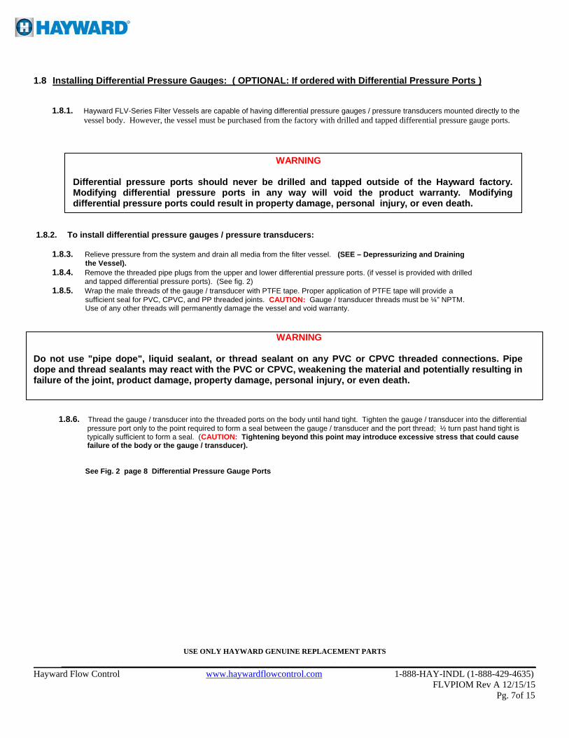
1.8 Installing Differential Pressure Gauges: ( OPTIONAL: If ordered with Differential Pressure Ports ) 1.8.1. Hayward FLV-Series Filter Vessels are capable of having differential pressure gauges / pressure transducers mounted directly to the vessel body. However, the vessel must be purchased from the factory with drilled and tapped differential pressure gauge ports.
WARNING
Differential pressure ports should never be drilled and tapped outside of the Hayward factory. Modifying differential pressure ports in any way will void the product warranty. Modifying differential pressure ports could result in property damage, personal injury, or even death.
1.8.2. To install differential pressure gauges / pressure transducers: 1.8.3. Relieve pressure from the system and drain all media from the filter vessel. (SEE – Depressurizing and Draining the Vessel). 1.8.4. Remove the threaded pipe plugs from the upper and lower differential pressure ports. (if vessel is provided with drilled and tapped differential pressure ports). (See fig. 2) 1.8.5. Wrap the male threads of the gauge / transducer with PTFE tape. Proper application of PTFE tape will provide a sufficient seal for PVC, CPVC, and PP threaded joints. CAUTION: Gauge / transducer threads must be ¼” NPTM. Use of any other threads will permanently damage the vessel and void warranty. WARNING Do not use "pipe dope", liquid sealant, or thread sealant on any PVC or CPVC threaded connections. Pipe dope and thread sealants may react with the PVC or CPVC, weakening the material and potentially resulting in failure of the joint, product damage, property damage, personal injury, or even death. 1.8.6. Thread the gauge / transducer into the threaded ports on the body until hand tight. Tighten the gauge / transducer into the differential pressure port only to the point required to form a seal between the gauge / transducer and the port thread; ½ turn past hand tight is typically sufficient to form a seal. (CAUTION: Tightening beyond this point may introduce excessive stress that could cause failure of the body or the gauge / transducer). See Fig. 2 page 8 Differential Pressure Gauge Ports
USE ONLY HAYWARD GENUINE REPLACEMENT PARTS _____________________________________________________________________________________ Hayward Flow Control www.haywardflowcontrol.com 1-888-HAY-INDL (1-888-429-4635) FLVPIOM Rev A 12/15/15 Pg. 7of 15

2.0 Operation:
2.1 Filling and Pressurizing the Vessel: 2.1.1. To fill and pressurize Hayward FLV-Series filter vessel: 2.1.2. Verify that the cover o-ring groove, and cover sealing surface are clean. 2.1.3. Verify that the cover o-ring is seated inside the o-ring groove. 2.1.4. Open the vent valve on top of the cover (valve is opened by rotating thumbwheel counter clockwise). NOTE: Process media will be allowed to escape through the outlet of the vent valve as the vessel is filled. If needed, install ¼ drain tubing on the outlet of the vent valve to prevent property damage or personal injury due to contact with process media. Dispose of vented chemicals properly. 2.1.5. Install the cover firmly onto the vessel body. CAUTION: lubrication of body threads and or cover threads is not necessary. 2.1.6. Do not strike the cover. 2.1.7. Do not attempt to over tighten the cover. 2.1.8. Cover is sealed by means of a pressure energized face sealing o-ring. Tighten the cover hand tight plus approximately 1/8 turn (i.e. 45°). It is not necessary to tighten the cover beyond hand tight plus 1/8 turn. 2.1.9. Slowly open valve upstream of the vessel and start system pump (if necessary). 2.1.10. Allow process media to fill the vessel. Air inside the vessel will be purged through the vent valve on top of the cover. After all air has been purged, process media will start flowing through the vent valve.
USE ONLY HAYWARD GENUINE REPLACEMENT PARTS _____________________________________________________________________________________ Hayward Flow Control www.haywardflowcontrol.com 1-888-HAY-INDL (1-888-429-4635) FLVPIOM Rev A 12/15/15 Pg. 8of 15

2.1.11. Close the vent valve by rotating the thumbwheel clockwise. 2.1.12. Carefully inspect the vessel at the cofer, end connectors, end caps, and vent valve to verify no leaks are present. If any leaks are present, shut down the system, relieve the system pressure (see section 2.4) and drain vessel prior to tightening any connections.
WARNING Open and close valves upstream and downstream of the FLV-Series filter vessel slowly. Rapid increases in pressure or flow can create excess water hammer effect, resulting in property damage, personal injury, or even
WARNING
If vessel is leaking, never try to stop the leak while vessel is under pressure. Doing so can result in property damage, personal injury, or even death.
WARNING
Failure to fill vessel with vent valve installed and open can result in buildup of pressure and compression of air in the system, resulting in property damage, personal injury, or even death. 2.2 Operating the Vessel:
2.2.1. Valves upstream and down steam of the vessel should be opened and closed slowly to prevent water hammer on the vessel
and system.
WARNING Open and close valves upstream and downstream of the FLV-Series filter vessel slowly. Rapid increases in pressure or flow can create excess water hammer effect, resulting in property damage, personal injury, or even death. 2.2.2. Hayward recommends the installation and use of monitoring gauges upstream and downstream of each vessel in order to monitor the increase in differential pressure that will occur as the bag becomes fouled. (See Section 1.8 ) 2.2.3. Replace the filter bags at 10 p.s.i. differential pressure. Filter bags lose efficiency above this level. 2.3 Depressurizing and Draining the Vessel:
CAUTION: Systems should always be depressurized and drained prior to installing or maintaining any Hayward product. WARNING
Failure to depressurize and drain system prior to installing or maintaining filter vessel may result in product damage, property damage, personal injury, or even death. WARNING Open and close valves upstream and downstream of the FLV-Series filter vessel slowly. Rapid increases in pressure or flow can create excess water hammer effect, resulting in property damage, personal injury, or even death.
USE ONLY HAYWARD GENUINE REPLACEMENT PARTS
_____________________________________________________________________________________ Hayward Flow Control www.haywardflowcontrol.com 1-888-HAY-INDL (1-888-429-4635) FLVPIOM Rev A 12/15/15 Pg. 9of 15

2.3.1. Slowly close valves upstream and downstream of filter vessel. 2.3.2. Slowly open vent valve on top of the cover (valve is opened by rotating the thumbwheel counter clockwise). NOTE: Process media will be allowed to escape through outlet of valve as the vessel depressurizes. If needed, install ¼” drain tubing on outlet of vent valve to prevent property damage or personal injury due to contact with the process media. Dispose of the vented line media properly. 2.3.3. After all the pressure has been relieved, remove the plug from the drain port and allow the vessel to drain completely. Capture and dispose of the drained chemicals properly. (See fig. 4.) 2.3.4. For faster draining, the nut of the lower end cap port can be loosened to allow drainage from this port. Alternatively, a Hayward TB Series ball valve can be installed to drain the vessel via this lower port. CAUTION: Do not lose the o-ring that seals the port cap to the vessel body. ( See picture next page ). 2.4 Removing Filter Bag:
WARNING
NEVER open the filter vessel while the vessel is pressurized. ALWAYS be aware of what type of media has been flowing through the vessel. ALWAYS use approved eye and skin protection when opening the vessel and during bag removal / change-out. ALWAYS open vent valve on the filter vessel cover to relieve any remaining internal pressures. If the vent valve has been connected to some type of external recovery system, carefully disconnect. NOTICE: Hayward recommends changing filter bags when differential pressure reaches 10 psi. The effectiveness of most filter bags declines as differential pressure increases beyond 10 psi. 2.4.1. With the vent valve still open, remove the drain plug from the lower end of the filter vessel body. Unless the drain has been connected to an external recovery system, be sure to use a container of adequate size to collect any remaining media that may drain out of the filter vessel. 2.4.2. Carefully rotate the cover counter clockwise until the cover is completely disengaged from the filter vessel body being sure not to damage the internal threads. 2.4.3. Remove the bag retainer to expose the top of the bag. 2.4.4. Grasp the bag handle, if provided. 2.4.5. Carefully lift/remove the bag from inside the basket. Take care to avoid possible damage and or tearing of the bag fabric during removal, as filtered debris could potentially find its way back into the filter vessel body and downstream.
USE ONLY HAYWARD GENUINE REPLACEMENT PARTS _____________________________________________________________________________________ Hayward Flow Control www.haywardflowcontrol.com 1-888-HAY-INDL (1-888-429-4635) FLVPIOM Rev A 12/15/15 Pg. 10 of 15

2.5 Vessel Maintenance:
2.5.1. Clean the internal cover threads and external body threads each time the cover is removed. Threads should be cleaned with a soft Brush or cloth. Care should be taken not to damage the threads. If the cover or nut threads are damaged due to normal wear and tear, replace the damaged cover or nuts. If the body threads are damaged, replace the entire unit. 2.5.2. Clean and inspect the o-ring grooves and o-rings each time the cover or end connector is removed. Damaged o-rings should be replaced Immediately.
WARNING
The filter vessel should never be pressurized with damaged threads on the cover, body, or assembly nuts. Use of a filter vessel with damaged threads could result in property damage, personal injury, or even death.
WARNING
If the nuts or cover ever fail due to over pressurization or water hammer failure, the entire unit needs to be replaced. Failure to replace the unit after water hammer failure, or failure due to over pressurization could result in property damage, personal injury, or even death.
USE ONLY HAYWARD GENUINE REPLACEMENT PARTS _____________________________________________________________________________________ Hayward Flow Control www.haywardflowcontrol.com 1-888-HAY-INDL (1-888-429-4635) FLVPIOM Rev A 12/15/15 Pg. 11of 15

2.6 Troubleshooting: Problem Cause Solution
Leak between cover and body
Damaged o-ring Remove cover and carefully inspect o-ring for cuts, impressions, or other damage. Replace o-ring if damaged.
Debris in o-ring groove
Remove cover and o-ring. Clean o-ring groove using care not to scratch sealing surface. O-ring groove is tapered to center of vessel, and has four drain slots to allow rinsing of groove during vessel maintenance.
Loose cover / Over-tightened cover
Tighten cover hand tight plus 1/8-turn (45º). Cover should not require tightening beyond this point. Never strike cover. Never use “cheater” bar to tighten or loosen cover.
Missing o-ring Remove cover, clean groove, and install new o-ring.
Leak between end connector and body
Damaged o-ring
Remove assembly nut and end connector. Carefully inspect o-ring for cuts, impressions, or other damage. Replace o- ring if damaged.
Loose assembly nut Tighten assembly nut hand tight. Using strap wrench, gently tighten assembly nut an additional ¼-turn (90º).
Missing o-ring Remove assembly nut and end connector. Clean o-ring groove and install new o-ring.
Increase in pressure drop Fouled bag Replace fouled bag with new bag. Never allow differential
pressure across vessel to exceed 10 p.s.i.d.
Reduction in flow through unit Fouled bag Replace fouled bag with new bag. Never allow differential
pressure across vessel to exceed 10 p.s.i.d.
Bypass of filtered media
Missing or damaged basket ring o-ring Inspect basket ring o-ring. Replace if damaged or missing.
Missing bag ring Install bag and retainer.
Improperly seated bag / bag ring Check alignment and fit of bag with counter bore of basket. See Section 2.5 for bag installation instructions.
Improper bag selection Review system requirements, use next lowest micron rated bag.
USE ONLY HAYWARD GENUINE REPLACEMENT PARTS _____________________________________________________________________________________ Hayward Flow Control www.haywardflowcontrol.com 1-888-HAY-INDL (1-888-429-4635) FLVPIOM Rev A 12/15/15 Pg. 12 of 15

2.7 PRODUCT SPECIFICATIONS:
Max. Pressure: 150 psi @ 70ºF (see Chart 1 for operating pressures at elevated temperatures)
Max. Temperature: CPVC: 190ºF (see Chart 1) PVC: 140ºF (see Chart 1)
Max. Flow Rate: 1-1/4” – 2”: 100 GPM, Size 1 (16”) and Size 2 (32”) vessels
2-1/2” – 4”: 150 GPM, Size 2 (32”) vessels 2 NOTE: Flow rate may be limited by bag selection.
WARNING The maximum recommended fluid velocity through any plastic piping system is eight feet per second (8 ft/s). Higher fluid velocity can create excess water hammer effect, resulting in property damage, personal injury, or even death. WARNING Published operating requirements are based on testing of new vessels using clean water at 70° F. Vessel performance is affected by many factors including chemistry, viscosity, specific gravity, flow rate, and temperatures. These should be considered when sizing Hayward products.
Chart 1: Operating pressures at elevated temperatures
USE ONLY HAYWARD GENUINE REPLACEMENT PARTS _____________________________________________________________________________________ Hayward Flow Control www.haywardflowcontrol.com 1-888-HAY-INDL (1-888-429-4635) FLVPIOM Rev A 12/15/15 Pg. 13 of 15
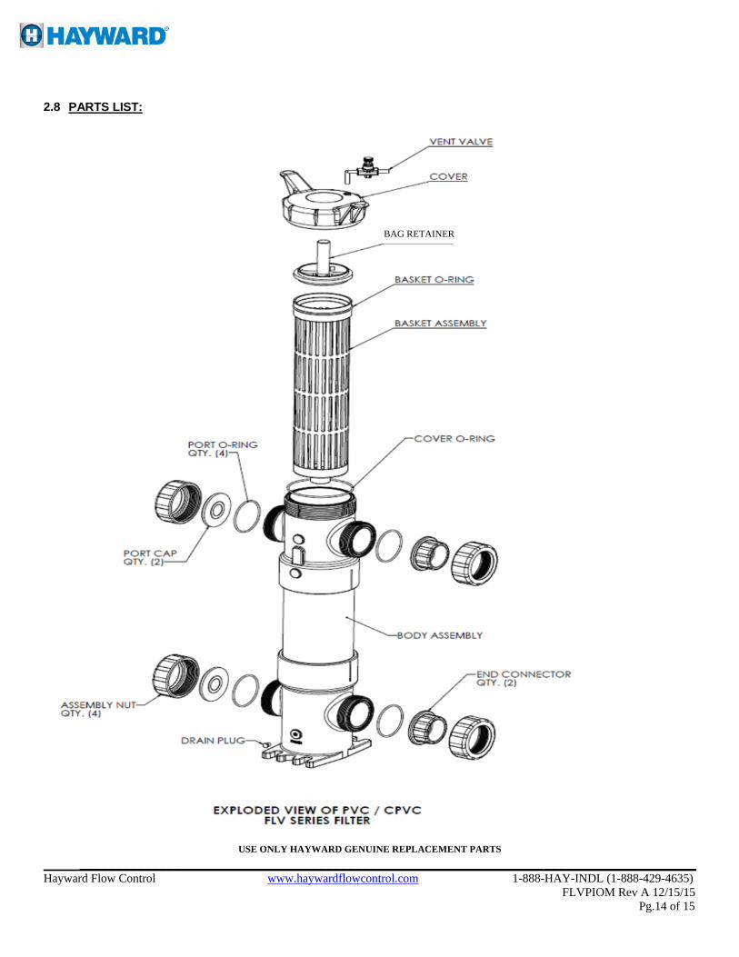
2.8 PARTS LIST:
USE ONLY HAYWARD GENUINE REPLACEMENT PARTS _____________________________________________________________________________________ Hayward Flow Control www.haywardflowcontrol.com 1-888-HAY-INDL (1-888-429-4635) FLVPIOM Rev A 12/15/15 Pg.14 of 15
BAG RETAINER
3.0 Warranty Terms and Conditions:
TWO YEAR WARRANTY: All products manufactured by Hayward are warranted against defects in material or workmanship for a period of two years from date of shipment. Our sole obligation under this warranty is to repair or replace, at our option, any product or any part or parts thereof found to be defective. HAYWARD MAKES NO OTHER REPRESENTATION OR WARRANTY, EXPRESS OR IMPLIED, INCLUDING, BUT NOT LIMITED TO, ANY IMPLIED WARRANTY OF MERCHANTABILITY OR FITNESS FOR A PARTICULAR PURPOSE. The warranty set forth above is the only warranty applicable to Hayward products and in no event shall Hayward be liable for any delay, work stoppage, cartage, shipping, loss of use of equipment, loss of time, inconvenience, loss of profits of any direct or indirect incidental resulting from or attributable to a breach of warranty. The remedies under this warranty shall be the only remedies available. OUR MAXIMUM LIABILITY SHALL NOT IN ANY EVENT EXCEED THE CONTRACT PRICE FOR THE PRODUCT.
USE ONLY HAYWARD GENUINE REPLACEMENT PARTS _____________________________________________________________________________________ Hayward Flow Control www.haywardflowcontrol.com 1-888-HAY-INDL (1-888-429-4635) FLVPIOM Rev A 12/15/15 Pg. 15 of 15

![Improved multiscale matched filter for retina vessel segmentation … · 2017. 1. 19. · Retinal Images for Vessel Extraction (DRIVE) database [9], introduced in 2004. Database contains](https://static.fdocuments.in/doc/165x107/60517afc8a35ef5cec2242d8/improved-multiscale-matched-filter-for-retina-vessel-segmentation-2017-1-19.jpg)